Gas Balanced Flue Guide - Euroheat
Gas Balanced Flue Guide - Euroheat
Gas Balanced Flue Guide - Euroheat

You also want an ePaper? Increase the reach of your titles
YUMPU automatically turns print PDFs into web optimized ePapers that Google loves.
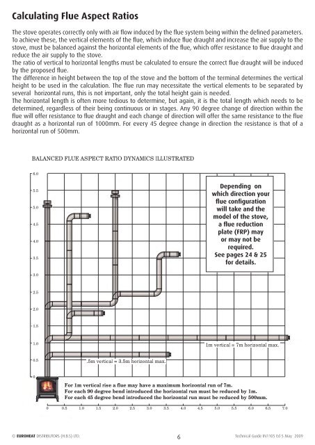
Calculating <strong>Flue</strong> Aspect Ratios<br />
The stove operates correctly only with air flow induced by the flue system being within the defined parameters.<br />
To achieve these, the vertical elements of the flue, which induce flue draught and increase the air supply to the<br />
stove, must be balanced against the horizontal elements of the flue, which offer resistance to flue draught and<br />
reduce the air supply to the stove.<br />
The ratio of vertical to horizontal lengths must be calculated to ensure the correct flue draught will be induced<br />
by the proposed flue.<br />
The difference in height between the top of the stove and the bottom of the terminal determines the vertical<br />
height to be used in the calculation. The flue run may necessitate the vertical elements to be separated by<br />
several horizontal runs, this is not important, only the total height gain is needed.<br />
The horizontal length is often more tedious to determine, but again, it is the total length which needs to be<br />
determined, regardless of their being continuous or in stages. Any 90 degree change of direction within the<br />
flue will offer resistance to flue draught and each change of direction will offer the same resistance to the flue<br />
draught as a horizontal run of 1000mm. For every 45 degree change in direction the resistance is that of a<br />
horizontal run of 500mm.<br />
BALANCED FLUE ASPECT RATIO DYNAMICS ILLUSTRATED<br />
6.0<br />
5.5<br />
5.0<br />
4.5<br />
4.0<br />
3.5<br />
3.0<br />
2.5<br />
2.0<br />
1.5<br />
1.0<br />
0.5<br />
0<br />
.5m vertical = 3.5m horizontal max.<br />
Depending on<br />
which direction your<br />
flue configuration<br />
will take and the<br />
model of the stove,<br />
a flue reduction<br />
plate (FRP) may<br />
or may not be<br />
required.<br />
See pages 24 & 25<br />
for details.<br />
1m vertical = 7m horizontal max.<br />
For 1m vertical rise a flue may have a maximum horizontal run of 7m.<br />
For each 90 degree bend introduced the horizontal run must be reduced by 1m.<br />
For each 45 degree bend introduced the horizontal run must be reduced by 500mm.<br />
0 0.5 1.0 1.5 2.0 2.5 3.0 3.5 4.0 4.5 5.0 5.5 6.0 6.5 7.0<br />
© EUROHEAT DISTRIBUTORS (H.B.S) LTD. 6<br />
Technical <strong>Guide</strong> IN1105 Ed 5 May 2009