Memo Operating Instruct - Euroheat
Memo Operating Instruct - Euroheat
Memo Operating Instruct - Euroheat

You also want an ePaper? Increase the reach of your titles
YUMPU automatically turns print PDFs into web optimized ePapers that Google loves.
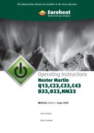
This Manual Must Always be Available to the Stove Operator<br />
<strong>Operating</strong> <strong>Instruct</strong>ions<br />
<strong>Memo</strong><br />
Wood Pellet Burning Stoves<br />
IN1228 Edition 1 June 2011<br />
PART NUMBER<br />
SERIAL NUMBER
Contents<br />
The Model Range Explained ............................................................................................4<br />
Model Identification ........................................................................................................4<br />
Technical Data .................................................................................................................5<br />
The Clean Air Act 1993 ....................................................................................................5<br />
Spare Parts Overview ......................................................................................................6<br />
Dimensions .....................................................................................................................8<br />
General Warning and Safety Information .......................................................................9<br />
Wood Pellet Specification According to ENplus – A1 ......................................................10<br />
<strong>Operating</strong> Comfort – Operational Reliability .................................................................11<br />
Highest Efficiency – Lowest Emissions ...........................................................................11<br />
Automatic Safety Function ............................................................................................11<br />
Electrical Connection .....................................................................................................12<br />
Combustion Air .............................................................................................................12<br />
Disassembly of Panels ..................................................................................................13<br />
Operation ......................................................................................................................14<br />
Control and Internal Control Unit - Function ..................................................................14<br />
Over View of Heating Modes .........................................................................................15<br />
Simple Heating Operation – Easy Mode – The First Steps ...............................................15<br />
Easy Off – Inactive State ................................................................................................16<br />
Easy 40 – Operation .......................................................................................................16<br />
Easy 40 – switch Off ......................................................................................................16<br />
Extended Heating Operation – Heat Mode – Comfort Functions ....................................17<br />
Menu Structure and Main Menu Level ...........................................................................18<br />
Main Menu Time – Time Adjustment .............................................................................19<br />
Main Menu Setup – Additional Functions ......................................................................20<br />
Main Menu Info – Additional Functions .........................................................................22<br />
Rika Wireless Room Sensor and Telephone Option-GSM ...............................................24<br />
Electric Ignition .............................................................................................................25<br />
Emergency Operation – Heating Up without Electrical Ignition .....................................25<br />
Cleaning and Maintenance ...........................................................................................26<br />
Malfunctions – Causes – Solutions .................................................................................30<br />
Menu Navigation – Overall View ...................................................................................32<br />
Rika Warranty ...............................................................................................................35<br />
© EUROHEAT DISTRIBUTORS (H.B.S) LTD. June 2011 2<br />
<strong>Instruct</strong>ions Part Number IN1228 Ed 1
IMPORTANT<br />
The installation of this appliance must comply with all local regulations, including those referring to<br />
National and European Standards before it can be operated. The stove is not suitable for a shared flue.<br />
Improper adjustment, alteration, maintenance or the fitting of replacement parts not recommended<br />
by the manufacturer can cause injury or property damage. Do not operate the stove with faulty seals<br />
or damaged glass.<br />
Ensure all manuals are kept safely and are available for the user at all times.<br />
Do not store or use petrol or other flammable vapours and liquids in the vicinity of this or any other<br />
heating appliance. Do not use aerosol sprays near the stove when the stove is alight. Do not burn<br />
anything but approved wood pellets on this appliance.<br />
Due to the high operating temperatures of this appliance it should be located away from pedestrian<br />
traffic and away from furniture and draperies. Do not store paper or wood near the appliance. Any mats<br />
or rugs put in front of the stove should be fire proof and secured to prevent the possibility of tripping.<br />
Advise all persons as to the stove’s high surface temperatures, including visitors. If it is possible for<br />
children or infirm adults to come into contact with the stove, fit a suitable fire guard. Never let<br />
children “help” with the stove in any way, even when the stove is cold.<br />
It is imperative that all air passageways into, out of, and within the appliance are kept clean. All<br />
permanent ventilation into the room provided for the stove must remain clear and unobstructed at all<br />
times. Consideration must be given to the need for extra ventilation if another heating source needing<br />
air is to be operated simultaneously. If an extraction fan is proposed to be fitted to a connecting<br />
area of the house, after the stove has been installed, professional advice should be sought from a<br />
qualified engineer.<br />
If a flue blockage or adverse weather conditions cause the appliance to emit smoke, do not treat it as<br />
merely a nuisance, this smoke will indicate that carbon monoxide is being emitted into the room.<br />
Properly installed, operated and maintained this applinace will not emit fumes into the dwelling.<br />
WARNING: If fume emissions persist the following immediate action should be taken:<br />
Turn the stove off, on the control panel, open windows to ventilate the room and leave the premises<br />
and allow the appliance to go out before closing the windows. Do not re-light the stove without<br />
consulting a qualified engineer.<br />
Your installing engineer should have fitted a CO alarm in the same room as the stove. If the alarm<br />
sounds unexpectedly, follow the instructions in the above paragraph.<br />
In the event of a chimney fire the stove should be turned to off and the fire brigade informed.<br />
Do not re-light the stove until the complete installation has been inspected by a qualified<br />
engineer.<br />
The appliance should be inspected and cleaned regularly and the chimney cleaned at least annually.<br />
More frequent cleaning may be required and the advice of a qualified chimney sweep should be<br />
sought. Always check for any flue blockage before lighting the appliance after a prolonged shut down.<br />
This appliance has been carefully designed and constructed to give clean burning with optimum efficiency<br />
and safety, but as with all heating appliances these standards will not be achieved unless it is installed and<br />
maintained regularly by qualified engineers. It must also be operated strictly with the procedures given in this<br />
manual.<br />
If you are unsure about anything concerning your stove please seek professional advice.<br />
© EUROHEAT DISTRIBUTORS (H.B.S) LTD. June 2011 3<br />
<strong>Instruct</strong>ions Part Number IN1228 Ed 1
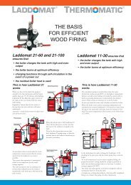
The Model Range Explained<br />
Thank you for purchasing your stove and helping to protect our environment. RIKA and <strong>Euroheat</strong> insist on<br />
progressive development to produce products which are market leading. Our aims are to produce stoves with<br />
the latest innovations, user friendly operation and high efficiency for lower cost operation.<br />
This operating manual offers user information for the Como pellet stoves.<br />
Model Identification<br />
You will see on the front page of this document a label which confirms which model you have. This label also<br />
advises you of the stoves unique serial number. This information is also attached to your stove for reference.<br />
Important<br />
Please ensure the warranty registration form is returned to <strong>Euroheat</strong>. In this way the model and its history will<br />
be recorded for reference in the future.<br />
Stoves supplied through <strong>Euroheat</strong> authorized retailers.<br />
For England, Wales, Scotland and Northern Ireland<br />
<strong>Euroheat</strong> Distributors (H.B.S). Ltd.<br />
Unit 2,<br />
Court Farm Business Park,<br />
Bishops Frome,<br />
Worcestershire. WR6 5AY.<br />
www.euroheat.co.uk<br />
info@euroheat.co.uk<br />
Whilst we are always happy to assist you, please make sure you have read this manual before requesting<br />
support. First contact your supplying retailer. If you find this not successful contact the <strong>Euroheat</strong> Technical<br />
Support Team.<br />
Technical support telephone number 01885 491117. E-mail tech@euroheat.co.uk. Before telephoning ensure<br />
you have your stove’s serial number to hand. This can be found on the front of either the operating, installation,<br />
warranty registration, or on the stove identification label.<br />
<strong>Euroheat</strong> unfortunately are unable to offer support for appliances which were not supplied by <strong>Euroheat</strong>.<br />
RIKA Innovative Ofentechnik GmbH<br />
Müllerviertel 20<br />
AT - 4563 Micheldorf<br />
Tel.: 0043 (0)7582 / 686 - 41<br />
Fax: 0043 (0)7582 / 686 - 43<br />
Email: office@rika.at<br />
Website: www.rika.at<br />
© EUROHEAT DISTRIBUTORS (H.B.S) LTD. June 2011 4<br />
<strong>Instruct</strong>ions Part Number IN1228 Ed 1
THE CLEAN AIR ACT 1993 AND<br />
SMOKE CONTROL AREAS<br />
Technical Specification - Como<br />
Dimensions (mm) and weights (kg)<br />
Height 978<br />
Width 495<br />
Depth of the body 544<br />
Weight with steel casing 95<br />
Weight with ceramic casing 110<br />
Flue tube outlet diameter 100<br />
Heating capacity range 2.4-9 kW<br />
Room heating capacity (m3)<br />
depended on the house insulation<br />
50-240<br />
Fuel consumption Up to 2.2 kg/h<br />
Pellet container capacity 17 kg<br />
Mains supply 230V/50Hz<br />
Average electric power<br />
consuption<br />
< 100 W<br />
Protection (fuse) A 1.6 T<br />
Efficiency (net)/(gross) % 92.1/84.6<br />
CO2 content 11.1 %<br />
CO emission (at 13% O) 34 mg/Nm3<br />
Dust emissions 22 mg/Nm3<br />
Exhaust gas mass flow 6.45 g/s<br />
Exhaust gas temperature 144 °C<br />
Flue draught requirement 0 PA<br />
Under the Clean Air Act 1993 local authorities may declare the whole or part of the district of the authority to<br />
be a smoke control area. It is an offence to emit smoke from a chimney of a building, from a furnace or from<br />
any fixed boiler if located in a designated smoke control area. It is also an offence to acquire an “unauthorised<br />
fuel” for use within a smoke control area unless it is used in an “exempt” appliance (“exempted” from the<br />
controls which generally apply in the smoke control area).<br />
The Secretary of State for Environment, Food and Rural Affairs has powers under the Act to authorise smokeless<br />
fuels or exempt appliances for use in smoke control areas in England. In Scotland and Wales this power rests<br />
with Ministers in the devolved administrations for those countries. Separate legislation, the Clean Air (Northern<br />
Ireland) Order 1981, applies in Northern Ireland. Therefore it is a requirement that fuels burnt or obtained<br />
for use in smoke control areas have been “authorised” in Regulations and that appliances used to burn solid<br />
fuel in those areas (other than “authorised” fuels) have been exempted by an Order made and signed by the<br />
Secretary of State or Minister in the devolved administrations.<br />
Further information on the requirements of the Clean Air Act can be found here: http://smokecontrol.defra.<br />
gov.uk/<br />
Your local authority is responsible for implementing the Clean Air Act 1993 including designation and supervision<br />
of smoke control areas and you can contact them for details of Clean Air Act requirements.<br />
The <strong>Memo</strong> pellet fuelled appliance has been assessed and is suitable for use in smoke control areas when<br />
burning 6mm wood pellets and when operated in accordance with these operating instructions.<br />
5<br />
© EUROHEAT DISTRIBUTORS (H.B.S) LTD. June 2011 <strong>Instruct</strong>ions Part Number IN1228 Ed 1
Spare Parts Overview<br />
18<br />
61<br />
60<br />
62<br />
59<br />
1<br />
13<br />
2<br />
50 51 52<br />
4<br />
3<br />
11<br />
5<br />
6<br />
8<br />
7<br />
9<br />
10<br />
16<br />
17 20<br />
53 54 55 57<br />
63 58<br />
© EUROHEAT DISTRIBUTORS (H.B.S) LTD. June 2011 6<br />
<strong>Instruct</strong>ions Part Number IN1228 Ed 1<br />
19<br />
27<br />
14<br />
28<br />
15<br />
6<br />
35<br />
35<br />
24<br />
25<br />
29<br />
34<br />
33<br />
36<br />
26<br />
32<br />
21<br />
9<br />
31<br />
58<br />
22<br />
30<br />
23
Spare parts overview; continued<br />
Pic No: Description Part No:<br />
1 Protection plate complete RK 111515<br />
2 Sensor clamp RK Z31459<br />
3 Control panel RK B15621<br />
4 Tension plate RK L00426<br />
5 Hopper complete RK B15782<br />
6 Combustion chamber sensor RK 111515<br />
7 Fuse holder RK 107887<br />
8 Safety temperature limiter RK 111586<br />
9 Ignition cartridge RK Z32147<br />
10 Auger RK B12301<br />
11 Geared motor 220V/50Hz RK 111634<br />
13 Fan complete RK B15587<br />
14 Combustion chamber door RK B15249<br />
15 Door glass RK Z32340<br />
16 Locking bolt RK Z32719<br />
17 Glass retainer RK L00437<br />
18 Combustion chamber cover RK B15244<br />
19 Rope seal D12 RK 100485<br />
20 Flat sealing strip 8x2 RK 102693<br />
21 Door handle tool RK Z30493<br />
22 Sintered bearing D16 RK 108310<br />
23 Sintered bearing ESSEM RK 102688<br />
24 Motherboard RK B16270<br />
25 Door contact switch RK 111499<br />
26 Capacitor RK 111597<br />
27 Fan housing RK B16155<br />
28 Fan motor RK 111581<br />
29 O-ring D76/4.5 RK 108315<br />
30 Cleaning opening, grey RK Z32422<br />
31 Hexagon socket screw RK 100055<br />
32 Combustion chamber front RK B15243<br />
33 Hinge RK B14478<br />
Pic No: Description Part No:<br />
34 Cage nut M8 RK 106591<br />
35 Crucible holder RK Z32345<br />
36 Pipe adapter RK Z18502<br />
37 Cable harness RK B15800<br />
50 Cover left cpl. RK L01018<br />
51 Convection fin cpl. RK B16020<br />
52 Hopper cover RK L01021<br />
53<br />
Rear panel top<br />
Rear panel bottom<br />
RK L01016<br />
RK L01025<br />
54 Cover right cpl. RK L01017<br />
55 Casing right, cast grey RK LB00441<br />
© EUROHEAT DISTRIBUTORS (H.B.S) LTD. June 2011 7<br />
<strong>Instruct</strong>ions Part Number IN1228 Ed 1<br />
57<br />
Casing right ceramic<br />
version*<br />
Depends on<br />
colour<br />
58 Supply air flange RK Z18278<br />
59 Casing front/bottom, silver RK Z32424<br />
60<br />
61<br />
Casing front/bottom,<br />
ceramic version*<br />
Casing front/top, ceramic<br />
version*<br />
Depends on<br />
colour<br />
Depends on<br />
colour<br />
62 Casing front/top silver RK B15790<br />
65 Casing left cpl., cast grey RK LB00442<br />
66<br />
Casing left cpl., ceramic<br />
version*<br />
Depends on<br />
colour
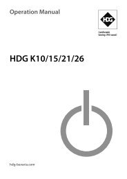
Dimensions<br />
495<br />
544<br />
119<br />
Fresh air inlet<br />
202 202<br />
© EUROHEAT DISTRIBUTORS (H.B.S) LTD. June 2011 8<br />
<strong>Instruct</strong>ions Part Number IN1228 Ed 1<br />
Flue outlet<br />
152<br />
978
General Warning and Safety Information<br />
Observance of the introductory general warning information is imperative.<br />
Read the entire manual thoroughly prior to putting the stove into operation.<br />
Only approved transport equipment with sufficient load carrying capacity may be used with your heating<br />
appliance.<br />
The burning of fuel releases heat energy that leads to extensive heating of the stove surfaces, doors, door<br />
and operating handles, glass, flue pipes and possibly the front wall. Refrain from touching these parts without<br />
appropriate protective clothing or equipment e.g. heat-resistant gloves or means of operation (operating<br />
handle).<br />
Make your children aware of this particular danger and keep them away from the stove during heating, fit a<br />
suitable fire guard where required.<br />
Placing non-heat resistant objects on the stove or near it is prohibited.<br />
Do not place clothing on the stove to dry.<br />
Stands for drying clothes etc. must be placed at a sufficient distance to the stove – FIRE HAZARD.<br />
When your stove is burning, the use of highly inflammable and explosive materials in the same or adjacent<br />
rooms is prohibited.<br />
ATTENTION<br />
Do not open the combustion chamber door during operation.<br />
CAUTION when filling the supply container.<br />
We recommend the pellet container is refilled only when the stove is cold.<br />
The pellet container opening is sufficient to ensure easy filling. Take great care that no pellets drop onto the<br />
convection fins and the stove body, if they do remove. This may lead to severe smoke development and the<br />
possibility of them igniting.<br />
© EUROHEAT DISTRIBUTORS (H.B.S) LTD. June 2011 9<br />
<strong>Instruct</strong>ions Part Number IN1228 Ed 1
What are Pellets ?<br />
Wood pellets are a standardised fuel. Every manufacturer must adhere to<br />
certain conditions in order to enable flawless, energy-efficient heating. Pellets<br />
are made from wood waste, from sawmills and planning workshops, as well as<br />
from residue from forestry operations. These “starting products” are crushed,<br />
dried, and pressed into Pellet “Fuel” without any bonding agent.<br />
ENplus – Pellets<br />
This new standard for pellets sets a new benchmark in the European pellet<br />
market. The traceability of pellets is ensured thanks to the use of identification<br />
numbers. The pellet manufacturers’ production facilities and manufacturing<br />
processes are reviewed every year. A quality assurance system ensures the<br />
pellets comply with the requirements of the new standard and that the conditions for trouble-free heating are<br />
guaranteed.<br />
Wood Pellet Specification according to ENplus – A1<br />
Parameter Unit ENplus-A1<br />
Diameter mm 6 (±1) (2)<br />
Length mm 3.15 to 40 (3)<br />
Bulk density kg/m³ ≥ 600<br />
Calorific value MJ/kg ≥ 16.5<br />
Water content Ma.-% ≤ 10<br />
Fine fraction (< 3.15 mm) Ma.-% ≤ 1<br />
Mechanical rigidity Ma.-% ≥ 97.5 (4)<br />
Ash content Ma.-% (1) ≤ 0.7<br />
Ash softening temperature (DT) °C ≥ 1200<br />
Chlorine content Ma.-% (1) ≤ 0.02<br />
Sulphur content Ma.-% (1) ≤ 0.03<br />
Nitrogen content Ma.-% (1) ≤ 0.3<br />
Copper content mg/kg (1) ≤ 10<br />
Chrome content mg/kg (1) ≤ 10<br />
Arsenic content mg/kg (1) ≤ 1<br />
Cadmium content mg/kg (1) ≤ 0.5<br />
Mercury content mg/kg (1) ≤ 0.1<br />
Lead content mg/kg (1) ≤ 10<br />
Nickel content mg/kg (1) ≤ 10<br />
Zinc content mg/kg (1) ≤ 100<br />
(1) in an anhydrous state<br />
(2) Diameter must be specified<br />
(3) a maximum of 1% of the pellets may be longer than 40 mm; max. length is 45 mm<br />
(4) The limit value of ≥ 97.7 Ma.-% applies when conducting measurements with a Lignotester (internal control)<br />
Pellet Storage<br />
In order to guarantee problem free burning of the wood pellets, it is imperative to store the fuel as dry as<br />
possible and free from impurities. Pellets should not be kept in sacks outdoors or stored in a manner where<br />
they are exposed to the environment. This can lead to blockages in the screw conveyor - “screw stoppers” are<br />
excluded from the warranty.<br />
Note: Waste and liquids may not be burnt in the stove.<br />
© EUROHEAT DISTRIBUTORS (H.B.S) LTD. June 2011 10<br />
<strong>Instruct</strong>ions Part Number IN1228 Ed 1
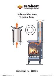
Technology<br />
Your new pellet stove is technologically advanced as a result of years of tests in the laboratory and in practice.<br />
The practical advantages of your pellet stove are convincing:<br />
<strong>Operating</strong> Comfort – Operational Reliability<br />
The electronic monitoring device together with a combustion temperature monitoring device controls and<br />
regulates the interplay of the flue gas fan, conveyor auger and temperature. This monitoring system guarantees<br />
an optimum combustion and operating mode. Your operating outlay is reduced to the most necessary - this<br />
prevents operating faults whilst working in an optimum fashion at the same time.<br />
The flame and drive motor noises permissible for the living space are therefore audible during operation.<br />
Highest Efficiency – Lowest Emissions<br />
A very large heat exchanger surface together with optimum combustion air control leads to very good fuel<br />
usage.<br />
Finely metered pellet feed in an optimised burner pot made from high quality grey cast iron effects almost<br />
perfect combustion with very good exhaust gas values - and this is guaranteed in every operating phase.<br />
Automatic Safety Function<br />
Power Failure (during heating operation)<br />
After a power failure the operating functions that were set before the power failure are continued.<br />
After a brief power failure, the operating functions set prior to the failure are continued. If the power failure<br />
lasts longer, the stove goes to start phase (display START) as long as sufficient temperature or embers are<br />
present. If the power failure lasts too long, the stove goes to STOP phase (display STOP – lasts approx. 10<br />
minutes). Re-start is then performed automatically (display IGNIT).<br />
Power Failure (during the start phase)<br />
The start procedure is continued after a brief power failure. If the power failure lasts longer and there are<br />
no embers available, then the stove goes to STOP phase. In the STOP phase (display STOP – lasts approx. 10<br />
minutes) only the blower runs to burn off any pellet residues. Re-start is then performed automatically (display<br />
IGNIT).<br />
Overheating<br />
A temperature safety switch (STB) switches the stove off automatically if it overheats. After the stove has<br />
cooled down the STB must be reset manually. The pellet stove can now be operated manually (or by means of<br />
a timer program) and it then goes into the regulating program again.<br />
CAUTION: If overheating has occurred then maintenance or cleaning work must be carried out.<br />
Low Temperature Switch Off<br />
If the stove cools down below a minimum temperature, then the stove will switch off. This switch off can also<br />
occur if pre-heating is too late.<br />
Electric Excess-Current Shut Off<br />
The device is protected against excess current by a main fuse (on the rear of the device), (data as per “Technical<br />
Specification”).<br />
© EUROHEAT DISTRIBUTORS (H.B.S) LTD. June 2011 11<br />
<strong>Instruct</strong>ions Part Number IN1228 Ed 1
Electrical Connection<br />
The stove is supplied with an approx. 2.5 m long connecting cable with a plug. This cable is to be connected<br />
to a 230 Volt, 50 Hz electrical connection. The average electric power consumption is approx 100 watts during<br />
heating.<br />
During the automatic ignition process (duration 10 minutes) approx. 350 watts. The connection cable must be<br />
laid so that any contact with hot or sharp edged external surfaces on the stove is avoided.<br />
Combustion Air<br />
Each combustion procedure requires oxygen or air. As a rule this combustion air is removed from the living<br />
area for individual stoves. The air taken from the living area must be reintroduced. In modern houses, very<br />
tight fitting windows and doors mean that too little air flows back. This situation becomes problematic due<br />
to additional ventilation in the house (e.g. in the kitchen or WC). Your qualified installing engineer will fit<br />
a suitable air brick/vent to ensure that the stove is supplied with enough free air as required by Building<br />
Regulations. A fresh air kit can be fitted directly to the stove, which will reduce the chance of draughts but still<br />
supply the free air for combustion.<br />
Feed of External Combustion Air (Fresh Air Kit)<br />
Steel, high temperature or aluminium pipes can be used.<br />
Minimum diameter 10 cm/4 inches.<br />
The pipe should not be longer than approx. 4 m to guarantee adequate air feed and not have too many<br />
bends.<br />
Should the line lead into the open air, it must end with a windguard (supplied with the fresh air kit).<br />
Make sure the supply air opening does not “ice over” during extremely cold periods (inspection).<br />
Further it is possible to extract the combustion air directly from outside or from another room that is well<br />
ventilated (e.g. the cellar).<br />
Should one or more of these conditions not be applicable then usually poor combustion will occur in the stove,<br />
as well as a vacuum in the room.<br />
Fresh air vent kit through wall showing minimum access for cleaning “x”<br />
© EUROHEAT DISTRIBUTORS (H.B.S) LTD. June 2011 12<br />
<strong>Instruct</strong>ions Part Number IN1228 Ed 1<br />
x
Disassembly of Panels<br />
CAUTION:<br />
Only work on the stove when the mains plug has been removed from the socket.<br />
During assembly do not drop any items (screws) etc. into the fuel container - they can block the conveyor<br />
auger and damage the stove.<br />
Your stove must be switched off and have cooled down before carrying out any work on it.<br />
Disassembly of Front Side Casing Panels<br />
1. Remove the hex head screw on the rear as well as the ISK<br />
screw behind the convection fins for the cover right<br />
(Part No. 54).<br />
Also remove these two screws on the left for the cover right<br />
(Part No. 50).<br />
Now remove the two covers from the unit.<br />
2. Remove the 4 hex head screws for the attachment of the<br />
convection fins (Part No. 51).<br />
Now lift off the convection fins.<br />
3. Remove the hex head screws on both sides of the panels<br />
front top (Part No. 61 or 62, depending on model) and remove<br />
the panels.<br />
4. Open the combustion chamber door and lift the panel front bottom (Part No. 59 or 60, depending on model)<br />
out of the holder brackets.<br />
Disassembly of Side Casing<br />
1. To disassemble the side panels right (Part No. 55 or 57, depending on model), remove the two hex head<br />
screws at the top as well as the two hex head screws connecting the side panels to the bottom (one hex head<br />
screw is screwed in the back; the second hex head screw is at the front right).<br />
Now lift off the side panels.<br />
2. Disassembly of the side panels left (Part No. 65 or 66, depending on model) is performed in the same way<br />
as for the side panels right.<br />
Exercise extreme caution during disassembly and/or assembly to ensure you do not scratch or damage the<br />
casing panels.<br />
© EUROHEAT DISTRIBUTORS (H.B.S) LTD. June 2011 13<br />
<strong>Instruct</strong>ions Part Number IN1228 Ed 1<br />
61<br />
60<br />
62<br />
59<br />
50 51 52<br />
53 54 55 57<br />
63 58
Operation<br />
Basic Information<br />
The stove must only be started when fully fitted.<br />
Your pellet stove is exclusively for burning pellets made from wood of a controlled quality. Non-pelletised<br />
solid fuels (straw, maize, chopped matter etc.) are not permitted. Failure to adhere to these guidelines will<br />
make all guarantee and warranty claims null and void and could have a negative effect on the safety of<br />
your stove.<br />
When operated correctly your pellet stove cannot overheat. Improper operation can however shorten the<br />
life expectancy of the electric stove components (fan, motors and electric control) and is not permitted.<br />
Control and Internal Control Unit - Function<br />
Your pellet stove is fitted with a modern programmable microprocessor control. The user can preset the individual<br />
stove functions via the internal control unit (keypad with operating display) fitted at the top of the right hand<br />
stove panel. The control (main board) and the control board may only be altered by trained specialist dealers<br />
or the service department. Improper handling of these parts leads to the guarantee and warranty becoming<br />
null and void.<br />
Internal Control Unit<br />
All settings and functions can be regulated via this unit.<br />
Menu<br />
+ -<br />
The display is illuminated when touched. After some seconds the display lighting turns off again.<br />
© EUROHEAT DISTRIBUTORS (H.B.S) LTD. June 2011 14<br />
<strong>Instruct</strong>ions Part Number IN1228 Ed 1
Over View of Heating Modes<br />
Easy Mode<br />
In the easy mode, the stove is simply switched on and off using the (power) key. The output of the stove can<br />
be altered in 5% increments from 30-100%.<br />
Comfort Modes (require connection of Rika room sensor or Rika wireless room sensor).<br />
Heat Mode<br />
This mode corresponds to the Easy Mode from basic operation, in which the heat output of the stove can be<br />
increased or decreased in 5% increments.<br />
Room<br />
In “Room” mode the heat output of the stove cannot be changed and is regulated by the electonic control. You<br />
do not need to worry about whether the stove heats up or not, the Rika room thermostat takes care of this<br />
depending on the prevailing temperature in the room.<br />
Auto Mode<br />
In “Auto” mode you have the additional possibility of calling up the set comfort temperature for two preset<br />
heating times each day or weeks automatically. In the time periods between the heating times a low<br />
temperature that you set is maintained.<br />
The heat output of the stove is regulated by the Rika room sensor.<br />
Simple Heating Operation – Easy Mode – The First Steps<br />
Software Version - 1.32<br />
Your stove is in simple heating mode EASY OFF when delivered in order to ease your start in the world of RIKA<br />
pellet stoves. The heat output of the stove can be increased or reduced in 5 % increments in this mode. As soon<br />
as the stove is connected to the socket, the standard display EASY OFF appears. The message “CHECK” appears<br />
in the display as soon as your pellet stove is connected to the power supply (even after a power failure). The<br />
display buttons are disabled for approx. 10 seconds as the stove conducts an initialisation of all components.<br />
When “CHECK” disappears from the display the stove can be started up. This procedure only occurs in the<br />
“EASY” and “HEAT” mode.<br />
“CHECK” appears in the display<br />
whenever the stove is re-supplied<br />
with power.<br />
E A S Y<br />
O F F<br />
C H E C K<br />
H E A T<br />
O F F<br />
© EUROHEAT DISTRIBUTORS (H.B.S) LTD. June 2011 15<br />
<strong>Instruct</strong>ions Part Number IN1228 Ed 1
Easy Off – Inactive State<br />
Key Display Description<br />
+<br />
EASY<br />
OFF<br />
EASY<br />
45<br />
EASY<br />
35<br />
Standard display for stove<br />
switched off in simple<br />
heating mode.<br />
The output can also be<br />
regulated between 30%<br />
and 100% with the stove<br />
switched off (EASY 30 –<br />
EASY 100).<br />
Pressing + increases<br />
output by 5%<br />
Pressing decreases<br />
output by 5%<br />
Start – Ignition Process<br />
The ignition process may take approx. 5 – 8 minutes<br />
until the first flame is visible (depending on how clean<br />
the fire crucible is).<br />
If the 1st ignition attempt is unsuccessful, a 2nd<br />
attempt is started automatically. This may occur if<br />
the screw conveyor is not completely full during the<br />
ignition process (e.g. first start after refilling empty<br />
container).<br />
Please observe:<br />
In the event of false start, completely empty fire<br />
trough and dispose of unburned pellets and ash.<br />
Never replace unburned pellets from the fire pot in<br />
the supply container.<br />
FIRE HAZARD DUE TO RESIDUAL EMBERS.<br />
Key Display Description<br />
Pressing starts the<br />
unit.<br />
This is shown by IGNITE in<br />
IGNITE the display; this is replaced<br />
by START after a brief time.<br />
START EASY xx appears in the<br />
display after the start<br />
EASY 35 phase<br />
(xx stands for a value<br />
between 30% and 100%,<br />
depending on output)<br />
If switching off occurs again 50 sec. within switching<br />
on ( key) (at least 2 sec. key), the pellet<br />
stove returns to inactive status.<br />
If switching off occurs during the ignition process<br />
(IGNIT or START) (at least 2 sec. key), IGNIT OFF<br />
or START OFF appears in the display and the burn-out<br />
phase is initiated (duration approx. 10 min).<br />
Easy 40 – Operation<br />
Key Display Description<br />
© EUROHEAT DISTRIBUTORS (H.B.S) LTD. June 2011 16<br />
<strong>Instruct</strong>ions Part Number IN1228 Ed 1<br />
+<br />
EASY<br />
40<br />
EASY<br />
45<br />
EASY<br />
40<br />
Easy 40 – Switch Off<br />
Standard display for stove<br />
switched on in simple<br />
heating mode. (40 is the<br />
output in %)<br />
Pressing + increases<br />
output by 5%<br />
Pressing decreases<br />
output by 5%<br />
Key Display Description<br />
STOP Pressing initiates the<br />
burn-out phase.<br />
EASY The unit switches off after<br />
OFF completion of the burn out<br />
phase.<br />
I G N I T<br />
+<br />
E A S Y<br />
O F F<br />
S T A R T<br />
E A S Y<br />
5 0<br />
Change heat output by<br />
pressing the + or – key<br />
(change in 5 % increments)
Extended Heating Operation – Heat Mode – Comfort Functions<br />
In addition to the basic functions of simple heating operation, the RIKA pellet stove provides extra comfort<br />
functions. However, before you can use the comfort functions such as frost protection, installation of an external<br />
room thermostat, regulation of the stove mobile telephone, child safety device, you have to change from<br />
simple heating to comfort mode.<br />
Display panel<br />
Display of respective<br />
operating status<br />
E A S Y<br />
O F F<br />
I G N I T<br />
S T A R T<br />
Switch between EASY and HEAT modes<br />
Press Menu key for at least 5 seconds.<br />
E A S Y<br />
5 0<br />
+<br />
Change heat output by<br />
pressing the + or – key<br />
(change in 5 % increments)<br />
Menu<br />
H E A T<br />
O F F<br />
I G N I T<br />
S T A R T<br />
H E A T<br />
5 0<br />
+<br />
Change heat output by<br />
pressing the + or – key<br />
(change in 5 % increments)<br />
Key Display Description<br />
EASY<br />
OFF<br />
Standard display for stove switched off in simple heating mode.<br />
Pressing Menu for at least 5 seconds changes to HEAT mode. The change is also shown<br />
Menu<br />
in the display as confirmation.<br />
HEAT Standard display for stove switched off in extended heating mode. (comfort functions can<br />
OFF now be selected)<br />
Menu Pressing Menu once changes to display MODE<br />
MODE<br />
You can select one of three possible stove comfort functions. (the menu item Mode is only<br />
active in connection with the RIKA room sensor or the RIKA wireless room sensor).<br />
Pressing once takes you to the comfort function selection and you can change<br />
between the individual comfort functions using keys + and .<br />
HEAT<br />
AUTO<br />
ROOM<br />
Pressing again confirms the comfort function currently visible HEAT, AUTO or<br />
ROOM.<br />
17<br />
© EUROHEAT DISTRIBUTORS (H.B.S) LTD. June 2011 <strong>Instruct</strong>ions Part Number IN1228 Ed 1<br />
Menu<br />
Comfort functions<br />
Menu item Mode only active in<br />
connection with the RIKA room<br />
sensor or the RIKA wireless<br />
room sensor.<br />
M O D E<br />
H E A T<br />
+<br />
A U T O<br />
+<br />
R O O M<br />
Selection of comfort function<br />
required HEAT/AUTO/ROOM<br />
by pressing the I/O key.
Menu Structure and Main Menu Level Software Version - 1.32<br />
E A S Y<br />
O F F<br />
Switch between EASY<br />
and HEAT modes<br />
Press Menu key for<br />
at least 5 seconds<br />
Menu item Mode only active in<br />
connection with the RIKA room sensor<br />
or the RIKA wireless sensor<br />
H E A T M O D E T I M E S E T U P<br />
Menu Menu Menu Menu<br />
O F F<br />
I N F O<br />
Key Display Description<br />
EASY<br />
OFF<br />
Standard display for stove switched off in simple heating mode.<br />
Menu<br />
Pressing Menu for at least 5 seconds changes to HEAT mode. The change is also shown in<br />
the display as confirmation.<br />
HEAT<br />
OFF<br />
Standard display for stove switched off in extended heating mode.<br />
Menu Pressing Menu once changes to display MODE<br />
You can select one of three possible stove comfort functions. (The menu item Mode is only<br />
MODE active in connection with the GSM option, the RIKA room sensor and/or the RIKA wireless<br />
room sensor active, also see “Extended heating operation – comfort functions”).<br />
Menu Pressing Menu once changes to display TIME<br />
TIME<br />
Settings regarding the time are made here. (Heating time is only available with RIKA room<br />
sensor or RIKA wireless room sensor).<br />
Menu Pressing Menu once changes to display SETUP<br />
SET UP All the additional functions can be regulated here.<br />
Menu Pressing Menu once changes to display INFO<br />
INFO<br />
Access to information menu, various system parameters, temperatures and operating<br />
information can be called up here.<br />
Menu Pressing Menu once changes to display HEAT OFF<br />
HEAT<br />
OFF<br />
Standard display for stove switched off in extended heating mode.<br />
Pressing Menu for at least 5 seconds changes to EASY mode. The change is also shown in<br />
Menu<br />
the display as confirmation.<br />
EASY<br />
OFF<br />
Standard display for stove switched off in simple heating mode.<br />
Pressing once on the respective main menu items MODE, TIME, SETUP and INFO selects the submenu<br />
items.<br />
The individual main menu items TIME, SETUP and INFO are explained in more detail on the next pages.<br />
The menu navigation described above remains the same during operation. The respective heat output set is<br />
shown in the display instead of EASY OFF or HEAT OFF. For example EASY 30 or HEAT 30.<br />
© EUROHEAT DISTRIBUTORS (H.B.S) LTD. June 2011 18<br />
<strong>Instruct</strong>ions Part Number IN1228 Ed 1<br />
Menu<br />
Menu
Main Menu Time – Time Adjustment Software Version - 1.32<br />
Menu<br />
Menu<br />
T I M E<br />
T I M E<br />
S E T<br />
Menu<br />
T I M E<br />
A U T O<br />
Heating time<br />
The TIME AUTO display box is only<br />
visible in connection with the RIKA room<br />
or and/or the RIKA wireless room<br />
sensor. Pressing the I/O key takes you<br />
to the submenu of the<br />
time programming<br />
13:15<br />
D A Y<br />
0 1<br />
Key Display Description<br />
TIME Display to enter the control level for time adjustment.<br />
TIME<br />
SET<br />
All the settings concerning time, date and heating time (optional) are made here.<br />
00:00<br />
Setting the time.<br />
Hour display is changed using + , minute display using .<br />
Menu DAY<br />
01<br />
Setting the day. Display is changed using + and .<br />
Menu MONTH<br />
01<br />
Setting the month. Display is changed using + and .<br />
Menu<br />
YEAR<br />
2009<br />
Setting the year. Display is changed using + and .<br />
Menu<br />
TH<br />
1:0<br />
The actual day is shown in the display as confirmation.<br />
Menu TIME<br />
SET<br />
Back to TIME SET.<br />
(Setting the heating times. The menu item TIME AUTO only appears in connection with<br />
( Menu ) (TIME) the RIKA room sensor and the RIKA wireless room sensor).<br />
(AUTO) (Please see the operating instruction enclosed for the option for setting the heating<br />
times).<br />
Menu TIME Back to TIME.<br />
Menu<br />
Repeated pressing of Menu returns you to the main menu level.<br />
© EUROHEAT DISTRIBUTORS (H.B.S) LTD. June 2011 19<br />
<strong>Instruct</strong>ions Part Number IN1228 Ed 1<br />
Menu<br />
Menu<br />
M O N T H<br />
0 1<br />
Menu<br />
Y E A R<br />
2 0 0 9<br />
Menu<br />
T H<br />
1:0<br />
+<br />
Set hours and minutes using<br />
the + or – key<br />
+<br />
Set the day using<br />
the + or – key<br />
+<br />
Set the month using<br />
the + or – key<br />
+<br />
Set the year using<br />
the + or – key<br />
ATTENTION:<br />
Summer and winter time is<br />
not changed automatically.
Main Menu Setup – Additional Functions Software Version - 1.32<br />
Menu<br />
S E T U P<br />
F R O S T<br />
O F F<br />
Menu<br />
E X T<br />
O F F<br />
Menu<br />
G S M<br />
S E T<br />
R O O M<br />
S E T<br />
Menu<br />
C - F A N<br />
O F F<br />
Menu<br />
L O C K<br />
O F F<br />
Menu<br />
R E S E T<br />
- 1 0 -<br />
+<br />
The frost protection is activated or deactivated by<br />
using the + or – key. The frost protection function<br />
is only active in connection with a room thermostat.<br />
+<br />
The external request is activated or deactivated by<br />
using the + or – key. The external request function<br />
is only active in connection with a room thermostat.<br />
+<br />
Menu<br />
O K<br />
2 2 ° C<br />
The C-Fan function is switched on or off<br />
by using the + or – key.<br />
+<br />
Menu<br />
The lock function is switched on or off<br />
by using the + or – key.<br />
All the parameters set are reset to factory<br />
values by using the I/O key.<br />
+<br />
The deviation in the<br />
actual temperature<br />
of the room sensor is<br />
changed using the +<br />
or – key. (adjustment<br />
range is +/- 4 °C).<br />
GSM - Option<br />
G S M<br />
O F F<br />
C O D E<br />
0 0 0 0<br />
0 0 0 0<br />
© EUROHEAT DISTRIBUTORS (H.B.S) LTD. June 2011 20<br />
<strong>Instruct</strong>ions Part Number IN1228 Ed 1<br />
Menu<br />
Menu<br />
+<br />
The GSM<br />
function is<br />
activated or<br />
deactivated<br />
by using the<br />
„+“ or „-„ key.<br />
Shows the<br />
active code<br />
+<br />
The code<br />
for the GSM<br />
function can<br />
be setted<br />
with the „+“<br />
and „-„ key.<br />
With the I/O<br />
key it can be<br />
confirmed.
Main Menu Setup – Additional Functions Software Version - 1.32<br />
Key Display Description<br />
SETUP<br />
Display to enter the control level for additional functions. You can change between the<br />
operating status On (active) and OFF (inactive).<br />
Display of operating status of additional function FROST, frost protection (only in connection<br />
FROST<br />
OFF<br />
with RIKA room sensor and RIKA wireless room sensor). Using + and<br />
you can switch between FROST OFF (inactive) and FROST ON (active). Frost protection is<br />
only active in combination with the comfort functions HEAT OFF, ROOM OFF and AUTO OFF.<br />
Starting temperature 8°C, stopping temperature 13°C.<br />
Display of operating status of additional function EXT external unit such as e.g. a customary<br />
Menu<br />
EXT<br />
OFF<br />
room thermostat (see comfort function – external room thermostat, page 53 for more<br />
information).<br />
Using + and you can switch between EXT OFF (inactive) and EXT ON (active).<br />
Menu<br />
GSM<br />
SET<br />
All settings concerning telephone option – GSM are made here. Pressing takes<br />
you to the submenu of telephone option – GSM. Please see the operating instructions<br />
accompanying the telephone option – GSM for settings.<br />
Menu<br />
ROOM<br />
SET<br />
The room temperature displayed may deviate from the actual temperature and therefore<br />
the sensor may be calibrated by +/- 4°C. Thus the actual temperature of the room sensor<br />
can be adjusted e.g. to the house thermometer.<br />
Menu C-FAN<br />
OFF<br />
Display of operating status of option transverse current fan. Using + and you<br />
can switch between C-FAN OFF (inactive) and C-FAN ON (active).<br />
Display of operating status of additional function LOCK child safety device (key lock).<br />
Using + and you can switch between LOCK OFF (inactive) and LOCK ON<br />
Menu LOCK<br />
OFF<br />
(active).<br />
To lock the keyboard with active child protection device (LOCK ON), press + and<br />
at the same time for at least 5 seconds in the standard mode EASY or HEAT. LOCK appears<br />
in the display as confirmation. To unlock the keyboard again press + and<br />
at the same time for at least 5 seconds. LOCK OFF appears in the display as confirmation.<br />
Menu<br />
RESET<br />
-I:0-<br />
Any settings changed can be reset to the delivery status here. Pressing resets the<br />
stove to the factory settings.<br />
Menu SETUP<br />
Display to enter the control level for additional functions. You can change between the<br />
operating status On (active) and OFF (inactive).<br />
Menu<br />
Repeated pressing of Menu returns you to the main menu level.<br />
© EUROHEAT DISTRIBUTORS (H.B.S) LTD. June 2011 21<br />
<strong>Instruct</strong>ions Part Number IN1228 Ed 1
Main Menu Info - Additional Functions Software Version - 1.32<br />
Current flame temperature<br />
Current room temperature<br />
Current operating status<br />
of external request<br />
Combustion chamber door<br />
open/closed or door<br />
contact switch on/off<br />
Safety temperature limiter<br />
contact open/closed<br />
Display of current<br />
C-sensor value<br />
I N<br />
I N F O<br />
F L A M E<br />
3 1 9 °C<br />
Menu<br />
R O O M<br />
2 2 °C<br />
Menu<br />
E X T<br />
O N<br />
Menu<br />
D O O R<br />
O N<br />
Menu<br />
S T B<br />
O N<br />
Menu<br />
C S E N S<br />
3 2 0<br />
Menu<br />
O U T<br />
Menu Menu<br />
Screw motor<br />
on/off<br />
Screw motor<br />
information<br />
feed amount<br />
Induced draught<br />
fan motor<br />
on/off<br />
Induced draught<br />
fan motor<br />
information speed<br />
Convection fan<br />
motor on/off<br />
Convection fan<br />
motor information<br />
speed<br />
Ignition element<br />
on/off<br />
A U G E R<br />
O F F<br />
Menu<br />
A U G E R<br />
0 0<br />
Menu<br />
F A N<br />
O N<br />
Menu<br />
F A N<br />
0 0<br />
Menu<br />
C - F A N<br />
O F F<br />
Menu<br />
C - F A N<br />
0 0<br />
Menu<br />
I G N I T<br />
O F F<br />
P A R<br />
R U N - T<br />
6 3<br />
R U N K G<br />
2 4 5<br />
S E R K G<br />
2 4 5<br />
M E M O<br />
1 3 0<br />
P M S M<br />
0 0 3<br />
U -V E R<br />
1 3<br />
T E L 5<br />
12<br />
© EUROHEAT DISTRIBUTORS (H.B.S) LTD. June 2011 22<br />
<strong>Instruct</strong>ions Part Number IN1228 Ed 1<br />
Menu<br />
Display of<br />
operating hours<br />
Display of<br />
amount conveyed<br />
(in kg pellets)<br />
Display of<br />
conveyed pellet<br />
amount since the<br />
last cleaning and<br />
maintenance<br />
(in kg pellets)<br />
Display of current<br />
software version<br />
Mainboard<br />
Display of current<br />
software version of<br />
the auxiliary board<br />
Display of current<br />
software version<br />
control panel<br />
Code software<br />
Code hardware<br />
Menu<br />
Menu<br />
Menu<br />
Menu<br />
Menu<br />
Menu<br />
Menu<br />
Menu<br />
T E L H<br />
1 0 2 4<br />
Menu
Main Menu Info – Additional Functions<br />
Key Display Description<br />
INFO<br />
Access to information menu, various system statuses, temperatures and operating<br />
information can be called up here.<br />
IN INFORMATION INPUTS<br />
FLAME<br />
319<br />
Display of current flame temperature.<br />
Menu ROOM<br />
22<br />
Display of current room temperature.<br />
Menu<br />
EXT<br />
ON<br />
Display of status of external release. (ON or OFF)<br />
Menu DOOR<br />
ON<br />
Display of the status of door contact. (ON or OFF)<br />
Menu STB<br />
ON<br />
Display of the status of safety temperature limiter. (ON or OFF)<br />
Menu CSENS Display of the current C-sensor value<br />
Menu IN INFORMATION INPUTS<br />
Menu OUT INFORMATION OUTPUTS<br />
AUGER<br />
OFF<br />
Display of operating status of screw motor. (ON or OFF)<br />
Menu AUGER<br />
00<br />
Display of actual push-in rate.<br />
Menu FAN<br />
ON<br />
Display of operating status of flue gas blower. (ON or OFF)<br />
Menu FAN<br />
00<br />
Display of speed of flue gas blower.<br />
Menu C-FAN<br />
ON<br />
Display of the operating status of the cross-flow fan. (ON or OFF)<br />
Menu C-FAN<br />
00<br />
Display of the speed of the cross-flow fan.<br />
Menu IGNIT<br />
OFF<br />
Display of operating status of ignition element. (ON or OFF)<br />
Menu OUT INFORMATION OUTPUTS<br />
Menu PAR INFORMATION PARAMETER<br />
RUN – T<br />
63<br />
Display of previous total operating hours.<br />
Menu RUNKG<br />
245<br />
Display of total pellet amount supplied up to present.<br />
Menu<br />
Menu<br />
Menu<br />
Menu<br />
Menu<br />
Menu<br />
SERKG<br />
245<br />
MEMO<br />
130<br />
PMSM-VER<br />
003<br />
U-VER<br />
13<br />
TEL S<br />
12<br />
TEL H<br />
1024<br />
Display of conveyed pellet amount since the last cleaning and maintenance.<br />
(chapter 10 cleaning and maintenance)<br />
Display of current software version loaded on control board. (marquee)<br />
Display of the current software version of the auxiliary board. (Scrolling text)<br />
Display of current software version loaded on control unit.<br />
Coding software<br />
Coding hardware<br />
PAR Repeated pressing of returns you to the main menu level.<br />
Menu Menu<br />
© EUROHEAT DISTRIBUTORS (H.B.S) LTD. June 2011 23<br />
<strong>Instruct</strong>ions Part Number IN1228 Ed 1
Options<br />
We should like to point out that auxiliary equipment connected to RIKA interface connections and external<br />
connection plugs should only be fitted by authorized personnel.<br />
Rika Room Sensor – Rika Wireless Room Sensor<br />
This option permits control of your pellet stove via a room temperature.<br />
You can set both the room temperature and the heating times required.<br />
A reducing temperature selected by you is observed during the heating<br />
times. Please see the operating instructions for the option RIKA room<br />
sensor and RIKA wireless room sensor for more detailed information.<br />
Telephone Option – GSM<br />
Your pellet stove can also be started via a mobile phone<br />
as an additional option. This can be achieved by the<br />
installation of a GSM modem.<br />
After the installation of the module and activation of the function in the Setup menu the stove<br />
can be started and switched off with a command SMS.<br />
In addition, it is possible to switch the stove to another operating state using SMS. It is important that only<br />
a Siemens Modem TC 35iT and mains plug and receiver are used. This is now sold as a complete module. On<br />
receipt of the necessary SIM card ensure that incoming messages are saved on the inserted SIM card and not<br />
on the modem.<br />
Before inserting the SIM card into the modem you must deactivate the PIN request, preferably using a mobile<br />
telephone authorised by the card supplier.<br />
On the stove itself a four-figure freely selectable input code must be entered. The reception code prevents<br />
unauthorised access to the modem. Successful switching on and off of the heating device is acknowledged by<br />
a confirmation SMS.<br />
For this application we recommend the purchase of a prepaid SIM card as no contract is required and experience<br />
shows that the outlay is very low. The user should, however, top up the card regularly otherwise it will expire<br />
after a certain period.<br />
Please see the operating instructions for the telephone option – GSM for more detailed information.<br />
© EUROHEAT DISTRIBUTORS (H.B.S) LTD. June 2011 24<br />
<strong>Instruct</strong>ions Part Number IN1228 Ed 1
Electric Ignition<br />
The pellet furnace is fitted with an electric ignition. This starts to function together with the stove start program.<br />
Ignition duty cycle: Approx. 6 min.<br />
Emergency Operation – Heating Up Without Electrical Ignition<br />
If the ignition cartridge of the unit fails, emergency operation may be performed using fire lighters.<br />
Place a handful of pellets with the fire lighter in the cleaned fire trough, ignite them and then close the<br />
combustion chamber door. Pressing the key starts the stove.<br />
CAUTION: Do not use flammable liquids to preheat the stove.<br />
Some Field Values<br />
Pellet consumption depends on the size of the pellets. The larger the pellets the slower the feed and vice<br />
versa.<br />
A full pellet container will suffice approximately 16 hours at an output of 100% and approximately 50 hours<br />
at an output of 30%.<br />
(variations are possible due to pellet quality).<br />
Fuel Addition<br />
CAUTION when filling the stove with pellets.<br />
Do not touch the hot stove with the pellet sack.<br />
Remove any pellets that have not been put in the storage container immediately.<br />
To prevent the fire from going out due to lack of fuel, we recommend that an adequate filling level is kept in<br />
the storage container. Check the filling level often. The container lid should however always be kept closed<br />
unless the container is being filled. Pellet container capacity (see “Technical data”).<br />
© EUROHEAT DISTRIBUTORS (H.B.S) LTD. June 2011 25<br />
<strong>Instruct</strong>ions Part Number IN1228 Ed 1
Cleaning and Maintenance<br />
Basic Information<br />
Your stove must be switched off and have cooled down before carrying out any maintenance activities.<br />
See Operation for the appropriate information on shutting the respective operating modes down.<br />
NOTE:<br />
SERVICE appears in the display after consumption of 700 kg pellets. Cleaning and maintenance is to be<br />
performed.<br />
The message can be acknowledged by pressing key (for at least 2 seconds), and operation may be<br />
continued.<br />
CAUTION:<br />
Only carry out maintenance when the mains plug of the stove has been removed from the electrical<br />
supply.<br />
The frequency with which your stove must be cleaned as well as the maintenance intervals depends on the<br />
fuel you use. High moisture contents, ash, dust and chips can more than double the necessary maintenance<br />
intervals. We would like to point out once again that you should only use tested and recommended wood<br />
pellets as a fuel.<br />
Wood as a fertiliser<br />
Wood mineral percentages remain in the combustion chamber as ash. This ash is a natural product and is an<br />
excellent fertiliser for all plants in the garden. However the ash should be stored first and “quenched” with<br />
water.<br />
CAUTION:<br />
Embers can be hidden in the ash – only fill into metal containers.<br />
Control Handle Front Door<br />
Your new pellet stove comes with an operating handle that is used<br />
for opening or closing the combustion chamber door.<br />
Cleaning the Pellet Crucible and Ash Pan<br />
NOTE: Clean the fire crucible daily.<br />
The crucible should be looked at to ensure that ash<br />
or clinker does not block the air feed openings. The<br />
crucible can easily be cleaned inside the stove. The area<br />
underneath can be vacuumed clean once the crucible has<br />
been removed.<br />
If the stove is heated in continuous operation, it must<br />
be switched off twice within 24 hours and the crucible must be cleaned. (Burnback hazard)<br />
Note:<br />
Only clean when cold, when embers are extinguished. Check the crucible is positioned properly.<br />
© EUROHEAT DISTRIBUTORS (H.B.S) LTD. June 2011 26<br />
<strong>Instruct</strong>ions Part Number IN1228 Ed 1
Cleaning the Combustion Chamber Door Glass<br />
The viewing window becomes coated with the very fine ash from the wood pellets, light or dark depending on<br />
the pellet quality (especially with low output). The glass can be cleaned best with a moist cloth. Stubborn dirt<br />
can be removed with a special cleaner available from your stove dealer.<br />
Cleaning the Flues<br />
The flue pipes should be cleaned at least twice a year or after approx. 700 kg pellets. The flue ducts are located<br />
at the sides next to the combustion chamber (see picture on page 28):<br />
Remove the convection fins (Part 33, Page 6) and front<br />
cladding as described in the section “Disassembly of<br />
Casing Panels”.<br />
Clean the heating flues on the combustion chamber<br />
side using a soot brush.<br />
Open and remove the ring nuts that fasten the front<br />
cover (Part 18, page 6).<br />
© EUROHEAT DISTRIBUTORS (H.B.S) LTD. June 2011 27<br />
<strong>Instruct</strong>ions Part Number IN1228 Ed 1
Vacuum impurities away from the uncovered<br />
inner area and the side openings.<br />
Re-assemble the stove in reverse order.<br />
Cleaning the Flue Main Duct<br />
The flue main duct should be cleaned at least twice a year or after approx. 700 kg pellets.<br />
The flue main duct is located in the lower section of the combustion chamber.<br />
After removing the front panels as described in the section<br />
“Disassembly of Casing Panels”.<br />
Open the combustion chamber door.<br />
Remove the cleaning cover by opening the two outer<br />
hexagonal head screws.<br />
Vacuum away any residues from the main flue duct.<br />
Re-assemble the parts in reverse order.<br />
Observe the condition of any seals and replace if worn or<br />
damaged. Failure to do so may allow air into the stove and<br />
this may lead to incomplete combustion and the possibility<br />
of the pellets piling up in the chute which is a burnback<br />
hazard.<br />
28<br />
© EUROHEAT DISTRIBUTORS (H.B.S) LTD. June 2011 <strong>Instruct</strong>ions Part Number IN1228 Ed 1
Cleaning the Flue Gas Fan Casing<br />
This maintenance procedure should be carried out at least twice a year or after approx. 700 kg pellets.<br />
To inspect and clean the flue blower, open the four hexagonal head screws that fasten the flue blower motor<br />
and carefully pull the flue gas blower motor out of the casing. Remove the fly ash from the blower and flue<br />
gas pipes with a vacuum cleaner.<br />
Take care that seals are correct when closing.<br />
To clean the flue tube connection, pull the flue tube off<br />
the flue gas blower and vacuum the flue gas blower<br />
casing out.<br />
Note:<br />
All motors have sealed ball bearings. Lubrication is not<br />
required.<br />
Cleaning the Pellet Container<br />
Do not refill the completely empty container immediately; remove the residues (dust, chippings etc.) from the<br />
empty container. If you cannot reach through the intervention guard with your vacuum cleaner, remove the<br />
left-hand top cover. You should be able to clean the container from here without any problem.<br />
(The stove must be disconnected from the power supply).<br />
Inspecting the Door Seal<br />
The state of the seals on the doors and glass should be checked at least once a year.<br />
Replace the seal if showing any signs of wear.<br />
Checking the Chimney Connection<br />
Inspect and clean the connection. The collected flue dust can have a negative effect on the stoves performance<br />
and represent a safety risk.<br />
© EUROHEAT DISTRIBUTORS (H.B.S) LTD. June 2011 29<br />
<strong>Instruct</strong>ions Part Number IN1228 Ed 1
Malfunctions – Causes – Solutions<br />
If a malfunction occurs, the main menu is switched to and the malfunction is displayed in display. The<br />
malfunction is acknowledged by pressing for at least 2 seconds.<br />
Display Malfunction designation Cause/remedy<br />
STB >I/O<<br />
Safety temperature limiter<br />
is activated<br />
NO PELLETS >I/O< No pellets in container<br />
FAN DEFECT >I/O< Flue gas blower defective<br />
FLAME SENSOR DEFECT >I/O< Flame sensor defective<br />
ROOM SENSOR SIGNAL LOST<br />
>I/O<<br />
SERVICE >I/O<<br />
Rika room sensor<br />
reception defective<br />
Pellet amount for cleaning<br />
and maintenance exceeded<br />
CALL SERVICE >I/O< Pellet backlog<br />
C-SENSOR DEFECT >I/O<<br />
DOOR OPEN >I/O< Door open<br />
C-sensor defective or not<br />
recognised<br />
AUGER-PMSM DEFECT >I/O< Screw motor defective<br />
Establish cause of activation; eliminate this<br />
and reset using reset button directly at STB.<br />
The error message must then also be<br />
acknowledged. Only with cooled stove.<br />
May also occur on first start (first filling).<br />
Check whether there are sufficient pellets in<br />
the container and re-start unit after<br />
acknowledging malfunction.<br />
- Screw conveyor blocked<br />
- Flame sensor sleeve dirty<br />
- Chimney draught too great<br />
Acknowledge the error message.<br />
If it occurs repeatedly, contact your local<br />
service agent.<br />
Acknowledge the error message.<br />
If it occurs repeatedly, contact RIKA’s<br />
customer service department.<br />
Transmission between the transmitter and<br />
receiver has been lost. If the error message<br />
appears again immediately after re-starting<br />
the device, it means either the battery is flat or<br />
the component is defective. If the component<br />
is defective, contact your local service agent.<br />
Acknowledge the message and conduct<br />
cleaning or maintenance procedures.<br />
Overfilling of the combustion cavity with a<br />
subsequent backlog of pellets in the drop<br />
chute has been detected. The error message<br />
can be acknowledged by pressing the<br />
and button simultaneously (held until<br />
the error message disappears). If this occurs<br />
it is imperative you inform your local service<br />
agent.<br />
The C-SENSOR DEFECT message must not<br />
be acknowledged. Remove the mains plug<br />
for approx. 1 min. when the error message<br />
is displayed. If the fault occurs again after<br />
re-connecting the stove to the power supply,<br />
contact your local service agent.<br />
The stove can no longer be operated.<br />
Check to make sure the door is closed and<br />
that the door contact switch engages.<br />
(The DOOR OPEN message doesn’t need to<br />
be acknowledged; the display will disappear<br />
when the door is closed.)<br />
Acknowledge the error message. If it occurs<br />
repeatedly, contact your local service agent.<br />
© EUROHEAT DISTRIBUTORS (H.B.S) LTD. June 2011 30<br />
<strong>Instruct</strong>ions Part Number IN1228 Ed 1<br />
Menu
Problem<br />
Fire burns with weak, orange flame. Pellets heap up in fire crucible, window sooted up.<br />
Cause(s):<br />
1. Insufficient combustion air<br />
Possible solutions:<br />
1. Check correct positioning of fire crucible in holder – fire crucible must be positioned tightly in the holder.<br />
2. Remove any ash or clinker from the fire crucible that may block the air inlets, change to a better pellet<br />
quality is possible.<br />
3. Check whether flue gas pipes are blocked with ash (see section on “Cleaning and Maintenance”).<br />
4. Check whether air inlet duct or flue pipe is blocked.<br />
5. Check door seal and cleaning cover seal for leaks.<br />
6. Clean blower wheel.<br />
7. Have service performed by authorised specialist company.<br />
Please note that checks on the control system and wiring may only be performed with the stove turned off.<br />
Any repairs may only be performed by trained specialists.<br />
If a malfunction message occurs, the cause must first be remedied; the unit can be put back into operation<br />
by acknowledging the malfunction using .<br />
© EUROHEAT DISTRIBUTORS (H.B.S) LTD. June 2011 31<br />
<strong>Instruct</strong>ions Part Number IN1228 Ed 1
Menu Navigation – Overall View Software Version 1.32<br />
“CHECK” appears in the<br />
display whenever the stove<br />
is re-supplied with power.<br />
Display panel<br />
Display of respective<br />
operating status<br />
C H E C K<br />
Switch between EASY and HEAT modes<br />
Press Menu key for at least 5 seconds.<br />
E A S Y<br />
O F F<br />
I G N I T<br />
S T A R T<br />
E A S Y<br />
5 0<br />
+<br />
Change heat output by<br />
pressing the + or – key<br />
(change in 5 % increments)<br />
Menu<br />
H E A T<br />
O F F<br />
I G N I T<br />
S T A R T<br />
H E A T<br />
5 0<br />
+<br />
Change heat output by<br />
pressing the + or – key<br />
(change in 5 % increments)<br />
G S M<br />
S E T<br />
Menu<br />
GSM-Option<br />
Menu<br />
Comfort functions<br />
Menu item Mode only active in<br />
connection with the RIKA room<br />
sensor or the RIKA wireless<br />
room sensor.<br />
M O D E<br />
H E A T<br />
+<br />
A U T O<br />
+<br />
R O O M<br />
Selection of comfort function<br />
required HEAT/AUTO/ROOM<br />
by pressing the I/O key.<br />
G S M<br />
O F F<br />
Menu<br />
C O D E<br />
0 0 0 0<br />
0 0 0 0<br />
T I M E<br />
S E T<br />
T I M E<br />
A U T O<br />
The TIME AUTO display box is only<br />
visible in connection with the RIKA room<br />
or and/or the RIKA wireless room<br />
sensor. Pressing the I/O key takes you<br />
to the submenu of the<br />
time programming<br />
13:15<br />
D A Y<br />
0 1<br />
© EUROHEAT DISTRIBUTORS (H.B.S) LTD. June 2011 32<br />
<strong>Instruct</strong>ions Part Number IN1228 Ed 1<br />
+<br />
Menu<br />
Menu<br />
Menu<br />
The GSM option is<br />
activated or deactivated<br />
using the + and - key<br />
+<br />
The number currently<br />
active is changed<br />
using + and - key. The<br />
number is confirmed<br />
by pressing the I/O key<br />
and the next digit is<br />
moved to.<br />
T I M E<br />
Menu<br />
Heating time<br />
Menu<br />
Menu<br />
Menu<br />
Menu<br />
M O N T H<br />
0 1<br />
Menu<br />
Y E A R<br />
2 0 0 9<br />
Menu<br />
T H<br />
1:0<br />
+<br />
Set hours and minutes<br />
using the + or – key<br />
+<br />
Set the day using<br />
the + or – key<br />
+<br />
Set the month using<br />
the + or – key<br />
+<br />
Set the year using<br />
the + or – key
Menu<br />
S E T U P<br />
F R O S T<br />
O F F<br />
Menu<br />
E X T<br />
O F F<br />
Menu<br />
G S M<br />
S E T<br />
R O O M<br />
S E T<br />
Menu<br />
C - F A N<br />
O F F<br />
Menu<br />
L O C K<br />
O F F<br />
Menu<br />
R E S E T<br />
- 1 0 -<br />
+<br />
The frost protection is activated or deactivated by<br />
using the + or – key. The frost protection function<br />
is only active in connection with a room thermostat.<br />
+<br />
The external request is activated or deactivated by<br />
using the + or – key. The external request function<br />
is only active in connection with a room thermostat.<br />
+<br />
Menu<br />
G S M<br />
S E T<br />
O K<br />
2 2 ° C<br />
The C-Fan function is switched on or off<br />
by using the + or – key.<br />
+<br />
Menu<br />
The lock function is switched on or off<br />
by using the + or – key.<br />
All the parameters set are reset to factory<br />
values by using the I/O key.<br />
+<br />
The deviation in the<br />
actual temperature of the<br />
room sensor is changed<br />
using the + or – key.<br />
(adjustment range is<br />
+/- 4 °C).<br />
Current flame temperature<br />
Current room temperature<br />
Current operating status<br />
of external request<br />
Combustion chamber door<br />
open/closed or door<br />
contact switch on/off<br />
Safety temperature limiter<br />
contact open/closed<br />
Display of current<br />
C-sensor value<br />
© EUROHEAT DISTRIBUTORS (H.B.S) LTD. June 2011 33<br />
<strong>Instruct</strong>ions Part Number IN1228 Ed 1<br />
I N<br />
I N F O<br />
F L A M E<br />
3 1 9 °C<br />
Menu<br />
R O O M<br />
2 2 °C<br />
Menu<br />
E X T<br />
O N<br />
Menu<br />
D O O R<br />
O N<br />
Menu<br />
S T B<br />
O N<br />
Menu<br />
C S E N S<br />
3 2 0<br />
Menu<br />
O U T<br />
Menu Menu<br />
Screw motor<br />
on/off<br />
Screw motor<br />
information<br />
feed amount<br />
Induced draught<br />
fan motor<br />
on/off<br />
Induced draught<br />
fan motor<br />
information speed<br />
Convection fan<br />
motor on/off<br />
Convection fan<br />
motor information<br />
speed<br />
Ignition element<br />
on/off<br />
A U G E R<br />
O F F<br />
Menu<br />
A U G E R<br />
0 0<br />
Menu<br />
F A N<br />
O N<br />
Menu<br />
F A N<br />
0 0<br />
Menu<br />
C - F A N<br />
O F F<br />
Menu<br />
C - F A N<br />
0 0<br />
Menu<br />
I G N I T<br />
O F F<br />
Menu<br />
Display of<br />
operating hours<br />
Display of<br />
amount conveyed<br />
(in kg pellets)<br />
Display of<br />
conveyed pellet<br />
amount since the<br />
last cleaning and<br />
maintenance<br />
(in kg pellets)<br />
Display of current<br />
software version<br />
Mainboard<br />
Display of current<br />
software version of<br />
the auxiliary board<br />
Display of current<br />
software version<br />
control panel<br />
Code software<br />
Code hardware<br />
Menu<br />
P A R<br />
R U N - T<br />
6 3<br />
Menu<br />
R U N K G<br />
2 4 5<br />
Menu<br />
S E R K G<br />
2 4 5<br />
Menu<br />
P I C<br />
1 3 0<br />
Menu<br />
P M S M<br />
0 0 3<br />
Menu<br />
U -V E R<br />
1 3<br />
Menu<br />
T E L 5<br />
12<br />
Menu<br />
T E L H<br />
1 0 2 4<br />
Menu
© EUROHEAT DISTRIBUTORS (H.B.S) LTD. June 2011 34<br />
<strong>Instruct</strong>ions Part Number IN1228 Ed 1
Rika Warranty<br />
Rika warranty is 5 years on the welded stove body and 2 years for other components. The warranty comprises<br />
exclusively for defects in materials and manufacture.<br />
The precondition for the warranty is that the stove has been installed and commissioned according to the Rika<br />
instructions for use valid at the time of purchase. Installation must be performed by a specialist qualified to<br />
undertake such installations.<br />
The warranty excludes WEARING PARTS such as glass, coating, surface coatings (e.g. handles, panels), seals, fire<br />
crucible, grates, draught plates, deflector plates, combustion chamber liners (e.g. fireclay), ceramics, texture<br />
and colour of stone, ignition elements, sensors, etc.<br />
DAMAGE arising from non-observance of the manufacturer’s instruction is also excluded (e.g. overheating, use<br />
of non-approved fuels, incorrect intervention in the stove, electrical excess voltage, a chimney draught set<br />
incorrectly for the stove, non performance or deficient maintenance and cleaning, incorrect operation by the<br />
user or third parties, etc.) or caused by such.<br />
Only use spare parts recommended or supplied by RIKA. Loss of warranty on non-observance.<br />
Within the meaning of timely damage limitation, the WARRANTY CLAIM on the part of the claimant is to be<br />
enforced at the RIKA dealer in writing using the invoice and stating the purchase date, model name, serial<br />
number and reason for complaint.<br />
The WARRANTY REPLACEMENT comprises delivery of spare parts free of charge.<br />
Labour and travel times are not satisfied by the manufacturer’s warranty.<br />
Any costs (e.g. transport, repair, travel times …) arising to the manufacturer or his agent due to unjustified<br />
warranty claims are charged to the claimant.<br />
The warranty does not affect the statutory rights.<br />
© EUROHEAT DISTRIBUTORS (H.B.S) LTD. June 2011 35<br />
<strong>Instruct</strong>ions Part Number IN1228 Ed 1
Need more info?<br />
with over 10,000 pages of technical information, spare parts,<br />
product shots, news and 1001 other things, - you will not find<br />
a more comprehensive solution to your queries, whatever<br />
time of the day.<br />
www.euroheat.co.uk<br />
Court Farm Business Park, Bishops Frome,<br />
Worcestershire WR6 5AY<br />
Technical: 01885 491117<br />
Reception: 01885 491100