Final Technical Report - EGC - European Green Cities Net
Final Technical Report - EGC - European Green Cities Net
Final Technical Report - EGC - European Green Cities Net

You also want an ePaper? Increase the reach of your titles
YUMPU automatically turns print PDFs into web optimized ePapers that Google loves.
<strong>Final</strong> <strong>Technical</strong> <strong>Report</strong> - <strong>EGC</strong><br />
Project<br />
Project Reference Number: BU-1001-96<br />
<strong>European</strong> <strong>Green</strong> <strong>Cities</strong><br />
December 2001<br />
Title of project: <strong>European</strong> <strong>Green</strong> <strong>Cities</strong> - <strong>European</strong> - Global Renewable Energy and Environmentally<br />
Responsible Neighbourhoods and <strong>Cities</strong>
1 PROJECT DETAILS 2<br />
1.1 CONTRACTORS 2<br />
1.2 THE MANAGEMENT TEAM 5<br />
1.3 REPORT PREPARED BY 6<br />
2 AIM AND GENERAL DESCRIPTION 7<br />
2.1 AIM OF THE PROJECT 7<br />
2.2 DESCRIPTION OF THE SITES 16<br />
2.3 DESCRIPTION OF THE INSTALLATION 25<br />
2.4 DESCRIPTION OF THE PERFORMANCE MONITORING SYSTEM 55
EUROPEAN GREEN CITIES<br />
<strong>Final</strong> <strong>Technical</strong> <strong>Report</strong><br />
1 PROJECT DETAILS<br />
Project Reference Number: BU-1001-96<br />
December 2001<br />
Title of project: <strong>European</strong> <strong>Green</strong> <strong>Cities</strong> - <strong>European</strong> - Global Renewable Energy and<br />
environmentally responsible neighbourhoods and cities<br />
1.1 Contractors<br />
REGIONE ABRUZZO, ITALY.<br />
Name of company Regione Abruzzo<br />
Contact person Giorgio De Matteis<br />
Address Portici S. Bernardino, 67100 L’Aquila<br />
Telephone number Tel. +39 862 413165<br />
Telefax number Fax. +39 862 24091<br />
e-mail<br />
BRESCIA, ITALY<br />
Name of company Aler Brescia<br />
Contact person Angelo Bettoni<br />
Address Viale Europe 50, Brescia<br />
Telephone number +39 302117711<br />
Telefax number +39 302006423<br />
e-mail bettoni@aler.bs.it<br />
HEDEBYGADE, COPENHAGEN - DK<br />
Name of company SBS Byfornyelse<br />
Contact person Lisbeth Sloth/Kurt Christensen<br />
Address Ny Kongensgade 15<br />
Telephone number +45 33122177<br />
Telefax number +45 33154031<br />
e-mail lsloth@sbsby.dk<br />
2
EUROPEAN GREEN CITIES<br />
<strong>Final</strong> <strong>Technical</strong> <strong>Report</strong><br />
SURIEUX, GRENOBLE - FR<br />
December 2001<br />
Name of company OPAC 38 – Office Public d’Aménagement et de<br />
Construction<br />
Contact person Michel GIBERT<br />
Address 47 Avenue Marie Reynoard<br />
BP 2549<br />
38035 Grenoble<br />
FRANCE<br />
Telephone number + 33 4 76 20 51 40<br />
Telefax number + 33 4 76 20 51 47<br />
e-mail mgibert@opac38.fr<br />
HERNING BOLIGSELSKAB, HERNING<br />
Name of company Herning Boligselskab<br />
Contact person Erik Lund<br />
Address Dalgasgade 28 A<br />
7400 Herning<br />
Denmark<br />
Telephone number +45 9712 5822<br />
Telefax number +45 9712 7522<br />
e-mail info@herning-boligselskab.dk<br />
HULSHOUT, BELGIUM<br />
Name of company ZONNIGE KEMPEN CV<br />
Contact person Luc Stijnen<br />
Address Grote Markt 39<br />
B-2260 Westerlo<br />
Belgium<br />
Telephone number +32 14 541941<br />
Telefax number +32 14 541951<br />
e-mail zonnige.kempen@village.uunet.be<br />
PIRTTI SCHOOL, KUOPIO, FINLAND<br />
Name of company City of Kuopio<br />
Contact person Asko Kauppinen<br />
Address Suokatu 42 B, PO Box 1097<br />
FIN-70111 KUOPIO<br />
Telephone number + 358 17 185 601, + 358 447 185 601<br />
Telefax number + 358 17 185 606<br />
e-mail asko.kauppinen@kuopio.fi<br />
3
EUROPEAN GREEN CITIES<br />
<strong>Final</strong> <strong>Technical</strong> <strong>Report</strong><br />
LEAMINGTON HOUSE, PORTSMOUTH<br />
December 2001<br />
Name of company Portsmouth City Council; Housing Services<br />
Contact person John Wellington<br />
Address Portsmouth City Council<br />
Civic Offices<br />
Guildhall Square<br />
Portsmouth<br />
PO1 2AX<br />
Telephone number +44 (0)23 9283 4539<br />
Telefax number +44 (0)23 9283 4523<br />
e-mail jwellington@portsmouthcc.co.uk<br />
RADSTADT, AUSTRIA<br />
Name of company SIR<br />
Contact person Inge Strassl<br />
Address Alpenstraße 47, 5020 SALZBURG - Austria<br />
Telephone number +43 - (0)662 - 623455<br />
Telefax number +43 - (0)662 - 629915<br />
e-mail inge.strassl@salzburg.gv.at<br />
Name of company GSWB – Gemeinnützige Salzburger<br />
Wohnbaugesellschaft m.b.H.<br />
Contact person Loidl Franz<br />
Address Ignaz-Harrer-Strasse 84<br />
5020 Salzburg, Austria<br />
Telephone number<br />
Telefax number +43 66243318161<br />
e-mail<br />
VILANOVA i la GELTRÚ, SPAIN<br />
Name of company Institut Cerdà<br />
Contact person Elisabet Viladomiu,<br />
Alexandra Lozano<br />
Address Numància 185, 06034 Barcelona, Spain<br />
Telephone number Tel.:+34 93 280 23 23<br />
Telefax number Fax: +34 93 280 11 66<br />
e-mail eviladomiu@icerda.es<br />
4
EUROPEAN GREEN CITIES<br />
<strong>Final</strong> <strong>Technical</strong> <strong>Report</strong><br />
VOLOS, GREECE<br />
Name of company<br />
Contact person Georgios Ganges<br />
Address<br />
Telephone number 003042128251<br />
Telefax number 003042128255<br />
e-mail rect@volos-m.gr<br />
1.2 The Management Team<br />
Name of company Institut Cerdá<br />
Contact person Elisabet Viladomiu<br />
Address Institut Cerdá<br />
185 Numancia Street<br />
08034 Barcelona Spain<br />
Telephone number +34932802323<br />
Telefax number +34932801166<br />
e-mail eviladomiu@icerda.es<br />
Name of company Cenergia Energy Consultants<br />
Contact person Peder Vejsig Pedersen<br />
Address Sct. Jacobs Vej 4<br />
2750 Ballerup<br />
Denmark<br />
Telephone number +45 44660099<br />
Telefax number +45 44660136<br />
e-mail pvp@cenergia.dk<br />
Name of company Metec Engineering<br />
Contact person Salvatore Cali Quaglia<br />
Address Corso Quintino Sella, 20<br />
10131 Torino<br />
Italy<br />
Telephone number +39 118195761<br />
Telefax number +39 118196007<br />
e-mail metec.eng@galactica.it<br />
December 2001<br />
5
EUROPEAN GREEN CITIES<br />
<strong>Final</strong> <strong>Technical</strong> <strong>Report</strong><br />
Name of company <strong>Green</strong> City Denmark<br />
Contact person Jens Frendrup<br />
Address Gl. Kongevej 1<br />
1610 Copenhagen V<br />
Denmark<br />
Telephone number +45 33 26 89 81<br />
Telefax number +45 33 26 89 80<br />
e-mail jf@greencity.dk<br />
1.3 <strong>Report</strong> prepared by<br />
Name of company Cenergia Energy Consultants<br />
Contact person Ole Balslev-Olesen<br />
Address Sct. Jacobs Vej 4<br />
2750 Ballerup<br />
Denmark<br />
Telephone number +45 44660099<br />
Telefax number +45 44660136<br />
e-mail obo@cenergia.dk<br />
December 2001<br />
6
EUROPEAN GREEN CITIES<br />
<strong>Final</strong> <strong>Technical</strong> <strong>Report</strong><br />
2 AIM AND GENERAL DESCRIPTION<br />
2.1 Aim of the project<br />
December 2001<br />
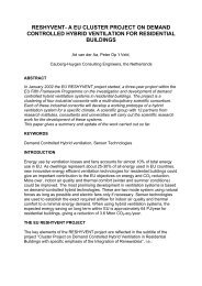
<strong>European</strong> <strong>Green</strong> <strong>Cities</strong> is a targeted EU-Thermie project within the building sector, which<br />
in 1996 received funding of a total of 2.9 million Euro. Cenergia coordinates the project<br />
in cooperation with <strong>Green</strong> City Denmark and the focus on large-scale urban renewal plan<br />
and new building in 11 <strong>European</strong> cities and it will involve close to 30.000 residences. An<br />
important part of the project is to realise local solar energy/low-energy demonstration<br />
project with a total of 645 solar energy/low-energy dwellings in Denmark, France, Spain,<br />
Italy, England, Belgium and Austria and also public buildings in Finland and Greece.<br />
The objective of the <strong>European</strong> <strong>Green</strong> <strong>Cities</strong>, Integrated Quality Target Project is to<br />
introduce an integrated sustainable global solar low-energy design using best available<br />
technologies in new-built and retrofit building projects based on energy and<br />
environmental assessment together with a total energy and total economy approach, e.g.<br />
using new energy saving measures as the background for creating a realistic market for<br />
sustainable and energy efficient building. To ensure that the most cost-effective solutions<br />
are selected, early price calculations will be performed in cooperation with contractors for<br />
all projects.<br />
It is proposed to develop guidelines and establish an early state education process<br />
together with leading institutions in Europe, the target group being city authorities,<br />
builders and consultants focusing at five different selected target action areas:<br />
− Sustainable and healthy building design.<br />
− Energy and environmental assessment incl. total economy assessment.<br />
− Optimised energy and water supply systems.<br />
− Building integrated solar energy design.<br />
− Sustainable urban planning.<br />
Based on this, working groups will be established to define improved energy and<br />
environmental standards for sustainable and energy efficient building including energy<br />
supply systems. Buildings, which meet a certain standard can, based on this, obtain a<br />
”green cities” certificate.<br />
A cooperation with the city of Gdansk and other East and Central <strong>European</strong> cities is also<br />
foreseen in the project in an attempt to transfer project results to East and Central<br />
<strong>European</strong> countries.<br />
Most of the technical solutions that has been used in the <strong>European</strong> <strong>Green</strong> City projects are<br />
well-documented and developed on the basis of research and development. When many<br />
new technologies are used together there are, however, increased technical risks than in<br />
traditional building projects. The new aspect in this projects is to integrate the many<br />
tested technologies in nine different countries to obtain savings of between 40 and 60% of<br />
the energy consumption for heating and domestic hot water and between 30 and 35% of<br />
the electricity and water consumption.<br />
7
EUROPEAN GREEN CITIES<br />
<strong>Final</strong> <strong>Technical</strong> <strong>Report</strong><br />
December 2001<br />
<strong>European</strong> <strong>Green</strong> <strong>Cities</strong> includes demonstration projects in the following <strong>European</strong><br />
cities/countries:<br />
New building:<br />
− Herning, Denmark<br />
− Radstadt, Austria<br />
− Kuopio, Finland<br />
− Vilanova i la Geltrú, Spain<br />
− Hulshout, Belgium<br />
One family houses, Denmark<br />
Renovation:<br />
− Copenhagen, Denmark<br />
− Grenoble, France<br />
− Brescia, Italy<br />
− Regione Abruzzo, Italy<br />
− Volos, Greece<br />
− Portsmouth, England<br />
2.1.1 Abruzzo, Italy<br />
The project will demonstrate how low energy interventions can be introduced with<br />
respect to the original qualities of the existing buildings. The aim is to have an urban area<br />
designed with low energy and environmental criteria starting from introducing Rational<br />
Use of Energy and integration of Renewable Energies in housing blocks with a high<br />
energy consumption, built before 1975.<br />
2.1.2 Brescia, Italy<br />
The aim of the proposal is to show the technical feasibility of energy efficient retrofit in a<br />
building refurbishment project (building scale) and its portability to the city of Brescia.<br />
The aim of this project is not only to save energy and to make Brescia "greener", but also<br />
to improve winter thermal comfort, to avoid summer overheating and to avoid tenants'<br />
nuisances during refurbishment.<br />
8
EUROPEAN GREEN CITIES<br />
<strong>Final</strong> <strong>Technical</strong> <strong>Report</strong><br />
Figure 2.1. Building facade in Brescia after renovation.<br />
2.1.3 Copenhagen, Denmark<br />
Figure 2.2: Photo of the Copenhagen project before renovation.<br />
December 2001<br />
This project in Copenhagen seeks to maximise the use of solar energy and to minimise<br />
the output of CO2 from heating, hot water and electricity use. It is also the aim of the<br />
project to reduce the use of water.<br />
The project is carried out in an area of Copenhagen with many old building blocks. These<br />
old buildings will be renovated in the next years and the Copenhagen project will<br />
demonstrate new energy savings technology.<br />
Many of these old buildings in the centre of Copenhagen have not installations like bath<br />
and heating. The project also demonstrates how to implement new and modern facilities<br />
into old buildings without changing the original architectural design.<br />
It is also the aim of the project to establish good indoor climate with effective ventilation<br />
and by use of material without any emission.<br />
The aim of this project has also been to investigate and demonstrate the efficiency of PV<br />
solar modules installed on both roofs, facades and integrated into the building envelope.<br />
In this project both crystalline and amorphous panels have been used.<br />
The objective of the one family house project is to develop an efficient heat supply<br />
system that corresponds the low heat demand in new energy efficient houses. It is the aim<br />
to develop a cost effective heat distribution system that combines central heating, low<br />
energy housing scheme and cost effective solar energy system for domestic hot water and<br />
space heating. An ordinary distribution network for domestic hot water will be developed<br />
also to supply the houses with space heating.<br />
9
EUROPEAN GREEN CITIES<br />
<strong>Final</strong> <strong>Technical</strong> <strong>Report</strong><br />
December 2001<br />
Ventilation with heat recovery is often used in low energy housing scheme to reduce the<br />
ventilation losses and to secure a high indoor air quality. The ventilation system will be<br />
developed to cover the space heating demand also and then avoid a conventional radiator<br />
installation.<br />
2.1.4 Grenoble, France<br />
Figure 2.3.: Photo of the solar collector on the roof in the Grenoble project.<br />
The project is 505 dwellings retrofit program in Echirolles, a city near Grenoble, in<br />
France.<br />
Urban aspects have been improved, with a new cultural centre and a new tramway line,<br />
and all the dwellings have been retrofitted.<br />
It was the aim to have an energetic performance high level. So, it was decided to use 705<br />
m² solar panels for hot domestic water and 95 m² photovoltaic panels for ventilation and<br />
common light. There was also a total energy approach concerning commons electricity<br />
and heating consumption with insulation.<br />
Social goals<br />
The first aim is social : the first benefit is for the end users. The maintenance costs will<br />
decrease and it is important for the tenants who have often social problems like<br />
unemployment.<br />
It was the aim to demonstrate the renewable energies possibilities to reduce maintenance<br />
costs and external social costs.<br />
Concerning this project, the maintenance cost reduction aim is 80 Euro per dwelling per<br />
year.<br />
The secondly interests are for the OPAC 38 which hope good social effects through the<br />
reduction of maintenance costs : turn over, vacancies and social difficulties reduction.<br />
Environmental aspects<br />
Another important aim is the fight against pollution: renewable energies are one of the<br />
most important potentials to reduce green house effect and pollutants emissions.<br />
2.1.5 Herning, Denmark<br />
In order to optimise the assessment of individual environmental approaches, this project<br />
consists in two similar blocks, one traditional, and one “green”. The aim is thus to<br />
compare the quantity of energy used in the two blocks, each containing 42 apartments for<br />
students.<br />
10
EUROPEAN GREEN CITIES<br />
<strong>Final</strong> <strong>Technical</strong> <strong>Report</strong><br />
December 2001<br />
Eventually the plan is to evaluate the cost/benefit of each choice of environmental<br />
subjects, for future use in other “green” projects.<br />
Figure 2.4.: Photo of the Herning project.<br />
2.1.6 Hulshout, Belgium<br />
Figure 2.5.: Photo of the Hulshout project.<br />
The general objective of social housing companies is to build houses for low-income<br />
people at reasonable costs. Usually, limited attention is paid to energy saving<br />
technologies. Energy saving is, however, important because of the limited family budget<br />
and because of the important share of energy costs in the budget. The project “Energy<br />
efficient and environmentally friendly social houses in Hulshout” will pay special<br />
attention to energy savings and sustainable building at acceptable incremental<br />
construction and installation costs while maintaining a high level of comfort. Energy and<br />
water savings realised, as a result of the project, will improve the quality of life of the<br />
inhabitants.<br />
The aim of the project is to demonstrate an integrated global energy design for 23 new<br />
energy efficient social houses in the municipality of Hulshout. The investor is the social<br />
housing company Zonnige Kempen (Westerlo). The architect of the project is Mr. E.<br />
Maes (Westerlo) and the engineering work is done by Mr. J. Daenen (Bertem). The<br />
project will be closely monitored by the technological research institute Vito (Mol) and<br />
by the building physics laboratories of the university KUL (Leuven).<br />
The objective of the project Hulshout is (1) to reduce the energy use for heating by more<br />
than 70% with respect to standard houses in Belgium, (2) to reduce the energy use for<br />
domestic hot water by 50%, (3) to reduce electricity consumption by 10%, (4) the reduce<br />
water consumption by 30%, and (5) to meet high environmental standards by using<br />
environmentally friendly building materials and by realising water savings based on the<br />
use of rain water, water conserving toilets, …<br />
11
EUROPEAN GREEN CITIES<br />
<strong>Final</strong> <strong>Technical</strong> <strong>Report</strong><br />
2.1.7 Kuopio, Finland<br />
Figure 2.6.: Photo of the school in Kuopio<br />
December 2001<br />
The goal of the project was to experiment and introduce various energy saving techniques<br />
and products in a new construction project situated in the cold northern zone. The<br />
duration of the heating period for the site is about ¾ of a year. There is practically no<br />
need for cooling the rooms. The construction is a public building, primarily intended as a<br />
basic school. The builder and main financier was the city of Kuopio.<br />
Energy conservation was striven towards by insulating the envelope surface of the<br />
building, the base floor, walls and roof as well as the windows to a level above the<br />
standard required by construction regulations, and by implementing new technology in<br />
heating and ventilation and lighting control. An automated building management system,<br />
Local Operating <strong>Net</strong>work (LON) technology was experimented with.<br />
The project did not quite achieve the goals of the energy saving in the consumption of<br />
heat, electricity and water. The experimental construction was still regarded as useful<br />
because new experience was gained on the functionality of new techniques and the city<br />
has been able to implement or adapt them for use in other municipal construction<br />
projects. It is proposed that research and experimenting on the use of solar energy on a<br />
medium scale will be continued.<br />
The goal of the project was to create important energy savings compared to standard<br />
construction practices in building:<br />
− 40 % in heating<br />
− 30 % in electricity<br />
− 20 % in water consumption<br />
Carbon dioxide emissions into the atmosphere in the production and use of energy would<br />
decrease in proportion to the savings achieved.<br />
In Kuopio as with elsewhere in Finland, schools form about a third of the building stock<br />
owned by the municipalities. The utility and maintenance costs of school buildings have<br />
risen continuously as the buildings and equipment age, the number of electrical<br />
appliances increases and energy prices go up. Simultaneously, quality requirements for<br />
indoor air and lighting have risen. The project aims to introduce new standards for<br />
construction planning with higher global goals in new energy-saving technology and in<br />
environmental impact compared to what is common in present investment practice.<br />
2.1.8 Portsmouth, GB<br />
The refurbishment of a high rise block of flats near Portsmouth City centre looks to<br />
demonstrate low energy retrofit measures and utilise a number of energy saving features<br />
designed to reduce energy use and improve the efficiency of energy delivered.<br />
12
EUROPEAN GREEN CITIES<br />
<strong>Final</strong> <strong>Technical</strong> <strong>Report</strong><br />
December 2001<br />
The project includes a number of both conventional and innovative energy efficient<br />
measures:<br />
− Use of a combined heat and power plant in conjunction with a district heating scheme<br />
to absorb the waste heat provided.<br />
− Load management via a Building Energy Management system.<br />
− District heating system with improved efficiency resulting from reduced distribution<br />
losses and reduced pumping costs.<br />
− Electricity savings to tenants resulting from the removal of electric water heating and<br />
replacement with district heating. Low electricity use for ventilation and lighting.<br />
− Improved insulation brought about by replacing windows with double glazing,<br />
external cladding and provision of pitched insulated roofs to replace the existing flat<br />
roof.<br />
− Improved ventilation with heat recovery systems from extracted stale air.<br />
− PV modules for generation of electrical power serving heat recovery ventilation fans.<br />
− Solar DHW heating to 8 no flats.<br />
The project demonstrates an energy efficient refurbishment in the city centre as part of a<br />
programme designed to ‘green’ the city environment. Portsmouth promotes an energy<br />
and environment policy commitment to the development of ‘green’ technologies such as<br />
combined heat and power and renewables<br />
Figure 2.7: CAD image of new cladding and windows to East/West Elevations<br />
2.1.9 Radstadt, Austria<br />
The new building project Radstadt-West consists of three houses with 36 dwellings and is<br />
one part of a bigger program to reactive the part of the city Radstadt-West. Other parts are<br />
a traffic concept, a new green-area planning and the renovation of five houses from the<br />
40ties. As a new way in social housing-construction, the local project committee decided<br />
to charge a study of an economic and ecological analysis of the project. The study was<br />
done by Dr. Manfred Bruck and Dr. Harald Koch from Vienna in co-operation with the<br />
Architect.<br />
Therefor 10 different variants of construction and heating systems have been analysed<br />
relating to their ecological effects.<br />
The study consists of two parts:<br />
13
EUROPEAN GREEN CITIES<br />
<strong>Final</strong> <strong>Technical</strong> <strong>Report</strong><br />
December 2001<br />
In the economic part the lifecycle costs of the project (raw material, construction,<br />
maintenance and demolition) have been calculated.<br />
In the ecological analysis the environmental effects of the different variants have been<br />
investigated. Further the use of primary energy, the contribution to the global warming<br />
potential and the sour of ground was calculated.<br />
According to the results of this study it was possible to find the best combination of<br />
construction, material and heating system. With this combination it is possible to preserve<br />
the environment and to promote renewable sources of energy without a reduction of the<br />
users living comfort and keeping the rates low.<br />
Figure 2.8.: Photo of the project in Radstadt.<br />
2.1.10 Vilanova, Spain<br />
The project aims to demonstrate the feasibility of incorporating high environmental<br />
quality standards and a rational use of energy to social housing buildings, before applying<br />
them to more constructions in the city.<br />
Figure 2.9: Building under construction in February 2000.<br />
14
EUROPEAN GREEN CITIES<br />
<strong>Final</strong> <strong>Technical</strong> <strong>Report</strong><br />
December 2001<br />
The innovative technologies developed in the project, from the Spanish market point of<br />
view, can be summarised in three main areas of development:<br />
− Heating and domestic hot water based on solar energy and natural gas.<br />
− Bioclimatic and low energy building design.<br />
− Sustainable design regarding the use of materials and water management.<br />
Figure 2.10: Picture of the project in Vilanova i la Geltrú, January 2001<br />
The interest of the measures applied in the Project, in the context of the Spanish market,<br />
is related to:<br />
− The type of development - social housing,<br />
− The innovative service approach,<br />
− The energy efficient solutions,<br />
− The use of renewable energies,<br />
− The improvement of the comfort conditions in summer and winter by bioclimatic<br />
criteria<br />
Other technologies and environmentally positive approaches without the EU support, but<br />
which have been included in the project are:<br />
• Bioclimatic and, low energy design by considering orientation, openings and<br />
dimensions:<br />
- Cross ventilation and natural light.<br />
- Solar protections by overhangs.<br />
• Environmentally friendly construction materials:<br />
- Eco-brick high-insulation materials<br />
- Electrical installation without PVC.<br />
• Domestic water saving appliances<br />
• Ecological paint<br />
2.1.11 Volos, Greece<br />
In the framework of the THERMIE programme the Demekav/Rect was funded for the<br />
realization of energy saving applications in rehabilitated municipal buildings. Four<br />
industrial buildings of a reputed historical brick and tile factory (“Tsalapatas” factory)<br />
and one grain sanitation building were transformed in modern high energy efficiency<br />
bioclimatic buildings satisfying public purposes (museum, cinema, exposition hall, video<br />
wall room, Regional Energy Center, etc.). Direct solar thermal applications, solar water<br />
heating collectors, insulation, summer shading, passive solar ventilation (e.g. solar<br />
chimneys), double glazing, light penetration enhancement, etc. are some of the<br />
applications realized. Partial energy savings of up to 70% are expected compared to the<br />
initial state of the buildings. A very important replication effect is also expected from<br />
15
EUROPEAN GREEN CITIES<br />
<strong>Final</strong> <strong>Technical</strong> <strong>Report</strong><br />
December 2001<br />
those applications, because of the experience gained by local engineers and of the very<br />
high demonstrative value of the buildings in which they have been realized.<br />
after<br />
Figure 2.11.: The old grain sanitation building (before) transformed to the new<br />
bioclimatic building hosting the Regional Energy Center of Thessaly (after).<br />
2.2 Description of the Sites<br />
The <strong>EGC</strong> projects include building projects in Europe from Greece in south to Finland in<br />
the North. The climate is very different from the mild and sunny weather in south to the<br />
cold weather in the north. It raises different demand to the insulation of the building<br />
envelope and the energy savings technologies have different benefit depending on the<br />
location. The performance of a solar system is higher in the southern countries and the<br />
design has to be designed to the specific location. The numbers of heating degree-day in<br />
the <strong>EGC</strong> projects are given in Figure 2.12. The heating degree-day of Austria is not<br />
available because of very big difference between locations.<br />
Volos, Greece<br />
Vilanova, Spain<br />
Radstadt, Austria<br />
Portsmouth, GB<br />
Kuopio<br />
Hulshout<br />
Herning<br />
Grenoble<br />
Copenhagen<br />
Brescia<br />
Abruzzo<br />
Heating Degree Days<br />
0 1000 2000 3000 4000 5000 6000<br />
Degree Days<br />
Figure 2.12.: Heating degree-days in the <strong>EGC</strong> projects according to norms.<br />
16
EUROPEAN GREEN CITIES<br />
<strong>Final</strong> <strong>Technical</strong> <strong>Report</strong><br />
2.2.1 Abruzzo, Italy<br />
December 2001<br />
The global retrofit project consists of 2 buildings for total 54 apartments located in “La<br />
Pulcina” area in a small Italian town called Avezzano.<br />
Table 2.1.: Meteorological data for project.<br />
Abruzzo<br />
Latitude 42°01’<br />
Altitude 695 m<br />
Average global radiation 3.99 kWh/m²/day<br />
Average degree days 2561<br />
Design heating temperature - 5 °C<br />
2.2.2 Brescia, Italy<br />
The Brescia project is located in the city of Brescia in Via Tiziano.<br />
Table 2.2.: Meteorological data for project.<br />
Brescia<br />
Latitude 45°32’<br />
Altitude 149 m<br />
Average global radiation 3.76 kWh/m²/day<br />
Average degree days 2410<br />
Design heating temperature -7<br />
2.2.3 Copenhagen, Denmark<br />
The Copenhagen project consists of three buildings, which make part of a courtyard with<br />
totally 360 dwelling, called Hedebygade. The Copenhagen project also include a housing<br />
scheme in Rødekro with a cost effective low energy design.<br />
Table 2.3.: Meteorological data for Copenhagen project.<br />
Copenhagen<br />
Latitude 55°46’<br />
Altitude 19 m<br />
Average global radiation 2.78 kWh/m²/day<br />
Average degree days 3178<br />
Design heating temperature - 12 °C<br />
The projects are:<br />
Tøndergade 3-3A<br />
17
EUROPEAN GREEN CITIES<br />
<strong>Final</strong> <strong>Technical</strong> <strong>Report</strong><br />
Tøndergade/Sundevedsgade<br />
The building is on the corner of<br />
Sundevedsgade and Tøndergade and is<br />
from 1880 and has five stories. The facade<br />
facing the street has kept the original<br />
architectural design. The building include<br />
21 dwellings and a restaurant on ground<br />
floor.<br />
The facade facing the courtyard has<br />
changed completely. The ventilation units<br />
with heat recovery are installed outside the<br />
facade and covered by glass and PVmodules.<br />
Sundevedsgade 26-28<br />
The building is from 1880 and has 5<br />
storeys, before the renovation there was<br />
only one layer of glazing. The apartments<br />
were heated individually (electricity, gas,<br />
and petroleum) and are now supplied with<br />
district heating.<br />
Facade to the courtyard with two rows of<br />
PV-modules between big window area to<br />
utilise passive solar and daylight.<br />
December 2001<br />
18
EUROPEAN GREEN CITIES<br />
<strong>Final</strong> <strong>Technical</strong> <strong>Report</strong><br />
One family house<br />
Energy optimised retrofit for one family<br />
house in Virum near Copenhagen.<br />
Byskoven<br />
The high efficient distribution system is<br />
demonstrated in a social housing scheme in<br />
Rødekro in south of Jutland near the<br />
German border. The project includes total<br />
90 low energy houses.<br />
December 2001<br />
The size of the buildings and the floor area per building unit are illustrated in the table<br />
below.<br />
Building block Number of units Total floor area Average floor area<br />
(units)<br />
(m²)<br />
(m²/unit)<br />
Tøndergade 3-3A 20 1040 52.0<br />
Tøndergade/Sunde<br />
vedsgade<br />
20 1137 56.9<br />
Sundevedsgade 21 1201 57.2<br />
Byskoven 57 4845 85.0<br />
Total 117 8223 70.3<br />
2.2.4 Grenoble, France<br />
The dwellings are divided into three groups corresponding to three district heating rooms.<br />
The size of these groups and the floor areas are illustrated in the table below.<br />
Building group Number of units Total floor area Average floor area<br />
(units)<br />
(m²)<br />
(m²/unit)<br />
Berry 190 13 765 72,4<br />
Beaumarchais 1 193 14 105 73,1<br />
Beaumarchais 2 122 8 826 72,3<br />
Total 505 36 696 72,7<br />
Number of inhabitants 1308<br />
Table 2.4.: Meteorological specifications of the project. The global solar radiation on<br />
horizontal (kWh/m²) is monitored on a nearby weather station called Saint Martin<br />
d’Hères. The calculation of the degree days are based on 18°C.<br />
19
EUROPEAN GREEN CITIES<br />
<strong>Final</strong> <strong>Technical</strong> <strong>Report</strong><br />
Grenoble<br />
Latitude 45°40’<br />
Altitude 220 m<br />
Average global radiation 3,61 kWh/m²/day<br />
Average degree days 2688<br />
Design heating temperature - 10 °C<br />
2.2.5 Herning, Denmark<br />
December 2001<br />
The Herning project consists in 2 new similar buildings situated in a former industrial<br />
area, close to Herning City and railway-station. The urban plan is to convert a larger<br />
elderly industrial area in to a resident area within a timeframe of 10 years. Our buildings<br />
in Tietgensgade is the second project in this area, and the next is scheduled to year 2003,<br />
also apartments for students.<br />
Figure 2.13.: Photo of the Herning project.<br />
There are a total of 84 apartments, 48 apartments with bath and kitchen/room (33 m2),<br />
and 36 apartments with bath, kitchen/room and a room (48 m2), with a total of 3299 m2,<br />
plus basement 369 m2 (laundry, assembly hall, engineering room, and two study-rooms)<br />
and app. 120 tenants.<br />
2.2.6 Hulshout, Belgium<br />
The project in Hulshout consists of 23 new energy efficient social houses. The building<br />
project consists of three blocks of respectively 3, 12 and 8 building units. The size of the<br />
buildings and the floor area per building unit are illustrated in the table below.<br />
Building block Number of units<br />
(units)<br />
Total floor area<br />
(m²)<br />
Average floor area<br />
(m²/unit)<br />
20
EUROPEAN GREEN CITIES<br />
<strong>Final</strong> <strong>Technical</strong> <strong>Report</strong><br />
1 3 351 117<br />
2 12 1231 103<br />
3 8 620 78<br />
Total 23 2202 96<br />
December 2001<br />
Table 2.5.: Meteorological specifications of the project. The degree days are based on<br />
15°C.<br />
Hulshout<br />
Latitude 50°48<br />
Altitude<br />
Average global radiation 2.65 kWh/m²/day<br />
Average degree days 1923<br />
Design heating temperature -10<br />
2.2.7 Kuopio, Finland<br />
Figure 2.14.: Photo of the experimental solar wall.<br />
The Pirtti school is the third new school in the southern suburb of Kuopio, in the Pirtti<br />
district within the Petonen area. It is situated 10 km south from the centre of the city.<br />
Petonen is the most important expansion zone of the city, with a target population of<br />
15,000 in 2005. City planning aims to exploit the best features of the natural surroundings<br />
and to combine these with the ideas of a traditional city. <strong>Technical</strong> service networks such<br />
as district heating, water and sewage lines and cable TV had been extended to the<br />
residential area surrounding the construction site prior to the residential construction.<br />
Table 2.6.: Meteorological specifications of the project.<br />
Kuopio<br />
Latitude 62°00<br />
Altitude<br />
Average global radiation 2.54 kWh/m²/day<br />
Average degree days 5045<br />
Design heating temperature<br />
The goal of the project was to try out, introduce and develop energy-effective planning,<br />
construction and equipment in a new construction project in Kuopio. The project was a<br />
public building, a basic school for a new residential area. The school was intended<br />
21
EUROPEAN GREEN CITIES<br />
<strong>Final</strong> <strong>Technical</strong> <strong>Report</strong><br />
December 2001<br />
originally as a school for grades 1-6, but as different school grades are united, it may also<br />
house teaching for the secondary school, grades 6-9.<br />
The project included modern architecture, durable materials that are advantageous for the<br />
indoor air and have low emission levels, and advanced automated building management<br />
combined with the school construction. A basic school was chosen for the experimental<br />
construction project because schools are an important group of buildings within local<br />
government property management in the public sector, in respect of new construction<br />
work, basic repairs, maintenance and utility costs.<br />
2.2.8 Portsmouth, GB<br />
The tower block, Leamington House, was constructed in the 1970’s and is a 17 story high<br />
‘Bison’ large panel system design building located in the City Centre of Portsmouth. It<br />
has a twin building, Solihull House, which is not being refurbished and can therefore<br />
provide a comparison in the monitoring programme.<br />
Table 2.7.: Meteorological specifications of the project.<br />
Portsmouth<br />
Latitude 50°00’<br />
Altitude<br />
Average global radiation 3.02 kWh/m²/day<br />
Average degree days 2194<br />
Design heating temperature -3<br />
Figure 2.15: Work in progress photo of Leamington House. It is 17 stories with one, two<br />
and three bedroom flats. Photo taken from Solihull House. Boiler House is at bottom left<br />
under the car park shown.<br />
The block has one, two and three bedroom flats located on each floor with communal<br />
areas and storerooms located on the ground floor. The block is having a public laundry<br />
installed as part of the refurbishment.<br />
2.2.9 Radstadt, Austria<br />
Radstadt is an old city 75km south of Salzburg, in the centre of Austria. It has about 4700<br />
inhabitants. Radstadt has its city-rights since 1289. The old citywall from the 13th century<br />
22
EUROPEAN GREEN CITIES<br />
<strong>Final</strong> <strong>Technical</strong> <strong>Report</strong><br />
December 2001<br />
is completely preserved. The economy is mainly agricultural and touristic, in summer for<br />
hiking, golf and mountainbiking and in winter it is a very famous skiing-area.<br />
The western part of the city Radstadt was in spite of a good site and infrastructure not<br />
integrated in the development of the centre in the last years.<br />
The community has decided to change this situation. Architect Heiner Hierzegger from<br />
Graz was asked to draw up a town-planning study of this area to show the possibilities of<br />
development.<br />
On a free area of about 4.400 m² it is intended to build dwellings, as the first part of a<br />
dwelling program for this part of the city. Until now this area was used as a parking lot.<br />
For the area beside a second part of the dwelling project is planned. Nearby there is an<br />
old housing-estate, that shall be renovated.<br />
The project was chosen by the government of Salzburg to be the first "Modellwohnbau"<br />
of the country of Salzburg – a project, that shall bring best living quality by considering<br />
aspects of ecology, energy, architecture and economy. The SIR is charged with the coordination<br />
and moderation of this project.<br />
In 1993 there was an official architectural competition. Architect Hanns Peter Köck from<br />
Saalfelden won the first price. He was charged with the develop-planning and the detailed<br />
planning of the new dwellings.<br />
The whole project consists about 50 dwellings. In the first part 36 dwellings will be built,<br />
30 shall be for rent and 6 shall be for sale.<br />
Table 2.8.: Meteorological specifications of the project.<br />
Radstadt<br />
Latitude 47°05’<br />
Altitude 850 m<br />
2.2.10 Vilanova, Spain<br />
The project concerns an 80 bioclimatic apartment building in Vilanova i la Geltrú, 60 km<br />
south of Barcelona City. It is the first step of a bigger development that will account for<br />
up to 1.332 dwellings.<br />
Figure 2.16: Close view of a finished building in El Llimonet, January 2001<br />
23
EUROPEAN GREEN CITIES<br />
<strong>Final</strong> <strong>Technical</strong> <strong>Report</strong><br />
December 2001<br />
The 80 individual flats form a single building and are either 70m 2 or 90m 2 . The ground<br />
floor is dedicated to commercial activity and underground car parking has also been<br />
constructed.<br />
Table 2.9.: Meteorological specifications of the project (Data Source: Servei de<br />
Meteorologia de la Generalitat de Catalunya).<br />
Vilanova<br />
Latitude 41°20’<br />
Altitude 14 m<br />
Average global radiation 4.03 kWh/m²/day<br />
Average degree days 1235<br />
Design heating temperature<br />
2.2.11 Volos, Greece<br />
This project concerns energy saving interventions realized in the following four<br />
rehabilitated buildings of the municipality of Volos:<br />
− Three buildings of an old brick and tiles factory (‘ Tsalapatas’ factory). Two brick<br />
drying stores and the Kiln.<br />
− An ex grain sterilization hangar of the Ministry of Agriculture.<br />
Both cases had some particular interest. The three industrial buildings of the old factory,<br />
were subject to restrictions by the Ministry of Culture, since they have been characterized<br />
as parts of our Cultural Heritage. The fourth building was interesting because its initial<br />
state and use were by far incompatible to the final ones and a lot of imagination was<br />
needed.<br />
Table 2.10.: Meteorological specifications of the project.<br />
Volos<br />
Latitude 39°40<br />
Altitude 3<br />
Average global radiation 4.7kWh/m²/day<br />
Average degree days 1350<br />
Design heating temperature -3°C<br />
Figure 2.17: The bioclimatic building of a total of 530 m 2<br />
24
EUROPEAN GREEN CITIES<br />
<strong>Final</strong> <strong>Technical</strong> <strong>Report</strong><br />
December 2001<br />
The brick & tiles factory “Tsalapatas” is situated in the neighborhood of Palaia, west side<br />
of the castle of the city of Volos. It was established in 1925 from Tsalapatas brothers and<br />
operated until 1975.<br />
It includes a group of industrial buildings of 7600 m 2 and shed places of 4900 m 2 , in a<br />
land of 22,65 thousand m 2 inside the urban area of the city (fig. ). It is a very rare sample<br />
of preserved industrial complex of its kind in Europe. Has a unique kiln Hoffmann type<br />
and preserved elements of production methods from steam engines to electricity of today.<br />
The Ministry of Culture in Greece preserves the whole complex as Culture Heritage.<br />
The grain sanitation building is located in the south-west part of the city and was owned<br />
by the Ministry of Agriculture. Sanitation was realized by fumigation using methyl<br />
bromide. The operation of the site ceased in 1975 and remained closed for 20 years.<br />
<strong>Final</strong>ly in 1995, the building was granted to the Municipality of Volos, for 20 years, in<br />
the state shown in figure (before).<br />
The building was in such a state that it could not be imagined that it could serve any other<br />
purpose. However, the imagination of local architects and engineers transformed this<br />
building to the state shown in figure (after), incorporating in it several elements of<br />
modern bioclimatic design.<br />
From August 2000, the bioclimatic building of a total of 530 m 2 , shown in Figure 2.17<br />
(after), hosts the Regional Energy Center of Thessaly and a total of 16 persons are now<br />
working in it.<br />
2.3 Description of the Installation<br />
Table 2.11.: Overview of the energy savings technologies in <strong>EGC</strong> projects.<br />
Energy Savings Technology<br />
Low energy windows x x x x x x x x x x<br />
Extra wall insulation x x x x x x x x x x x<br />
Solar heating for DHW x x x x x x x x x x<br />
Solar heating for SH x x<br />
Passive solar x x x x x x x x x<br />
Improved daylight x x x x<br />
Centralised heating system x x x x x x x x<br />
Condensing gasboilers x x<br />
Combined heat and power x x x x<br />
Individual heating control x x x x x x x x x<br />
Natural ventilation x x<br />
Mechanical ventilation x x x x x x x<br />
Mechanical ventilation with preheating of air x x<br />
Mechanical ventilation with heat recovery x x x x x x<br />
PV modules x x x x x<br />
Individual heat meters x x x x x x x<br />
Individual water meters x x x<br />
Water savings x x x x x<br />
Electricity savings x x x x x x x x x x x<br />
BEMS x x x x x x x x x<br />
An overview of the low energy savings technologies used in the <strong>EGC</strong> projects are given<br />
in Table 2.11. All the projects have higher insulation standard of the building envelope<br />
Abruzzo<br />
Brescia<br />
Copenhagen<br />
Grenoble<br />
Herning<br />
Hulshout<br />
Kuopio<br />
Portsmouth<br />
Radstadt<br />
Vilanova<br />
Volos<br />
25
EUROPEAN GREEN CITIES<br />
<strong>Final</strong> <strong>Technical</strong> <strong>Report</strong><br />
December 2001<br />
compared to the national building regulations. Also windows and the ventilation have<br />
been improved.<br />
The specific heat losses (W/°C) of a standard building of 100 m² are calculated with the<br />
Thermie specifications used in the projects and the results are given in Figure 2.18. The<br />
calculated values include transmission losses through external surfaces and from<br />
ventilation.<br />
Volos, Greece<br />
Vilanova, Spain<br />
Radstadt, Austria<br />
Portsmouth, GB<br />
Kuopio<br />
Hulshout<br />
Herning<br />
Grenoble<br />
Copenhagen<br />
Brescia<br />
Abruzzo<br />
Specific Heat Losses<br />
0.0 50.0 100.0 150.0 200.0 250.0 300.0<br />
Figure 2.18.: Calculated specific heat losses using the actual Thermie specifications of<br />
each <strong>EGC</strong> projects.<br />
2.3.1 Abruzzo, Italy<br />
Window replacement<br />
946 m 2 of windows have been replaced of which 852 m 2 with a thermal cut steel frame<br />
and low energy glasses with U-value = ≈ 2.0 W/m²Kn have been installed.<br />
The reduction of the U-value of the windows from 5,8 to 2 W/m 2 K permitts the reduction<br />
of the building total thermal losses from 396000 to 136000 kWht/year with an energy<br />
saving of about 260000 kWht/year (66%).<br />
External walls insulation<br />
External insulating coat of the building envelope by means of polystyrene panels<br />
(conductivity = 0,035 W/mK):<br />
W/°C<br />
External walls: 5390 m² - 60 mm of polystyrene panels<br />
First floor: 1195 m² - 30 mm of polystyrene panels<br />
Last floor under the roof: 1195 m² - 40 mm of polystyrene panels<br />
The intervention produced a reduction of energy consumption of 191000 kWh/year with<br />
an energy saving of 323000 kWh/year.<br />
26
EUROPEAN GREEN CITIES<br />
<strong>Final</strong> <strong>Technical</strong> <strong>Report</strong><br />
December 2001<br />
This action has been very efficient because the buildings were built before the Italian Law<br />
about energy saving (Law n. 373/76) and the building envelopes were characterised by<br />
high thermal losses.<br />
The U-values of the building:<br />
floor 0.71 W/m²K<br />
roof 0.56 W/m²K<br />
Windows 2.00 W/m²K<br />
External wall 0,24 W/m²K<br />
Solar collectors for DHW production<br />
A Solar heating system for DHW production was installed:<br />
− 9 solar units of 15 m² each for a total surface of 135 m² (tilt = 30°).<br />
− Each solar unit serves a stair of 6 apartments<br />
− Each solar unit is provided with a local storing heat exchanger (600 lt) heated by<br />
solar energy and auxiliary heat produced by a furnace during the heating season, by<br />
solar energy and electricity as auxiliary in the summer period.<br />
− Satellitar units (“modusat”) have been installed in each apartment and these<br />
accomplish the same task of the original autonomous boilers, being supplied both by<br />
the solar units and the centralised boiler.<br />
Figure 2.19. Water solar collectors on the roof.<br />
New centralised heating system<br />
The new centralised heating system consists in a high efficient condensing multicells<br />
furnace (6 modules of 50 kWt each, parallel connected). The thermal power of the<br />
multicells furnace is variable from 10 to 300 kWt.<br />
27
EUROPEAN GREEN CITIES<br />
<strong>Final</strong> <strong>Technical</strong> <strong>Report</strong><br />
Figure 2.20. Multicells furnace<br />
The main consequences of the modified heating system are:<br />
− Centralised heat production for space heating and DHW production<br />
− Autonomous management for each apartment<br />
− Individual energy consumption metering<br />
December 2001<br />
− The existing radiators, actually over-sized comparing with the heat demand of the<br />
rooms, because of the improvement of the building insulation permits to supply the<br />
radiators with a low water temperature (45°C) and this turns to the advantage of the<br />
thermal efficiency of the condensing boiler.<br />
Heat meter for each apartment<br />
Each modusat was provided with a heat meter connected to the EMS.<br />
The main objectives are:<br />
− the partition of the fuel costs on the base of the real consumption; solar energy is<br />
considered as free energy for all the apartments.<br />
− The measurement of the energy consumption both for space heating and for DHW<br />
production<br />
− The Acquisition of data about energy consumption by the telemonitoring system<br />
(EMS).<br />
Thermostatic valves on radiators<br />
Thermostatic valves have been installed on each radiator.<br />
The existing radiators have been susituted with aluminium ones, in order to install the<br />
thermostatic valves.<br />
The main consequence is the automatic regulation of the water flow in the radiators on<br />
the base of a fixed temperature in the room.<br />
PV modules<br />
Photovoltaic modules for electricity production from solar energy have been placed on<br />
the roof of one of the building (building No. 1317, 30 apartments): the total PVM surface<br />
is 10 m² and the system is sized for a pick power of 1 kW. An inverter changes the direct<br />
current produced by PV modules in alternate current and the produced electricity will<br />
cover electric demand of the pumps of two solar units. A batteries system (12 lead-acid<br />
accumulators) has been installed to guarantee the working of the PV system also in less<br />
sunny days.<br />
28
EUROPEAN GREEN CITIES<br />
<strong>Final</strong> <strong>Technical</strong> <strong>Report</strong><br />
December 2001<br />
The produced electricity will cover electric demand of the pumps of two solar units.<br />
EMS<br />
An energy management system (EMS) to which each local energy meter is connected was<br />
realised. A central unit is connected to a computer located in an office of ATER of<br />
L’Aquila, to store and to analyse data collected referring to a monitoring programme<br />
selected by the user. The EMS was designed to accomplish the following important<br />
functions:<br />
− To permit an autonomous management of the energy consumption of each apartment<br />
− To acquire all data for the continuous monitoring of each plant system (solar plant,<br />
PV system, condensing multicells furnace).<br />
− To provide expected performance<br />
− To guarantee it for the total lifetime.<br />
2.3.2 Brescia, Italy<br />
New low-energy windows<br />
New low-energy windows with special insulating external frame have been installed: two<br />
glass layers 4 mm thick with a 9 mm air gap with U = 2,732 W/m²K.<br />
The special insulating external frames permit to eliminate the thermal bridges and to<br />
facilitate the junction between wall cladding and windows.<br />
External wall insulation<br />
The intervention consists in improving the insulation characteristics of the building<br />
envelope by means of the following actions:<br />
External insulating coat of the external walls: 5 cm polyurethane foam panel - U = 0,32<br />
W/m²K<br />
Floor insulation: 5 cm polystyrene foam panels<br />
Roof insulation: insulation improvement U = 0,32 W/m²K<br />
The main consequence is the elimination of the existing thermal bridges with an efficient<br />
external walls insulation as more homogeneous as possible.<br />
Table of the building insulation interventions:<br />
PROJECT<br />
Elements Type U (W/m²K)<br />
External Walls on loggias Prefabricated panels 0.322<br />
External Wall Prefabricated concrete panels 0.321<br />
External Wall (closed loggias) Insulated concrete panels 0.570<br />
Load-carrying members Insulated concrete structure 0.549<br />
Floor type 1 Insulated concrete floor 0.549<br />
Floor type 2 Insulated concrete floor 0.298<br />
Buildings roofs Insulated concrete roof 0,342<br />
Apartment roof type 1 Insulated roof 0,370<br />
Apartment roof type 2 Insulated roof 0.298<br />
Passive solar design<br />
29
EUROPEAN GREEN CITIES<br />
<strong>Final</strong> <strong>Technical</strong> <strong>Report</strong><br />
December 2001<br />
Existing loggias on the south facade have been equipped with external windows frames<br />
with a “fan” opening which allow the use of them during winter as sun-space and a<br />
consequent improving of thermal comfort of the near living room. During summer period,<br />
the conservatory can be completely opened and darkening systems are in function.<br />
The conservatories are used as sun-space and the intervention permits the improvement of<br />
improving of thermal comfort of the near living room during winter.<br />
DHW combined solar and district heating<br />
A solar heating plant for the DHW production was integrated with the actual heating<br />
system connected to the district heating network. The project provided the elimination of<br />
centralised DHW production, foreseeing two local storing heat exchangers installed in<br />
three common rooms at the first floor of each block, supplied by district heating, during<br />
winter, and by solar system during the summer period. The local storing heat exchangers<br />
serve all the apartments of the related block. In each local storing room two heat storing<br />
tanks have been located. The volume of the storage tanks and the collector area are given<br />
in the following table:<br />
Solar Storage Collector<br />
Block Tank 1 Tank 2 Area<br />
Block 1 4000 litre 2000 litre 97 m²<br />
Block 2 4000 litre 2000 litre 102 m²<br />
Block 3 3000 litre 1500 litre 62 m²<br />
The intervention included the refurbishment of the three thermal central heating in order<br />
to make it in line with recent Italian regulations regarding electrical and mechanical<br />
plants security.<br />
Figure 2.21. Solar collector on the roof.<br />
The solar system is provided with an automatic regulation and monitoring system of the<br />
temperatures; this is a DDC type too and is connected to the central unit of the EMS.<br />
Mechanical ventilation system<br />
It has been foreseen to provide the building blocks with a mechanical ventilation system:<br />
the intervention was not eligible but it was considered necessary because of the extra<br />
insulation of the building envelope after the Thermie interventions.<br />
The ventilators have been located on the roof of the three building blocks together with<br />
the solar panels.<br />
30
EUROPEAN GREEN CITIES<br />
<strong>Final</strong> <strong>Technical</strong> <strong>Report</strong><br />
December 2001<br />
The objective is to control the air change of the rooms in consequence of the high<br />
insulation characteristics of the buildings (0,5 ÷ 0,7 Vol./h in each room and 6 Vol./h in<br />
the bathroom without windows).<br />
The intervention was not eligible.<br />
Local energy meters<br />
The buildings were originally provided with an obsolete technology of energy metering<br />
system so they have been provided with a new improved system in line with <strong>European</strong><br />
standard and with the possibility to communicate with Energy Management System.<br />
Each apartments is provided with:<br />
− energy metering system<br />
− volumetric metering system for hot and cold water metering<br />
− new heat detector with timer in order to control internal temperature.<br />
The energy meters permit to display energy consumption of each apartment:<br />
− space heating<br />
− solar domestic hot water production<br />
− domestic hot water supplied by district heating.<br />
All energy metering will be connected with the central energy management system.<br />
EMS<br />
The system is DDC type (direct digital control) and it consists in single autonomous<br />
peripheral units connected to a central unit by a communication bus.<br />
The central unit manages a communication register with head control and each apartment.<br />
All energy metering are connected with the main unit and are able to share energy<br />
consumption.<br />
The solar heating plant is provided with an automatic regulation and monitoring system<br />
connected to the EMS.<br />
The central unit is provided with a software for the operator interface.<br />
The central unit is connected to a computer located in the office of ALER Brescia, in<br />
order to storage and analyse data collected according to a monitoring program selected by<br />
the user.<br />
2.3.3 Copenhagen, Denmark<br />
The following innovative elements are used in the project:<br />
Tøndergade 3-3A<br />
− Low energy windows<br />
− Ventilation with heat recovery.<br />
− PV-modules<br />
− Preheating of ventilation air<br />
− Energy meters for SH and DHW<br />
− Flow meters for sanitary water<br />
Tøndergade/Sundevedsgade<br />
− Low energy windows<br />
31
EUROPEAN GREEN CITIES<br />
<strong>Final</strong> <strong>Technical</strong> <strong>Report</strong><br />
− Ventilation with heat recovery<br />
− PV-modules<br />
− Preheating of the ventilation air<br />
− Air solar collector for space heating and domestic hot water<br />
− Hydraulic board for DHW<br />
− Building energy management system<br />
Sundevedsgade 26-28<br />
− Low temperature heating with centrally situated radiator.<br />
− Double frame window system with low energy glass<br />
− Ventilation with heat recovery<br />
− Solar preheating of the ventilation air<br />
− Improved daylight conditions<br />
− Solar collector system on the roof for DHW<br />
− Energy meters for SH and DHW<br />
− Flow meters for sanitary water<br />
Space heating<br />
December 2001<br />
The tree buildings are heat supplied from a district heating system, with a branch into a<br />
boiler room in each building.<br />
Figure 2.22.: Photo of the buffer storage in the boiler room.<br />
The project uses a low temperature heating system, this means that the water<br />
temperatures in the piping system and radiators will be lower than in a conventional<br />
heating system. Therefore the radiators and the piping system should be based on an<br />
increased surface area than in conventional system. Radiators are controlled by<br />
thermostatic valves and placed in the centre of the dwellings. The central location gives<br />
lower installation costs and lower heating losses.<br />
PV-modules and passive solar<br />
All tree projects in Copenhagen have PV-modules integrated in the building facade as<br />
part of a special PV initiative concerning this aiming at preheating ventilation air in the<br />
PV-modules in co-operation with local architects.<br />
Tøndergade 3-3A<br />
Amorphous modules are placed as an integrated part of a facade renovation of the south<br />
facade of the building. The modules are placed under the windows. In this project, the use<br />
of PV is also combined with a ventilation strategy for forced ventilation, where air for<br />
32
EUROPEAN GREEN CITIES<br />
<strong>Final</strong> <strong>Technical</strong> <strong>Report</strong><br />
December 2001<br />
ventilation is pre-heated behind the panels. The ventilation system has heat recuperation<br />
and low energy ventilator fans. The pre-heated air is taken in behind the PV panels.<br />
The total area of the PV-modules is 32m² with total peak power of 1.34 kWp.<br />
There are facade integrated sunspaces to the south.<br />
Tøndergade/Sundevedsgade<br />
A general low energy retrofit design has been developed for urban renewable incl. special<br />
development of optimised daylighting for the old flats.<br />
For 8 apartments the used individual heat recovery ventilation systems was made with a<br />
special design so it also functioned as an air heating system.<br />
PV-modules were integrated in facades in combination with optimised sunspaces.<br />
Sundevedsgade 26-28<br />
The PV-modules are semi-transparent monocrystalline modules placed vertical on the<br />
staircase facade facing the courtyard. The orientation of the modules is south/west. The<br />
PV-modules are ventilated in the air gab between modules and the wall and the preheated<br />
air, entrance into to the staircase. The air flow through the staircase is forced be natural<br />
ventilation.<br />
The total area of PV-modules is 39m² with a total peak power of 3 kWp.<br />
33
EUROPEAN GREEN CITIES<br />
<strong>Final</strong> <strong>Technical</strong> <strong>Report</strong><br />
December 2001<br />
Figure 2.23.: Photo of the semi-transparent monocrystalline modules placed vertical on<br />
the staircase.<br />
Solar heating System<br />
Tøndergade/Sundevedsgade<br />
The solar heating system is a combined system for domestic hot water and space heating.<br />
The solar collector is an air collector type. The solar heat from the collector is transferred<br />
to an air/water heat exchanger placed in the roof space. A water piping system transfer<br />
the solar heat to a buffer storage in the boiler room located in the basement. The<br />
advantages of using air collector are that there are no problems with freezing or boiling.<br />
Sundevedsgade 26-28<br />
The solar heating system is designed for<br />
domestic hot water. The solar collector is a<br />
roof integrated system (see the photo to the<br />
right). A storage tank of 1.6 m³ is located in<br />
the boiler room on the ground floor. The<br />
piping between the collector and storage<br />
tank goes through an old chimney, which is<br />
not used anymore.<br />
Ventilation<br />
Tøndergade 3-3A<br />
The ventilation system with heat recovery is installed in the loft space and each unit<br />
covers 10 dwellings. The ventilation unit includes a cross flow heat exchanger.<br />
Tøndergade/Sundevedsgade<br />
The ventilation of the building include low energy heat recovery DC ventilation systems,<br />
supplied with electricity from PV modules integrated in the building facade.<br />
For 8 apartments the used individual heat recovery ventilation systems was made with a<br />
special design so it also functioned as an air heating system.<br />
34
EUROPEAN GREEN CITIES<br />
<strong>Final</strong> <strong>Technical</strong> <strong>Report</strong><br />
Retrofit of one-family houses<br />
December 2001<br />
2 one-family houses went through an energy optimised retrofit, one in Virum and one in<br />
Tåstrup<br />
New build housing project<br />
The following innovative elements are used in the new build housing project at Rødekro.<br />
− super low energy windows.<br />
− Combined space heating and ventilation system with heat recovery of the ventilation<br />
air.<br />
− Central heating with an energy efficient heat distribution system. Single pipe system<br />
with low investment costs and low heat losses.<br />
− Water and electricity savings.<br />
Efficient space heating system in many low energy project ventilation with heat recovery<br />
is used together with a traditional heating system. Therefore extra investment costs are<br />
introduced. The project is going to demonstrate the possibility of using ventilation with<br />
heat recovery as the heating system for space heating. A traditional heating system with<br />
radiators is saved with reduced investment costs concerning this.<br />
Destribution<br />
network<br />
Heat recovery unit<br />
Flow temp. = 60°C<br />
Hot water<br />
tap<br />
Water / air heat<br />
exchanger<br />
Hot air<br />
inlet<br />
Figure 2.24: Principle of the combined heating, ventilation and hot water system.<br />
Figure 2.24 shows the combined heating, ventilation and hot water system. The heat<br />
recovery unit with a temperature effectiveness of 80% transfer heat from exhaust air to<br />
the fresh air. The preheated air from the heat recovery goes through a heating coil and<br />
heats the air up to 40°C depending on the demand in the rooms. Different heating coils<br />
for different zones will be controlled by individual room thermostat. The distribution<br />
network supplies the houses with domestic hot water and space heating during the heating<br />
coils in the ventilation system.<br />
35
EUROPEAN GREEN CITIES<br />
<strong>Final</strong> <strong>Technical</strong> <strong>Report</strong><br />
December 2001<br />
Figure 2.25: Photo of the prefabricated heating, ventilation and hot water installation.<br />
The principle of the integrated<br />
heating, ventilation and hot water<br />
system is illustrated in the figure 2.9.<br />
The ducts for the fresh air supply and<br />
heat supply is installed in the<br />
insulation in the ceiling. The total<br />
heating and ventilation unit is<br />
fabricated in a factory to get high<br />
quality and low cost. The complete<br />
unit is delivered to the site in one<br />
unit as a 60cm x 60cm cabinet. The<br />
cabinet includes heat exchanger,<br />
fans, heating coils, filters and control<br />
system. A simple connection to the<br />
domestic hot water system and the<br />
ducts in the ceiling and system is<br />
ready for use.<br />
2.3.4 Grenoble, France<br />
The retrofit intervention includes :<br />
− Windows replacement<br />
− External walls insulation<br />
− Closure of loggias<br />
− Solar collector for domestic hot water<br />
− Electricity savings<br />
Some parts of the project deal with one block of 122 dwellings, and some others part,<br />
insulation, windows replacement, DHW, deal with the four blocks of 505 apartments.<br />
Windows replacement<br />
New windows have been installed with a PVC frame a double layer glass. This<br />
intervention has concerned the 505 dwellings.<br />
36
EUROPEAN GREEN CITIES<br />
<strong>Final</strong> <strong>Technical</strong> <strong>Report</strong><br />
External wall insulation<br />
December 2001<br />
External wall insulation was done in all the buildings. The polystyrene panels have been<br />
erected on the lateral facades (the facades without windows). Some comfort<br />
improvements are expected because the apartments, which are interested by the<br />
intervention, face NW and NW is the direction of prevailing winds.<br />
Closure of the loggias<br />
The intervention has concerned only 75 apartments located at ground floor and facing<br />
NW.<br />
Water solar collectors for DHW<br />
4 solar collectors systems (705 m²) have been installed and connected to 3 district heating<br />
rooms. The solar tanks have been installed in the three heating substation.<br />
System type Domestic hot water system<br />
Number of dwellings 505<br />
Solar collector orientation and slope South, 43 degrees<br />
Total collector area 705 m²<br />
Storage volume 42 m³<br />
Electricity saving<br />
The stairs of the blocks of 505 dwellings, were lighted by old traditional incandescent<br />
lamps. These lamps have been replaced with fluorescent bulbs. It was the aim to control<br />
them by person sensors and photoelectric daylighting linking.<br />
It was also the aim to improve the existing mechanical ventilation system : to identify the<br />
real air flow, to control the air supply grid and air intake condition and to measure the<br />
ventilators efficiency. Aims of this modification was the reduction of energy consumption<br />
for the ventilators and the improve of indoor air quality.<br />
Photovoltaïc module for electricity production from solar energy have been placed on the<br />
south façade of the block of 122 apartments for a total surface of 95 m². They have been<br />
combined with a new body insulation.<br />
PV panels orientation and slope South, 90 degree<br />
Total collector area 95 m²<br />
Total power 9,9 kW<br />
Electricity produced by the photovoltaic modules is covered electric demand of the<br />
ventilators and the staircases lighting. Depending on the electricity produced the balance<br />
is provided by the EDF network.<br />
The architectural integration was an important aim to convince about the architectural<br />
possibilities of renewable energies.<br />
In order to protect the water tightness of the flat roof underneath, and to solve the<br />
problem of the solar panels heaviness, and to join the idea of using an usual constructing<br />
element of a building, the solution adopted was to install ridge roves in order to bear the<br />
thermal solar panels.<br />
37
EUROPEAN GREEN CITIES<br />
<strong>Final</strong> <strong>Technical</strong> <strong>Report</strong><br />
Figure 2.10: Photo of the project - Surieux. View from the thermal solar panels.<br />
Figure 2.11: Photo of the project – Surieux. PV-modules on the façade<br />
2.3.5 Herning, Denmark<br />
December 2001<br />
The innovative elements implemented in the project (the “green block”) are following:<br />
- Ventilation with heat recovery.<br />
- Ventilated solar wall.<br />
- Extra insulation in wall and roof.<br />
- Solar panels on roof for water heating.<br />
- Space heating in apartments is situated under wooden floor.<br />
- Building energy management system<br />
- Local energy meters<br />
- Low energy light bulbs and movement sensors.<br />
- Low energy glazing<br />
- Accumulating of rainwater for toilet flushing.<br />
38
EUROPEAN GREEN CITIES<br />
<strong>Final</strong> <strong>Technical</strong> <strong>Report</strong><br />
December 2001<br />
The ventilation system with recovery is situated in the loft, and with all 42 app. connected<br />
to this one system. Pressure difference measure-units controls the level of revolutions,<br />
and thus the effect. The exhaustions are situated in the bathroom and the cooker hood in<br />
the kitchen. The warm air input (22-23 °C) is placed in the living room.<br />
The ventilated solar wall is a 3,5 by 7 metres glazing on the south façade, behind which<br />
cold fresh air passes, before it is send through a heating unit, and further to the dwellings.<br />
Behind the glazing, 0,1 metres space, a heavy concrete construction is placed to absorb<br />
sunbeam, in order to warm-up the passing air.<br />
Extra insulation in wall and roof gives a total of 300 mm in the roof, and 150 mm<br />
between the two brick walls.<br />
Solar panels on the roof warm up the space heating in app., and hot water for use in app.<br />
In all of these 42 app. in the green block, the space heating is all situated under the<br />
wooden panel floor, and is constructed as a low temperature system, app 30-35 °C. Each<br />
app. has a thermostatic valve for setting dwellers own room temperature.<br />
A building energy management system is implemented, and supervises all units and<br />
temperatures in the building.<br />
Local energy metres give each dweller a possibility for supervising his own consumption<br />
of heating and power.<br />
Low energy light bulbs and movement sensors are used consistently in order to minimize<br />
light costs.<br />
Low energy glazing is used to minimize the heating costs.<br />
Under the parking area, a 11 m³ tank is placed to accumulate rainwater for flushing<br />
toilets. Double piping is made to ensure no mixing with drinking water.<br />
2.3.6 Hulshout, Belgium<br />
A general energy performance standard for the project of Hulshout has been used. Instead<br />
of using the global insulation level K55 applied by the Flemish government (NBN B62-<br />
301), a performance standard based on the energy requirements for heating is applied.<br />
This performance standard takes into account both transmission / ventilation heat losses,<br />
internal/external heat gains and the efficiency of the heating and ventilation installation.<br />
The objective of this project is to satisfy a performance standard of 50 kWh/m²/year<br />
(energy consumption for heating), based on an average inside temperature of 18°C, a<br />
ventilation level of 0.5 air changes per hour (ac/h) and an overall heating installation<br />
efficiency of 75%.<br />
In order to decrease transmission losses, special attention is paid to increased insulation<br />
(sloping and flat roofs, walls, floors and glazing), compact building and passive solar<br />
energy design (orientation of living spaces, windows, …). The table below gives an<br />
overview of the insulation level of the different building parts. Ventilation losses are<br />
limited by applying mechanical ventilation with heat recovery in combination with<br />
airtight building. Remaining heating requirements are met by high performance heating<br />
installations. Solar collectors are installed to decrease energy consumption for domestic<br />
hot water. An energy management system collects and processes energy consumption<br />
data per individual building unit.<br />
39
EUROPEAN GREEN CITIES<br />
<strong>Final</strong> <strong>Technical</strong> <strong>Report</strong><br />
December 2001<br />
Construction<br />
part<br />
Legally required Project Hulshout<br />
U-Value U-Value insulation<br />
Sloping roof 0.6 W/m²/K 0.17 W/m²/K 15 cm mineral wool<br />
+ 6 cm polystyrene<br />
Flat roof 0.6 W/m²/K 0.17 W/m²/K 20 cm mineral wool<br />
Walls 0.6 W/m²/K 0.25 W/m²/K 10 cm mineral wool<br />
(brick wall) + 12 cm<br />
mineral wool (wooden<br />
coating)<br />
Floor 1.2 W/m²/K 0.30 W/m²/K 8 cm polystyrene<br />
Glazing 3.5 W/m²/K 1.50 W/m²/K special double glazing<br />
+ wooden frames<br />
The total energy consumption for heating amounts to 220 kWh/m²/year for a standard<br />
house in Belgium. Paying special attention to compact building, airtight building, passive<br />
solar energy design, … and meeting the legally required insulation level K55, total energy<br />
consumption decreases to 190 kWh/m²/year. In this project Hulshout the total energy<br />
consumption for heating further decreases: (1) from 190 kWh/m²/year to<br />
162 kWh/m²/year as a result of high performance heating systems based on condensation<br />
of exhaust gasses, (2) from 162 kWh/m²/year to 79 kWh/m²/year as a result of increased<br />
insulation of roofs, walls, floors and glazing, and (3) from 79 kWh/m²/year to<br />
50 kWh/m²/year as a result of mechanical ventilation with heat recovery and with low<br />
electricity use. So, energy requirements for heating in the project of Hulshout are<br />
supposed to be more than 70% lower than in standard building projects in Belgium.<br />
In order to decrease the energy requirements for domestic hot water, solar collectors are<br />
installed in building block 1 and building block 2. The solar collectors are supposed to<br />
supply about 50% of the hot water needs.<br />
Compactness 1.4 1.4 1.4 1.4<br />
Average inside temperature (°C) 18 18 18 18<br />
Ventilation rate (ac/h) 0.5 0.5 0.5 0.5<br />
Heating system efficiency (%) 64 75 75 75<br />
Global insulation level K55 K55 K24 K24<br />
Average heat loss coefficient<br />
0.62 0.62 0.27 0.27<br />
(W/m²/K)<br />
Type of ventilation natural natural natural mech.<br />
Heat recovery of ventilation air no no no yes<br />
Annual energy requirements (kWh) 22,185 18,930 9,200 5,900<br />
Performance number (kWh/m²) 190 162 79 50<br />
The following innovative technologies are applied:<br />
− high performance heating system: low temperature heating is applied in order to<br />
increase the energy efficiency of the system; condensing gas boilers with efficiencies<br />
above 100% are applied.<br />
− superinsulation of roofs (U=0.17 kWh/m²/year compared to U=0.6 kWh/m²/year<br />
traditionally): a sarking roof consisting of 6 cm of extruded polystyrene (XPS)<br />
combined with 15 cm of mineral wool (MW);<br />
40
EUROPEAN GREEN CITIES<br />
<strong>Final</strong> <strong>Technical</strong> <strong>Report</strong><br />
December 2001<br />
− superinsulaition of walls (U=0,.25 kWh/m²/year compared to U=0.6 kWh/m²/year<br />
traditionally): insulating porotonblocks combined with a cavity wall integrally filled<br />
with 10 cm of MW (= brick wall) or 12 cm of MW (= wall with wooden coating)<br />
− superinsulation of floors (U = 0.3 kWh/m²/year compared to U=1.2 kWh/m²/year<br />
traditionally): 8 cm of XPS<br />
− superinsulation of windows (U=1.5 kWh/m²/year compared to U=3.5 kWh/m²/year<br />
traditionally): double glazing is applied provided with a heating reflecting coating<br />
and a gas filled cavity space; wooden window frames are applied<br />
− mechanical ventilation with heat recovery in combination with airtight building: a<br />
heat recovery system with a high energy efficiency (heat recuperation of 60% - 80%,<br />
motors with limited electricity consumption, …) are installed<br />
− solar heating for domestic hot water: solar heating collectors are installed covering<br />
about 50% of the total demand for domestic hot water<br />
− energy management system: a collective heating system is installed in building<br />
block 2 combined with an energy management system enabling individual room<br />
temperature control and individual metering of energy consumption, motivating<br />
individual users to reduce energy consumption<br />
2.3.7 Kuopio, Finland<br />
The main energy conservation concepts in the Pirtti school project were:<br />
− functional, energy conservation and environmental considerations are taken into<br />
account in town planning<br />
− construction planning uses systems, building parts and materials commonly available<br />
for other construction projects<br />
− introduction of a construction concept requiring low heating<br />
− introduction of a low consumption electricity system<br />
− to achieve cost savings with a heating system where the pipelines are short and<br />
heating elements can be placed freely<br />
− passive solar energy is used by pre-heating the incoming air and by choosing optimal<br />
windows<br />
− natural light is used with the aid of optimal window design and advanced lighting<br />
control<br />
− to use solar-generated electricity in the training equipment<br />
− to use a small sun wall for the preheating of the incoming air in the mechanical<br />
ventilation.<br />
− to introduce electricity savings by lighting and mechanical ventilation system controls<br />
directed by usage<br />
− to introduce water savings by low flow water equipment<br />
− to introduce a common control system for ventilation, lighting and access control<br />
using LON technology.<br />
Description of the building<br />
41
EUROPEAN GREEN CITIES<br />
<strong>Final</strong> <strong>Technical</strong> <strong>Report</strong><br />
December 2001<br />
The building consists partly of one and partly of two floors. The gross area is 4,900 m2,<br />
with a net area of 3,200 m 2 and a volume of 21,000 m 3 . The school is intended for 400<br />
students. It has 14 basic classrooms, special classrooms for technical work, textile work<br />
and biology, a sports hall, dining room, kitchen and offices for the teachers and the<br />
headmaster. The school also includes an area for health care, which also functions as a<br />
health advisory centre for small children, and an area for one pre-school group.<br />
The main structure of the building consists of reinforced concrete walls and pillars.<br />
Horizontal structures are reinforced concrete plates or plaster cast on site. The surface of<br />
the outer walls is mainly brick or concrete with a screen coating.<br />
Heating equipment<br />
The building is on the district heating network of Kuopio Energy. The heat distribution<br />
centre is situated in the technical room on the second floor along with the district heating<br />
measuring centre. The heat distribution centre houses heat exchangers for the radiator<br />
network, mechanical ventilation system, domestic hot water and post-cooling (pre-heating<br />
for the mechanical ventilation system). The innovative solution of the heating system is<br />
based on the heat exchanger of the post-cooling and the lower than ordinary temperature<br />
used in the design of the radiator network.<br />
Figure 2.26.: Heating centre.<br />
Prior to pre-heating, ventilation heat recovery equipment was installed in some of the<br />
Mechanical ventilation system equipment (in the mechanical ventilation system unit TK<br />
4 of the kitchen and the serving area, there is glycol heat recovery and condensator heat<br />
recovery in the cooling compressor serving the freezers of the kitchen and connected to<br />
the same network). The design efficiency of the glycol network is 115 kW.<br />
The building is heated entirely (including the sports hall) with a radiator network<br />
equipped with dual piping connections. The radiators are placed in general under the<br />
windows.<br />
Water and sewage equipment<br />
The building gets its water from the mains supply of Kuopion Vesi (Kuopio Water),<br />
where the pressure at the usage point is 6.5-7.0 bar. The system is equipped with vents to<br />
reduce the pressure and there is an innovative solution where the heat exchanger for<br />
mains water is equipped with a membrane expansion vessel that diminishes the pressure<br />
peaks in water flow (capacity 5 l).<br />
42
EUROPEAN GREEN CITIES<br />
<strong>Final</strong> <strong>Technical</strong> <strong>Report</strong><br />
Figure 2.27.: Environmental Laguna.<br />
December 2001<br />
Sanitary ware was chosen with low water consumption in mind, and for example toilet<br />
bowls have alternative flushing functions using two different amounts of water. The<br />
building has separate piping for sewage and rainwater. Water from a natural spring under<br />
the building is circulated through the water pool in the hall. The drainage water and from<br />
the drained through pump pits. Kitchen waste water goes through a fat-trap before it<br />
continues into the main sewage system. The fat-trap has an overfill alarm connected to<br />
the Building automation system. The separating efficiency of the fat trap is 5.0 l with a<br />
delay of 9 minutes.<br />
Mechanical ventilation system equipment<br />
The innovative solutions in the ventilation system are based on mechanical ventilation<br />
system according to need in the classrooms, where data transfer between the mechanical<br />
ventilation system controls in the classrooms and the building monitoring centre takes<br />
place via a LON-WORKS cable.<br />
The mechanical ventilation system makes it possible to take into account the changes in<br />
the load changes in one room in the mechanical ventilation system of the entire building.<br />
Pressure within the ducting is maintained as low as possible and always at the right level,<br />
which saves energy in blower use, adds to comfort and enables flexible expansions and<br />
changes in the use of the rooms.<br />
Mechanical ventilation system according to need and varying from room to room is<br />
suitable for buildings where the loading changes significantly for example due to the<br />
number of people, such as schools, offices, meeting facilities, restaurants and hotels.<br />
An intelligent airflow control system is based on a computerised model of the ducting<br />
network, where the calculating unit assigns functions to current controls. When in use, the<br />
system will automatically drive the controls according to desired settings.<br />
The system includes a current control, room terminal, calculating unit and the LON data<br />
transfer network. It is possible to manage the system through the building control<br />
computer. The system will give the control order concerning the maintenance of pressure<br />
in the ducts to the building control system.<br />
The system functions according to the following principles:<br />
− You want to change the airflow in various rooms, for example according to the<br />
concentration of CO2 present in the air in the measured room.<br />
− The calculating unit assigns the new settings for airflow controls according to need.<br />
Under the control of the calculating unit, every airflow control connected into the<br />
system sets itself to the new settings according to the measuring situation.<br />
43
EUROPEAN GREEN CITIES<br />
<strong>Final</strong> <strong>Technical</strong> <strong>Report</strong><br />
December 2001<br />
Airflow controls are structurally similar both in the incoming and outgoing ventilation.<br />
The airflow control unit includes an adjustment damper, a function device, a<br />
communicating adjustment unit and an air flow measurement unit. As well as the room<br />
terminal, the motion sensor, temperature sensor and a CO2 sensor are connected to the<br />
control unit. The flow controls are connected with the ducting adjustment damper, where<br />
the room controls and selected sensors are also connected. The current controls are<br />
connected with one another through the LON data transfer system. LonWorks open<br />
technology enables data transfer between equipment belonging to the system or nodes<br />
through an economical double helix two-core cable. Lighting controls, access control,<br />
burglar alarms and other air, heating and water technology can also be connected with the<br />
same data transfer network.<br />
The building monitoring centre PC computer allows you to read the air flows,<br />
temperatures and for example the amount of CO2 in the air in each room connected to the<br />
system. The parameters can be freely modified through the building control computer.<br />
Room temperature control<br />
The temperature of the air blown into a room is controlled according to the temperature of<br />
the outgoing air. The system measures the average temperature of the outgoing air. The<br />
temperature of the intake air must be high enough in a replacement ventilation system in<br />
order for there to be no drafts in the room. The minimum and maximum temperatures of<br />
the air to be blown in can be set at the building control unit.<br />
For example, the minimum temperature can be set at 17 degrees Celsius and maximum at<br />
22 degrees. The control limit for outgoing air can be set in the winter at for example +22<br />
degrees C and for the summer +23 degrees C.<br />
Controlling CO 2 in the indoor air<br />
As the concentration rises above the set limit, the volume of the air blown into the room<br />
increases. (The volume can also increase because the room temperature has risen above<br />
the set limit.)<br />
In rooms that have the CO 2 and temperature sensors, desired limits can be set according<br />
to each room. As the limit is passed, the volume of air blown into the room starts to rise<br />
by small increments, and if the concentration does not drop below the level, air volume<br />
can be increased to its maximum value, which means that it will have risen from 20% at<br />
the starting situation to 100%. The limit for CO2 concentration in good quality air is set at<br />
800 ppm to start with, but during cold periods the level can be raised up to 1000 ppm.<br />
44
EUROPEAN GREEN CITIES<br />
<strong>Final</strong> <strong>Technical</strong> <strong>Report</strong><br />
Building automation management system<br />
December 2001<br />
The entire monitoring and control system of the building is based on a centralised control<br />
system DDC where the sub-control units are in mechanical ventilation system technical<br />
rooms (2) and the building monitoring centre in the control area next to the mechanical<br />
ventilation system technical room. The property monitoring centre has a traditional<br />
central control with Atmostech control, reporting and follow-up programmes set in a PC<br />
microcomputer. The system also has an alarm and report printer. The monitoring centre<br />
computer has a modem for contacting the city’s central control computer.<br />
The innovative solutions in the monitoring centre are the LON network control and<br />
installation computer (a PC micro) and the Master-PC (a PC micro without a screen) used<br />
for controlling the mechanical ventilation system. Data transfer between the controls in<br />
the rooms and the monitoring centre computer takes place through the LON network. The<br />
master PC controls the air pressure maintenance system of the mechanical ventilation<br />
system unit in order to maintain the calculated minimum duct pressure. The desired duct<br />
pressure varies according to need, which means that the air blowers use less energy and<br />
noise levels in the rooms are lower than in standard systems. The LON network also<br />
provides information on lighting levels, air volumes, temperatures and CO2<br />
concentrations in each room. The desired settings can be changed from the monitoring<br />
centre computer.<br />
Cooling systems<br />
The cold-storage rooms of the kitchens are equipped with their own refrigerating devices<br />
so that a cold compressor is placed in the mechanical ventilation system technical room<br />
and the condenser with condensation circuits for each compressor is in the outgoing<br />
ventilation ducting of the toilets where there is also a glycol radiator for the recovery of<br />
the condensation heat. The cooling substance is R134 A. The outgoing fan is controlled<br />
through the timing programme of the monitoring system and also by the pressostates of<br />
the condensation pressure of the cooling system. The utilisation of the system together<br />
with glycol heat recovery that would be built anyway is more economical than separate<br />
condensation equipment mounted outside. In this case, the significance is minor from the<br />
point of view of energy economy, because the condensation efficiency is only about 6<br />
kWh.<br />
Lighting<br />
The fluorescent lamps within the premises are equipped with electronic devices and the<br />
fluorescent tubes are chosen from an efficiency range with a high luminous intensity (<br />
about 90 lm/W, 58 W tubes).<br />
The light fittings in the classrooms are high quality lamps where the luminescence of the<br />
light gap is small.<br />
A bus system based on LON technology supplied by Helvar Ltd was chosen as the<br />
lighting control system.<br />
The classroom light fittings are equipped with electronic devices with a 1-10 V dimmer<br />
switch, except for the lamp for the board which is not adjustable. There are three<br />
controllable groups of lamps: the front of the classroom, the back and the board lamps.<br />
In offices and small classrooms the connecting devices for the lamps are the same as in<br />
the classrooms, but the lamps function as one group in the lighting controls.<br />
The LON network control system also covers corridor lighting and lighting in the entry<br />
ways where the control devices consist of a PIR sensor and push-button switches.<br />
45
EUROPEAN GREEN CITIES<br />
<strong>Final</strong> <strong>Technical</strong> <strong>Report</strong><br />
December 2001<br />
For reasons of economy, the scope of the originally planned LON control system was<br />
reduced in connection with the contract negotiations so that the central hall, dining room<br />
and sports hall and adjacent space are not covered by the system.<br />
The existing network nevertheless has over 300 nodes on the LON system (including the<br />
water, heating and mechanical ventilation system equipment nodes).<br />
Functioning of the controls in a classroom:<br />
As a person enters the room, the PIR sensor turns the lighting on according to the energy<br />
saving situation.<br />
In the energy saving situation the given pre-set value for the control of the lights and for<br />
the result measured by the standard light sensor is 450 lx, and the lighting intensity will<br />
be set at that level.<br />
The lighting situation can be varied through the situation control buttons situated on the<br />
window side of the board in the classroom.<br />
The situation control switch includes four different situations as described in the chart<br />
below:<br />
Situation Name of situation Board lights Front Back<br />
1 Energy conservation 0 % Standard Standard<br />
lighting lighting<br />
2 Full lighting 100% 100% 100%<br />
3 Audio-visual 0% 20% 20%<br />
4 Turning off 0% 0% 0%<br />
By choosing the situations 2..4 standard lighting automation is switched off and lighting<br />
is forced to set at a level given by the situation control. The automatic function is<br />
switched on by choosing position 1.<br />
If the lighting situation has been controlled by the switches, the PIR sensor will not go<br />
back to position 1 before it has decided that the room is empty.<br />
Board lights have their own switch where they can be turned on and off regardless of the<br />
situation settings.<br />
Situation 4 (turning off) sets on (light groups are turned off automatically) if the PIR<br />
sensor has not detected any movement during the set turn off delay (5 minutes).<br />
The settings of the lights, such as the standard light setting and the length of the turn off<br />
delay can be changed by the tools programme in the LON system.<br />
Functioning of the controls in a small classroom and offices:<br />
As a person enters the room, the PIR sensor turns on the lights according to the energy<br />
saving situation.<br />
In the energy saving situation the given pre-set value for the control of the lights and for<br />
the result measured by the standard light sensor is 450 lx, and the lighting intensity will<br />
be set at that level.<br />
The lighting situation can be varied through the situation control buttons situated on the<br />
window side of the board in the classroom or by the side of the door in an office.<br />
The situation control switch includes four different situations as described in the chart<br />
below:<br />
46
EUROPEAN GREEN CITIES<br />
<strong>Final</strong> <strong>Technical</strong> <strong>Report</strong><br />
Situation Name Lighting level<br />
1 Energy saving Standard light<br />
2 Full lighting 100%<br />
3 Terminal work 50%<br />
4 Turning off 0%<br />
December 2001<br />
By choosing the situations 2..4 standard light automation is switched off and the lighting<br />
is forced to be at a level given by the situation control. Automation is switched on by<br />
choosing situation 1.<br />
If the lighting situation has been controlled by the switches, the PIR sensor will not go<br />
back to situation 1 before it has decided that the room is empty.<br />
Situation 4 (turning off) sets on (light groups are turned off automatically) if the PIR<br />
sensor has not detected any movement during the set turn off delay (5 minutes).<br />
The settings of the lights, such as the standard light setting and the length of the turn off<br />
delay can be changed by the tools programme in the LON system.<br />
Additionally, these rooms have a potentiometer for the lighting level, which allows the<br />
user to decide the intensity of the lighting.<br />
Functioning of the controls in the corridors:<br />
As a person enters the corridor, one of the PIR sensors will turn the lights on. The tools<br />
programme of the LON system allows the user to decide whether the PIR sensor will turn<br />
on both of the corridor light groups or just one of them.<br />
In addition to the PIR sensors and the switches, lighting can be manually controlled to<br />
turn off in two groups, until the PIR sensor sees that the corridor is empty.<br />
The lights will go off automatically if the PIR sensor detects no movement within the preset<br />
turn off delay.<br />
Functioning of the controls in the entry ways<br />
As a person enters, the PIR sensor will turn the light on.<br />
In addition to the PIR sensors, there is a one-piece switch in the entry way where light<br />
can be manually turned on or off. If the light is turned off manually, the PIR sensor will<br />
not turn on the light until it has detected that the space is empty for a while first.<br />
The light will turn off automatically if the PIR sensor detects no movement within the<br />
pre-set turn off delay.<br />
Access control<br />
The eight exterior doors of the building are physically connected to the same LON<br />
network segments as the lighting and mechanical ventilation system controls. The<br />
exterior doors are locked with Kaba electric striking plates controlled by access control<br />
terminals and by a timing programme. The striking plates, card reader/code keyboards<br />
and opening switches around doors are connected to the LON network. Additionally, the<br />
network has a log unit where use of the doors is recorded. The control programme of the<br />
system is in the monitoring unit PC computer.<br />
LON network<br />
The LON network has six segments and altogether 313 nodes. The network type is LPT-<br />
10 and the segments are connected to a bus of the same type that connects the routers.<br />
47
EUROPEAN GREEN CITIES<br />
<strong>Final</strong> <strong>Technical</strong> <strong>Report</strong><br />
December 2001<br />
There is a programme in the monitoring centre PC with a graphic user interface. The<br />
programme reads measuring and setting values from the classroom through the LON bus<br />
and overlays them on the plan of the building. Readings include:<br />
- presence of people in a room<br />
- percentage setting of lighting groups<br />
- volume of the air flow in the mechanical ventilation system<br />
- CO2 concentration of the air<br />
Some of these readings are collected on the Atmostec property automation system for<br />
statistical purposes.<br />
Solar panels<br />
The building has a solar-generated electricity system for teaching purposes. The system<br />
has two 63 W solar panels that load a 230 Ah / 12 V battery.<br />
The system uses two different voltages: a 12 V direct voltage and 230 V alternating<br />
voltage.<br />
The 12 V voltage serves lighting and the 230 V voltage serves power points that are used<br />
to run mixers that can for example turn paper into a pulp suitable for recycling.<br />
2.3.8 Portsmouth, GB<br />
The conventional approach to refurbishment of high rise blocks is to provide a package of<br />
insulation measures to reduce heating demand and install a electrical heating system<br />
which has low installation cost but high running costs and high greenhouse gas emissions.<br />
This approach is not compatible with the principles of Home Energy Conservation Act<br />
(HECA), Local Agenda 21 and Local Government Act, which looks to promote amongst<br />
other issues affordable warmth, a reduction in greenhouse gasses and tenant well being.<br />
The aim is to produce a balanced package of measures tackling both energy demand and<br />
supply issues within a wider framework of a rejuvenation of the city environment, whilst<br />
maintaining residents use of their homes. The salvaging of the original structure<br />
contributed an important financial element in both the economic and environmental<br />
arguments when Portsmouth City Council decided to proceed with this retrofit of 136<br />
apartments.<br />
Leamington House was built in the 1970s to much lower standards of energy efficiency<br />
than those of today and required upgrading to meet modern standards of affordable<br />
warmth. This situation is common to many local authorities in the UK with high rise<br />
housing stock. The approach is to provide a package of measures designed to reduce<br />
energy use and to improve the efficiency of energy delivery and subsequently create<br />
affordable accommodation.<br />
A package of measures has improved the visual appearance of the block whilst reducing<br />
energy losses. The existing flat roof replaced with a 150 mm insulated pitched roof,<br />
existing singled glazed windows replaced with double-glazing and external walls fitted<br />
with cladding including 75 mm insulation.<br />
48
EUROPEAN GREEN CITIES<br />
<strong>Final</strong> <strong>Technical</strong> <strong>Report</strong><br />
Before<br />
After<br />
[W/m²/K]<br />
[W/m²/K]<br />
Walls 0.65 0.30<br />
Roof 2.20 0.24<br />
Windows 6.00 1.70<br />
December 2001<br />
The existing heating system comprised of old obsolete gas boilers providing heat only to<br />
radiators with poor system and local control. Electric immersion heaters which where<br />
expensive to operate provided DHW.<br />
New boilers and a Combined Heat and Power (CHP) plant where installed and now<br />
supplies heating, electricity and DHW. The system is controlled by a Building Energy<br />
Management System and radiators fitted with TRV’s.<br />
The CHP engine can produce 185 kW of heat and 108 kW electricity. Electricity from the<br />
CHP plant provides power to the communal plant such as lifts, public lighting,<br />
community facilities and offices. The surplus electricity is exported to the grid for which<br />
an income is received.<br />
A solar heating system for DHW with 14 m² collector area has been installed for 8 flats<br />
on the top floor of the block.<br />
Figure 2.28 : Refurbished boiler house with CHP.<br />
Photovoltaics (PV) modules are installed on the roof providing 200Wp supplying<br />
electricity for a ventilation system with heat recovery installed within 8 top floor flats.<br />
A ‘Trend’ Building Energy Management System (BEMS) has been installed to monitor<br />
and control the CHP, boilers, pumps and ventilation fans. The BEMS will control energy<br />
use to ensure internal comfort requirements are met for the least energy input e.g.<br />
sequencing of boilers and CHP. The system will also be used to ensure that equipment is<br />
regularly maintained and attended to promptly.<br />
Advisory leaflets have been produced for the use and control of the heating and DHW<br />
system.<br />
Water savings have been achieved by fitting flow restrictors to wash hand basin taps and<br />
reduced flushing capacity of WC cisterns. There is no provision for rainwater use.<br />
2.3.9 Radstadt, Austria<br />
On the base of studies the committee choosed the construction and material:<br />
− combination of two-leaf brick walls and wood construction (The two-leaf brick wall<br />
is situated in the north because of heat storage and noise protection)<br />
− central heating plant with wood-sheets<br />
49
EUROPEAN GREEN CITIES<br />
<strong>Final</strong> <strong>Technical</strong> <strong>Report</strong><br />
December 2001<br />
− domestic hot water heating with solar energy (108m² collector area, 9000l waterstorage)<br />
− heat recovery from air ventilation with a heat exchanger in the loft<br />
− collecting and using of rainwater<br />
A very good insulation shall help to keep the energy consumption for heating low, though<br />
Radstadt has a rough climate.<br />
External wall (Wood with 20cm Rockwool and 25cm brick/ 16cm<br />
Rockwool/ 7cm brick outside)<br />
U-value W/m²K<br />
0,20<br />
Glass (3 glasses) / Whole window 0,70 / 1,10<br />
Loft insulation steel-concrete with 20cm polystyrene foam 0,19<br />
Ground floor 0,24<br />
Air ventilation and heat recovery<br />
In each dwelling the air is taken from the kitchen, bath and entrance-hall. It is taken in the<br />
loft, where a heat exchanger warms up the fresh air. This is taken down by a shaft beside<br />
the chimneys and blown into the living and sleeping rooms. It is calculated for a air<br />
change-rate of 0.5 a hour.<br />
Simple installation in the dwellings<br />
In the cellar of the house is the technique-room, where the supply-pipe of the wood-sheet<br />
heating plant gives its heat to the supply-system of the building. The heat from the solarpanels<br />
on the roof is accumulated here too. From here only one pipe is going up to the<br />
dwellings. In each dwelling the heat is handed over in a small station, situated in the<br />
toilette, where the heat is handed over to the dwelling and counted. Here it is split in the<br />
heat for the domestic hot water and the room heating.<br />
Good architecture causes quality<br />
The houses are very compact, to keep the cool surface area small. Each dwelling has a<br />
glass veranda in the south in front of the living room to use the passiv solar energy. The<br />
dwellings are planned very useful, so that even smaller dwellings have enough place for<br />
living and storing.<br />
2.3.10 Vilanova, Spain<br />
Figure 2.29: Solar collector installed on the roof.<br />
50
EUROPEAN GREEN CITIES<br />
<strong>Final</strong> <strong>Technical</strong> <strong>Report</strong><br />
Architectural characteristics<br />
December 2001<br />
The main architectural characteristics of the action in Vilanova i la Geltrú “El Llimonet”<br />
are related to the application of bioclimatic elements during the design stages of the<br />
project.<br />
With a low energy design, good quality materials and the application of the best<br />
technology and the latest energy control system of the market, it is possible to minimise<br />
the energy requirements of the building.<br />
The bioclimatic elements introduced during the design period of the project have a deep<br />
influence on the building’s heating and cooling requirements.<br />
− The energy demand of the building, for heating and for cooling, is 25% lower than by<br />
using traditional construction, reaching an amount of 406.000 kWh/year:<br />
− The demand for heating is 25% lower than in a standard dwelling: this means 33<br />
kWh/m 2 year.<br />
− The demand for cooling is 24% lower than in a standard building, which means 27<br />
kWh/m 2 year<br />
The optimisation of the building response considering comfort criteria, hygiene and a<br />
rational use of the energy, is unavoidably related to the general integration of component<br />
systems and installations of the building.<br />
The building has 80 dwellings (the average dwelling surface is about 80 square meters<br />
with slight variations), divided into 7 stairs:<br />
− 5 of them including 10 dwellings,<br />
− and two of them including 15 dwellings.<br />
The main factors considered during the project design, after a compilation of those that<br />
allow achieving a comfortable dwelling, in order to select the optimum characteristics for<br />
the building, are:<br />
a) Orientation of the building (North / south) facing facade, which is related to optimum<br />
thermal performance. The orientation of the building introduces the possibility to<br />
control solar gains, as well as solar protections allow to reach the expected comfort<br />
level.<br />
b) The main characteristic is the maximisation of the solar incidence during winter<br />
periods, minimisation of solar incidence during summer periods, and avoidance of the<br />
overheating of the building, which is a very important point to be taken into account<br />
in Mediterranean climates.<br />
c) Ventilation channels through the building: The distribution of the dwellings allows<br />
using the building as a natural ventilation corridor. This is a main factor in avoiding<br />
unwanted issues like the sick building syndrome.<br />
d) Treatment of openings: Solar collection (winter), as a complement for the bioclimatic<br />
orientation of the building. The building openings were treated to interact as an<br />
optimum thermal factor, maximising solar gains during winter, and reducing solar<br />
incidence during the hot days of summer periods.<br />
e) Solar protection (summer): The use of balconies is another element which interacts<br />
with the previously mentioned ones, achieving an optimum control over the<br />
building’s thermal performance, which implies the blockage of the sun’s incidence<br />
during summer periods.<br />
51
EUROPEAN GREEN CITIES<br />
<strong>Final</strong> <strong>Technical</strong> <strong>Report</strong><br />
December 2001<br />
f) Improvement of natural illumination: Windows are structured in order to maximise<br />
solar light collection<br />
g) Treatment of the envelope: Paint, coatings, external materials, etc. The paint used in<br />
the building is considered a non-polluting substance.<br />
h) Moreover, the use of Low-K bricks for the building exteriors reduces heat losses<br />
through materials. Low-K bricks are thermal isolating bricks used to reduce heat flow<br />
from hot to cold areas of the building. The thermal isolation is achieved including air<br />
cells inside the material as well as macropores inside the brick mass. Main factors<br />
are:<br />
− Small thermal conductivity<br />
− Excellent thermal inertia<br />
− Mechanical resistance (Over 100 Kg/ cm2 of compression)<br />
− Fire resistance<br />
− Water impermeability<br />
− Acoustic isolation<br />
− Avoid thermal bridges<br />
Figure 2.30: Termoarcilla low K-brick<br />
Heating and domestic hot water system and its control<br />
Summarising, the project consists of heating based on individual efficient natural gas<br />
boilers combined with solar energy (with individual tanks).<br />
Hot water requirement of the dwellings in the case of Vilanova i la Geltru “El Llimonet”<br />
is 114.300 kWh/year.<br />
The energy supplied by the Low Temperature solar thermal collectors’ field, placed on<br />
the roof of each block is 74.280 kWh/year, which is 65% energy coverage for domestic<br />
hot water.<br />
Individual natural gas boiler for heating.<br />
− The heating system is supplied by a combined gas boiler in each dwelling, which<br />
provides the advantages of comfort, reliability, security and respect for the<br />
environment. Hot water at an average temperature of 70ºC is supplied to the radiators<br />
system in each dwelling.<br />
52
EUROPEAN GREEN CITIES<br />
<strong>Final</strong> <strong>Technical</strong> <strong>Report</strong><br />
Figure 2.31.: Individual natural gas boiler and the solar storage tank.<br />
Solar energy for domestic hot water:<br />
December 2001<br />
− The solar thermal installation consists of 62 solar collectors of 2.13 m 2 , which sum up<br />
a total of 132,1 m 2 . It is placed on the roof of each block, and supplies domestic hot<br />
water to both staircases separately:<br />
− 8 solar panels supply the stairs with 10 dwellings,<br />
− and 11 panels supply the 15 dwellings stairs.<br />
− The solar collectors are in most cases facing south to achieve optimum performance.<br />
− The collectors (MADE-4000E) are installed with a 50º slope from the horizontal, and<br />
they supply hot water at 45ºC to the storage tank.<br />
− Through a heat exchanger connected to an 8m 3 tank the hot water is distributed to all<br />
the individual storage tank’s, one per dwelling.<br />
− The supply temperature is 45ºC, and the storage temperature is 58ºC.<br />
Solar System Control<br />
− The solar installation is controlled by a specific control system, which has as main<br />
inputs the temperature of the water inside the storage tank and the relation with the<br />
secondary circuit.<br />
− The control of the solar hot water system is carried out by a crepuscular switch for the<br />
central system, and a differential thermostat and Electro-valve for each dwelling.<br />
The system allows great temperature stability for SHW and heating as well as low energy<br />
consumption.<br />
53
EUROPEAN GREEN CITIES<br />
<strong>Final</strong> <strong>Technical</strong> <strong>Report</strong><br />
Figure 2.32: Diagram of the solar energy system for domestic hot water<br />
December 2001<br />
The main characteristic of the system is the use of an only boiler to supply heating and<br />
hot water (as secondary supply) to each dwelling. The main advantage of the watertight<br />
circuit in each dwelling is the supply of oxygen and extraction of the fumes inside the<br />
boilers, therefore achieving optimum performance. The use of heat plate exchangers<br />
provides hot water supply of the buildings at a maximum speed, compared to traditional<br />
exchangers.<br />
Some comments about the innovative aspects<br />
One of the most interesting and innovative systems is the introduction of solar technology<br />
for water heating.<br />
Solar water-heating systems are composed of a solar collector array and commercially<br />
available pumps and storage tanks interconnected with traditional pluming systems. The<br />
most common type of solar collector is a flat plate collector, which absorbs heat when<br />
exposed to sunlight. This is called the absorber. The piping system is connected to the<br />
absorber and circulates and collects the heat. The heated water is pumped to the storage<br />
tank ready to be used. In particular dwellings, the storage tank serves as a pre-heater for<br />
the boiler, which can be heated, e.g. by natural gas.<br />
The solar collectors are connected to the gas boilers. The modules, pumps and storage<br />
tanks installed on the roof supply hot water by means of a copper traditional piping<br />
system.<br />
2.3.11 Volos, Greece<br />
In the framework of this project the following applications were realized, among others:<br />
in the kiln → exposition hall and restaurant.<br />
54
EUROPEAN GREEN CITIES<br />
<strong>Final</strong> <strong>Technical</strong> <strong>Report</strong><br />
December 2001<br />
− Insulation of the roof and of the floor<br />
− Construction of roof windows to enhance direct solar thermal gains and lighting<br />
in the old brick drying rooms → cinema, library and video wall room<br />
− Rehabilitation of the old chimneys to solar chimneys to enhance natural ventilation<br />
(fig. )<br />
− Installation of solar water heating collectors on the old chimneys.<br />
− Installation of double glazed sidewall windows to enhance direct solar gains.<br />
− Insulation of the floor and of the roof.<br />
in the new brick drying rooms → handcraft shops<br />
− Installation of glazed wall, with glass bricks, to enhance direct solar gains and natural<br />
lighting.<br />
− Insulation of the whole shell of the building and of the floor.<br />
− Installation of electronic light modulators.<br />
− Adaptation of a solar atrium connecting the old and the new brick drying rooms.<br />
Some of the bioclimatic design and construction features of the new building, are listed<br />
below:<br />
− The orientation of the roof was adjusted so that to maximize direct incident solar<br />
radiation in order to host photovoltaic panels<br />
− The height of the building was increased and ventilation openings were fitted on the<br />
sidewalls just below the roof in order to favor natural draft ventilation.<br />
− The relative position and dimensions of the sidewall widows and of the roof was<br />
calculated in such a way to maximize the penetration and diffusion of natural light<br />
during winter and to provide shade during the summer.<br />
− Double standard insulation was installed around the building and in selected places<br />
additional external insulation was added serving the architectural esthetic of the<br />
building as well.<br />
− Double glazed windows and patio doors were installed to increase thermal insulation<br />
of the building.<br />
The total cost of the above-mentioned interventions was about 300 thousands Euro and<br />
was funded by the THERMIE programme (32%) and by the Municipality of Volos<br />
(68%).<br />
2.4 Description of the Performance Monitoring System<br />
2.4.1 Abruzzo, Italy<br />
The monitoring programme interests some different levels:<br />
Apartments:<br />
− Each apartment was provided with a heat meter and a regulation and programming<br />
unit (Slave Unit) that permits to define the desired regulation cycle and to set the<br />
internal temperature.<br />
− All apartments were connected to a centralised regulation system of the delivery<br />
temperature of the radiators on the base of the external temperature.<br />
Thermal Central plant:<br />
55
EUROPEAN GREEN CITIES<br />
<strong>Final</strong> <strong>Technical</strong> <strong>Report</strong><br />
December 2001<br />
The heat meters and the Slave Units are connected to a Master Unit, with the following<br />
functions:<br />
Apartment level Thermal central plant level<br />
1. monthly energy consumption<br />
measurement<br />
1. survey of the delivery and return temperatures<br />
of the water of the multicells furnace<br />
2. check of the internal temperature 2. survey of the delivery and return temperatures<br />
of the water of the Modusat circuits<br />
3. check of the selected regulation<br />
cycle<br />
4. check of the water temperature of the<br />
radiators<br />
Solar plant:<br />
3. measurement of the total energy consumption<br />
by means of a central heat meter<br />
4. measurement of the natural gas consumption<br />
by means of a general meter<br />
− check of the delivery and return temperatures of the solar units<br />
− survey of the solar energy captured by each solar unit by means of a dedicated<br />
heat meter<br />
Other regulation actions:<br />
− automatic regulation of the action of the circulation pump of each solar unit when<br />
the difference between the return temperature of water and the lower part of the<br />
local storing heat exchanger is higher than 3°C.<br />
− linear regulation of the thermal power of the multicells furnace from 10 to 300<br />
kWt order to maintain the water delivery temperature around 70°C and the return<br />
one not lower than 50°C (enough for the supply of the DHW ).<br />
Tele-monitoring:<br />
The Master Unit transmits via modem the measured data to an administrative operative<br />
unit set up in the offices of the ATER of L’Aquila; this permit the storing and the<br />
following processing of the data according to a previous defined monitoring programme.<br />
2.4.2 Brescia, Italy<br />
The management operations are made from the PC and they consist in the following<br />
possible actions:<br />
− To fast discover a point in the display of graphical images<br />
− To control in real time, the system status, the alarms and the commands with<br />
reference to all the operating times<br />
− To operate on a part of the plant via mouse<br />
− To graphically modify the programmed time-tables<br />
− To define different access levels to the system<br />
− To represent the alarms and the messages coming from the system<br />
− To file and elaborate the processing data<br />
− To create reports and trends concerning the plant data<br />
− To automatically mail messages to service personnel, by means of a radio paging<br />
system connected to the telephone network<br />
56
EUROPEAN GREEN CITIES<br />
<strong>Final</strong> <strong>Technical</strong> <strong>Report</strong><br />
Monitored data:<br />
December 2001<br />
1. Space heating consumption (MWh): data from the heat meter of each apartment<br />
2. DHW consumption (m³): data from volumetric meter of each apartment<br />
3. DHW consumption (MWh): data from the heat meters located in the three thermal<br />
central plant (heat supplied by local district heating network)<br />
4. Solar contribution (MWh): data from the heat meter of each solar central plant<br />
5. Global heat consumption for DHW and space heating supplied by the local district<br />
heating network (MWh): data from the heat meters located in the three thermal<br />
central plant<br />
6. Cold water consumption (m³): data from the volumetric meter of each apartment.<br />
2.4.3 Copenhagen, Denmark<br />
Tøndergade 3-3A<br />
Manual readings of the heat meter and the hot water meter is has been don every month.<br />
A datalogging system is installed to monitor the output of the PV modules.<br />
Tøndergade/Sundevedsgade<br />
The BEMS has been used for the monitoring. A direct phone connection between the<br />
project site and the offices of Cenergia has been used for transferring monitoring data.<br />
Also manually readings has been carried out as a complement to the BEMS data.<br />
The monitoring data are as follows:<br />
− total district heating energy to the building<br />
− heat from solar collector to the storage tank<br />
− common electricity use<br />
− total hot water consumption<br />
− individual heat meters in the dwellings<br />
− individual flow meters in the dwellings<br />
Sundevedsgade 26-28<br />
An outline of the monitoring programme for heating are illustrated in the following<br />
sankey diagram:<br />
Heat:<br />
1. total heat input from the district heating system<br />
2. the heat input from the solar heating system<br />
57
EUROPEAN GREEN CITIES<br />
<strong>Final</strong> <strong>Technical</strong> <strong>Report</strong><br />
3. the total heat output for domestic hot water<br />
4. the individual heat use in each apartment for domestic hot water<br />
5. the individual heat use in each apartment for space heating.<br />
Electricity:<br />
1. The electrical-energy output from the PV-modules,<br />
2. The electrical-energy input for common use.<br />
The weather data are taken from a nearby weather station.<br />
2.4.4 Grenoble, France<br />
December 2001<br />
The installations have a monitoring system and performances are monthly evaluated.<br />
There is also a results guaranty contract.<br />
Monitored data :<br />
− Global solar radiation on horizontal (kWh/m²)<br />
− Total district heating input (kWh)<br />
− Cold water temperature (°C)<br />
− Heat from solar heating system into the storage tank<br />
− Energy for heating domestic hot water<br />
− Domestic hot water consumption (m³)<br />
All the meters are read by a telemonitoring system every month.<br />
The monitored system performance is given as the solar input to the domestic hot storage<br />
tank.<br />
The predicted solar heating performance is based on simulations.<br />
2.4.5 Herning, Denmark<br />
The following parameters has been monitored since taking up residence:<br />
- Heating consumption for apartments for apartments<br />
- Heating consumption for ventilation<br />
- Hot water<br />
- Cold water<br />
- Supply water for tank for flushing toilets (due to lack of rain water)<br />
- Heating supplied by solar collector on roof<br />
Power used in dwellings is individual accounted for to the local power plant by tenants,<br />
and not included in the monitoring system.<br />
By measuring the green block, as well as the “not green block”, it is possible to compare<br />
the value of the environmental approaches.<br />
2.4.6 Hulshout, Belgium<br />
The following parameters will be measured during a monitoring period of one year:<br />
Building block 1 (in one dwelling)<br />
- heat produced by the condensing boiler for space heating (Vito)<br />
- heat produced by the condensing boiler for after heating domestic hot water (Vito)<br />
- gas consumption of condensing boiler (Vito)<br />
- temperature of fresh air before and after heat recovery unit (KUL)<br />
- relative humidity of fresh air before and after heat recovery unit (KUL)<br />
58
EUROPEAN GREEN CITIES<br />
<strong>Final</strong> <strong>Technical</strong> <strong>Report</strong><br />
- temperature of extraction air before and after heat recovery unit (KUL)<br />
- relative humidity of extraction air before and after heat recovery unit (KUL)<br />
- heat produced by the solar collectors (Vito)<br />
- solar radiation (Vito)<br />
Building block 2 (collective heating system)<br />
December 2001<br />
- heat produced by the collective condensing boiler for space heating (Vito)<br />
- heat produced by the collective condensing boiler for after heating domestic hot water<br />
(Vito)<br />
- gas consumption of collective condensing boiler (Zonnige Kempen)<br />
- temperature of fresh air before and after heat recovery unit (KUL)<br />
- relative humidity of fresh air before and after heat recovery unit (KUL)<br />
- temperature of extraction air before and after heat recovery unit (KUL)<br />
- relative humidity of extraction air before and after heat recovery unit (KUL)<br />
- heat produced by the collective solar collectors (Vito)<br />
- solar radiation (Vito)<br />
2.4.7 Kuopio, Finland<br />
Water, heating and mechanical ventilation equipment<br />
The functioning of the planned equipment was monitored through a measuring and<br />
reporting system continuously for a year.<br />
Results were collected on the monitoring computer with the aid of calculation parameters<br />
acquired from recorded airflow measurements, temperatures and usage times. The total<br />
energy consumption in the report is based on figures from temperature gauges and<br />
electricity metres provided by the energy supplier Kuopio Energy. Airflow (l/s) are<br />
recorded from the room controls on the monitoring centre computer. Measurements took<br />
place at intervals of about 10 minutes, and the calculated air flow is an average of the<br />
measurement results. Airflow of the incoming air machines with standard air volumes can<br />
also be calculated using the pressure differences measured over the ventilation blower.<br />
The energy consumption of the ventilation system can thus be calculated on the basis of<br />
continuous airflow measurements and the measurement results from the temperature<br />
sensors situated on both sides of the radiators and connected to the ventilation machines.<br />
The energy consumption arising from water usage can be calculated from the<br />
measurements of the water gauge installed in the feed water pipe of the exchanger and<br />
from the temperature sensors. The energy consumption of air leakage and conduction<br />
losses can be calculated by subtracting the other measured/calculated consumption<br />
figures from the measured total energy consumption. This includes internal energy<br />
coming from lighting and presence of people, which have not been measured in the oneyear<br />
continuous reporting.<br />
The monitoring system records the room temperatures, CO 2 concentration and lighting<br />
levels at 10 minute intervals. The monthly energy consumption of the air and water<br />
systems (MWh) were read from kWh gauges installed for the follow-up. The number of<br />
days when heating was required during the follow-up year were provided by the Finnish<br />
Meteorological Institute Rissala weather station.<br />
Electrical equipment<br />
The electricity consumption of the building is monitored through gauges installed in the<br />
monitoring centre as follows:<br />
− the main measurement of electrical energy<br />
− sub-measurements of the main measurement<br />
59
EUROPEAN GREEN CITIES<br />
<strong>Final</strong> <strong>Technical</strong> <strong>Report</strong><br />
− energy consumption of the kitchen<br />
− energy consumption of car heating<br />
− energy consumption of the air and water technical room (JK22)<br />
− energy consumption of the air and water technical room (JK23)<br />
− lighting: sports field lights<br />
December 2001<br />
The LON network enables the monitoring of air flows of the mechanical ventilation<br />
system, CO2 concentration and lighting settings in the monitoring centre on a percentage<br />
scale and the results can be read in real time on the monitoring centre PC computer. The<br />
programme is called Building Browser and it overlays the readings on the floor plan of<br />
the building over the appropriate rooms.<br />
2.4.8 Portsmouth, GB<br />
An outline of the data collection/monitoring procedures are as follows:<br />
− Historic electricity and gas consumption data was collected from invoices for both<br />
Leamington and Solihull House.<br />
− Electricity, gas, heat and water meters were read on a monthly basis since December<br />
2000.<br />
− Weather data for the Portsmouth area was obtained from the UK Met Office.<br />
2.4.9 Radstadt, Austria<br />
The energy for heating and domestic hot water comes from a wood-sheet-district-heating<br />
plant and the solar panels on the roofs. Both energies are collected in the puffer tanks.<br />
From this the supply-system goes to all dwellings. In all dwellings there are thermes with<br />
integrated heat-exchangers. Here the energy is split for the heating (2 tube radiators) and<br />
the domestic hot water. Also the counter for the heating costs is integrated.<br />
Following meters for the monitoring were installed:<br />
− Heat-volume-counter at the entrance from the biomass-district heating<br />
− Heat-volume-counter in the secondary solar-circle between solar-heat exchanger and<br />
puffer tank<br />
− The counter in each dwelling were not used for the total monitoring<br />
− In seven dwellings we have installed cold water counter to get a difference of the<br />
energy that is used for the heating and for the hot water.<br />
Monitoring<br />
One of the tenants is responsible for the heating and has to look after it. The whole<br />
system is connected via computer to the technical section of the gswb, so they can see on<br />
the monitor everything and they do the monitoring.<br />
Results of the monitoring:<br />
Measures of the energy flow in the heating centre in Radstadt-West<br />
Total energy use and how it is split into biomass- energy and solar-energy<br />
The total kWh energy come from the collectors.<br />
Specific energy-use of the project Radstadt-West compared with other housing areas in<br />
Salzburg.<br />
60
EUROPEAN GREEN CITIES<br />
<strong>Final</strong> <strong>Technical</strong> <strong>Report</strong><br />
2.4.10 Vilanova, Spain<br />
December 2001<br />
The monitoring program of the project is intended to evaluate the energy consumption,<br />
environmental impact, economical feasibility and user’s satisfaction. In order to do that,<br />
the calculated parameters are:<br />
a) Total heat consumption<br />
b) Total water consumption<br />
c) Solar heating system performance<br />
d) Electricity consumption<br />
The way these points are monitored follows:<br />
− Evaluation of the results by energy performance follow-up of the elements<br />
implemented which will last for one complete heating season.<br />
− An analytic monitoring based on the own characteristics of the EMS installed will be<br />
carried out.<br />
− A full energy analysis will be carried out to determine the comparative efficiency that<br />
the installed system has, and the efficiency that would have been obtained if the<br />
traditional solution had been applied. As said before, this will be possible due to the<br />
complete monitoring scheme facilitated by the installation.<br />
− An economic analysis will be applied on the results of the previous study. The<br />
economic feasibility of this solution will be deduced after comparing the extra<br />
investments of the installation with the savings obtained during the operation period.<br />
− Also an environmental balance will be done to analyse the emissions saved in this<br />
alternative solution,<br />
− The last important point will be the results of the user follow-up analysis to check the<br />
degree of user satisfaction that the solution implies. This will include the study of the<br />
service approach used and the perception of the users towards it.<br />
Data acquisition<br />
The system used for the data acquisition is made by company CAMPBELL SCIENTIFIC<br />
(model cr10). The system collects the following data:<br />
− interior air temperature,<br />
− exterior temperature,<br />
− temperature of the water going into and out of the collectors,<br />
− temperature of the storage tank in the vertical and collector angle solar radiation.<br />
The monitoring is going to be carried out on two dwellings that are inhabited during the<br />
whole year. The data acquisition system has been installed on the common roof, next to<br />
the solar collectors’ field. Two temperature sensors installed in each dwelling will<br />
provide information about interior and exterior air temperatures. To complete the sensible<br />
data, another sensor will measure the water temperature supplied by the collectors.<br />
The data will be collected every 10 minutes, although there will be a continuous<br />
circulation of data. The data storage capability of the DataLogic system is of one month<br />
(thirty days).<br />
Every dwelling (apart from the monitoring system) has a control system for the hot water<br />
and the heating system. The control elements are two devices able to count the energy<br />
supplied as well as other data (e.g. volume, temperature, failures occurred, thermal<br />
power, etc.).<br />
61
EUROPEAN GREEN CITIES<br />
<strong>Final</strong> <strong>Technical</strong> <strong>Report</strong><br />
2.4.11 Volos, Greece<br />
An outline of the data collection/monitoring procedures are as follows:<br />
December 2001<br />
- electricity and oil consumption data was collected from the invoices of the energy<br />
center.<br />
- Exterior and interior air temperature for the energy center building from the station<br />
based on the building.<br />
Concerning the Tsalapatas building the measurements will be taken when the site will be<br />
in operation. Now the building is ready but we wait for the auction for the companies to<br />
operate the site.<br />
62