simulation of residual stress in curved glulam beams - Engineered ...
simulation of residual stress in curved glulam beams - Engineered ...
simulation of residual stress in curved glulam beams - Engineered ...

Create successful ePaper yourself
Turn your PDF publications into a flip-book with our unique Google optimized e-Paper software.
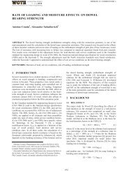
Longitud<strong>in</strong>al <strong>residual</strong> <strong>stress</strong> (MPa)<br />
80<br />
60<br />
40<br />
20<br />
R=5.0m<br />
R=4.0m<br />
R=3.0m<br />
0<br />
10 20 30 40 50<br />
Thickness <strong>of</strong> lam<strong>in</strong>a (mm)<br />
(b) The effect <strong>of</strong> thickness <strong>of</strong> lam<strong>in</strong>a on the longitud<strong>in</strong>al<br />
<strong>residual</strong> <strong>stress</strong><br />
Figure 8: The effect <strong>of</strong> thickness <strong>of</strong> lam<strong>in</strong>a on the<br />
<strong>residual</strong> <strong>stress</strong> (p=0.5MPa, µ=0.1)<br />
5 THE FORMULA FOR<br />
LONGITUDINAL RESIDUAL STRESS<br />
For a lam<strong>in</strong>a <strong>in</strong> a <strong>curved</strong> member under pure bend<strong>in</strong>g,<br />
the maximum bend<strong>in</strong>g <strong>stress</strong> is<br />
Et<br />
σ =<br />
h−t 2( R − )<br />
2<br />
(2)<br />
where, E is the MOE <strong>of</strong> the lam<strong>in</strong>a; R is the radius <strong>of</strong><br />
curvature <strong>of</strong> the neutral axis <strong>of</strong> beam; h is the depth <strong>of</strong><br />
beam; t is the thickness <strong>of</strong> lam<strong>in</strong>a.<br />
In a <strong>curved</strong> Glulam beam, the action <strong>of</strong> gluel<strong>in</strong>e, the<br />
normal <strong>stress</strong> and shear <strong>stress</strong>, <strong>in</strong>duce bend<strong>in</strong>g <strong>of</strong> the<br />
lam<strong>in</strong>a, which is different from pure bend<strong>in</strong>g. The<br />
bend<strong>in</strong>g <strong>stress</strong> can be expressed by Eq. (3) by<br />
<strong>in</strong>troduc<strong>in</strong>g an adjustment factor K .<br />
Et<br />
σ max = K<br />
h−t 2( R − )<br />
2<br />
(3)<br />
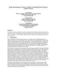
Through the parametric study, the adjustment factor is<br />
obta<strong>in</strong>ed as K =0.76, by regression <strong>of</strong> the maximum<br />
<strong>residual</strong> longitud<strong>in</strong>al <strong>stress</strong> with different radii <strong>of</strong><br />
curvature and thicknesses <strong>of</strong> lam<strong>in</strong>a. For different<br />
thicknesses <strong>of</strong> lam<strong>in</strong>a commonly used <strong>in</strong> <strong>curved</strong> Glulam<br />
and different radii <strong>of</strong> curvature, the longitud<strong>in</strong>al <strong>residual</strong><br />
<strong>stress</strong> from the FE modell<strong>in</strong>g and Eq. (3) are given <strong>in</strong><br />
Figure 9, which shows good correlation <strong>of</strong> the Equation<br />
and the numerical method. The longitud<strong>in</strong>al <strong>residual</strong><br />
<strong>stress</strong> can thus be evaluated by Eq. (3).<br />
Longitud<strong>in</strong>al <strong>residual</strong> <strong>stress</strong> (MPa)<br />
50<br />
40<br />
30<br />
20<br />
(R=5.0m) FE results Eq.(3) results<br />
(R=4.0m) FE results Eq.(3) results<br />
(R=3.0m) FE results Eq.(3) results<br />
10<br />
10 15 20 25 30 35<br />
Thickness <strong>of</strong> lam<strong>in</strong>a (mm)<br />
Figure 9: The longitud<strong>in</strong>al <strong>residual</strong> <strong>stress</strong> regressed by<br />
Eq. (3)<br />
6 CONCLUSIONS<br />
A two-dimensional FE model was developed to simulate<br />
the <strong>residual</strong> <strong>stress</strong> and rebound<strong>in</strong>g deformation <strong>of</strong> <strong>curved</strong><br />
Glulam <strong>beams</strong> dur<strong>in</strong>g manufacture. The <strong>residual</strong> <strong>stress</strong><br />
perpendicular to gra<strong>in</strong> is generally compressive except<br />
for some tension <strong>in</strong> the lam<strong>in</strong>as around the end <strong>of</strong> <strong>curved</strong><br />
<strong>beams</strong>. Quite significant longitud<strong>in</strong>al <strong>residual</strong> <strong>stress</strong><br />
exists <strong>in</strong> the beam, and the longitud<strong>in</strong>al <strong>residual</strong> <strong>stress</strong> <strong>in</strong><br />
the mid-length is larger than that at the end <strong>of</strong> the length.<br />
Each lam<strong>in</strong>a has the similar <strong>stress</strong> distribution due to<br />
bend<strong>in</strong>g. The longitud<strong>in</strong>al <strong>residual</strong> <strong>stress</strong> can be<br />
evaluated by Eq. (3). The most important <strong>in</strong>fluenc<strong>in</strong>g<br />
factors on the longitud<strong>in</strong>al <strong>residual</strong> <strong>stress</strong> are the radius<br />
<strong>of</strong> curvature <strong>of</strong> the neutral axis and the thickness <strong>of</strong><br />
lam<strong>in</strong>a. As for the <strong>residual</strong> <strong>stress</strong> perpendicular to gra<strong>in</strong><br />
and the rebound<strong>in</strong>g deformation, both are closely related<br />
to the radius <strong>of</strong> curvature, pressure, the time <strong>in</strong>terval<br />
between adhesive apply<strong>in</strong>g and pressure apply<strong>in</strong>g and<br />
the thickness <strong>of</strong> lam<strong>in</strong>a. In manufactur<strong>in</strong>g the <strong>curved</strong><br />
<strong>beams</strong>, smaller pressure, smaller thickness <strong>of</strong> lam<strong>in</strong>a and<br />
quicker manufactur<strong>in</strong>g lead to smaller <strong>residual</strong> <strong>stress</strong>es<br />
and rebound<strong>in</strong>g deformation.<br />
Due to the behaviour <strong>of</strong> creep and relaxation <strong>of</strong> wood<br />
and adhesive, the <strong>residual</strong> <strong>stress</strong> from manufactur<strong>in</strong>g will<br />
decrease. This is worth <strong>in</strong>vestigat<strong>in</strong>g <strong>in</strong> future study.<br />
ACKNOWLEDGEMENTS<br />
The writers acknowledge with gratitude the f<strong>in</strong>ancial<br />
support <strong>of</strong> this study from the National Natural Science<br />
Foundation <strong>of</strong> Ch<strong>in</strong>a designated 50878067.<br />
REFERENCES<br />
[1] M. Gong, L. Li, Y. H. Chui, K. Li and N. Yuan.:<br />
Modell<strong>in</strong>g <strong>of</strong> recovery <strong>of</strong> <strong>residual</strong> <strong>stress</strong> <strong>in</strong> densified<br />
wood. In 10th World Conference on Timber<br />
Eng<strong>in</strong>eer<strong>in</strong>g, 2008.<br />
[2] R. A. Shenoi and W. Wang. Through-thickness<br />
<strong>stress</strong>es <strong>in</strong> <strong>curved</strong> composite lam<strong>in</strong>ates and sandwich<br />
<strong>beams</strong>. Composites Science and Technology,<br />
61:1501-1512, 2001.<br />
[3] L. De Lorenzis, J. G. Teng and L. Zhang. Interfacial<br />
<strong>stress</strong>es <strong>in</strong> <strong>curved</strong> members bonded with a th<strong>in</strong> plate.