3D scanner - Wikipedia, the free encyclopedia.pdf - Ex-ch.com
3D scanner - Wikipedia, the free encyclopedia.pdf - Ex-ch.com
3D scanner - Wikipedia, the free encyclopedia.pdf - Ex-ch.com

You also want an ePaper? Increase the reach of your titles
YUMPU automatically turns print PDFs into web optimized ePapers that Google loves.
<strong>3D</strong> <strong>scanner</strong> 1<br />
<strong>3D</strong> <strong>scanner</strong><br />
A <strong>3D</strong> <strong>scanner</strong> is a device that analyzes a real-world object or environment to collect data on its shape and possibly<br />
its appearance (i.e. color). The collected data can <strong>the</strong>n be used to construct digital, three dimensional models useful<br />
for a wide variety of applications. These devices are used extensively by <strong>the</strong> entertainment industry in <strong>the</strong> production<br />
of movies and video games. O<strong>the</strong>r <strong>com</strong>mon applications of this te<strong>ch</strong>nology include industrial design, orthotics and<br />
pros<strong>the</strong>tics, reverse engineering and prototyping, quality control/inspection and documentation of cultural artifacts.<br />
Many different te<strong>ch</strong>nologies can be used to build <strong>the</strong>se <strong>3D</strong> scanning devices; ea<strong>ch</strong> te<strong>ch</strong>nology <strong>com</strong>es with its own<br />
limitations, advantages and costs. It should be remembered that many limitations in <strong>the</strong> kind of objects that can be<br />
digitized are still present: for example optical te<strong>ch</strong>nologies encounter many difficulties with shiny, mirroring or<br />
transparent objects.<br />
There are however methods for scanning shiny objects, su<strong>ch</strong> as covering <strong>the</strong>m with a thin layer of white powder that<br />
will help more light photons to reflect back to <strong>the</strong> <strong>scanner</strong>. Laser <strong>scanner</strong>s can send trillions of light photons toward<br />
an object and only receive a small percentage of those photons back via <strong>the</strong> optics that <strong>the</strong>y use. The reflectivity of<br />
an object is based upon <strong>the</strong> object's color or terrestrial albedo. A white surface will reflect lots of light and a black<br />
surface will reflect only a small amount of light. Transparent objects su<strong>ch</strong> as glass will only refract <strong>the</strong> light and give<br />
false three dimensional information.<br />
Functionality<br />
The purpose of a <strong>3D</strong> <strong>scanner</strong> is usually to create a point cloud of geometric samples on <strong>the</strong> surface of <strong>the</strong> subject.<br />
These points can <strong>the</strong>n be used to extrapolate <strong>the</strong> shape of <strong>the</strong> subject (a process called reconstruction). If color<br />
information is collected at ea<strong>ch</strong> point, <strong>the</strong>n <strong>the</strong> colors on <strong>the</strong> surface of <strong>the</strong> subject can also be determined.<br />
<strong>3D</strong> <strong>scanner</strong>s are very analogous to cameras. Like cameras, <strong>the</strong>y have a cone-like field of view, and like cameras, <strong>the</strong>y<br />
can only collect information about surfaces that are not obscured. While a camera collects color information about<br />
surfaces within its field of view, <strong>3D</strong> <strong>scanner</strong>s collect distance information about surfaces within its field of view. The<br />
“picture” produced by a <strong>3D</strong> <strong>scanner</strong> describes <strong>the</strong> distance to a surface at ea<strong>ch</strong> point in <strong>the</strong> picture. If a spherical<br />
coordinate system is defined in whi<strong>ch</strong> <strong>the</strong> <strong>scanner</strong> is <strong>the</strong> origin and <strong>the</strong> vector out from <strong>the</strong> front of <strong>the</strong> <strong>scanner</strong> is φ=0<br />
and θ=0, <strong>the</strong>n ea<strong>ch</strong> point in <strong>the</strong> picture is associated with a φ and θ. Toge<strong>the</strong>r with distance, whi<strong>ch</strong> corresponds to<br />
<strong>the</strong> r <strong>com</strong>ponent, <strong>the</strong>se spherical coordinates fully describe <strong>the</strong> three dimensional position of ea<strong>ch</strong> point in <strong>the</strong><br />
picture, in a local coordinate system relative to <strong>the</strong> <strong>scanner</strong>.<br />
For most situations, a single scan will not produce a <strong>com</strong>plete model of <strong>the</strong> subject. Multiple scans, even hundreds,<br />
from many different directions are usually required to obtain information about all sides of <strong>the</strong> subject. These scans<br />
have to be brought in a <strong>com</strong>mon reference system, a process that is usually called alignment or registration, and <strong>the</strong>n<br />
merged to create a <strong>com</strong>plete model. This whole process, going from <strong>the</strong> single range map to <strong>the</strong> whole model, is<br />
usually known as <strong>the</strong> <strong>3D</strong> scanning pipeline. [1]
<strong>3D</strong> <strong>scanner</strong> 2<br />
Te<strong>ch</strong>nology<br />
There are a variety of te<strong>ch</strong>nologies for digitally acquiring <strong>the</strong> shape of a <strong>3D</strong> object. A well established<br />
classification [2] divides <strong>the</strong>m into two types: contact and non-contact <strong>3D</strong> <strong>scanner</strong>s. Non-contact <strong>3D</strong> <strong>scanner</strong>s can be<br />
fur<strong>the</strong>r divided into two main categories, active <strong>scanner</strong>s and passive <strong>scanner</strong>s. There are a variety of te<strong>ch</strong>nologies<br />
that fall under ea<strong>ch</strong> of <strong>the</strong>se categories.<br />
Contact<br />
Contact <strong>3D</strong> <strong>scanner</strong>s probe <strong>the</strong> subject through physical tou<strong>ch</strong>. A CMM (coordinate measuring ma<strong>ch</strong>ine) is an<br />
example of a contact <strong>3D</strong> <strong>scanner</strong>. It is used mostly in manufacturing and can be very precise. The disadvantage of<br />
CMMs though, is that it requires contact with <strong>the</strong> object being scanned. Thus, <strong>the</strong> act of scanning <strong>the</strong> object might<br />
modify or damage it. This fact is very significant when scanning delicate or valuable objects su<strong>ch</strong> as historical<br />
artifacts. The o<strong>the</strong>r disadvantage of CMMs is that <strong>the</strong>y are relatively slow <strong>com</strong>pared to <strong>the</strong> o<strong>the</strong>r scanning methods.<br />
Physically moving <strong>the</strong> arm that <strong>the</strong> probe is mounted on can be very slow and <strong>the</strong> fastest CMMs can only operate on<br />
a few hundred hertz. In contrast, an optical system like a laser <strong>scanner</strong> can operate from 10 to 500 kHz.<br />
O<strong>the</strong>r examples are <strong>the</strong> hand driven tou<strong>ch</strong> probes used to digitize clay models in <strong>com</strong>puter animation industry.<br />
Non-contact active<br />
Active <strong>scanner</strong>s emit some kind of radiation or light and detect its reflection in order to probe an object or<br />
environment. Possible types of emissions used include light, ultrasound or x-ray.<br />
Time-of-flight<br />
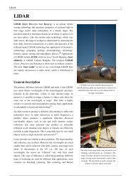
This lidar <strong>scanner</strong> may be used to scan buildings,<br />
rock formations, etc., to produce a <strong>3D</strong> model. The<br />
lidar can aim its laser beam in a wide range: its<br />
head rotates horizontally, a mirror flips vertically.<br />
The laser beam is used to measure <strong>the</strong> distance to<br />
<strong>the</strong> first object on its path.<br />
The time-of-flight <strong>3D</strong> laser <strong>scanner</strong> is an active <strong>scanner</strong> that uses laser light to probe <strong>the</strong> subject. At <strong>the</strong> heart of this<br />
type of <strong>scanner</strong> is a time-of-flight laser rangefinder. The laser rangefinder finds <strong>the</strong> distance of a surface by timing<br />
<strong>the</strong> round-trip time of a pulse of light. A laser is used to emit a pulse of light and <strong>the</strong> amount of time before <strong>the</strong><br />
reflected light is seen by a detector is timed. Since <strong>the</strong> speed of light is a known, <strong>the</strong> round-trip time determines
<strong>3D</strong> <strong>scanner</strong> 3<br />
<strong>the</strong> travel distance of <strong>the</strong> light, whi<strong>ch</strong> is twice <strong>the</strong> distance between <strong>the</strong> <strong>scanner</strong> and <strong>the</strong> surface. If is <strong>the</strong> round-trip<br />
time, <strong>the</strong>n distance is equal to . The accuracy of a time-of-flight <strong>3D</strong> laser <strong>scanner</strong> depends on how precisely we can<br />
measure <strong>the</strong> time: 3.3 picoseconds (approx.) is <strong>the</strong> time taken for light to travel 1 millimetre.<br />
The laser rangefinder only detects <strong>the</strong> distance of one point in its direction of view. Thus, <strong>the</strong> <strong>scanner</strong> scans its entire<br />
field of view one point at a time by <strong>ch</strong>anging <strong>the</strong> range finder’s direction of view to scan different points. The view<br />
direction of <strong>the</strong> laser rangefinder can be <strong>ch</strong>anged ei<strong>the</strong>r by rotating <strong>the</strong> range finder itself, or by using a system of<br />
rotating mirrors. The latter method is <strong>com</strong>monly used because mirrors are mu<strong>ch</strong> lighter and can thus be rotated mu<strong>ch</strong><br />
faster and with greater accuracy. Typical time-of-flight <strong>3D</strong> laser <strong>scanner</strong>s can measure <strong>the</strong> distance of<br />
10,000~100,000 points every second.<br />
Time-of-flight devices are also available in a 2D configuration. This is referred to as a Time-of-flight camera.<br />
Triangulation<br />
The triangulation <strong>3D</strong> laser <strong>scanner</strong> is also an active <strong>scanner</strong> that uses<br />
laser light to probe <strong>the</strong> environment. With respect to time-of-flight <strong>3D</strong><br />
laser <strong>scanner</strong> <strong>the</strong> triangulation laser shines a laser on <strong>the</strong> subject and<br />
exploits a camera to look for <strong>the</strong> location of <strong>the</strong> laser dot. Depending<br />
on how far away <strong>the</strong> laser strikes a surface, <strong>the</strong> laser dot appears at<br />
different places in <strong>the</strong> camera’s field of view. This te<strong>ch</strong>nique is called<br />
triangulation because <strong>the</strong> laser dot, <strong>the</strong> camera and <strong>the</strong> laser emitter<br />
form a triangle. The length of one side of <strong>the</strong> triangle, <strong>the</strong> distance<br />
between <strong>the</strong> camera and <strong>the</strong> laser emitter is known. The angle of <strong>the</strong><br />
laser emitter corner is also known. The angle of <strong>the</strong> camera corner can<br />
be determined by looking at <strong>the</strong> location of <strong>the</strong> laser dot in <strong>the</strong> camera’s<br />
field of view. These three pieces of information fully determine <strong>the</strong><br />
shape and size of <strong>the</strong> triangle and gives <strong>the</strong> location of <strong>the</strong> laser dot<br />
corner of <strong>the</strong> triangle. In most cases a laser stripe, instead of a single<br />
laser dot, is swept across <strong>the</strong> object to speed up <strong>the</strong> acquisition process.<br />
The National Resear<strong>ch</strong> Council of Canada was among <strong>the</strong> first<br />
institutes to develop <strong>the</strong> triangulation based laser scanning te<strong>ch</strong>nology<br />
in 1978. [3]<br />
Notes on time-of-flight and triangulation <strong>scanner</strong>s<br />
Time-of-flight and triangulation range finders ea<strong>ch</strong> have strengths and<br />
weaknesses that make <strong>the</strong>m suitable for different situations. The<br />
advantage of time-of-flight range finders is that <strong>the</strong>y are capable of<br />
operating over very long distances, on <strong>the</strong> order of kilometers. These<br />
<strong>scanner</strong>s are thus suitable for scanning large structures like buildings or<br />
geographic features. The disadvantage of time-of-flight range finders is<br />
<strong>the</strong>ir accuracy. Due to <strong>the</strong> high speed of light, timing <strong>the</strong> round-trip<br />
Principle of a laser triangulation sensor. Two<br />
object positions are shown.<br />
point cloud generation using triangulation with a<br />
laser stripe.<br />
time is difficult and <strong>the</strong> accuracy of <strong>the</strong> distance measurement is relatively low, on <strong>the</strong> order of millimeters.<br />
Triangulation range finders are exactly <strong>the</strong> opposite. They have a limited range of some meters, but <strong>the</strong>ir accuracy is<br />
relatively high. The accuracy of triangulation range finders is on <strong>the</strong> order of tens of micrometers.<br />
Time of flight <strong>scanner</strong>s accuracy can be lost when <strong>the</strong> laser hits <strong>the</strong> edge of an object because <strong>the</strong> information that is<br />
sent back to <strong>the</strong> <strong>scanner</strong> is from two different locations for one laser pulse. The coordinate relative to <strong>the</strong> <strong>scanner</strong>s<br />
position for a point that has hit <strong>the</strong> edge of an object will be calculated based on an average and <strong>the</strong>refore will put <strong>the</strong><br />
point in <strong>the</strong> wrong place. When using a high resolution scan on an object <strong>the</strong> <strong>ch</strong>ances of <strong>the</strong> beam hitting an edge are
<strong>3D</strong> <strong>scanner</strong> 4<br />
increased and <strong>the</strong> resulting data will show noise just behind <strong>the</strong> edges of <strong>the</strong> object. Scanners with a smaller beam<br />
width will help to solve this problem but will be limited by range as <strong>the</strong> beam width will increase over distance.<br />
Software can also help by determining that <strong>the</strong> first object to be hit by <strong>the</strong> laser beam should cancel out <strong>the</strong> second.<br />
At a rate of 10,000 sample points per second, low resolution scans can take less than a second, but high resolution<br />
scans, requiring millions of samples, can take minutes for some time-of-flight <strong>scanner</strong>s. The problem this creates is<br />
distortion from motion. Since ea<strong>ch</strong> point is sampled at a different time, any motion in <strong>the</strong> subject or <strong>the</strong> <strong>scanner</strong> will<br />
distort <strong>the</strong> collected data. Thus, it is usually necessary to mount both <strong>the</strong> subject and <strong>the</strong> <strong>scanner</strong> on stable platforms<br />
and minimize vibration. Using <strong>the</strong>se <strong>scanner</strong>s to scan objects in motion is very difficult.<br />
Recently, <strong>the</strong>re has been resear<strong>ch</strong> on <strong>com</strong>pensating for distortion from small amounts of vibration. [4]<br />
When scanning in one position for any length of time slight movement can occur in <strong>the</strong> <strong>scanner</strong> position due to<br />
<strong>ch</strong>anges in temperature. If <strong>the</strong> <strong>scanner</strong> is set on a tripod and <strong>the</strong>re is strong sunlight on one side of <strong>the</strong> <strong>scanner</strong> <strong>the</strong>n<br />
that side of <strong>the</strong> tripod will expand and slowly distort <strong>the</strong> scan data from one side to ano<strong>the</strong>r. Some laser <strong>scanner</strong>s<br />
have level <strong>com</strong>pensators built into <strong>the</strong>m to counteract any movement of <strong>the</strong> <strong>scanner</strong> during <strong>the</strong> scan process.<br />
Conoscopic holography<br />
In a Conoscopic system, a laser beam is projected onto <strong>the</strong> surface and <strong>the</strong>n <strong>the</strong> immediate reflection along <strong>the</strong> same<br />
ray-path are put through a conoscopic crystal and projected onto a CCD. The result is a diffraction pattern, that can<br />
be frequency analyzed to determine <strong>the</strong> distance to <strong>the</strong> measured surface. The main advantage with Conoscopic<br />
Holography is that only a single ray-path is needed for measuring, thus giving an opportunity to measure for instance<br />
<strong>the</strong> depth of a finely drilled hole.<br />
Hand-held laser<br />
Hand-held laser <strong>scanner</strong>s create a <strong>3D</strong> image through <strong>the</strong> triangulation me<strong>ch</strong>anism described above: a laser dot or line<br />
is projected onto an object from a hand-held device and a sensor (typically a <strong>ch</strong>arge-coupled device or position<br />
sensitive device) measures <strong>the</strong> distance to <strong>the</strong> surface. Data is collected in relation to an internal coordinate system<br />
and <strong>the</strong>refore to collect data where <strong>the</strong> <strong>scanner</strong> is in motion <strong>the</strong> position of <strong>the</strong> <strong>scanner</strong> must be determined. The<br />
position can be determined by <strong>the</strong> <strong>scanner</strong> using reference features on <strong>the</strong> surface being scanned (typically adhesive<br />
reflective tabs) or by using an external tracking method. <strong>Ex</strong>ternal tracking often takes <strong>the</strong> form of a laser tracker (to<br />
provide <strong>the</strong> sensor position) with integrated camera (to determine <strong>the</strong> orientation of <strong>the</strong> <strong>scanner</strong>) or a<br />
photogrammetric solution using 3 or more cameras providing <strong>the</strong> <strong>com</strong>plete Six degrees of <strong>free</strong>dom of <strong>the</strong> <strong>scanner</strong>.<br />
Both te<strong>ch</strong>niques tend to use infrared Light-emitting diodes atta<strong>ch</strong>ed to <strong>the</strong> <strong>scanner</strong> whi<strong>ch</strong> are seen by <strong>the</strong> camera(s)<br />
through filters providing resilience to ambient lighting.<br />
Data is collected by a <strong>com</strong>puter and recorded as data points within Three-dimensional space, with processing this<br />
can be converted into a triangulated mesh and <strong>the</strong>n a Computer-aided design model, often as Nonuniform rational<br />
B-spline surfaces. Hand-held laser <strong>scanner</strong>s can <strong>com</strong>bine this data with passive, visible-light sensors - whi<strong>ch</strong> capture<br />
surface textures and colors - to build (or "reverse engineer") a full <strong>3D</strong> model.<br />
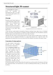
Structured light<br />
Structured-light <strong>3D</strong> <strong>scanner</strong>s project a pattern of light on <strong>the</strong> subject and look at <strong>the</strong> deformation of <strong>the</strong> pattern on <strong>the</strong><br />
subject. The pattern may be one dimensional or two dimensional. An example of a one dimensional pattern is a line.<br />
The line is projected onto <strong>the</strong> subject using ei<strong>the</strong>r an LCD projector or a sweeping laser. A camera, offset slightly<br />
from <strong>the</strong> pattern projector, looks at <strong>the</strong> shape of <strong>the</strong> line and uses a te<strong>ch</strong>nique similar to triangulation to calculate <strong>the</strong><br />
distance of every point on <strong>the</strong> line. In <strong>the</strong> case of a single-line pattern, <strong>the</strong> line is swept across <strong>the</strong> field of view to<br />
ga<strong>the</strong>r distance information one strip at a time.<br />
An example of a two-dimensional pattern is a grid or a line stripe pattern. A camera is used to look at <strong>the</strong><br />
deformation of <strong>the</strong> pattern, and an algorithm is used to calculate <strong>the</strong> distance at ea<strong>ch</strong> point in <strong>the</strong> pattern. Consider an
<strong>3D</strong> <strong>scanner</strong> 5<br />
array of parallel vertical laser stripes sweeping horizontally across a target. In <strong>the</strong> simplest case, one could analyze an<br />
image and assume that <strong>the</strong> left-to-right sequence of stripes reflects <strong>the</strong> sequence of <strong>the</strong> lasers in <strong>the</strong> array, so that <strong>the</strong><br />
leftmost image stripe is <strong>the</strong> first laser, <strong>the</strong> next one is <strong>the</strong> second laser, and so on. In non-trivial targets having holes,<br />
occlusions, and rapid depth <strong>ch</strong>anges, however, this sequencing breaks down as stripes are often hidden and may even<br />
appear to <strong>ch</strong>ange order, resulting in laser stripe ambiguity. This problem can be solved using algorithms for<br />
multistripe laser triangulation. Structured-light scanning is still a very active area of resear<strong>ch</strong> with many resear<strong>ch</strong><br />
papers published ea<strong>ch</strong> year.<br />
The advantage of structured-light <strong>3D</strong> <strong>scanner</strong>s is speed. Instead of scanning one point at a time, structured light<br />
<strong>scanner</strong>s scan multiple points or <strong>the</strong> entire field of view at once. This reduces or eliminates <strong>the</strong> problem of distortion<br />
from motion. Some existing systems are capable of scanning moving objects in real-time.<br />
A real-time <strong>scanner</strong> a using digital fringe projection and phase-shifting te<strong>ch</strong>nique (a various structured light method)<br />
was developed, to capture, reconstruct, and render high-density details of dynamically deformable objects (su<strong>ch</strong> as<br />
facial expressions) at 40 frames per second. [5] Recently, ano<strong>the</strong>r <strong>scanner</strong> is developed. Different patterns can be<br />
applied to this system. The frame rate for capturing and data processing a<strong>ch</strong>ieves 120 frames per second. It can also<br />
scan isolated surfaces, for example two moving hands. [6]<br />
Modulated light<br />
Modulated light <strong>3D</strong> <strong>scanner</strong>s shine a continually <strong>ch</strong>anging light at <strong>the</strong> subject. Usually <strong>the</strong> light source simply cycles<br />
its amplitude in a sinusoidal pattern. A camera detects <strong>the</strong> reflected light and <strong>the</strong> amount <strong>the</strong> pattern is shifted by<br />
determines <strong>the</strong> distance <strong>the</strong> light traveled. Modulated light also allows <strong>the</strong> <strong>scanner</strong> to ignore light from sources o<strong>the</strong>r<br />
than a laser, so <strong>the</strong>re is no interference.<br />
Volumetric Te<strong>ch</strong>niques<br />
Computed tomography (CT) is a medical imaging method whi<strong>ch</strong> generates a three-dimensional image of <strong>the</strong> inside<br />
of an object from a large series of two-dimensional X-ray images, similarly Magnetic resonance imaging is ano<strong>the</strong>r a<br />
medical imaging te<strong>ch</strong>nique that provides mu<strong>ch</strong> greater contrast between <strong>the</strong> different soft tissues of <strong>the</strong> body than<br />
<strong>com</strong>puted tomography (CT) does, making it especially useful in neurological (brain), musculoskeletal,<br />
cardiovascular, and oncological (cancer) imaging. These te<strong>ch</strong>niques produce a discrete <strong>3D</strong> volumetric representation<br />
that can be directly visualized, manipulated or converted to traditional <strong>3D</strong> surface by mean of isosurface extraction<br />
algorithms . Although most <strong>com</strong>mon in medicine, Computed tomography, Microtomography and MRI are also used<br />
in o<strong>the</strong>r fields for acquiring a digital representation of an object and its interior, su<strong>ch</strong> as nondestructive materials<br />
testing, reverse engineering, or <strong>the</strong> study biological and paleontological specimens.<br />
Non-contact passive<br />
Passive <strong>scanner</strong>s do not emit any kind of radiation <strong>the</strong>mselves, but instead rely on detecting reflected ambient<br />
radiation. Most <strong>scanner</strong>s of this type detect visible light because it is a readily available ambient radiation. O<strong>the</strong>r<br />
types of radiation, su<strong>ch</strong> as infrared could also be used. Passive methods can be very <strong>ch</strong>eap, because in most cases<br />
<strong>the</strong>y do not need particular hardware but simple digital cameras.<br />
• Stereoscopic systems usually employ two video cameras, slightly apart, looking at <strong>the</strong> same scene. By analyzing<br />
<strong>the</strong> slight differences between <strong>the</strong> images seen by ea<strong>ch</strong> camera, it is possible to determine <strong>the</strong> distance at ea<strong>ch</strong><br />
point in <strong>the</strong> images. This method is based on <strong>the</strong> same principles driving human stereoscopic vision[7].<br />
• Photometric systems usually use a single camera, but take multiple images under varying lighting conditions.<br />
These te<strong>ch</strong>niques attempt to invert <strong>the</strong> image formation model in order to recover <strong>the</strong> surface orientation at ea<strong>ch</strong><br />
pixel.<br />
• Silhouette te<strong>ch</strong>niques use outlines created from a sequence of photographs around a three-dimensional object<br />
against a well contrasted background. These silhouettes are extruded and intersected to form <strong>the</strong> visual hull
<strong>3D</strong> <strong>scanner</strong> 6<br />
approximation of <strong>the</strong> object. With <strong>the</strong>se approa<strong>ch</strong>es some concavities of an object (like <strong>the</strong> interior of a bowl)<br />
cannot be detected.<br />
User assisted (image-based modeling)<br />
There are o<strong>the</strong>r methods that, based on <strong>the</strong> user assisted detection and identification of some features and shapes on a<br />
set of different pictures of an object are able to build an approximation of <strong>the</strong> object itself. This kind of te<strong>ch</strong>niques<br />
are useful to build fast approximation of simple shaped objects like buildings. Various <strong>com</strong>mercial packages are<br />
available like iModeller, D-Sculptor or Autodesk ImageModeler.<br />
This sort of <strong>3D</strong> scanning is based on <strong>the</strong> principles of photogrammetry. It is also somewhat similar in methodology<br />
to panoramic photography, except that <strong>the</strong> photos are taken of one object on a three-dimensional space in order to<br />
replicate it instead of taking a series of photos from one point in a three-dimensional space in order to replicate <strong>the</strong><br />
surrounding environment.<br />
Reconstruction, or Modeling<br />
From point clouds<br />
The point clouds produced by <strong>3D</strong> <strong>scanner</strong>s can be used directly for measurement and visualization in <strong>the</strong> ar<strong>ch</strong>itecture<br />
and construction world.<br />
Most applications, however, use instead polygonal <strong>3D</strong> models, NURBS surface models, or editable feature-based<br />
CAD models (aka Solid models).<br />
Polygon mesh models<br />
In a polygonal representation of a shape, a curved surface is modeled as many small faceted flat surfaces<br />
(think of a sphere modeled as a disco ball). Polygon models—also called Mesh models, are useful for<br />
visualization, for some CAM (i.e., ma<strong>ch</strong>ining), but are generally "heavy" ( i.e., very large data sets), and are<br />
relatively un-editable in this form. Reconstruction to polygonal model involves finding and connecting<br />
adjacent points with straight lines in order to create a continuous surface. Many applications, both <strong>free</strong> and non<br />
<strong>free</strong>, are available for this purpose (eg. MeshLab, kubit PointCloud for AutoCAD, JRC <strong>3D</strong> Reconstructor,<br />
photomodeler, imagemodel, PolyWorks, Rapidform, Geomagic, Imageware, Rhino etc.).<br />
Surface models<br />
The next level of sophistication in modeling involves using a quilt of curved surface pat<strong>ch</strong>es to model our<br />
shape. These might be NURBS, TSplines or o<strong>the</strong>r curved representations of curved topology. Using NURBS,<br />
our sphere is a true ma<strong>the</strong>matical sphere. Some applications offer pat<strong>ch</strong> layout by hand but <strong>the</strong> best in class<br />
offer both automated pat<strong>ch</strong> layout and manual layout. These pat<strong>ch</strong>es have <strong>the</strong> advantage of being lighter and<br />
more manipulable when exported to CAD. Surface models are somewhat editable, but only in a sculptural<br />
sense of pushing and pulling to deform <strong>the</strong> surface. This representation lends itself well to modeling organic<br />
and artistic shapes. Providers of surface modelers include Rapidform, Geomagic, Rhino, Maya, T Splines etc.<br />
Solid CAD models<br />
From an engineering/manufacturing perspective, <strong>the</strong> ultimate representation of a digitized shape is <strong>the</strong><br />
editable, parametric CAD model. After all, CAD is <strong>the</strong> <strong>com</strong>mon "language" of industry to describe, edit and<br />
maintain <strong>the</strong> shape of <strong>the</strong> enterprise's assets. In CAD, our sphere is described by parametric features whi<strong>ch</strong> are<br />
easily edited by <strong>ch</strong>anging a value(e.g., centerpoint and radius).<br />
These CAD models describe not simply <strong>the</strong> envelope or shape of <strong>the</strong> object, but CAD models also embody <strong>the</strong><br />
"design intent" (i.e., critical features and <strong>the</strong>ir relationship to o<strong>the</strong>r features). An example of design intent not evident<br />
in <strong>the</strong> shape alone might be a brake drum's lug bolts, whi<strong>ch</strong> must be concentric with <strong>the</strong> hole in <strong>the</strong> center of <strong>the</strong><br />
drum. This knowledge would drive <strong>the</strong> sequence and method of creating <strong>the</strong> CAD model; a designer with an
<strong>3D</strong> <strong>scanner</strong> 7<br />
awareness of this relationship would not design <strong>the</strong> lug bolts referenced to <strong>the</strong> outside diameter, but instead, to <strong>the</strong><br />
center. A modeler creating a CAD model will want to include both Shape and design intent in <strong>the</strong> <strong>com</strong>plete CAD<br />
model.<br />
Vendors offer different approa<strong>ch</strong>es to getting to <strong>the</strong> parametric CAD model. Some export <strong>the</strong> NURBS surfaces and<br />
leave it to <strong>the</strong> CAD designer to <strong>com</strong>plete <strong>the</strong> model in CAD (e.g., Geomagic, Imageware, Rhino). O<strong>the</strong>rs use <strong>the</strong><br />
scan data to create an editable and verifiable feature based model that is imported into CAD with full feature tree<br />
intact, yielding a <strong>com</strong>plete, native CAD model, capturing both shape and design intent (e.g. Geomagic, Rapidform).<br />
Still o<strong>the</strong>r CAD applications are robust enough to manipulate limited points or polygon models within <strong>the</strong> CAD<br />
environment(e.g., Catia).<br />
From a set of 2D slices<br />
CT, MRI, or Micro-CT <strong>scanner</strong>s do not produce point clouds but a set of 2D slices (ea<strong>ch</strong> termed a "tomogram")<br />
whi<strong>ch</strong> are <strong>the</strong>n 'stacked toge<strong>the</strong>r' to produce a <strong>3D</strong> representation. There are several ways to do this depending on <strong>the</strong><br />
output required:<br />
Volume rendering<br />
Different parts of an object usually have different threshold values or greyscale densities. From this, a<br />
3-dimensional model can be constructed and displayed on screen. Multiple models can be constructed from<br />
various different thresholds, allowing different colors to represent ea<strong>ch</strong> <strong>com</strong>ponent of <strong>the</strong> object. Volume<br />
rendering is usually only used for visualisation of <strong>the</strong> scanned object.<br />
Image segmentation<br />
Where different structures have similar threshold/greyscale values, it can be<strong>com</strong>e impossible to separate <strong>the</strong>m<br />
simply by adjusting volume rendering parameters. The solution is called segmentation, a manual or automatic<br />
procedure that can remove <strong>the</strong> unwanted structures from <strong>the</strong> image. Image segmentation software usually<br />
allows export of <strong>the</strong> segmented structures in CAD or STL format for fur<strong>the</strong>r manipulation.<br />
Image-based meshing<br />
When using <strong>3D</strong> image data for <strong>com</strong>putational analysis (e.g. CFD and FEA), simply segmenting <strong>the</strong> data and<br />
meshing from CAD can be<strong>com</strong>e time consuming, and virtually intractable for <strong>the</strong> <strong>com</strong>plex topologies typical<br />
of image data. The solution is called image-based meshing, an automated process of generating an accurate<br />
and realistic geometrical description of <strong>the</strong> scan data.<br />
Applications<br />
Material processing and production<br />
Laser scanning describes a method where a surface is sampled or scanned using laser te<strong>ch</strong>nology. Several areas of<br />
application exist that mainly differ in <strong>the</strong> power of <strong>the</strong> lasers that are used, and in <strong>the</strong> results of <strong>the</strong> scanning process.<br />
Lasers with low power are used when <strong>the</strong> scanned surface doesn't have to be influenced, e.g. when it has to be<br />
digitized. Confocal or <strong>3D</strong> laser scanning are methods to get information about <strong>the</strong> scanned surface.<br />
Depending on <strong>the</strong> power of <strong>the</strong> laser, its influence on a working piece differs: lower power values are used for laser<br />
engraving, where material is partially removed by <strong>the</strong> laser. With higher powers <strong>the</strong> material be<strong>com</strong>es fluid and laser<br />
welding can be realized, or if <strong>the</strong> power is high enough to remove <strong>the</strong> material <strong>com</strong>pletely, <strong>the</strong>n laser cutting can be<br />
performed.<br />
Also for rapid prototyping a laser scanning procedure is used when for example a prototype is generated by laser<br />
sintering.<br />
The principle that is used for all <strong>the</strong>se applications is <strong>the</strong> same: software that runs on a PC or an embedded system<br />
and that controls <strong>the</strong> <strong>com</strong>plete process is connected with a <strong>scanner</strong> card. That card converts <strong>the</strong> received vector data
<strong>3D</strong> <strong>scanner</strong> 8<br />
to movement information whi<strong>ch</strong> is sent to <strong>the</strong> scanhead. This scanhead consists of two mirrors that are able to deflect<br />
<strong>the</strong> laser beam in one level (X- and Y-coordinate). The third dimension is - if necessary - realized by a specific optic<br />
that is able to move <strong>the</strong> laser's focal point in <strong>the</strong> depth-direction (Z-axis).<br />
The third dimension is needed for some special applications like <strong>the</strong> rapid prototyping where an object is built up<br />
layer by layer or for in-glass-marking where <strong>the</strong> laser has to influence <strong>the</strong> material at specific positions within it. For<br />
<strong>the</strong>se cases it is important that <strong>the</strong> laser has as small a focal point as possible.<br />
For enhanced laser scanning applications and/or high material throughput during production, scanning systems with<br />
more than one scanhead are used. Here <strong>the</strong> software has to control what is done exactly within su<strong>ch</strong> a multihead<br />
application: it is possible that all available heads have to mark <strong>the</strong> same to finish processing faster or that <strong>the</strong> heads<br />
mark one single job in parallel where every scanhead performs a part of <strong>the</strong> job in case of large working areas.<br />
Structured light projection systems are also used for solar cell flatness metrology enabling stress calculation with<br />
throughput in excess of 2000 wafers per hour. [8]<br />
Construction industry and civil engineering<br />
[9] [10]<br />
• Robotic Control: e.g., a laser <strong>scanner</strong> may function as <strong>the</strong> "eye" of a robot.<br />
• As-built drawings of Bridges, Industrial Plants, and Monuments<br />
• Documentation of historical sites<br />
• Site modeling and lay outing<br />
• Quality control<br />
• Quantity Surveys<br />
• Freeway Redesign<br />
• Establishing a ben<strong>ch</strong> mark of pre-existing shape/state in order to detect structural <strong>ch</strong>anges resulting from exposure<br />
to extreme loadings su<strong>ch</strong> as earthquake, vessel/truck impact or fire.<br />
• Create GIS (Geographic information system) maps and Geomatics.<br />
Benefits of <strong>3D</strong> scanning<br />
<strong>3D</strong> model scanning could benefit <strong>the</strong> design process if:<br />
• Increase effectiveness working with <strong>com</strong>plex parts and shapes.<br />
• Help with design of products to ac<strong>com</strong>modate someone else’s part.<br />
• If CAD models are outdated, a <strong>3D</strong> scan will provide an updated version<br />
• Replacement of missing or older parts<br />
Entertainment<br />
<strong>3D</strong> <strong>scanner</strong>s are used by <strong>the</strong> entertainment industry to create digital <strong>3D</strong> models for both movies and video games. In<br />
cases where a real-world equivalent of a model exists, it is mu<strong>ch</strong> faster to scan <strong>the</strong> real-world object than to manually<br />
create a model using <strong>3D</strong> modeling software. Frequently, artists sculpt physical models of what <strong>the</strong>y want and scan<br />
<strong>the</strong>m into digital form ra<strong>the</strong>r than directly creating digital models on a <strong>com</strong>puter.<br />
Reverse engineering<br />
Reverse engineering of a me<strong>ch</strong>anical <strong>com</strong>ponent requires a precise digital model of <strong>the</strong> objects to be reproduced.<br />
Ra<strong>the</strong>r than a set of points a precise digital model can be represented by a polygon mesh, a set of flat or curved<br />
NURBS surfaces, or ideally for me<strong>ch</strong>anical <strong>com</strong>ponents, a CAD solid model. A <strong>3D</strong> <strong>scanner</strong> can be used to digitize<br />
<strong>free</strong>-form or gradually <strong>ch</strong>anging shaped <strong>com</strong>ponents as well as prismatic geometries whereas a coordinate measuring<br />
ma<strong>ch</strong>ine is usually used only to determine simple dimensions of a highly prismatic model. These data points are <strong>the</strong>n<br />
processed to create a usable digital model, usually using specialized reverse engineering software (see Modeling;
<strong>3D</strong> <strong>scanner</strong> 9<br />
Solid Models, above).<br />
Cultural Heritage<br />
There have been many resear<strong>ch</strong> projects undertaken via <strong>the</strong> scanning of<br />
historical sites and artifacts both for documentation and analysis<br />
purposes.<br />
The <strong>com</strong>bined use of <strong>3D</strong> scanning and <strong>3D</strong> printing te<strong>ch</strong>nologies allows<br />
<strong>the</strong> replication of real objects without <strong>the</strong> use of traditional plaster<br />
casting te<strong>ch</strong>niques, that in many cases can be too invasive for being<br />
performed on precious or delicate cultural heritage artifacts [11] . In <strong>the</strong><br />
side figure <strong>the</strong> gargoyle model on <strong>the</strong> left was digitally acquired by<br />
using a <strong>3D</strong> <strong>scanner</strong> and <strong>the</strong> produced <strong>3D</strong> data was processed using<br />
MeshLab. The resulting digital <strong>3D</strong> model, shown in <strong>the</strong> screen of <strong>the</strong><br />
laptop, was used by a rapid prototyping ma<strong>ch</strong>ine to create a real resin<br />
replica of original object.<br />
Mi<strong>ch</strong>elangelo<br />
An example of real object replication by means of<br />
<strong>3D</strong> scanning and <strong>3D</strong> printing<br />
In 1999, two different resear<strong>ch</strong> groups started scanning Mi<strong>ch</strong>elangelo's statues. Stanford University with a group led<br />
by Marc Levoy [12] used a custom laser triangulation <strong>scanner</strong> built by Cyberware to scan Mi<strong>ch</strong>elangelo’s statues in<br />
Florence, notably <strong>the</strong> David, <strong>the</strong> Prigioni and <strong>the</strong> four statues in The Medici Chapel. The scans produced a data point<br />
density of one sample per 0.25 mm, detailed enough to see Mi<strong>ch</strong>elangelo’s <strong>ch</strong>isel marks. These detailed scans<br />
produced a huge amount of data (up to 32 gigabytes) and processing <strong>the</strong> data from his scans took 5 months.<br />
Approximately in <strong>the</strong> same period a resear<strong>ch</strong> group from IBM, led by H. Rushmeier and F. Bernardini scanned <strong>the</strong><br />
Pietà of Florence acquiring both geometric and color details. The digital model, result of <strong>the</strong> Stanford scanning<br />
campaign, was thoroughly used in <strong>the</strong> 2004 subsequent restoration of <strong>the</strong> statue [13] .<br />
Monticello<br />
In 2002, David Luebke, et al. scanned Thomas Jefferson’s Monticello. [14] A <strong>com</strong>mercial time of flight laser <strong>scanner</strong>,<br />
<strong>the</strong> DeltaSphere 3000, was used. The <strong>scanner</strong> data was later <strong>com</strong>bined with color data from digital photographs to<br />
create <strong>the</strong> Virtual Monticello, and <strong>the</strong> Jefferson’s Cabinet exhibits in <strong>the</strong> New Orleans Museum of Art in 2003. The<br />
Virtual Monticello exhibit simulated a window looking into Jefferson’s Library. The exhibit consisted of a rear<br />
projection display on a wall and a pair of stereo glasses for <strong>the</strong> viewer. The glasses, <strong>com</strong>bined with polarized<br />
projectors, provided a <strong>3D</strong> effect. Position tracking hardware on <strong>the</strong> glasses allowed <strong>the</strong> display to adapt as <strong>the</strong> viewer<br />
moves around, creating <strong>the</strong> illusion that <strong>the</strong> display is actually a hole in <strong>the</strong> wall looking into Jefferson’s Library. The<br />
Jefferson’s Cabinet exhibit was a barrier stereogram (essentially a non-active hologram that appears different from<br />
different angles) of Jefferson’s Cabinet
<strong>3D</strong> <strong>scanner</strong> 10<br />
Cuneiform tablets<br />
In 2003, Subodh Kumar, et al. undertook <strong>the</strong> <strong>3D</strong> scanning of ancient cuneiform tablets. [15] Again, a laser<br />
triangulation <strong>scanner</strong> was used. The tablets were scanned on a regular grid pattern at a resolution of 0.025 mm.<br />
Kasubi Tombs<br />
A 2009 CyArk <strong>3D</strong> scanning project at Uganda's historic Kasubi<br />
Tombs, a UNESCO World Heritage Site, using a Leica HDS 4500,<br />
produced detailed ar<strong>ch</strong>itectural models of Muzibu Azaala Mpanga, <strong>the</strong><br />
main building at <strong>the</strong> <strong>com</strong>plex and tomb of <strong>the</strong> Kabakas (Kings) of<br />
Uganda. A fire on Mar<strong>ch</strong> 16, 2010, burned down mu<strong>ch</strong> of <strong>the</strong> Muzibu<br />
Azaala Mpanga structure, and reconstruction work is likely to lean<br />
heavily upon <strong>the</strong> dataset produced by <strong>the</strong> <strong>3D</strong> scan mission. [16]<br />
“Plastico di Roma antica”<br />
In 2005, Gabriele Guidi, et al. scanned <strong>the</strong> “Plastico di Roma<br />
antica”, [17] a model of Rome created in <strong>the</strong> last century. Nei<strong>the</strong>r <strong>the</strong><br />
triangulation method, nor <strong>the</strong> time of flight method satisfied <strong>the</strong><br />
Photo overlaid atop laser scan data from a project<br />
held in early 2009 at Uganda's Kasubi Tombs,<br />
whi<strong>ch</strong> were destroyed by fire in early 2010; <strong>the</strong><br />
data is slated for use in <strong>the</strong> building's<br />
reconstruction.<br />
requirements of this project because <strong>the</strong> item to be scanned was both large and contained small details. They found<br />
though, that a modulated light <strong>scanner</strong> was able to provide both <strong>the</strong> ability to scan an object <strong>the</strong> size of <strong>the</strong> model and<br />
<strong>the</strong> accuracy that was needed. The modulated light <strong>scanner</strong> was supplemented by a triangulation <strong>scanner</strong> whi<strong>ch</strong> was<br />
used to scan some parts of <strong>the</strong> model.<br />
Medical CAD/CAM<br />
<strong>3D</strong> <strong>scanner</strong>s are used in order to capture <strong>the</strong> <strong>3D</strong> shape of a patient in orthotics and dentistry. It gradually supplants<br />
tedious plaster cast. CAD/CAM software are <strong>the</strong>n used to design and manufacture <strong>the</strong> orthosis, pros<strong>the</strong>sis or dental<br />
implants.<br />
Many Chairside dental CAD/CAM systems and Dental Laboratory CAD/CAM systems use <strong>3D</strong> Scanner te<strong>ch</strong>nologies<br />
to capture <strong>the</strong> <strong>3D</strong> surface of a dental preparation (ei<strong>the</strong>r in vivo or in vitro), in order to produce a restoration digitally<br />
using CAD software and ultimately produce <strong>the</strong> final restoration using a CAM te<strong>ch</strong>nology (su<strong>ch</strong> as a CNC milling<br />
ma<strong>ch</strong>ine, or <strong>3D</strong> printer). The <strong>ch</strong>airside systems are designed to facilitate <strong>the</strong> <strong>3D</strong> scanning of a preparation in vivo and<br />
produce <strong>the</strong> restoration (su<strong>ch</strong> as a Crown, Onlay, Inlay or Veneer).<br />
Quality Assurance / Industrial Metrology<br />
The digitalization of real-world objects is of vital importance in various application domains. This method is<br />
especially applied in industrial quality assurance to measure <strong>the</strong> geometric dimension accuracy. Industrial processes<br />
su<strong>ch</strong> as assembly are <strong>com</strong>plex, highly automated and typically based on CAD (Computer Aided Design) data. The<br />
problem is that <strong>the</strong> same degree of automation is also required for quality assurance. It is, for example, a very<br />
<strong>com</strong>plex task to assemble a modern car, since it consists of many parts that must fit toge<strong>the</strong>r at <strong>the</strong> very end of <strong>the</strong><br />
production line. The optimal performance of this process is guaranteed by quality assurance systems. Especially <strong>the</strong><br />
geometry of <strong>the</strong> metal parts must be <strong>ch</strong>ecked in order to assure that <strong>the</strong>y have <strong>the</strong> correct dimensions, fit toge<strong>the</strong>r and<br />
finally work reliably.<br />
Within highly automated processes, <strong>the</strong> resulting geometric measures are transferred to ma<strong>ch</strong>ines that manufacture<br />
<strong>the</strong> desired objects. Due to me<strong>ch</strong>anical uncertainties and abrasions, <strong>the</strong> result may differ from its digital nominal. In<br />
order to automatically capture and evaluate <strong>the</strong>se deviations, <strong>the</strong> manufactured part must be digitized as well. For<br />
this purpose, <strong>3D</strong> <strong>scanner</strong>s are applied to generate point samples from <strong>the</strong> object’s surface whi<strong>ch</strong> are finally <strong>com</strong>pared
<strong>3D</strong> <strong>scanner</strong> 11<br />
against <strong>the</strong> nominal data [18] .<br />
The process of <strong>com</strong>paring <strong>3D</strong> data against a CAD model is referred to as CAD-Compare, and can be a useful<br />
te<strong>ch</strong>nique for applications su<strong>ch</strong> as determining wear patterns on molds and tooling, determining accuracy of final<br />
build, analyzing gap and flush, or analyzing highly <strong>com</strong>plex sculpted surfaces. At present, laser triangulation<br />
<strong>scanner</strong>s, structured light and contact scanning are <strong>the</strong> predominant te<strong>ch</strong>nologies employed for industrial purposes,<br />
with contact scanning remaining <strong>the</strong> slowest, but overall most accurate option.<br />
See also<br />
• <strong>3D</strong> <strong>com</strong>puter graphics<br />
• <strong>3D</strong> modeling<br />
• Computer vision<br />
• Confocal microscopy<br />
• Confocal laser scanning microscopy<br />
• Interferometry<br />
• Laser rangefinder<br />
• Time-of-flight camera<br />
References<br />
• Katsushi Lkeu<strong>ch</strong>i (28 May–1 June 2001). "Modeling from Reality". 3rd International Conference on 3-D Digital<br />
Imaging and Modeling : proceedings, Quebec City, Canada. Los Alamitos, CA: IEEE Computer Society.<br />
pp. 117–124. ISBN 0769509843.<br />
[1] Fausto Bernardini, Holly E. Rushmeier (2002). "The <strong>3D</strong> Model Acquisition Pipeline" (http:/ / www1. cs. columbia. edu/ ~allen/<br />
PHOTOPAPERS/ pipeline. fausto. <strong>pdf</strong>) (<strong>pdf</strong>). Comput. Graph. Forum 21 (2): 149–172. doi:10.1111/1467-8659.00574. .<br />
[2] Brian Curless (November 2000). "From Range Scans to <strong>3D</strong> Models". ACM SIGGRAPH Computer Graphics 33 (4): 38–41.<br />
doi:10.1145/345370.345399.<br />
[3] Roy Mayer (1999). Scientific Canadian: Invention and Innovation From Canada's National Resear<strong>ch</strong> Council. Vancouver: Raincoast Books.<br />
ISBN 1551922665. OCLC 41347212.<br />
[4] François Blais, Mi<strong>ch</strong>el Picard, Guy Godin (6–9 September 2004). "Accurate <strong>3D</strong> acquisition of <strong>free</strong>ly moving objects". 2nd International<br />
Symposium on <strong>3D</strong> Data Processing, Visualization, and Transmission, <strong>3D</strong>PVT 2004, Thessaloniki, Greece. Los Alamitos, CA: IEEE Computer<br />
Society. pp. 422–9. ISBN 0-7695-2223-8.<br />
[5] Song Zhang, Peisen Huang (2006). "High-resolution, real-time 3-D shape measurement" (http:/ / www. math. harvard. edu/ ~songzhang/<br />
papers/ Realtime_OE. <strong>pdf</strong>) (PDF). Optical Engineering: 123601. .<br />
[6] Kai Liu, Yong<strong>ch</strong>ang Wang, Daniel L. Lau, Qi Hao, Laurence G. Hassebrook (2010). "Dual-frequency pattern s<strong>ch</strong>eme for high-speed 3-D<br />
shape measurement" (http:/ / www. opticsinfobase. org/ view_article. cfm?gotourl=http:/ / www. opticsinfobase. org/ DirectPDFAccess/<br />
CD9CB9B8-BDB9-137E-CE20F89EB19DA72A_196198. <strong>pdf</strong>?da=1& id=196198& seq=0& mobile=no& org=) (PDF). Optics <strong>Ex</strong>press 18<br />
(5): 5229–5244. doi:10.1364/OE.18.005229. PMID 20389536. .<br />
[7] http:/ / www. cogs. susx. ac. uk/ users/ davidy/ tea<strong>ch</strong>vision/ vision5. html<br />
[8] W. J. Walecki, F. Szondy, M. M. Hilali (2008). "Fast in-line surface topography metrology enabling stress calculation for solar cell<br />
manufacturing for throughput in excess of 2000 wafers per hour". Meas. Sci. Te<strong>ch</strong>nol. 19 (2): 025302. doi:10.1088/0957-0233/19/2/025302.<br />
[9] Motion control and data capturing for laser scanning with an industrial robot (http:/ / www. sciencedirect. <strong>com</strong>/ science?_ob=ArticleURL&<br />
_udi=B6V16-4JHMHY5-1& _user=4706269& _coverDate=06/ 30/ 2006& _rdoc=1& _fmt=high& _orig=sear<strong>ch</strong>& _sort=d& _docan<strong>ch</strong>or=&<br />
view=c& _sear<strong>ch</strong>StrId=1286558351& _rerunOrigin=google& _acct=C000064385& _version=1& _urlVersion=0& _userid=4706269&<br />
md5=fd1507fa46786cf3d2cb19252463f0f4), Sören Larsson and J.A.P. Kjellander, Robotics and Autonomous Systems, Volume 54, Issue 6,<br />
30 June 2006, Pages 453-460, doi:10.1016/j.robot.2006.02.002<br />
[10] Landmark detection by a rotary laser <strong>scanner</strong> for autonomous robot navigation in sewer pipes (http:/ / ceit. aut. ac. ir/ ~shiry/ publications/<br />
Matthias-icmtpaper_fin. <strong>pdf</strong>), Matthias Dorn et al., Proceedings of <strong>the</strong> ICMIT 2003, <strong>the</strong> second International Conference on Me<strong>ch</strong>atronics and<br />
Information Te<strong>ch</strong>nology, pp. 600- 604, Je<strong>ch</strong>eon, Korea, Dec. 2003<br />
[11] Paolo Cignoni, Roberto Scopigno (June 2008). "Sampled <strong>3D</strong> models for CH applications: A viable and enabling new medium or just a<br />
te<strong>ch</strong>nological exercise?" (http:/ / vcg. isti. cnr. it/ Publications/ 2008/ CS08/ ) (PDF). ACM Journal on Computing and Cultural Heritage 1 (1):<br />
1. doi:10.1145/1367080.1367082. .<br />
[12] Marc Levoy, Jeremy Ginsberg, Jonathan Shade, Duane Fulk, Kari Pulli, Brian Curless, Szymon Rusinkiewicz, David Koller, Lucas Pereira,<br />
Matt Ginzton, Sean Anderson, James Davis (2000). "The Digital Mi<strong>ch</strong>elangelo Project: <strong>3D</strong> Scanning of Large Statues" (http:/ / graphics.
<strong>3D</strong> <strong>scanner</strong> 12<br />
stanford. edu/ papers/ dmi<strong>ch</strong>-sig00/ ) (PDF). . pp. 131–144. .<br />
[13] Roberto Scopigno; Susanna Bracci; Falletti, Franca; Mauro Matteini (2004). <strong>Ex</strong>ploring David. Diagnostic Tests and State of Conservation..<br />
Gruppo Editoriale Giunti. ISBN 88-09-03325-6.<br />
[14] David Luebke, Christopher Lutz, Rui Wang, Cliff Woolley (2002). "Scanning Monticello" (http:/ / www. cs. virginia. edu/ Monticello). .<br />
[15] Subodh Kumar, Dean Snyder, Donald Duncan, Jonathan Cohen, Jerry Cooper (6–10 October 2003). "Digital Preservation of Ancient<br />
Cuneiform Tablets Using <strong>3D</strong>-Scanning". 4th International Conference on 3-D Digital Imaging and Modeling : <strong>3D</strong>IM 2003, Banff, Alberta,<br />
Canada. Los Alamitos, CA: IEEE Computer Society. pp. 326–333.<br />
[16] Scott Cedarleaf (2010). "Royal Kasubi Tombs Destroyed in Fire" (http:/ / ar<strong>ch</strong>ive. cyark. org/ royal-kasubi-tombs-destroyed-in-fire-blog).<br />
CyArk Blog. .<br />
[17] Gabriele Guidi, Laura Micoli, Mi<strong>ch</strong>ele Russo, Bernard Fris<strong>ch</strong>er, Monica De Simone, Alessandro Spinetti, Luca Carosso (13–16 June 2005).<br />
"<strong>3D</strong> digitization of a large model of imperial Rome". 5th international conference on 3-D digital imaging and modeling : <strong>3D</strong>IM 2005, Ottawa,<br />
Ontario, Canada. Los Alamitos, CA: IEEE Computer Society. pp. 565–572. ISBN 0769523277.<br />
[18] Christian Teuts<strong>ch</strong> (2007). Model-based Analysis and Evaluation of Point Sets from Optical <strong>3D</strong> Laser Scanners. (PhD <strong>the</strong>sis).<br />
<strong>Ex</strong>ternal links<br />
• Real-time <strong>3D</strong> System (http:/ / vis. uky. edu/ ~realtime3d/ )<br />
• <strong>3D</strong> Photography Course Notes (http:/ / www. cs. cmu. edu/ ~seitz/ course/ Sigg00/ notes. html)<br />
• MeshLab (http:/ / meshlab. sourceforge. net/ ) - Open Source program for aligning, merging, cleaning up and<br />
simplifying scanned meshes<br />
• Scanalyze (http:/ / www. graphics. stanford. edu/ software/ scanalyze/ ) - Open Source program for aligning and<br />
merge range data<br />
• Manual <strong>3D</strong> <strong>scanner</strong> (http:/ / www. vision. calte<strong>ch</strong>. edu/ bouguetj/ ICCV98/ ) <strong>3D</strong> scan te<strong>ch</strong>nology description<br />
• Free <strong>3D</strong> Scanner Routines (http:/ / www. engr. uky. edu/ ~lgh/ soft/ soft3d. htm) -- Software from Laurence<br />
Hassebrook at University of Kentucky for use with PowerShot or Logite<strong>ch</strong> WebCam.
Article Sources and Contributors 13<br />
Article Sources and Contributors<br />
<strong>3D</strong> <strong>scanner</strong> Source: http://en.wikipedia.org/w/index.php?oldid=399349628 Contributors: 3dscanguru, ALoopingIcon, Ahershberger, AhmadSherif, Alainr345, Alansohn, Alice1921, Altazo,<br />
Argip, Asarkof, Ashleekuriakose, BAxelrod, Barek, Behmod, Bobblewik, BrianMcM, Cteuts<strong>ch</strong>, Cuddlyable3, DMacks, Dancter, DanielLC, Davepape, David.Monniaux, Davidhorman,<br />
Davygeek, Dicklyon, Dreadstar, Drlanman, DuendeThumb, Edgar v. Hinüber, FerretPotatoHead, Fiskbil, Flamurai, Garett Long, Gh5046, Gvassena, HMallison, Haakon, Henry97, Hermar<strong>ch</strong>os,<br />
Industrialtraffic, Inition, IronGargoyle, Iweber2003, JHunterJ, Jack007, JimRao, Jthg, Killian441, Klusek, Lightfarmer, MPOxy, Manop, MarkS, Mboverload, Meekohi, MegaMan2OO6,<br />
Melsaran, Micru, Misteroups, Mo pete 42, MoCellMan, Mstormin, Mx3, Na<strong>ch</strong>o Insular, Oicumayberight, PerryTa<strong>ch</strong>ett, PeterBecker, Phil livingston, Pit-yacker, Pmkpmk, Quietly, RDBrown,<br />
Radagast83, Rimefrost, Rjwilmsi, Safetyfirst123, Sbmehta, Seot, SiliconeGraphox, SimonP, Snaboofypop, So Say We All, SpaceFlight89, Squid tamer, Steve006, Swati 4444, Szhang77, Tgies,<br />
The Symbolic Icon, TheRealFennShysa, Thiseye, Thumperward, Tommy2010, TransUtopian, Vanhoosear, Verne Equinox, Victorbabkov, Waldir, Wigirav, Xaosflux, Xorx, Yt95, Zfukltd, 224<br />
anonymous edits<br />
Image Sources, Licenses and Contributors<br />
Image:Lidar P1270901.jpg Source: http://en.wikipedia.org/w/index.php?title=File:Lidar_P1270901.jpg License: GNU Free Documentation License Contributors: User:David.Monniaux<br />
Image:Laserprofilometer EN.svg Source: http://en.wikipedia.org/w/index.php?title=File:Laserprofilometer_EN.svg License: GNU Free Documentation License Contributors: User:Xorx<br />
Image:LaserPrinciple.png Source: http://en.wikipedia.org/w/index.php?title=File:LaserPrinciple.png License: Public Domain Contributors: User:Cteuts<strong>ch</strong><br />
Image:<strong>3D</strong> scanning and printing.jpg Source: http://en.wikipedia.org/w/index.php?title=File:<strong>3D</strong>_scanning_and_printing.jpg License: GNU Free Documentation License Contributors:<br />
User:ALoopingIcon<br />
File:Media BUG 20090501 201118 med.jpg Source: http://en.wikipedia.org/w/index.php?title=File:Media_BUG_20090501_201118_med.jpg License: Attribution Contributors: Scott<br />
Cedarleaf/CyArk<br />
License<br />
Creative Commons Attribution-Share Alike 3.0 Unported<br />
http:/ / creative<strong>com</strong>mons. org/ licenses/ by-sa/ 3. 0/