CADELEC 2009
CADELEC 2009
CADELEC 2009

Create successful ePaper yourself
Turn your PDF publications into a flip-book with our unique Google optimized e-Paper software.
`^abib`=OMMV<br />
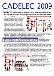
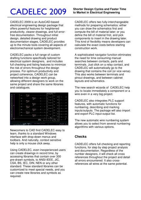
<strong>CADELEC</strong> <strong>2009</strong> is an AutoCAD-based<br />
electrical engineering design package that<br />
offers powerful features for heightened<br />
productivity, clearer drawings, and full errorfree<br />
documentation. Throughout initial<br />
design, detailed drawing and product<br />
documentation stages, <strong>CADELEC</strong> provides<br />
up to the minute tools covering all aspects of<br />
electromechanical system development.<br />
<strong>CADELEC</strong> packs a full range of custom<br />
drafting functions specifically tailored for<br />
electrical system designers, and includes<br />
full checking and listing features to minimize<br />
the risk of errors throughout the design<br />
process. For optimum productivity and<br />
project coherence, <strong>CADELEC</strong> can be<br />
networked into a design work group,<br />
allowing different designers to work on the<br />
same project and share the same libraries<br />
and catalogues.<br />
Newcomers to CAD find <strong>CADELEC</strong> easy to<br />
learn, thanks to a standard Windows<br />
interface with drop-down menus and<br />
toolbars. And naturally, context sensitive<br />
help is only a mouse click away.<br />
Using <strong>CADELEC</strong>, even inexperienced users<br />
can create drawings in record time, by<br />
accessing libraries that contain over 300<br />
pre-drawn symbols, to ANSI-IEEE, JIC,<br />
CSA, BS, IEC, DIN, NEN or any other<br />
standard. These standard libraries can be<br />
customized to meet special needs, and you<br />
can create new libraries and symbols as<br />
required.<br />
Shorter Design Cycles and Faster Time<br />
to Market in Electrical Engineering<br />
<strong>CADELEC</strong> offers two fully-interchangeable<br />
methods for preparing schematics: either<br />
you can draw the schematics first and<br />
compute the bill of material later; or you<br />
define the bill of material first, and pick<br />
components to insert in the drawing later.<br />
This kind of flexibility means developers can<br />
calculate the exact costs before starting<br />
construction work.<br />
A sophisticated navigator function eliminates<br />
the need for time consuming manual<br />
searches between contacts, parts and<br />
terminals. Just click on a relay contact, and<br />
<strong>CADELEC</strong> will automatically go to the<br />
drawing that contains the coil (or vice versa).<br />
This also works between terminals and<br />
pinout drawings, and between cabinet<br />
layouts and schematics.<br />
The new search wizards of <strong>CADELEC</strong> help<br />
you to locate immediately a component or a<br />
wire even in a very big project.<br />
<strong>CADELEC</strong> also integrates PLC support<br />
features, with automatic functions for<br />
numbering, describing and marking<br />
inputs/outputs. The package will also import<br />
and export PLC input-output list.<br />
The new automatic wire numbering system<br />
allows you to select from several numbering<br />
algorithms with various options.<br />
Checks<br />
<strong>CADELEC</strong> offers full checking and reporting<br />
functions, for step by step project analysis<br />
and documentation. Regardless of the<br />
number designers, it will check all cross<br />
references throughout the project and detail<br />
all errors encountered. It also crossreferences<br />
all wires at the same potential.
`^abib`=OMMV<br />
Terminal and Cable management<br />
<strong>CADELEC</strong>’s terminal editor functions<br />
automatically manage all the terminals and<br />
cables in a project, allowing you to change<br />
terminal blocks, set cable and wire<br />
specifications, determine wire lengths.<br />
There are four alternatives for specifying<br />
cables, terminal strips and external devices:<br />
the new automatic Cable Linker<br />
data entry in terminal pinout drawing<br />
data entry in terminal editor (prior to<br />
generating terminal pinout drawing)<br />
dialogue box in schematic<br />
Setting cables and wires between two<br />
terminal strips or a terminal strip and an<br />
element can be done more easily now with<br />
the new Cable Linker, which lets you define<br />
a cable in one step.<br />
Schematics and terminal pinout diagrams<br />
are updated automatically, regardless of the<br />
cable specification method. And <strong>CADELEC</strong><br />
Shorter Design Cycles and Faster Time<br />
to Market in Electrical Engineering<br />
also generates terminal pinout diagrams in a<br />
choice of standard formats.<br />
Manufacturer catalogues<br />
<strong>CADELEC</strong> supports a virtually unlimited<br />
number of catalogues for each project.<br />
Entries for any device can be made in five<br />
different languages, and catalogues can be<br />
sorted by language or other criteria.<br />
The program even provides assistance for<br />
component selection, by matching electrical<br />
characteristics to symbol, then generating<br />
parts, materials and order lists automatically.<br />
You can optimize project costing by merely<br />
changing the catalogue. At the click of a<br />
button <strong>CADELEC</strong> lets you compare project<br />
costs across alternative procurement<br />
scenarios.<br />
Applying a built in filter feature, you can print<br />
specific requirement lists to analyse specific<br />
cost factors (e.g. motor system only).<br />
<strong>CADELEC</strong> comes with over 60 predefined<br />
report lists in 9 languages, and you can<br />
design your own custom report formats to<br />
meet company or client–specific standards.<br />
<strong>CADELEC</strong> can also be hooked up to<br />
external databases, such as the component<br />
inventory system, for example.<br />
Control Cabinet Layout<br />
Generating control cabinet layouts is easy<br />
using <strong>CADELEC</strong> <strong>2009</strong>. The system<br />
analyses the project for all components to<br />
be included in the cabinet, excluding any<br />
remote items such as motors etc.<br />
Using the cursor, you pick each item in turn;<br />
<strong>CADELEC</strong> <strong>2009</strong> automatically draws an<br />
outline representing that component<br />
(applying physical data from the catalogue<br />
database). You can then move the<br />
component outline to the required position<br />
on the cabinet. As you do so, the<br />
component disappears from the list of<br />
components, ensuring that there is no risk of<br />
duplication.
`^abib`=OMMV<br />
If a user removes a component in a<br />
schematic it will be flagged red in the<br />
cabinet drawing.<br />
A component which has already been<br />
placed in a cabinet is no longer available.<br />
Modular structure<br />
<strong>CADELEC</strong> <strong>2009</strong> is distributed in five<br />
modules, as described below :<br />
Drawing and Analysis Module<br />
The basic module is available together with<br />
any other module or with all of them. Within<br />
this module, the following functions are<br />
available:<br />
• Tracing of one and three phase wires.<br />
• Specify wire voltage rating.<br />
• Automatic computation of device ID's with<br />
user-selectable formulas.<br />
• Automatic re-annotation of technical data on<br />
components.<br />
• Automatic generation of over 60 reports like<br />
parts list, bills of materials, etc.<br />
• Cross-reference analysis with detection of<br />
errors such as oversaturated contacts and<br />
missing relays; generation of a crossreference-error<br />
list.<br />
• Automatic wire numbering<br />
• Automatic project plotting with user specified<br />
custom printout and a pick list for plotting<br />
selected pages of the project.<br />
• Management of colors and layers.<br />
• Automatic updating of title boxes; title boxes are<br />
fully customizable.<br />
Shorter Design Cycles and Faster Time<br />
to Market in Electrical Engineering<br />
• Links with external databases in xBase format.<br />
• Batch process on library elements.<br />
• Creation and plotting of library slides.<br />
• Printing of component labels.<br />
• Access to user-defined procedures.<br />
• Batch process on project pages.<br />
• With the powerful navigator, searching for<br />
contacts and coils belongs to history. With on<br />
mouse click, you change between the page<br />
where the contact is located to the page where<br />
its activating coil is. It works the other way<br />
around as well.<br />
• Multiple user networking with various engineers<br />
working on the same project at the same time.<br />
Cabinet Module<br />
The Cabinet module adds the following<br />
functionalities<br />
• Project costing in advance with a pre-defined bill<br />
of material (Estimate).<br />
• Inserting components from the pre-defined bill of<br />
material.<br />
• Selecting Cabinets to hold the elements in the<br />
project from the Cabinet Library.<br />
• Creating new Cabinet elements.<br />
• Semi-automatic generation of control cabinet<br />
layouts.<br />
• On-line consistency checking for components in<br />
the cabinets.<br />
• With the navigator you can change now between<br />
cabinet layout drawings and schematics. With a<br />
mouse click on an element in the cabinet<br />
drawing, you change in the schematic drawing<br />
where this element is located. The other way<br />
around works as well.<br />
Terminal and Cabling Module<br />
• Generation of connection reports (both internal<br />
circuit connections and links to external units via<br />
terminals plugs or connections).<br />
• Management of terminals, cables and wiring<br />
harnesses.<br />
• Using the navigator, you can now change<br />
between terminal pinouts and the schematics in<br />
order to find a specific terminal. Or you can go<br />
the other way around, as well.<br />
• Cable editor.<br />
• Automatic Cable Linker.<br />
• Generation of terminal pinouts drawing.
`^abib`=OMMV<br />
• Automatic generation of bridges.<br />
PLC module<br />
• Selecting PLC-s from a PLC Library.<br />
• Edit PLC addresses.<br />
• Number PLC-s and related components<br />
• Export-Import PLC input/output List.<br />
• PLC related functions.<br />
System Requirements<br />
• PC with Pentium 4 processor or better<br />
• 1GB RAM or more<br />
• Windows XP or Vista 32<br />
• AutoCAD <strong>2009</strong><br />
<strong>CADELEC</strong> <strong>2009</strong> is produced and supported<br />
by:<br />
SISCAD Inc.<br />
17, Chemin de la Chavanne<br />
CH-1196 Gland, Switzerland<br />
Tel. +41-21-824-3615<br />
WEB www.cadelec.com<br />
email sales@siscad.com<br />
Shorter Design Cycles and Faster Time<br />
to Market in Electrical Engineering