High Res PDF - Extron Electronics
High Res PDF - Extron Electronics
High Res PDF - Extron Electronics

You also want an ePaper? Increase the reach of your titles
YUMPU automatically turns print PDFs into web optimized ePapers that Google loves.
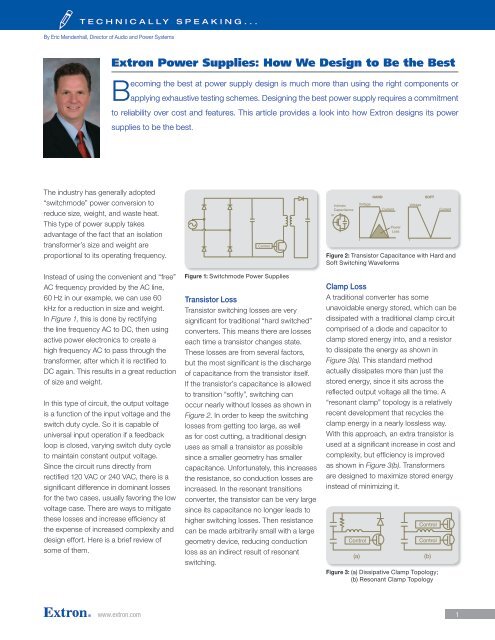
TECHNICALLY SPEAKING...<br />
By Eric Mendenhall, Director of Audio and Power Systems<br />
Ref.<br />
<strong>Extron</strong> Power Supplies: How We Design to Be the Best<br />
Becoming the best at power supply design is much more than using the right components or<br />
applying exhaustive testing schemes. Designing the best power supply requires a Ref. commitment<br />
to reliability over cost and features. This article provides a look into how <strong>Extron</strong> designs its power<br />
supplies to be the best.<br />
The industry has generally adopted<br />
“switchmode” power conversion to<br />
reduce size, weight, and waste heat.<br />
This type of power supply takes<br />
advantage of the fact that an isolation<br />
transformer’s size and weight are<br />
proportional to its operating frequency.<br />
Instead of using the convenient and “free”<br />
AC frequency provided by the AC line,<br />
60 Hz in our example, we can use 60<br />
kHz for a reduction in size and weight.<br />
In Figure 1, this is done by rectifying<br />
the line frequency AC to DC, then using<br />
active power electronics to create a<br />
high frequency AC to pass through the<br />
transformer, after which it is rectified to<br />
DC again. This results in a great reduction<br />
of size and weight.<br />
In this type of circuit, the output voltage<br />
is a function of the input voltage and the<br />
switch duty cycle. So it is capable of<br />
universal input operation if a feedback<br />
loop is closed, varying switch duty cycle<br />
to maintain constant output voltage.<br />
Since the circuit runs directly from<br />
rectified 120 VAC or 240 VAC, there is a<br />
significant difference in dominant losses<br />
for the two cases, usually favoring the low<br />
voltage case. There are ways to mitigate<br />
these losses and increase efficiency at<br />
the expense of increased complexity and<br />
design effort. Here is a brief review Fig of 3<br />
some of them.<br />
Xfmr<br />
Secondary<br />
Fig 1<br />
Fig 1<br />
Control<br />
Figure 1: Switchmode Fig Power 3 Supplies<br />
Control<br />
Fig Transistor 1 Loss<br />
Transistor switching Fig 3 losses are very<br />
significant for traditional “hard switched”<br />
Control<br />
converters. This means there are losses<br />
Xfmr<br />
Xfmr<br />
each time a transistor changes state.<br />
Secondary Output Secondary<br />
Output<br />
These losses are from several factors,<br />
Control<br />
but the most (a) significant is the discharge (b)<br />
of Xfmr capacitance from Fig the Xfmr6<br />
transistor itself. Intrinsic<br />
Secondary Output Secondary<br />
Output<br />
If the transistor’s capacitance is allowed<br />
Transistor<br />
to transition (a) “softly”, switching (b) can<br />
occur nearly without Fig 6 losses as shown in<br />
Figure 2. In order to keep the switching<br />
losses from getting too large, as well<br />
as for cost cutting, a traditional design<br />
uses as small a transistor as possible<br />
since a smaller geometry has smaller<br />
capacitance. Unfortunately, this increases<br />
the resistance, so conduction losses are<br />
increased. In the resonant transitions<br />
converter, the transistor can be very large<br />
since its capacitance no longer leads to<br />
higher switching losses. Then resistance<br />
can be made arbitrarily small with a large<br />
geometry device, reducing conduction<br />
loss as an indirect result of resonant<br />
switching.<br />
Control<br />
Ref.<br />
Fig 4<br />
Clamp Loss (a) (b)<br />
A traditional converter Fig 2 has some<br />
Fig 5Control<br />
unavoidable energy stored, which can be<br />
Control<br />
Control<br />
dissipated with a traditional clamp circuit<br />
(a) (b)<br />
comprised of a diode and capacitor to<br />
Fig 5<br />
clamp stored energy into, and a resistor<br />
to dissipate the energy as shown in<br />
Control Control<br />
Figure 3(a). HARD This standard method SOFT<br />
(a) (b)<br />
actually Voltagedissipates<br />
more than Voltage just the<br />
Fig 7<br />
stored energy, Current since it sits across the<br />
Control Control<br />
reflected output voltage all the time. A<br />
(a) (b)<br />
“resonant clamp” topology is a relatively<br />
Power Fig 7<br />
recent development Loss that recycles the<br />
clamp energy in a nearly lossless way.<br />
t t<br />
With this approach, an extra transistor is<br />
used at a significant increase in cost and<br />
Fig 4<br />
complexity, but efficiency is improved<br />
as shown in Figure 3(b). Transformers<br />
are designed to maximize stored energy<br />
instead of minimizing it.<br />
Control<br />
www.extron.com 1<br />
Output<br />
Xfmr<br />
Secondary<br />
Output<br />
Capacitance<br />
Fig 2<br />
Control<br />
Fig 2<br />
HARD SOFT<br />
Intrinsic<br />
Voltage<br />
Voltage<br />
Capacitance<br />
Transistor<br />
Current<br />
HARD<br />
Power<br />
Loss SOFT<br />
Intrinsic<br />
Voltaget<br />
Voltaget<br />
Capacitance<br />
Transistor<br />
Current<br />
Current<br />
Power<br />
Loss<br />
t t<br />
Figure 2: Transistor Capacitance Fig 4 with Hard and<br />
Soft Switching Waveforms<br />
Control<br />
(a) (b)<br />
Control<br />
Control<br />
Control<br />
Control<br />
Figure 3: (a) Dissipative Clamp Topology;<br />
Fig 5<br />
(b) <strong>Res</strong>onant Clamp Topology<br />
Current<br />
Current
trinsic<br />
apacitance<br />
Diode Loss<br />
The conversion of transformer AC to<br />
output DC has traditionally been handled<br />
Control<br />
by a simple diode, but at the expense of<br />
an additional Control transistor, we can Control reduce<br />
the conduction losses dramatically as<br />
shown (a) in Figure 4. The timing of (b) this<br />
added transistor must be carefully<br />
synchronized to the Fig main 5 transistor, but<br />
losses can be cut an order of magnitude.<br />
Startup Circuit Loss<br />
Figure 5 shows a startup resistor. This<br />
is used to supply start-up power to the<br />
12 V control system from the rectified<br />
AC line voltage, 170 VDC to 340 VDC.<br />
This is only 4% to 8% efficient, but the<br />
worst part is that the resistor stays in<br />
circuit, dissipating power for the life of the<br />
product. The 240 VAC case dissipates<br />
4 times the 120 VAC case, due to V2/R.<br />
<strong>High</strong> efficiency designs use an actively<br />
controlled high voltage current source to<br />
start up the control system that dissipates<br />
no power during active mode.<br />
2<br />
Voltage<br />
Xfmr<br />
Secondary<br />
HARD Fig 3<br />
SOFT<br />
Current<br />
Power<br />
Loss<br />
t t<br />
Control<br />
Output<br />
Xfmr<br />
Secondary<br />
Output<br />
Fig 4<br />
(a) (b)<br />
Fig 6<br />
Figure 4: (a) Diode Loss in output<br />
(b) Diode loss reduced with transistor<br />
Fig 7<br />
Voltage<br />
Control Control<br />
(a) (b)<br />
Figure 5: Startup Loss Eliminated by replacing<br />
resistor in (a) with transistor (b)<br />
Current<br />
Control<br />
Transformer Loss<br />
Power transformer losses can be<br />
reduced simply by accommodating<br />
the size and cost of a larger part. If<br />
the design is not competing on power<br />
(a) (b)<br />
density or cost minimization, this is a<br />
good choice.<br />
Fig 7<br />
TECHNICALLY SPEAKING...<br />
(a) (b)<br />
Fig 5<br />
Control<br />
Control<br />
Control Control<br />
Thermal Management Simplification<br />
Another benefit of increased efficiency,<br />
or reduced dissipation, is that thermal<br />
management can be simplified.<br />
Traditional designs often require the<br />
mounting of a transistor to a dedicated<br />
heatsink. This then requires a thermal<br />
insulator and a nut and screw<br />
combination for mounting. Then some<br />
type of locking nut must be used. Due<br />
to repeated thermal expansion and<br />
contraction, a compression washer<br />
must be used to ensure proper force is<br />
applied. To maintain electrical isolation, a<br />
shoulder washer is used. All this mass is<br />
Traditional Design<br />
Insulating Bushing<br />
Plain Washer<br />
Simplified Design<br />
Insulator<br />
Spring Washer<br />
Nut<br />
Figure 6: Thermal management simplification<br />
then affixed to the circuit board somehow<br />
(as shown in Figure 6), but it can be<br />
susceptible to shock and vibration,<br />
causing broken leads.<br />
A more robust approach involves using<br />
surface mount power transistors and<br />
diodes, and using the PCB copper area<br />
for a heatsink. If the dissipation is low<br />
enough, this approach removes all hand<br />
labor and human error from the process,<br />
leaving just the highly mature and reliable<br />
process of a solder interface with a low<br />
profile result that is much less susceptible<br />
to shock and vibration.<br />
Operating Temperature<br />
and Life Expectancy<br />
All the efficiency improvements result<br />
in lower power draw, but the benefit of<br />
increased efficiency goes much farther<br />
than that. Heat accelerates component<br />
aging; a cooler product lasts longer and<br />
Fig 7<br />
Screw<br />
Washer<br />
Insulating Bushing<br />
Device<br />
Heatsink
Figure 7: Loss Summary<br />
TECHNICALLY SPEAKING...<br />
Transistor<br />
Switching<br />
Loss<br />
Transistor<br />
Conduction<br />
Loss<br />
Clamp<br />
Loss<br />
Diode<br />
Loss<br />
Startup<br />
<strong>Res</strong>istor<br />
Loss<br />
Transformer<br />
Switching<br />
Loss<br />
Transformer<br />
Conduction<br />
Loss<br />
Operating<br />
Temperature<br />
Failure Rate<br />
is more reliable. The general relationship<br />
is a doubling of lifetime for every 10˚C<br />
temperature reduction. The benefits<br />
of high efficiency are seen as reduced<br />
failure rate and increased life expectancy.<br />
New Standard of Efficiency: Level V<br />
The US Environmental Protection<br />
Agency’s ENERGY STAR program has<br />
long been the standard of efficiency for<br />
power supplies. In 2010 the program<br />
was phased out with the advent of other<br />
federal minimum efficiency standards<br />
mandated for external power supplies<br />
that meet or exceed current ENERGY<br />
STAR standards. A new standard for<br />
indicating a power supply’s efficiency<br />
level has been adopted by the EPA and<br />
by the EU. The latest efficiency standard<br />
<strong>High</strong><br />
Very<br />
<strong>High</strong><br />
<strong>High</strong><br />
TRADITIONAL<br />
DESIGN<br />
120VAC<br />
Very<br />
<strong>High</strong><br />
240 VAC<br />
HIGH EFFICIENCY<br />
DESIGN<br />
120VAC-240VAC<br />
is Level V, which requires testing of noload<br />
power consumption as well as the<br />
average efficiency. Average efficiency is<br />
the unweighted average of the efficiencies<br />
measured at 25%, 50%, 75% and 100%<br />
load. This rating system is now part of the<br />
international energy efficiency marking<br />
protocol being implemented worldwide.<br />
Electromagnetic Interference (EMI)<br />
EMI is a concern in switchmode power<br />
converters to a far greater degree than<br />
it is in linear supplies. A switchmode<br />
circuit operating with 60 kHz square<br />
waves produces harmonics easily<br />
up to the 60 MHz region in the form<br />
of electrical noise, electric fields, and<br />
magnetic fields, which can interfere<br />
with operation of the very circuits that<br />
the power supply is supposed to be<br />
serving. These harmonics can also<br />
exit the product via cabling acting as<br />
unintentional antennae, or openings in the<br />
chassis. Once in the outside world, they<br />
can interfere with all types of equipment.<br />
The last 20 years have seen an industrywide<br />
focus on compliance as regulating<br />
bodies worldwide have been created or<br />
strengthened to deal with the problems<br />
of electromagnetic interference. Early<br />
designs were notoriously noisy from an<br />
EMI perspective, but again, companies<br />
were able to rise to the challenge and<br />
produce switchmode designs effectively<br />
as quiet as the old linear ones while<br />
retaining all the benefits.<br />
www.extron.com 3<br />
None<br />
<strong>Res</strong>onant Soft<br />
Switching<br />
<strong>High</strong> Low Larger Die<br />
Very<br />
<strong>High</strong><br />
None<br />
<strong>High</strong> <strong>High</strong> Low<br />
<strong>High</strong><br />
<strong>High</strong><br />
Very<br />
<strong>High</strong><br />
Very<br />
<strong>High</strong><br />
None<br />
<strong>Res</strong>onant Active<br />
Clamp<br />
Active Synchronous<br />
Rectifiers<br />
Intelligent Active<br />
Circuitry<br />
None Larger Transformer<br />
<strong>High</strong> <strong>High</strong> Low Larger Transformer<br />
<strong>High</strong><br />
Very<br />
<strong>High</strong><br />
Low<br />
<strong>High</strong> <strong>High</strong>er Low
Conclusion<br />
Reliability is a primary concern of<br />
professionals, whether they are<br />
customers, system designers, or product<br />
manufacturers. At <strong>Extron</strong>, we have<br />
adopted the philosophy regarding power<br />
supplies for our products that reliability is<br />
our primary objective, not cost, not power<br />
density, not specsmanship. To achieve<br />
this, we start with a highly efficient<br />
topology made from the highest quality<br />
components available and manufacture<br />
them with the same process used for<br />
our high-end video products, using the<br />
same care and attention to detail in every<br />
step of the process. From Purchasing to<br />
Manufacturing, from Test Engineering to<br />
Quality Assurance, <strong>Extron</strong> switchmode<br />
power supplies ensure more high quality<br />
<strong>Extron</strong> products.<br />
4<br />
Waste, W<br />
6.0<br />
5.0<br />
4.0<br />
3.0<br />
2.0<br />
1.0<br />
0.0<br />
TECHNICALLY SPEAKING...<br />
Waste Heat vs Load<br />
0% 25% 50% 75% 100%<br />
Load<br />
Traditional 12W Desktop Supply <strong>Extron</strong> Level V 12W Desktop Supply<br />
Figure 8: Comparison of Traditional versus Level V Power Supplies