624 BLD - FAAC USA
624 BLD - FAAC USA
624 BLD - FAAC USA

Create successful ePaper yourself
Turn your PDF publications into a flip-book with our unique Google optimized e-Paper software.
<strong>624</strong> <strong>BLD</strong>
INDEX<br />
1. ..WARNINGS ..................................................................................................................................................3<br />
2. ..TECHNICAL SPECIFICATIONS .......................................................................................................................3<br />
3. ..LAYOUT AND COMPONENTS OF <strong>624</strong><strong>BLD</strong> .....................................................................................................3<br />
3.1 Description of components ..................................................................................................................3<br />
4. ..ELECTRICAL CONNECTIONS ........................................................................................................................4<br />
4.1 J1 Terminal-board - Accessories (Fig. 2) ...........................................................................................4<br />
4.2 Connection of relay photocells and safety devices with “N.C.” contact ............................................... 5<br />
4.3 Connection of BUS photocells ............................................................................................................5<br />
4.4 J2 Terminal-board - Motor, flashing lamp and fan (Fig. 2) ...............................................................6<br />
4.5 J8 Connector - Motor capacitor (Fig. 2) ............................................................................................6<br />
4.6 J9 Terminal-board - Power supply (Fig. 2) ..........................................................................................6<br />
4.7 J3, J5 Rapid connectors - for opening and closing limit-switches (Fig. 2) .........................................6<br />
4.8 J6 Connector - Beam breaking sensor (Fig. 2) ....................................................................................6<br />
4.9 DS1 Frequency selector (Fig. 1) ...................................................................................................................... 6<br />
4.10 J4 Connector - for Minidec, Decoder and RP ............................................................................................. 6<br />
5. ..PROGRAMMING ..........................................................................................................................................6<br />
5.1 1st LEVEL PROGRAMMING ...................................................................................................................6<br />
5.2 Modification of the pre-setting .........................................................................................................8<br />
5.3 Setup and BUS system control ........................................................................................................................ 8<br />
5.4 2nd LEVEL PROGRAMMING .................................................................................................................9<br />
5.5 Setup for integrated Loop Detector .................................................................................................10<br />
6. ..START-UP ......................................................................................................................................................11<br />
6.1 Board LEDS check ...............................................................................................................................11<br />
6.2 Check on BUS status ...........................................................................................................................11<br />
7. ..AUTOMATED SYSTEM TEST ............................................................................................................................11<br />
8. ..MASTER-SLAVE CONFIGURATIONS ...............................................................................................................12<br />
9. ..3rd LEVEL PROGRAMMING ..........................................................................................................................13<br />
9.1 Customisation of function logic..........................................................................................................15<br />
10. PRE-SETTING VALUES ...................................................................................................................................15<br />
11. NOTES .........................................................................................................................................................16<br />
12. INTERLOCK CONNECTION ...........................................................................................................................16<br />
13. FUNCTION LOGIC TABLES ............................................................................................................................17<br />
1<br />
ENGLISH
ENGLISH<br />
Manufacturer: <strong>FAAC</strong> S.p.A.<br />
CE DECLARATION OF CONFORMITY<br />
Address: Via Calari, 10 - 40069 Zola Predosa BOLOGNA - ITALY<br />
Declares that: <strong>624</strong><strong>BLD</strong> control unit<br />
• conforms to the essential safety requirements of the following EEC directives<br />
2006/95/EC Low Voltage Directive<br />
2004/108/EC Electromagnetic Compatibility Directive<br />
Additional note:<br />
This product underwent tests in a typical uniform configuration<br />
(all products manufactured by <strong>FAAC</strong> S.p.A.).<br />
Bologna, 01 January 2010<br />
1) ATTENTION! To ensure the safety of people, it is important that you read<br />
all the following instructions. Incorrect installation or incorrect use of<br />
the product could cause serious harm to people.<br />
2) Carefully read the instructions before beginning to install the product.<br />
3) Do not leave packing materials (plastic, polystyrene, etc.) within reach<br />
of children as such materials are potential sources of danger.<br />
4) Store these instructions for future reference.<br />
5) This product was designed and built strictly for the use indicated in this<br />
documentation. Any other use, not expressly indicated here, could<br />
compromise the good condition/operation of the product and/or be<br />
a source of danger.<br />
6) <strong>FAAC</strong> declines all liability caused by improper use or use other than that<br />
for which the automated system was intended.<br />
7) Do not install the equipment in an explosive atmosphere: the presence<br />
of inflammable gas or fumes is a serious danger to safety.<br />
8) The mechanical parts must conform to the provisions of Standards EN<br />
12604 and EN 12605.<br />
For non-EU countries, to obtain an adequate level of safety, the Standards<br />
mentioned above must be observed, in addition to national legal<br />
regulations.<br />
9) <strong>FAAC</strong> is not responsible for failure to observe Good Technique in the<br />
construction of the closing elements to be motorised, or for any deformation<br />
that may occur during use.<br />
10) The installation must conform to Standards EN 12453 and EN 12445.<br />
For non-EU countries, to obtain an adequate level of safety, the Standards<br />
mentioned above must be observed, in addition to national legal<br />
regulations.<br />
11) Before attempting any job on the system, cut out electrical power.<br />
12) The mains power supply of the automated system must be fitted with an<br />
all-pole switch with contact opening distance of 3 mm or greater. Use<br />
of a 6A thermal breaker with all-pole circuit break is recommended.<br />
13) Make sure that a differential switch with threshold of 0.03 A is fitted<br />
upstream of the system.<br />
2<br />
The Managing Director<br />
A. Marcellan<br />
WARNINGS FOR THE INSTALLER<br />
GENERAL SAFETY OBLIGATIONS<br />
14) Make sure that the earthing system is perfectly constructed and connect<br />
metal parts of the closure to it.<br />
15) The automated system is supplied with an intrinsic anti-crushing safety<br />
device consisting of a torque control. Nevertheless, its tripping threshold<br />
must be checked as specified in the Standards indicated at point<br />
10.<br />
16) The safety devices (EN 12978 standard) protect any danger areas<br />
against mechanical movement Risks, such as crushing, dragging, and<br />
shearing.<br />
17) Use of at least one indicator-light (e.g. <strong>FAAC</strong>LIGHT ) is recommended<br />
for every system, as well as a warning sign adequately secured to the<br />
frame structure, in addition to the devices mentioned at point “16”.<br />
18) <strong>FAAC</strong> declines all liability as concerns safety and efficient operation of<br />
the automated system, if system components not produced by <strong>FAAC</strong><br />
are used.<br />
19) For maintenance, strictly use original parts by <strong>FAAC</strong>.<br />
20) Do not in any way modify the components of the automated system.<br />
21) The installer shall supply all information concerning manual operation<br />
of the system in case of an emergency and shall hand over to the user<br />
the warnings handbook supplied with the product.<br />
22) Do not allow children or adults to stay near the product while it is<br />
operating.<br />
23) Keep remote controls or other pulse generators away from children,<br />
to prevent the automated system from being activated involuntarily.<br />
24) Transit is permitted only when the automated system is idle.<br />
25) The user must not attempt any kind of repair or direct action whatever<br />
and contact qualified personnel only.<br />
26) Check at least every 6 months the efficiency of the system, particularly<br />
the efficiency of the safety devices (including, where foreseen, the<br />
operator thrust force) and of the release devices.<br />
27) Anything not expressly specified in these instructions is not permitted.
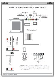
1. WARNINGS<br />
CONTROL UNIT <strong>624</strong> <strong>BLD</strong><br />
Attention: Before attempting any work on the control unit (connections, maintenance), always turn off power.<br />
- Install, upstream of the system, a differential thermal breaker with adequate tripping threshold.<br />
- Connect the earth cable to the terminal on the J9 connector of the unit (see fig.2).<br />
- Always separate power cables from control and safety cables (push-button, receiver, photocells, etc.). To avoid any electrical<br />
noise, use separate sheaths or a screened cable (with the screen earthed).<br />
2. TECHNICAL SPECIFICATIONS<br />
Power supply<br />
voltage *<br />
230 V~ (+6% -10%) - 50/60 Hz<br />
or<br />
115 V~ (+6% -10%) - 50/60 Hz<br />
Absorbed power 7 W<br />
Motor max. load 1000 W<br />
Power supply<br />
for accessories<br />
Accessories max.<br />
current<br />
Operating ambient<br />
temperature<br />
Protection<br />
fuses *<br />
24 Vdc<br />
500 mA<br />
from -20°C to +55°C<br />
F1 = F 10A - 250V F2 = T 0,8A - 250V<br />
or<br />
F1 = F 20A - 120V F2 = T 0,8A - 120V<br />
Work time Programmable (from 0 to 4 minutes)<br />
Pause time Programmable (from 0 to 4 minutes)<br />
Motor power Programmable on 50 levels<br />
Programming<br />
Rapid connector<br />
Programmable<br />
outputs<br />
3 programming levels for greater<br />
flexibility of use<br />
Coupling for 5-pin Minidec board,<br />
Decoder, Receiver RP/RP2<br />
4 programmable outputs<br />
in 18 different functions<br />
Management of slow-downs,<br />
multifunction display, BUS technology<br />
Features<br />
and INTEGRATED METALLIC MASS<br />
DETECTOR<br />
* The power supply voltage and fuses depend on the version<br />
purchased<br />
3<br />
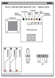
3. LAYOUT AND COMPONENTS OF <strong>624</strong><strong>BLD</strong><br />
3.1 DESCRIPTION OF COMPONENTS<br />
Fig. 1<br />
DL SIGNALS AND PROGRAMMING DISPLAY<br />
LED INPUT STATUS CONTROL LEDs<br />
J1 LOW-VOLTAGE TERMINAL BOARD<br />
J2<br />
TERMINAL BOARD FOR CONNECTION OF MOTOR, FLASHING<br />
LAMP AND FAN<br />
J3 OPENING LIMIT-SWITCH CONNECTOR<br />
J4 CONNECTOR FOR DECODER MINIDEC / RP RECEIVER<br />
J5 CLOSING LIMIT-SWITCH CONNECTOR<br />
J6 CONNECTOR FOR ROD BREAKING SENSOR<br />
J8 CONNECTOR FOR MOTOR THRUST CAPACITOR<br />
J9 TERMINAL-BOARD FOR 230 VAC POWER SUPPLY<br />
DS1 LOOP 1 and LOOP 2 FREQUENCIES SELECTOR<br />
F1 FUSE FOR MOTORS AND TRANSFORMER PRIMARY WINDING (F 5A)<br />
F2 FUSE FOR LOW VOLTAGE AND ACCESSORIES (T 800mA)<br />
F PROGRAMMING PUSH-BUTTON “F”<br />
+ PROGRAMMING PUSH-BUTTON “+”<br />
- PROGRAMMING PUSH-BUTTON “-”<br />
TF1 TRANSFORMER<br />
ENGLISH
ENGLISH<br />
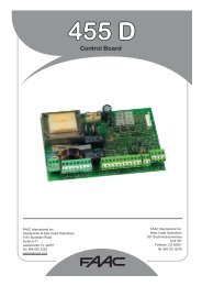
4. ELECTRICAL CONNECTIONS<br />
BEAM<br />
BREAKER<br />
To connect the<br />
photocells and<br />
safety devices,<br />
consult paragraph<br />
4.2.<br />
4<br />
FAN<br />
230 V~<br />
or 115 V~<br />
60W max *<br />
MOTOR THRUST<br />
CAPACITOR<br />
BLUE<br />
MOTOR<br />
* 230 V~ board version<br />
or 115 V~ board version<br />
4.1. J1 TERMINAL-BOARD - ACCESSORIES (FIG. 2)<br />
LOOP 1 - Magnetic loop LOOP 1 (OPEN - terminals 1-2): it activates the OPENING function<br />
LOOP 2 - Magnetic loop LOOP 2 (SAFETY/CLOSE - terminals 3-4): it activates the SAFETY/CLOSING function<br />
OPEN - “Opening” Command (N.O. - terminal 5): this refers to any pulse generator ( e.g.: push-button) which, by closing<br />
a contact, commands the barrier to close and/or open.<br />
CLOSE - “Closing” Command (N.O. - terminal 6): this refers to any pulse generator (e.g.: push-button) which, by closing<br />
a contact, commands the barrier to close.<br />
FSW - Closing safety-devices contact (N.C. - terminal 7). The purpose of the closing safety devices is to protect the<br />
barrier movement area during closure, by reversing motion. They are never tripped during the opening cycle. If the closing<br />
Safety devices are engaged when the automated system is in open status, they prevent the closing movement.<br />
If closing safety devices are not connected, jumper connect the FSW and GND terminals (fig. 6).<br />
230 V~<br />
or 115 V~<br />
50/60 Hz *<br />
STOP - STOP contact (N.C. - terminal 8): this refers to any device (e.g.: push-button) which, by opening a contact, can<br />
stop the motion of the automated system.<br />
If stop safety devices are not connected, jumper connect the STOP and GND terminals (fig. 6).<br />
EMERGENCY - EMERGENCY contact (N.C- terminal 9): this refers to any switch which, by being activated in emergency<br />
state, opens the barrier and stops its movement until the contact is restored.<br />
If emergency safety devices are not connected, jumper connect the EMERGENCY and GND terminals (fig. 6).<br />
GND ( terminals 10-11-19) - Negative contact for feeding accessories<br />
24 Vdc ( terminals 12-13)- Positive contact for feeding accessories<br />
Max. load of accessories: 500 mA. To calculate absorption values, refer to the instructions for individual<br />
accessories<br />
OUT 1 - Output 1 GND open-collector (terminal 14): The output can be set in one of the functions described in the<br />
2nd programming level (see par. 5.2.). Default value is FAILSAFE. Maximum load: 24 Vdc with 100 mA.<br />
OUT 2 - Output 2 GND open-collector (terminal 15): The output can be set in one of the functions described in the<br />
2nd programming level(see par. 5.2.). Default value is CLOSED beam. Maximum load: 24 Vdc with 100 mA.<br />
OUT 3 - RELAY Output 3 (terminal 16-17): The output can be set in one of the functions described in the 2nd programming<br />
level (see par. 5.2.). Default value is INDICATOR LIGHT: Maximum load: 24 Vdc or Vac with 500 mA.<br />
To avoid endangering correct operation of the system, do not exceed the indicated power indicated in fig. 2.<br />
OUT 4 - Output 4 open-collector +24Vdc (terminal 18): The output can be set in one of the functions described in the<br />
2nd programming level (see par. 5.2.). The default value for ALL THE PRE-SETTINGS is BUS COMMUNICATION. Maximum<br />
load: 24 Vdc with 100 mA.<br />
Fig. 2
4.2.CONNECTION OF RELAY PHOTOCELLS AND SAFETY DEVICES WITH “N.C.” CONTACT<br />
The <strong>624</strong> <strong>BLD</strong> board envisages the connection of closing safety devices which are tripped only during the barrier closing<br />
movement, and are therefore suitable for protecting the closing zone against the risk of impact.<br />
If two or more safety devices (NC contacts) have to be connected, put them in series with each other as<br />
shown in figures 3, 4, 5 under the heading “SAFE”.<br />
Connection of 1 pair of closure photocells Connection of 2 pairs of closure photocells<br />
Connection of 1 pair of closure photocells<br />
with FAIL SAFE facility<br />
Fig. 3<br />
Fig. 4<br />
To be set in the 2nd programming level : FS = Y and o1= 00<br />
4.3.CONNECTION OF BUS PHOTOCELLS<br />
5<br />
LOOP 1<br />
LOOP 2<br />
LOOP 2<br />
LOOP 1<br />
1 2 3 4 5<br />
J1<br />
OPEN A<br />
Connection of no safety device<br />
FSW<br />
CLOSE<br />
6 7<br />
STOP<br />
EMERGENCY<br />
GND<br />
GND<br />
+24 V<br />
+24 V<br />
8 9 10 11 12 13 14 15 16 17 18 19<br />
Photocells using BUS technology are connected to the <strong>624</strong> <strong>BLD</strong> control unit ALL IN PARALLEL as shown in Fig. 7 through<br />
single power/communication line.<br />
The BUS photocells do not have connection polarity.<br />
Up to a maximum of 8 pairs of BUS photocells can be connected to the board.<br />
The photocells are subdivided by quantity into the following groups:<br />
Pairs of closure photocells: max 7<br />
Pairs of photocells for OPEN pulse: max 1<br />
Make sure that at the 2nd<br />
programming level:<br />
o4 = 00 and P4 = no<br />
1st Pair of photocells 2nd Pair of photocells<br />
OUT 1<br />
OUT 2<br />
OUT 3<br />
OUT 3<br />
OUT 4<br />
Fig. 5<br />
GND<br />
Fig. 6<br />
Fig. 7<br />
ENGLISH
ENGLISH<br />
After positioning of the BUS technology photocells, select<br />
the address of each pair through the combination of the<br />
DIP-SWITCHES present on each photocell.<br />
Set THE SAME DIP-SWITCH ADDRESS<br />
chosen on both the transmitter and the<br />
receiver of the same pair.<br />
Make sure that there are not two or<br />
more pairs of photocells with the same<br />
address<br />
If no BUS accessory is used, leave terminals<br />
18 and 19 free.<br />
Table 4 shows the programming of the dip-switches present<br />
within the transmitter and receiver of the BUS photocells.<br />
Tab. 4 - Address of PAIRS of BUS photocells<br />
DIP-SWITCH<br />
TX<br />
SAME<br />
ADDRESS<br />
Dip1 Dip2 Dip3 Dip4<br />
Pair<br />
number<br />
ON OFF OFF OFF 1st pair<br />
DIP-SWITCH<br />
RX<br />
Type<br />
ON OFF OFF ON 2nd pair<br />
ON OFF ON OFF 3rd pair<br />
ON OFF ON ON 4th pair<br />
CLOSURE<br />
Photocells<br />
ON ON OFF OFF 5th pair<br />
ON ON OFF ON 6th pair<br />
ON ON ON OFF 7th pair<br />
ON ON ON ON<br />
Single<br />
Pair<br />
OPEN<br />
PULSE<br />
To make the installed Bus accessories<br />
operational, perform on-board<br />
memorisation as explained in chapter<br />
5.3.<br />
4.4. J2 TERMINAL-BOARD - MOTOR, FLASHING LAMP<br />
AND FAN (FIG. 2)<br />
M (COM-MOT1-MOT2): Motor Connection<br />
LAMP (LAMP-COM): Flashing lamp output<br />
FAN (FAN-COM): Fan output<br />
4.5. J8 CONNECTOR - MOTOR CAPACITOR (FIG. 2)<br />
Rapid connector for connecting the motor thrust capacitor.<br />
4.6. J9 TERMINAL-BOARD - POWER SUPPLY (FIG. 2)<br />
PE : Earth connection<br />
N : Power supply 230 V~ or 115 V~( Neutral )<br />
L : Power supply 230 V~ or 115 V~( Line )<br />
For correct operation, the board must<br />
be connected to the earthing conductor<br />
present in the system. Install, upstream<br />
of the system, a differential thermal<br />
breaker.<br />
4.7. J3, J5 RAPID CONNECTORS - FOR OPENING AND<br />
CLOSING LIMIT-SWITCHES (FIG. 2)<br />
Quick-fit connector for connection of the opening (J3) and<br />
closing (J5) limit-switches.<br />
6<br />
4.8. J6 CONNECTOR - BEAM BREAKING SENSOR (FIG. 2)<br />
Quick-fit connector for connecting the beam breaking sensor<br />
(where present). If this sensor is absent, leave the supplied<br />
jumper in place.<br />
4.9. DS1 FREQUENCY SELECTOR (FIG. 1)<br />
DIP-SWITCH selector used to set a HIGH or LOW working<br />
frequency of the vehicle loop detectors. Consult chapter<br />
5.5.<br />
4.10. J4 CONNECTOR - FOR MINIDEC, DECODER AND RP<br />
It is used for rapid connection of Minidec, Decoder and RP/<br />
RP2 Receivers.<br />
If you are using an RP2 twin-channel receiver, you will be able<br />
to directly command the automated system’s OPEN and<br />
CLOSE from a twin-channel radio control.<br />
If using a single-channel RP type receiver, only OPEN can be<br />
commanded.<br />
Fit the accessory with the component side directed toward<br />
the board interior.<br />
Insert and remove the boards ONLY after<br />
cutting power.<br />
An example of a radio accessory connection<br />
RP / RP2<br />
<strong>624</strong><strong>BLD</strong><br />
5. PROGRAMMING<br />
To programme the operation of the automated system, the<br />
“PROGRAMMING” mode must be accessed.<br />
Programming is in three parts: 1st LEVEL, 2nd LEVEL and 3rd<br />
LEVEL.<br />
modification of the programming<br />
parameters is immediately effective,<br />
whereas definitive memory-storage occurs<br />
only on exiting programming and returning<br />
to the view of the automated system status.<br />
If you cut power to the unit before returning<br />
to view the status, all the modifications made<br />
will be lost.<br />
J4<br />
Fig. 8<br />
You can return to viewing the status from<br />
any point of programming at any level, by<br />
pressing keys F and - simultaneously.<br />
5.1. 1ST LEVEL PROGRAMMING<br />
To access 1st LEVEL PROGRAMMING, use push-button F:<br />
• if you press it (and hold it down), the display shows the<br />
name of the first function.<br />
• if you release the push-button, the display shows the<br />
value of the function, which can be changed with keys<br />
+ and -.
• if you press F again (and hold it down), the display shows<br />
the name of the next function, etc.<br />
• when you reach the last function, press the push-button<br />
F to exit programming, and the display resumes showing<br />
the inputs status.<br />
1ST LEVEL PROGRAMMING<br />
Display Function Default<br />
dF<br />
bu<br />
LO<br />
PA<br />
LOADING PARAMETERS:<br />
00 Neutral condition<br />
0 1 Default <strong>FAAC</strong> 1 loaded<br />
02 Default RESERVED FOR <strong>FAAC</strong><br />
03 Default <strong>FAAC</strong> CITY loaded<br />
04 Default <strong>FAAC</strong> CITY K loaded<br />
05 Default J275 loaded<br />
06 Default J275K loaded<br />
LEAVE AT 00 IF YOU DO NOT WISH TO MAKE ANY<br />
CHANGE TO THE PROGRAMMING.<br />
For an explanation of the dF parameter<br />
refer to page 8 chapter 5.2.<br />
BUS ACCESSORY MENU<br />
For an explanation of this parameter refer to<br />
page 8 chapter 5.3.<br />
FUNCTION LOGICS:<br />
A Automatic<br />
A1 Automatic 1<br />
E Semiautomatic<br />
P Parking<br />
PA Parking automatic<br />
Cn Condo<br />
CA Condo automatic<br />
rb Faac-City ( traffic bollard logic )<br />
C Dead-man<br />
r Remote<br />
Cu Custom<br />
PAUSE TIME:<br />
This operates only if an automatic<br />
logic was selected. Can be adjusted<br />
from 0 to 59 sec. in 1 second steps.<br />
Subsequently, the display changes to<br />
show minutes and tenths of a second<br />
(separated by a dot) and time is adjusted<br />
in 10 second steps, up to the maximum<br />
value of 4.1 minutes.<br />
e.g. if the display shows 2.5, the pause<br />
time will be 2 min and 50 sec.<br />
FO POWER:<br />
Adjusts motor power.<br />
01 = minimum power<br />
50 = maximum power<br />
L1<br />
LOOP 1:<br />
If this function is enabled, the loop<br />
connected to the Loop1 input will have<br />
the OPEN function.<br />
Y = loop1 active<br />
no = loop1 not active<br />
Attention: if the function is not enabled,<br />
loop1 status will nevertheless be available<br />
on one of the outputs, if appropriately set<br />
(see second level programming).<br />
00<br />
E<br />
20<br />
50<br />
no<br />
7<br />
Display Function Default<br />
L2<br />
H1<br />
H2<br />
S1<br />
S2<br />
St<br />
LOOP 2:<br />
If this function is enabled, the loop<br />
connected to Loop2 input will have the<br />
SAFETY/CLOSE function, i.e. it will operate<br />
as SAFETY during the closing stage, and<br />
will command CLOSE to the board at<br />
release.<br />
Y = loop2 active<br />
no = loop2 not active<br />
Attention: if the function is not enabled,<br />
loop2 status will nevertheless be available<br />
on one of the outputs, if appropriately<br />
set.<br />
BOOST LOOP 1 FUNCTION<br />
Y = Active no = Not active<br />
Thanks to this function you can increase<br />
the sensitivity level at the moment of<br />
detection. When the vehicle leaves the<br />
loop, the sensitivity returns to the selected<br />
level. This system holds the detection<br />
contact even in the event of very high<br />
vehicles as well as during the passage of<br />
a tractor with trailer.<br />
BOOST LOOP 2 FUNCTION<br />
Y = Active no = Not active<br />
See BOOST LOOP1 function.<br />
SENSITIVITY LOOP 1<br />
Regulates the sensitivity of the loop:<br />
01 = minimum<br />
10 = maximum<br />
SENSITIVITY LOOP 2<br />
Regulates the sensitivity of the loop:<br />
01 = minimum<br />
10 = maximum<br />
no<br />
no<br />
no<br />
05<br />
05<br />
AUTOMATED SYSTEM STATUS:<br />
Exit programming,<br />
memory storage of data set and return to<br />
automated system status view.<br />
00 Closed<br />
01 Opening pre-flashing<br />
02 Opening<br />
03 Open<br />
04 In pause<br />
05 Closing pre-flashing<br />
06 Closing<br />
07 Stopped ready to close<br />
08 Stopped ready to open<br />
09 Emergency opening<br />
10 Closing safety device in operation<br />
The display of the automated system status St is of<br />
fundamental importance for the operator assigned<br />
to installation/maintenance, to distinguish the logical<br />
processes the board performs during movements.<br />
If, for example, the automated system is in CLOSED<br />
state 00 must be shown on the display. On reaching<br />
the command OPEN, the display will change to<br />
01, if pre-flashing is enabled, or directly to 02<br />
(the OPENING movement), to then display 03 on<br />
reaching the OPEN position.<br />
ENGLISH
ENGLISH<br />
Example of sequence of states displayed starting from barrier<br />
closed:<br />
00 Closed 02 Opening<br />
03 Open<br />
04 Pause (if present)<br />
06 Closing<br />
In the sequence, states 01 and 05 are not shown; these<br />
correspond to pre-flashing at opening and at closing,<br />
respectively.<br />
5.2. MODIFICATION OF THE PRE-SETTING<br />
The modification of the dF parameter enables you to<br />
automatically load 6 different configurations modifying all<br />
programming values at every level with preset values.<br />
This possibility is a convenient starting point for subsequent<br />
rapid ‘fine tuning’ of the <strong>624</strong> <strong>BLD</strong> for functioning with 6<br />
different types of installation.<br />
6 PRE-SETTINGS may be selected:<br />
01 Default <strong>FAAC</strong> for barriers<br />
02 Default RESERVED FOR <strong>FAAC</strong><br />
03 Default for the <strong>FAAC</strong> CITY 275 H600 and H800 range<br />
04 Default for <strong>FAAC</strong> CITY 275 H700 K<br />
05 Default for J275<br />
06 Default for J275K<br />
To implement loading of the values of one of the 6<br />
pre-settings, select the required pre-setting ( 01, 02 , 03,<br />
04 , 05 , 06 ) and exit 1st level programming.<br />
EXAMPLE: selecting 01 and exiting 1st level programming, all<br />
the <strong>FAAC</strong> default values which can be found in the 1st, 2nd<br />
and 3rd level tables in the “Default” column are loaded. The<br />
<strong>624</strong> <strong>BLD</strong> is therefore configured for movement of a barrier.<br />
THE LOADING OF A PRE-SETTING CANCELS ALL<br />
THE MODIFICATIONS PREVIOUSLY MADE AT ANY<br />
PROGRAMMING STEP. IF YOU DO NOT WISH TO<br />
LOAD ANY PRE-SETTING, LEAVE THE dF STEP<br />
AT 00.<br />
The dF, step, unlike the others, does not store<br />
the value selected but returns to show 00<br />
again, as standard condition.<br />
It is therefore not possible to identify what pre-setting was<br />
previously set.<br />
If you do not wish to load any pre-setting, ALWAYS leave<br />
the dF step at value 00 and move on to the following<br />
programming step.<br />
Ensure that you load the desired default and<br />
exit 1st level programming BEFORE modifying<br />
other steps, in order to avoid deleting all the<br />
modifications made.<br />
To learn more about the specifications of each pre-setting,<br />
refer to chapter 10 on page 15.<br />
8<br />
5.3. SETUP and BUS SYSTEM CONTROL<br />
Each time you install one or more BUS accessories (as<br />
explained in chapter 4.3) these must be stored on the<br />
board.<br />
Storage is performed as follows:<br />
- enter the first programming level as explained in chapter.<br />
5.1;<br />
- at the bu programming step, release programming<br />
push-button F and press push-button + for 1 second.<br />
The display shows -- for an instant and then returns to<br />
the standard condition indicated in fig. 10. The storage<br />
procedure is finished.<br />
The bu programming step also has the function of displaying<br />
the status of the BUS technology accessories. Figure 9<br />
indicates the exact correspondence between the segments<br />
of the display and the inputs.<br />
NOT USED<br />
FSW CL = BUS photocells<br />
closing<br />
OPEN = BUS photocell<br />
pulse generators OPEN<br />
Segment ON = closed contact<br />
Segment OFF = open contact<br />
The configuration for correct operation of<br />
the automated system should show the three<br />
horizontal segments ON as in figure 10.<br />
Fig. 10<br />
In case of engagement of the closure photocells,<br />
the upper and lower segments switch off, leaving<br />
the central segment on, as in figure 11.<br />
Fig. 11<br />
In case of engagement of the PULSE GENERATOR<br />
OPEN pair, the corresponding vertical segment<br />
switches on for the engagement time of the pair,<br />
as illustrated in figure 12.<br />
Fig. 12<br />
Fig. 9<br />
The PULSE GENERATOR OPEN pair of photocells, if engaged,<br />
commands opening of the application and prevents its<br />
closure until it is released.<br />
If no pair of BUS photocells is present on the<br />
system, the bu programming step will still<br />
show the display in figure 10.<br />
The BUS communication system uses a self-diagnostic function<br />
able to supply reports of incorrect connection or of erroneous<br />
configuration of the BUS accessories.<br />
The display shows the cc signal FLASHING<br />
when a SHORT-CIRCUIT is present along<br />
the BUS line, as in figure 13. Check the<br />
connections made (chapter.4.3).<br />
Fig. 13<br />
The display shows the Er message<br />
FLASHING, as in figure 14, if more than<br />
one pair of photocells should have the<br />
same address.<br />
Fig. 14<br />
In this latter case, check all the addresses set on all the<br />
photocells installed, referring to chapter 4.3.
5.4. 2nd LEVEL PROGRAMMING<br />
To access 2nd LEVEL PROGRAMMING, press push-button F<br />
and, while holding it down, press push-button +:<br />
• if you release the + push-button, the display shows the<br />
name of the first function.<br />
• if you also release the F push-button, the display shows the<br />
value of the function, which can be changed with keys +<br />
and -.<br />
• if you press the F key (and hold it down), the display shows<br />
the name of the next function; if you release it, the value<br />
is shown and can be modified with keys + and -.<br />
• when you reach the last function, press push-button F to<br />
exit programming, and the display resumes showing the<br />
inputs status.<br />
2ND LEVEL PROGRAMMING<br />
Display Function<br />
Default<br />
MAXIMUM THRUST TORQUE:<br />
bo the motor runs at maximum torque (ignoring<br />
torque regulation) at the initial moment of<br />
movement.<br />
Y = Active<br />
no = Excluded<br />
Y<br />
PF PRE-FLASHING:<br />
it permits activation of the flashing lamp for 5<br />
secs before the start of movement.<br />
no excluded<br />
OC before each movement<br />
PA at end of pause only<br />
SC<br />
tr<br />
t<br />
FS<br />
CL before closing<br />
SLOW CLOSING:<br />
for setting the entire closing stage at slow<br />
speed.<br />
Y = Active<br />
no = Excluded<br />
DECELERATION TIME AFTER LIMIT SWITCHES:<br />
for setting the deceleration time (in seconds)<br />
after the opening and closing limit switches<br />
have operated.<br />
Can be adjusted from 0 to 10 sec. in 1 second<br />
steps.<br />
00 = deceleration excluded<br />
10 = maximum deceleration<br />
WORK TIME (time-out):<br />
A value should be set from 5 to 10 seconds<br />
longer than the time required for the automated<br />
system to move from the closed position to the<br />
open position, and vice-versa.<br />
Can be adjusted from 0 to 59 sec. in 1 second<br />
steps.<br />
Subsequently, the display changes to show<br />
minutes and tenths of a second (separated by<br />
a dot) and time is adjusted in 10 second steps,<br />
up to the maximum value of 4.1 minutes.<br />
FAIL SAFE:<br />
If this function is activated, it enables a function<br />
test of the photocells before any automated<br />
system movement, independently of the<br />
output used. If the test fails, the automated<br />
system does not start the movement.<br />
Y = Active<br />
no = Excluded<br />
no<br />
no<br />
03<br />
20<br />
no<br />
9<br />
o1<br />
P1<br />
o2<br />
P2<br />
o3<br />
P3<br />
o4<br />
P4<br />
OUTPUT 1:<br />
The output can be set to one of the following<br />
functions:<br />
00 FAILSAFE<br />
01 INDICATOR LIGHT (lighted at<br />
opening and pause, flashing at<br />
closing and off when automated<br />
system closed).<br />
02 BEAM LIGHTING (output active<br />
with beam closed and on pause,<br />
inactive with beam open, flashing<br />
during movement)<br />
03 beam CLOSED<br />
04 beam OPEN or in PAUSE, it goes off<br />
during closing pre-flashing.<br />
05 beam MOVING AT OPENING,<br />
pre-flashing included.<br />
06 beam MOVING AT CLOSING, preflashing<br />
included.<br />
07 beam STILL<br />
08 beam in EMERGENCY status<br />
09 LOOP1 engaged<br />
10 LOOP2 engaged<br />
1 1 OPEN for <strong>624</strong> SLAVE<br />
12 CLOSE for <strong>624</strong> SLAVE<br />
13 beam DETACHED<br />
14 bollard lights<br />
15 bollard buzzer<br />
16 FCA engaged<br />
17 FCC engaged<br />
18 interlock<br />
OUTPUT 1 POLARITY:<br />
For configuring the output polarity status.<br />
Y = N.C. polarity<br />
no = N.O. polarity<br />
Note: if the output is set to FAIL-SAFE ( 00 )<br />
leave the default value no.<br />
OUTPUT 2:<br />
See output 1<br />
OUTPUT 2 POLARITY:<br />
See output 1 polarity<br />
OUTPUT 3:<br />
See output 1<br />
OUTPUT 3 POLARITY:<br />
See output 1 polarity<br />
OUTPUT 4 / BUS:<br />
If set at 00 the output is dedicated to<br />
accessories with BUS technology. Refer to<br />
chapter 4.3 on page 5 for an explanation.<br />
This output retains the possibility of<br />
configuration of output 1 with the exception<br />
of functions 11, 12 which in this case have<br />
no effect.<br />
OUTPUT 4 POLARITY:<br />
For configuring the output polarity status.<br />
Y = N.C. polarity<br />
no = = N.O. polarity (for BUS)<br />
00<br />
no<br />
03<br />
no<br />
01<br />
no<br />
00<br />
no<br />
ENGLISH
ENGLISH<br />
AS<br />
nc<br />
nC<br />
h1<br />
h2<br />
St<br />
ASSISTANCE REQUEST (coupled to the next<br />
two functions):<br />
If activated at the end of the count-down<br />
(settable with the next two functions under<br />
“Cycle programming”), it activates LAMP<br />
output for 4 sec every 30 sec. (assistance<br />
request). Can be useful for setting scheduled<br />
maintenance.<br />
Y = Active<br />
no = Excluded<br />
CYCLE PROGRAMMING IN THO<strong>USA</strong>NDS:<br />
For setting a count-down of the system<br />
operating cycles, settable value from 0 to 99<br />
(thousands of cycles). The displayed value is<br />
reset as the cycles progress, interacting with<br />
the nC value (99 nc decrementing steps<br />
correspond to one nC decrement).<br />
The function can be used combined with nC,<br />
to check the use of the system and to make<br />
use of the “Assistance request”.<br />
CYCLE PROGRAMMING IN HUNDREDS OF<br />
THO<strong>USA</strong>NDS:<br />
For setting a count-down of the system<br />
operating cycles, settable value from 0 to<br />
99 (hundreds of thousands of cycles). The<br />
displayed value is reset as the cycles progress,<br />
interacting with the nc. (1 nc decrement<br />
corresponds to 99 nC decrementing steps).<br />
The function can be used combined with nc,<br />
to check the use of the system and to make<br />
use of the “Assistance request”.<br />
HOLD TIME LOOP 1<br />
For setting the presence time on loop 1. At<br />
the end of this time the board calibrates itself<br />
and indicates “loop free” (decimal point of<br />
the units OFF). On switching on the board, an<br />
automatic reset is performed.<br />
Y = 5 minutes<br />
no = infinite<br />
HOLD TIME LOOP 2<br />
For setting the presence time on loop 2. At<br />
the end of this time, the board calibrates itself<br />
and indicates “loop free” (decimal point of<br />
the tens OFF). On switching on the board, an<br />
automatic reset is performed.<br />
Y = 5 minutes<br />
no = infinite<br />
AUTOMATED SYSTEM STATUS:<br />
Exit programming, memory storage of<br />
data and return to gate status display (see<br />
paragraph 5.1.).<br />
5.5. SETUP FOR INTEGRATED LOOP DETECTOR<br />
no<br />
00<br />
01<br />
no<br />
no<br />
The <strong>624</strong> <strong>BLD</strong> is equipped with an integrated metallic mass<br />
detector for induction detection of vehicles.<br />
Features:<br />
•galvanic<br />
separation between the electronics of the detector<br />
and of the loop<br />
•automatic<br />
alignment of the system immediately after<br />
activation<br />
•continual<br />
resetting of frequency drifts<br />
•sensitivity<br />
independent of loop inductivity<br />
•regulation<br />
of the working frequency of the loops<br />
•message<br />
of loop engaged with LED display<br />
•loop<br />
status addressable on the OUT 1, OUT 2, OUT 3 and<br />
OUT 4 outputs<br />
10<br />
Connection:<br />
Connect the loop detectors as indicated in figure 2 on page<br />
4:<br />
- Terminals 1 - 2 for LOOP 1 = loop with opening function;<br />
- Terminals 3 - 4 for LOOP 2 = loop with closing and/or closing<br />
safety function.<br />
To learn more about the effect of signals originating from the<br />
loops on the automated system, please refer to the logic<br />
tables in chapter 12.<br />
To enable the function of the connected loops, enter the<br />
1st programming level and set steps L1 and L2 in Y. To<br />
enable the function of the connected loops, enter the 1st<br />
programming level and set steps.<br />
The operating status of the loop detector is shown through the<br />
use of decimal points on the display when automated system<br />
status is displayed (step St ).<br />
CALIBRATION<br />
Each time the <strong>624</strong> <strong>BLD</strong> board is powered,<br />
the display shows the automated system<br />
status and the integrated loop detector<br />
calibrates the connected loops. Therefore,<br />
perform a calibration, removing power from<br />
the <strong>624</strong> <strong>BLD</strong> for at least 5 seconds.<br />
Calibration is shown on the display through<br />
flashing of the two points, as in figure 15.<br />
Fig. 15<br />
If one or both the magnetic loops are not installed,<br />
the loop detector is continually calibrated without<br />
this creating problems to the functioning of the<br />
board. Therefore, during display of the automated<br />
system status, one or both the decimal points will<br />
flash constantly.<br />
Once calibration has taken place, the decimal points indicate<br />
the loop status:<br />
LOOP 1 LOOP 2<br />
Point ON = Loop ENGAGED<br />
Point OFF = Loop DISENGAGED<br />
Point FLASHING = Loop NOT CONNECTED or BEING CALIBRATED<br />
REGULATION OF SENSITIVITY<br />
Regulating the sensitivity determines the variation of the<br />
inductivity, for each channel, which a vehicle must cause to<br />
activate the relative output of the detector.<br />
Regulation of sensitivity is performed separately for each<br />
channel with the aid of the two S1 and S2 parameters at<br />
the 1st programming level. You can also activate the BOOST<br />
function for both detectors. Consult chapter 5.1.<br />
REGULATION OF HOLD TIME<br />
The retaining time count starts on engagement of the loop.<br />
If, on expiry of this time, the loop is still engaged, a new<br />
calibration is performed automatically where the presence<br />
of the metallic mass on the loop no longer causes its<br />
engagement. At the end of the new calibration, the loop is<br />
considered “disengaged”.<br />
The retaining time can be regulated with the aid of the two<br />
h1and h2 parameters at the 2nd programming level.
Consult chapter 5.4<br />
FREQUENCY REGULATION and NEW BALANCING<br />
The working frequency of each of the detector channels can<br />
be regulated at two levels with the aid of the DS1 DIP- switch<br />
(see fig.1).<br />
DIP 1 ON = Loop 1 frequency LOW<br />
OFF= Loop 1 frequency HIGH<br />
DIP 2 ON = Loop 2 frequency LOW<br />
OFF= Loop 2 frequency HIGH<br />
On changing one of these DIPs, it is recommended that a<br />
new calibration be performed. In case of installation of two<br />
loops, select different frequencies for each loop.<br />
NOTES FOR CONSTRUCTION OF THE LOOPS<br />
The loop must be located at least 15 cm. from fixed metal<br />
objects, at least 50 cm. from moving metal objects and not<br />
more than 5 cm. from the road surface.<br />
Use a normal single-core cable with a section of 1.5 mm²<br />
(if the cable is buried directly, it must be double insulated).<br />
Construct a loop, preferably square or rectangular, preparing a<br />
PVC cable duct or making a track in the flooring as indicated<br />
in figure 16 (the angles must be cut at 45° to avoid cable<br />
breakage). Place the cable, performing the number of<br />
windings indicated in the table. The two ends of the cable must<br />
be intertwined (at least 20 times per metre) from the loop to the<br />
detector. Avoid any cable splicing (if it should be necessary,<br />
solder the wires and seal the junction with a thermo-shrinking<br />
mm<br />
mm<br />
Loop<br />
Perimeter<br />
No. of<br />
Windings<br />
less than 3 m 6<br />
from 3 to 4 m 5<br />
from 4 to 6 m 4<br />
from 6 to 12 m 3<br />
over 12 m 2<br />
Fig. 16<br />
11<br />
6. START-UP<br />
6.1. BOARD LEDS CHECK<br />
sheath) and keep it separate from power supply lines.<br />
Before the definitive start-up of the <strong>624</strong> <strong>BLD</strong> unit, control the<br />
activation status of the LEDs present.<br />
These LEDs indicate the status of the board inputs and have<br />
particular importance for the handling of the automated<br />
system:<br />
LED ON : CLOSED contact<br />
LED OFF : OPEN contact<br />
Figure 16 shows the configuration of<br />
the standard LEDs with the automated<br />
system CLOSED ready to open.<br />
The Emergency inputs (DL5), STOP (DL4),<br />
Photocells (DL3) and Pivot (DL8) are<br />
safety inputs with N.C. (normally closed)<br />
contacts, therefore the corresponding<br />
LEDs are ON.<br />
6.2. CHECK ON BUS STATUS<br />
Fig. 16<br />
The FCA and FCC LEDs are the N.C contacts of the limit<br />
switches which, if engaged, become open, consequently<br />
switching off the corresponding LED:<br />
With Automated system<br />
CLOSED FCC ENGAGED<br />
With Automated system<br />
OPEN<br />
Consult this paragraph if BUS photocells have been<br />
installed, as indicated in paragraph 4.3 on page 5.<br />
Enter 1st programming level and show the bu<br />
programming step on the display.<br />
This step must show three horizontal lines, confirming<br />
that all pairs of BUS photocells are not engaged.<br />
Refer to paragraph 5.3 on page 8 for further details<br />
on displaying these devices.<br />
7. AUTOMATED SYSTEM TEST<br />
FCA ENGAGED<br />
When you have finished programming, check if the system is<br />
operating correctly.<br />
Check in particular if power of the automated system is<br />
adequately adjusted and if the safety devices connected to<br />
it operate correctly.<br />
ENGLISH
ENGLISH<br />
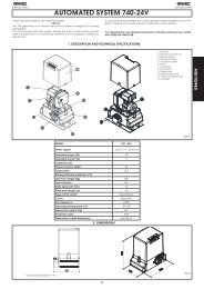
8. MASTER-SLAVE CONFIGURATIONS<br />
If installation contemplates the use of two opposing barriers to be activated at the same time on opening/ closing, one of<br />
the connection diagrams shown below should be used, depending on the control boards used to move the barriers.<br />
By MASTER equipment is meant the control board to which all the pulse generators and safety devices are connected.<br />
By SLAVE equipment is meant the control board which is controlled by the MASTER through pulse inputs, while the safety inputs<br />
are short-circuited.<br />
12<br />
3rd LEVEL<br />
PROGRAMMING<br />
03 = Y<br />
Fig. 17
9. 3rd LEVEL PROGRAMMING<br />
The 3rd level programming is only used in the case of advanced customisation of the function logics already present in the<br />
memory.<br />
Before making changes at this level, be sure you fully understand the nature of the steps you wish to modify<br />
and their effect on the automated system.<br />
To access 3rd LEVEL PROGRAMMING, press push-button F and, while holding it down, press push-button + for about 10<br />
seconds. Use of the F, + and - keys is the same as for the other two programming levels.<br />
3rd LEVEL PROGRAMMING 10 secs<br />
D. Function Setting<br />
01 If you enable this function, automatic closure occurs after pause time.<br />
Y = automatic closure<br />
no = disables<br />
If you enable this function, operation is with two different inputs: OPEN for opening and<br />
02 CLOSE for closing.<br />
Y = operation on two inputs<br />
no = disables<br />
03<br />
Activation of recognition of the levels of the OPEN and CLOSE inputs (command<br />
maintained). That is to say, the board recognises the level (for example, with OPEN<br />
maintained and STOP pressed, on release of the latter the automated system continues<br />
to open). If 03 is disabled, the board commands a manoeuvre only if the input is<br />
varied.<br />
Y = recognition of level<br />
no = recognition of the<br />
change in status<br />
Activation of DEAD MAN opening (command kept pressed). If the OPEN command is<br />
04 released, operation is stopped.<br />
Y = enables<br />
no = disables<br />
If you enable this function, an OPEN command during opening stops the movement.<br />
05 If parameter 06 is no the system is ready for opening.<br />
If parameter 06 is Y the system is ready for closing.<br />
Y = at opening stops movement<br />
no = disables<br />
If you enable this function, an OPEN command during opening reverses movement.<br />
06 If parameters 05 and 06 are no OPEN has no effect during opening.<br />
Y = at opening reverses<br />
no = disables<br />
If you enable this function, an OPEN command during the pause stops operation.<br />
07 If parameters 07 and 08 are no OPEN recharges pause time.<br />
Y = in pause stops movement<br />
no = disables<br />
If you enable this function, an OPEN command during the pause causes closure.<br />
08 If parameters 07 and 08 are no l’OPEN recharges pause time.<br />
Y = in pause closes<br />
no = disables<br />
If you enable this function, an OPEN command during closure, stops operation, otherwise it<br />
09 reverses movement.<br />
Y = stops<br />
no = reverses<br />
10<br />
DEAD MAN closing enabled (command kept pressed). If you release the CLOSE command,<br />
operation is stopped.<br />
Y = enables<br />
no = disables<br />
11<br />
If you enable this function, a CLOSE command has priority over OPEN, otherwise OPEN<br />
has priority over CLOSE.<br />
Y = enables<br />
no = disables<br />
12<br />
If you enable this function, a CLOSE command commands closure when it is released.<br />
Until CLOSE is enabled, the unit remains in closure pre-flashing.<br />
Y = closes when released<br />
no = closes at once<br />
13<br />
If you enable this function, a CLOSE command during opening stops operation, otherwise<br />
the CLOSE command commands reversing immediately or at end of opening (also see<br />
parameter 14)<br />
Y = CLOSE stops movement<br />
no = CLOSE reverses<br />
14<br />
If you enable this function, and if parameter 13 is no, the CLOSE command commands<br />
immediate closure at end of opening cycle (memory stores CLOSE). If parameters 13<br />
and 14 are no CLOSE commands immediate closure.<br />
Y = closes at the end of<br />
opening<br />
no = immediate closure<br />
15<br />
If you enable this function, when the system is stopped by a STOP, a subsequent OPEN<br />
command moves in the opposite direction. If parameter 15 is no t always closes.<br />
Y = moves in the opposite<br />
direction<br />
no = always closes<br />
16<br />
If you enable this function, during closing, the CLOSING SAFETY DEVICES stop movement<br />
and allow resumption of movement when disengaged, otherwise they immediately reverse<br />
at opening.<br />
Y = closes at disengagement<br />
no = immediate reversing<br />
17<br />
If you enable this function, the CLOSING SAFETY DEVICES command closure when<br />
disengaged<br />
(also see parameter 18).<br />
Y = closure when FSW<br />
disengaged<br />
no = disables<br />
18<br />
If you enable this function, and if parameter 17 is Y, the unit waits for the opening cycle<br />
to end before executing the closing command supplied by the CLOSING SAFETY<br />
DEVICES.<br />
Y = closes at the end of<br />
opening<br />
no = disables<br />
19<br />
If you enable this function, during closing, LOOP2 stops movement and allows it to<br />
resume at disengagement, otherwise it immediately reverses at opening.<br />
Y = closure at disengagement<br />
no = immediate reversing<br />
If you enable this function, LOOP2 commands closing when it disengages (also see<br />
20 parameter 21).<br />
Y = closes if LOOP2 is free<br />
no = disables<br />
If you enable this function, and if parameter 20 is Y , the unit waits for the opening cycle<br />
21 to end before executing the closing command supplied by LOOP2.<br />
Y = closes at the end of opening<br />
no = disables<br />
22<br />
If you enable this function, LOOP1 commands have priority over LOOP2 commands.<br />
13<br />
Y = enables<br />
no = disables<br />
ENGLISH
ENGLISH<br />
D. Function Setting<br />
23<br />
24<br />
25<br />
26<br />
27<br />
A1<br />
A2<br />
A3<br />
A4<br />
A5<br />
A6<br />
A7<br />
A8<br />
A9<br />
b0<br />
b1<br />
LOOP 1 commands opening and, at end of opening, closes if released (useful if a vehicle<br />
reverses with consecutive loops).If disabled at disengagement of LOOP 1, no closure is<br />
performed.<br />
14<br />
Y = closes if LOOP1 is free<br />
no = disables<br />
NOT USED /<br />
A.D.M.A.P function<br />
If you enable this function, the safety devices operate according to French standards.<br />
If you enable this function, during closure, the CLOSING SAFETY DEVICES stop movement<br />
and, when disengaged, reverse movement, otherwise they reverse immediately.<br />
Y = enables<br />
no = disables<br />
Y = stops movement<br />
and reverses when<br />
disengaged.<br />
no= reverses immediately.<br />
NO EFFECT /<br />
PRELAMPEGGIO:<br />
Used for adjusting - in 1 sec steps - the duration of required pre-flashing, from a minimum<br />
of 0 to a maximum of 10 seconds<br />
TIMEOUT FOR REVERSING AT CLOSURE:<br />
If you enable this function, during closing, you can decide whether to reverse or stop the<br />
movement when time out elapses (closing stroke limit not reached).<br />
OPENING AT POWER UP:<br />
In case of a power cut, when power is restored, an opening operation can be commanded<br />
by enabling this function (only if the automated system is not closed, FCC free).<br />
TIME FOR ENABLING <strong>FAAC</strong> CITY PRESSURE SWITCH (J5):<br />
This is the time after which the unit considers the signal originating from the pressure switch<br />
as the CLOSING TRAVEL-LIMIT.<br />
Can be adjusted from 0 to 59 sec. in 1 second steps. Subsequently, the display changes<br />
to show minutes and tenths of a second (separated by a dot), up to a maximum value<br />
of 4,1 minutes.<br />
DISABLING OF BOLLARD PRESSURE SWITCH AT START OF MOVEMENT:<br />
For a correct operation of the bollard, you have to disable the pressure switch check at<br />
start of the upstroke movement (time: 0.4 seconds).<br />
Set this function to Y with bollards.<br />
BOLLARD SOLENOID VALVE POWER SUPPLY CHECK (terminals 22-23):<br />
<strong>FAAC</strong> CITY K - J275K: solenoid valve output usually not supplied with power – supplied with<br />
power during downstroke.<br />
<strong>FAAC</strong> CITY - J275 standard: standard: solenoid valve output usually supplied with power<br />
– not supplied with power during downstroke.<br />
POLARITY OF OPENING TRAVEL-LIMIT STOP:<br />
Configuration of the travel-limit stop contact<br />
POLARITY OF CLOSING TRAVEL-LIMIT STOP:<br />
Configuration of the travel-limit stop contact<br />
<strong>FAAC</strong> CITY PRESSURE SWITCH ENABLE (J5):<br />
Detection of the PRESSURE SWITCH contact as safety device during the first upstroke phase<br />
and as limit switch after activation time of <strong>FAAC</strong> CITY pressure switch (parameter A4):<br />
SAFETY ONLY PRESSURE SWITCH FOR BOLLARDS (terminals 7 - GND):<br />
Recognition of PHOTOCELL contact as a safety PRESSURE SWITCH.<br />
(The contact is ignored at start of movement and at the end of the upstroke)<br />
HOLD CLOSE / HOLD OPEN FUNCTION DELAY:<br />
Delay of the activation of the HOLD CLOSE / HOLD OPEN function (see parameters b3 and<br />
b4). The count starts when the involved limit switch has been reached.<br />
If, at the end of the set time, the limit switch is involuntarily disengaged, the HOLD CLOSE /<br />
HOLD OPEN function is activated.<br />
00 = HOLD CLOSE / HOLD OPEN function activated immediately<br />
01 to 99 = minutes of count before activation of HOLD CLOSE / HOLD OPEN<br />
05<br />
Y = reversal<br />
no = block<br />
Y = opening<br />
no = stays idle<br />
4.0<br />
Y = pressure switch not<br />
active at thrust<br />
no = pressure switch always<br />
active<br />
Y = for <strong>FAAC</strong> CITY K /J275K<br />
no = for <strong>FAAC</strong> CITY<br />
standard and J275<br />
Y = NO polarity<br />
no = NC polarity<br />
Y = NO polarity<br />
no = NC polarity<br />
Y = Operation for <strong>FAAC</strong> CITY<br />
no = Standard limit switch<br />
operation<br />
Y = Operation of safety only<br />
pressure switch<br />
no = Operation of standard<br />
photocells<br />
b2 DO NOT MODIFY 30<br />
b3<br />
b4<br />
HOLD OPEN FUNCTION:<br />
If the opening limit switch is involuntarily disengaged, the board commands<br />
automatically a movement for 2 sec. to restore the position; if the opening<br />
limit switch is not engaged during this period of time, the automated system<br />
is activated max. for the operating time “t” see 2nd PROGRAMMING LEVEL:<br />
(parameter A3 recommended on Y if parameter b3 set on Y)<br />
HOLD CLOSE FUNCTION:<br />
If the closing limit switch is involuntarily disengaged, the board commands automatically a<br />
movement for 2 sec. to restore the position; if the closing limit switch is not engaged during<br />
this period of time, the automated system is activated max. for the operating time “t” see<br />
2nd PROGRAMMING LEVEL:<br />
30<br />
Y = enables<br />
no = disables<br />
Y = enables<br />
no = disables
D. Function Setting<br />
b5<br />
b6<br />
St<br />
CONTROL OF BOLLARDS SOLENOID VALVE:<br />
Function to be set to Y for J275 /J275K<br />
Function to be set to no for <strong>FAAC</strong> CITY / <strong>FAAC</strong> CITY K.<br />
EMERGENCY INPUT OPERATING LOGIC:<br />
If you activate this function, the emergency input commands a closure, which is kept until<br />
the contact is restored.<br />
If the function is not active, the emergency input commands an opening, which is kept<br />
until the contact is restored.<br />
AUTOMATED SYSTEM STATUS:<br />
Exit programming, memory storage of data and return to gate status display (see<br />
par. 5.1.).<br />
9.1. CUSTOMISATION OF FUNCTION LOGIC<br />
The 3rd programming level values vary depending on the<br />
logic selected at the first programming level.<br />
The 3rd programming level is dedicated to customisation<br />
of one of the logics selectable if non-standard behaviour of<br />
application should be needed.<br />
Procedure for implementing the modification of one or more<br />
3rd programming level parameters which customise the<br />
function of the logic set:<br />
1. Select one of the basic logics most suitable for your<br />
requirements.<br />
2. Enter the 3rd programming level and modify the required<br />
parameters.<br />
3. Exit the 3rd programming level and select logic Cu.<br />
The Cu logic activates the modifications made at the 3rd<br />
level.<br />
The following table contains the default parameters affecting<br />
the function logics.<br />
Step A A1 E P PA Cn CA rb C<br />
01 Y Y N N Y N Y Y N<br />
02 N N N Y Y Y Y Y Y<br />
03 N N N N N N N Y N<br />
04 N N N N N N N N Y<br />
05 N N Y N N N N N N<br />
06 N N Y N N N N N N<br />
07 N N N N N N N N N<br />
08 N N N N N N N N N<br />
09 N N N N N N N N N<br />
10 N N N N N N N N Y<br />
11 N N N N N N N N N<br />
12 N N N Y Y N N N N<br />
13 N N N N N N N N N<br />
14 N N N Y Y Y Y N N<br />
15 N N N N N N N N N<br />
16 N N N Y Y N N N N<br />
17 N Y N N N N N N N<br />
18 N Y N N N N N N N<br />
19 N N N Y Y N N N N<br />
20 N Y N Y Y Y Y N N<br />
21 N Y N Y Y Y Y N N<br />
22 N N N N N Y Y N N<br />
23 N N N Y Y N N N N<br />
24 N N N N N N N N N<br />
25 N N N N N N N N N<br />
26 N N N N N N N N N<br />
15<br />
10. PRE-SETTING VALUES<br />
The table below shows the values of the steps at each<br />
programming level in relation to the pre-setting chosen<br />
1st LEVEL<br />
RESERVED<br />
2nd LEVEL<br />
Default<br />
<strong>FAAC</strong>1<br />
FOR<br />
<strong>FAAC</strong><br />
Y = for J275 / J275K<br />
no= <strong>FAAC</strong> CITY / <strong>FAAC</strong> CITY K<br />
Y = active<br />
no = not active<br />
Default<br />
<strong>FAAC</strong><br />
CITY<br />
Default<br />
<strong>FAAC</strong><br />
CITY K<br />
Default<br />
J275<br />
Default<br />
J275K<br />
dF pre-setting 0 1 02 03 04 05 06<br />
bu BUS<br />
Lo logic E A1 rb rb rb rb<br />
PA pause 20 20 30 30 30 30<br />
FO power 50 50 50 50 50 50<br />
L1 loop 1 no no no no no no<br />
L2 loop 2 no no no no no no<br />
H1 loop 1 no no no no no no<br />
H2 loop 2 no no no no no no<br />
S1 sensitivity 05 05 05 05 05 05<br />
S2 sensitivity 05 05 05 05 05 05<br />
Default<br />
<strong>FAAC</strong>1<br />
RESERVED<br />
FOR<br />
<strong>FAAC</strong><br />
Default<br />
<strong>FAAC</strong><br />
CITY<br />
Default<br />
<strong>FAAC</strong><br />
CITY K<br />
Default<br />
J275<br />
Default<br />
J275K<br />
bo boost Y Y Y Y Y Y<br />
PF pre-flashing no CL no no no no<br />
SC slow closing no no no no no no<br />
tr slow-down 03 03 01 01 01 01<br />
t time out 20 20 12 12 12 12<br />
FS fail safe no no no no no no<br />
o1 output 1 00 16 15 15 15 15<br />
P1 polarity 1 no no no no no no<br />
o2 output 2 03 17 14 14 03 03<br />
P2 polarity 2 no no no no no no<br />
o3 output 3 01 01 01 01 02 02<br />
P3 polarity 3 no no no no no no<br />
o4 output 4 00 00 00 00 00 00<br />
P4 polarity 4 no no no no no no<br />
A5 assistance no no no no no no<br />
nc cycles 1. 00 00 00 00 00 00<br />
nC cycles 2. 01 01 01 01 01 01<br />
h1 hold no no no no no no<br />
h2 hold no no no no no no<br />
ENGLISH
ENGLISH<br />
3rd LEVEL<br />
Default<br />
<strong>FAAC</strong>1<br />
RESERVED<br />
FOR<br />
<strong>FAAC</strong><br />
Default<br />
<strong>FAAC</strong><br />
CITY<br />
Default<br />
<strong>FAAC</strong><br />
CITY K<br />
Default<br />
J275<br />
Default<br />
J275K<br />
01 no Y Y Y Y Y<br />
02 no no Y Y Y Y<br />
03 no no Y Y Y Y<br />
04 no no no no no no<br />
05 Y no no no no no<br />
06 Y no no no no no<br />
07 no no no no no no<br />
08 no no no no no no<br />
09 no no no no no no<br />
10 no no no no no no<br />
11 no no no no no no<br />
12 no no no no no no<br />
13 no no no no no no<br />
14 no no no no no no<br />
15 no no no no no no<br />
16 no no no no no no<br />
17 no Y no no no no<br />
18 no Y no no no no<br />
19 no no no no no no<br />
20 no Y no no no no<br />
21 no Y no no no no<br />
22 no no no no no no<br />
23 no no no no no no<br />
24 no no no no no no<br />
25 no no no no no no<br />
26 no no no no no no<br />
27 no no no no no no<br />
A1 05 0 1 05 05 05 05<br />
A2 no no no no no no<br />
A3 no no no no no no<br />
A4 4.0 4.0 04 04 4.0 4.0<br />
A5 no no Y Y Y Y<br />
A6 no no no Y no Y<br />
A7 no no Y Y no no<br />
A8 no no no Y no no<br />
A9 no no Y Y no no<br />
b0 no no no no Y Y<br />
b1 00 00 30 30 30 30<br />
b2 30 30 30 30 30 30<br />
b3 no no Y Y Y Y<br />
b4 no no no no no no<br />
b5 no no no no Y Y<br />
b6 no no no no no no<br />
16<br />
11. NOTES<br />
__________________________________________________<br />
___________________________________________________<br />
______________________________________________________________________________________________________________<br />
12. INTERLOCK CONNECTION<br />
The interlock function controls two in-line barriers (see fig.)<br />
so that the opening of a barrier is interlocked with the<br />
closure of the other barrier.<br />
The operation can be one-way or bidirectional<br />
GND<br />
OUT 4<br />
OUT 3<br />
OUT 3<br />
OUT 2<br />
OUT 1<br />
+24 V<br />
+24 V<br />
GND<br />
GND<br />
EMERGENCY<br />
STOP<br />
FSW<br />
CLOSE<br />
OPEN A<br />
LOOP 2<br />
LOOP 2<br />
LOOP 1<br />
LOOP 1<br />
GND GND<br />
OUT OUT 44<br />
OUT OUT 33<br />
OUT OUT 33<br />
OUT OUT 22<br />
OUT OUT 11<br />
+24 +24 VV<br />
+24 +24 VV<br />
GND GND<br />
GND GND<br />
EMERGENCY<br />
EMERGENCY<br />
STOP STOP<br />
FSW FSW<br />
CLOSE CLOSE<br />
OPEN OPEN AA<br />
LOOP LOOP 22<br />
LOOP LOOP 22<br />
LOOP LOOP 11<br />
LOOP LOOP 11<br />
19<br />
18<br />
16 17<br />
15<br />
14<br />
12 13<br />
10 11<br />
8 9<br />
6 7<br />
4 5<br />
2 3<br />
1<br />
19<br />
18<br />
16 17<br />
15<br />
14<br />
12 13<br />
10 11<br />
8 9<br />
6 7<br />
4 5<br />
2 3<br />
1<br />
J1<br />
J1<br />
Fig. 18<br />
For in-line barriers, enable<br />
OUT1 INTERLOCK on<br />
parameter 18 (see 2nd<br />
PROGRAMMING LEVEL) on<br />
both boards and connect<br />
them as shown in fig. 18
13. FUNCTION LOGIC TABLES<br />
Tab. 1/a<br />
LOGIC “A” PULSES<br />
AUTOMATED SYSTEM<br />
STATUS<br />
OPEN A CLOSE STOP FSW LOOP 1 LOOP 2<br />
Tab. 1/b<br />
CLOSED<br />
opens and<br />
re-closes after<br />
pause time<br />
OPENING no effect<br />
OPEN IN PAUSE<br />
CLOSING<br />
recharges pause<br />
time<br />
reverses<br />
immediately at<br />
opening<br />
no effect<br />
reverses<br />
immediately at<br />
closing<br />
closes<br />
no effect<br />
STOPPED closes closes<br />
no effect<br />
(opening<br />
disabled)<br />
stops<br />
operation<br />
stops<br />
operation<br />
stops<br />
operation<br />
no effect<br />
(opening and<br />
closing disabled)<br />
17<br />
no effect<br />
opens and<br />
re-closes after<br />
pause time<br />
no effect<br />
no effect no effect no effect<br />
recharges pause<br />
time<br />
(closing<br />
disabled)<br />
reverses<br />
immediately at<br />
opening<br />
no effect<br />
(closing<br />
disabled)<br />
recharges pause<br />
time<br />
reverses<br />
immediately at<br />
opening<br />
opens and<br />
re-closes after<br />
pause time<br />
recharges pause<br />
time<br />
(closing<br />
disabled))<br />
reverses<br />
immediately at<br />
opening<br />
no effect<br />
(closing<br />
disabled)<br />
LOGIC “A1” PULSES<br />
AUTOMATED SYSTEM<br />
STATUS<br />
OPEN A CLOSE STOP FSW LOOP 1 LOOP 2<br />
CLOSED<br />
opens and<br />
re-closes after<br />
pause time<br />
OPENING no effect<br />
OPEN IN PAUSE<br />
Tab. 1/c<br />
CLOSING<br />
recharges pause<br />
time<br />
reverses<br />
immediately at<br />
opening<br />
no effect<br />
reverses<br />
immediately at<br />
closing<br />
closes<br />
no effect<br />
STOPPED closes closes<br />
no effect<br />
(opening<br />
disabled)<br />
stops<br />
operation<br />
stops<br />
operation<br />
stops<br />
operation<br />
no effect<br />
(opening and<br />
closing disabled)<br />
no effect<br />
closes<br />
immediately at<br />
end of opening<br />
closes<br />
reverses<br />
immediately at<br />
opening<br />
no effect<br />
(closing<br />
disabled)<br />
opens and<br />
re-closes after<br />
pause time<br />
no effect<br />
recharges pause<br />
time<br />
reverses<br />
immediately at<br />
opening, closes at<br />
pause end<br />
opens and<br />
re-closes after<br />
pause time<br />
no effect<br />
closes<br />
immediately at<br />
end of opening<br />
closes<br />
reverses<br />
immediately<br />
at opening,<br />
re-closes when<br />
opening finished<br />
no effect<br />
(closing<br />
disabled)<br />
LOGIC “E” PULSES<br />
AUTOMATED SYSTEM<br />
STATUS<br />
OPEN A CLOSE STOP FSW LOOP 1 LOOP 2<br />
CLOSED opens no effect<br />
OPENING<br />
stops<br />
operation<br />
reverses<br />
immediately at<br />
closing<br />
OPEN closes closes<br />
CLOSING<br />
reverses<br />
immediately at<br />
opening<br />
no effect<br />
STOPPED closes closes<br />
In brackets the effects on the other active pulse inputs<br />
no effect<br />
(opening<br />
disabled)<br />
stops<br />
operation<br />
no effect<br />
(closing<br />
disabled)<br />
stops<br />
operation<br />
no effect<br />
(opening and<br />
closing disabled)<br />
no effect opens no effect<br />
no effect no effect no effect<br />
no effect<br />
(closing<br />
disabled)<br />
reverses<br />
immediately at<br />
opening<br />
no effect<br />
(closing<br />
disabled)<br />
closes<br />
reverses<br />
immediately at<br />
opening<br />
opens<br />
no effect<br />
(closing<br />
disabled)<br />
reverses<br />
immediately at<br />
opening<br />
no effect<br />
(closing<br />
disabled)<br />
ENGLISH
ENGLISH<br />
Tab. 1/d<br />
LOGIC “P” PULSES<br />
AUTOMATED SYSTEM<br />
STATUS<br />
OPEN A CLOSE STOP FSW LOOP 1 LOOP 2<br />
Tab. 1/e<br />
Tab. 1/f<br />
CLOSED opens no effect<br />
OPENING no effect<br />
OPEN<br />
CLOSING<br />
no effect<br />
(closing<br />
disabled)<br />
reverses<br />
immediately at<br />
opening<br />
closes<br />
immediately at<br />
end of opening<br />
closes<br />
no effect<br />
STOPPED opens closes<br />
In brackets the effects on the other active pulse inputs<br />
no effect<br />
(opening<br />
disabled)<br />
stops<br />
operation<br />
no effect<br />
(closing<br />
disabled)<br />
stops<br />
operation<br />
no effect<br />
(opening and<br />
closing disabled)<br />
18<br />
no effect<br />
opens and at end<br />
of opening closes<br />
if disengaged<br />
no effect no effect<br />
no effect<br />
(closing<br />
disabled)<br />
stops and<br />
continues to<br />
close on release<br />
no effect<br />
(closing<br />
disabled)<br />
no effect<br />
closes<br />
immediately at<br />
end of opening<br />
prevents closure closes<br />
reverses<br />
immediately at<br />
opening and<br />
closes at end<br />
of opening if<br />
disengaged<br />
opens and at end<br />
of opening closes<br />
if disengaged<br />
stops and<br />
continues to<br />
close on release<br />
no effect<br />
(closing<br />
disabled)<br />
LOGIC “PA” PULSES<br />
AUTOMATED SYSTEM<br />
STATUS<br />
OPEN A CLOSE STOP FSW LOOP 1 LOOP 2<br />
CLOSED<br />
opens and<br />
re-closes after<br />
pause time<br />
OPENING no effect<br />
OPEN IN PAUSE<br />
CLOSING<br />
STOPPED<br />
recharges pause<br />
time<br />
reverses<br />
immediately at<br />
opening<br />
opens and<br />
re-closes after<br />
pause time<br />
no effect<br />
closes<br />
immediately at<br />
end of opening<br />
closes<br />
no effect<br />
closes<br />
no effect<br />
(opening<br />
disabled)<br />
stops<br />
operation<br />
stops<br />
operation<br />
stops<br />
operation<br />
no effect<br />
(opening and<br />
closing disabled)<br />
no effect<br />
opens and at end<br />
of opening closes<br />
if disengaged<br />
no effect no effect<br />
recharges pause<br />
time<br />
(closing<br />
disabled)<br />
stops and<br />
continues to<br />
close on release<br />
no effect<br />
(closing<br />
disabled)<br />
recharges pause<br />
time<br />
reverses<br />
immediately at<br />
opening and closes<br />
at end of opening if<br />
disengaged<br />
opens and at end<br />
of opening closes<br />
if disengaged<br />
no effect<br />
closes<br />
immediately at<br />
end of opening<br />
closes<br />
stops and<br />
continues to<br />
close on release<br />
no effect<br />
(closing<br />
disabled)<br />
LOGIC “Cn” PULSES<br />
AUTOMATED SYSTEM<br />
STATUS<br />
OPEN A CLOSE STOP FSW LOOP 1 LOOP 2<br />
CLOSED opens no effect<br />
OPENING no effect<br />
OPEN<br />
CLOSING<br />
no effect<br />
(closing<br />
disabled)<br />
reverses<br />
immediately at<br />
opening<br />
closes<br />
immediately at<br />
end of opening<br />
closes<br />
no effect<br />
STOPPED opens closes<br />
no effect<br />
(opening<br />
disabled)<br />
stops<br />
operation<br />
no effect<br />
(closing<br />
disabled)<br />
stops<br />
operation<br />
no effect<br />
(opening and<br />
closing disabled)<br />
no effect opens no effect<br />
no effect no effect<br />
no effect<br />
(closing<br />
disabled)<br />
reverses at<br />
opening and<br />
closes after<br />
pause time<br />
no effect<br />
(closing<br />
disabled)<br />
closes<br />
immediately at<br />
end of opening<br />
no effect closes<br />
reverses<br />
immediately at<br />
opening<br />
opens<br />
reverses<br />
immediately at<br />
opening<br />
no effect<br />
(closing<br />
disabled)
Tab. 1/g<br />
LOGIC “CA” PULSES<br />
AUTOMATED SYSTEM<br />
STATUS<br />
OPEN A CLOSE STOP FSW LOOP 1 LOOP 2<br />
Tab. 1/h<br />
Tab. 1/i<br />
CLOSED<br />
opens and<br />
re-closes after<br />
pause time<br />
OPENING no effect<br />
OPEN IN PAUSE<br />
CLOSING<br />
STOPPED<br />
recharges pause<br />
time<br />
reverses<br />
immediately at<br />
opening<br />
opens and<br />
re-closes after<br />
pause time<br />
no effect<br />
closes<br />
immediately at<br />
end of opening<br />
closes<br />
no effect<br />
closes<br />
no effect<br />
(opening<br />
disabled)<br />
stops<br />
operation<br />
stops<br />
operation<br />
stops<br />
operation<br />
no effect<br />
(opening and<br />
closing disabled)<br />
19<br />
no effect<br />
opens and<br />
re-closes after<br />
pause time<br />
no effect no effect<br />
recharges pause<br />
time<br />
(closing<br />
disabled)<br />
reverses at<br />
opening and<br />
closes after pause<br />
time<br />
no effect<br />
(closing<br />
disabled)<br />
recharges pause<br />
time<br />
reverses<br />
immediately at<br />
opening<br />
opens and<br />
re-closes after<br />
pause time<br />
no effect<br />
closes<br />
immediately at<br />
end of opening<br />
closes<br />
reverses<br />
immediately at<br />
opening<br />
no effect<br />
(closing<br />
disabled)<br />
LOGIC “rb” PULSES<br />
AUTOMATED SYSTEM<br />
STATUS<br />
OPEN A CLOSE STOP FSW LOOP 1 LOOP 2<br />
CLOSED<br />
opens and<br />
re-closes after<br />
pause time<br />
OPENING no effect<br />
OPEN IN PAUSE<br />
CLOSING<br />
STOPPED<br />
recharges pause<br />
time<br />
reverses<br />
immediately at<br />
opening<br />
opens and<br />
re-closes after<br />
pause time<br />
no effect<br />
reverses<br />
immediately at<br />
closing<br />
closes<br />
no effect<br />
closes<br />
In brackets the effects on the other active pulse inputs<br />
no effect<br />
(opening<br />
disabled)<br />
stops<br />
operation<br />
stops<br />
operation<br />
stops<br />
operation<br />
no effect<br />
(opening and<br />
closing disabled)<br />
no effect<br />
opens and<br />
re-closes after<br />
pause time<br />
no effect<br />
no effect no effect no effect<br />
recharges pause<br />
time<br />
(closing<br />
disabled)<br />
reverses<br />
immediately at<br />
opening<br />
no effect<br />
(closing<br />
disabled)<br />
recharges pause<br />
time<br />
reverses<br />
immediately at<br />
opening<br />
opens and<br />
re-closes after<br />
pause time<br />
recharges pause<br />
time<br />
(closing<br />
disabled)<br />
reverses<br />
immediately at<br />
opening<br />
no effect<br />
(closing<br />
disabled)<br />
LOGIC “C” MAINTAINED COMMANDS PULSES<br />
AUTOMATED SYSTEM<br />
STATUS<br />
OPEN A CLOSE STOP FSW LOOP 1 LOOP 2<br />
CLOSED opens no effect<br />
OPENING / no effect<br />
OPEN<br />
CLOSING<br />
no effect<br />
(closing<br />
disabled)<br />
reverses<br />
immediately at<br />
opening<br />
closes<br />
STOPPED opens closes<br />
/<br />
no effect<br />
(opening<br />
disabled)<br />
stops<br />
operation<br />
stops<br />
operation<br />
stops<br />
operation<br />
no effect<br />
(opening and<br />
closing disabled)<br />
no effect no effect no effect<br />
no effect no effect no effect<br />
no effect<br />
Stops<br />
operation<br />
no effect<br />
(closing<br />
disabled)<br />
no effect<br />
(closing<br />
disabled)<br />
stops<br />
operation<br />
no effect<br />
(closing<br />
disabled)<br />
no effect<br />
(closing<br />
disabled)<br />
stops<br />
operation<br />
no effect<br />
(closing<br />
disabled)<br />
ENGLISH
Le descrizioni e le illustrazioni del presente manuale non sono impegnative. La <strong>FAAC</strong> si riserva il diritto, lasciando inalterate le<br />
caratteristiche essenziali dell’apparecchiatura, di apportare in qualunque momento e senza impegnarsi ad aggiornare la<br />
presente pubblicazione, le modifiche che essa ritiene convenienti per miglioramenti tecnici o per qualsiasi altra esigenza di<br />
carattere costruttivo o commerciale.<br />
The descriptions and illustrations contained in the present manual are not binding. <strong>FAAC</strong> reserves the right, whilst leaving the<br />
main features of the equipments unaltered, to undertake any modifications it holds necessary for either technical or commercial<br />
reasons, at any time and without revising the present publication.<br />
Les descriptions et les illustrations du présent manuel sont fournies à titre indicatif. <strong>FAAC</strong> se réserve le droit d’apporter à tout<br />
moment les modifications qu’elle jugera utiles sur ce produit tout en conservant les caractéristiques essentielles, sans devoir<br />
pour autant mettre à jour cette publication.<br />
Die Beschreibungen und Abbildungen in vorliegendem Handbuch sind unverbindlich. <strong>FAAC</strong> behält sich das Recht vor, ohne<br />
die wesentlichen Eigenschaften dieses Gerätes zu verändern und ohne Verbindlichkeiten in Bezug auf die Neufassung der<br />
vorliegenden Anleitungen, technisch bzw. konstruktiv/kommerziell bedingte Verbesserungen vorzunehmen.<br />
Las descripciones y las ilustraciones de este manual no comportan compromiso alguno. <strong>FAAC</strong> se reserva el derecho, dejando<br />
inmutadas las características esenciales de los aparatos, de aportar, en cualquier momento y sin comprometerse a poner al<br />
día la presente publicación, todas las modificaciones que considere oportunas para el perfeccionamiento técnico o para<br />
cualquier otro tipo de exigencia de carácter constructivo o comercial.<br />
De beschrijvingen in deze handleiding zijn niet bindend. <strong>FAAC</strong> behoudt zich het recht voor op elk willekeurig moment de<br />
veranderingen aan te brengen die het bedrijf nuttig acht met het oog op technische verbeteringen of alle mogelijke andere<br />
productie- of commerciële eisen, waarbij de fundamentele eigenschappen van de apparaat gehandhaafd blijven, zonder<br />
zich daardoor te verplichten deze publicatie bij te werken.<br />
<strong>FAAC</strong> S.p.A.<br />
Via Calari, 10<br />
40069 Zola Predosa (BO) - ITALIA<br />
Tel. 0039.051.61724 - Fax. 0039.051.758518<br />
www.faac.it<br />
www.faacgroup.com<br />
732535 - Rev. F