415 L LS 24V - FAAC USA
415 L LS 24V - FAAC USA
415 L LS 24V - FAAC USA

Create successful ePaper yourself
Turn your PDF publications into a flip-book with our unique Google optimized e-Paper software.
UL325 - UL991<br />
<strong>415</strong> L <strong>LS</strong> <strong>24V</strong><br />
<strong>FAAC</strong> International Inc.<br />
Headquarter & East Coast Operations<br />
5151 Sunbeam Road<br />
Suites 9-11<br />
Jacksonville, FL 32257<br />
Tel. 866 925 3222<br />
www.faacusa.com<br />
Swing Gate Operator<br />
<strong>FAAC</strong> International Inc.<br />
West Coast Operations<br />
357 South Acacia Avenue<br />
Unit 357<br />
Fullerton, CA 92831<br />
Tel. 800 221 8278
CONTENTS<br />
IMPORTANT SAFETY INFORMATION 3<br />
Important Safety Instructions 3<br />
Important Installation Instructions 3<br />
General Safety Precautions 4<br />
UL325 Gate Operator Classifications 5<br />
Installing the Warning Signs 5<br />
1. DESCRIPTION 6<br />
2. DIMENSIONS 6<br />
3. TECHNICAL SPECIFICATIONS 7<br />
4. INSTALLATION 7<br />
4.1 Electrical Set-up (Standard System) 7<br />
4.2 Preliminary Checks 7<br />
4.3 Installation Dimensions 8<br />
4.4 Installing the Operator 9<br />
4.5 Wiring the Operator 10<br />
4.6 Adjusting the Limit Switches 11<br />
4.7. Start-up 12<br />
5. MANUAL OPERATION 12<br />
6. MAINTENANCE 13<br />
7. REPAIRS 13<br />
8. <strong>415</strong> L <strong>LS</strong> PARTS DIAGRAM 14<br />
E024U CONTROL BOARD AND LIMITED WARRANTY A2 - A18<br />
Read this instruction manual before you begin installing the product.<br />
= Information regarding personal safety and proper maintanence of the product.<br />
<strong>FAAC</strong> Model <strong>415</strong> L <strong>LS</strong> <strong>24V</strong> - Rev: 02 - JUN 2012<br />
2 <strong>FAAC</strong> Model <strong>415</strong> L <strong>LS</strong> <strong>24V</strong> Swing Gate Operator
IMPORTANT SAFETY INFORMATION<br />
Important Safety Instructions<br />
WARNING: TO REDUCE THE RISK OF SEVERE<br />
INJURY OR DEATH:<br />
• READ AND FOLLOW ALL INSTRUCTIONS.<br />
• Never let children operate or play with the gate<br />
controls. Keep remote controls away from children.<br />
• Always keep people and objects away from the<br />
gate. NO ONE SHOULD CROSS THE PATH OF A<br />
MOVING GATE.<br />
• Test the gate operator monthly. The gate MUST<br />
reverse on contact with a rigid object or when an<br />
object activates a non-contact sensor. If necessary,<br />
adjust the force or the limit of travel and then retest<br />
the gate operator. Failure to properly adjust and retest<br />
the gate operator can increase the risk of injury or<br />
death.<br />
• Use the manual release mechanism only when the<br />
gate is not moving.<br />
• KEEP GATE PROPERLY MAINTAINED. Have<br />
a qualified service person make repairs to gate<br />
hardware.<br />
• The entrance is for vehicles only. Pedestrians must<br />
use a separate entrance.<br />
• SAVE THESE INSTRUCTIONS.<br />
<strong>FAAC</strong> Model <strong>415</strong> L <strong>LS</strong> <strong>24V</strong> Swing Gate Operator<br />
Important Installation Instructions<br />
1. Install the gate operator only when the following conditions<br />
have been met:<br />
• The operator is appropriate for the type and usage<br />
class of the gate.<br />
• All openings of a horizontal slide gate have been<br />
guarded or screened from the bottom of the gate to<br />
a minimum of 4 feet (1.25 m) above the ground to<br />
prevent a 2.25 inch (55 mm) diameter sphere from<br />
passing through openings anywhere in the gate or<br />
through that portion of the adjacent fence that the<br />
gate covers when in the open position.<br />
• All exposed pinch points are eliminated or guarded.<br />
• Guarding is supplied for exposed rollers.<br />
2. The operator is intended for installation on gates used<br />
by vehicles only. Pedestrians must be provided with a<br />
separate access opening.<br />
3. To reduce the risk of entrapment when opening and<br />
closing, the gate must be installed in a location that<br />
allows adequate clearance between the gate and<br />
adjacent structures. Swinging gates shall not open<br />
outward into public access areas.<br />
4. Before installing the gate operator, ensure that the gate<br />
has been properly installed and that it swings freely in<br />
both directions. Do not over-tighten the operator clutch<br />
or pressure relief valve to compensate for a damaged<br />
gate.<br />
5. User controls must be installed at least 6 feet away<br />
from any moving part of the gate and located where the<br />
user is prevented from reaching over, under, around<br />
or through the gate to operate the controls. Controls<br />
located outdoors or those that are easily accessible<br />
shall have security features to prevent unauthorized<br />
use.<br />
6. The Stop and/or Reset buttons must be located within<br />
line-of-sight of the gate. Activation of the reset control<br />
shall not cause the operator to start.<br />
7. All warning signs and placards must be installed<br />
and easily seen within visible proximity of the gate. A<br />
minimum of one warning sign shall be installed on each<br />
side of the gate.<br />
8. For gate operators that utilize a non-contact sensor<br />
(photo beam or the like):<br />
• See instructions on the placement of non-contact<br />
sensors for each type of application.<br />
• Exercise care to reduce the risk of nuisance tripping,<br />
such as when a vehicle trips the sensor while the<br />
gate is still moving.<br />
• Locate one or more non-contact sensors where the<br />
risk of entrapment or obstruction exists, such as at<br />
the reachable perimeter of a moving gate or barrier.<br />
• Use only <strong>FAAC</strong> “Photobeam” photoelectric eyes to<br />
comply with UL325.<br />
3
Important Installation Instructions (continued)<br />
9. For gate operators that utilize a contact sensor (edge<br />
sensor or similar):<br />
• Locate one or more contact sensors where the risk<br />
of entrapment or obstruction exists, such as at the<br />
leading edge, trailing edge, and post mounted both<br />
inside and outside of a vehicular horizontal slide<br />
gate<br />
• Locate one or more contact sensors at the bottom<br />
edge of a vehicular vertical lift gate.<br />
• Locate one or more contact sensors at the bottom<br />
edge of a vertical barrier (arm).<br />
• Locate one or more contact sensors at the pinch<br />
point of a vehicular vertical pivot gate.<br />
• Locate hard-wired contact sensors and wiring so<br />
that communication between sensor and gate<br />
operator is not subjected to mechanical damage.<br />
• Locate wireless contact sensors, such as those<br />
that transmit radio frequency (RF) signals, where<br />
the transmission of signals are not obstructed or<br />
impeded by building structures, natural landscaping<br />
or similar hindrances. Wireless contact sensors shall<br />
function under their intended end-use conditions.<br />
• Use only <strong>FAAC</strong> MSE MO, CN60 or M60 edge<br />
sensors.<br />
Gate Construction<br />
Vehicular gates should be constructed and installed<br />
in accordance with ASTM F2200: Standard Specification<br />
for Automated Vehicular Gate Construction.<br />
For more information, contact ASTM at: www.astm.org<br />
Installation<br />
• If you have any questions or concerns regarding the<br />
safety of the gate operating system, do not install the<br />
operator and consult the manufacturer.<br />
• The condition of the gate structure itself directly<br />
affects the reliability and safety of the gate operator.<br />
• Only qualified personnel should install this equipment.<br />
Failure to meet this requirement could cause severe<br />
injury and/or death, for which the manufacturer<br />
cannot be held responsible.<br />
• The installer must provide a main power switch that<br />
meets all applicable safety regulations.<br />
• It is extremely unsafe to compensate for a damaged<br />
gate by increasing hydraulic pressure.<br />
• Install devices such as reversing edges and photo<br />
beams to provide better protection for personal<br />
property and pedestrians. Install reversing devices<br />
that are appropriate to the gate design and<br />
application.<br />
• Before applying electrical power, ensure that voltage<br />
requirements of the equipment correspond to the<br />
supply voltage. Refer to the label on your gate<br />
operator system.<br />
Usage<br />
General Safety Precautions<br />
• Use this equipment only in the capacity for which it<br />
was designed. Any use other than that stated should<br />
be considered improper and therefore dangerous.<br />
• The manufacturer cannot be held responsible<br />
for damage caused by improper, erroneous or<br />
unreasonable use.<br />
• If a gate system component malfunctions, disconnect<br />
the main power before attempting to repair it.<br />
• Do not impede the movement of the gate, you may<br />
injure yourself or damage the gate system as a result.<br />
• This equipment may reach high thermal temperatures<br />
during normal operation, therefore use caution when<br />
touching the external housing of the gate operator.<br />
• Use the manual release mechanism according to the<br />
procedures presented in this manual.<br />
• Before performing any cleaning or maintenance<br />
operations, disconnect power to the equipment.<br />
• All cleaning, maintenance or repair work must<br />
performed by qualified personnel.<br />
4 <strong>FAAC</strong> Model <strong>415</strong> L <strong>LS</strong> <strong>24V</strong> Swing Gate Operator
UL325 Gate Operator Classifications<br />
RESIDENTIAL VEHICULAR GATE OPERATOR CLASS I<br />
A vehicular gate operator system intended for use in a single family dwelling, garage or associated parking area.<br />
COMMERCIAL / GENERAL ACCESS VEHICULAR GATE OPERATOR CLASS II<br />
A vehicular gate operator system intended for use in commercial locations or buildings such as multi-family housing<br />
units (five or more single family units), hotels, parking garages, retail stores or other buildings that service the general<br />
public.<br />
INDUSTRIAL / LIMITED ACCESS VEHICULAR GATE OPERATOR CLASS III<br />
A vehicular gate operator system intended for use in industrial locations or buildings such as factories, loading docks<br />
or other locations not intended to service the general public.<br />
RESTRICTED ACCESS VEHICULAR GATE OPERATOR CLASS IV<br />
A vehicular gate operator system intended for use in guarded industrial locations or buildings such as airport security<br />
areas or other restricted access locations that do not service the general public, and in which unauthorized access is<br />
prevented via supervision by security personnel.<br />
Installing the Warning Signs<br />
This <strong>FAAC</strong> swing gate operator is supplied<br />
with two warning signs to alert people that a<br />
possible hazard exists and that appropriate<br />
actions should be taken to avoid the hazard or<br />
to reduce exposure to it.<br />
Permanently install one warning sign on each<br />
side of the gate so they are fully visible to<br />
traffic and pedestrians.<br />
Use appropriate hardware such as metal<br />
screws (not supplied) to permanently install<br />
each warning sign.<br />
<strong>FAAC</strong> Model <strong>415</strong> L <strong>LS</strong> <strong>24V</strong> Swing Gate Operator<br />
5
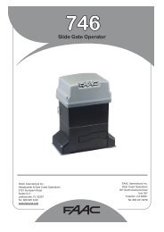
1. DESCRIPTION<br />
Model <strong>415</strong> L <strong>LS</strong> <strong>24V</strong> Swing Gate Operator<br />
The <strong>FAAC</strong> <strong>415</strong> is an automatic gate operator for swinging<br />
gate leafs. The <strong>415</strong> Operator is useful in residential applications<br />
and can accommodate gate leafs up to 14 ft long. The<br />
self-contained <strong>415</strong> Operator consists of an electric motor<br />
that drives a worm screw housed in an aluminum casing.<br />
The locking provided by the <strong>415</strong> Operator (in the fully<br />
opened and fully closed positions) is a service device rather<br />
than a security device.<br />
Also, for the protection and proper operation of the <strong>415</strong> Operator,<br />
each operator has built in limit switches, so positive<br />
stops are not needed.<br />
Pos. Description<br />
1 Operator<br />
2 Release Device<br />
3 Rod<br />
4 Front Bracket<br />
5 Rear Bracket<br />
6 Rear Fitting<br />
7 Rear Fitting Pin<br />
8 Terminal Board Cover<br />
Fig. 1<br />
Built-in security and anti-crushing measures of the <strong>415</strong><br />
Operator include built in reverse on contact and a torque<br />
adjustment that controls the force transmitted to the gate leaf<br />
through the <strong>415</strong> Operator.<br />
The Manual Release mechanism is a key accessed device<br />
that disengages (or engages) the cylinder on the <strong>415</strong> Operator.<br />
When the drive is disengaged, you can manually open<br />
and close the gate leaf by hand.<br />
Such manual operation of the gate is necessary during<br />
installation and useful during prolonged power failures. The<br />
torque of the <strong>415</strong> Operator is set using the Control Panel.<br />
Reversing devices (such as inductive loops and photocells)<br />
should be installed to provide non-contact reversing operation.<br />
The <strong>415</strong> Operator automated system was designed and built<br />
for controlling vehicle access. Avoid any other use what so<br />
ever.<br />
NOTES:<br />
• Use suitable conduit to lay electric cables.<br />
• To avoid any kind of interference, always use individual<br />
sheaths to separate low-voltage accessories and control<br />
cables from 115V~ power supply cables.<br />
2. DIMENSIONS<br />
6 <strong>FAAC</strong> Model <strong>415</strong> L <strong>LS</strong> <strong>24V</strong> Swing Gate Operator<br />
4¼<br />
* Measurements in Inches<br />
37<br />
5¾<br />
Fig. 2
3. TECHNICAL SPECIFICATIONS<br />
SPECIFICATION <strong>415</strong> L <strong>LS</strong> <strong>24V</strong><br />
Power Supply 24 VDC<br />
Power (W) 70<br />
Current (A) 3<br />
Thrust (lbf) 630<br />
Effective Stroke (inches) 15<br />
Rod Extension Speed (inches/sec) 0.5<br />
Max Leaf Length (feet) 15<br />
Cycle per hour at 68˚F (approx) 75<br />
Class or Operation Residential<br />
Ambient Operating Temperature<br />
Range (˚F)<br />
4. INSTALLATION<br />
Pos. Description Cables<br />
1 Operators 2 x AWG 14 (max 30’)<br />
AWG 12 (max 50’)<br />
AWG 10 (max 100’)<br />
1 Limit Switches 3 x AWG 20<br />
2 Control Unit 3 x AWG 14 (AC power)<br />
3 TX Photocells 4 x AWG 20<br />
4 RX Photocells 2 x AWG 20<br />
5 Key-operated Switch 2 x AWG 20<br />
6 Flashing Lamp 2 x AWG 14<br />
7 Receiver 3 x AWG 20<br />
8 Mechanical Stops -<br />
-4 to +131<br />
Operator Weight (lbs) 17.5<br />
Protection Class IP 54<br />
4.1 Electrical Set-up (Standard System)<br />
<strong>FAAC</strong> Model <strong>415</strong> L <strong>LS</strong> <strong>24V</strong> Swing Gate Operator<br />
Fig. 3<br />
4.2 Preliminary Checks<br />
The condition of the gate structure directly affects the reliability<br />
and safety of the automated system. Before installing the<br />
<strong>415</strong> Operator, prepare the gate for the operator by performing<br />
the following:<br />
• Make sure that the gate structure is solidly built. Add reinforcing<br />
crosspieces to the gate leaves if necessary.<br />
• Make sure that the gate moves smoothly on its hinges<br />
without excessive friction by swinging it opened and<br />
closed by hand. If necessary, lubricate all the gate’s<br />
moving parts.<br />
Positive stops are not needed with the <strong>415</strong> operator, the built<br />
limit switches can be used to limit the rod travel<br />
4.3 Installation Dimensions<br />
Determine the mounting position of the operator with<br />
reference to Fig. 4.<br />
Ensure that the distance between the open leaf and any<br />
obstacles (walls, fences etc.) is greater than the dimensions<br />
of the operator.<br />
Fig. 4<br />
MODEL <strong>415</strong> L <strong>LS</strong> <strong>24V</strong><br />
* Dimensions<br />
in Inches<br />
90° 110°<br />
A 7⅝ 6⅝<br />
B 7⅝ 6⅝<br />
D (1) 5 4⅜<br />
Z (2) 2¾ 2¾<br />
L 50¾ 50¾<br />
E (2) 1¾<br />
(1) max. dimension<br />
(2) min. dimension<br />
7
Guidelines for Determining Installation Dimensions<br />
• For 90° leaf openings: A+B=L<br />
• For leaf openings exceeding 90°: A+B
6. Turn the rod one half revolution clockwise (Fig. 9, Ref. 2).<br />
7. Assemble the front bracket as shown in Fig. 10.<br />
8. Fix the operator to the rear bracket by means of the supplied<br />
pins as shown in Fig. 11.<br />
Attention: allow the bracket to cool before fastening the<br />
operator to it.<br />
9. Close the leaf and, while keeping the operator perfectly<br />
horizontal, determine the fastening point of the front<br />
bracket (Fig.12).<br />
10. Temporarily fix the front bracket with two welding spots<br />
(Fig.12).<br />
Note: if the gate structure does not allow a fixed bracket<br />
fastening it is necessary to create a sturdy supporting<br />
base in the gate structure.<br />
11. Release the operator (see Section 6) and manually check<br />
that the gate moves regularly without friction or hindrances.<br />
Ensure that it opens completely and stops at the<br />
mechanical travel stops.<br />
<strong>FAAC</strong> Model <strong>415</strong> L <strong>LS</strong> <strong>24V</strong> Swing Gate Operator<br />
Fig. 9<br />
Fig. 10<br />
Fig. 11<br />
12. Perform the necessary corrective measures and repeat<br />
from Step 11.<br />
13. Temporarily release the operator from the front bracket<br />
and permenantly weld the bracket.<br />
If the leaf structure prevents the bracket from being welded,<br />
screw it to the leaf with adequate securing hardware.<br />
Note: Grease all fastening pins of the fittings.<br />
4.5. Wiring the Operator<br />
IMPORTANT : Use the supplied cable or a similar UL approved<br />
cable for outdoor use.<br />
A terminal block is available in the lower part of the operator<br />
to connect the motor and the limit switches<br />
Motor Wiring Instructions:<br />
1. Open one of the predrilled<br />
holes in the supplied<br />
cover (Fig.13).<br />
2. Fit the supplied cable<br />
gland.<br />
3. Connect the motor (refer<br />
to Fig.14 and accompanying<br />
table)<br />
Fig. 12<br />
Fig. 13<br />
9
Limit Switches wiring instructions:<br />
Limit switches are wired in the<br />
same terminal block where<br />
the motor wiring has been installed.<br />
Wire the limit switches<br />
as follows:<br />
1. Open the second predrilled<br />
hole in the cover,<br />
see Fig. 15.<br />
2. Fit the supplied cable<br />
gland, see Fig. 15.<br />
Figure 14 Table<br />
3. Insert the cable and connect<br />
it to the terminals,<br />
following the connections<br />
specified in Figure 16<br />
Table.<br />
<strong>415</strong> (24 VDC)<br />
POS. COLOR DESCRIPTION<br />
1 White Motor Lead 1<br />
- Not used -<br />
2 Brown Motor Lead 2<br />
Figure 16 Table<br />
Fig. 16<br />
POS. COLOR DESCRIPTION<br />
1 Blue Common<br />
2 Brown Closing Limit Switch (FCC)<br />
3 Black Opening Limit Switch (FCA)<br />
Fig. 14<br />
Fig. 15<br />
• Close and secure the cover with the four supplied screws<br />
(Fig. 17).<br />
4.6 Adjusting the Limit Switches<br />
Note: Limit switches are triggered during the first and the last<br />
1.25 inches of travel. Therefore, the operator should utilize<br />
the entire available length of travel during the opening phase.<br />
Shorter travels can limit or completely cancel the limit switch<br />
adjustment range.<br />
Limit switches adjustment is carried out as follows:<br />
Fig. 17<br />
1. Unscrew the upper fastening screw, Fig.18 Ref.A, and<br />
remove the cap, Fig.18 Ref.B.<br />
Fig. 18<br />
2. To adjust the closing limit switch FCC, turn the adjusting<br />
screw clockwise (Fig.19 Ref.A) to increase rod<br />
stroke and counter-clockwise to reduce it.<br />
3. To adjust the opening limit switch FCA, turn the adjusting<br />
screw counter-clockwise (Fig. 20 Ref. A) to increase<br />
rod stroke and clockwise to reduce it.<br />
4. Perform a pair of test cycles to check the correct position<br />
of the limit switch. If the limit switch needs additional<br />
adjustment, repeat the operation starting from<br />
Step 2.<br />
Fig. 19<br />
10 <strong>FAAC</strong> Model <strong>415</strong> L <strong>LS</strong> <strong>24V</strong> Swing Gate Operator
5. Reposition the cap (Fig. 18 Ref. B) and tighten the<br />
fastening screw (Fig. 18 Ref. A).<br />
4.7. Start-up<br />
ATTENTION: Cut power before performing any work on<br />
the system or operator.<br />
Carefully observe the GENERAL SAFETY RULES.<br />
Following the indications in Fig. 3, lay the proper cable<br />
conduits and make the electrical connections of the control<br />
board and chosen accessories.<br />
1. Power up the system and determine the status of<br />
the LEDs (as shown in the table of the control board<br />
instructions).<br />
2. Program the control board according to your needs by<br />
following the control board instructions.<br />
3. Test the system, carefully checking the operating efficiency<br />
of the motor and of all the accessories connected<br />
to it, paying special attention to the safety devices<br />
5. MANUAL OPERATION<br />
If the gate system needs to be moved manually due to lack<br />
of power or to an operator malfunction, proceed as follows:<br />
1. Cut power by means of the safety circuit breaker (even<br />
in the event of a power outage).<br />
2. Slide the protective cap, Fig. 21, Ref. 1.<br />
3. Insert the key and turn it 90°, Fig .21, Ref. 2.<br />
4. To release the operator, turn the control lever 180°<br />
in the direction indicated by the arrow on the release<br />
system, Fig.21, Ref. 3.<br />
5. Open and close the leaf manually.<br />
Fig. 21 Ref. 1<br />
<strong>FAAC</strong> Model <strong>415</strong> L <strong>LS</strong> <strong>24V</strong> Swing Gate Operator<br />
Fig. 20<br />
Fig. 21 Ref. 2<br />
Note: To keep the operator in manual operation, the control<br />
lever should be left in its current position (turned 180˚) and<br />
power should be cut to the system.<br />
Restoring Normal Operation<br />
To restore normal operating conditions, proceed as follows:<br />
1. Turn the release system’s control lever 180° in the opposite<br />
direction of the arrow.<br />
2. Turn the release key 90° and remove it.<br />
3. Close the protection cover.<br />
4. Power up the system and perform a complete cycle of<br />
movement to check that the automated system is correctly<br />
restored.<br />
6. MAINTENANCE<br />
7. REPAIRS<br />
Fig. 21 Ref. 3<br />
To ensure safety and trouble-free operation, an overall<br />
check of the system should be carried out every 6 months.<br />
For any repairs, contact an authorized <strong>FAAC</strong> repair center.<br />
11
8. <strong>415</strong> L <strong>LS</strong> PARTS DIAGRAM<br />
POS. P/N DESCRIPTION<br />
01 72200165 REAR MOUNTING BRACKET<br />
18 718367 SCREW DRIVE PIN WITH SEEGER<br />
02 72840065 REAR MOUNTING PLATE<br />
19 499399 LOCKING LOWER FLANGE<br />
03 718366 LONG PIN<br />
20 N/A 6.3X19mm SELF TAPPING SCREW<br />
04 7182075 SHORT PIN<br />
21 60202225 GEAR (piston)<br />
05<br />
06<br />
N/A<br />
7221115<br />
HEX NUT<br />
REAR FORK<br />
22 N/A<br />
PARTS 23 LIST 60202165<br />
4.8X13mm SELF TAPPING SCREW<br />
BUSHING<br />
07 716148 UPPER BODY<br />
24 60202215 GEAR (motor)<br />
08 428403 MANUAL RELEASE ASSEMBLY<br />
25 60202205 <strong>24V</strong> MOTOR<br />
Code 09 60202145 <strong>415</strong> L <strong>LS</strong> <strong>24V</strong> MANUAL RELEASE CAM<br />
Start 26Date 1/1/1900 709324 GASKET<br />
Description 10 60202155 ELECTRO-MECHANICAL<br />
MANUAL RELEASE LEVER<br />
End 27Date 1/1/9999 60202175 ELECTRIC CABLE COVER<br />
11 716151 AUTOMATION PROTECTIVE FOR RESIDENTIAL<br />
COVER<br />
28 Table <strong>415</strong> 716149 L <strong>LS</strong> 24vdcLOWER<br />
HALF BODY<br />
12<br />
Pos. Code<br />
13<br />
490108<br />
718354<br />
LIMIT SWITCH ASSEMBLY<br />
Qty. Q.ty Avaibility Description<br />
FRONT per PIN WITH SEEGER<br />
29<br />
31<br />
490106<br />
7120885<br />
<strong>415</strong> <strong>LS</strong> SKIN PACK<br />
LOCK KEY<br />
001 14 72200165N/A 1 4.2X13mm 1 SELF TAPPING Y SCREW 413/<strong>415</strong> REAR BRACKET<br />
002 15 72840065728271 1 FRONT 1MOUNTING Y BRACKET413/<strong>415</strong><br />
REAR BRACKET PLATE<br />
003 16 718366 711027 1 LIMIT SWITCH 1 ADJUSTERS Y COVER 413/<strong>415</strong> LONG PIN<br />
004 17 7182075 490104 1 CYLINDER 1 S SHORT PIN 400<br />
005 702202 1 1 N NUT EX. 8 5589 5S Z<br />
Page 1<br />
POS. P/N DESCRIPTION<br />
12 <strong>FAAC</strong> Model <strong>415</strong> L <strong>LS</strong> <strong>24V</strong> Swing Gate Operator
1. E024U CONTROL BOARD DESCRIPTION & CHARACTERISTICS<br />
Main power supply 115 V~ 60 Hz<br />
DL14 DL15 DL16 DL17 DL18<br />
SETTING<br />
Secondary power<br />
24 Vdc - 16 A max.<br />
supply<br />
(min. 20 Vdc. - max. 36 Vdc.)<br />
Power consumption stand-by = 4W max. = 400 W<br />
Max load per motor 7 A<br />
Accessory power<br />
supply<br />
24 Vdc - 500 mA<br />
Battery charge current 150 mA<br />
Operating temperature -4 °F.........+131 °F<br />
Protection fuses All self-resetting<br />
Main power fuse 6.3 A Timed<br />
Operating Logics E, A, S, EP, AP, SP, B, C<br />
Operating time out 10 min.<br />
Pause time Programmable (0 to 4 min)<br />
with trimmer<br />
Motor force, speed,<br />
obstacle sensitivity,<br />
closing delay<br />
Programmable with<br />
dedicated trimmer<br />
Connector inputs Power supply, Battery,<br />
Radio receiver, USB<br />
Terminal strip inputs Encoder, Open A, OpenB, Stop,<br />
Open safety fotocell, Closing safety<br />
fotocell, Limit switches<br />
Terminal strip outputs Lamp, Buzzer, Motors, Lock,<br />
Programmable OUT,<br />
accessory power supply<br />
Programming With trimmers, dipswitches<br />
and pushbutton<br />
J24<br />
DL19 DL20 DL21 DL22<br />
1.1 TECHNICAL SPECIFICATIONS 1.2 LAYOUT AND COMPONENTS<br />
RADIO Connector for the radio receiver<br />
BATTERY Connector for the backup battery<br />
J24 Jumper to disable battery charging<br />
(With the jumper present the battery<br />
is charged)<br />
POWER SUPPLY DC Power supply input<br />
TR1 to TR6 Programming Trimmers<br />
+24 LED DC power indicator<br />
SW1 - SETUP Pushbutton for automatic setup<br />
DS1 - DS2 Programming dipswitches<br />
LED ERROR Troubleshooting indicator<br />
USB A USB connection for software upgrade<br />
1.3 RADIO CONNECTION<br />
On the radio connector it’s possible to plug in receivers RP<br />
and RP2. With a single channel radio RP it will be possible to<br />
activate only the OPEN A input, with a dual channel radio RP2<br />
it will be possible to activate both OPEN A and OPEN B inputs.<br />
Plug in the radio board with the component side towards the<br />
internal part of the board.<br />
Make sure you insert or disconnect the board ONLY with the<br />
power off.<br />
+<br />
Fig. A1<br />
A2 E024U CONTROL BOARD
2. INPUT / OUTPUT DESCRIPTION<br />
A B STP CL OP<br />
OPEN FSW<br />
PIN LABEL FUNCTION<br />
2 EASY 2 EASY Input for bus 2easy accessories (encoder)<br />
1 OPEN A N.O. Contact for total opening command<br />
2 OPEN B /<br />
CLOSE<br />
OPEN B: N.O. Contact for opening of leaf 1 only<br />
(with only one leaf the opening stops at 50% of traveling)<br />
CLOSE (LOGIC B-C): N.O. Contact for closing command<br />
3 STOP N.C. Contact for stop command<br />
4 FSW CL N.C. Contact for closing safety<br />
5 FSW OP N.C. Contact for opening safety<br />
6 GND (-) 24 Vdc negative<br />
7 GND (-) 24 Vdc negative<br />
8 + 24 24 Vdc positive<br />
9 OUT (-) Programmable output (See: DS1 SW 11-12)<br />
10 FCA 1 Open limit switch Motor 1<br />
11 GND (-) 24 Vdc negative<br />
12 FCC 1 Close limit switch Motor 1<br />
13 FCA 2 Open limit switch Motor 2<br />
14 GND (-) 24 Vdc negative<br />
15 FCC2 Close limit switch Motor 2<br />
LAMP LAMP Audio alarm output (DS1 SW11=OFF)<br />
Output for flashing light <strong>24V</strong>dc 15W max (DS1 SW11=ON)<br />
LOCK LOCK Output for electrical lock, max 5A pulse (DS2 - SW 4=OFF) 12 Vac / <strong>24V</strong>dc<br />
Always ON (maglock): max 1 A (DS2 - SW 4=ON) 24 Vdc<br />
MOT1 MOT 1 Motor 1 output ( first moving motor )<br />
MOT2 MOT 2 Motor 2 output ( second moving motor )<br />
USB A USB Firmware upgrade input<br />
E024U CONTROL BOARD<br />
Fig. A2<br />
A3
3. PHOTOCEL<strong>LS</strong> CONNECTIONS<br />
How to connect Normally Open contacts.<br />
(Connect them in parallel)<br />
Fig. A3<br />
The E024U board allows the connection of several safety devices<br />
(for example photocells). With photocells you can activate the<br />
FAI<strong>LS</strong>AFE function, which, before each movement of the operator,<br />
tests each fotocells. In case the test fails the movement<br />
is inhibited. To activate this function set to ON the dip-switch N.<br />
11 and 12 of DS1, and connect the negative of the transmitter<br />
to the OUT pin (No.9).<br />
The photocells must be connected depending on which area<br />
they must protect. (See Fig. A5)<br />
Closing Safety D : These photocells protect the area covered<br />
by the gate during the closing movement. They have no effect<br />
during the opening movement.<br />
Opening Safety B-C : These photocells protect the area covered<br />
by the gate during the opening movement. They have no effect<br />
during the closing movement.<br />
Opening/Closing Safety A : These photocells protect the area<br />
covered by the gate both during the opening and the closing<br />
movements.<br />
3.1 CONNECTIONS TO NORMALLY CLOSE (N.C.) PHOTOCEL<strong>LS</strong><br />
FSW<br />
STP CL OP<br />
How to connect Normally Close contacts.<br />
(Connect them in series)<br />
Connection of a pair of closing photocells and a pair of opening/closing photocells<br />
RX= Photocell Receiver<br />
TX= Ptotocell Transmitter<br />
CL= Closing<br />
OP= Opening<br />
To use the FAIL-SAFE mode connect the negative power supply of the transmitters to OUT (pin 9), and set dipswitch<br />
11 and 12 to ON on DS1<br />
Fig. A6<br />
Fig. A4<br />
Fig. A5<br />
A4 E024U CONTROL BOARD
FSW<br />
STP CL OP<br />
Connection of two pairs of closing photocells<br />
Connection of a pair of closing photocells, a pair of opening photcells and a pair of opening/closing photocells<br />
FSW<br />
STP CL OP<br />
Other optional safety devices to connect in series<br />
To use the FAIL-SAFE mode connect the negative power supply of the transmitters to OUT (pin 9), and<br />
set dip-switch 11 and 12 to ON on DS1<br />
When using the FAIL-SAFE mode also the safety inputs not used (FSW CL , FSW OP) must be connected<br />
to OUT (pin No. 9)<br />
To use the FAIL-SAFE mode connect the negative power supply of the transmitters to OUT (pin 9),<br />
and set dip-switch 11 and 12 to ON on DS1<br />
E024U CONTROL BOARD<br />
RX= Photocell Receiver<br />
TX= Ptotocell Transmitter<br />
CL= Closing<br />
OP= Opening<br />
Fig. A7<br />
RX= Photocell Receiver<br />
TX= Ptotocell Transmitter<br />
CL= Closing<br />
OP= Opening<br />
Fig. A8<br />
A5
FSW<br />
STP CL OP<br />
FSW<br />
STP CL OP<br />
To use the FAIL-SAFE mode connect the negative power supply of the transmitters to OUT (pin 9), and set dipswitch<br />
11 and 12 to ON on DS1<br />
Connection of no safety or stop devices<br />
(NOT RECOMMENDED)<br />
FSW<br />
STP CL OP<br />
Connection of a pair of closing photocells and a pair of opening photocells<br />
Fig. A10<br />
Connection of a generic closing safety device and a generic<br />
open safety device<br />
Fig. A11<br />
Connection of one pair of opening photocells<br />
8<br />
FSW<br />
STP CL OP<br />
RX= Photocell Receiver<br />
TX= Ptotocell Transmitter<br />
CL= Closing<br />
OP= Opening<br />
Fig. A9<br />
Other optional safety devices to<br />
connect in series<br />
To use the FAIL-SAFE mode connect the negative<br />
power supply of the transmitters to OUT<br />
(pin 9), and set dip-switch 11 and 12 to ON on<br />
DS1<br />
When using the FAIL-SAFE mode also the<br />
safety inputs not used (FSW CL , FSW OP)<br />
must be connected to OUT (pin No. 9)<br />
Fig. A12<br />
A6 E024U CONTROL BOARD<br />
8
4. PROGRAMMING<br />
4.1 DIP SWITCH DS1 SETTINGS FOR OPERATING LOGIC<br />
OPERATING LOGIC<br />
DS 1: SW 1 - SW 2 - SW 3<br />
LOGIC<br />
E (default)<br />
Semiautomatic<br />
A<br />
Automatic<br />
S<br />
Security<br />
EP<br />
Semiautomatic<br />
step by step<br />
AP<br />
Automatic<br />
step by step<br />
SP<br />
Security<br />
step by step<br />
B<br />
Manned Pulsed<br />
C<br />
Manned Constant<br />
E024U CONTROL BOARD<br />
SW<br />
1<br />
SW<br />
2<br />
SW<br />
3<br />
PAUSE<br />
TIME<br />
OFF OFF OFF NO<br />
ON ON ON<br />
OFF OFF ON<br />
0 - 4<br />
min<br />
0-4<br />
min<br />
OFF ON OFF NO<br />
OFF ON ON<br />
ON OFF OFF<br />
0-4<br />
min<br />
0-4<br />
min<br />
ON OFF ON NO<br />
ON ON OFF NO<br />
DESCRIPTION<br />
One command opens, the next one closes. A command during<br />
opening stops the gate<br />
One command opens, waits for the pause time an then closes<br />
automatically<br />
One command opens, waits for the pause time and then closes<br />
automatically. If the closing safety is activated or another<br />
command is given during the pause time it closes<br />
One command opens, the next one closes. During the movement<br />
a command stops the gate<br />
One command opens, waits for the pause time and then closes<br />
automatically. A command during the pause time holds<br />
the gate open<br />
One command opens, waits for the pause time and then<br />
closes automatically. If the closing safety is activated during<br />
pause time the gate closes in 5 s. A command during pause<br />
time holds open the gate<br />
An open A command opens the gate, an open B command<br />
closes the gate<br />
Holding open A active opens the gate, holding Open B active<br />
closes the gate<br />
For more details on the operating logics please refer to Chapter 12 - Function Logics<br />
A7
4.2 ADJUSTING TRIMMERS<br />
TR1 – FORCE ADJUSTMENT MOTOR 1<br />
Turn clockwise to increase the opening and closing force<br />
TR 2 – FORCE ADJUSTEMENT MOTOR 2<br />
Turn clockwise to increase the opening and closing force<br />
TR 3 – SPEED ADJUSTMENT FOR MOTOR1 AND MOTOR 2<br />
Turn clockwise to increase the opening and closing speed<br />
TR 4 – SENSITIVITY ADJUSTEMENT FOR OBSTACLE DETECTION FOR MOTOR 1 AND MOTOR 2<br />
Turn clockwise to increase the sensitivity for obstacle detection.<br />
With this trimmer you can adjust the reaction time for the board to invert the motion of the gate in case of<br />
obstacle detection, or the complete stop in case the board is in the positive stop detection zone.<br />
If an obstacle is detected during the gate movement the board will invert the motor rotation until the gate goes<br />
back to the original starting position. If in the successive movement an obstacle is detected again the board<br />
will be put in alarm mode and won’t take any more commands until the STOP input is activated (Alarm Reset)<br />
or power is cycled<br />
TR 5 – PAUSE TIME ADJUSTMENT ( 0 - 4 min. )<br />
Turn clockwise to increase the pause time.<br />
30 sec<br />
0 sec<br />
E024U CONTROL BOARD<br />
1 min<br />
2 min<br />
3 min<br />
4 min<br />
TR6 - CLOSING DELAY OF LEAF 1 OVER LEAF 2 ADJUSTMENT ( 0 - 15 sec )<br />
Turn clockwise to increase the delay<br />
6<br />
Dip switches DS1: 1 to 3 need to<br />
be set for an operating mode with<br />
PAUSE time for this adjustment<br />
to have any effect<br />
A8
4.3 DIP SWITCH DS1 SETTINGS FOR BOARD SETUP<br />
BOARD SETUP<br />
DS 1: SW 4 to SW 12<br />
OPENING DELAY SW 4 The opening of leaf 2 is delayed after the opening of leaf 1. This is to avoid<br />
that the gate’s leafs interfere with each other during the initial part of the<br />
0 sec (default) OFF movement. In case there is only one leaf is has no effect.<br />
2 sec ON<br />
REVERSE AND LAST STROKE<br />
inactive (default)<br />
SW 5<br />
OFF<br />
If active, before opening, while the gate is closed, the motors thrust to<br />
close for 2 s to facilitate the release of the electric lock. At closing the<br />
motors are activated for a final stroke after slowdown to facilitate locking<br />
active ON of the electric lock.<br />
MAX THRUST AT STARTUP SW 6<br />
inactive (default) OFF<br />
active for 3 sec ON<br />
AUTOMATIC OPENING IN CASE OF<br />
POWER FAILURE<br />
inactive (default) OFF<br />
active ON<br />
CLOSING SAFETY LOGIC SW 8<br />
immediate reverse (default) OFF<br />
reverse when cleared ON<br />
PREFLASHING SW 9<br />
inactive (default) OFF<br />
active for 5 sec ON<br />
EXTRA SENSITIVITY TO<br />
OBSTACLE DETECTION<br />
With this fuction active the motors work at maximum force at startup<br />
(regardless of the force setting) during the initial phase of the movement.<br />
Useful for heavy leafs<br />
SW 7 If active and with the optional backup battery installed, the board will<br />
open the gate after one minute from the power failure and keep it open.<br />
Within the minute wait it’s always possible to open and close the gate<br />
with a command. If the logic used has a pause time the board will close<br />
the gate when the power comes back.<br />
SW 10<br />
inactive (default) OFF<br />
active ON<br />
With this function you can choose the behaviour of the closing safety. With<br />
SW8 OFF the gate movement will be reversed as soon as the safety is active,<br />
with SW8 ON the gate will stop when the safety is active and it will reverse<br />
only when the safety is deactivated again.<br />
This function activates the flashing lamp for 5s before the movement of<br />
the gate<br />
If active this function allows to have an immediate reverse in case the<br />
gate hits a rigid obstacle, while keeping the motor active in case of a<br />
gradual increment of resistance, like with wind pressure on the gate or<br />
increased friction<br />
ORANGE TERMINAL FUNCTION SW 11 If OFF after the second consecutive obstacle detection this output is<br />
activated until the STOP contact is open or the power is cycled<br />
if ON the output can be connected to a warning lamp.<br />
Audio Alarm (default) OFF NOTE: for UL325 compliance this switch must be left OFF<br />
Warning Lamp ON<br />
OUT FUNCTION (pin 9)<br />
max 100mA<br />
Lamp OFF<br />
Photocells FAIL SAFE active ON<br />
E024U CONTROL BOARD<br />
SW 12 if OFF: use pin 9 as power supply negative for a warning lamp. The<br />
lamp will be active during opening, pause and stop. Flashing during<br />
close, off when the gate is closed<br />
If ON: use pin 9 as power supply negative for the safety photocells.<br />
Before any movement the board will check for the presence of the<br />
safety photocells. If the test fails the gate will not move.<br />
A9
4.4 DIP SWITCH DS2 SETTINGS FOR OPERATOR TYPE AND LOCK MODE<br />
6<br />
IMPORTANT<br />
DS 2<br />
OPERATOR SELECTION<br />
OPERATOR TYPE SW 1 SW 2 SW 3<br />
S450H, S800H OFF OFF OFF<br />
S418 OFF OFF ON<br />
<strong>415</strong>, 390, 770 ON OFF OFF<br />
5. LED DIAGNOSTICS<br />
5<br />
3<br />
BUS<br />
SETTING<br />
7 DEVICE 8 9 10<br />
DL14 DL15 DL16 DL17 DL18<br />
2<br />
4<br />
DL 1 DL 2 DL 3 DL 4 DL 5<br />
1<br />
SETTING<br />
J24<br />
DL19 DL20 DL21 DL22<br />
DS2<br />
DS 2<br />
LOCK OUTPUT MODE<br />
OUTPUT MODE SW 4<br />
Active only for 3 sec. after an open impulse<br />
(from gate closed)<br />
J24<br />
+<br />
OFF<br />
Active always except 3 sec. before an opening ON<br />
A10 E024U CONTROL BOARD<br />
+
L<br />
E<br />
D<br />
DESCRIPTION<br />
1 LED BATTERY<br />
2<br />
3<br />
4<br />
5<br />
LED STATUS<br />
In BOLD the normal state with gate closed and working<br />
ON STEADY OFF BLINKING<br />
Board working on AC<br />
power<br />
A11<br />
Board working on<br />
battery power or ext<br />
supply<br />
LED +24 Main power present Main power OFF<br />
LED SET-UP<br />
Normal operation<br />
Battery charging<br />
SLOW BLINK<br />
(1 sec. ON - 1 sec. OFF)<br />
SET-UP needed<br />
FAST BLINK<br />
(0.5 sec. ON - 0.5 sec OFF)<br />
SET UP in in progress<br />
LED ERROR Board malfunction No errors Error conditions. See LED ERROR<br />
DISPLAY table<br />
LED BUS_MON Communication on<br />
Bus “2easy” OK<br />
6 LED USB<br />
7<br />
8<br />
9<br />
10<br />
RESERVED<br />
LED DL 14<br />
OPEN A INPUT (N.O.)<br />
LED DL 15<br />
OPEN B INPUT (N.O.)<br />
LED DL 16<br />
STOP INPUT (N.C.)<br />
LED DL 17<br />
FSW CL INPUT (N.C.)<br />
LED DL 18<br />
FSW OP INPUT (N.C.)<br />
LED DL 19 FCA1<br />
OPEN LIMIT SWITCH MO-<br />
TOR1 (N.C.)<br />
LED DL 20 FCC1<br />
CLOSE LIMIT SWITCH MO-<br />
TOR1 (N.C.)<br />
LED DL 21 FCA2<br />
OPEN LIMIT SWITCH MO-<br />
TOR2 (N.C.)<br />
LED DL 22 FCC2<br />
CLOSE LIMIT SWITCH MO-<br />
TOR2 (N.C.)<br />
E024U CONTROL BOARD<br />
Communication bus<br />
“2Easy” inactive. Verify<br />
the bus “2Easy” devices<br />
for shorts<br />
Software update done<br />
or USB key not present<br />
OPEN A active OPEN A not active<br />
OPEN B active OPEN B not active<br />
STOP non active STOP active or<br />
wiring error<br />
Closing safety<br />
devices clear<br />
Opening safety<br />
devices clear<br />
Closing safety devices<br />
triggered or wiring error<br />
Opening safety devices<br />
triggered or wiring error<br />
Limit switch<br />
OFF or not used Limit Switch activated<br />
Limit switch<br />
OFF or not used Limit Switch activated<br />
Limit switch<br />
OFF or not used Limit Switch activated<br />
Limit switch<br />
OFF or not used Limit Switch activated<br />
Bus 2Easy devices with the<br />
Same address. Verify dip switch<br />
Setting on photocells or<br />
Encoder LEDs<br />
USB key inserted and software<br />
Update in progress<br />
(DON’T Remove the USB key)<br />
A11
NUMBER OF<br />
FLASHES<br />
After powering up the board for the first time or when the board<br />
will need it the setup LED will blink at a slow frequency to indicate<br />
that the setup procedure to learn the running times is needed.<br />
The setup can be redone at any time by pressing and holding<br />
the setup button as indicated below.<br />
After the setup first movement, if the leafs are opening instead<br />
of closing you need to reverse the wires going to the motor that<br />
moves in the wrong direction<br />
WARNING: If the time learning setup is done automatically then<br />
the slow down points are set by the board on his own<br />
Move the leafs to the mid position<br />
Very important for a good result<br />
1. Press and hold the SETUP button until the SETUP LED<br />
lights up, wait about 3 sec. until it turns off and then release<br />
it immediately. NOTE: If you wait too long to release it the<br />
manual set-up will start. The LED will blink during the setup<br />
procedure<br />
2. Leaf 2 (if present) starts to move slowly in closing direction,<br />
stopping when it reaches the mechanical stop or FCC2.<br />
3. Leaf 1 begins to move slowly in closing direction, stopping<br />
when it reaches the mechanical stop, or FCC1.<br />
4. Leaf 1 starts to move slowly in opening direction, followed<br />
by leaf 2 (if present) still slowly.<br />
5. When they both reach the open mechanical stop or FCA1 and<br />
FCA2 they stop and reverse, leaf 2 (if present) automatically<br />
starts closing at full speed followed by leaf 1.<br />
LED ERROR DISPLAY<br />
ERROR CONDITION SOLUTION<br />
1 OBSTACLE DETECTION Remove the obstacle<br />
2 BOARD IN SLEEP MODE<br />
(Slow blinking means that the automatic open<br />
in case of power failure function is active)<br />
Verify the presence of AC power<br />
3 MOTOR 1 FAILURE Replace motor 1<br />
4 MOTOR 2 FAILURE Replace motor 2<br />
5<br />
ENCODER on motor 1 or motor 2 broken or<br />
wiring error<br />
Verify the encoder wiring and LED status. If they are correct replace<br />
the encoder<br />
6 FAIL SAFE FAILED Verify the photocells wiring and alignement<br />
7 BOARD THERMAL PROTECTION ACTIVE Turn off the board and wait until the components cool down<br />
8<br />
The diagnostic LED shows only one error condition at a time, with the priority of the below table. In case there is more<br />
than one error once one is eliminated the LED will show the next<br />
MAX RUN TIME REACHED<br />
WITHOUT FINDING THE<br />
POSITIVE STOP (10 min. )<br />
6. TIME LEARNING (SET-UP)<br />
6.1 AUTOMATIC TIME LEARNING<br />
- Verify that the operator manual release is not engaged<br />
- Verify that the board recognizes the mechanical stop, in<br />
case redo the setup procedure<br />
6. When they reach the close mechanical stop or FCC1 and<br />
FCC2 both leafs stop and leaf 1 restarts automatically opening<br />
at full speed followed by leaf 2 (if present).<br />
7. If you selected an automatic logic the board will wait for the<br />
pause time and then closes the gate automatically. Otherwise<br />
you have to give an OPEN command to close the gate.<br />
6.2 MANUAL TIME LEARNING<br />
WARNING: If the manual time learning setup is done then<br />
the slow down points must be set by the installer during the<br />
procedure<br />
Move the leafs to the mid position<br />
Very important for a good result<br />
1. Press and hold the SETUP button until the SETUP LED<br />
lights up, keep it pressed for about 3 sec. until it turns off and<br />
keep it pressed more until the leaf 2 (if present) starts moving<br />
slowly. The LED will blink during the setup procedure<br />
2. Leaf 2 will move in closing direction until it reaches the<br />
mechanical stop or FCC2<br />
3. Leaf 1 starts moving slowly until it reaches the mechanical<br />
stop or FCC1<br />
4. Leaf 1 starts moving in opening direction at the set speed<br />
(trimmer speed).<br />
5. At the point where you want the slowdown to start give an<br />
OPEN A command with the push button or the remote that<br />
is already stored in memory. Leaf 1 starts to slow down<br />
and stops when it reaches the mechanical stop or FCA1.<br />
6. Leaf 2 starts moving in opening direction at the set speed<br />
(trimmer speed)<br />
A12 E024U CONTROL BOARD
7. At the point where you want the slowdown to start give an<br />
OPEN A command with the push button or the remote that<br />
is already stored in memory. Leaf 2 starts to slow down and<br />
stops when it reaches the mechanical stop or FCA2.<br />
8. Leaf 2 starts to close at the set speed (trimmer speed).<br />
9. At the point where you want the slowdown to start give an<br />
OPEN A command with the push button or the remote that<br />
is already stored in memory. The leaf 2 starts to slow down<br />
and stops when it reaches the mechanical stop or FCC2.<br />
10. Leaf 1 starts to close at the set speed (trimmer speed).<br />
11. At the point where you want the slowdown to start give an<br />
OPEN A command with the push button or the remote that<br />
is already stored in memory. Leaf 1 starts to slow down and<br />
stops when it reaches the mechanical stop or FCC1.<br />
12. The manual time learning procedure is complete.<br />
6.3 OBSTACLE DETECTION FUNCTION<br />
The obstacle detection function is achieved by controlling the<br />
current absorption and / or through the encoder connected to<br />
the motors.<br />
If the gate encounters an obstacle during the movement of<br />
opening or closing, the obstacle detection function is activated<br />
and the operator reverses the direction of the gate.<br />
In case of a second consecutive obstacle the operator stops<br />
the gate right away and any further command is inhibited. To<br />
re-enable the automation, you must remove power or open the<br />
STOP contact input. Until this “reset” the Audio Alarm output<br />
will be active.<br />
7. ENCLOSURE<br />
The E024U board is supplied on a panel that fits in a 16x14”<br />
enclosure.<br />
15 15/32”<br />
E024U CONTROL BOARD<br />
6 7/32”<br />
17 15/32”<br />
Power outlet<br />
and switch<br />
DIN rail<br />
Batteries<br />
AC connection<br />
Power Supply<br />
E24U board<br />
Pushbutton<br />
On the back panel are installed the control board, the power<br />
supply and additional accessories.<br />
8. POWER CONNECTION<br />
AC POWER GUIDELINES:<br />
THE E024U control board and power supply uses a single<br />
phase AC power line to operate, charge the batteries, and power<br />
gate accessories. Use the following guidelines when installing<br />
the AC power:<br />
1. Check the local wiring codes in all cases and follow all local<br />
building codes. Wiring and hookup should be performed by a<br />
qualified electrician/installer only.<br />
2. AC power should be supplied from a circuit breaker panel and<br />
must have its own dedicated circuit breaker. This supply must<br />
include a green ground conductor.<br />
3. Use copper conductor wires with liquid tight flexible conduit<br />
UL listed for electric cable protection<br />
14 AWG, 600V, 80°C<br />
Terminal Block max Torque 2.1 Nm<br />
4. Properly ground the gate operator to minimize or prevent<br />
damage from power surges and/or lightning. Use a grounding<br />
rod if necessary. A surge suppressor is recommended for additional<br />
protection.<br />
A13
AC POWER CONNECTION<br />
To connect AC power to the controller:<br />
1. Turn the circuit breaker for the AC gate operator power OFF<br />
before connecting the AC input wires.<br />
2. Turn OFF the Power Switch located on the left side of enclosure<br />
before connecting the AC input wires.<br />
3. Connect the AC input wires to the AC terminal located on the<br />
top left of the control box. See diagram below.<br />
4. Batteries must be installed after the AC power is on. See<br />
Battery Power Connection.<br />
8.1 POWER SUPPLY<br />
115V 60Hz 6.3A<br />
The E024U board is powered by a high efficiency switching power<br />
supply that takes 115V in input and provides 36VDC to power the<br />
board. On the power supply board there is the only repleaceble<br />
fuse: 6.3A timed<br />
FUSE<br />
The E024U board allows the connection of a <strong>24V</strong> backup battery<br />
to provide power to operate the gate during blackouts. For<br />
more details about how the boards handles the loss of main<br />
power and how to configure its behaviour please see par 4.3<br />
and DS1 switch 7.<br />
To connect the battery use the provided cable and plug it on the<br />
BATTERY connector on the board. Plug the other end of the<br />
cable to the batteries, red wire to +24 and black wire to GND.<br />
SETTING<br />
9. BACKUP BATTERY<br />
DL 1 DL 2 DL 3 DL 4 DL 5<br />
SETTING<br />
9.1 DISABLE THE BATTERY CHARGER<br />
To disable the battery charger unplug jumper J24<br />
J24<br />
J24 PRESENT = BATTERY CHARGING ACTIVE<br />
J24 NOT PRESENT = BATTERY CHARGING NOT ACTIVE<br />
A14 E024U CONTROL BOARD<br />
DL 1 DL 2 DL 3 DL 4 DL 5<br />
SETTING<br />
J24<br />
J24<br />
+<br />
+
10. FIRMWARE UPGRADE<br />
The E024U board keeps the operating firmware in a field programmable<br />
memory, it can be easily upgraded through the on<br />
board USB port<br />
11. FUNCTION LOGICS<br />
LOGIC “E” PU<strong>LS</strong>ES<br />
SYSTEM STATUS OPEN A OPEN B CLOSE STOP FSW OP FSW CL FSW CL/OP<br />
CLOSED opens the leaves opens leaf 1 no effect<br />
OPENING<br />
OPEN<br />
CLOSING<br />
stops operation<br />
(1)<br />
recloses leaves<br />
immediately (1)<br />
reopens leaves<br />
immediately<br />
stops operation<br />
recloses leaves<br />
immediately<br />
reopens leaves<br />
immediately<br />
recloses<br />
leaves<br />
immediately<br />
recloses<br />
leaves<br />
immediately<br />
BLOCKED closes leaves closes leaves closes leaves<br />
no effect<br />
(OPEN disabled)<br />
stops operation<br />
no effect<br />
(OPEN/CLOSE<br />
disabled)<br />
no effect<br />
(OPEN disabled)<br />
immediately<br />
reverses at<br />
closing<br />
no effect<br />
no effect<br />
no effect<br />
no effect<br />
(OPEN disabled)<br />
stops and opens<br />
at release (OPEN<br />
stops - saves<br />
CLOSE)<br />
no effect<br />
no effect<br />
(CLOSE disabled)<br />
(OPEN/CLOSE<br />
disabled)<br />
stops and opens<br />
at release (OPEN<br />
stops - saves<br />
CLOSE)<br />
no effect stops operation no effect reverses at opening<br />
no effect<br />
(OPEN/CLOSE<br />
disabled)<br />
no effect<br />
(OPEN disabled)<br />
(1) if the cycle began with OPEN-B (leaf 1), both leaves are activated at opening<br />
LOGIC “A” PU<strong>LS</strong>ES<br />
no effect<br />
(CLOSE disabled)<br />
no effect<br />
(OPEN stops -<br />
saves CLOSE)<br />
SYSTEM STATUS OPEN A OPEN B CLOSE STOP FSW OP FSW CL FSW CL/OP<br />
CLOSED<br />
opens and closes<br />
after pause time<br />
opens leaf 1 and<br />
closes after pause<br />
time<br />
OPENING no effect (1) no effect<br />
OPEN IN<br />
PAUSE<br />
CLOSING<br />
reloads<br />
pause time (1)<br />
reopens leaves<br />
immediately<br />
DL 1 DL 2 DL 3 DL 4 DL 5<br />
reloads<br />
pause time of<br />
released leaf<br />
reopens leaves<br />
immediately<br />
SETTING<br />
no effect<br />
recloses leaves<br />
immediately<br />
recloses leaves<br />
immediately<br />
BLOCKED closes leaves closes leaves closes leaves<br />
For the upgrade you need a USB Flash Drive, where you have<br />
to copy the file supplied by <strong>FAAC</strong>. Then follow these steps:<br />
1. Disconnect the batteries if they are present.<br />
2. Turn the AC power off and insert the Flash Drive into the<br />
USB A input on the board<br />
3. Turn the AC power back on. The USB2 LED will start to flash<br />
to confirm the beginning of the software update. (WAR-<br />
NING: DON’T TURN THE POWER OFF OR REMOVE<br />
THE FLASH DRIVE UNTIL THE USB2 LED TURNS OFF.<br />
4. Wait until the USB 2 LED turns off<br />
5. Remove the USB Flash drive.<br />
6. Cycle power, reconnect the batteries if needed and execute<br />
a new SETUP procedure (See chapter 6)<br />
WARNING: Only upgrade the firmware with the proper file<br />
supplied by <strong>FAAC</strong>. otherwise the board could be damaged<br />
no effect<br />
(OPEN disabled)<br />
stops operation<br />
no effect<br />
(OPEN disabled)<br />
reverses at<br />
closing<br />
stops operation no effect<br />
no effect stops operation no effect<br />
no effect<br />
(OPEN/CLOSE<br />
disabled)<br />
no effect<br />
(OPEN disabled)<br />
(1) if the cycle began with OPEN-B (leaf 1), both leaves are activated at opening<br />
no effect<br />
no effect<br />
recharges<br />
pause time<br />
(CLOSE disabled)<br />
reverses at<br />
opening<br />
no effect<br />
(CLOSE disabled)<br />
no effect<br />
(OPEN disabled)<br />
stops and<br />
opens at<br />
release (saves<br />
CLOSE)<br />
recharges<br />
pause time<br />
(CLOSE disabled)<br />
stops and<br />
opens at<br />
release (saves<br />
CLOSE)<br />
no effect<br />
(OPEN/CLOSE<br />
disabled)<br />
A15 E024U CONTROL BOARD
LOGIC “S” PU<strong>LS</strong>ES<br />
SYSTEM STATUS OPEN A OPEN B CLOSE STOP FSW OP FSW CL FSW CL/OP<br />
CLOSED<br />
LOGIC “EP” PU<strong>LS</strong>ES<br />
SYSTEM STATUS OPEN A OPEN B CLOSE STOP FSW OP FSW CL FSW CL/OP<br />
CLOSED opens the leaves opens leaf 1 no effect<br />
OPENING stops operation (1) stops operation<br />
OPEN<br />
recloses leaves<br />
immediately (1)<br />
recloses leaves<br />
immediately<br />
recloses<br />
leaves<br />
immediately<br />
recloses<br />
leaves<br />
immediately<br />
no effect no effect<br />
(OPEN disabled) (OPEN disabled)<br />
stops operation<br />
no effect<br />
(OPEN/CLOSE<br />
disabled)<br />
immediately<br />
reverses at<br />
closure<br />
no effect<br />
CLOSING stops operation stops operation no effect stops operation no effect<br />
BLOCKED<br />
restarts moving in restarts moving in<br />
opposite direction. opposite direction.<br />
Always closes Always closes<br />
after STOP after STOP<br />
closes leaves<br />
no effect<br />
(OPEN/CLOSE<br />
disabled)<br />
LOGIC “AP” PU<strong>LS</strong>ES<br />
no effect<br />
(OPEN disabled)<br />
no effect<br />
no effect<br />
no effect<br />
(CLOSE disabled)<br />
reverses at<br />
opening<br />
no effect<br />
(CLOSE disabled)<br />
no effect<br />
(OPEN disabled)<br />
stops and opens<br />
at release<br />
(OPEN stops -<br />
saves CLOSE)<br />
no effect<br />
(OPEN/CLOSE<br />
disabled)<br />
stops and opens<br />
at release<br />
(OPEN stops -<br />
saves CLOSE)<br />
no effect<br />
(OPEN stops -<br />
saves CLOSE)<br />
SYSTEM STATUS OPEN A OPEN B CLOSE STOP FSW OP FSW CL FSW CL/OP<br />
CLOSED<br />
OPENING<br />
OPEN IN PAUSE<br />
CLOSING<br />
opens and closes<br />
after pause time<br />
opens and closes<br />
after pause time<br />
stops operation<br />
(1)<br />
stops operation<br />
(1)<br />
reopens leaves<br />
immediately<br />
opens released<br />
leaf and closes<br />
after pause time<br />
OPENING no effect (1) no effect<br />
OPEN IN<br />
PAUSE<br />
CLOSING<br />
recloses leaves<br />
immediately (1)<br />
reopens leaves<br />
immediately<br />
recloses leaves<br />
immediately<br />
reopens leaves<br />
immediately<br />
opens leaf 1 and<br />
closes after pause<br />
time<br />
stops operation<br />
stops operation<br />
reopens leaves<br />
immediately<br />
no effect<br />
recloses leaves<br />
immediately<br />
recloses leaves<br />
immediately<br />
BLOCKED closes leaves closes leaves closes leaves<br />
no effect<br />
recloses<br />
leaves<br />
immediately<br />
recloses<br />
leaves<br />
immediately<br />
BLOCKED closes leaves closes leaves closes leaves<br />
E024U CONTROL BOARD<br />
no effect<br />
(OPEN disabled)<br />
stops operation<br />
(1) if the cycle began with OPEN-B (leaf 1), both leaves are activated at opening<br />
no effect<br />
(OPEN disabled)<br />
stops operation<br />
no effect<br />
(OPEN disabled)<br />
reverses at<br />
closing (saves<br />
OPEN)<br />
stops operation no effect<br />
no effect stops operation no effect<br />
no effect<br />
(OPEN/CLOSE<br />
disabled)<br />
no effect<br />
(OPEN disabled)<br />
reverses at<br />
closure<br />
stops operation no effect<br />
no effect stops operation no effect<br />
no effect<br />
(OPEN/CLOSE<br />
disabled)<br />
no effect<br />
(OPEN disabled)<br />
no effect<br />
(OPEN disabled)<br />
no effect<br />
continues<br />
to open and<br />
recloses<br />
immediately<br />
stops and, at<br />
release, closes<br />
reverses at opening<br />
(see DS1-SW8)<br />
and closes immediately<br />
at end<br />
no effect<br />
(CLOSE disabled)<br />
(1) if the cycle began with OPEN-B (leaf 1), both leaves are activated at opening<br />
no effect<br />
no effect<br />
recharges<br />
pause time<br />
(CLOSE disabled)<br />
reverses at<br />
opening (see<br />
DS1-SW8)<br />
no effect<br />
(CLOSE disabled)<br />
(1) if the cycle began with OPEN-B (leaf 1), both leaves are activated at opening<br />
no effect<br />
(OPEN disabled)<br />
stops and opens<br />
at release<br />
(saves CLOSE)<br />
stops and, at<br />
release, closes<br />
stops and opens<br />
after release and<br />
closes immediately<br />
at end<br />
no effect<br />
(OPEN/CLOSE<br />
disabled)<br />
no effect<br />
(OPEN disabled)<br />
stops and opens<br />
at release<br />
(OPEN stops -<br />
saves CLOSE)<br />
recharges<br />
pause time<br />
(CLOSE disabled)<br />
stops and opens<br />
at release<br />
(OPEN stops -<br />
saves CLOSE)<br />
no effect<br />
(OPEN/CLOSE<br />
disabled)<br />
A16
LOGIC “SP” PU<strong>LS</strong>ES<br />
SYSTEM STATUS OPEN A OPEN B CLOSE STOP FSW OP FSW CL FSW CL/OP<br />
CLOSED<br />
OPENING<br />
OPEN IN PAUSE<br />
opens and closes<br />
after pause<br />
time<br />
stops operation<br />
(1)<br />
opens leaf 1 and<br />
closes after pause<br />
time<br />
stops operation<br />
recloses<br />
leaves<br />
recloses leaves<br />
immediately (1)<br />
immediately<br />
no effect<br />
recloses<br />
leaves<br />
immediately<br />
recloses<br />
leaves<br />
immediately<br />
LOGIC “B” PU<strong>LS</strong>ES<br />
SYSTEM STATUS OPEN A OPEN B CLOSE STOP FSW OP FSW CL FSW CL/OP<br />
CLOSED opens the leaves no effect no effect<br />
no effect<br />
(OPEN disabled)<br />
OPENING no effect closes leaves closes leaves stops operation<br />
OPEN no effect closes leaves closes leaves<br />
no effect<br />
(OPEN/CLOSE<br />
disabled)<br />
no effect<br />
(OPEN disabled)<br />
reverses at<br />
closure<br />
no effect<br />
CLOSING opens the leaves no effect no effect stops operation no effect<br />
BLOCKED opens the leaves closes leaves closes leaves<br />
no effect<br />
(OPEN/CLOSE<br />
disabled)<br />
no effect<br />
(OPEN disabled)<br />
LOGIC “C” CONTINUOS COMMANDS PU<strong>LS</strong>ES<br />
no effect<br />
no effect<br />
no effect<br />
(CLOSE disabled)<br />
reverses at<br />
opening<br />
no effect<br />
(CLOSE disabled)<br />
no effect<br />
(OPEN disabled)<br />
stops and, at<br />
release, closes<br />
(saves<br />
OPEN/CLOSE)<br />
no effect<br />
(OPEN/CLO-<br />
SE disabled)<br />
stops and<br />
opens at<br />
release<br />
(saves<br />
OPEN/CLOSE)<br />
no effect<br />
(OPEN/CLO-<br />
SE disabled)<br />
SYSTEM STATUS OPEN A OPEN B CLOSE STOP FSW OP FSW CL FSW CL/OP<br />
CLOSED opens the leaves no effect no effect<br />
no effect<br />
(OPEN disabled)<br />
OPENING no effect closes leaves closes leaves stops operation<br />
OPEN no effect closes leaves closes leaves<br />
no effect<br />
(OPEN/CLOSE<br />
disabled)<br />
no effect<br />
(OPEN disabled)<br />
reverses at<br />
closure<br />
no effect<br />
CLOSING opens the leaves no effect no effect stops operation no effect<br />
BLOCKED opens the leaves closes leaves closes leaves<br />
no effect<br />
(OPEN disabled)<br />
stops operation<br />
no effect<br />
(OPEN/CLOSE<br />
disabled)<br />
no effect<br />
(OPEN disabled)<br />
reverses at<br />
closure<br />
stops operation no effect<br />
no effect<br />
(OPEN disabled)<br />
no effect<br />
continues to open<br />
and recloses<br />
immediately<br />
stops and, at<br />
release, closes<br />
CLOSING stops operation stops operation no effect stops operation no effect reverses at opening<br />
BLOCKED<br />
restarts moving<br />
in opposite<br />
direction. Always<br />
closes after<br />
STOP<br />
restarts moving in<br />
opposite direction.<br />
Always closes<br />
after STOP<br />
recloses<br />
leaves<br />
immediately<br />
no effect<br />
(OPEN/CLOSE<br />
disabled)<br />
no effect<br />
(OPEN disabled)<br />
(1) if the cycle began with OPEN-B (leaf 1), both leaves are activated at opening<br />
no effect<br />
no effect<br />
no effect<br />
(CLOSE disabled)<br />
reverses at<br />
opening<br />
no effect<br />
(CLOSE disabled)<br />
no effect<br />
(OPEN disabled)<br />
stops and opens<br />
after release and<br />
closes immediately<br />
at end (OPEN stops<br />
- saves CLOSE)<br />
stops and, at<br />
release, closes<br />
stops and<br />
opens at<br />
release (saves<br />
CLOSE)<br />
no effect<br />
no effect<br />
(CLOSE disabled)<br />
(OPEN/CLOSE<br />
disabled)<br />
no effect<br />
(OPEN disabled)<br />
stops and, at<br />
release, closes<br />
(saves<br />
OPEN/CLOSE)<br />
no effect<br />
(OPEN/CLO-<br />
SE disabled)<br />
stops and<br />
opens at<br />
release<br />
(saves<br />
OPEN/CLOSE)<br />
no effect<br />
(OPEN/CLO-<br />
SE disabled)<br />
A17 E024U CONTROL BOARD
LIMITED WARRANTY<br />
To the original purchaser only:<br />
<strong>FAAC</strong> International, Inc., warrants, for twentyfour<br />
(24) months from the date of invoice, the<br />
gate operator systems and other related systems<br />
and equipment manufactured by <strong>FAAC</strong> S.p.A.<br />
and distributed by <strong>FAAC</strong> International, Inc., to be<br />
free from defects in material and workmanship<br />
under normal use and service for which it was<br />
intended provided it has been properly installed<br />
and operated.<br />
<strong>FAAC</strong> International, Inc.’s obligations under this<br />
warranty shall be limited to the repair or exchange<br />
of any part of parts manufactured by <strong>FAAC</strong><br />
S.p.A. and distributed by <strong>FAAC</strong> International, Inc.<br />
Defective products must be returned to <strong>FAAC</strong><br />
International, Inc., freight prepaid by purchaser,<br />
within the warranty period. Items returned will<br />
be repaired or replaced, at <strong>FAAC</strong> International,<br />
Inc.’s option, upon an examination of the product<br />
by <strong>FAAC</strong> International, Inc., which discloses, to<br />
the satisfaction of <strong>FAAC</strong> International, Inc., that<br />
the item is defective. <strong>FAAC</strong> International, Inc.<br />
will return the warranted item freight prepaid.<br />
The products manufactured by <strong>FAAC</strong> S.p.A. and<br />
distributed by <strong>FAAC</strong> International, Inc., are not<br />
warranted to meet the specific requirements,<br />
if any, of safety codes of any particular state,<br />
municipality, or other jurisdiction, and neither<br />
<strong>FAAC</strong> S.p.A. or <strong>FAAC</strong> International, Inc., assume<br />
any risk or liability whatsoever resulting from<br />
the use thereof, whether used singly or in<br />
combination with other machines or apparatus.<br />
Any products and parts not manufactured<br />
by <strong>FAAC</strong> S.p.A. and distributed by <strong>FAAC</strong><br />
International, Inc., will carry only the warranty,<br />
if any, of the manufacturer. This warranty shall<br />
not apply to any products or parts thereof which<br />
have been repaired or altered, without <strong>FAAC</strong><br />
International, Inc.’s written consent, outside of<br />
<strong>FAAC</strong> International, Inc.’s workshop, or altered<br />
in any way so as, in the judgment of <strong>FAAC</strong><br />
International, Inc., to affect adversely the stability<br />
or reliability of the product(s) or has been subject<br />
to misuse, negligence, or accident, or has<br />
not been operated in accordance with <strong>FAAC</strong><br />
International, Inc.’s or <strong>FAAC</strong> S.p.A.’s instructions<br />
or has been operated under conditions more<br />
severe than, or otherwise exceeding, those set<br />
forth in the specifications for such product(s).<br />
Neither <strong>FAAC</strong> S.p.A. nor <strong>FAAC</strong> International, Inc.,<br />
shall be liable for any loss or damage whatsoever<br />
resulting, directly or indirectly, from the use or<br />
loss of use of the product(s). Without limiting the<br />
foregoing, this exclusion from liability embraces a<br />
E024U CONTROL BOARD<br />
purchaser’s expenses for downtime or for making<br />
up downtime, damages for which the purchaser<br />
may be liable to other persons, damages to<br />
property, and injury to or death of any persons.<br />
<strong>FAAC</strong> S.p.A. or <strong>FAAC</strong> International, Inc., neither<br />
assumes nor authorizes any person to assume<br />
for them any other liability in connection with<br />
the sale or use of the products of <strong>FAAC</strong> S.p.A.<br />
or <strong>FAAC</strong> International, Inc. The warranty herein<br />
above set forth shall not be deemed to cover<br />
maintenance parts, including, but not limited to,<br />
hydraulic oil, filters, or the like. No agreement to<br />
replace or repair shall constitute an admission by<br />
<strong>FAAC</strong> S.p.A. or <strong>FAAC</strong> International, Inc., of any<br />
legal responsibility to effect such replacement,<br />
to make such repair, or otherwise. This limited<br />
warranty extends only to wholesale customers<br />
who buy directly through <strong>FAAC</strong> International,<br />
Inc.’s normal distribution channels. <strong>FAAC</strong><br />
International, Inc., does not warrant its products<br />
to end consumers.<br />
Consumers must inquire from their selling dealer<br />
as to the nature and extent of that dealer’s<br />
warranty, if any. This warranty is expressly in<br />
lieu of all other warranties expressed or implied<br />
including the warranties of merchantability and<br />
fitness for use. This warranty shall not apply to<br />
products or any part thereof which have been<br />
subject to accident, negligence, alteration, abuse,<br />
or misuse or if damage was due to improper<br />
installation or use of improper power source, or<br />
if damage was caused by fire, flood, lightning,<br />
electrical power surge, explosion, wind storm,<br />
hail, aircraft or vehicles, vandalism, riot or civil<br />
commotion, or acts of God.<br />
A18