Grasso - GEA Refrigeration Technologies
Grasso - GEA Refrigeration Technologies
Grasso - GEA Refrigeration Technologies

You also want an ePaper? Increase the reach of your titles
YUMPU automatically turns print PDFs into web optimized ePapers that Google loves.
<strong>Refrigeration</strong> Division<br />
<strong>Grasso</strong><br />
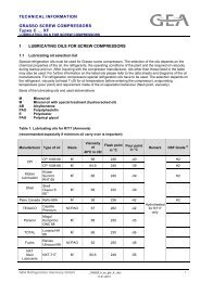
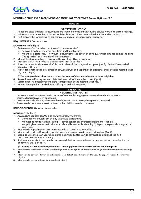
MOUNTING COUPLING GUARD/ MONTAGE KOPPELING BESCHERMER <strong>Grasso</strong> 12/<strong>Grasso</strong> 12E<br />
ENGLISH<br />
00.87.547 v001.9810<br />
SAFETY INSTRUCTIONS<br />
1. All federal state and local safety regulations should be complied with during service work in or on the package.<br />
2. This service task should be carried out only by those who have been trained and authorised to do so.<br />
3. First prepare the compressor as per compressor manual, delivered with compressor<br />
REQUIREMENTS: Common tools<br />
MOUNTING (refer fig 1)<br />
1. Before mounting the drive coupling onto compressor shaft;<br />
Remove 4 bolts (every other one) from shaft seal housing.<br />
Mount steel plate (fig. 1, however , excluding meshed cover) of drive guard with distance bushes and bolts<br />
(fig. 2) to shaft seal housing of the compressor.<br />
2. Mount the drive coupling according to the coupling fitting instructions.<br />
3. Mount the lower half of the meshed cover to steel plate (fig. 1)<br />
4. Form the recess for the motor shaft in the 2 halves of the octagonal end plate (see fig. 5) (R=½*motor shaft<br />
diameter + 10 mm)<br />
5. Adjust for length in the axial direction between lower and upper half of octagonal end plate and meshed cover<br />
(fig. 3 and fig. 4)<br />
The octagonal end plate must overlap the joints of the meshed cover to ensure rigidity.<br />
6. Secure lower half octagonal end plate to lower half of the meshed cover (fig. 4).<br />
7. Secure upper half octagonal end plate to upper half of the meshed cover (fig. 4).<br />
8. Mount the upper half on the lower half (fig. 5) and bolt together.<br />
NEDERLANDS<br />
VEILIGHEIDSINSTRUCTIES<br />
1. Gedurende servicewerkzaamheden in, aan of rondom het aggregaat moeten de nationale en lokale<br />
veiligheidsnormen worden opgevolgd.<br />
2. Deze service activiteit mag alleen worden uitgevoerd door bevoegd en getraind personeel.<br />
3. Prepareer de compressor eerst conform de handleiding van de compressor.<br />
BENODIGDHEDEN: Gangbaar gereedschap<br />
MONTAGE (zie fig. 1)<br />
1. Alvorens de koppelinghelft op de compressoras te monteren;<br />
Verwijder vier bouten, om en om, uit de kap-asafdichting.<br />
Monteer de ronde stalen plaat (fig. 1, echter zonder geperforeerde beschermer) van de<br />
koppelingbeschermer met behulp van afstandsbussen en bouten (fig. 2) tegen de kap-asafdichting van de<br />
compressor.<br />
2. Monteer de koppeling conform de montage instructie van de koppeling.<br />
3. Monteer de onderhelft van de geperforeerde beschermer aan de ronde stalen plaat (fig. 1)<br />
4. Breng de uitsparing aan voor de motoras in de twee helften van de achthoekige eindplaat (zie fig 5)<br />
(R=½*motorasdiameter + 10 mm).<br />
5. Stel de axiale lengte in van de achthoekige eindplaat en de geperforeerde beschermer van bovenhelft en de<br />
onderhelft. (fig. 3 en fig. 4)<br />
Let erop dat de achthoekige eindplaat en de geperforeerde beschermer elkaar overlappen.<br />
6. Monteer de onderhelft van de achthoekige eindplaat op de onderhelft van de geperforeerde beschermer (fig.<br />
4)<br />
7. Monteer de bovenhelft van de achthoekige eindplaat aan de bovenhelft van de geperforeerde beschermer<br />
(fig.4 )<br />
8. Monteer de bovenhelft op de onderhelft (fig. 5)<br />
1/2
<strong>Refrigeration</strong> Division<br />
<strong>Grasso</strong><br />
00.87.547 v001.9810<br />
Fig 1 Lower half (steel ring + meshed cover) Fig. 2 Distance bushes and bolts<br />
Onderhelft (stalen schijf + geperforeerde beschermer) Afstandsbussen en bouten<br />
Fig. 3 Lowerhalf complete Fig. 4 Upper and lower half complete<br />
Onderhelft compleet Onder- en bovenhelft compleet<br />
1. Motor shaft recess/motorasgat<br />
Fig. 5 Complete assembly<br />
Complete samenstelling<br />
2/2