

TIP SHEET: Automatic Measurement of Triplet Offset Targets - iWitness
TIP SHEET: Automatic Measurement of Triplet Offset Targets - iWitness
TIP SHEET: Automatic Measurement of Triplet Offset Targets - iWitness

You also want an ePaper? Increase the reach of your titles
YUMPU automatically turns print PDFs into web optimized ePapers that Google loves.
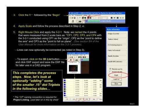
3. Click the R ++ followed by the “Begin”<br />
4. Apply Scale and follow the process described in Step 2, vi.<br />
5. Right Mouse Click and apply the 3-2-1. Note: we named the 4 points<br />
that were measured from 2 scale bars as: *CP1, CP2, CP3, and CP4 with<br />
the 3-2-1 conducted using CP1 as the “origin”, CP2 as the “point to define<br />
the axis” and CP3 as the “point to fall on plane”. (See section B4 <strong>of</strong> the<br />
User Manual for more information on the 3-2-1 process).<br />
- Lines can now optionally be connected (as noted in Step 3).<br />
- To export, click on the 3D List button<br />
and click DXF export and save the DXF file<br />
for later use in a CAD program.<br />
This completes the process<br />
steps. Now, let’s look at<br />
optionally “adding” some<br />
<strong>of</strong> the smaller .15” dot <strong>Triplet</strong>s<br />
in the following slides…<br />
* The “CP” naming convention is required for<br />
Project Linking, used later on in this tip sheet<br />
Slide 6