

TIP SHEET: Automatic Measurement of Triplet Offset Targets - iWitness
TIP SHEET: Automatic Measurement of Triplet Offset Targets - iWitness
TIP SHEET: Automatic Measurement of Triplet Offset Targets - iWitness

You also want an ePaper? Increase the reach of your titles
YUMPU automatically turns print PDFs into web optimized ePapers that Google loves.
<strong>TIP</strong> <strong>SHEET</strong>: <strong>Automatic</strong> <strong>Measurement</strong> <strong>of</strong> <strong>Triplet</strong> <strong>Offset</strong> <strong>Targets</strong><br />
for <strong>iWitness</strong>PRO TM V2<br />
Background:<br />
Background:<br />
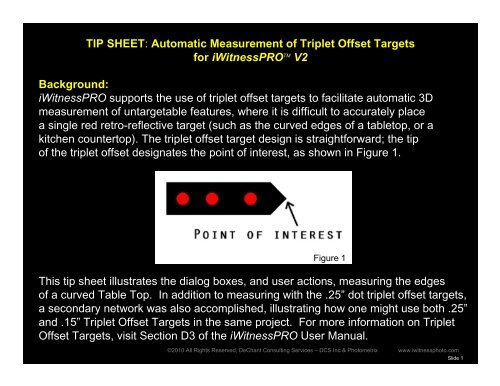
<strong>iWitness</strong>PRO supports the use <strong>of</strong> triplet <strong>of</strong>fset targets to facilitate automatic 3D<br />
measurement <strong>of</strong> untargetable features, where it is difficult to accurately place<br />
a single red retro-reflective target (such as the curved edges <strong>of</strong> a tabletop, or a<br />
kitchen countertop). The triplet <strong>of</strong>fset target design is straightforward; the tip<br />
<strong>of</strong> the triplet <strong>of</strong>fset designates the point <strong>of</strong> interest, as shown in Figure 1.<br />
Figure 1<br />
This tip sheet illustrates the dialog boxes, and user actions, measuring the edges<br />
<strong>of</strong> a curved Table Top. In addition to measuring with the .25” dot triplet <strong>of</strong>fset targets,<br />
a secondary network was also accomplished, illustrating how Figure one might 1 use both .25”<br />
and .15” <strong>Triplet</strong> <strong>Offset</strong> <strong>Targets</strong> in the same project. For more information on <strong>Triplet</strong><br />
<strong>Offset</strong> <strong>Targets</strong>, visit Section D3 <strong>of</strong> the <strong>iWitness</strong>PRO User Manual.<br />
©2010 All Rights Reserved, DeChant Consulting Services – DCS Inc & Photometrix www.iwitnessphoto.com<br />
Slide 1
Working with <strong>Triplet</strong> <strong>Offset</strong> <strong>Targets</strong> - (<strong>of</strong>ten referred to as “<strong>Triplet</strong>s”)<br />
STEP 1. Camera Settings<br />
We recommend using a DSLR Camera, with settings as follows:<br />
1. “Manual” set on the dial and also using Manual Focus<br />
2. Shutter Speed 1/125 th <strong>of</strong> a second<br />
3. *Aperture: about F13 (the goal is to UNDEREXPOSE the images a couple F-stops)<br />
4. ISO 400<br />
5. Always use the camera flash – the <strong>Triplet</strong> <strong>Targets</strong> and codes must be illuminated by the flash<br />
6. If your camera to target distance is only a few meters away, then we recommend the following:<br />
6a. Temporarily put the camera in “aut<strong>of</strong>ocus”.<br />
6b. Depress the shutter button half-way down (this will focus the lens making the triplets sharply focused)<br />
6c. With the camera still on, use the camera as described in step 1 through 5<br />
Alternatively, if the <strong>Triplet</strong> targets are in a camera-to-target range <strong>of</strong> 2m to say 6m, simply set the focus<br />
to “infinity”<br />
7. ALWAYS shoot the images in a mix <strong>of</strong> Landscape and Portrait shots – this is required for the camera’s<br />
Scale distance A | B<br />
self calibration - (see Part C, Section C2 <strong>of</strong> the User Manual for more information)<br />
STEP 2. <strong>iWitness</strong>PRO Settings<br />
In the Project Settings dialog (Edit + Project Settings) the Tick Mark for “<strong>Triplet</strong> <strong>Offset</strong> <strong>Targets</strong>” must be<br />
selected to ensure <strong>iWitness</strong>PRO automatically measures triplet <strong>of</strong>fset targets. Refer to Figure 2, for the<br />
proper settings. Note: the tick mark for the .25” Target configuration.<br />
•You can optionally ‘open up’ the shutter (to about F8) to allow more light, to manually measure Natural Features as well. This tip sheet was designed for<br />
the optimum exposure <strong>of</strong> <strong>Triplet</strong> <strong>Offset</strong> <strong>Targets</strong>, thus the reason the imagery appears “dark” or underexposed.<br />
Slide 2
i) ‘Red <strong>Targets</strong>’ must be selected;<br />
ii) ‘Find triplet <strong>of</strong>fset targets’ must be selected;<br />
iii) The physical size <strong>of</strong> the targets on the triplet <strong>of</strong>fset targets<br />
must be selected (either 0.15” or 0.25”);<br />
iv) NOTE: Scale MUST be set for an <strong>iWitness</strong>PRO network<br />
before the triplet <strong>of</strong>fset feature will function correctly. Optionally,<br />
scale via retro-reflective codes can be selected in the Project<br />
Settings dialog. For more accurate results, a scale bar (or scale<br />
bars) can be measured within the project.<br />
We recommend scaling using scale bars after running the “R ++ ”.<br />
Once the scale is applied, (Right Click “Set Scale…”) proceed to<br />
the 3D Points List and click the “Process” button. The <strong>Triplet</strong><br />
<strong>Offset</strong> Points are now presented in the 3D Points List and 3D<br />
View.<br />
STEP 3. Field Work<br />
Setting up the <strong>Triplet</strong> <strong>Targets</strong><br />
Figure 2<br />
To use triplet <strong>of</strong>fset targets, simply place any number <strong>of</strong> them within the scene <strong>of</strong> interest at the time<br />
<strong>of</strong> photography and <strong>iWitness</strong>PRO will automatically measure them during the R ++ process. <strong>Triplet</strong> <strong>of</strong>fset<br />
points are shown in dark blue in the images and the 3D List, and in red in the 3D View. Each time a<br />
photogrammetric bundle adjustment is run, the triplet <strong>of</strong>fset points are recalculated in 3D, and<br />
thus they are only temporary and not saved in the project file. They can, however, be exported via the 3D<br />
points dialog for example in .DXF format for consideration within third-party CAD s<strong>of</strong>tware.<br />
i)<br />
ii)<br />
iii)<br />
Slide 3
1. Photograph the project with the camera settings described in Step 1. Figure 3 used a quantity <strong>of</strong> 12<br />
coded targets, and two scale bars along with 100 <strong>Triplet</strong> <strong>Offset</strong> <strong>Targets</strong> defining the curved geometry<br />
(edges) <strong>of</strong> the Table Top. Note how the images are taken in a “ring pattern” around<br />
the table top. The camera was approximately 1.5 to 2.5 meters from the triplet targets. 10 images were<br />
used, but 20 were originally imaged. It is always better to take more photos than less.<br />
Table Top<br />
Figure 3<br />
Slide 4
STEP 4. <strong>iWitness</strong>PRO s<strong>of</strong>tware (computer) work<br />
2. Import the images into <strong>iWitness</strong>PRO<br />
2a. Follow the Step 2 settings.<br />
2b. Open one <strong>of</strong> the images and place the cursor within the image and click the keyboard “Q” key<br />
(see Figure 4) and click the Optimize! button. Click OK when complete, to close-out <strong>of</strong> the dialog box.<br />
Then, it is finished… ;-)<br />
Image Scanning & Auto<br />
<strong>Measurement</strong> settings<br />
(Q-key)<br />
Figure 4<br />
Slide 5
3. Click the R ++ followed by the “Begin”<br />
4. Apply Scale and follow the process described in Step 2, vi.<br />
5. Right Mouse Click and apply the 3-2-1. Note: we named the 4 points<br />
that were measured from 2 scale bars as: *CP1, CP2, CP3, and CP4 with<br />
the 3-2-1 conducted using CP1 as the “origin”, CP2 as the “point to define<br />
the axis” and CP3 as the “point to fall on plane”. (See section B4 <strong>of</strong> the<br />
User Manual for more information on the 3-2-1 process).<br />
- Lines can now optionally be connected (as noted in Step 3).<br />
- To export, click on the 3D List button<br />
and click DXF export and save the DXF file<br />
for later use in a CAD program.<br />
This completes the process<br />
steps. Now, let’s look at<br />
optionally “adding” some<br />
<strong>of</strong> the smaller .15” dot <strong>Triplet</strong>s<br />
in the following slides…<br />
* The “CP” naming convention is required for<br />
Project Linking, used later on in this tip sheet<br />
Slide 6
Overview <strong>of</strong> <strong>Triplet</strong> <strong>Offset</strong> Target Configurations:<br />
There are currently two different sizes <strong>of</strong> triplet <strong>of</strong>fset targets available; small and medium. Small triplet<br />
<strong>of</strong>fset targets have 0.15”/3.8mm targets (overall length 1.425”/36.2mm); and medium triplet <strong>of</strong>fset<br />
targets have 0.25"/6.35mm targets (overall length 2.875”/73.0mm). A larger <strong>Triplet</strong> will be available in<br />
a future release. <strong>Triplet</strong>s are illustrated in Figure 5. Different sizes <strong>of</strong> triplet <strong>of</strong>fset targets cannot be<br />
mixed within the same bundle adjustment (i.e., project), but the size <strong>of</strong> the triplet <strong>of</strong>fset targets can be<br />
different to the size <strong>of</strong> the coded targets via the Project Settings dialog. The small-sized triplet <strong>of</strong>fset<br />
targets are useful when there is a lot <strong>of</strong> detail to be measured in a small area, and the medium-sized<br />
triplet <strong>of</strong>fset targets are useful for normal scenes.<br />
Figure 5<br />
Slide 7
“Secondary objective” <strong>of</strong> the Demo Project: including the .15” triplet <strong>of</strong>fset targets<br />
Background:<br />
The demo project incorporated curves on the 4 corners <strong>of</strong> the Table Top (Figure 6). In this initial project,<br />
the .25” dot <strong>Triplet</strong>s are physically too large to try and place enough <strong>of</strong> them to define the curves, as noted in<br />
the areas <strong>of</strong> the red arrows in Figure 6.<br />
To better define the curves, a quantity <strong>of</strong> 11, .15” <strong>Triplet</strong> <strong>Offset</strong> <strong>Targets</strong> were survey independently,<br />
subsequent to the initial survey, <strong>of</strong> which originally used the .25” <strong>Triplet</strong>s. Figure 7, illustrates where<br />
a quantity <strong>of</strong> 3 <strong>of</strong> the .25” <strong>Triplet</strong>s were removed after the original survey, with another quantity <strong>of</strong> 3 <strong>of</strong> the<br />
.15” <strong>Triplet</strong>s placed in a second survey to better define the curve with more points. NOTE: the 12 coded<br />
targets and scale bars were not moved from the original survey, and were also used in the second survey.<br />
.25” <strong>Triplet</strong>s<br />
Remove<br />
Remove<br />
Remove<br />
.15” <strong>Triplet</strong>s<br />
Initial Survey Figure 6 Second Survey<br />
Figure 7<br />
Slide 8
Steps for the “Second Survey”<br />
1. Remove enough <strong>of</strong> the .25” <strong>Triplet</strong>s in the curved areas, so the .15” <strong>Triplet</strong>s can be applied adjacent<br />
to where the .25” <strong>Triplet</strong>s were imaged – (noted in Figure 6 and 7).<br />
2. The camera settings are the same as Step 1.<br />
3. In Step 2, iii) the <strong>Triplet</strong> Target Size needs to be changed from .25” to .15”.<br />
4. Photograph the areas <strong>of</strong> the<br />
applied .15” triplets similar to<br />
Step 3 (one needs to acquire<br />
at least 5 good overlapping<br />
perspective camera angle shots).<br />
Figure 8 illustrates eight<br />
different camera observations<br />
on a randomly selected .15”<br />
<strong>Triplet</strong> <strong>Offset</strong> Target.<br />
5. Complete the Step 4<br />
work, however there is No<br />
Need to “Scale” or “3-2-1”.<br />
The only requirement is to<br />
name the CP points the<br />
same as Step 4, item 5.<br />
6. Save the project a different<br />
name (e.g. “Secondary<br />
.iwpro”)<br />
CP1<br />
CP3<br />
CP4<br />
CP2<br />
Figure 8<br />
Slide 9
7. Close out <strong>of</strong> the project (assure there aren’t any projects (i.e. iwpro’s)<br />
minimized in the Windows TM task bar)).<br />
8. Click on the <strong>iWitness</strong>PRO short-cut and start a new project and select<br />
File + Import Projects for Linking… - see Figure 9.<br />
The Project Linking dialog is now displayed - see Figure 10.<br />
9. Click the Import… button as indicated in Figure 10.<br />
NOTE: the project “Network one (1)” you import<br />
will be the initial project accomplished. For this tip<br />
sheet, we named the initial project “Table Top.iwpro”.<br />
10. Click the Import… button as indicated in Figure 10.<br />
NOTE: the project “Network two (2)” you import<br />
will be the second project accomplished. For<br />
this tip sheet, we named the second project<br />
“Secondary.iwpro”.<br />
Figure 11 illustrates the coordinate transformation result.<br />
The Table Top.iwpro and the Secondary.iwpro are now<br />
in the same coordinate system, ready to export as a DXF<br />
file to a third party CAD program.<br />
Click for the noted Step 9<br />
Click for the noted Step 10<br />
Figure 10<br />
Figure 9<br />
Slide 10
Note the “RMS .006” (fit) in the upper right.<br />
With precision scaling, a decent consumer<br />
grade DSLR camera and a good self<br />
calibration, this result is typical <strong>of</strong> a project<br />
the size <strong>of</strong> the demo example networks.<br />
11. Click the “STEP 2 – Perform Linking”<br />
button (lower middle <strong>of</strong> dialog box).<br />
Note: as soon as you accomplish this,<br />
the “Step 3 – Generate .DXF” button<br />
will become ‘active’.<br />
12. Click the “STEP 3 – Generate .DXF”<br />
button” and save the .DXF to your<br />
working folder. Click “Close”.<br />
The project is now complete. Figure 12 & 13<br />
illustrate the results <strong>of</strong> the work in a CAD<br />
program. A series <strong>of</strong> 3-Point ARCS<br />
were used to connect the .25” and the .15”<br />
<strong>Triplet</strong> <strong>Offset</strong> <strong>Targets</strong>.<br />
NOTE: one can also compress the Z-axis<br />
to zero (0) in the <strong>iWitness</strong>PRO .DXF export<br />
options dialog box if the <strong>Triplet</strong>s are being<br />
used on a planar surface (XY Plane).<br />
Figure 11<br />
Slide 11
Figure 12<br />
Slide 12
Figure 13<br />
Slide Slide 13 13
Final Notes -- Tips for use <strong>of</strong> <strong>Triplet</strong> <strong>Offset</strong> <strong>Targets</strong>:<br />
i) Do not place triplet <strong>of</strong>fset targets too close to coded targets or single feature points, as they will function more<br />
consistently if left with some space (approximately 1-diameter <strong>of</strong> the overall size) surrounding them.<br />
ii) <strong>Triplet</strong> <strong>of</strong>fset targets should be spaced at least 2.5cm/1” apart from each other.<br />
iii) If a triplet <strong>of</strong>fset target is missed by <strong>iWitness</strong>PRO, it is possible to manually measure (i.e. force) it in the 3D<br />
view. Select the three points that form the missed triplet and press the ‘O’ key (Letter ‘O’) on the keyboard. This<br />
will identify the triplet <strong>of</strong>fset target and generate the <strong>of</strong>fset point. The three points forming the triplet <strong>of</strong>fset target<br />
must have been calculated correctly for this to work.<br />
iv) If <strong>iWitness</strong>PRO seems to miss a large number <strong>of</strong> triplet <strong>of</strong>fset targets in a survey, it may be useful to select<br />
Maximum Pts in the Image-Scanning & Auto-<strong>Measurement</strong> settings dialog, before rerunning a bundle<br />
adjustment.<br />
It is also possible to connect lines between <strong>of</strong>fset points, though once again these are only temporary and it is<br />
important to note that running the bundle adjustment will remove lines between <strong>of</strong>fset points. Therefore, lines<br />
should only be connected between <strong>of</strong>fset points once all other processes have been completed, and just prior<br />
to exporting a .DXF file. <strong>iWitness</strong>PRO will give a warning message for the first line that is measured between<br />
<strong>of</strong>fset points, giving an option to force the bundle adjustment to be “turned <strong>of</strong>f” to avoid accidentally removing<br />
lines between <strong>of</strong>fset points (see Figure 14). Similarly, <strong>iWitness</strong>PRO will give a warning message before turning<br />
the bundle back on (see Figure 15).<br />
Figure 14 Figure 15<br />
Slide 14