

A Novel Analysis of Voltage Distribution in Zinc Oxide Arrester using ...
A Novel Analysis of Voltage Distribution in Zinc Oxide Arrester using ...
A Novel Analysis of Voltage Distribution in Zinc Oxide Arrester using ...

You also want an ePaper? Increase the reach of your titles
YUMPU automatically turns print PDFs into web optimized ePapers that Google loves.
POSTER PAPER<br />
International Journal <strong>of</strong> Recent Trends <strong>in</strong> Eng<strong>in</strong>eer<strong>in</strong>g, Vol. 1, No. 4, May 2009<br />
A <strong>Novel</strong> <strong>Analysis</strong> <strong>of</strong> <strong>Voltage</strong> <strong>Distribution</strong><br />
<strong>in</strong> Z<strong>in</strong>c <strong>Oxide</strong> <strong>Arrester</strong> us<strong>in</strong>g<br />
F<strong>in</strong>ite Element method<br />
R.Karthik<br />
Lecturer-EEE Dept, National Eng<strong>in</strong>eer<strong>in</strong>g College, Kovilpatti, Tamilnadu,India<br />
E-mail: hvekarthik@gmail.com<br />
Abstract<br />
Necessity to preserve the cont<strong>in</strong>uity <strong>of</strong> service and electric<br />
supply demands special attention towards protection <strong>of</strong><br />
transmission l<strong>in</strong>es and power apparatus from over voltages.<br />
Lightn<strong>in</strong>g arresters are devices used at sub-stations and at<br />
l<strong>in</strong>e term<strong>in</strong>ations to discharge these over voltages, more<br />
particularly lightn<strong>in</strong>g surges and switch<strong>in</strong>g surges. The<br />
arresters <strong>in</strong>stalled today are almost all metal- oxide (MO)<br />
arresters without gaps. The dist<strong>in</strong>ctive feature <strong>of</strong> MO resistors<br />
is its extremely non-l<strong>in</strong>ear voltage characteristics, render<strong>in</strong>g<br />
unnecessary the disconnection <strong>of</strong> the resistors from the l<strong>in</strong>e<br />
through serial spark–gaps earlier used with Sic resistors.<br />
“Ref. [1]”The voltage distribution <strong>in</strong> a z<strong>in</strong>c oxide arrester<br />
under normal operat<strong>in</strong>g conditions has been observed to be<br />
non-uniform. The disc at the top are subject to higher voltage<br />
and hence thermal stresses lead<strong>in</strong>g to faster thermal age<strong>in</strong>g <strong>of</strong><br />
these highly stressed disc’s, therefore efforts are made to make<br />
the voltage distribution as uniform as possible.<br />
Lightn<strong>in</strong>g arresters for 110 kV, 220 kV, 380 kV systems were<br />
considered on application <strong>of</strong> maximum cont<strong>in</strong>uous operat<strong>in</strong>g<br />
voltage. For 220 kV, 380 kV system arresters, observation <strong>of</strong><br />
voltage distribution showed that voltage level to be high at the<br />
top discs <strong>of</strong> the arrester, which will lead to damage <strong>of</strong><br />
arresters. For stress to be relieved and voltage to be distributed<br />
uniformly through out the discs <strong>of</strong> arrester ‘Grade R<strong>in</strong>gs’ are<br />
employed .These grade r<strong>in</strong>gs control the voltage distribution<br />
from top to bottom <strong>of</strong> the arrester and uniform voltage<br />
distribution is achieved. In this paper an analysis <strong>of</strong> voltage<br />
distribution <strong>in</strong> lightn<strong>in</strong>g <strong>Arrester</strong> is done with the help <strong>of</strong> state<br />
<strong>of</strong> art <strong>of</strong> technology ANSYS7.1 which analysis through<br />
analytical method with F<strong>in</strong>ite element as basics<br />
Index terms- <strong>Arrester</strong>,F<strong>in</strong>ite Element method,Grade r<strong>in</strong>gs.<br />
I.INTRODUCTION<br />
High voltage power systems <strong>in</strong> general,<br />
experience over voltages that orig<strong>in</strong>ate from the<br />
system <strong>in</strong>stability/fault conditions, switch<strong>in</strong>g<br />
operations and lightn<strong>in</strong>g surges. The duration <strong>of</strong> the<br />
over voltages vary from micro seconds to seconds,<br />
depend<strong>in</strong>g upon the type <strong>of</strong> surges. Similarly the<br />
magnitude <strong>of</strong> the over-voltages vary from 1.15 to 4<br />
times the normal operat<strong>in</strong>g system voltage. Under<br />
these over voltage conditions, the <strong>in</strong>sulation <strong>of</strong> the<br />
power system/equipments could undergo stresses that<br />
lead to catastrophic failure. Hence, it is essential that<br />
the power system equipments are protected from these<br />
over voltages at the time <strong>of</strong> occurrence .The protection<br />
<strong>of</strong> power system equipments from the over- voltages is<br />
possible by the use <strong>of</strong> protective devices that posses<br />
variable impedance as a function <strong>of</strong> voltage<br />
© 2009 ACADEMY PUBLISHER<br />
1<br />
magnitude. The over- voltage protective device is<br />
usually connected <strong>in</strong> parallel to the<br />
equipment/system to be protected.<br />
Under normal operat<strong>in</strong>g voltage, the<br />
impedance <strong>of</strong> the over- voltage protective device is<br />
high and, hence allows the power system<br />
/equipments to perform the respective function.<br />
Whenever the over-voltage appears <strong>in</strong> the system,<br />
the impedance <strong>of</strong> the protective device reduces<br />
drastically to such an extent that the equipments<br />
will not experience the over-voltages due to<br />
potential drop. As soon as the over-voltage<br />
disappears the protective equipment rega<strong>in</strong>s the<br />
impedance and allows the power system<br />
equipments to perform the respective functions.<br />
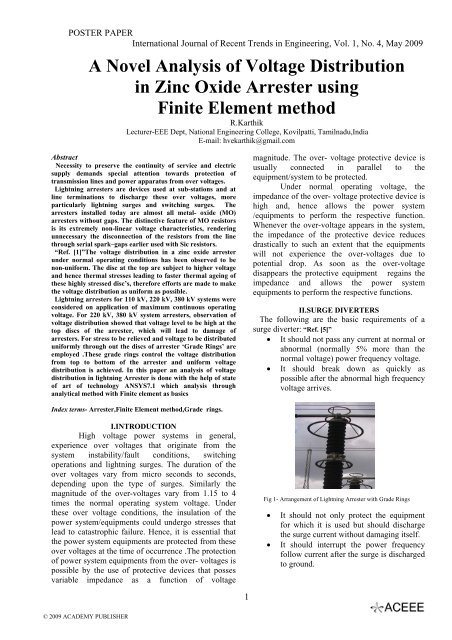
II.SURGE DIVERTERS<br />
The follow<strong>in</strong>g are the basic requirements <strong>of</strong> a<br />
surge diverter: “Ref. [5]”<br />
• It should not pass any current at normal or<br />
abnormal (normally 5% more than the<br />
normal voltage) power frequency voltage.<br />
• It should break down as quickly as<br />
possible after the abnormal high frequency<br />
voltage arrives.<br />
Fig 1- Arrangement <strong>of</strong> Lightn<strong>in</strong>g <strong>Arrester</strong> with Grade R<strong>in</strong>gs<br />
• It should not only protect the equipment<br />
for which it is used but should discharge<br />
the surge current without damag<strong>in</strong>g itself.<br />
• It should <strong>in</strong>terrupt the power frequency<br />
follow current after the surge is discharged<br />
to ground.
POSTER PAPER<br />
International Journal <strong>of</strong> Recent Trends <strong>in</strong> Eng<strong>in</strong>eer<strong>in</strong>g, Vol. 1, No. 4, May 2009<br />
A.BASIC FEATURES OF ZINC OXIDE<br />
ARRESTERS<br />
The basic constituent <strong>of</strong> ZnO gapless arresters is<br />
ZnO poly crystall<strong>in</strong>e element. The elements are<br />
housed <strong>in</strong> a hollow porcela<strong>in</strong> <strong>in</strong>sulator and<br />
hermetically sealed. The number and size <strong>of</strong> ZnO<br />
elements vary depend<strong>in</strong>g upon the system voltage and<br />
energy class requirements.<br />
“Ref. [2]”The resistivity <strong>of</strong> ZnO gra<strong>in</strong> is 1 to 10 ohm<br />
cm, whereas the gra<strong>in</strong> boundary resistivity is 10 10<br />
ohm cm.All the voltage applied to the element is<br />
concentrated across the high resistivity <strong>in</strong>ter granular<br />
layer. The resistance <strong>of</strong> the <strong>in</strong>ter granular layer<br />
decreases suddenly at a certa<strong>in</strong> threshold voltage as the<br />
applied voltage rises and so acts as a voltage<br />
dependent switch<strong>in</strong>g device.<br />
B.PROTECTIVE LEVELS<br />
Light<strong>in</strong>g impulse protective level <strong>of</strong> an<br />
arrester is the maximum residual voltage at the<br />
nom<strong>in</strong>al lightn<strong>in</strong>g discharge current.<br />
“Ref. [3]”Switch<strong>in</strong>g impulse protective level is<br />
the maximum residual voltage at the specified<br />
switch<strong>in</strong>g impulse current.<br />
Steep current impulse protective level is the<br />
maximum residual voltage correspond<strong>in</strong>g to a current<br />
impulse possess<strong>in</strong>g a virtual front time <strong>of</strong> one micro<br />
second with a peak value equal to the nom<strong>in</strong>al<br />
discharge current.<br />
C.APPLICATION OF GRADE RINGS:<br />
Grade r<strong>in</strong>gs are added to modify the voltage<br />
distribution across arresters at operat<strong>in</strong>g voltage to<br />
approach the ideal condition where voltage would be<br />
l<strong>in</strong>early distributed between arrester valve elements.<br />
“Ref. [1]” An arrester energized at operat<strong>in</strong>g<br />
voltage can be represented conceptually as a vertical<br />
column <strong>of</strong> a dielectric material <strong>in</strong>terspersed with<br />
metallic masses. when the through (from end-to-end)<br />
capacitance is not overwhelm<strong>in</strong>gly larger than the<br />
stray capacitance to ground <strong>of</strong> the metallic masses ,the<br />
voltage distribution along the vertical length <strong>of</strong> the<br />
column will be determ<strong>in</strong>ed by the <strong>in</strong>teraction <strong>of</strong> the<br />
through capacitance and the capacitance <strong>of</strong> the<br />
metallic masses. conceptually, the metallic masses will<br />
be capacitively coupled (through stray capacitance)to<br />
ground .Thus any metallic mass will tend to be at a<br />
lower voltage than would have been the case if<br />
there were there were no stray capacitance. The<br />
effect is to <strong>in</strong>crease the voltage gradient at the l<strong>in</strong>e<br />
end to reduce it at the ground end. In severe cases,<br />
(tall arresters with low through capacitance) the<br />
arrester elements near the l<strong>in</strong>e end <strong>of</strong> the arresters<br />
can be energized at such high voltage that the<br />
elements risk deterioration by thermal <strong>in</strong>stability.<br />
The solution is to modify the voltage<br />
distribution by external means so that the risk <strong>of</strong><br />
2<br />
© 2009 ACADEMY PUBLISHER<br />
thermal <strong>in</strong>stability <strong>of</strong> these elements is reduced to<br />
an acceptable level .Add<strong>in</strong>g stray capacitance to<br />
the l<strong>in</strong>e potential can tend to nullify the effect <strong>of</strong><br />
stray capacitance to ground, therefore tend to<br />
redistribute the voltage to approach the ideal<br />
uniform distribution. The grade r<strong>in</strong>g configuration<br />
is empirically determ<strong>in</strong>ed by select<strong>in</strong>g various<br />
grad<strong>in</strong>g r<strong>in</strong>g configurations and observ<strong>in</strong>g the<br />
voltage across strategically located arrester<br />
elements.<br />
III.ANALYSIS OF LIGHTNING ARRESTER<br />
WITH AND WITH OUT GRADE RINGS<br />
“Ref. [4]”<strong>Analysis</strong> <strong>of</strong> <strong>Voltage</strong> <strong>Distribution</strong> <strong>in</strong> Z<strong>in</strong>c<br />
<strong>Oxide</strong> <strong>Arrester</strong> is done with the help <strong>of</strong> state <strong>of</strong> art<br />
technology, (i.e.) ANSYS 7.1 s<strong>of</strong>tware package,<br />
which analyses through analytical method, with<br />
F<strong>in</strong>ite Element Method as basics.<br />
A.SOLIDLY EARTHED NEUTRAL 220 Kv<br />
SYSTEM.<br />
1. With Out Grade R<strong>in</strong>g<br />
<strong>Voltage</strong> <strong>in</strong> kV<br />
160<br />
140<br />
120<br />
100<br />
r<strong>in</strong>g<br />
2. With Grade R<strong>in</strong>g<br />
<strong>Voltage</strong> <strong>in</strong> kV<br />
80<br />
60<br />
40<br />
20<br />
<strong>Voltage</strong> <strong>Distribution</strong> <strong>in</strong> 220kV System<br />
(without Grade R<strong>in</strong>g)<br />
0<br />
0 2 4 6 8 10 12 14 16 18 20 22 24 26 28 30 32 34 36 38 40<br />
Disc Number from Top <strong>of</strong> <strong>Arrester</strong><br />
<strong>Voltage</strong> <strong>Distribution</strong> <strong>in</strong> 220kV System<br />
(with Grade R<strong>in</strong>g)<br />
160<br />
140<br />
120<br />
100<br />
80<br />
60<br />
40<br />
20<br />
0<br />
0 2 4 6 8 10 12 14 16 18 20 22 24 26 28 30 32 34 36 38 40<br />
Disc Number from Top <strong>of</strong> <strong>Arrester</strong><br />
Fig 3- 220 kV with Grade r<strong>in</strong>g<br />
Fig 2- 220 kV<br />
with out Grade
POSTER PAPER<br />
B.SOLIDLY EARTHED NEUTRAL 380 Kv<br />
SYSTEM<br />
1. With Out Grade R<strong>in</strong>g<br />
300<br />
250<br />
200<br />
150<br />
100<br />
50<br />
0<br />
Voltag e <strong>in</strong> kV<br />
Fig 4- 380 kV with out Grade r<strong>in</strong>g<br />
2. With Grade R<strong>in</strong>g<br />
© 2009 ACADEMY PUBLISHER<br />
International Journal <strong>of</strong> Recent Trends <strong>in</strong> Eng<strong>in</strong>eer<strong>in</strong>g, Vol. 1, No. 4, May 2009<br />
<strong>Voltage</strong> <strong>Distribution</strong> <strong>in</strong> 380kV System<br />
(without Grade R<strong>in</strong>g)<br />
0 3 6 9 12 15 18 21 24 27 30 33 36 39 42 45 48 51 54 57 60 63<br />
Disc Number from Top <strong>of</strong> <strong>Arrester</strong><br />
Fig 5- 380 kV with Grade r<strong>in</strong>g<br />
3<br />
From the above analysis it is observed that the<br />
disc at the top <strong>of</strong> the arrester are subject to<br />
higher voltage and hence thermal stresses lead<strong>in</strong>g<br />
to faster thermal age<strong>in</strong>g <strong>of</strong> these highly stressed<br />
discs, therefore after implement<strong>in</strong>g<br />
grade r<strong>in</strong>gs the voltage stresses at the top <strong>of</strong> the<br />
arrester disc are relieved and uniform voltage<br />
distribution is achieved.<br />
IV.CONCLUSION<br />
The F<strong>in</strong>ite Element analysis <strong>of</strong> the voltage<br />
distribution <strong>in</strong> ZnO arrester us<strong>in</strong>g ANSYS-7.1<br />
S<strong>of</strong>tware Package reveals the follow<strong>in</strong>g results,<br />
1. The voltage distribution is dependent on the<br />
geometry <strong>of</strong> the <strong>Arrester</strong>.<br />
2. Grade r<strong>in</strong>gs control the voltage distribution from<br />
top to bottom <strong>of</strong> the arrester and uniform voltage<br />
distribution is achieved and establishes that grade<br />
r<strong>in</strong>gs are required for system voltages greater than<br />
110 kV.<br />
Therefore by us<strong>in</strong>g the proper design <strong>of</strong> Light<strong>in</strong>g<br />
<strong>Arrester</strong>, us<strong>in</strong>g grade r<strong>in</strong>gs voltage distribution can<br />
be obta<strong>in</strong>ed <strong>in</strong> a uniform manner. Hence, the<br />
power l<strong>in</strong>es and sub-stations can be operated and<br />
protected aga<strong>in</strong>st over voltages such that the<br />
numbers <strong>of</strong> failures are as few as possible<br />
REFERENCE<br />
[1]. <strong>Voltage</strong> distribution <strong>in</strong> ZnO <strong>Arrester</strong>s- IEEE Proceed<strong>in</strong>gs<br />
Generation, Transmission and <strong>Distribution</strong>, Vol149, July2002<br />
[2]. Transient current distribution <strong>in</strong> ZnO arrester blocks.<br />
Cardiff University, Wales, UK<br />
[3]. Methods for analyz<strong>in</strong>g the performance <strong>of</strong> gapless metal<br />
oxide surge arresters, Ontario Hydro Research Div.Canada.<br />
[4].The Response <strong>of</strong> Metal <strong>Oxide</strong> Surge <strong>Arrester</strong>s to Steep<br />
Fronted Current Impulses, IEEE Transactions on Power<br />
Delivery, Vol.PWRD-1, NO-1, Jan-1986<br />
[5].High performance triggered lightn<strong>in</strong>g current arresters for<br />
<strong>in</strong>ternational power supply systems<br />
Wetter, M.; McCurdy, P.;<br />
Telecommunications Energy Conference, 2004. INTELEC<br />
2004. 26th Annual International<br />
19-23 Sept. 2004 Page(s):676 – 679<br />
[6]. Dielectric Stimulated Arcs <strong>in</strong> Lightn<strong>in</strong>g-Arrestor<br />
Connectors<br />
Bra<strong>in</strong>ard, J.; Andrews, L.;<br />
Components, Hybrids, and Manufactur<strong>in</strong>g Technology, IEEE<br />
Transactions on<br />
Volume 2, Issue 3, Sep 1979 Page(s):309 – 316


