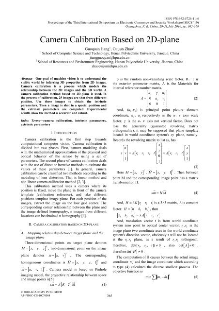
Camera Calibration Based on 2D-plane - Academy Publisher
Camera Calibration Based on 2D-plane - Academy Publisher
Camera Calibration Based on 2D-plane - Academy Publisher
Create successful ePaper yourself
Turn your PDF publications into a flip-book with our unique Google optimized e-Paper software.
ISBN 978-952-5726-11-4<br />
Proceedings of the Third Internati<strong>on</strong>al Symposium <strong>on</strong> Electr<strong>on</strong>ic Commerce and Security Workshops(ISECS ’10)<br />
Guangzhou, P. R. China, 29-31,July 2010, pp. 365-368<br />
<str<strong>on</strong>g>Camera</str<strong>on</strong>g> <str<strong>on</strong>g>Calibrati<strong>on</strong></str<strong>on</strong>g> <str<strong>on</strong>g>Based</str<strong>on</strong>g> <strong>on</strong> <strong>2D</strong>-<strong>plane</strong><br />
Guoquan Jiang 1 , Cuijun Zhao 2<br />
1<br />
School of Computer Science and Technology, Henan Polytechnic University, Jiaozuo, China<br />
jiangguoquan@hpu.edu.cn<br />
2<br />
School of Resources and Envir<strong>on</strong>ment Engineering, Henan Polytechnic University, Jiaozuo, China<br />
zhaocuijun@hpu.edu.cn<br />
Abstract—One goal of machine visi<strong>on</strong> is to understand the<br />
visible world by inferring 3D properties from <strong>2D</strong> images.<br />
<str<strong>on</strong>g>Camera</str<strong>on</strong>g> calibrati<strong>on</strong> is a process which models the<br />
relati<strong>on</strong>ship between the <strong>2D</strong> images and the 3D world. A<br />
camera calibrati<strong>on</strong> method based <strong>on</strong> <strong>2D</strong>-<strong>plane</strong> is used. In<br />
the process of calibrati<strong>on</strong>, 25 images are shot from different<br />
positi<strong>on</strong>. Use these images to obtain the intrinsic<br />
parameters. Then a image is shot in a special positi<strong>on</strong> and<br />
the extrinsic parameters are computed. Experimental<br />
results show the method is accurate and robust.<br />
Index Terms—camera calibrati<strong>on</strong>, intrinsic parameters,<br />
extrinsic parameters<br />
I. INTRODUCTION<br />
<str<strong>on</strong>g>Camera</str<strong>on</strong>g> calibrati<strong>on</strong> is the first step towards<br />
computati<strong>on</strong>al computer visi<strong>on</strong>. <str<strong>on</strong>g>Camera</str<strong>on</strong>g> calibrati<strong>on</strong> is<br />
divided into two phases. First, camera modeling deals<br />
with the mathematical approximati<strong>on</strong> of the physical and<br />
optical behavior of the sensor by using a set of<br />
parameters. The sec<strong>on</strong>d phase of camera calibrati<strong>on</strong> deals<br />
with the use of direct or iterative methods to estimate the<br />
values of these parameters [1]. In general, camera<br />
calibrati<strong>on</strong> can be classified two methods according to the<br />
modeling of lens distorti<strong>on</strong>. That is linear method and<br />
n<strong>on</strong>-linear camera calibrati<strong>on</strong> method [2, 3].<br />
This calibrati<strong>on</strong> method uses a camera where its<br />
positi<strong>on</strong> is fixed, move the <strong>plane</strong> in fr<strong>on</strong>t of the camera<br />
template (calibrati<strong>on</strong> reference), and take different<br />
positi<strong>on</strong>s template image <strong>plane</strong>. For each positi<strong>on</strong> of the<br />
images, extract the image <strong>on</strong> the four grid corner. The<br />
corresp<strong>on</strong>ding corner relati<strong>on</strong>ship between the <strong>plane</strong> and<br />
the image defined homography, n images from different<br />
locati<strong>on</strong>s can be obtained n homography [4].<br />
II. CAMERA CALIBRATION BASED ON <strong>2D</strong>-PLANE<br />
A. Mapping relati<strong>on</strong>ship between target <strong>plane</strong> and the<br />
image <strong>plane</strong><br />
Three-dimensi<strong>on</strong>al points <strong>on</strong> target <strong>plane</strong> denotes<br />
T<br />
M = x, y,<br />
z , two-dimensi<strong>on</strong>al point <strong>on</strong> the image<br />
[ ]<br />
<strong>plane</strong> denotes m<br />
T<br />
[ u,<br />
v]<br />
homogeneous coordinates is M [ x y z ]<br />
m [ u v ]<br />
= , The corresp<strong>on</strong>ding<br />
= , , , 1 T<br />
and<br />
= , , 1 T<br />
. <str<strong>on</strong>g>Camera</str<strong>on</strong>g> model is based <strong>on</strong> Pinhole<br />
imaging model, the projective relati<strong>on</strong>ship between space<br />
and image points is[5]<br />
sm = A[ R T] M <br />
(1)<br />
S is the random n<strong>on</strong>-vanishing scale factor, R、T is<br />
the exterior parameter matrix, A is the Materials for<br />
internal reference number matrix.<br />
⎡ax<br />
γ u0<br />
⎤<br />
A =<br />
⎢<br />
0 ay<br />
v<br />
⎥<br />
⎢ 0 ⎥<br />
(2)<br />
⎢⎣<br />
0 0 1 ⎥⎦<br />
And, ( u0, v0)<br />
is principal point picture element<br />
coordinate, ax、 ay<br />
respectively is the u、 v axis scale<br />
factor, γ is the u、 v axis not vertical factor. Does not<br />
lose the generality (guarantee revolving matrix<br />
orthog<strong>on</strong>ality), it may be supposed that <strong>plane</strong> template<br />
located in world coordinate system's xy <strong>plane</strong>, namely.<br />
Records the revolving matrix to list as, has<br />
⎡x⎤<br />
⎡u⎤<br />
⎢ x<br />
y<br />
⎥<br />
⎡ ⎤<br />
s<br />
⎢<br />
v<br />
⎥<br />
A[ r1 r2 r3 t] ⎢ ⎥ A[ r1 r2<br />
t<br />
⎢<br />
] y<br />
⎥<br />
⎢ ⎥<br />
= =<br />
⎢0⎥<br />
⎢ ⎥<br />
⎢⎣ 1⎥⎦<br />
⎢ ⎥<br />
⎢1⎥<br />
1<br />
⎣ ⎦<br />
⎣ ⎦<br />
(3)<br />
T<br />
Here M = [ x,<br />
y]<br />
, M = [ x, y, 1]<br />
T<br />
. Then between<br />
point M and the corresp<strong>on</strong>ding image point has a matrix<br />
transformati<strong>on</strong> H:<br />
And, H λK[ r1 r2<br />
t]<br />
factor. H = [ h1 h2 h3]<br />
, then<br />
[ h h h ] = λ A[ r r t]<br />
sm<br />
= HM<br />
(4)<br />
= is a 3×3 matrix, λ is c<strong>on</strong>stant<br />
1 2 3 1 2<br />
And, translati<strong>on</strong> vector t is from world coordinate<br />
system zero point to optical center vector; r 1<br />
, r 2<br />
is the<br />
image <strong>plane</strong> two coordinate axes in the world coordinate<br />
system's directi<strong>on</strong> vector, obviously t will not be located<br />
at the r 1<br />
, r 2<br />
<strong>plane</strong>, as a result of r 1<br />
, r 2<br />
orthog<strong>on</strong>al,<br />
therefore, det([ r1, r2, t]) ≠ 0 , also det[ A]<br />
≠ 0 ,<br />
therefore det[ H ] ≠ 0 .<br />
The computati<strong>on</strong> of H causes between the actual image<br />
coordinate m<br />
i<br />
and the image coordinate which according<br />
to type (4) calculates the diverse smallest process. The<br />
objective functi<strong>on</strong> is<br />
2<br />
min∑ m ˆ<br />
i<br />
− mi<br />
(5)<br />
i<br />
© 2010 ACADEMY PUBLISHER<br />
AP-PROC-CS-10CN008<br />
365
B. Solve camera parameter matrix<br />
The soluti<strong>on</strong> of the camera parameter matrix can be<br />
seen Literature[6].<br />
III. EXPERIMENT AND RESULTS<br />
A. Experiment materials<br />
KOKO camera; Image gathering card; Computer;<br />
Tripod; 7×9 the black and white interacti<strong>on</strong>'s chess<br />
discoid grid <strong>2D</strong> <strong>plane</strong> target (as shown in Figure 1), each<br />
grid size for 28×28 millimeter; Horiz<strong>on</strong>tal ir<strong>on</strong> sheet<br />
Figure 2. <str<strong>on</strong>g>Calibrati<strong>on</strong></str<strong>on</strong>g> with the 25 images<br />
Figure 1. <strong>2D</strong> <strong>plane</strong> for camera calibrati<strong>on</strong><br />
B. Experiment procedure<br />
1) Prints a calibrati<strong>on</strong> template to paste <strong>on</strong> the<br />
horiz<strong>on</strong>tal ir<strong>on</strong> sheet;<br />
2) moves <strong>plane</strong> or camera to shot some template<br />
images (more than or equal 20)from different angle;<br />
3) detects characteristic point of the image;<br />
4) obtains each image the unitary matrix H ;<br />
5) computes camera's internal parameter by using<br />
matrix H extracted in the premise of the distorti<strong>on</strong> factor<br />
being zero;<br />
6) obtains a group of precisi<strong>on</strong> higher camera's<br />
internal parameter by Further optimizing using the<br />
counter-projecti<strong>on</strong>, simultaneously calculating each<br />
distorti<strong>on</strong> factor.<br />
C. Experimental results<br />
1) Lens' internal parameter<br />
As shown in Figure 2, obtains internal parameter by<br />
Carrying <strong>on</strong> the demarcati<strong>on</strong> to the load 25 charts. Figure<br />
5-8 shows the spatial distributi<strong>on</strong> situati<strong>on</strong> for the 25<br />
images.<br />
The intrinsic parameters after camera calibrati<strong>on</strong> is<br />
Focal Length:<br />
f = c<br />
[3419.27498 3260.81444 ]<br />
±[88.56950 99.83080]<br />
Principle Point:<br />
cc = [383.50000 287.50000]<br />
± [0.00000 0.00000]<br />
Skew:<br />
alpha_c = [0.00000] ± [0.00000]<br />
Figure 3. The spatial distributi<strong>on</strong> for the 25 images<br />
Distortati<strong>on</strong>:<br />
kc = [-0.41925 -46.21000 -0.00466 -0.02250 0.00000]<br />
± [0.77140 78.34200 0.01162 0.00423 0.00000]<br />
Pixel error:<br />
err = [0.36731 0.79805]<br />
2) Computati<strong>on</strong> of the extrinsic parameters<br />
We put the <strong>plane</strong> pattern <strong>on</strong> the ground and shoot a<br />
image. Use this image to compute the extrinsic<br />
parameters.<br />
Extrinsic parameters:<br />
Translati<strong>on</strong> vector:<br />
⎡-77.629688<br />
⎤<br />
T =<br />
⎢<br />
-98.708815<br />
⎥<br />
⎢ ⎥<br />
⎢⎣<br />
1755.086388⎥⎦<br />
Rotati<strong>on</strong> vector:<br />
⎡ 0.019894 0.999776 -0.007244⎤<br />
R =<br />
⎢<br />
0.433706 -0.015158 -0.900927<br />
⎥<br />
⎢ ⎥<br />
⎢⎣<br />
-0.900835 0.014781 -0.433911⎥⎦<br />
Pixel error:<br />
err = [0.32229 0.69439]<br />
3) Experiment test<br />
366
TABLE I.<br />
THE COORDINATE OF MARKED POINTS AND THEIR CALIBRATION ERROR<br />
Marked points<br />
Image coordinate<br />
Real world coordinate<br />
Computati<strong>on</strong>al world<br />
coordinate<br />
u( pixels ) v( pixels ) x( cm ) ycm ( ) xˆ( cm ) ycm ˆ( )<br />
x directi<strong>on</strong>(<br />
cm<br />
)<br />
error<br />
y directi<strong>on</strong><br />
( cm )<br />
1 26 281 23.5 -9.5 21.74 -8.90 -1.76 0.60<br />
2 47 354 32 -7.5 29.39 -7.42 -2.61 0.08<br />
3 50 126 3 -10 3.00 -9.08 0.00 0.92<br />
4 60 195 13.5 -8.5 11.85 -8.00 -1.65 0.50<br />
5 81 496 46.5 -5 42.50 -5.17 -4.00 -0.17<br />
6 104 76 -4.5 -7.5 -3.86 -6.73 0.64 0.77<br />
7 183 258 20.5 -1.5 19.44 -1.85 -1.06 -0.35<br />
8 208 163 9 -1 8.12 -1.00 -0.88 0.00<br />
9 231 103 0 0 0.20 -0.03 0.20 -0.03<br />
10 235 402 37 1.5 34.32 0.82 -2.68 -0.68<br />
11 366 267 22 7.5 20.74 6.55 -1.26 -0.95<br />
12 367 435 40 7.5 37.55 6.34 -2.45 -1.16<br />
13 367 62 -6.5 7.5 -5.37 7.00 1.13 -0.50<br />
14 370 206 14.5 8 13.72 6.85 -0.78 -1.15<br />
15 373 122 3 8 3.06 7.18 0.06 -0.82<br />
16 375 559 52 7.5 48.02 6.48 -3.98 -1.02<br />
17 431 346 31 10.5 29.16 9.25 -1.84 -1.25<br />
18 535 238 18 16 17.74 14.46 -0.26 -1.54<br />
19 544 96 -1 17.5 -1.74 16.00 -0.74 -1.50<br />
20 552 395 36 16 34.11 14.21 -1.89 -1.79<br />
21 588 166 9.5 19.5 9.18 17.57 -0.32 -1.93<br />
22 689 82 -3 26 -1.86 23.61 1.14 -2.39<br />
23 721 430 40 23.5 37.58 20.98 -2.42 -2.52<br />
24 723 295 25 25 24.34 22.51 -0.66 -2.49<br />
25 725 515 48 23 44.92 20.34 -3.08 -2.66<br />
26 730 164 9 27 9.18 24.51 0.18 -2.49<br />
In order to verify the calibrati<strong>on</strong> algorithm’s accuracy,<br />
we keep the camera’s positi<strong>on</strong> and orientati<strong>on</strong> is<br />
unchangeable. The world coordinate system<br />
establishment is as the same as the Z. Zhang [6.]. 26<br />
marked points are pasted <strong>on</strong> the laboratory ground. Figure<br />
4 is the primary image shot by the camera. All the<br />
marking points’ world coordinate can be obtained by<br />
measuring, and the corresp<strong>on</strong>ding image coordinates can<br />
be got by image processing. Fig. 5 show the centroid<br />
coordinates of the marked point. We first use the image<br />
coordinate of the 26 points to rec<strong>on</strong>struct their world<br />
coordinate, and then compare them to the real world<br />
coordinate. Their corresp<strong>on</strong>ding error is the experimental<br />
error. The error can be evaluated by the following<br />
expressi<strong>on</strong>:<br />
m<br />
2 2<br />
( ∑ ( x ˆ ) ( ˆ<br />
i<br />
− xi + yi − yi)<br />
i=<br />
1<br />
Qk<br />
=<br />
(6)<br />
m<br />
where , ( xi, y<br />
i)<br />
, ( i = 1,2, , m)<br />
is the real world<br />
coordinate of the marked point, ( xˆ, y ˆ)<br />
, ( i = 1,2, , m)<br />
is<br />
the computed world coordinate by calibrati<strong>on</strong> method,<br />
m is the number of marked points.<br />
The experimental results can be seen from table 1.<br />
The overall error of world coordinates is:<br />
Figure 3. Marked points image<br />
Figure 4. Extracted centroid of marked points<br />
367
26<br />
∑<br />
( ( x − xˆ<br />
) + ( y − yˆ<br />
)<br />
i=<br />
1<br />
Qk<br />
=<br />
26<br />
= 2.0881( cm)<br />
2 2<br />
i i i i<br />
CONCLUSIONS:<br />
In this paper, a camera calibrati<strong>on</strong> method based <strong>on</strong><br />
<strong>2D</strong>-<strong>plane</strong> is adopted. It can obtain the intrinsic parameters<br />
by move the <strong>2D</strong>-<strong>plane</strong> orientati<strong>on</strong>s. The extrinsic<br />
parameters can be computed by the specific orientati<strong>on</strong>.<br />
Experimental result shows that this camera calibrati<strong>on</strong><br />
method can quickly and accurately solve the internal and<br />
external camera parameters.<br />
ACKNOWLEDGMENT<br />
This research is supported by the Doctoral Fund of<br />
Henan Polytechnic University (B2010-27).<br />
REFERENCES<br />
[1] Salvi,J,Armangue,X,Batlle,J A comparative review of<br />
camera calibrating methods with accuracy evaluati<strong>on</strong><br />
Pattern Recogniti<strong>on</strong> 35,(2002)1617-1635.<br />
[2] QIU Mao-lin,MA S<strong>on</strong>g-de,LI Yi.Overview of <str<strong>on</strong>g>Camera</str<strong>on</strong>g><br />
<str<strong>on</strong>g>Calibrati<strong>on</strong></str<strong>on</strong>g> for Computer Visi<strong>on</strong>[J].Acta Automatica<br />
Sinica,2000,26(1):43-55.<br />
[3] Chen Shuyuan, Tsai Wenhsiang. A systematic approach to<br />
analytic determinati<strong>on</strong> of camera parameters by line<br />
features [ J ]. Pattern Recogniti<strong>on</strong>, 1990, 23 (8), 859 - 877<br />
[4] Wei G, Ma S. Complete two - <strong>plane</strong> camera calibrati<strong>on</strong> and<br />
experimental comparis<strong>on</strong>s[D] . In Proc. ICCV’93. 1993<br />
:439 - 446<br />
[5] Ma s<strong>on</strong>g-de, Zhang zheng-you. Computer Visi<strong>on</strong>. Science<br />
Publishing company, 2003<br />
[6] Zhang Z. Aflexible new technique for camera calibrati<strong>on</strong>[J<br />
] . IEEE Transacti<strong>on</strong> <strong>on</strong> Pattern Analysis andMachine<br />
Intelligence , 2002 ,22 (11) : 1330 - 1334<br />
368


