PULSER HC-LON INSTRUKTION INSTRUKTION Triac ... - regin
PULSER HC-LON INSTRUKTION INSTRUKTION Triac ... - regin
PULSER HC-LON INSTRUKTION INSTRUKTION Triac ... - regin

Create successful ePaper yourself
Turn your PDF publications into a flip-book with our unique Google optimized e-Paper software.
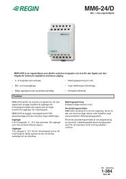
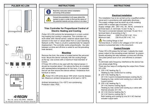
Fig 1<br />
Fig 2<br />
Fig 3<br />
<strong>PULSER</strong> <strong>HC</strong>-<strong>LON</strong><br />
94 43<br />
13 14 15 16<br />
a b c d<br />
J3<br />
CN1<br />
Box 116 428 22 KÅLLERED SWEDEN<br />
Tel +46 (0)31 720 02 00 Fax +46 (0)31 720 02 50<br />
J1<br />
150<br />
3137D APR 13<br />
i<br />
INSTRUCTIONS INSTRUCTIONS<br />
Read this instruction before installation<br />
and wiring of the product<br />
Consult documentation in all cases where this<br />
symbol is used, in order to find out the nature of<br />
the potential hazards and any actions to be taken<br />
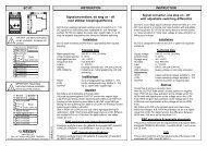
<strong>Triac</strong> Controller for Proportional Control of<br />
Electric Heating and Cooling<br />
Pulser <strong>HC</strong>-<strong>LON</strong> controls the temperature in a room controlling<br />
heating and cooling in sequence. The controller can<br />
work either with internal sensor, external values taken from<br />
sensors in the room or values taken from a Local Operating<br />
Network (<strong>LON</strong>). There is a built-in potentiometer for setpoint<br />
displacement. The controller works proportionally - the ratio<br />
between on-time and off-time is varied to suit the prevailing<br />
heat demand.<br />
Mounting<br />
Remove the front, the screw is located behind the set-point<br />
knob. Mount the device vertically with the cooling flange<br />
at the top. Use screws with a maximum head diameter of<br />
5.5mm.<br />
If Pulser <strong>HC</strong>-<strong>LON</strong> is to be used with the internal sensor, it<br />
should be mounted about 1.5m above the floor at a location<br />
with representative temperature for the room. It is essential<br />
that air can flow around the device without hinderance from<br />
furniture or doors.<br />
Pulser <strong>HC</strong>-<strong>LON</strong> emits about 10W which must be dissipated.<br />
Maximum ambient temperature at full load is +30°C.<br />
Ambient temperature: 0 to +30°C non-condensing.<br />
Protection class: IP20.<br />
Electrical Installation<br />
The installation has to be carried out by a qualified professional<br />
and in accordance with applicable directives.<br />
The supply voltage must be wired via a fully isolating<br />
switch with a contact gap of at least 3 mm,<br />
Supply voltage: 200...250 V AC, 50...60 Hz connects to<br />
terminal block J3, terminals 13 and 14 (fig 1).<br />
The load is connected between terminals 15 and 16 in<br />
terminal block J3 according to fig 1.<br />
Maximum load: 2300 W at 230 V AC, 10 A.<br />
Minimum load: 230 W at 230 V AC, 1 A.<br />
The cooling flange is live!<br />
Terminal block J1 which is for voltages of 24 V AC and<br />
sensors is presented later in this document.<br />
Control Principle<br />
Pulser <strong>HC</strong>-<strong>LON</strong> pulses the full load. It adjusts the mean<br />
power output to the prevailing power demand by proportionally<br />
adjusting the ratio between on-time and off-time.<br />
The pulse period (sum of on- and off-time) is constant<br />
60s.<br />
To eliminate radio frequency interference the device has<br />
zero phase-angle firing.<br />
There are four ways of configuring the output from Pulser<br />
<strong>HC</strong>-<strong>LON</strong>.<br />
1: 230 V AC heating (fig 1).<br />
Heating by triac control but no cooling<br />
2: 230 V AC heating (fig 1).<br />
24 V AC 3-point (increase/decrease) cooling (fig 5).<br />
Heating by triac control and cooling by a valve with<br />
3-point control.<br />
3: 230 V AC heating (fig 1).<br />
24 V AC thermo cooling (fig 6).<br />
Heating by triac control and cooling by a valve with<br />
thermal actuator 24 V AC.<br />
4: 24 V AC thermo heating (fig 7).<br />
24 V AC thermo cooling (fig 7).<br />
Both heating and cooling by one 24 V AC thermal<br />
actuator output each.