PULSER HC-LON INSTRUKTION INSTRUKTION Triac ... - regin
PULSER HC-LON INSTRUKTION INSTRUKTION Triac ... - regin
PULSER HC-LON INSTRUKTION INSTRUKTION Triac ... - regin

Create successful ePaper yourself
Turn your PDF publications into a flip-book with our unique Google optimized e-Paper software.
Fig 4<br />
Fig 5<br />
Fig 6<br />
Fig 7<br />
<strong>PULSER</strong> <strong>HC</strong>-<strong>LON</strong><br />
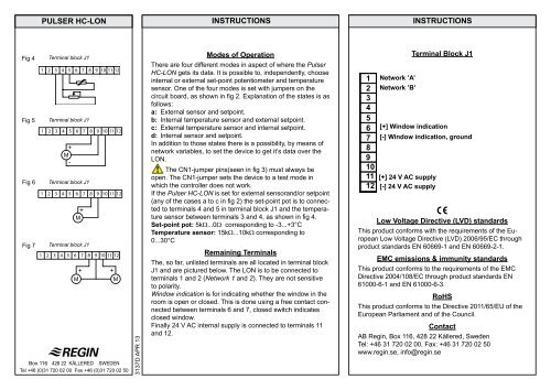
Terminal block J1<br />
1 2 3 4 5 6 7 8 9 10 11 12<br />
Terminal block J1<br />
1 2 3 4 5 6 7 8 9 10 11 12<br />
Terminal block J1<br />
1 2 3 4 5 6 7 8 9 10 11 12<br />
Terminal block J1<br />
1 2 3 4 5 6 7 8 9 10 11 12<br />
Box 116 428 22 KÅLLERED SWEDEN<br />
Tel +46 (0)31 720 02 00 Fax +46 (0)31 720 02 50<br />
3137D APR 13<br />
INSTRUCTIONS INSTRUCTIONS<br />
Modes of Operation<br />
There are four different modes in aspect of where the Pulser<br />
<strong>HC</strong>-<strong>LON</strong> gets its data. It is possible to, independently, choose<br />
internal or external set-point potentiometer and temperature<br />
sensor. One of the four modes is set with jumpers on the<br />
circuit board, as shown in fig 2. Explanation of the states is as<br />
follows:<br />
a: External sensor and setpoint.<br />
b: Internal temperature sensor and external setpoint.<br />
c: External temperature sensor and internal setpoint.<br />
d: Internal sensor and setpoint.<br />
In addition to those states there is a possibility, by means of<br />
network variables, to set the device to get it’s data over the<br />
<strong>LON</strong>.<br />
The CN1-jumper pins(seen in fig 3) must always be<br />
open. The CN1-jumper sets the device to a test mode in<br />
which the controller does not work.<br />
If the Pulser <strong>HC</strong>-<strong>LON</strong> is set for external sensorand/or setpoint<br />
(any of the cases a to c in fig 2) the set-point pot is to connected<br />
to terminals 4 and 5 in terminal block J1 and the temperature<br />
sensor between terminals 3 and 4, as shown in fig 4.<br />
Set-point pot: 5kΩ...0Ω corresponding to -3...+3°C<br />
Temperature sensor: 15kΩ...10kΩ corresponding to<br />
0...30°C<br />
Remaining Terminals<br />
The, so far, unlisted terminals are all located in terminal block<br />
J1 and are pictured below. The <strong>LON</strong> is to be connected to<br />
terminals 1 and 2 (Network 1 and 2). They are not sensitive<br />
to polarity.<br />
Window indication is for indicating whether the window in the<br />
room is open or closed. This is done using a free contact connected<br />
between terminals 6 and 7, closed switch indicates<br />
closed window.<br />
Finally 24 V AC internal supply is connected to terminals 11<br />
and 12.<br />
Terminal Block J1<br />
1 Network ’A’<br />
2 Network ’B’<br />
3<br />
4<br />
5<br />
6 [+] Window indication<br />
7 [-] Window indication, ground<br />
8<br />
9<br />
10<br />
11 [+] 24 V AC supply<br />
12 [-] 24 V AC supply<br />
Low Voltage Directive (LVD) standards<br />
This product conforms with the requirements of the European<br />
Low Voltage Directive (LVD) 2006/95/EC through<br />
product standards EN 60669-1 and EN 60669-2-1.<br />
EMC emissions & immunity standards<br />
This product conforms to the requirements of the EMC<br />
Directive 2004/108/EC through product standards EN<br />
61000-6-1 and EN 61000-6-3.<br />
RoHS<br />
This product conforms to the Directive 2011/65/EU of the<br />
European Parliament and of the Council.<br />
Contact<br />
AB Regin, Box 116, 428 22 Kållered, Sweden<br />
Tel: +46 31 720 02 00, Fax: +46 31 720 02 50<br />
www.<strong>regin</strong>.se, info@<strong>regin</strong>.se