Revolution V1 Generation 1 Quick Start Guide - Arrow Architectural ...
Revolution V1 Generation 1 Quick Start Guide - Arrow Architectural ...
Revolution V1 Generation 1 Quick Start Guide - Arrow Architectural ...
Create successful ePaper yourself
Turn your PDF publications into a flip-book with our unique Google optimized e-Paper software.
2<br />
1<br />
(2) 8-32 x 3/4"<br />
Flat Head<br />
Combination Screws<br />
(2) 8-32 x 3/4"<br />
Flat Head<br />
Combination Screws<br />
Components<br />
<strong>Quick</strong> <strong>Start</strong> Instructions<br />
Installation Instructions<br />
Door Marker<br />
Outside Touchscreen Assembly<br />
Inside Support Assembly<br />
Inside Escutcheon Assembly:<br />
• Inside Support Assembly<br />
• Inside Escutcheon<br />
• Inside Lever Handle<br />
• Battery Cover<br />
4 AA Alkaline Batteries<br />
Latchbolt<br />
Strike<br />
Allen Wrench 3/32” (2.5 mm)<br />
Screw Pack (7 screws)<br />
2 Keys (If Cylinder Included)<br />
For Technical Assistance call <strong>Arrow</strong>:<br />
1-800-221-6529.<br />
3<br />
Outside Assembly<br />
Directions<br />
1<br />
3a<br />
3b<br />
Motor Cable<br />
4<br />
<strong>Quick</strong>start <strong>Guide</strong><br />
Touchscreen<br />
Cable<br />
5<br />
Inside Assembly<br />
9<br />
Support Assembly Screws<br />
(2) 10-32 x 2-1/2" Flat<br />
Head Machine Screws<br />
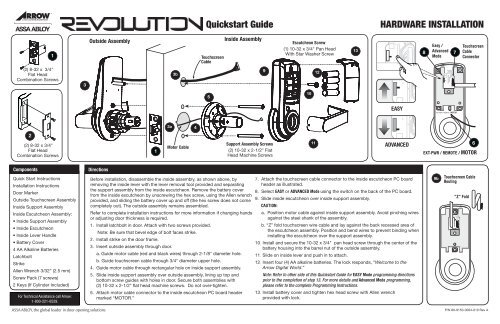
Before installation, disassemble the inside assembly, as shown above, by<br />
removing the inside lever with the lever removal tool provided and separating<br />
the support assembly from the inside escutcheon. Remove the battery cover<br />
from the inside escutcheon by unscrewing the hex screw, using the Allen wrench<br />
provided, and sliding the battery cover up and off (the hex screw does not come<br />
completely out). The outside assembly remains assembled.<br />
Refer to complete installation instructions for more information if changing hands<br />
or adjusting door thickness is required.<br />
1. Install latchbolt in door. Attach with two screws provided.<br />
Note: Be sure that bevel edge of bolt faces strike.<br />
2. Install strike on the door frame.<br />
3. Insert outside assembly through door.<br />
a. <strong>Guide</strong> motor cable (red and black wires) through 2-1/8" diameter hole.<br />
b. <strong>Guide</strong> touchscreen cable through 3/4" diameter upper hole.<br />
4. <strong>Guide</strong> motor cable through rectangular hole on inside support assembly.<br />
5. Slide inside support assembly over outside assembly, lining up top and<br />
bottom screw guides with holes in door. Secure both assemblies with<br />
(2) 10-32 x 2-1/2" flat head machine screws. Do not over-tighten.<br />
6. Attach motor cable connector to the inside escutcheon PC board header<br />
marked “MOTOR.”<br />
Escutcheon Screw<br />
(1) 10-32 x 3/4" Pan Head<br />
With Star Washer Screw<br />
10<br />
11<br />
12<br />
13<br />
EASY<br />
ADVANCED<br />
7. Attach the touchscreen cable connector to the inside escutcheon PC board<br />
header as illustrated.<br />
8. Select EASY or ADVANCED Mode using the switch on the back of the PC board.<br />
9. Slide inside escutcheon over inside support assembly.<br />
CAUTION:<br />
a. Position motor cable against inside support assembly. Avoid pinching wires<br />
against the steel shank of the assembly.<br />
b. “Z” fold touchscreen wire cable and lay against the back recessed area of<br />
the escutcheon assembly. Position and bend wires to prevent binding when<br />
installing the escutcheon over the support assembly.<br />
10. Install and secure the 10-32 x 3/4" pan head screw through the center of the<br />
battery housing into the barrel nut of the outside assembly.<br />
11. Slide on inside lever and push in to attach.<br />
12. Insert four (4) AA alkaline batteries. The lock responds, “Welcome to the<br />
<strong>Arrow</strong> Digital World.”<br />
Note: Refer to other side of this <strong>Quick</strong>start <strong>Guide</strong> for EASY Mode programming directions<br />
prior to the completion of step 13. For more details and Advanced Mode programming,<br />
please refer to the complete Programming Instructions.<br />
13. Install battery cover and tighten hex head screw with Allen wrench<br />
provided with lock.<br />
HARDWARE INSTALLATION<br />
8<br />
Easy /<br />
Advanced<br />
Mode<br />
7<br />
EXT-PWR / REMOTE / MOTOR<br />
Touchscreen<br />
Cable<br />
Connector<br />
6<br />
EXT-PWR / REMOTE / MOTOR<br />
9b Touchscreen Cable<br />
Routing<br />
"Z" Fold<br />
P/N 80-9150-0064-010 Rev A
Introduction Feature Programming Through Menu Mode Using the Supervisor Code<br />
Open Door With PIN Code<br />
This <strong>Quick</strong>start <strong>Guide</strong> is for programming in<br />
Easy Mode. For more details and Advanced Mode<br />
programming, please refer to the complete<br />
Programming Instructions.<br />
• For proper security, the Supervisor or Master<br />
PIN code should be changed as soon as<br />
the lock is installed.<br />
• The factory default setting is Easy Mode. In<br />
Easy Mode, one Supervisor and eight User<br />
PIN code locations are available.<br />
• In Easy Mode, when there are any additions<br />
or changes to codes, all existing PIN codes<br />
ARE DELETED and must be re-entered.<br />
PIN Code Programming Instructions (Easy Mode) Using the “ I ” Button<br />
S U<br />
• PIN codes can be 4 to 12 digits in length.<br />
• The button is located under the<br />
battery cover above the batteries.<br />
• The key is used to enter or accept an<br />
entry, and also to conclude a programming<br />
session.<br />
• The key is used either to enter or to<br />
continue additional steps in a programming<br />
sequence.<br />
• The factory default PIN code in Easy Mode:<br />
Supervisor: 1 2 3 4 5 6 7 8 9 0<br />
• The factory default PIN code in Advanced<br />
Mode: Master: 1 2 3 4 5 6<br />
Note: Be sure PIN codes are recorded. Entering any new code erases the existing codes.<br />
1. Unscrew battery cover hex screw using<br />
tool provided. Slide battery cover up<br />
and off to reveal the button located<br />
above the batteries.<br />
2. Press the button once.<br />
Lock response: “Register User code.<br />
Enter one Supervisor then up to 8 users.<br />
Enter a 4 to 12 digit PIN code, each<br />
followed by the key. Press the<br />
button to complete.”<br />
3. Enter the new Supervisor PIN code<br />
(4 to 12 digits) followed by the key.<br />
Lock Response: Sounds a tone for each<br />
PIN code digit with digits flashing in the<br />
sequence entered to confirm the entry.<br />
Chime signals when playback is complete.<br />
4. Enter the first User PIN code (4 to 12 digits)<br />
followed by the key.<br />
Lock Response: Sounds a tone for each<br />
PIN code digit with digits flashing in the<br />
sequence entered to confirm the entry.<br />
Chime signals when playback is complete.<br />
5. Continue to enter additional User PIN codes<br />
(4 to 12 digits each) followed by the key.<br />
Up to eight User PIN codes can be entered.<br />
6. Press the button to complete the<br />
process after the last playback sequence.<br />
Lock Response: “Registered.”<br />
1 2 3 4 5 6<br />
For Technical Assistance call <strong>Arrow</strong>:<br />
1-800-221-6529.<br />
1 - 8<br />
<strong>Quick</strong>start <strong>Guide</strong><br />
1. Touch the screen with the palm of your hand or fingers to acitivate .<br />
2. Enter the 4-12 digit Supervisor PIN code followed by the key.<br />
Lock Response: “Menu mode, enter number, press the key to continue.”<br />
3. Enter digit corresponding to the function to be performed.<br />
Follow the verbal commands.<br />
4. Press the key to complete the process and conclude the programming session.<br />
1 2<br />
I Button<br />
S<br />
Register User Code<br />
Passage Mode<br />
Silent Mode<br />
Language Mode<br />
EASY MODE PROGRAMMING INSTRUCTIONS<br />
3 4<br />
U<br />
Enable<br />
Disable<br />
Enable<br />
Disable<br />
English<br />
Spanish<br />
French<br />
1 - 8<br />
1. Touch the screen with<br />
the palm of your hand or<br />
fingers to activate.<br />
2. Enter PIN code.<br />
3. Palm or touch the<br />
key to confirm the<br />
selection.<br />
4. Turn lever to<br />
open door.<br />
P/N 80-9150-0064-010 Rev A


