Process Analytics in Gas-to-Liquid (GTL) Plants - Siemens Industry ...
Process Analytics in Gas-to-Liquid (GTL) Plants - Siemens Industry ...
Process Analytics in Gas-to-Liquid (GTL) Plants - Siemens Industry ...

Create successful ePaper yourself
Turn your PDF publications into a flip-book with our unique Google optimized e-Paper software.
Syngas generation (ctd.)<br />
Syngas conversion (FT Synthesis)<br />
FT Synthesis<br />
In the FT Synthesis, synthesis gas is converted<br />
<strong>in</strong><strong>to</strong> liquid hydrocarbon cha<strong>in</strong>s<br />
based on the famous „FT Chemistry“.<br />
In the cha<strong>in</strong> growth reaction a wide<br />
scope of products is formed rang<strong>in</strong>g<br />
from very light <strong>to</strong> heavy paraff<strong>in</strong>s.<br />
The most important element of this<br />
reaction is the type of catalyst used.<br />
Two predom<strong>in</strong>ant formulations are <strong>in</strong><br />
use, one based on iron and the other on<br />
cobalt. Both feature advantages and disadvantages<br />
and differ, amongst others,<br />
<strong>in</strong> their suitability with respect <strong>to</strong> feed<br />
composition and desired product scope.<br />
Besides the catalyst, the design and<br />
operation pr<strong>in</strong>ciple of the conversion<br />
reac<strong>to</strong>r is another key element. Various<br />
types of FT reac<strong>to</strong>r systems are <strong>in</strong> use,<br />
which have <strong>in</strong> common the need <strong>to</strong><br />
remove the exothermic heat of the<br />
reaction. But they show also fundamental<br />
differences.<br />
Fixed bed reac<strong>to</strong>r<br />
This is a reac<strong>to</strong>r that uses a catalyst<br />
packed <strong>in</strong> vertical tubes surrounded by<br />
a coolant medium and arranged <strong>in</strong> a<br />
vertical vessel. The syngas flows downwards<br />
through the tubes and heat<br />
is removed through the tube walls<br />
<strong>to</strong> produce steam.<br />
4<br />
© <strong>Siemens</strong> AG 2007<br />
Sampl<strong>in</strong>g po<strong>in</strong>t<br />
Measur<strong>in</strong>g<br />
Suitable Analyzer<br />
Sampl<strong>in</strong>g stream<br />
Components<br />
1.1 Satura<strong>to</strong>r<br />
Total S<br />
MAXUM<br />
Condensate stabilizer<br />
H2S MAXUM<br />
1.2 Hydrogenation/ Desulphurization Total S, H2S, CO2 Mercaptans<br />
MAXUM<br />
MAXUM<br />
Claus off gas<br />
O2, SO2 OXYMAT 6, TPA<br />
1.3 Dehydration/ Mercaptan removal RSH, Total S, COS, H2S MAXUM<br />
1.4 LPG RSH, Total S, COS, H2S, Mercaptans<br />
MAXUM<br />
1.5 Propane, Butane product C2-C4, C3-C5+ MAXUM / MicroSAM<br />
1.6 Treated NG Total S (ppm/ppb) MAXUM<br />
1.7/1.8 Various furnaces flue gases and<br />
process off gases<br />
O2, SO2, NOx, H2, ... OXYMAT 6, ULTRA-<br />
MAT 6, CALOMAT 6<br />
1.9 Raw Syngas CH4 , CO2 ULTRAMAT 6<br />
1.10 Syngas H2 , CO, CO2 , N2 , CH4 ,<br />
COS, H2S, TS<br />
MAXUM<br />
TPA: Third party analyzer<br />
Table 1: <strong>Process</strong> analyzer measurg<strong>in</strong>g tasks <strong>in</strong> syngas generation section (corresp. <strong>to</strong> Fig. 2)<br />
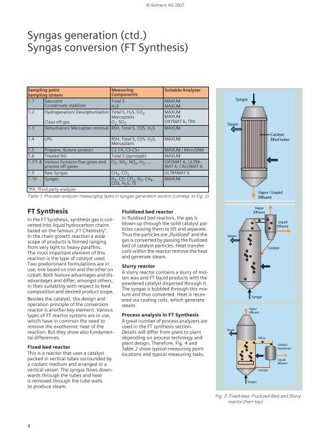
Fluidized bed reac<strong>to</strong>r<br />
In fluidized bed reac<strong>to</strong>rs, the gas is<br />
blown up through the solid catalyst particles<br />
caus<strong>in</strong>g them <strong>to</strong> lift and separate.<br />
Thus the particles are „fluidized“ and the<br />
gas is converted by pass<strong>in</strong>g the fluidized<br />
bed of catalyst particles. Heat transfer<br />
coils with<strong>in</strong> the reac<strong>to</strong>r remove the heat<br />
and generate steam.<br />
Slurry reac<strong>to</strong>r<br />
A slurry reac<strong>to</strong>r conta<strong>in</strong>s a slurry of molten<br />
wax and FT liquid products with the<br />
powdered catalyst dispersed through it.<br />
The syngas is bubbled through this mixture<br />
and thus converted. Heat is recovered<br />
via cool<strong>in</strong>g coils, which generate<br />
steam.<br />
<strong>Process</strong> analysis <strong>in</strong> FT Synthesis<br />
A great number of process analyzers are<br />
used <strong>in</strong> the FT synthesis section.<br />
Details will differ from plant <strong>to</strong> plant<br />
depend<strong>in</strong>g on process technlogy and<br />
plant design. Therefore, Fig. 4 and<br />
Table 2 show typical measur<strong>in</strong>g po<strong>in</strong>t<br />
locations and typical measur<strong>in</strong>g tasks.<br />
Steam<br />
Steam<br />
Steam<br />
Syngas<br />
Syngas<br />
Syngas<br />
Catalyst<br />
filled tubes<br />
Vapor / <strong>Liquid</strong><br />
Effluent<br />
Vapor<br />
Effluent<br />
Vapor<br />
Effluent<br />
Slurry<br />
Catalyst<br />
Catalyst<br />
<strong>Liquid</strong><br />
Effluent<br />
Catalyst<br />
Separation<br />
<strong>Liquid</strong><br />
Effluent<br />
Fig. 3: Fixed-bed, Fluidized-Bed and Slurry<br />
reac<strong>to</strong>r (from <strong>to</strong>p)