Process Analytics in Gas-to-Liquid (GTL) Plants - Siemens Industry ...
Process Analytics in Gas-to-Liquid (GTL) Plants - Siemens Industry ...
Process Analytics in Gas-to-Liquid (GTL) Plants - Siemens Industry ...

Create successful ePaper yourself
Turn your PDF publications into a flip-book with our unique Google optimized e-Paper software.
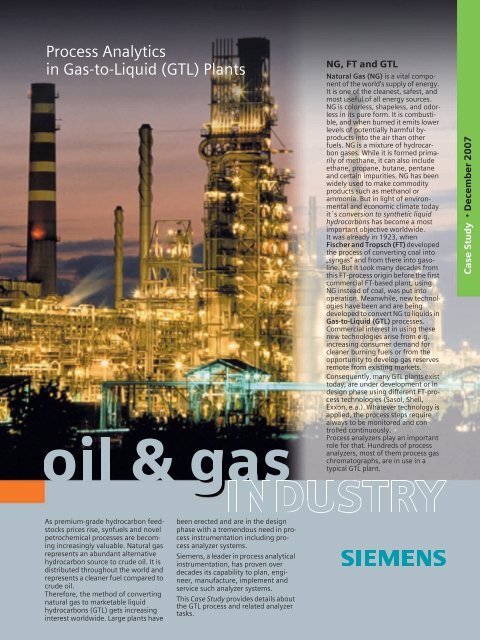
As premium-grade hydrocarbon feeds<strong>to</strong>cks<br />
prices rise, synfuels and novel<br />
petrochemical processes are becom<strong>in</strong>g<br />
<strong>in</strong>creas<strong>in</strong>gly valuable. Natural gas<br />
represents an abundant alternative<br />
hydrocarbon source <strong>to</strong> crude oil. It is<br />
distributed throughout the world and<br />
represents a cleaner fuel compared <strong>to</strong><br />
crude oil.<br />
Therefore, the method of convert<strong>in</strong>g<br />
natural gas <strong>to</strong> marketable liquid<br />
hydrocarbons (<strong>GTL</strong>) gets <strong>in</strong>creas<strong>in</strong>g<br />
<strong>in</strong>terest worldwide. Large plants have<br />
© <strong>Siemens</strong> AG 2007<br />
<strong>Process</strong> <strong>Analytics</strong><br />
<strong>in</strong> <strong>Gas</strong>-<strong>to</strong>-<strong>Liquid</strong> (<strong>GTL</strong>) <strong>Plants</strong><br />
been erected and are <strong>in</strong> the design<br />
phase with a tremendous need <strong>in</strong> process<br />
<strong>in</strong>strumentation <strong>in</strong>clud<strong>in</strong>g process<br />
analyzer systems.<br />
<strong>Siemens</strong>, a leader <strong>in</strong> process analytical<br />
<strong>in</strong>strumentation, has proven over<br />
decades its capability <strong>to</strong> plan, eng<strong>in</strong>eer,<br />
manufacture, implement and<br />
service such analyzer systems.<br />
This Case Study provides details about<br />
the <strong>GTL</strong> process and related analyzer<br />
tasks.<br />
NG, FT and <strong>GTL</strong><br />
Natural <strong>Gas</strong> (NG) is a vital component<br />
of the world's supply of energy.<br />
It is one of the cleanest, safest, and<br />
most useful of all energy sources.<br />
NG is colorless, shapeless, and odorless<br />
<strong>in</strong> its pure form. It is combustible,<br />
and when burned it emits lower<br />
levels of potentially harmful byproducts<br />
<strong>in</strong><strong>to</strong> the air than other<br />
fuels. NG is a mixture of hydrocarbon<br />
gases. While it is formed primarily<br />
of methane, it can also <strong>in</strong>clude<br />
ethane, propane, butane, pentane<br />
and certa<strong>in</strong> impurities. NG has been<br />
widely used <strong>to</strong> make commodity<br />
products such as methanol or<br />
ammonia. But <strong>in</strong> light of environmental<br />
and economic climate <strong>to</strong>day<br />
it´s conversion <strong>to</strong> synthetic liquid<br />
hydrocarbons has become a most<br />
important objective worldwide.<br />
It was already <strong>in</strong> 1923, when<br />
Fischer and Tropsch (FT) developed<br />
the process of convert<strong>in</strong>g coal <strong>in</strong><strong>to</strong><br />
„syngas“ and from there <strong>in</strong><strong>to</strong> gasol<strong>in</strong>e.<br />
But it <strong>to</strong>ok many decades from<br />
this FT-process orig<strong>in</strong> before the first<br />
commercial FT-based plant, us<strong>in</strong>g<br />
NG <strong>in</strong>stead of coal, was put <strong>in</strong><strong>to</strong><br />
operation. Meanwhile, new technologies<br />
have been and are be<strong>in</strong>g<br />
developed <strong>to</strong> convert NG <strong>to</strong> liquids <strong>in</strong><br />
<strong>Gas</strong>-<strong>to</strong>-<strong>Liquid</strong> (<strong>GTL</strong>) processes.<br />
Commercial <strong>in</strong>terest <strong>in</strong> us<strong>in</strong>g these<br />
new technologies arise from e.g.<br />
<strong>in</strong>creas<strong>in</strong>g consumer demand for<br />
cleaner burn<strong>in</strong>g fuels or from the<br />
opportunity <strong>to</strong> develop gas reserves<br />
remote from exist<strong>in</strong>g markets.<br />
Consequently, many <strong>GTL</strong> plants exist<br />
<strong>to</strong>day, are under development or <strong>in</strong><br />
design phase us<strong>in</strong>g different FT-process<br />
technologies (Sasol, Shell,<br />
Exxon, e.a.). Whatever technology is<br />
applied, the process steps require<br />
always <strong>to</strong> be moni<strong>to</strong>red and controlled<br />
cont<strong>in</strong>uously.<br />
<strong>Process</strong> analyzers play an important<br />
role for that. Hundreds of process<br />
analyzers, most of them process gas<br />
chroma<strong>to</strong>graphs, are <strong>in</strong> use <strong>in</strong> a<br />
typical <strong>GTL</strong> plant.<br />
Case Study · December 2007
The <strong>GTL</strong> process at a glance<br />
<strong>Process</strong> cha<strong>in</strong><br />
The <strong>GTL</strong> process cha<strong>in</strong> consists of a<br />
number of fundamental process<strong>in</strong>g<br />
steps each of which is important <strong>to</strong><br />
achieve the f<strong>in</strong>al goal of produc<strong>in</strong>g high<br />
quality synthetic liquid hydrocarbons.<br />
The Fischer-Tropsch (FT) reaction is<br />
considered the heart of the processcha<strong>in</strong>.<br />
Its overall efficiency depends<br />
strongly on the type of reac<strong>to</strong>r technology<br />
used as well as on the catalyst<br />
material applied.<br />
The three ma<strong>in</strong> process steps and associated<br />
utilities <strong>in</strong>clude (Fig. 1):<br />
Syngas generation<br />
Syngas (Synthesis gas) is composed of<br />
hydrogen (H 2 ), carbon monoxide (CO)<br />
and carbon dioxide (CO 2), whereas the<br />
ration H 2 /CO is important <strong>in</strong> view of the<br />
process efficiency us<strong>in</strong>g a certa<strong>in</strong> catalyst<br />
material. Syngas is produced from<br />
natural gas (NG) through a reform<strong>in</strong>g<br />
process. Various technologies are used<br />
for that, with or without air or oxygen,<br />
such as Steam Methane Reform<strong>in</strong>g<br />
(SMR), Partial Oxidation (POX),<br />
Au<strong>to</strong>thermal Reform<strong>in</strong>g (ATR), e.a.<br />
Fig. 1: Generic <strong>Gas</strong>-<strong>to</strong>-<strong>Liquid</strong>s (<strong>GTL</strong>) process, simplified<br />
2<br />
Utilities and by-product upgrad<strong>in</strong>g<br />
Syngas generation<br />
Natural <strong>Gas</strong> (NG)<br />
CH 4<br />
Syngas Conversion<br />
Water<br />
treatment<br />
Air separation<br />
FT Synthesis<br />
(<strong>to</strong> synthetic HC)<br />
NG pretreatment<br />
Tail gas<br />
process<strong>in</strong>g<br />
Oxygen<br />
Air<br />
Syngas conversion<br />
The conversion of syngas <strong>to</strong> hydrocarbons<br />
comprises the process of H 2 and<br />
CO molecules <strong>to</strong> form -CH 2 - alkyl radicals<br />
and water <strong>in</strong> an exothermic reaction.<br />
The -CH 2 - radicals then immediately<br />
comb<strong>in</strong>e <strong>in</strong> a preferably iron or<br />
cobalt based catalytic reaction <strong>to</strong> make<br />
synthetic olef<strong>in</strong> and/or paraff<strong>in</strong> hydrocarbons<br />
of various cha<strong>in</strong>-lengths (high<br />
boil<strong>in</strong>g po<strong>in</strong>t wax and olef<strong>in</strong>ic naphta).<br />
This process is called the Fischer-<br />
Tropsch (FT) synthesis process.<br />
Synthesis product upgrad<strong>in</strong>g<br />
The longer straight-cha<strong>in</strong> paraff<strong>in</strong>s are<br />
pure solid waxes at room temperature<br />
with a limited market only. Therefore,<br />
<strong>to</strong> obta<strong>in</strong> a better usable scope of hydrocarbons,<br />
the waxy paraff<strong>in</strong>s need <strong>to</strong> be<br />
upgraded <strong>to</strong> recieve products with<br />
shorter cha<strong>in</strong> length and lower boil<strong>in</strong>g<br />
po<strong>in</strong>ts. This is realized through e.g. catalytic<br />
hydrocrack<strong>in</strong>g of the wax streams<br />
and hydrotreat<strong>in</strong>g of the naphta.<br />
Utilities and by-product treatment<br />
Utilities are pieces of equipment <strong>to</strong> provide<br />
services such as heat or electricity<br />
necessary <strong>to</strong> fulfill the plants ma<strong>in</strong> goal.<br />
By-products of the FT-process are the<br />
Fuel<br />
Steam<br />
NG reform<strong>in</strong>g<br />
Synthesis product upgrad<strong>in</strong>g<br />
Hydrocrack<strong>in</strong>g<br />
Hydrotreat<strong>in</strong>g<br />
© <strong>Siemens</strong> AG 2007<br />
Fractionation<br />
Syngas<br />
H 2 , CO, CO 2<br />
Hydrogen<br />
Water treatment<br />
Syngas<br />
condition<strong>in</strong>g<br />
F<strong>in</strong>al products<br />
LPG<br />
Naphtha<br />
Keros<strong>in</strong>e<br />
Diesel<br />
Lubricants<br />
FT-tail gas and the FT water each of<br />
which is treated <strong>in</strong> order <strong>to</strong> improve<br />
plant efficiency.<br />
Various technologies<br />
Various technologies have been developed<br />
and are implemented worldwide<br />
<strong>in</strong> <strong>GTL</strong> plants:<br />
· Sasol has developed various reac<strong>to</strong>r<br />
types with the slurry phase distillate<br />
process be<strong>in</strong>g the most recent.<br />
· Sta<strong>to</strong>il uses a slurry reac<strong>to</strong>r <strong>in</strong> which<br />
syngas is fed <strong>to</strong> a suspension of catalyst<br />
particles <strong>in</strong> a hydrocarbon slurry<br />
which is a product of the process<br />
itself.<br />
· The Shell Middle Destillate Synthesis<br />
(SMDS) process focuses on maximis<strong>in</strong>g<br />
yields of middle distillates such as<br />
kerosene and gas oil.<br />
· Exxon uses a slurry design reac<strong>to</strong>r and<br />
propietary catalyst system. The process<br />
can be adjusted <strong>to</strong> produce a<br />
range of products.<br />
· Rentech uses a molten wax slurry<br />
reac<strong>to</strong>r and a precipitaded iron<br />
catalyst.
Syngas generation<br />
NG pretreatment<br />
NG is a mixture consist<strong>in</strong>g primarily of<br />
hydrocarbons, but other gases are also<br />
present such as nitrogen, carbon dioxide<br />
and sulfur compounds. In order <strong>to</strong><br />
avoid poison<strong>in</strong>g of the catalyst material<br />
<strong>in</strong> the conversion process, the NG is first<br />
purified, ma<strong>in</strong>ly from sulfur, <strong>in</strong> a hydrogenation<br />
reac<strong>to</strong>r and a wash<strong>in</strong>g system.<br />
After purification the feed gas is pretreated<br />
(saturated with process condensate<br />
and process water and preheated)<br />
before be<strong>in</strong>g fed <strong>to</strong> the conversion process.<br />
NG conversion<br />
Syngas can be made by various technologies<br />
which require mostly steam and<br />
air or oxygen. Dur<strong>in</strong>g the conversion of<br />
NG (prereform<strong>in</strong>g and reform<strong>in</strong>g process),<br />
the hydrocarbon molecules<br />
<strong>in</strong> the NG are broken down and stripped<br />
of their hydrogen a<strong>to</strong>ms. The carbon<br />
a<strong>to</strong>ms <strong>to</strong>gether with oxygen, <strong>in</strong>troduced<br />
as steam, air or as pure gas, form<br />
CO molecules. All reactions, <strong>in</strong>dependently<br />
of the technology applied, result<br />
<strong>in</strong> a gas consist<strong>in</strong>g of H 2, CO and CO 2<br />
called Synthesis <strong>Gas</strong> or Syngas.<br />
1.1<br />
1.2<br />
1.3<br />
1.4<br />
1.5<br />
Natural <strong>Gas</strong><br />
NG Saturation<br />
NG Hydrogenation<br />
NG Desulphurization<br />
Dehydration<br />
Mercaptane removal<br />
NGL extraction/LPG<br />
Propane, Butane<br />
NG NG pre-treatment<br />
pre-treatment<br />
Flue gas<br />
Fuel gas<br />
1.6<br />
1.8<br />
NG NG reform<strong>in</strong>g reform<strong>in</strong>g<br />
Steam-Methane Reform<strong>in</strong>g (SMR)<br />
In steam-methane reform<strong>in</strong>g, the most<br />
widely used technology for syngas production,<br />
natural gas and steam are<br />
mixed and passed over a catalyst<br />
located <strong>in</strong> a firebox. Heat for the reaction<br />
is supplied by burn<strong>in</strong>g some of the<br />
feeds<strong>to</strong>ck gas. SMR does not require a<br />
separate air or oxygen supply from a<br />
oxygen plant. However, the composition<br />
of the syngas produced shows a<br />
H 2 /CO ratio > 4 which is higher than<br />
what is optimally required <strong>to</strong> produce<br />
liquid fuels.<br />
Partial Oxidation Reform<strong>in</strong>g (POX)<br />
The partial oxidation process is a direct<br />
non-catalytic reaction between oxygen<br />
and the hydrocarbon gas. It uses no<br />
steam and requires no catalyst. It is<br />
operated at very high temperatures of<br />
about 1400 °C and oxygen is needed. It<br />
produces syngas with a H 2 /CO ratio < 2<br />
which is close <strong>to</strong> the optimum needed<br />
by the Fischer-Tropsch process.<br />
Raw syngas<br />
1.9<br />
Steam<br />
© <strong>Siemens</strong> AG 2007<br />
Syngas Syngas condition<strong>in</strong>g<br />
condition<strong>in</strong>g<br />
1.10<br />
Heat<br />
exchange<br />
Slurry<br />
<strong>in</strong>c<strong>in</strong>eration<br />
Syngas<br />
Catalyst<br />
filled tubes<br />
Fired<br />
heater<br />
1.7<br />
Flue gas<br />
Fuel gas<br />
NG pretreatment<br />
Natural <strong>Gas</strong><br />
Au<strong>to</strong>thermal Reform<strong>in</strong>g (ATR)<br />
Unlike POX, au<strong>to</strong>thermal reform<strong>in</strong>g<br />
uses a catalyst <strong>to</strong> reform NG <strong>to</strong> syngas <strong>in</strong><br />
the presence of steam and oxygen. The<br />
reaction produces high temperatures<br />
and no additional heat source is needed<br />
(„au<strong>to</strong>thermal“). It produces syngas that<br />
is suitable for most conversion processes.<br />
But an air separation plant is<br />
required.<br />
<strong>Process</strong> analysis <strong>in</strong> NG pretreatment<br />
and conversion<br />
A great number of process analyzers<br />
are used <strong>in</strong> the NG pretreatment and NG<br />
conversion sections. Details regard<strong>in</strong>g<br />
analyzers, sampl<strong>in</strong>g locations, measured<br />
components etc. will differ from<br />
plant <strong>to</strong> plant depend<strong>in</strong>g on the exist<strong>in</strong>g<br />
process technlogy and plant design.<br />
Therefore, Fig. 2 and Table 1 show typical<br />
measur<strong>in</strong>g po<strong>in</strong>t locations and typical<br />
measur<strong>in</strong>g tasks.<br />
Real plant conditions may differ from<br />
that.<br />
Dilution steam<br />
Oxygen<br />
LPGs Syngas<br />
Claus<br />
treatment<br />
Caustic<br />
Syngas<br />
Cool<strong>in</strong>g<br />
Raw<br />
syngas<br />
Syngas<br />
Soot <strong>in</strong>c<strong>in</strong>.<br />
HP Steam<br />
Fig. 2: Natural <strong>Gas</strong> conversion <strong>to</strong> syngas with Steam Reform<strong>in</strong>g Reac<strong>to</strong>r (left, see Table 1 for analyzer tasks) and Partial Oxidation Reac<strong>to</strong>r<br />
(right)<br />
3
Syngas generation (ctd.)<br />
Syngas conversion (FT Synthesis)<br />
FT Synthesis<br />
In the FT Synthesis, synthesis gas is converted<br />
<strong>in</strong><strong>to</strong> liquid hydrocarbon cha<strong>in</strong>s<br />
based on the famous „FT Chemistry“.<br />
In the cha<strong>in</strong> growth reaction a wide<br />
scope of products is formed rang<strong>in</strong>g<br />
from very light <strong>to</strong> heavy paraff<strong>in</strong>s.<br />
The most important element of this<br />
reaction is the type of catalyst used.<br />
Two predom<strong>in</strong>ant formulations are <strong>in</strong><br />
use, one based on iron and the other on<br />
cobalt. Both feature advantages and disadvantages<br />
and differ, amongst others,<br />
<strong>in</strong> their suitability with respect <strong>to</strong> feed<br />
composition and desired product scope.<br />
Besides the catalyst, the design and<br />
operation pr<strong>in</strong>ciple of the conversion<br />
reac<strong>to</strong>r is another key element. Various<br />
types of FT reac<strong>to</strong>r systems are <strong>in</strong> use,<br />
which have <strong>in</strong> common the need <strong>to</strong><br />
remove the exothermic heat of the<br />
reaction. But they show also fundamental<br />
differences.<br />
Fixed bed reac<strong>to</strong>r<br />
This is a reac<strong>to</strong>r that uses a catalyst<br />
packed <strong>in</strong> vertical tubes surrounded by<br />
a coolant medium and arranged <strong>in</strong> a<br />
vertical vessel. The syngas flows downwards<br />
through the tubes and heat<br />
is removed through the tube walls<br />
<strong>to</strong> produce steam.<br />
4<br />
© <strong>Siemens</strong> AG 2007<br />
Sampl<strong>in</strong>g po<strong>in</strong>t<br />
Measur<strong>in</strong>g<br />
Suitable Analyzer<br />
Sampl<strong>in</strong>g stream<br />
Components<br />
1.1 Satura<strong>to</strong>r<br />
Total S<br />
MAXUM<br />
Condensate stabilizer<br />
H2S MAXUM<br />
1.2 Hydrogenation/ Desulphurization Total S, H2S, CO2 Mercaptans<br />
MAXUM<br />
MAXUM<br />
Claus off gas<br />
O2, SO2 OXYMAT 6, TPA<br />
1.3 Dehydration/ Mercaptan removal RSH, Total S, COS, H2S MAXUM<br />
1.4 LPG RSH, Total S, COS, H2S, Mercaptans<br />
MAXUM<br />
1.5 Propane, Butane product C2-C4, C3-C5+ MAXUM / MicroSAM<br />
1.6 Treated NG Total S (ppm/ppb) MAXUM<br />
1.7/1.8 Various furnaces flue gases and<br />
process off gases<br />
O2, SO2, NOx, H2, ... OXYMAT 6, ULTRA-<br />
MAT 6, CALOMAT 6<br />
1.9 Raw Syngas CH4 , CO2 ULTRAMAT 6<br />
1.10 Syngas H2 , CO, CO2 , N2 , CH4 ,<br />
COS, H2S, TS<br />
MAXUM<br />
TPA: Third party analyzer<br />
Table 1: <strong>Process</strong> analyzer measurg<strong>in</strong>g tasks <strong>in</strong> syngas generation section (corresp. <strong>to</strong> Fig. 2)<br />
Fluidized bed reac<strong>to</strong>r<br />
In fluidized bed reac<strong>to</strong>rs, the gas is<br />
blown up through the solid catalyst particles<br />
caus<strong>in</strong>g them <strong>to</strong> lift and separate.<br />
Thus the particles are „fluidized“ and the<br />
gas is converted by pass<strong>in</strong>g the fluidized<br />
bed of catalyst particles. Heat transfer<br />
coils with<strong>in</strong> the reac<strong>to</strong>r remove the heat<br />
and generate steam.<br />
Slurry reac<strong>to</strong>r<br />
A slurry reac<strong>to</strong>r conta<strong>in</strong>s a slurry of molten<br />
wax and FT liquid products with the<br />
powdered catalyst dispersed through it.<br />
The syngas is bubbled through this mixture<br />
and thus converted. Heat is recovered<br />
via cool<strong>in</strong>g coils, which generate<br />
steam.<br />
<strong>Process</strong> analysis <strong>in</strong> FT Synthesis<br />
A great number of process analyzers are<br />
used <strong>in</strong> the FT synthesis section.<br />
Details will differ from plant <strong>to</strong> plant<br />
depend<strong>in</strong>g on process technlogy and<br />
plant design. Therefore, Fig. 4 and<br />
Table 2 show typical measur<strong>in</strong>g po<strong>in</strong>t<br />
locations and typical measur<strong>in</strong>g tasks.<br />
Steam<br />
Steam<br />
Steam<br />
Syngas<br />
Syngas<br />
Syngas<br />
Catalyst<br />
filled tubes<br />
Vapor / <strong>Liquid</strong><br />
Effluent<br />
Vapor<br />
Effluent<br />
Vapor<br />
Effluent<br />
Slurry<br />
Catalyst<br />
Catalyst<br />
<strong>Liquid</strong><br />
Effluent<br />
Catalyst<br />
Separation<br />
<strong>Liquid</strong><br />
Effluent<br />
Fig. 3: Fixed-bed, Fluidized-Bed and Slurry<br />
reac<strong>to</strong>r (from <strong>to</strong>p)
Product Upgrade and By-product Treatment<br />
Product Upgrade<br />
Conventional ref<strong>in</strong>ery processes can be<br />
used for upgrad<strong>in</strong>g of FT liquid and wax<br />
products such as fractionation,hydrocrack<strong>in</strong>g,<br />
isomerization, hydrotreat<strong>in</strong>g<br />
etc. (Fig. 4).<br />
F<strong>in</strong>al products from FT synthesis are of<br />
high quality due <strong>to</strong> a very low aromatics<br />
and almost zero sulfur content.<br />
Primary separation<br />
Primary separation occurs already<br />
with<strong>in</strong> the FT block (Fig. 4) and basically<br />
separates from each other<br />
· the straight-run synthetic<br />
hydrocarbon FT liquid streams.<br />
· the non-converted FT tail gas,<br />
· the FT water streams,<br />
· the molten wax stream<br />
Hydrocrack<strong>in</strong>g/Isomerization (HCI)<br />
Hydrocrack<strong>in</strong>g is preferably used <strong>to</strong> convert<br />
the wax <strong>in</strong><strong>to</strong> lighter distillates with<br />
shorter cha<strong>in</strong> length and lower boil<strong>in</strong>g<br />
po<strong>in</strong>ts. It uses fixed-bed reac<strong>to</strong>rs and<br />
suitable catalysts. Hydrogen is supplied<br />
either with PSA purity or as pure hydrogen<br />
made from a slip stream of syngas.<br />
Hydrogenation<br />
Hydrogenation is applied <strong>to</strong> the naphta<br />
<strong>to</strong> saturate straight-run product<br />
streams.<br />
Fractionation<br />
<strong>Liquid</strong> effluent from the hydrocrack<strong>in</strong>g/isomeriza<strong>to</strong>n<br />
block is heated and<br />
then distilled. The separate products are<br />
withdrawn, cooled and sent <strong>to</strong> their<br />
s<strong>to</strong>rage tanks.<br />
By-product<br />
treatment<br />
© <strong>Siemens</strong> AG 2007<br />
FT Tail <strong>Gas</strong><br />
FT Tail <strong>Gas</strong><br />
FT tail gas represents<br />
unconverted reactants<br />
3.3<br />
and light hydrocarbons<br />
Syngas<br />
which are normally<br />
recycled <strong>to</strong> the syngas 3.1<br />
generation section.<br />
However, this is possible<br />
only <strong>to</strong> a certa<strong>in</strong><br />
limit due <strong>to</strong> the presence<br />
and build-up of<br />
gases such as Nitrogen<br />
and Argon. Therefore,<br />
the tailgas is partly<br />
purged out of the system<br />
and possibly used<br />
for combustion e.g. <strong>in</strong><br />
a gas turb<strong>in</strong>e. In the<br />
extreme case no recycle<br />
is possible and all tail gas is purged.<br />
The tail gas conta<strong>in</strong>s components such<br />
as hydrogen, water, methane, carbon<br />
monoxide, carbon dioxide, nitrogen<br />
argon, and heavier hydrocarbons.<br />
Typically hydrogen is removed from the<br />
tail gas for further use by a PSA (Pressure<br />
Sw<strong>in</strong>g Absorber).<br />
FT Water Wax<br />
FT Synthetic Water<br />
FT synthetic water is co-produced and<br />
need <strong>to</strong> be removed from the reac<strong>to</strong>r.<br />
Some of the conta<strong>in</strong>ed components can<br />
be recycled <strong>to</strong> the syngas generation<br />
section, while other must be removed<br />
Recycle<br />
3.4 3.5<br />
FT Reac<strong>to</strong>r<br />
3.2<br />
Hydrogenation<br />
FT<br />
<strong>Liquid</strong>s<br />
Hydrocrack<strong>in</strong>g<br />
Recycle<br />
Fig. 4: FT Synthesis and Upgrade of FT products<br />
Off <strong>Gas</strong><br />
LPG<br />
Naphtha<br />
Kerosene<br />
3.8<br />
Fractionation<br />
by a special water treatment procedure<br />
(stripp<strong>in</strong>g by steam, remov<strong>in</strong>g by<br />
mechanical means, convert<strong>in</strong>g through<br />
biological measures).<br />
<strong>Process</strong> analysis <strong>in</strong> product upgrade<br />
and by-product treatment<br />
A great number of process analyzers are<br />
used <strong>in</strong> the product upgrade and byproduct<br />
treatment section. Details will<br />
differ from plant <strong>to</strong> plant depend<strong>in</strong>g on<br />
process technlogy and plant design.<br />
Fig. 4 and Table 2 show typical measur<strong>in</strong>g<br />
po<strong>in</strong>t locations and typical measur<strong>in</strong>g<br />
tasks.<br />
Sampl<strong>in</strong>g po<strong>in</strong>t<br />
Sampl<strong>in</strong>g stream<br />
Measur<strong>in</strong>g Component Suitable Analyzer<br />
3.1 Syngas feed H2 , CO, CO2 , N2 , CH4 , COS, H2S, Total S<br />
MAXUM<br />
3.2 Syngas FT reac<strong>to</strong>r H2S, COS, Total S MAXUM<br />
3.2 Syngas FT reac<strong>to</strong>r H2 , CO, CH4 , N2 , C2-C6+,H2 /CO ratio MAXUM / MicroSAM<br />
3.3 Tail gas, PSA unit CO; CO/CO2 ULTRAMAT 6 / MicroSAM<br />
3.4 Recycle gas CO, CO2 , CH4 , N2 ,H2 , H2 /CO ratio MAXUM<br />
3.5 Off gas H2 , CO, CH4 , N2 , C2-C5, H2 /CO ratio MAXUM<br />
3.6 FT liquids Related components MAXUM<br />
3.7 LPG C4, C5+ MAXUM / MicroSAM<br />
3.8 F<strong>in</strong>al products Related components MAXUM<br />
Various off/flue gases O2 OXYMAT 6/61<br />
Various off/flue gases SO2 , NOx ULTRAMAT 6<br />
Table 2: <strong>Process</strong> analyzer measur<strong>in</strong>g tasks <strong>in</strong> the FT synthesis and product upgrade section<br />
3.6<br />
3.7<br />
Diesel<br />
3.8<br />
Lubricants<br />
3.8<br />
5
Utilities<br />
Steam and oxygen<br />
Utilities are pieces of equipment <strong>to</strong> provide<br />
services such as heat or electricity<br />
necessary <strong>to</strong> fulfill the plants ma<strong>in</strong> goal.<br />
Syngas generation requires, depend<strong>in</strong>g<br />
on the technology, steam, compressed<br />
air, and oxygen.<br />
While steam production simply requires<br />
a fired boiler, the production of oxygen<br />
is a more complex process. Large-scale<br />
oxygen production uses cryogenic air<br />
separation processes, which rely on differences<br />
<strong>in</strong> boil<strong>in</strong>g po<strong>in</strong>ts <strong>to</strong> separate<br />
and purify products. Cryogenic air separation<br />
plants are referred <strong>to</strong> as an Air<br />
Separation Unit (ASU) or Oxygen Plant.<br />
Numerous different process configurations<br />
are <strong>in</strong> use, but all of them <strong>in</strong>clude<br />
the follow<strong>in</strong>g steps Fig. 5):<br />
· Filter<strong>in</strong>g and compress<strong>in</strong>g air<br />
· Remov<strong>in</strong>g contam<strong>in</strong>ants, <strong>in</strong>clud<strong>in</strong>g<br />
water vapor and carbon dioxide<br />
(which would freeze <strong>in</strong> the process)<br />
· Cool<strong>in</strong>g the air <strong>to</strong> very low temperature<br />
through heat exchange and<br />
refrigeration processes<br />
· Distill<strong>in</strong>g the partially-condensed air<br />
<strong>to</strong> produce desired products<br />
· Warm<strong>in</strong>g gaseous products and waste<br />
streams <strong>in</strong> heat exchangers that also<br />
cool the <strong>in</strong>com<strong>in</strong>g air<br />
The units of the ASU that operate at very<br />
low temperatures (distillation columns,<br />
heat exchangers and cold <strong>in</strong>terconnect<strong>in</strong>g<br />
pip<strong>in</strong>g sections) must be well <strong>in</strong>sulated<br />
<strong>to</strong> m<strong>in</strong>imize energy consumption.<br />
Therefore, these components are<br />
located <strong>in</strong>side <strong>in</strong>sulated "cold boxes”.<br />
Fig. 5 and Table 3 present typical measur<strong>in</strong>g<br />
po<strong>in</strong>t locations and related measur<strong>in</strong>g<br />
tasks <strong>in</strong> a ASU.<br />
6<br />
Air<br />
Filter<br />
Sampl<strong>in</strong>g po<strong>in</strong>t<br />
Sampl<strong>in</strong>g stream<br />
© <strong>Siemens</strong> AG 2007<br />
<strong>Gas</strong>es<br />
GAN<br />
GOX<br />
Mol.<br />
sieve<br />
Compressor<br />
4.6<br />
4.7<br />
4.1<br />
Fig. 5: Oxygen production throug air separation (G: gaseous; L, LI: liquid)<br />
4.1 Air downstream compressor<br />
and filter<br />
4.2 Upper column, liquid<br />
phase<br />
Prozess analytics at Utilities<br />
For steam generation units, typically,<br />
analyzers are used <strong>to</strong> optimize the combustion<br />
process (O 2 )as well as <strong>to</strong> moni<strong>to</strong>r<br />
the flue gas for pollut<strong>in</strong>g components<br />
(SO 2, NO x, ...) accord<strong>in</strong>g <strong>to</strong> the<br />
local regulations.<br />
Cooler Heat exanger<br />
Measur<strong>in</strong>g<br />
Component<br />
CO2 Acetylene<br />
H2O O2 CO2 THC<br />
Meas.<br />
Range<br />
[ppm]<br />
0 ... 10<br />
0 ... 5<br />
0 ... 10<br />
98 ... 100%<br />
0 ... 10<br />
0 ... 300<br />
4.2<br />
4.5<br />
4.4<br />
4.3<br />
Column /Cold box<br />
Suitable Analyzer<br />
ULTRAMAT 6<br />
MAXUM<br />
TPA<br />
OXYMAT 6<br />
ULTRAMAT 6<br />
FIDAMAT 6<br />
4.3 <strong>Liquid</strong> Oxygen <strong>to</strong> tank O2 Argon<br />
99 ... 100%<br />
0 ... 10 ppm<br />
OXYMAT 6<br />
MAXUM<br />
4.4 <strong>Liquid</strong> Argon <strong>to</strong> tank O2 ppm range TPA<br />
4.5 <strong>Liquid</strong> Nitrogen <strong>to</strong> tank O2 ppm range TPA<br />
4.6 Nitrogen (gas) <strong>to</strong> pipe O2 ppm range TPA<br />
4.7 Oxygen (gas) <strong>to</strong> pipe O2 98 ... 100% OXYMAT 6<br />
TPA: Third party analyzer<br />
Table 3: <strong>Process</strong> analyzer measur<strong>in</strong>g tasks <strong>in</strong> the oxygen production unit<br />
<strong>Liquid</strong>s<br />
LIN<br />
LAR<br />
LOX<br />
At air separation plants numerous analyzer<br />
are used. Fig. 5 and Table 3 display<br />
typical measur<strong>in</strong>g po<strong>in</strong>t locations and<br />
related measur<strong>in</strong>g tasks.
<strong>Siemens</strong> <strong>Process</strong> <strong>Analytics</strong> at a glance<br />
Products<br />
<strong>Siemens</strong> <strong>Process</strong> <strong>Analytics</strong><br />
<strong>Siemens</strong> <strong>Process</strong> <strong>Analytics</strong> is a lead<strong>in</strong>g<br />
provider of process analyzers and process<br />
analysis systems. We offer our global<br />
cus<strong>to</strong>mers the best solutions for<br />
their applications based on <strong>in</strong>novative<br />
analysis technologies, cus<strong>to</strong>mized system<br />
eng<strong>in</strong>eer<strong>in</strong>g, sound knowledge of<br />
cus<strong>to</strong>mer applications and professional<br />
support. And with Totally Integrated<br />
Au<strong>to</strong>mation (TIA). <strong>Siemens</strong> <strong>Process</strong><br />
<strong>Analytics</strong> is your qualified partner for<br />
efficient solutions that <strong>in</strong>tegrate process<br />
analysers <strong>in</strong><strong>to</strong> au<strong>to</strong>mations systems<br />
<strong>in</strong> the process <strong>in</strong>dustry.<br />
From demand<strong>in</strong>g analysis tasks <strong>in</strong> the<br />
chemical, oil & gas and petrochemical<br />
<strong>in</strong>dustry <strong>to</strong> combustion control <strong>in</strong><br />
power plants <strong>to</strong> emission moni<strong>to</strong>r<strong>in</strong>g at<br />
waste <strong>in</strong>c<strong>in</strong>eration plants, the highly<br />
accurate and reliable <strong>Siemens</strong> gas chroma<strong>to</strong>graphs<br />
and cont<strong>in</strong>uous analysers<br />
will always do the job.<br />
<strong>Siemens</strong> process <strong>Analytics</strong> offers a wide<br />
and <strong>in</strong>novative portfolio designed <strong>to</strong><br />
meet all user requirements for comprehensive<br />
products and solutions.<br />
Our Products<br />
The product l<strong>in</strong>e of <strong>Siemens</strong> <strong>Process</strong><br />
<strong>Analytics</strong> comprises extractive and <strong>in</strong>situ<br />
cont<strong>in</strong>uous gas analyzers (fig. 6 <strong>to</strong><br />
9), process gas chroma<strong>to</strong>graphs (fig. 10<br />
<strong>to</strong> 13), sampl<strong>in</strong>g systems and auxiliary<br />
equipment. Analyzers and chroma<strong>to</strong>graphs<br />
are available <strong>in</strong> different versions<br />
for rack or field mount<strong>in</strong>g, explosion<br />
protection, corrosion resistant etc.<br />
A flexible network<strong>in</strong>g concept allows<br />
<strong>in</strong>terfac<strong>in</strong>g <strong>to</strong> DCS and ma<strong>in</strong>tenance<br />
stations via 4 <strong>to</strong> 20 mA, PROFIBUS,<br />
Modbus, OPC or <strong>in</strong>dustrial ethernet.<br />
Fig. 6: Series 6 gas analyzer (rack design)<br />
Extractive Cont<strong>in</strong>uous <strong>Gas</strong> Analyzers (CGA)<br />
ULTRAMAT 23 The ULTRAMAT 23 is a cost-effective multicomponent analyser for the<br />
measurement of up <strong>to</strong> 3 <strong>in</strong>frared sensitive gases (NDIR pr<strong>in</strong>ciple) plus<br />
oxygen (electrochemical cell). The ULTRAMAT 23 is suitable for a wide<br />
range of standard applications. Calibration us<strong>in</strong>g ambient air elim<strong>in</strong>ates<br />
the need of expensive calibration gases.<br />
CALOMAT 6/62 The CALOMAT 6 uses the thermal conductivity detection (TCD) method<br />
<strong>to</strong> measure the concentration of certa<strong>in</strong> process gases, preferably hydrogen.The<br />
CALOMAT 62 applies the TCD method as well and is specially<br />
designed for use <strong>in</strong> application with corrosive gases such as chlor<strong>in</strong>e.<br />
OXYMAT 6/61/64 The OXYMAT 6 uses the paramagnetic measur<strong>in</strong>g method and can be<br />
used <strong>in</strong> applications for process control, emission moni<strong>to</strong>r<strong>in</strong>g and quality<br />
assurance. Due <strong>to</strong> its ultrafast response, the OXYMAT 6 is perfect for<br />
moni<strong>to</strong>r<strong>in</strong>g safety-relevant plants. The corrosion-proof design allows<br />
analysis <strong>in</strong> the presence of highly corrosive gases.<br />
The OXYMAT 61 is a low-cost oxygen analyser for standard applications.<br />
The OXYMAT 64 is a gas analyzer based on ZrO2 technology <strong>to</strong> measure<br />
smallest oxygen concentrations <strong>in</strong> pure gas applications.<br />
ULTRAMAT 6 The ULTRAMAT 6 uses the NDIR measur<strong>in</strong>g pr<strong>in</strong>ciple and can be used <strong>in</strong><br />
all applications from emission moni<strong>to</strong>r<strong>in</strong>g <strong>to</strong> process control even <strong>in</strong> the<br />
presence of highly corrosive gases.<br />
ULTRAMAT 6 is able <strong>to</strong> measure up <strong>to</strong> 4 <strong>in</strong>frared sensitive components <strong>in</strong><br />
a s<strong>in</strong>gle unit.<br />
ULTRAMAT 6 /<br />
OXYMAT 6<br />
© <strong>Siemens</strong> AG 2007<br />
Both analyzer benches can be comb<strong>in</strong>ed <strong>in</strong> one hous<strong>in</strong>g <strong>to</strong> form a multicomponent<br />
device for measur<strong>in</strong>g up <strong>to</strong> two IR components and oxygen.<br />
FIDAMAT 6 The FIDAMAT 6 measures the <strong>to</strong>tal hydrocarbon content <strong>in</strong> air or even <strong>in</strong><br />
high-boil<strong>in</strong>g gas mixtures. It covers nearly all requirements, from trace<br />
hydrocarbon detection <strong>in</strong> pure gases <strong>to</strong> measurement of high hydrocarbon<br />
concentrations, even <strong>in</strong> the presence of corrosive gases.<br />
In-situ Cont<strong>in</strong>uous <strong>Gas</strong> Analyzer (CGA)<br />
LDS 6 LDS 6 is a high-performance <strong>in</strong>-situ process gas analyser. The measurement<br />
(through the sensor) occurs directly <strong>in</strong> the process stream,<br />
no extractive sample l<strong>in</strong>e is required. The central unit is separated from<br />
the sensor by us<strong>in</strong>g fiber optics. Measurements are carried out <strong>in</strong> realtime.<br />
This enables a pro-active control of dynamic processes and allows<br />
fast, cost-sav<strong>in</strong>g corrections.<br />
Fig. 7: Product scope „<strong>Siemens</strong> Cont<strong>in</strong>uous <strong>Gas</strong> Analyzers“<br />
Fig. 8: Series 6 gas analyzer (field design) Fig. 9: LDS 6 <strong>in</strong>-situ laser gas analyzer<br />
7
<strong>Siemens</strong> <strong>Process</strong> <strong>Analytics</strong> at a glance<br />
Products (cont<strong>in</strong>ued) and Solutions<br />
Fig. 10: MAXUM edition II <strong>Process</strong> GC<br />
Fig. 11: MicroSAM <strong>Process</strong> GC<br />
Fig. 12: SITRANS CV Natural <strong>Gas</strong> Analyzer<br />
8<br />
Our solutions<br />
© <strong>Siemens</strong> AG 2007<br />
<strong>Process</strong> <strong>Gas</strong> Chroma<strong>to</strong>graphs (<strong>Process</strong> GC)<br />
MAXUM edition II MAXUM edition II is very well suited <strong>to</strong> be used <strong>in</strong> rough <strong>in</strong>dustrial environments<br />
and performs a wide range of duties <strong>in</strong> the chemical and petrochemical<br />
<strong>in</strong>dustries and ref<strong>in</strong>eries.<br />
MAXUM II features e. g. a flexible, energy sav<strong>in</strong>g s<strong>in</strong>gle or dual oven concept,<br />
valveless sampl<strong>in</strong>g and column switch<strong>in</strong>g, and parallel chroma<strong>to</strong>graphy<br />
us<strong>in</strong>g multiple s<strong>in</strong>gle tra<strong>in</strong>s as well as a wide range of detec<strong>to</strong>rs<br />
such as TCD, FID, FPD, PDHID, PDECD and PDPID.<br />
MicroSAM MicroSAM is a very compact explosion-proof micro process chroma<strong>to</strong>graph.<br />
Us<strong>in</strong>g silicon-based micromechanical components it comb<strong>in</strong>es<br />
m<strong>in</strong>iaturization with <strong>in</strong>creased performance at the same time.<br />
MicroSAM is easy <strong>to</strong> use and its rugged and small design allows mount<strong>in</strong>g<br />
right at the sampl<strong>in</strong>g po<strong>in</strong>t. MicroSAM features drastically reduced<br />
cycle times, provides valveless sample <strong>in</strong>jection and column switch<strong>in</strong>g<br />
and saves <strong>in</strong>stallation, ma<strong>in</strong>tenance, and service costs.<br />
SITRANS CV SITRANS CV is a micro process gas chroma<strong>to</strong>graph especially designed<br />
for reliable, exact and fast analysis of natural gas. The rugged and compact<br />
design makes SITRANS CV suitable for extreme areas of use, e.g. offshore<br />
exploration or direct mount<strong>in</strong>g on a pipel<strong>in</strong>e.<br />
The special software "CV Control" meets the requirements of the natural<br />
gas market, e.g. cus<strong>to</strong>dy transfer.<br />
Fig. 13: Product scope „<strong>Siemens</strong> <strong>Process</strong> <strong>Gas</strong> Chroma<strong>to</strong>graphs“<br />
Analytical solutions are always driven<br />
by the cus<strong>to</strong>mer´s requirements. We<br />
offer an <strong>in</strong>tegrated design cover<strong>in</strong>g all<br />
steps from sampl<strong>in</strong>g po<strong>in</strong>t and sample<br />
preparation up <strong>to</strong> complete analyser<br />
cab<strong>in</strong>ets or for <strong>in</strong>stallation <strong>in</strong> analyser<br />
shelters (fig. 14). This <strong>in</strong>cludes also signal<br />
process<strong>in</strong>g and communications <strong>to</strong><br />
the control room and process control<br />
system.<br />
Fig. 14: Analyzer house (shelter)<br />
We rely on many years of world-wide<br />
experience <strong>in</strong> process au<strong>to</strong>mation and<br />
eng<strong>in</strong>eer<strong>in</strong>g and a collection of specialized<br />
knowledge <strong>in</strong> key <strong>in</strong>dustries and<br />
<strong>in</strong>dustrial sec<strong>to</strong>rs. We provide <strong>Siemens</strong><br />
quality from a s<strong>in</strong>gle source with a function<br />
warranty for the entire system.<br />
Read more <strong>in</strong> "Our Services“.
<strong>Siemens</strong> <strong>Process</strong> <strong>Analytics</strong> at a glance<br />
Solutions (cont<strong>in</strong>ued) and Services<br />
Our solutions ...<br />
Analyzer network<strong>in</strong>g for<br />
data communication<br />
Eng<strong>in</strong>eer<strong>in</strong>g and manufactur<strong>in</strong>g of process<br />
analytical solutions <strong>in</strong>creas<strong>in</strong>gly<br />
comprises "network<strong>in</strong>g". It is gett<strong>in</strong>g a<br />
standard requirement <strong>in</strong> the process<br />
<strong>in</strong>dustry <strong>to</strong> connect analyzers and<br />
analyzer systems <strong>to</strong> a communication<br />
network <strong>to</strong> provide for cont<strong>in</strong>uous and<br />
direct data transfer from and <strong>to</strong> the<br />
analysers.<br />
The two objectives are (fig. 16):<br />
· To <strong>in</strong>tegrate the analyzer and<br />
analyzer systems seamless <strong>in</strong><strong>to</strong> the<br />
PCS / DCS system of the plant<br />
and<br />
· To allow direct access <strong>to</strong> the analyzers<br />
or systems from a ma<strong>in</strong>tenance<br />
station <strong>to</strong> ensure correct and reliable<br />
operation <strong>in</strong>clud<strong>in</strong>g preventive or<br />
predictive ma<strong>in</strong>tenance (fig.15).<br />
<br />
<br />
<br />
<br />
<br />
<br />
<br />
<br />
<br />
<br />
Fig. 15: Communication technologies<br />
<br />
<br />
<strong>Siemens</strong> <strong>Process</strong> <strong>Analytics</strong> provides network<strong>in</strong>g<br />
solutions <strong>to</strong> meet the demands<br />
of both objectives.<br />
Our Services<br />
© <strong>Siemens</strong> AG 2007<br />
<strong>Siemens</strong> <strong>Process</strong> <strong>Analytics</strong> is your competent<br />
and reliable partner world wide<br />
for Service, Support and Consult<strong>in</strong>g.<br />
Our rescources for that are<br />
· Expertise<br />
As a manufacturer of a broad variety<br />
of analyzers, we are very much experienced<br />
<strong>in</strong> eng<strong>in</strong>eer<strong>in</strong>g and manufactur<strong>in</strong>g<br />
of analytical systems and<br />
analyzer houses.<br />
We are familiar with communication<br />
networks, well tra<strong>in</strong>ed <strong>in</strong> service and<br />
ma<strong>in</strong>tenance and familiar with many<br />
<strong>in</strong>dustrial pro cesses and <strong>in</strong>dustries.<br />
Thus, <strong>Siemens</strong> <strong>Process</strong> <strong>Analytics</strong> owns<br />
a unique blend of overall analytical<br />
expertise and experience.<br />
<br />
<br />
<br />
<br />
<br />
<br />
<br />
<br />
<br />
<br />
<br />
<br />
<br />
<br />
<br />
<br />
<br />
<br />
<br />
<br />
Fig. 16: Network<strong>in</strong>g for DCS <strong>in</strong>tegration and ma<strong>in</strong>tenance support<br />
<br />
<br />
· Global presence<br />
With our strategically located centers<br />
of competence <strong>in</strong> Germany, USA,<br />
S<strong>in</strong>gapore, Dubai and Shanghai, we<br />
are globally present and acqua<strong>in</strong>ted<br />
with all respective local and regional<br />
requirements, codes and standards.<br />
All centers are networked <strong>to</strong>gether.<br />
Fig. 17: Portfolio of services<br />
9
<strong>Siemens</strong> <strong>Process</strong> <strong>Analytics</strong> at a glance<br />
Services, cont<strong>in</strong>ued<br />
Our Services ...<br />
Service portfolio<br />
Our wide portfolio of services is segmented<br />
<strong>in</strong><strong>to</strong> Consult<strong>in</strong>g, Support and<br />
Service (fig. 17 <strong>to</strong> 18). It comprises<br />
really all measures, actions and advises<br />
that may be required by our clients<br />
throughout the entire lifecycle of their<br />
plant. It ranges from site survey <strong>to</strong><br />
<strong>in</strong>stallation check, from <strong>in</strong>struction of<br />
plant personnel <strong>to</strong> spare part s<strong>to</strong>ck management<br />
and from FEED for <strong>Process</strong><br />
<strong>Analytics</strong> (see below) <strong>to</strong> <strong>in</strong>ternet-based<br />
service Hotl<strong>in</strong>e.<br />
Our service and support portfolio<br />
(<strong>in</strong>clud<strong>in</strong>g third-party equipment) comprises<br />
for example:<br />
· Installation check<br />
· Functionality tests<br />
· Site acceptance test<br />
· Instruction of plant personnel on site<br />
· Preventive ma<strong>in</strong>tenance<br />
· On site repair<br />
· Remote fault clearance<br />
· Spare part s<strong>to</strong>ck evaluation<br />
· Spare part management<br />
· Professional tra<strong>in</strong><strong>in</strong>g center<br />
· <strong>Process</strong> optimisation<br />
· Internet-based hotl<strong>in</strong>e<br />
· FEED for <strong>Process</strong> <strong>Analytics</strong><br />
· Technical consullt<strong>in</strong>g<br />
FEED for <strong>Process</strong> <strong>Analytics</strong><br />
Front End Eng<strong>in</strong>eer<strong>in</strong>g and Design<br />
(FEED) is part of the plann<strong>in</strong>g and eng<strong>in</strong>eer<strong>in</strong>g<br />
phase of a plant construction or<br />
modification project and is done after<br />
conceptual bus<strong>in</strong>ess plann<strong>in</strong>g and prior<br />
<strong>to</strong> detail design. Dur<strong>in</strong>g the FEED phase,<br />
best opportunities exist for costs and<br />
time sav<strong>in</strong>gs for the project, as dur<strong>in</strong>g<br />
this phase most of the entire costs are<br />
def<strong>in</strong>ed and changes have least impact<br />
<strong>to</strong> the project. <strong>Siemens</strong> <strong>Process</strong> <strong>Analytics</strong><br />
holds a unique blend of expertise <strong>in</strong><br />
analytical technologies, applications<br />
and <strong>in</strong> provid<strong>in</strong>g complete analytical<br />
solutions <strong>to</strong> many <strong>in</strong>dustries.<br />
10<br />
<br />
<br />
© <strong>Siemens</strong> AG 2007<br />
<br />
<br />
<br />
<br />
<br />
<br />
<br />
Based on its expertise <strong>in</strong> analytical technology,<br />
application and eng<strong>in</strong>eer<strong>in</strong>g ,<br />
<strong>Siemens</strong> <strong>Process</strong> <strong>Analytics</strong> offer a wide<br />
scope of FEED services focused on analys<strong>in</strong>g<br />
pr<strong>in</strong>ciples, sampl<strong>in</strong>g technologies,<br />
application solutions as well as communication<br />
system and given standards (all<br />
related <strong>to</strong> analytics) <strong>to</strong> support our clients<br />
<strong>in</strong> maximiz<strong>in</strong>g performance and<br />
efficiency of their projects.<br />
Whether you are plant opera<strong>to</strong>rs or<br />
belong <strong>to</strong> an EPC Contrac<strong>to</strong>r you will<br />
benefit <strong>in</strong> various ways from FEED for<br />
<strong>Process</strong> <strong>Analytics</strong> by <strong>Siemens</strong>:<br />
· <strong>Analytics</strong> and <strong>in</strong>dustry know how<br />
available, right from the beg<strong>in</strong>n<strong>in</strong>g<br />
of the project<br />
· Superior analyzer system performance<br />
with high availability<br />
· Established studies, that lead <strong>to</strong><br />
realistic <strong>in</strong>vestment decisions<br />
· Fast and clear design of the analyzer<br />
system specifications, draw<strong>in</strong>gs and<br />
documentation<br />
· Little project management and<br />
coord<strong>in</strong>ation effort, due <strong>to</strong> one<br />
responsible contact person and<br />
less time <strong>in</strong>volvement<br />
<br />
<br />
<br />
<br />
<br />
<br />
<br />
<br />
<br />
Fig. 18: Portfolio of services provided by <strong>Siemens</strong> <strong>Process</strong> <strong>Analytics</strong><br />
<br />
<br />
· Additional expertise on demand,<br />
without hav<strong>in</strong>g the costs, the effort<br />
and the risks of build<strong>in</strong>g up the capacities<br />
· Lowest possible Total Costs of Ownership<br />
(TCO) along the lifecycle regard<strong>in</strong>g<br />
<strong>in</strong>vestment costs, consumptions,<br />
utilities supply and ma<strong>in</strong>tenance.
Case Study<br />
<strong>Siemens</strong> <strong>Process</strong> <strong>Analytics</strong> - Answers for <strong>in</strong>dustry<br />
If you have any questions, please contact your local sales representative or any of the contact addresses below:<br />
<strong>Siemens</strong> AG<br />
A&D SC PA, <strong>Process</strong> <strong>Analytics</strong><br />
Östliche Rhe<strong>in</strong>brückenstr. 50<br />
76187 Karlsruhe<br />
Germany<br />
Phone: +49 721 595 3829<br />
Fax: +49 721 595 6375<br />
E-mail:<br />
processanalytics.au<strong>to</strong>mation@siemens.com<br />
www.siemens.com/prozessanalytics<br />
<strong>Siemens</strong> Ltd., Ch<strong>in</strong>a<br />
A&D SC, <strong>Process</strong> <strong>Analytics</strong><br />
7F, Ch<strong>in</strong>a Mar<strong>in</strong>e Tower<br />
No.1 Pu Dong Avenue<br />
Shanghai, 200120<br />
P.R.Ch<strong>in</strong>a<br />
Phone: +86 21 3889 3602<br />
Fax: +86 21 3889 3264<br />
E-mail: xiao.liu1@siemens.com<br />
www.ad.siemens.com.cn<br />
<strong>Siemens</strong> AG<br />
Au<strong>to</strong>mation and Drives<br />
Sensors and Communication<br />
<strong>Process</strong> <strong>Analytics</strong><br />
76181 KARLSRUHE<br />
GERMANY<br />
<strong>Siemens</strong> Energy & Au<strong>to</strong>mation Inc.<br />
7101 Hollister Road<br />
Hous<strong>to</strong>n, TX 77040<br />
USA<br />
Phone: +1 713 939 7400<br />
Fax: +1 713 939 9050<br />
E-mail: saasales.sea@siemens.com<br />
www.siemens.com/processanalytics<br />
<strong>Siemens</strong> LLC<br />
A&D 2B.<br />
PO Box 2154,<br />
Dubai, U.A.E.<br />
© <strong>Siemens</strong> AG 2007<br />
Phone: +971 4 366 0159<br />
Fax: +971 4 3660019<br />
E-mail: fairuz.yooseff@siemens.com<br />
www.siemens.com/processanalytics<br />
<strong>Siemens</strong> Pte. Limited<br />
A&D SC PS/PA CoC<br />
60 MacPherson Road<br />
S<strong>in</strong>gapore 348615<br />
Phone: +65 6490 8728<br />
Fax: +65 6490 8729<br />
E-mail: splanalytics.sg@siemens.com<br />
www.siemens.com/processanalytics<br />
www.siemens.com/processanalytics © <strong>Siemens</strong> AG 2007<br />
Subject <strong>to</strong> change