Sleeve vs Antifriction Bearings - Siemens Industry, Inc.
Sleeve vs Antifriction Bearings - Siemens Industry, Inc.
Sleeve vs Antifriction Bearings - Siemens Industry, Inc.

Create successful ePaper yourself
Turn your PDF publications into a flip-book with our unique Google optimized e-Paper software.
Copyright © 2001 IEEE. Reprinted from IEEE/PCIC 2001 Conference Record. This material is posted here with permission of the IEEE. Such permission of the IEEE does not in anyway imply IEEE endorsement of any of <strong>Siemens</strong>' products or services. Internal or personal use of this material is permitted. However, permission to reprint/republish this material foradvertising or promotional purposes or for creating new collective works for resale or redistribution must be obtained from the IEEE by sending a blank email message topubs-permissions@ieee.org. By choosing to view this document, you agree to all provisions of the copyright laws protecting it.SLEEVE VS. ANTI-FRICTION BEARINGS: SELECTION OF THEOPTIMAL BEARING FOR INDUCTION MOTORSCopyright material IEEEPaper No. PCIC 2001-33William R. FinleyMark M. HodowanecSenior Member IEEESenior Member IEEE<strong>Siemens</strong> Energy & Automation, <strong>Inc</strong>.<strong>Siemens</strong> Energy & Automation, <strong>Inc</strong>.4620 Forest Ave. 4620 Forest Ave.Norwood, OH 45212 Norwood, OH 45212Abstract - The decision between which bearing type toutilize is not always easy or even obvious. There is nochoice in bearing selection on small motors (less than 200HP), where only anti-friction bearings are readily available.Likewise, a choice does not always exist on larger motorsin excess of 2000 HP, where various design requirementsleave only the sleeve bearing (or tilting pad bearing) as aviable option. On intermediate size motors, a choice willhave to be made. In general anti-friction bearings (AFB)are less expensive, and result in a more compact motor.However, there are potential disadvantages associatedwith anti-friction bearings. The ‘best’ bearing decisiondepends on the details of the particular application. Thispaper explores the advantages/disadvantages of bothtypes of bearings. Additionally, it provides guidelines tohelp select the best bearing for the application. Judiciousselection of bearings will result in motor purchasingsavings without sacrificing process reliability.I. INTRODUCTIONInduction motors can be purchased with two basic types ofbearings. These types are commonly referred to as antifrictionor sleeve bearings. In each type there are variousbearing designs. Each design is intended for differentapplications or has different performance characteristics,which may be necessary in different applications. Thereare also maintenance and reliability reasons why the usermay be interested in one type of design over another.Many of the most common applications can satisfactorilyuse either type of bearings. The initial cost of the sleevebearing is much greater than the anti-friction bearingdesign, but this may not be as significant when you takeinto account the total life cycle cost.II.ANTI-FRICTION BEARING MOTOR DESIGN &CONSTRUCTIONSelecting the proper anti-friction bearings for a motorapplication is a design balance. Factors such as bearingspeed limit, bearing life (L10) requirements, lubricationpractices, load carrying capability, and so on, will have tobe considered.A. Anti-Friction Bearing TypesAnti-friction bearings used in horizontal motors can bedesigned for direct connect applications, applications thatimpose heavy radial loads on the motor shaft extension(such as in belted applications), or in applications thatimpose a large axial thrust load (such as vertical motors).Obviously, different designs would be required for eachtype of application.In direct connect applications the bearings are designed tosupport the motor rotor weight only. Deep groove ballbearings are typically used. In these motors, either bearingcan be fixed (axially constrained), but one of the bearingsmust be. However, both bearings cannot be fixed or thebearings will load up against each other due to thermalshaft growth. It should be noted that both the rotor andstator frame would grow, so even if you lock the drive endof the motor, the motor frame can grow towards the drivenequipment binding the drive end bearing. Coupling mustbe designed to accept this axial movement or at least besoft applying minimal force to restrained bearing.Motors in applications that involve heavy radial loads usea cylindrical roller bearing on the drive end a deep grooveball bearing on the non-drive end. By design, a cylindricalroller bearing allows for float of the inner race relative tothe outer race. Therefore, the opposite drive end bearingmust be fixed in these motors. It should be noted thatalthough not very popular, spherical roller bearings havebeen used for heavy radial load applications instead ofcylindrical roller bearings. These bearings have higherload carrying and misalignment capability. However, theirre-lubrication requirements are much mort stringent.These bearings typically require relubrication three to fivetimes more often than similarly sized cylindrical rollerbearings. In the past, these more stringent lubricationrequirements often were not adhered to, and as a result,lubrication failures with these types of bearings werecommon. Consequently, these bearings are rarely foundin motors today.Motors designed to take sustained external axial thrust(such as many vertical motors), will have thrust bearingson the opposite drive end, and a deep groove ballbearings on the drive end guide bearing. The type andsize of the thrust bearing will depend on the motor speedPage 1 of 13
and magnitude of thrust loads. Spherical bearings willtake the highest loads, angular contact bearing(s) will takeintermediate thrusts, and deep groove ball bearings willtake little to no thrust.Fig. 1 illustrates the various anti-friction bearing motorconstructions. Fig. 1A illustrates vertical motor bearingconstructions. The motor to the left side of the Fig. 1A is atypical low/zero thrust bearing configuration, as the upperthrust bearing is a grease lubricated deep groove ballbearing. The motor on the right side of Fig. 1A is a 2-polehigh thrust motor. The upper thrust bearing is an oillubricated back-to-back angular contact bearing. Fig. 2illustrates a high thrust slower speed (i.e. 4 pole andslower) vertical motor thrust bearing. In this illustration, aspherical roller bearing is shown, although heaviersection/larger angular contact bearings may be used aswell. Most vertical motors built today employ a deepgroove ball bearing for the guide bearing, and thisconstruction is depicted in Fig. 1A as well. Fig. 1Billustrates horizontal motor bearing constructions. Thesebearings are most often grease or oil mist lubricated. Themotor on the top of Fig. 1B is a 2-pole motor that would beused in direct connect applications. Both the inboard andoutboard bearings are deep grove ball bearings. Themotor on the lower part of Fig. 1B illustrates constructionthat would be employed when heavy side loads areencountered (such as in belting applications). Theoutboard bearing is a deep groove ball bearing, and theinboard, a cylindrical roller bearing.requirements:Fig. 1B – Horizontal Motor Bearing Constructions.TABLE ITYPICAL L10 REQUIREMENTSApplication L10 (hours) L10 (years)Vert. Motors 8760 1Belted Loads 17500 2Direct Connection 100,000 11.4Simply stated, the L10 life is of a bearing is the life inhours that 90% of a statistically significant sample ofidentical bearings would be able to achieve under a givenset of operating conditions. The operating conditionsinclude bearing speed and load (i.e. force on the bearing),temperature, and state of the lubricant. The average life(i.e. L50 life) is approximately five times the L10 life. Inother words, a motor with bearings designed for a 100,000hour L10 life would have an average life of 500,000 hours(over 57 years!).The bearing L10 life is a theoretical life based on bearingoperating stresses. Oftentimes this life is not reached.When this occurs many misinterpret the situation as thebearing having a reduced L10. In reality the L10 isunaffected, but the bearings service life did not reach itstheoretical L10 life.Fig. 1A – Vertical Motor Bearing Constructions.B. Bearing Life (L 10 ) RequirementDesign criteria used for bearing life are based on fatigue ofthe bearing metal and are usually in terms of L10 life. Liferequirements range from an L10 life of one-year to oneexceeding 100,000 hours, depending upon the application.Table I can be used as a guide for typical L10C. Bearing Speed LimitsThe bearing speed limit is the speed at which there is abalance between the heat that can be removed from theshaft/bearing housing and the heat that is generated in thebearing, under a load corresponding to a 150,000 hourL10 life [1]. Generally there are two speed limits: aspeed limit for an oil lubricated bearing, and a speed limitfor a grease lubricated bearing. The grease-lubricatedspeed limit is lower than the oil lubricated speed limit. Inaddition, in oil sump lubricated bearings it is possible toPage 2 of 13
cool the oil such the bearing speed limit can be safelyincreased.The highest horsepower rating in which anti-frictionbearings can be used is indirectly limited by the bearingspeed limit. As larger horsepower ratings areencountered, larger shaft sizes will have to be used tokeep torsional shaft stresses within acceptable levels.However, as shaft size (and thus bearing size) goes up,the bearing speed limit goes down. Eventually therequired shaft size will result in anti-friction bearings thathave a lower bearing speed limit than the motoroperational speed. At this point a sleeve bearing would berequired.Table II can be referenced as a guide for typical speedlimits for various ratings and applications [1]:TABLE IITYPICAL APPLICATION & SPEED LIMITSGreaseFrame HP Speed Application DE Brg Spd. Lim.320 50 3600 DC 6312 5000580 2000 3600 DC 6315 4300580 1500 1800 Belted NU2228 2000680 4000 1800 DC 6232 1900800 5000 1200 DC 6334 1700D. Bearing Housing and Shaft FitsBearing manufacturers provide recommendations forbearing housing and shaft fits. In general, the rotatinginner ring should have an interference fit on the shaft, andthe non-rotating outer ring, a slight clearance in thehousing. Although the bearing manufacturers providerecommendations, it is up the motor manufacturers totemper this information and determine what fits work best.Ideally, the fit with a clearance should be as loose aspossible without sacrificing vibration performance.E. Anti-Friction Bearing TemperaturesBearing temperatures vary a great deal depending onmotor design and speed. On open horizontal machines,which are identical on both ends, the bearingtemperatures on both ends of the motor will be similar. Ontotally enclosed fan cooled (TEFC) motors, the non-driveend bearing is much cooler than the drive end bearing dueto increased cooling. Most anti-friction bearings them selfhave temperature limits of 150 Deg. C (300 F) thoughtthey normally will never be allowed to run that warm. Ifthis temperature is exceeded than permanent bearingdamage may result. It is possible to get bearings that areheat stabilized to a much higher temperatures. However,bearing lubrication requirements at these highertemperatures will have to be reviewed to make sure thatthe bearing is properly lubricated at these elevatedtemperatures. The motor manufacturer can providemaximum safe bearing operating temperature taking allthese factors into account.F. Bearing Temperature DetectionThe most common method of bearing temperaturedetection is thru measurement of the outer racetemperature by a Resistance Temperature Device (RTD).This measurement of outer race temperature will providegood indication of overall bearing temperature. <strong>Antifriction</strong>bearings can fail quickly, without much priorwarning. The true benefit of temperature detection iswhen used in a trending fashion. Any unexplainablechange in bearing temperature should be thoroughlyinvestigated.G. Bearing Vibration DetectionThe most common method of bearing vibration detectionis thru measurement of bearing housing vibration. Aseismic vibration transducer (i.e. accelerometer) is mostcommonly used, and the most common units for this typeof measurement is in velocity in inches per second. It isimportant to understand the difference between RMS andpeak. Normally in the United States the velocitymeasurement is taken and expressed in inches persecond (ips) peak value. European convention is RMS(root mean square value of peak) expressed in mm persecond (mm/s). A common error is to/from convert fromips to mm/s neglecting the peak <strong>vs</strong>. RMS conversion.H. Anti-Friction Bearing LubricationIn addition to choosing the type of bearing to use one mostalso choose the type of lubrication and type of bearingcavity (cleanliness) protection. Anti-friction bearings aretypically lubricated by one of three methods: greaselubrication, oil mist lubrication, and oil sump lubrication.Motors with grease-lubricated bearings have the lowestinitial cost (compared to other anti-friction bearinglubrication methods). They however require the mostmaintenance. Additionally, this method is the mostproblematic. Over-lubrication, under-lubrication and lackof cleanliness during re-lubrication are common problemsthat impact not only cost, but motor reliability as well.Motors with oil mist lubricated bearings have very similarconstruction to motors with grease lubrication. As long asthe oil mist system is correctly set up and workingproperly, the bearings are always assured a clean supplyof lubricating oil. Although initial cost is higher, in manycases the life cycle cost is lower as the maintenancerequirements are much less. In addition, the motors seemuch greater reliability and increased mean time betweenfailures.Oil sump lubrication is usually employed when thebearings need additional cooling than what can be offeredby grease or oil mist lubrication. Typically only verticalmotors use this type of lubrication arrangement. A coolingcoil is often submersed in the oil for additional cooling.Fig. 2 illustrates such an arrangement.Page 3 of 13
I. Shaft SealsAnti-friction bearing motors typically employ one of fourshaft sealing mechanisms: close running bearinghousing/bearing cap fit, v-ring seal, felt seal (grease seal)or rotating labyrinth seal. The primary function of theseseals is to keep contaminants from the lubricant.A close running bearing cap fit is the most common. Thediametric clearance of this type of fit is typically 15-40 mils,and will afford an IP44 level of protection.The felt seal is a slight variation on the close runningbearing seal. There would be a groove cut into thehousing in which a felt seal ring can be inserted into thehousing and ride in close contact to the shaft.A v-ring is the next step up in terms of protection. Thisseal makes contact at rest, but as motor comes up tospeed, centrifugal force pulls the lip away from contact.A rotating labyrinth seal offers the highest degree ofprotection. These seals offer an IP55 level of protectionwhile the shaft is stationary, or rotating. These seals canbe specially designed to help keep oil mist from escapingdown the shaft and into the atmosphere.This type of sealing arrangement will typically offer anIP54 level of protection.cap. Refer to Fig. 3 for cutaway diagrams of some of thedifferent horizontal motor constructions.BearingHousingBearingFig. 3. Anti-friction Bearing ArrangementInternalEndCapConstruction of vertical motors with anti friction bearingsvaries a great deal depending on the particular bearingarrangement used. The construction of motors utilizinggrease or oil mist lubricated deep groove ball bearingbearings is similar to horizontal anti-friction bearingmotors. Higher thrust motors utilizing angular contact orspherical bearings are usually oil sump cooled. Refer toFig. 1 for cutaway diagrams of some of the differentvertical motor constructions.III.SLEEVE BEARING MOTOR DESIGN &CONSTRUCTIONThe scope of selecting sleeve bearings is greatly reducedas sleeve bearings are used only in direct connectapplications, and that theoretically, sleeve bearings haveinfinite life. However, there are other factors that need tobe considered. For example, bearing and oil selectionmay have significant impact on vibration performance. Ifthe motor is required to operate at extremely slow speed,hydrostatic jacking may be required, etc.A. Basic Operating Principal & Design ConsiderationsFig. 2 Oil Sump Lubricated BearingJ. Anti-Friction Bearing Motor ConstructionHorizontal motors with anti-friction bearing are lesscomplex with only a few parts required to contain thebearing.• Bearing Housing• Internal end cap (optional)• External End cap (optional)<strong>Sleeve</strong> bearings operate under the principal ofhydrodynamic lubrication. As the shaft rotates, it builds upa wedge of oil between the shaft and bearing. Notice thatthe shaft is necessarily moved into an eccentric position.Also, a clearance is required between the shaft andbearing, otherwise it would not be possible for the loadcarryingwedge to be established. Fig. 4 illustrates thepressure distribution of a sleeve bearing that has fullyestablished the oil wedge.Oftentimes, the bearing housing will integrally containeither the internal or external end cap. The Fig. belowillustrates a bearing housing with an integral external endPage 4 of 13
technically referred to as a partial arc cylindrical sleevebearing, and is illustrated in Fig. 6Fig. 4 Pressure Distribution for <strong>Sleeve</strong> BearingB. <strong>Sleeve</strong> Bearing TypesThere are five basic types of sleeve bearings: plaincylindrical bore, two-lobe bore (lemon shape), four-lobebore, four pad tilting pad, and five pad tilting pad bearing.These bearing types are illustrated in Fig. 5.The standard cylindrical sleeve bearing is the simplest andmost universally used. In actuality, the cylindrical bearingonly has a partial arc to support the bearing with twoadditional partial arcs on the upper portion of the bearingto limit upper shaft movement. This type of bearing isFig. 6 Partial Arc Cylindrical <strong>Sleeve</strong> Bearing SectionThe two horizontal reliefs are present to assure oil flowinto the loaded portion of the bearing. The upper portionof the bearing is broken up into two portions for symmetry.As this is not the loaded portion of the bearing, the areacan be reduced to minimize heating.As the arc of contact of the cylindrical sleeve bearingincreases, so does its horizontal stiffness, but so does theheating. An additional factor that impacts the stiffness andheating is the bearing clearance. All things being equal,the smaller the bearing clearance, the greater the stiffnessand heating. This needs to be balanced in the bearingdesign.From a hydrodynamic lubrication perspective, theminimum oil film thickness at the loaded portion of thebearing must be three to five times the shaft journalroughness (peak to peak). With a 32 microinch finishshaft, this would correspond to a minimum film thicknessof 0.3 mils (0.0003”). Oil films this thin do not take intoaccount any potential contamination. The finishes aresmooth enough that a thinner oil film could be allowedthan what is typically used, but with a thinner oil film, themargin of error in application would be reduced, and thebearing can be more easily damaged. For reference,typical sleeve bearings have an oil film thickness rangingfrom .8 mils to 4 mils.Fig. 5 Different Types of <strong>Sleeve</strong> <strong>Bearings</strong>Tilting Pad <strong>Bearings</strong> come in either 4 or 5 pad bearings.This bearing has the greatest stiffness since the clearanceis less and the shaft journal rests between the two or threelower pads. Oil is delivered to the bearings between thepads through a force feed lubrication system. In bothcases of tilting pad bearings the horizontal and verticalbearing stiffness is nearly the same and any significantdifference seen in horizontal and vertical system stiffnesswould be a result of the bearing bracket or main frame orhousing (yoke). This is very important when it comes tosystem response and rotor dynamics, which will bediscussed in greater detail later.Page 5 of 13
Most tilting pad bearings are built without oil rings. Specialtilting pad bearing can be built without the upper pads, ormodified upper pads, allowing the addition of oil rings.These oil rings can be used to provide oil to the bearingsfor a short period of time such as during a coast down dueto a loss of power.C. Bearing PressuresBearing pressure is defined as the load on each bearingdivided by the area supporting the shaft journal. The areasupporting the journal is usually taken as the projectedarea of the journal over the effective area of the bearing.Or, it is the product of the journal diameter times theeffective length. The effective length is less than thegeometric length because of oil grooves and edge effect.Many specifications limit motor bearing pressures to 200PSI. In actuality, this pressure is rarely exceeded becauseof other constraints. For example, journal diameter will bedefined by how much torque the motor shaft has totransmit. Most bearings will safely tolerate pressures wellbeyond 300 PSI without any deleterious effects to thebearings [3].It is important to point out that the motor sleeve bearingsare designed as if the only load they will see comes fromthe rotating system weight (i.e. rotor and coupling weight).This is important not only from the magnitude of weightsupported, but direction as well. <strong>Sleeve</strong> bearings havedifferent characteristics in different directions. Arbitraryhorizontal loads cannot be placed on them!D. Lubrication<strong>Sleeve</strong> bearings are designed with a specific oil viscosityin mind. The viscosity is selected based on assumptionsabout the bearing operating temperature ranges. Thingssuch as oil film thickness, heat generation, and bearingproperty have to be considered.E. Oil Ring Lubrication<strong>Sleeve</strong> bearings can be oil ring or flood lubricated. Oil ringlubrication is used on cylindrical, two lobe, and four lobesleeve bearings. It is generally not done on tilting padbearings.The oil ring is rotated by contact on the shaft. The lowerportion of the oil ring dips into the oil, and as this portionrotates to the top, it runs down the surface of the shaft.This is illustrated in Fig. 7.While Fig. 7 depicts a bearing with two oil rings, manybearings have only one oil ring. The depth of the oil ring inthe oil is critical. If the oil level is too low, it won’t pick upthe oil. If the oil ring is submersed too deep, properrotation of the oil ring will be inhibited, and it won’t rotate.In either case, the outcome will be the same: inadequateoil to the bearing. Normal rotational speed for oil rings isfrom one-tenth of the shaft rotational speed at low speed,to 1/20-1/30 th of shaft speed for 3600-rpm motors.Fig. 7 <strong>Sleeve</strong> Bearing and Oil Ring OperationF. Flood (or Force Fed) LubricationFlood lubrication is used where it is not possible to use anoil ring(s) (such as in tilt pad bearings), or in cases whereadditional bearing cooling is required. Although othermeans of bearing cooling exist, as indicated in the <strong>Sleeve</strong>Bearing Cooling subsection, flood lubrication is the mostpopular.The flood lubrication system must be able to deliver acertain volume of oil at a certain pressure. An orificewithin the sleeve bearing housing will throttle the oil todeliver required volumetric flow rate. The oil exits atatmospheric pressure back to the flood lubrication systemsupply reservoir through the outlet pipe.Even when flood lube systems are used, oftentimes the oilring is maintained (if the bearing design allows it). Thisredundant feature will enable the motor to safely coastdown in the event that the flood lubrication system fails. Itwould be recommended on tilting pad bearings (or onbearings which don’t have oil rings) to provide a controlcircuit to shut the motor down if there is a loss of oilpressure in the flood lube system, as the bearings wouldbe severely damaged before the motor could safely coastdown.The oil sump can be either a wet or dry sump. In a drysump all the oil is immediately returned to the force feedlubrication reservoir. These bearings are not intended torun when the force feed lubrication system is not on.Some times the bearings can be designed to maintainenough lubrication to handle a coast down if power is lost.A dry sump would be recommended in applications suchas ship board where the motor/ship will rock and roll andpossibly splash out oil in a full oils sump.Oil is supplied to the bearing surface by oil rings, whichdeliver oil from the bearing oil sump, and on largerPage 6 of 13
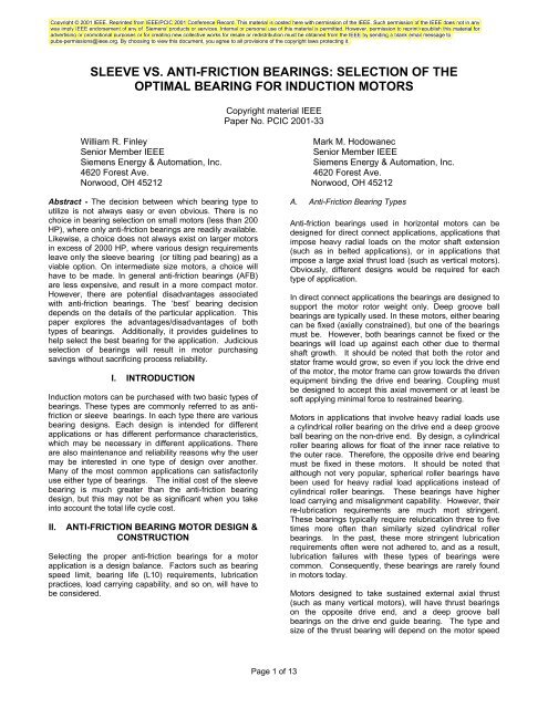
machines or in high ambient temperature areas byauxiliary oil supplied to the bearing by an external source,and drained from the oil sump back to the external source.The external source may be a motor-pump-cooler unit, oroften is pressurized supply, and drain lines, from thedriven equipment.G. Bearing TemperaturesThe total bearing temperature will be a function of the heatgenerated in the bearing, the heat absorbed by thebearing (caused by external and internal heat sources inproximity of the bearing), and the bearings ability to shedthe heat. Refer to the <strong>Sleeve</strong> Bearing Cooling section fordetails on how heat from the bearing is removed.<strong>Sleeve</strong> bearings by their very nature are heat-producingdevices. The rotating shaft journal is separated from thestationary bearing bushing only by an oil film. Consideringthat the oil adjacent to the shaft journal is moving at shaftjournal speed, while the oil adjacent to the stationarybearing bushing is stationary, it is apparent that the oilbetween the two surfaces is being sheared at a very highrate. Shearing of oil requires force, which in a time periodequates to power, which being entirely absorbed in thebearing, equates to heat. A three-inch bearing journal, ina 3600-rpm motor, has a surface speed of 2826 ft/mm.The minimum oil film thickness between the rotatingjournal and stationary bearing will vary from approximately0.0025 in a cool bearing to 0.0008 in a warm bearing,which is operating near 85 o C. The shearing action of theoil thus takes considerable energy.Although sleeve bearings produce a significant amount ofheat the biggest variable on bearing temperature isambient temperature and motor load. Assuming a 40 o Cambient temperature, the only remaining heat generationvariable is simply the motor load. Correlation betweenmotor load and bearing temperature will vary from onemotor design to another. Fig. 8 shows the dependence onbearing temperature for a particular motor design.There are two concerns in exceeding designtemperatures. First of all, the oil viscosity is strongly afunction of temperature. If the heat becomes excessivethan minimum oil film thickness will not be maintained.This could accelerate wear. Additionally, as the oil filmthickness changes significantly, the rotor-dynamicperformance may be affected. Secondly, the oil itself willbreak down faster at elevated temperatures, requiringmore frequent oil change intervals. In extreme cases, theoil itself can start to coke. The bearing babbit material alsohas temperature limits. Absolute bearing temperaturelimits vary from one motor manufacturer to another. Thistemperature limit will vary based on how the temperatureis being measured. This will be discussed in greater detailin the following subsection, Bearing TemperatureDetection. API 541 limits bearing temperature to 93Cabsolute temperature.H. Bearing Temperature DetectionBearing temperatures may be detected by monitoring thesump temperature, or by monitoring the bearing metaltemperature. The bearing metal temperature may bedetected by means of embedded detector or by a bayonettype of detector. The embedded detector can usually beplaced closer to the bearing surface than the bayonetdetector. Fig. 9 illustrates both types.When detecting bearing metal temperature, the loadedportion of the bearing must be monitored. Both types ofbearing detectors in Fig. 9 are shown in this orientation.Bearing detectors can be either thermocouples orresistance temperature devices (RTD’s).2 POLE 5812 BEARING TEMPERATURE RISE5048Bearing Rise Extrapolated to 40 C Ambient (C)46444240383634Drive BearingNon DriveBayonet Type TemperatureDetector323020 25 30 35 40 45 50 55 60 65 70 75 80Stator Rise By RTD (C)Fig. 9 Bearing Temperature Detection DevicesFig. 8 bearing temperature as Function of StatorTemperature for one particular MotorI. Vibration MonitoringIdeally, in sleeve bearing motors shaft vibration andhousing vibration would be obtained. In anti-frictionPage 7 of 13
earing motors, housing vibration data is sufficientbecause the bearing is sufficiently stiff and has lowenough damping properties that any movement in theshaft will be transmitted to the housing. In sleeve bearingmachines this is not the case. Because of the largerbearing clearance, lower (and asymmetric) stiffnesscharacteristic, and a high degree of damping, it is possibleto have significant movement in the shaft that would no bedetected at the bearing housing.J. Speed LimitAlthough sleeve bearings do have speed limits, they arevery high. Depending on the sleeve bearing type,peripheral speeds up to 492 ft/sec are obtainable [2]. As areference, a 3600-RPM motor with a 4.5” journal diameterhas a peripheral speed of 71 ft/sec!K. <strong>Sleeve</strong> Bearing Life<strong>Sleeve</strong> bearings are theoretically considered to have aninfinite life, and, when properly maintained the life may beextremely long. The only time that a properly maintainedsleeve bearing should get any significant wear is atprolonged low speed operation. During low speedoperation the oil film will not be at its desired thicknessand subsequently, increased bearing wear results. Atstandstill, the oil film thickness is zero. Such conditionsmay be encountered during extended startup or coastdown periods. If the frequency of such events is oftenenough, hydrostatic jacking is recommended to minimizebearing wear. Hydrostatic jacking is where the shaftjournal is lifted off the bearing by oil pressure from thelower part of the bearing before the shaft begins to turn,thus ensuring adequate film thickness at extremely lowspeeds (down to zero speed). Hydrostatic jackingrequires special sleeve bearings and an oil pressurizationsystem and is normally only available on very largemachines.L. Load CapabilityMotor sleeve bearings are not intended for use inapplications where there is either side loading or axialloading. In regards to side loading, cylindrical sleevebearings are only intended to take the weight of the rotorin the nearly vertical direction. In side loading (i.e.horizontal loading) there would be no oil film wedgedeveloped to maintain the proper separation between thejournal and the bearing. Tilting pad bearings are moretolerant of side loading.As far as axial loading is concerned, there is normally anaxial babbitted surface. In most sleeve bearings designedfor horizontal application, the axial surface is designed totolerate only momentary axial loading as could be seen onstart up. A sufficient oil film is never developed; therefore,sustained axial loading is not permissible. Some sleevebearings are designed to take continuous axial load butbecause of the greatly reduced surface area, the axialload capability is very slight. <strong>Sleeve</strong> bearings are sosensitive in this regard (i.e. axial thrusting), thatmaintaining level motors is extremely important. A motorthat is not level can axially load the bearing if the couplingis incapable of holding the rotor in place.M. <strong>Sleeve</strong> Bearing CoolingThe heat generated at the bearing surface is removedthrough oil being supplied to and flowing through theloaded bearing surface. This oil then conducts away theheat. Three methods are in common usage: self cooledbearings, force feed lubrication, and water cooling.In self-cooled bearings the heat in the oil sump istransmitted to the bearing housing, which itself is cooledby external airflow around the externally finned surfaces.This is always the first choice of cooling methods, butoftentimes more heat is generated/absorbed by thebearing than what a self-cooled bearing can get rid of. Ifthat is the case, one of the other two mechanisms must beemployed.In force feed lubrication systems the oil is taken out of thebearing housing. There is a bearing sump, but the keyhere is that the oil itself is cooled before it returns to thebearing. See the Flood (or Force Fed) Lubricationsubsection for additional details.Water-cooled bearings simply imply that a cooling coil isinserted in the oil sump. Cool water is run through thecooler thus removing heat from the oil.N. <strong>Sleeve</strong> Bearing Construction<strong>Sleeve</strong> bearing motors are inherently more complex thananti-friction bearing motors, requiring many morecomponents. See Fig. 10.• Bearing• Oil Rings• Capsule• Inner and outer Oil Seals• Inner air seal• Atmospheric Vent (Built Into Oil guard &/orCapsule)• Internal Pressure Lines and Chamber(Depending on machine size and speed) NotShownThe bracket holds the capsule to the motor frame (yoke).The capsule may contain the oil seals, or the oil seals maybe a separately bolted on part. Then inside the capsuleyou have the bearing itself. The bearing normally comeswith 1 or 2 oil rings, which pick up the oil from the reservoirand dispense it on the shaft as the oil ring rides up againstit. This is shown in Fig. 7.The sleeve bearing itself must be constructed in such afashion that the bearing bushing is self-aligning during theassembly process. If proper alignment is not set up, thenit will be impossible to achieve a correct wear pattern. Thewear pattern is the wear marks that a rotating shaft leaveson the bearing before an oil film is established. An even,centered pattern with at least 85% contact is desirable.Page 8 of 13
AirSealVent ChamberA. Anti-Friction Bearing: Re-Lubrication& Lack of LubricationProper lubrication is critical with all bearings but it is muchmore important with anti-friction bearings. The primaryreason is that anti-friction bearings give little prior noticebefore catastrophic failure.BearingHousingBearingOilSealOilRingCapsuleOil sump and oil mist lubrication is very reliable. <strong>Bearings</strong>thus lubricated generally achieve their calculated life.However, it is generally much more difficult to properlymaintain grease lubricated bearings, which are by far themost common. There are many reasons why greaselubrication may not be as reliable. There are concerns withover-lubrication, under-lubrication, re-greasing withincompatible grease, and lack of cleanliness during relubrication,just to name a few.O. Shaft (Oil) SealsFig. 10 <strong>Sleeve</strong> Bearing ArrangementIn sleeve bearings, shaft seals are normally referred to asoil seals. This is because their primary function is to keepthe oil from escaping. Recall that the primary purpose ofanti-friction bearing shaft seals is to keep contaminationout off the bearings. The primary purpose of sleevebearing shaft seals (i.e. oil seals) is to keep the oil in. Oilseals are required on both sides of the bearing (internaland external to the motor). On some motors (such as openmachines) there may be suction internal to the machine,trying to suck the oil into the motor’s rotor. Many times thevacuum/pressure is great enough that the labyrinth sealalone is not enough to prevent oil leaks. In these casesthere is an external air intake present between thelabyrinth seals. In larger/faster motors even this may notbe enough. In some larger high-speed machines anotherchamber will be added which the internal fans pressurize.The oil seals are critical to the design. There are severaltypes of oils seals in common usage: rigid labyrinth,floating labyrinth, and baffle seal. In addition, some of theseals as described in the anti-friction bearing section maybe employed for additional protection from contaminants.Oftentimes several oil seals are used in conjunction withone another to form a sealing system.On rigid and floating labyrinths, it is important to maintaina tight fit to the shaft but so tight that they will rub. Oilseals can be made out of aluminum, bronze or nonmetallicmaterials such as but not limited to Torlon, Teflonor Peak.IV. MAINTAINABILITY & RELIABILITYIn this section both sleeve bearings and anti-frictionbearings will be addressed. Obviously, some issues areonly of concern to one of the bearing constructions,Contamination will shorten the bearing life significantly.Particular if the contaminant is harder than the bearingmetals.Under-lubrication will result in increased metal-to-metalcontact and increased bearing contact stresses. This willresult in severely shortened bearing life.Regreasing the bearings with incompatible greasetypically causes the resultant grease mixture to be muchsofter. Soft enough in many cases to let the lubricantstotally run out of the bearing. Once this happens then thebearing fails from under-lubrication. It is always safest tore-grease bearings with the same grease that’s already inthem. If this is not possible, the degree ofcompatibility/incompatibility needs to be determined. Thiscan only be conducted by the grease manufacturers. Ifthe greases are at all incompatible, then they cannot beintermixed.Over lubrication will cause the bearing to run hotter,especially if the bearing cavity has no empty space in thehousing in which to dispose of the excess grease. A 20-30degree C increase in bearing temperatures can cause thebearing to over heat and go into a runaway condition.Over-lubrication can be a serious problem particularly inhigh-speed motors. High speed is relative to bearing sizeand type. A good measure of ‘high speed’ is how closethe bearing speed is to its grease-lubricated speed limit.For example, a 6218 deep groove ball bearing has agrease lubricated maximum speed of 3800 RPM. A 6232deep groove ball bearing has a grease lubricatedmaximum speed of 1900 RPM. The 6218 bearing at 3600RPM is at the same risk of failure due to over-lubricated asa 6232 bearing at 1800 RPM. An over-lubricated bearingtakes many hours for the excess grease to purge itself out.The temperatures may exceed the bearing heatstabilization temperature, thus ruining the bearing andcausing it to fail prematurelyPage 9 of 13
6.3 <strong>Inc</strong>h25 O CAmbient40 O c40 O C Brg HousingFig. 11 – Thermal network A/F BrgB. <strong>Sleeve</strong> Bearing: Re-Lubrication & Lack of LubricationProper lubrication is important for any bearing type.However, sleeve bearings are more tolerant of lubricantabuse than anti-friction bearings. If the lubrication is nonoptimal,than the sleeve bearing will give better warningthan anti-friction bearings would, especially if the bearingsare equipped with bearing temperature detectors.<strong>Sleeve</strong> bearings are lubricated with high-grade turbine oil.It is important to use the proper viscosity oil. If a differentviscosity is used than what the bearings were designedfor, than several things may occur: inferior rotor-dynamicperformance, change in bearing oil film thickness, orincrease in bearing heating.Unless otherwise stated, it is assumed that this oil ismineral based. Synthetic oils are becoming morecommon, but their compatibility with paint and sealingsystems must be verified. Non-compatible oils will bechemically aggressive to the paint and sealing systemscausing leaks and foreign material getting into the bearing.Catastrophic failure may result!The oil must be maintained at the proper level. Properlevel is indicated by having the oil level centered on thebull’s eye or to the appropriate mark on a sight glass/gage.Additionally, constant level oilers can be used to assureproper oil level on sleeve bearing motors.The variation allowance in the oil level should be kept ata minimum. If the level is too high it can leak out, or slowthe oil ring down to the point that it is incapable ofdelivering the required oil to the shaft journal/bearing. If itis more than ¼ in low it can cause failure. Refer to OilRing subsection for additional details.C. Notification of Imminent Failure2.95 <strong>Inc</strong>h60 O C ShaftTemperature50 O C Bearing<strong>Sleeve</strong> bearings are more likely to give you a warningimminent failure than anti-friction type bearings. Manytimes sleeve bearings will begin to wipe under highvibration conditions and while this is happening RTD willshow some higher temperature levels and then return tonormal, but when you open up the machine you will seeheavy wear patterns and bearing wiping. Also when<strong>Sleeve</strong> bearings begin to fail babbit material will begin tocontaminate the oil causing it to turn black. Thisdiscoloration can also be seen when shaft currents exist.Anti-friction bearings on the other hand can fail ratherquickly with little to no warning. Many cases have beennoted where the operator walked past a motor when it wasrunning very well and moments later the bearings failedcatastrophically causing the rotor to hit the stator resultingin total destruction of the motor.One scenario is quite possible. When for any reason thebearing begins to run hotter than the bearing housing theclearance in the bearing (which can be as low as one ortwo mils on anti-friction bearings) can quickly be used up. .Fig. 11 shows the typical temperatures that can be seenon open motors with ambient air on both sides of thebearing. A 6.3-inch OD bearing that has a 10 degree Crise above the bearing housing temperature will expand1.12 mils per inch for every 100 deg C. For this 6.3-inchbearing that would be .71 mils for every 10 O C. Thediametrical clearance between the bearing and thehousing ranges from 0-2 mils. The bearing internalclearance ranges from 1-2 mils. This would result in a totalaverage clearance of 2.5 mils. If the differentialtemperature between the housing and the bearing in thisexample were 35 O C the clearance would be used up.Above that the bearing would be damaged. The bearingwould then be subjected to extreme compressive stressesas the bearing starts pushing against itself, the shaft, andthe bearing housing. Initially the tighter clearances mayactually result with the motor running with less vibration.But once this process begins, a thermal runaway conditionwill follow. Eventually, the outer race will expand to thepoint of locking in the bearing housing. The inner raceexpands and begins to spin on the shaft and the balls getimbedded in the inner and outer race. At this point thebearing has catastrophically failed. If the motor is not shutdown very quickly the rotor can quickly hit the statorcausing extensive and very expensive damage.Another condition that may exist is axial loading betweenbearings. When the rotor assembly and shaft heats up andexpands axially, the bearing, which is intended to float inthe housing, could possibly, due to excessive heat,expand radially to a point where it could seize in thehousing not permitting axial growth. This would result inexcessive axial loading of both bearings. This failure modewill look like excessive thrust loading.D. Bearing ReplacementIt is not possible to replace anti-friction bearings withoutremoving the bearing housings and uncoupling the drivenequipment. Then a significant amount of access room isstill required for the necessary equipment to remove theold bearings. In general the motor must be removed forbearing replacement.<strong>Sleeve</strong> bearings, on the other hand, can be replaced withthe lower bearing housings intact and driven equipmentPage 10 of 13
coupled. This can be a significant feature if riggingrequirements make it extremely difficult to remove themotor.Anti-friction bearings failures tend to be catastrophic innature, oftentimes providing little prior warning. In somecases the bearings fail to the point of having the rotor dropdown into the stator, essentially destroying the entiremotor. Even if the entire motor is not damaged, the shaft(and thus rotor assembly) must oftentimes be replacedafter a catastrophic bearing failure, as the inner race tendsto first spin and later weld itself to the shaft.When sleeve bearings fail, they tend to be lesscatastrophic, and generally provide information as to thedegrading state of the bearings. When the bearings failcatastrophically, the bearing itself tends to be sacrificial,as the bearing babbit is much softer than the shaft steel.Generally it is possible to clean up the shaft with minorregrinding of the bearing journal surface.V. PERFORMENCEA. Efficiency <strong>vs</strong>. Bearing TypeIt is sometime asked whether anti-friction bearings canachieve better efficiency than sleeve bearing machines. Ingeneral the answer is that the difference is insignificant..A/F bearings do normally generate fewer losses butnormally the losses are a small percentage of the totallosses having little effect on the total efficiency. Regardingthis question, the following example for a 500 frame 2 pole300 HP and 1250 HP motor may help:Total. Brg. Efficiency .Loss Loss A/F <strong>Sleeve</strong>W/O in kW Brg. BrgHP Brg. A-F / <strong>Sleeve</strong>.. Loss .300 13.5 .52/ .75 94.09 94.001250 46.7 .52/ .75 95.17 95.15As can be seen from the above, the difference is small.B. Service life <strong>vs</strong>. Theoretical lifeThe calculated life expectancy of any bearing is based onfour assumptions.1) Good lubrication in proper quantity will always beavailable to the bearing.2) The bearing will be mounted without damage.3) Dimensions of parts related to the bearing will becorrect.4) There are no defects inherent in the bearing.In general, sleeve bearings have an extremely long life.Anti-friction bearings that are oil mist or sump lubricatedalso do and will reach their expected L10 fife. Greaselubricated bearing rarely reaches their expected L10 life.C. Rotor-Dynamic PerformanceBearing selection can have a significant impact on rotordynamic performance. Table III shows the results of acase study of a similar motor with different bearings. Therotor under study was for a 3600 RPM 1250 Horsepoweropen motor. The rotors were similar, with the obviousexception of bearings (and the required subsequentchanges in the shaft).Notice that as the stiffness decreases, so does theresonant frequency. However, highly damped resonancesare not considered to be critical speeds. Per API 684,amplification factor is defined as a measure of a rotorbearingsystems vibration sensitivity when operated in thevicinity of one of its lateral critical speed [3]. Furthermore,this same standard defines critical speed as a shaftrotational speed that corresponds to a non-criticallydamped (amplification factor >2.5) rotor system resonancefrequency. This is an important definition as a highlydamped resonance should not be misinterpreted as acritical speed. The justification in this lies in the fact thateven if a motor were to operate right at this speed, theincrease in vibratory response would be so low that nodamage to the motor or bearings would occur. This isevident when reviewing the calculated rotor dynamicperformance of the 150 Partial arc sleeve bearing to the6315 anti-friction bearing, in particular, with respect to therotor response to unbalance as illustrated in Fig. 11:Fig. 11 compared the predicted increases in vibration dueto an unbalance of 4W/N, which is equal to the residualunbalance limit for each end of the rotor in API 541motors. The peak to the right corresponds to the 6315AFB bearing, and the peak to the left, the 150 degreepartial arc bearing. Note the significantly different scalesfor the two curves (6315 corresponds to the scale on theright, and the 150 degree partial arc, the scale to the left).Furthermore, note that the vibration of the 6315 rotorwould be 34 times higher at its resonant speed comparedto operating speed. Clearly, vibration severity of thismagnitude cannot be tolerated for any period of time.150 <strong>Sleeve</strong> BearingVibration mils Pk-Pk0.30.250.20.150.10.05010001500Rotor Response to Unbalance (4W/N)2000250030003500400045005000Rotor Speed - RPMFig. 11 Rotor response to unbalance550060006500700032.521.510.506315 AFB Vibrationmils Pk-PkLikewise, the 150-degree partial arc-bearing rotor wouldbe 1.2 times higher at its resonant speed compared tooperating speed. The rotor can operate at this speedindefinitely without any harm to the rotor or bearing.Page 11 of 13
TABLE IIIROTOR RESPONSE OF DIFFERENT BEARNGSStiffness (lbs./in. *10^6)Oil Viscosity Vertical Horizontal Resonant Freq. (CPM) Amp.Brg. Type ISO VG Hsg. Brg. Hsg. Brg. Vert. Horiz. Factor120 Partial Arc 32 1.0 0.564 0.5 0.215 5000 2800 2.56150 Partial Arc 32 1.0 0.467 0.5 0.251 5000 3100 2.21Four Lobe Tilt Pad 32 1.0 0.673 0.5 0.673 4900 4200 5.286315 (AFB) 100 1.0 1.000 0.5 1.000 5000 4900 36.9In the past, rotor dynamic performance used to beconsidered only at the operating speed. The same is truetoday. However, today the operating speed no longer canbe assumed to be a fixed speed. With the advent (andincreasing popularity) of adjustable speed drives,operating speed ranges are becoming the norm. All rotorswill have a resonance somewhere. From a rotor dynamicperspective, the location of the horizontal and verticalresonance along with their associated amplification factorswill have to be carefully evaluated to make sure that therotor will perform adequately throughout its entireoperating range.D. External Load Carrying CapabilityAs stated throughout this paper, sleeve bearings aredesigned to support only the motor rotor weight. <strong>Antifriction</strong>bearing motors can be designed to acceptsignificant external load (radial and axial). From thatperspective, anti-friction bearings are more versatile.E. End playMotors with anti-friction bearings will have self-locatingrotors. Since one of the bearings is held in these motors,they are not reliant on the coupling for proper rotorpositioning. The same is not true of sleeve bearingmotors. <strong>Sleeve</strong> bearing motors require coupling thateither position the rotor, or, limited end float couplings.The limited end float coupling must have an allowablemovement not in excess of 3/16”. This will assure that themotor shaft does not move such that the journal shaftcontacts the bearing. Design clearances for the drive endand opposite drive end bearing and the coupling is shownin Fig. 12. In applications using sleeve bearings the drivenequipment must be capable of withstanding a slightoscillating thrust developed in the induction motor due toslight magnetic variations. The motor itself will not be ableto restrain the movement and the movement doesn’tbother the motor.F. CostAlthough cost is not a traditional performance measure, itis difficult to consider other performance aspects withoutalso considering cost. <strong>Sleeve</strong> bearing motors aresignificantly more expensive. Additionally, the vibrationmonitoring equipment is much more expensive. Fullvibration instrumentation for sleeve bearings motorsincludes proximity probes and accelerometers. Fullvibration instrumentation for anti-friction bearing motorsneeds just the accelerometers. Proximeter probes aremuch more expensive than accelerometers. The costcomparison in Fig. 13 is shown as a percentage of motorcost.The top curve represents the increase in motor cost overthe base price for addition of Proximeter probes. The nextcurve represents the increase in cost over base motor costfor sleeve bearings (instead of anti-friction bearing). Thefinal curve represents the increase in motor cost over baseprice for accelerometers.Cost <strong>Inc</strong>rease Over Base Motor Cost60%Proximeter ProbesMinimum LimitedMotor Coupling A B C1/2” 3/16” 3/32 5/32 11/32Fig. 12 <strong>Sleeve</strong> Bearing Motor with Limited End floatCoupling% of Base Motor Cost40%<strong>Sleeve</strong> <strong>Bearings</strong>Accelerometer Probes20%0%200 800 1400 2000HorsePowerFig. 13 Cost Vs. HP for FeaturesPage 12 of 13
VI.COMPARISONObviously, both types of bearings have their place. Bothbearing constructions have their advantages anddisadvantages. Table IV in a very simplistic form listssome of the advantages/disadvantages:TABLE IVBEARING SELECTION CHART1. Long Life <strong>Sleeve</strong>2. Availability A-F3. Maintenance <strong>Sleeve</strong>4. Bearing Replacement <strong>Sleeve</strong>5. Quietness <strong>Sleeve</strong>6. Application Flexibility A-F7. Thrust Load A-F8. Belt Drive A-F9. Prior Indication of Failure <strong>Sleeve</strong>10. Compactness A-F11. Cost A-Fcurrently active in over 10 NEMA and IEC working groupsand Sub-committees. He is Chairman of the LargeMachine Group and International Standardization Group ofNEMA.Mark M. Hodowanec received a B.S. and M.S. degree inmechanical engineering from the University of Akron,Akron, OH. Currently, he is the Manager of MechanicalEngineering for ANEMA induction motors built in the U.S.at <strong>Siemens</strong> Energy and Automation, <strong>Inc</strong>., Cincinnati, OH.For the past ten years he has worked in a variety ofengineering positions including design, productdevelopment, order processing, shop testing, and fieldsupport. He is currently active on various NEMA, IEEE,and API working groups. In addition to his ANEMA motorexperience, Mr. Hodowanec has worked on a wideassortment of induction motors such as NEMA,submersible, and MSHA motors. He is the author ofnumerous published technical articles.Unfortunately, the actual selection is somewhatcomplicated. Also once the type of bearing is chosen themethod of lubrication must be established. Within thesame application and comparing the same feature orcharacteristic, arguments can be made for either case.Complicating all of this is the fact that many of thesupposed advantages and disadvantages are subjectivelybased. Some things are just difficult to quantify.Hopefully the reader now has a better understanding ofmotor bearing design, construction, and maintenance.Weighing all of these factors, a well-informed decision cannow be made.VII.REFERENCES[1] “SKF General Catalog”, 4000 US, SKF 1991[2] “Manual for the Application of RENK Slide <strong>Bearings</strong>”,Renk Aktiengesellschaft[3] API Publication 684, First Edition, Tutorial on the APIStandard Paragraphs Covering Rotor Dynamics andBalancing: An Introduction to Lateral Critical and TrainTorsional Analysis and Rotor Balancing, Washington,D.C., 1996[4] NEMA Standards Publication No. MG 1-1993Rosslyn, VA, 1996VIII.VITAWilliam R. Finley received his BS Degree in ElectricalEngineering from the University of Cincinnati, Cincinnati,OH. Presently, as Manager of Engineering for <strong>Siemens</strong>Energy & Automation, Bill is responsible for Above NEMAInduction Motor designs. Over the many years in thebusiness he has worked in various Engineering Designand management positions, including Electrical andMechanical Design, Product Development, Quotation andComputer Systems. He is a Senior member of IEEE andhas previously published 12 technical articles. He isPage 13 of 13