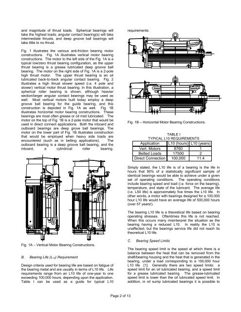
and magnitude of thrust loads. Spherical bearings willtake the highest loads, angular contact bearing(s) will takeintermediate thrusts, and deep groove ball bearings willtake little to no thrust.Fig. 1 illustrates the various anti-friction bearing motorconstructions. Fig. 1A illustrates vertical motor bearingconstructions. The motor to the left side of the Fig. 1A is atypical low/zero thrust bearing configuration, as the upperthrust bearing is a grease lubricated deep groove ballbearing. The motor on the right side of Fig. 1A is a 2-polehigh thrust motor. The upper thrust bearing is an oillubricated back-to-back angular contact bearing. Fig. 2illustrates a high thrust slower speed (i.e. 4 pole andslower) vertical motor thrust bearing. In this illustration, aspherical roller bearing is shown, although heaviersection/larger angular contact bearings may be used aswell. Most vertical motors built today employ a deepgroove ball bearing for the guide bearing, and thisconstruction is depicted in Fig. 1A as well. Fig. 1Billustrates horizontal motor bearing constructions. Thesebearings are most often grease or oil mist lubricated. Themotor on the top of Fig. 1B is a 2-pole motor that would beused in direct connect applications. Both the inboard andoutboard bearings are deep grove ball bearings. Themotor on the lower part of Fig. 1B illustrates constructionthat would be employed when heavy side loads areencountered (such as in belting applications). Theoutboard bearing is a deep groove ball bearing, and theinboard, a cylindrical roller bearing.requirements:Fig. 1B – Horizontal Motor Bearing Constructions.TABLE ITYPICAL L10 REQUIREMENTSApplication L10 (hours) L10 (years)Vert. Motors 8760 1Belted Loads 17500 2Direct Connection 100,000 11.4Simply stated, the L10 life is of a bearing is the life inhours that 90% of a statistically significant sample ofidentical bearings would be able to achieve under a givenset of operating conditions. The operating conditionsinclude bearing speed and load (i.e. force on the bearing),temperature, and state of the lubricant. The average life(i.e. L50 life) is approximately five times the L10 life. Inother words, a motor with bearings designed for a 100,000hour L10 life would have an average life of 500,000 hours(over 57 years!).The bearing L10 life is a theoretical life based on bearingoperating stresses. Oftentimes this life is not reached.When this occurs many misinterpret the situation as thebearing having a reduced L10. In reality the L10 isunaffected, but the bearings service life did not reach itstheoretical L10 life.Fig. 1A – Vertical Motor Bearing Constructions.B. Bearing Life (L 10 ) RequirementDesign criteria used for bearing life are based on fatigue ofthe bearing metal and are usually in terms of L10 life. Liferequirements range from an L10 life of one-year to oneexceeding 100,000 hours, depending upon the application.Table I can be used as a guide for typical L10C. Bearing Speed LimitsThe bearing speed limit is the speed at which there is abalance between the heat that can be removed from theshaft/bearing housing and the heat that is generated in thebearing, under a load corresponding to a 150,000 hourL10 life [1]. Generally there are two speed limits: aspeed limit for an oil lubricated bearing, and a speed limitfor a grease lubricated bearing. The grease-lubricatedspeed limit is lower than the oil lubricated speed limit. Inaddition, in oil sump lubricated bearings it is possible toPage 2 of 13
cool the oil such the bearing speed limit can be safelyincreased.The highest horsepower rating in which anti-frictionbearings can be used is indirectly limited by the bearingspeed limit. As larger horsepower ratings areencountered, larger shaft sizes will have to be used tokeep torsional shaft stresses within acceptable levels.However, as shaft size (and thus bearing size) goes up,the bearing speed limit goes down. Eventually therequired shaft size will result in anti-friction bearings thathave a lower bearing speed limit than the motoroperational speed. At this point a sleeve bearing would berequired.Table II can be referenced as a guide for typical speedlimits for various ratings and applications [1]:TABLE IITYPICAL APPLICATION & SPEED LIMITSGreaseFrame HP Speed Application DE Brg Spd. Lim.320 50 3600 DC 6312 5000580 2000 3600 DC 6315 4300580 1500 1800 Belted NU2228 2000680 4000 1800 DC 6232 1900800 5000 1200 DC 6334 1700D. Bearing Housing and Shaft FitsBearing manufacturers provide recommendations forbearing housing and shaft fits. In general, the rotatinginner ring should have an interference fit on the shaft, andthe non-rotating outer ring, a slight clearance in thehousing. Although the bearing manufacturers providerecommendations, it is up the motor manufacturers totemper this information and determine what fits work best.Ideally, the fit with a clearance should be as loose aspossible without sacrificing vibration performance.E. Anti-Friction Bearing TemperaturesBearing temperatures vary a great deal depending onmotor design and speed. On open horizontal machines,which are identical on both ends, the bearingtemperatures on both ends of the motor will be similar. Ontotally enclosed fan cooled (TEFC) motors, the non-driveend bearing is much cooler than the drive end bearing dueto increased cooling. Most anti-friction bearings them selfhave temperature limits of 150 Deg. C (300 F) thoughtthey normally will never be allowed to run that warm. Ifthis temperature is exceeded than permanent bearingdamage may result. It is possible to get bearings that areheat stabilized to a much higher temperatures. However,bearing lubrication requirements at these highertemperatures will have to be reviewed to make sure thatthe bearing is properly lubricated at these elevatedtemperatures. The motor manufacturer can providemaximum safe bearing operating temperature taking allthese factors into account.F. Bearing Temperature DetectionThe most common method of bearing temperaturedetection is thru measurement of the outer racetemperature by a Resistance Temperature Device (RTD).This measurement of outer race temperature will providegood indication of overall bearing temperature. <strong>Antifriction</strong>bearings can fail quickly, without much priorwarning. The true benefit of temperature detection iswhen used in a trending fashion. Any unexplainablechange in bearing temperature should be thoroughlyinvestigated.G. Bearing Vibration DetectionThe most common method of bearing vibration detectionis thru measurement of bearing housing vibration. Aseismic vibration transducer (i.e. accelerometer) is mostcommonly used, and the most common units for this typeof measurement is in velocity in inches per second. It isimportant to understand the difference between RMS andpeak. Normally in the United States the velocitymeasurement is taken and expressed in inches persecond (ips) peak value. European convention is RMS(root mean square value of peak) expressed in mm persecond (mm/s). A common error is to/from convert fromips to mm/s neglecting the peak <strong>vs</strong>. RMS conversion.H. Anti-Friction Bearing LubricationIn addition to choosing the type of bearing to use one mostalso choose the type of lubrication and type of bearingcavity (cleanliness) protection. Anti-friction bearings aretypically lubricated by one of three methods: greaselubrication, oil mist lubrication, and oil sump lubrication.Motors with grease-lubricated bearings have the lowestinitial cost (compared to other anti-friction bearinglubrication methods). They however require the mostmaintenance. Additionally, this method is the mostproblematic. Over-lubrication, under-lubrication and lackof cleanliness during re-lubrication are common problemsthat impact not only cost, but motor reliability as well.Motors with oil mist lubricated bearings have very similarconstruction to motors with grease lubrication. As long asthe oil mist system is correctly set up and workingproperly, the bearings are always assured a clean supplyof lubricating oil. Although initial cost is higher, in manycases the life cycle cost is lower as the maintenancerequirements are much less. In addition, the motors seemuch greater reliability and increased mean time betweenfailures.Oil sump lubrication is usually employed when thebearings need additional cooling than what can be offeredby grease or oil mist lubrication. Typically only verticalmotors use this type of lubrication arrangement. A coolingcoil is often submersed in the oil for additional cooling.Fig. 2 illustrates such an arrangement.Page 3 of 13