Remote Control System through Mobile and DTMF
International Journal of Computational Engineering Research(IJCER) is an intentional online Journal in English monthly publishing journal. This Journal publish original research work that contributes significantly to further the scientific knowledge in engineering and Technology.
International Journal of Computational Engineering Research(IJCER) is an intentional online Journal in English monthly publishing journal. This Journal publish original research work that contributes significantly to further the scientific knowledge in engineering and Technology.

Create successful ePaper yourself
Turn your PDF publications into a flip-book with our unique Google optimized e-Paper software.
International Journal of Computational Engineering Research||Vol, 03||Issue, 8||<br />
<strong>Remote</strong> <strong>Control</strong> <strong>System</strong> <strong>through</strong> <strong>Mobile</strong> <strong>and</strong> <strong>DTMF</strong><br />
Abdiweli Abdillahi Soufi 1, Abdirasoul Jabar Alzubaidi 2<br />
1 Information Technology College, Open University of Sudan.<br />
2 Electronics Engineering School, Sudan University of Science <strong>and</strong> Technology<br />
ABSTRACT:<br />
This paper proposes a control system which enables controlling remotely <strong>through</strong> mobile<br />
phone <strong>and</strong> <strong>DTMF</strong> decoder. The system will control a cutter machine in foam processing factory. The<br />
proposed system will take remote control process over mobile network. In this system a mobile phone<br />
sends controlling signal from remote location. 3.75G internet modem is used to receive the signal from<br />
the mobile <strong>and</strong> transmits the signal to <strong>DTMF</strong> decoder <strong>through</strong> computer headphone, <strong>DTMF</strong> 8870<br />
decoder is used to decode the tone generated by the buttons of the mobile keypad. PC computer hosts<br />
software for controlling cutter machine, latching IC in the system is for signal buffering <strong>and</strong><br />
Darlington IC for signal amplifying. The proposed system provides solution for industrial sector to<br />
access <strong>and</strong> control devices <strong>and</strong> machines remotely.<br />
KEYWORDS: <strong>Control</strong>ling signal, Cutter Machine, <strong>DTMF</strong> Decoder, Internet Modem, Latching IC,<br />
<strong>Mobile</strong> Phone, PC computer, <strong>and</strong> Signal tone.<br />
I. INTRODUCTION<br />
<strong>Remote</strong> <strong>Control</strong> <strong>System</strong> is a control system that allows accessing <strong>and</strong> managing an electrical or<br />
electronic device remotely [2]. <strong>Remote</strong> control systems are used in different fields like home management,<br />
factory automation, space exploration, robot operating, <strong>and</strong> other critical fields [1,5]. There are many advantages<br />
of using remote control systems; remote control systems are great time <strong>and</strong> effort savers, also they provide<br />
flexibility, security, independence of location or geographical distance.<br />
This paper proposes a method to control remote machine using mobile <strong>and</strong> <strong>DTMF</strong> decoder. The<br />
proposed system will take remote control process over mobile network to control a cutter machine, without<br />
regarding the phone model <strong>and</strong> mobile phone carrier. Using mobile networks in remote control system has<br />
following characteristics: Reliable <strong>and</strong> resilient, immune to interference from other radio sources, data <strong>and</strong><br />
internet oriented, broadb<strong>and</strong> capability, <strong>and</strong> wider coverage [7]. This system uses a mobile phone <strong>and</strong> internet<br />
modem. PC computer is a central unit for the system which hosts software program to manage controlling<br />
process. Many proposed systems for remote controlling uses two mobiles to send <strong>and</strong> receive controlling signal<br />
from the user to the side where controlled device is allocated. In this system a mobile phone <strong>and</strong> 3.75G internet<br />
modem are used, the modem can receive call from the mobile, since the modem is used primarily for internet<br />
usage using controlling purpose can be useful. The proposed system will control cutting machine in form<br />
processing factory. The machine cuts foam blocks by rotating the blocks into different predesigned sizes. The<br />
system can carry following comm<strong>and</strong>s to control cutting machine; Turn-on/turn-off machine, change foam size<br />
to predesigned shapes (designs one, design two, etc.), Increase machine speed, decrease machine speed.<br />
<strong>DTMF</strong> Decoder<br />
II. SYSTEM COMPONENTS<br />
<strong>DTMF</strong> is short for Dual Tone Multi Frequency. It is a generic communication term for touch tone (a<br />
Registered Trademark of AT&T). The tones produced when dialing on the keypad on the phone could be used<br />
to represent the digits, <strong>and</strong> a separate tone is used for each digit. Pressing any key generate unique tone which<br />
consists of two different frequencies one each of higher <strong>and</strong> lower frequency range. The resultant tone is<br />
convolution of two frequencies [1,5,6]. Figure 1 shows mobile keypad frequencies <strong>and</strong> table1 also shows tone<br />
frequency associated with a particular key.<br />
||Issn 2250-3005 || ||August||2013|| Page 45
Figure 1 Phone keypad for <strong>DTMF</strong> generation [10]<br />
<strong>Remote</strong> <strong>Control</strong> <strong>System</strong> Through…<br />
Table1 Tone frequency associated with a particular key resulting<br />
Button Low<br />
Frequency<br />
High<br />
Frequency<br />
1 697 1209 1906<br />
2 697 1337 2034<br />
3 697 1477 2174<br />
4 770 1209 1979<br />
5 770 1337 2107<br />
6 770 1477 2247<br />
7 852 1209 2061<br />
8 852 1337 2189<br />
9 852 1477 2329<br />
0 941 1209 2150<br />
* 941 1337 2278<br />
# 941 1477 2418<br />
Key<br />
Frequency<br />
Each of these tones is composed of two pure sine waves of the low <strong>and</strong> high frequencies superimposed on each<br />
other. These two frequencies explicitly represent one of the digits on the telephone keypad. Thus generated<br />
signal can be expressed mathematically as follows:<br />
f ( t ) = AH sin( 2π fH t ) + AL sin( 2π fL t ) (1)<br />
Where AH, AL are the amplitudes & fH, fL are the frequencies of high & low frequency range. Properties of<br />
<strong>DTMF</strong> tone frequencies are:<br />
No frequency is an integer multiple of another<br />
The difference between any two frequencies does not equal any of the frequencies<br />
The sum of any two frequencies does not equal any of the frequencies<br />
1. Sudani One 3.75G Internet modem:<br />
Sudani One 3.75G Is a USB modem for wireless internet connections, based on 3.75G (HSDPA/HSUPA)<br />
technology with speeds up to 7.2 Mb/s to provide convenient <strong>and</strong> flexible Internet access, whether the user<br />
machine is PC computer , laptop, <strong>Mobile</strong> or any other device[8].<br />
Figure 2 Sudani One Modem[8]<br />
||Issn 2250-3005 || ||August||2013|| Page 46
<strong>Remote</strong> <strong>Control</strong> <strong>System</strong> Through…<br />
2. PC Computer:<br />
PC computer hosts developed software using C++ programming language to control cutting machine.<br />
The PC computer is connected with 8870 <strong>DTMF</strong> decoder via parallel port inputs. The software dictates the<br />
processor to h<strong>and</strong>le controlling process. A corresponding signal is then sent via the output pins of the parallel<br />
port to the HD74LS373 latch IC.<br />
3. HD74LS373 Latching IC:<br />
The HD74LS373 is eight bit is register IO mapped used as a buffer which stores signals for future use.<br />
Different types of latches are available HD74LS373 octal D-type transparent latch will be used in this system.<br />
This type of latch is suitable for driving high capacitive <strong>and</strong> impedance loads[12].<br />
4. ULN 2001A Darlington IC:<br />
The ULN2803A is a high-voltage, high-current Darlington transistor array. The device consists of eight<br />
NPN Darlington pairs that feature high-voltage outputs with common-cathode clamp diodes for switching<br />
inductive loads. The collector-current rating of each Darlington pair is 500 mA. The Darlington pairs may be<br />
connected in parallel for higher current capability[11].<br />
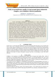
5. Cutting Machine:<br />
Cutting machine is an electrical machine used to cut raw blocks of exp<strong>and</strong>ed foam into predesigned shapes.<br />
The machine uses a type of tool known as a hot-wire foam cutter. The predesigned shapes are both manual <strong>and</strong><br />
fully automatic designs. The applied cutting machine cuts foam blocks by rotating the block.<br />
Figure 3 cutter Machine<br />
III. METHODOLOGY<br />
The main goal of the proposed system is to send controlling signal remotely from mobile phone to<br />
controlled machine using mobile network. The whole system can be divided into following stages:<br />
a. <strong>Mobile</strong> Phone Stage:<br />
A mobile phone is used to send controlling signal. The mobile user dials SIM card number in the<br />
Sudani One modem. After initiating the call, pressing particular button of mobile keyboard produces specific<br />
<strong>DTMF</strong> tone.<br />
b. Internet Modem Stage:<br />
Sudani One modem is used in this system but any other internet modem contains SIM card can be<br />
used. Sudani One modem is connected with PC computer <strong>through</strong> USB port. The modem is auto-receiving<br />
mode. The mobile <strong>and</strong> the modem are connected via mobile network by receiving call from the mobile. After<br />
receiving the control signal the modem transmits the signal to the PC <strong>through</strong>.<br />
c. 8870 <strong>DTMF</strong> Decoder Stage:<br />
The signal is fed to 8870 <strong>DTMF</strong> decoder chip <strong>through</strong> headphone connected with the PC computer. The<br />
<strong>DTMF</strong> decoder will give corresponding BCD value of tone as shown in table2. Each key press at transmitter<br />
end reflects as a BCD value of Q1, Q2, Q3, <strong>and</strong> Q4. The outputs of the <strong>DTMF</strong> decoder are sent to the PC<br />
<strong>through</strong> parallel port [5].<br />
||Issn 2250-3005 || ||August||2013|| Page 47
<strong>Remote</strong> <strong>Control</strong> <strong>System</strong> Through…<br />
Table2 8870 <strong>DTMF</strong> output truth table<br />
Button Low High TO Q4 Q3 Q2 Q1<br />
Frequency Frequency E<br />
1 697 1209 1 0 0 0 1<br />
2 697 1336 1 0 0 1 0<br />
3 697 1477 1 0 0 1 1<br />
4 770 1209 1 0 1 0 0<br />
5 770 1336 1 0 1 0 1<br />
6 770 1477 1 0 1 1 0<br />
7 852 1209 1 0 1 1 1<br />
8 852 1336 1 1 0 0 0<br />
9 852 1477 1 1 0 0 1<br />
0 841 1209 1 1 0 1 0<br />
* 841 1336 1 1 0 1 1<br />
# 841 1477 1 1 1 0 0<br />
0= LOGIC LOW, 1= LOGIC HIGH<br />
d. PC Computer Stage:<br />
The output signal from the 8870 <strong>DTMF</strong> decoder is fed to the computer via parallel port inputs. The<br />
software dictates the processor to make a sequential pulling for the parallel port control to check if any<br />
signal is available from input pins. The detected signal is h<strong>and</strong>led by the Micro-processes according to the<br />
instructions in the software. A corresponding signal is then sent via the output pins of the parallel port to the<br />
HD74LS373 latch IC.<br />
e. Latching Block Stage:<br />
The HD74LS373 is eight bit is register IO mapped <strong>and</strong> has unique address that work with parallel<br />
port. The signal received from the parallel port of the PC computer must be latched to be available to the<br />
interface to be controlled till a further change in the signal occurs.<br />
f. Darlington Pairs Block:<br />
The outputs of the latch pins are fed to the input pins of the ULN 2001A Darlington pair chip, this<br />
chip is the ideal solution for the interface between the low level logic circuitry <strong>and</strong> multiple peripheral<br />
power loads.<br />
IV. BLOCK DIAGRAM<br />
<strong>Remote</strong><br />
<strong>Mobile</strong><br />
Phone<br />
Cutting<br />
machine<br />
ULN 2001<br />
Darlington<br />
<strong>Mobile</strong> Internet USB<br />
Modem<br />
Network Port<br />
Headphone<br />
<strong>DTMF</strong> Decoder<br />
HD74LS<br />
373 3<br />
Interface Serial<br />
Port<br />
Figure 4 Block diagram<br />
PC<br />
Computer<br />
<strong>Control</strong>ling<br />
Software<br />
SYSTEM ALGORITHM AND FLOWCHART<br />
Following Algorithm <strong>and</strong> flowchart are designed to control mixing machine remotely.<br />
||Issn 2250-3005 || ||August||2013|| Page 48
<strong>Remote</strong> <strong>Control</strong> <strong>System</strong> Through…<br />
a) <strong>System</strong> Algorithm<br />
1. Make Parallel port address (0x378) as outputport <strong>and</strong> Parallel port address (0x379) as inputport<br />
2. Put outputport off (outputport=0x00)<br />
3. Read input from inputport<br />
4. Check if the input at inputport is 0001 then<br />
Turn on cutter machine (outport=0x01)<br />
Go to step 4<br />
Else go to step 6<br />
5. Check if the input at inputport is 0010 then<br />
Design One (outport=0x02)<br />
Go to step 4<br />
Else go to step 7<br />
6. Check if the input at inputport is 0011 then<br />
Design two (outport=0x04))<br />
Go to step 4<br />
Else go to step 8<br />
7. Check if the input at inputport is 0100 then<br />
Design three (outport=0x06)<br />
Go to step 4<br />
Else go to step 9<br />
8. Check if the input at inputport is 0101 then<br />
Increase the speed (outport=0x08)<br />
Go to step 4<br />
9. Else go to step 10<br />
Check if the input at inputport is 0110 then<br />
Decrease the speed (outport= (0x010)<br />
Go to step 4<br />
Else go to step 11<br />
Check if the input at inputport is 0111 then<br />
Turn of the machine (outport=0x00)<br />
Go to step 4<br />
Else go to step 12<br />
If the user wants to continue<br />
Go to step 4<br />
Else Finish<br />
||Issn 2250-3005 || ||August||2013|| Page 49
) <strong>System</strong> Flowchart<br />
Start<br />
Outport= 0x378<br />
Inport= 0x379<br />
Outport = 0x00<br />
Read input from<br />
Inport<br />
If the input is<br />
0001<br />
If the input is<br />
0010<br />
Yes<br />
Yes<br />
If the input is<br />
0011<br />
If the input is<br />
0100<br />
If the input is<br />
0101<br />
Yes<br />
No<br />
Yes<br />
Yes<br />
Yes<br />
Yes<br />
If the input is<br />
0110<br />
Yes<br />
If the input is<br />
0111<br />
Continue<br />
End<br />
No<br />
Yes<br />
NO<br />
No<br />
NO<br />
No<br />
<strong>Remote</strong> <strong>Control</strong> <strong>System</strong> Through…<br />
||Issn 2250-3005 || ||August||2013|| Page 50<br />
NO<br />
Figure 5 <strong>System</strong> flowchart<br />
Outport = 0x01<br />
Outport = 0x02<br />
Outport = 0x04<br />
Outport = 0x06<br />
Outport = 0x08<br />
Outport = 0x10<br />
Outport = 0x00
V. RESULTS<br />
<strong>Remote</strong> <strong>Control</strong> <strong>System</strong> Through…<br />
The controlling process for cutting machine was implemented successfully. The system was connected<br />
with the machine <strong>and</strong> executed all comm<strong>and</strong>s with unlimited number of times, following tables describes results<br />
of system implementation.<br />
Key<br />
Pressed<br />
Table3 Implemented system Comm<strong>and</strong>s<br />
Pressed key Comm<strong>and</strong> Result<br />
1 Turn on The machine is started<br />
2 Design one Changed to design one<br />
3 Design two Changed to design two<br />
4 Design three Changed to design three<br />
5 Increase rotation speed Increased<br />
6 Decrease rotation speed Decreased<br />
7 Turn off The machine is stopped<br />
<strong>DTMF</strong> 8870<br />
OUTPUT<br />
(BCD)<br />
Table4 PC computer input <strong>and</strong> output results<br />
Input from Parallel Port Output to Latching<br />
Pin 13 Pin<br />
12<br />
IC Pins (<br />
2.3,4,5,6,8,9)<br />
||Issn 2250-3005 || ||August||2013|| Page 51<br />
Pin<br />
11<br />
Pin 10<br />
1 0001 0 0 0 1 0x01<br />
2 0010 0 0 1 0 0x02<br />
3 0011 0 0 1 1 0x04<br />
4 0100 0 1 0 0 0x06<br />
5 0101 0 1 0 1 0x08<br />
6 0110 0 1 1 0 0x010<br />
7 0111 0 1 1 1 0x00<br />
VI. CONCLUSION<br />
This paper presented a method to control cutting machine using mobile phone <strong>and</strong> <strong>DTMF</strong> decoder.<br />
<strong>DTMF</strong> tone is generated by pressing the keypad buttons of the mobile which is connected to internet modem<br />
<strong>through</strong> mobile network. The popularity <strong>and</strong> availability of the mobile <strong>and</strong> mobile network makes this kind of<br />
control very useful <strong>and</strong> powerful. The main advantages of the proposed system are its reliability, low cost, <strong>and</strong><br />
wide area coverage. Future works for this system can be following<br />
- Adding SMS message to carry controlling comm<strong>and</strong>s as alternate way for <strong>DTMF</strong> tone.<br />
- Upgrading the system to control more than one machine at same time.
<strong>Remote</strong> <strong>Control</strong> <strong>System</strong> Through…<br />
REFERENCES<br />
[1] Roshan Ghosh. <strong>DTMF</strong> Based <strong>Control</strong>ler for Efficiency Improvement of a PV Cell & Relay Operation <strong>Control</strong> Smart Home<br />
<strong>System</strong>s, International Journal of Engineering Research <strong>and</strong> Applications. Vol. 2, Issue 3, May-Jun 2012, pp.2903-2911<br />
[2] Malik Sik<strong>and</strong>ar, Hayat Khiyal, Aihab Khan, <strong>and</strong> Erum Shehzadi. SMS Based Wireless Home Appliance <strong>Control</strong> <strong>System</strong> (HACS)<br />
for Automation Appliances <strong>and</strong> Security. Journal of Informing Science <strong>and</strong> Information Technology, Volume 6 ,2009.<br />
[3] Kamrul Hassan, Raziul Islam Siddiqui, Md. Takdirul Islam, Nahid Alam Siddique, <strong>and</strong> Syed Mohammad Enam Uddin, GSM Based<br />
Automatic Motor <strong>Control</strong> <strong>and</strong> Protection <strong>System</strong>, International Journal of Advancements in Research & Technology, Volume 2,<br />
Issue2, Feb ruary-2013.<br />
[4] K.Aruna, A.Sri Ramsagar, <strong>and</strong> G.Venkateswarlu, <strong>Mobile</strong> Operated L<strong>and</strong>rover Using Dtmf Decoder, International Journal of<br />
Modern Engineering Research, Vol.3, Issue.2, March-April. 2013 pp-898-902.<br />
[5] Tuljappa M Ladwa, Sanjay M Ladwa, R Sudharshan Kaarthik, Alok Ranjan Dhara <strong>and</strong> Nayan Dalei, <strong>Control</strong> of <strong>Remote</strong> Domestic<br />
<strong>System</strong> Using <strong>DTMF</strong>, ICICI-BME 2009 B<strong>and</strong>ung, Indonesia.<br />
[6] Er. Zatin Gupta, Payal Jain <strong>and</strong> Monika, A2Z <strong>Control</strong> <strong>System</strong> – <strong>DTMF</strong> <strong>Control</strong> <strong>System</strong>, Global Journal of Computer Science <strong>and</strong><br />
Technology, Volume 10, Issue 11, October 2010.<br />
[7] http://www.smerobot.org/08_scientific_papers/papers/Calcagno_et-al_ISR-Robotik06.pdf<br />
[8] http://www.sudani.sd/PublicOne/Content/Internet/HSDPA?language=en<br />
[9] YUAN Xiao-chen, CHEANG Chak-Fong <strong>and</strong> Li Jian-Qing, Implementation of a <strong>Remote</strong> <strong>Control</strong> <strong>System</strong> for Smart Home.<br />
[10] http://cnx.org/content/m19843/latest/<br />
[11] www.dz863.com/datasheet-82174063-ULN2803A_Darlington-Transistor-Array/<br />
[12] http://www.datasheetdir.com/NATIONAL-DM74LS373+Latches<br />
||Issn 2250-3005 || ||August||2013|| Page 52