IDEA Series Gas burners LG550 NG550 NGX550
IDEA Series Gas burners LG550 NG550 NGX550
IDEA Series Gas burners LG550 NG550 NGX550

Create successful ePaper yourself
Turn your PDF publications into a flip-book with our unique Google optimized e-Paper software.
<strong>LG550</strong><br />
<strong>NG550</strong><br />
<strong>NGX550</strong><br />
<strong>IDEA</strong> <strong>Series</strong><br />
<strong>Gas</strong> <strong>burners</strong><br />
MANUAL OF INSTALLATION - USE - MAINTENANCE<br />
BURNERS - BRUCIATORI - BRULERS - BRENNER - QUEMADORES - ГОРЕЛКИ<br />
M039119CE Rel. 4.1 06/2010
TABLE OF CONTENTS<br />
WARNINGS ............................................................................................................................................................... 5<br />
PART I: INSTALLATION ........................................................................................................................................... 5<br />
GENERAL FEATURES ................................................................................................................................................................... 5<br />
How to interpret the burner “Performance curve” ........................................................................................................................... 6<br />
Checking the proper gas train size ................................................................................................................................................ 6<br />
BURNERS SPECIFICATIONS ....................................................................................................................................................... 7<br />
Matching the burner to the boiler .................................................................................................................................................... 7<br />
Specifications .................................................................................................................................................................................. 8<br />
Country and usefulness gas categories .......................................................................................................................................... 9<br />
Performance curves ...................................................................................................................................................................... 10<br />
Overall dimensions ....................................................................................................................................................................... 12<br />
MOUNTINGS AND CONNECTIONS ............................................................................................................................................ 14<br />
Packing ......................................................................................................................................................................................... 14<br />
Fitting the burner to the boiler ....................................................................................................................................................... 14<br />
GAS TRAIN CONNECTIONS ....................................................................................................................................................... 15<br />
<strong>Gas</strong> Proving System VPS504 (Option) ......................................................................................................................................... 16<br />
ELECTRICAL CONNECTIONS .................................................................................................................................................... 17<br />
Power supply without neutral ........................................................................................................................................................ 19<br />
Combustion head pressure curves vs. the gas flow rate .............................................................................................................. 20<br />
Measuring the gas pressure in the combustion head ................................................................................................................... 20<br />
Plugs for pressure measurement .................................................................................................................................................. 20<br />
<strong>Gas</strong> pressure in combustion head vs. gas flow rate curves .......................................................................................................... 21<br />
Startup Output ............................................................................................................................................................................... 22<br />
Adjustments - brief description ...................................................................................................................................................... 22<br />
Adjustment procedure ................................................................................................................................................................... 22<br />
Fully modulating <strong>burners</strong> ............................................................................................................................................................... 24<br />
Calibration of air and gas pressure switches ................................................................................................................................ 24<br />
Calibration of air pressure switch (only for single stage <strong>burners</strong>) ................................................................................................. 24<br />
Calibration of air pressure switch (double-stage, progressive and fully-modulating) .................................................................... 24<br />
Calibration of minimum gas pressure switch ................................................................................................................................ 25<br />
Adjusting the high gas pressure switch (when provided) .............................................................................................................. 25<br />
PART II: OPERATION ............................................................................................................................................. 26<br />
Burner control panel ...................................................................................................................................................................... 27<br />
OPERATION ................................................................................................................................................................................. 28<br />
PART III: MAINTENANCE ....................................................................................................................................... 29<br />
ROUTINE OPERATIONS ............................................................................................................................................................. 29<br />
Removing the filter in the MULTIBLOC DUNGS MB-DLE 405..412 ............................................................................................ 29<br />
Removing the filter in theMULTIBLOC DUNGS MB-DLE 415 - 420 ............................................................................................. 30<br />
Removing and cleaning the combustion head .............................................................................................................................. 30<br />
Replacing the electrodes .............................................................................................................................................................. 32<br />
Electrodes position setting ............................................................................................................................................................ 32<br />
Checking the ionisation current ..................................................................................................................................................... 33<br />
Seasonal stop ............................................................................................................................................................................... 33<br />
TROUBLESHOOTING .................................................................................................................................................................. 34<br />
SPARE PARTS ............................................................................................................................................................................. 35<br />
BURNER EXPLODED VIEW ........................................................................................................................................................ 36<br />
ELECTRICAL WIRING DIAGRAMS ............................................................................................................................................. 38<br />
APPENDIX<br />
2
WARNINGS<br />
THIS MANUAL IS SUPPLIED AS AN INTEGRAL AND ESSENTIAL PART OF THE PRODUCT AND MUST BE DELIVERED TO THE<br />
USER.<br />
INFORMATION INCLUDED IN THIS SECTION ARE DEDICATED BOTH TO THE USER AND TO PERSONNEL FOLLOWING PRO-<br />
DUCT INSTALLATION AND MAINTENANCE.<br />
THE USER WILL FIND FURTHER INFORMATION ABOUT OPERATING AND USE RESTRICTIONS, IN THE SECOND SECTION<br />
OF THIS MANUAL. WE HIGHLY RECOMMEND TO READ IT.<br />
CAREFULLY KEEP THIS MANUAL FOR FUTURE REFERENCE.<br />
1) GENERAL INTRODUCTION<br />
The equipment must be installed in compliance with the regulations<br />
in force, following the manufacturer’s instructions, by qualified personnel.<br />
Qualified personnel means those having technical knowledge in the<br />
field of components for civil or industrial heating systems, sanitary<br />
hot water generation and particularly service centres authorised by<br />
the manufacturer.<br />
Improper installation may cause injury to people and animals, or<br />
damage to property, for which the manufacturer cannot be held liable.<br />
Remove all packaging material and inspect the equipment for integrity.<br />
In case of any doubt, do not use the unit - contact the supplier.<br />
The packaging materials (wooden crate, nails, fastening devices, plastic<br />
bags, foamed polystyrene, etc), should not be left within the reach of children,<br />
as they may prove harmful.<br />
Before any cleaning or servicing operation, disconnect the unit from<br />
the mains by turning the master switch OFF, and/or through the cutout<br />
devices that are provided.<br />
Make sure that inlet or exhaust grilles are unobstructed.<br />
In case of breakdown and/or defective unit operation, disconnect the<br />
unit. Make no attempt to repair the unit or take any direct action.<br />
Contact qualified personnel only.<br />
Units shall be repaired exclusively by a servicing centre, duly authorised<br />
by the manufacturer, with original spare parts.<br />
Failure to comply with the above instructions is likely to impair the unit’s<br />
safety.<br />
To ensure equipment efficiency and proper operation, it is essential that<br />
maintenance operations are performed by qualified personnel at regular<br />
intervals, following the manufacturer’s instructions.<br />
When a decision is made to discontinue the use of the equipment,<br />
those parts likely to constitute sources of danger shall be made harmless.<br />
In case the equipment is to be sold or transferred to another user, or<br />
in case the original user should move and leave the unit behind,<br />
make sure that these instructions accompany the equipment at all<br />
times so that they can be consulted by the new owner and/or the<br />
installer.<br />
For all the units that have been modified or have options fitted then<br />
original accessory equipment only shall be used.<br />
This unit shall be employed exclusively for the use for which it is<br />
meant. Any other use shall be considered as improper and, therefore,<br />
dangerous.<br />
The manufacturer shall not be held liable, by agreement or otherwise, for<br />
damages resulting from improper installation, use and failure to comply<br />
with the instructions supplied by the manufacturer.<br />
2) SPECIAL INSTRUCTIONS FOR BURNERS<br />
The burner should be installed in a suitable room, with ventilation<br />
openings complying with the requirements of the regulations in force,<br />
and sufficient for good combustion.<br />
Only <strong>burners</strong> designed according to the regulations in force should<br />
be used.<br />
This burner should be employed exclusively for the use for which it<br />
was designed.<br />
Before connecting the burner, make sure that the unit rating is the<br />
same as delivery mains (electricity, gas oil, or other fuel).<br />
Observe caution with hot burner components. These are, usually,<br />
near to the flame and the fuel pre-heating system, they become hot<br />
during the unit operation and will remain hot for some time after the<br />
burner has stopped.<br />
When the decision is made to discontinue the use of the burner, the user<br />
3<br />
shall have qualified personnel carry out the following operations:<br />
a Remove the power supply by disconnecting the power cord from the<br />
mains.<br />
b) Disconnect the fuel supply by means of the hand-operated shut-off<br />
valve and remove the control handwheels from their spindles.<br />
Special warnings<br />
Make sure that the burner has, on installation, been firmly secured to<br />
the appliance, so that the flame is generated inside the appliance<br />
firebox.<br />
Before the burner is started and, thereafter, at least once a year,<br />
have qualified personnel perform the following operations:<br />
a set the burner fuel flow rate depending on the heat input of the<br />
appliance;<br />
b set the flow rate of the combustion-supporting air to obtain a combustion<br />
efficiency level at least equal to the lower level required by the<br />
regulations in force;<br />
c check the unit operation for proper combustion, to avoid any harmful<br />
or polluting unburnt gases in excess of the limits permitted by the<br />
regulations in force;<br />
d make sure that control and safety devices are operating properly;<br />
e make sure that exhaust ducts intended to discharge the products of<br />
combustion are operating properly;<br />
f on completion of setting and adjustment operations, make sure that<br />
all mechanical locking devices of controls have been duly tightened;<br />
g make sure that a copy of the burner use and maintenance instructions<br />
is available in the boiler room.<br />
In case of a burner shut-down, reser the control box by means of the<br />
RESET pushbutton. If a second shut-down takes place, call the<br />
Technical Service, without trying to RESET further.<br />
The unit shall be operated and serviced by qualified personnel only,<br />
in compliance with the regulations in force.<br />
3) GENERAL INSTRUCTIONS DEPENDING ON FUEL USED<br />
3a) ELECTRICAL CONNECTION<br />
For safety reasons the unit must be efficiently earthed and installed<br />
as required by current safety regulations.<br />
It is vital that all saftey requirements are met. In case of any doubt,<br />
ask for an accurate inspection of electrics by qualified personnel,<br />
since the manufacturer cannot be held liable for damages that may<br />
be caused by failure to correctly earth the equipment.<br />
Qualified personnel must inspect the system to make sure that it is<br />
adequate to take the maximum power used by the equipment shown<br />
on the equipment rating plate. In particular, make sure that the<br />
system cable cross section is adequate for the power absorbed by<br />
the unit.<br />
No adaptors, multiple outlet sockets and/or extension cables are permitted<br />
to connect the unit to the electric mains.<br />
An omnipolar switch shall be provided for connection to mains, as<br />
required by the current safety regulations.<br />
The use of any power-operated component implies observance of a<br />
few basic rules, for example:<br />
- do not touch the unit with wet or damp parts of the body and/or with<br />
bare feet;<br />
- do not pull electric cables;<br />
- do not leave the equipment exposed to weather (rain, sun, etc.)<br />
unless expressly required to do so;<br />
- do not allow children or inexperienced persons to use equipment;<br />
The unit input cable shall not be replaced by the user.<br />
In case of damage to the cable, switch off the unit and contact qualified<br />
personnel to replace.<br />
When the unit is out of use for some time the electric switch supplying all<br />
the power-driven components in the system (i.e. pumps, burner, etc.)<br />
should be switched off.
3b) FIRING WITH GAS, LIGHT OIL OR OTHER FUELS<br />
GENERAL<br />
The burner shall be installed by qualified personnel and in compliance<br />
with regulations and provisions in force; wrong installation<br />
can cause injuries to people and animals, or damage to property, for<br />
which the manufacturer cannot be held liable.<br />
Before installation, it is recommended that all the fuel supply system<br />
pipes be carefully cleaned inside, to remove foreign matter that might<br />
impair the burner operation.<br />
Before the burner is commissioned, qualified personnel should inspect<br />
the following:<br />
a the fuel supply system, for proper sealing;<br />
b the fuel flow rate, to make sure that it has been set based on the<br />
firing rate required of the burner;<br />
c the burner firing system, to make sure that it is supplied for the designed<br />
fuel type;<br />
d the fuel supply pressure, to make sure that it is included in the range<br />
shown on the rating plate;<br />
e the fuel supply system, to make sure that the system dimensions are<br />
adequate to the burner firing rate, and that the system is equipped<br />
with all the safety and control devices required by the regulations in<br />
force.<br />
When the burner is to remain idle for some time, the fuel supply tap<br />
or taps should be closed.<br />
SPECIAL INSTRUCTIONS FOR USING GAS<br />
Have qualified personnel inspect the installation to ensure that:<br />
a the gas delivery line and train are in compliance with the regulations<br />
and provisions in force;<br />
b all gas connections are tight;<br />
c the boiler room ventilation openings are such that they ensure the air<br />
supply flow required by the current regulations, and in any case are<br />
sufficient for proper combustion.<br />
Do not use gas pipes to earth electrical equipment.<br />
Never leave the burner connected when not in use. Always shut the<br />
gas valve off.<br />
In case of prolonged absence of the user, the main gas delivery<br />
valve to the burner should be shut off.<br />
Precautions if you can smell gas<br />
a do not operate electric switches, the telephone, or any other item<br />
likely to generate sparks;<br />
b immediately open doors and windows to create an air flow to purge<br />
the room;<br />
c close the gas valves;<br />
d contact qualified personnel.<br />
Do not obstruct the ventilation openings of the room where gas<br />
appliances are installed, to avoid dangerous conditions such as the<br />
development of toxic or explosive mixtures.<br />
4<br />
DIRECTIVES AND STANDARDS<br />
<strong>Gas</strong> <strong>burners</strong><br />
European directives:<br />
- Directive 90/396/CEE - <strong>Gas</strong> Appliances;<br />
- Directive 2006/95/EC on low voltage;<br />
- Directive 2004/108/CEE on electromagnetic compatibility<br />
Harmonised standards :<br />
-UNI EN 676 (<strong>Gas</strong> Burners;<br />
-CEI EN 60335-1(Household and similar electrical appliances - Safety.<br />
Part 1: General requirements;<br />
- EN 50165 (Electrical equipment of non-electric appliances for household<br />
and similar purposes. Safety requirements.<br />
Light oil <strong>burners</strong><br />
European directives:<br />
- Directive 2006/95/EC on low voltage;<br />
- Directive 2004/108/CEE on electromagnetic compatibility<br />
Harmonised standards :<br />
-CEI EN 60335-1(Household and similar electrical appliances - Safety.<br />
Part 1: General requirements;<br />
- EN 50165 (Electrical equipment of non-electric appliances for household<br />
and similar purposes. Safety requirements.<br />
National standards :<br />
-UNI 7824: Monobloc nebulizer <strong>burners</strong> for liquid fuels. Characteristics<br />
and test methods<br />
Heavy oil <strong>burners</strong><br />
European directives:<br />
- Directive 2006/95/EC on low voltage;<br />
- Directive 2004/108/CEE on electromagnetic compatibility<br />
Harmonised standards :<br />
-CEI EN 60335-1 Household and similar electrical appliances - SafetyPart<br />
1: General requirements;<br />
- EN 50165 Electrical equipment of non-electric appliances for household<br />
and similar purposes. Safety requirements.<br />
National standards :<br />
-UNI 7824: Monobloc nebulizer <strong>burners</strong> for liquid fuels. Characteristics<br />
and test methods<br />
<strong>Gas</strong> - Light oil <strong>burners</strong><br />
European directives:<br />
- Directive 90/396/CEE <strong>Gas</strong> Appliances;<br />
- Directive 2006/95/EC on low voltage;<br />
- Directive 2004/108/CEE on electromagnetic compatibility<br />
Harmonised standards :<br />
-UNI EN 676 <strong>Gas</strong> Burners<br />
-CEI EN 60335-1(Household and similar electrical appliances - Safety.<br />
Part 1: General requirements;<br />
- EN 50165 Electrical equipment of non-electric appliances for household<br />
and similar purposes. Safety requirements.<br />
National standards :<br />
-UNI 7824: Monobloc nebulizer <strong>burners</strong> for liquid fuels. Characteristics<br />
and test methods<br />
<strong>Gas</strong> - Heavy oil <strong>burners</strong><br />
European directives:<br />
- Directive 90/396/CEE - <strong>Gas</strong> Appliances;<br />
- Directive 2006/95/EC on low voltage;<br />
- Directive 2004/108/CEE on electromagnetic compatibility<br />
Harmonised standards :<br />
-UNI EN 676 (<strong>Gas</strong> Burners;<br />
-CEI EN 60335-1(Household and similar electrical appliances - Safety.<br />
Part 1: General requirements;<br />
- EN 50165 Electrical equipment of non-electric appliances for household<br />
and similar purposes. Safety requirements.<br />
National standards :<br />
-UNI 7824: Monobloc nebulizer <strong>burners</strong> for liquid fuels. Characteristics<br />
and test methods
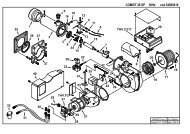
GENERAL FEATURES<br />
C.I.B. UNIGAS - M039119CE<br />
This series <strong>burners</strong> are characterised by high performaces and width in the performance curves, when the pressure in the combustion<br />
chamber is high. They are also provided with other important functional features: there are plugs which can be easily connected to the<br />
boiler and to the detecting probes, a pressure plug in the combustion chamber, all mechanical components are mounted on a plate<br />
which can be quickly taken off for maintenance. The head is adjustable by means of a graduated screw. The gas train can be mounted<br />
either on the right side or on the left side.<br />
15<br />
14<br />
13<br />
12<br />
PART I: INSTALLATION<br />
Fig. 1<br />
1 Control panel with startup switch<br />
2 Combustion head (inside)<br />
3 <strong>Gas</strong> valves group<br />
4 <strong>Gas</strong> proving system<br />
5 Cover<br />
6 Adjusting cam (double-stage, progressive and fully-modulating <strong>burners</strong>)<br />
7 Actuator (double-stage, progressive and fully-modulating <strong>burners</strong>)<br />
8 Control box<br />
9 Air pressure switch<br />
10 Fan motor<br />
11 Burner plate<br />
12 Air intake<br />
13 Printed board circuit (PCB)<br />
14 Flange<br />
15 Blast tube<br />
11<br />
1 2<br />
3<br />
The gas coming from the supply line, passes through the valves group provided with filter and stabiliser. This one forces the pressure in<br />
the utilisation limits. In the double-stage , progressive and fully- modulating <strong>burners</strong>, the electric actuator (7), that moves proportionally<br />
the air damper and the gas butterfly valve, uses an adjusting cam with variable shape. This one allows the optimisation of the gas flue<br />
values, as to get an efficient combustion. The combustion head (2) positioning determines the burner output. Fuel and comburent are<br />
routed into separated ways as far as the zone of flame generation (combustion chamber). The air (comburent) and fuel (gas, gas oil,<br />
heavy oil) are forced into the combustion chamber.<br />
The control panel, placed on the burner’s front side, shows each operating stage.<br />
5<br />
10<br />
9<br />
6<br />
7<br />
8<br />
4<br />
5
How to interpret the burner “Performance curve”<br />
C.I.B. UNIGAS - M039119CE<br />
To check if the burner is suitable for the boiler to which it must be installled, the following parameters are needed:<br />
furnace input, in kW or kcal/h (kW = kcal/h / 860);<br />
backpressure (data are available on the boiler ID plate or in the user’s manual).<br />
Example:<br />
Furnace input: 600kW<br />
Backpressure: 4mbar<br />
In the “Performance curve” diagram (Fig. 2), draw a vertical line matching the furnace input value and an horizontal line matching the<br />
backpressure value. The burner is suitable if the intersection point A is inside the performance curve.<br />
Fig. 2<br />
Data are referred to standard conditions: atmospheric pressure at 1013mbar, ambient temperature at 15°C.<br />
Checking the proper gas train size<br />
Contropressione in camera di<br />
combustione mbar<br />
Campo di lavoro bruciatori<br />
Tipo P60 Mod. M-xx.x.IT.A.0.50 - M-.xx.x.IT.A.0.65<br />
8<br />
7<br />
6<br />
5<br />
4<br />
3<br />
2<br />
1<br />
0<br />
-1<br />
A<br />
100 200 300 400 500 600 700 800 900<br />
Potenza kW<br />
To check the proper gas train size, it is necessary to know the available gas pressure value upstream the burner’s gas valve. Then<br />
subtract the backpressure. The result is called pgas. Draw a vertical line matching the furnace input value (600kW, in the example),<br />
quoted on the x-axis, as far as intercepitng the network pressure curve, according to the installed gas train (DN65, in the example).<br />
From the interception point, draw an horizontal line as far as matching, on the y-axis, the value of pressure necessary to get the requested<br />
furnace input. This value must be lower or equal to the pgas value, calculated before.<br />
Minima pressione gas in<br />
rete / Minimum inlet gas<br />
pressure (mbar)<br />
25<br />
20<br />
15<br />
10<br />
5<br />
Tipo / Type P60<br />
M-...50 (Multibloc DUNGS MB-DLE 420 B01)<br />
M-...65 (Filtro / Filter DN65+ SIEMENS VGD40.065 +SKP1x+SKP2x)<br />
0<br />
100 200 300 400 500 600 700 800 900<br />
Potenza / Output (kW)<br />
Fig. 3<br />
6<br />
Rp 2" (50)<br />
DN65
BURNERS SPECIFICATIONS<br />
Burner model identification<br />
C.I.B. UNIGAS - M039119CE<br />
Burners are identified by burner type and model. Burner model identification is described as follows.<br />
Type <strong>NG550</strong> Model M-. PR. S. .* A. 0. 50<br />
(1) (2) (3) (4) (5) (6) (7) (8)<br />
(1) BURNER TYPE<br />
NG - Natural gas burner<br />
LG - L.P.G. burner<br />
NGX - Low NOx <strong>burners</strong><br />
(2) FUEL<br />
M - Natural gas<br />
L - LPG<br />
(3) OPERATION<br />
TN - Single stage AB - Double stage<br />
PR - Progressive MD - Fully modulating<br />
(4) BLAST TUBE S - standard L - extended<br />
(5) DESTINATION COUNTRY see data plate<br />
(6) BURNER VERSION<br />
A - Standard<br />
(7) EQUIPMENT<br />
0 = 2 gas valves<br />
1= 2 <strong>Gas</strong> valves + gas proving system (option)<br />
7 = 2 gas valves + maximum gas pressure switch<br />
8= 2 <strong>Gas</strong> valves + gas proving system (option) + maximum gas pressure switch<br />
(8) GAS CONNECTION 25 = Rp1 32 = Rp1”1/4 40 = Rp1”1/2 50 = Rp2<br />
Matching the burner to the boiler<br />
The <strong>burners</strong> described in this manual have been tested with combustion chambers that comply with EN676 regulation and whose<br />
dimensions are described in the diagram . In case the burner must be coupled with boilers with a combustion chamber smaller in diameter<br />
or shorter than those described in the diagram, please contact the supplier, to verify that a correct matching is possible, with respect<br />
of the application involved. To correctly match the burner to the boiler verify the necessary input and the pressure in combustion<br />
chamber are included in the burner performance curve; otherwise the choice of the burner must be revised consulting the burner manufacturer.<br />
To choose the blast tube lenght follow the instructions of the boiler manufacturer. In absence of these consider the following:<br />
Cast-iron boilers, three pass flue boilers (with the first pass in the rear part): the blast tube must protrude no more than 100 mm into<br />
the combustion chamber.<br />
Pressurised boilers with flame reversal: in this case the blast tube must penetrate at least 50 - 100 mm into combustion chamber in<br />
respect to the tube bundle plate.<br />
The length of the blast tubes does not always allow this requirement to be met, and thus it may be necessary to use a suitably-sized<br />
spacer to move the burner backwards or to design a blast tube tha suites the utilisation (please, contact the manifacturer).<br />
Key<br />
a) Heat output in kW<br />
b) Lenght of the flame tube in meters<br />
c) Flame tube firing intensity in MW/m3 d) Combustion chamber diameter (m)<br />
Fig. 4 - Firing intensity, diameter and lenght of the test flame tube as a function of the heat<br />
input in kW.<br />
Fig. 4<br />
7
Specifications<br />
BURNERS<br />
<strong>NG550</strong><br />
M-.TN..0.25<br />
C.I.B. UNIGAS - M039119CE<br />
<strong>NG550</strong><br />
M-.TN..0.32<br />
<strong>NG550</strong><br />
M-.TN..0.40<br />
* NOTE ON THE WORKING SERVICE: the control box automatically stops after 24h of continuous working. The control box<br />
immediately starts up, automatically.<br />
8<br />
<strong>NG550</strong><br />
M-.TN..0.50<br />
Output min. - max kW 245 - 570<br />
<strong>LG550</strong><br />
L-.TN..0.25<br />
<strong>LG550</strong><br />
L-.TN..0.32<br />
Fuel Natural gas L.P.G.<br />
<strong>Gas</strong> category (see next paragraph) I 3B/P<br />
<strong>Gas</strong> rate min.- max Stm 3 /h 26 - 60 9.4 - 22<br />
<strong>Gas</strong> pressure min. - max. mbar (see Note 2)<br />
Power supply<br />
230V - 50Hz<br />
Total power consumption kW 0.92<br />
Electric motor) kW 0.62<br />
Protection<br />
Approx. weight kg 55<br />
IP40<br />
<strong>LG550</strong><br />
L-.TN..0.40<br />
<strong>LG550</strong><br />
L-.TN...0.50<br />
Valves size / <strong>Gas</strong> connection 1” / Rp 1 1” 1/4 /Rp 1 1/4 1” 1/2 /Rp 1 1/2 2”/ Rp 2 1” / Rp 1 1” 1/4 /Rp 1 1/4 1” 1/2 /Rp 1 1/2 2”/ Rp 2<br />
Operation<br />
Single stage<br />
Operating temperature °C -10 ÷ +50<br />
Storage Temperature °C -20 ÷ +60<br />
Working service*<br />
BURNERS<br />
<strong>NG550</strong><br />
M-.xx..0.25<br />
<strong>NG550</strong><br />
M-.xx...0.32<br />
<strong>NG550</strong><br />
M-.xx...0.40<br />
<strong>NG550</strong><br />
M-.xx...0.50<br />
Internittent<br />
Output min. - max kW 160 - 570<br />
<strong>LG550</strong><br />
L-.xx..0.25<br />
<strong>LG550</strong><br />
L-.xx...0.32<br />
Fuel Natural gas L.P.G.<br />
<strong>Gas</strong> category (see next paragraph) I 3B/P<br />
<strong>Gas</strong> rate min.- max Stm 3 /h 17 - 60 6.2 - 22<br />
<strong>Gas</strong> pressure min. - max. mbar (see Note 2)<br />
Power supply<br />
230V - 50Hz<br />
Total power consumption kW 0.92<br />
Electric motor kW 0.62<br />
Protection<br />
Approx. weight kg 55<br />
IP40<br />
<strong>LG550</strong><br />
L-.xx...0.40<br />
<strong>LG550</strong><br />
L-.xx...0.50<br />
Valves size / <strong>Gas</strong> connection 1” / Rp 1 1” 1/4 /Rp 1 1/4 1” 1/2 / Rp 1 1/2 2” / Rp 2 1” / Rp 1 1” 1/4 / Rp 1 1/4 1” 1/2 / Rp 1 1/2 2” / Rp 2<br />
Operation<br />
Double stage - Progressive - Fully-modulating<br />
Operating temperature °C -10 ÷ +50<br />
Storage Temperature °C -20 ÷ +60<br />
Working service*<br />
Internittent<br />
Note1: All gas flow rates are referred to Stm 3 /h (1013 mbar absolute pressure, 15 °C temperature) and are valid for G20 gas<br />
(nett calorific value H i = 34.02 MJ/Stm 3 ); for L.P.G. (nett calorific value H i = 93.5 MJ/Stm 3 )<br />
Note2: Maximum gas pressure = 360mbar (with Dungs MBDLE valves)<br />
Minimum gas pressure = see gas curves.
Low NOx <strong>burners</strong><br />
BURNERS<br />
C.I.B. UNIGAS - M039119CE<br />
* NOTE ON THE WORKING SERVICE: the control box automatically stops after 24h of continuous working. The control box<br />
immediately starts up, automatically.<br />
Country and usefulness gas categories<br />
<strong>NGX550</strong><br />
M-.xx...0.25<br />
9<br />
<strong>NGX550</strong><br />
M-.xx...0.32<br />
Output min. - max kW 132 - 490<br />
Fuel<br />
Natural gas<br />
<strong>NGX550</strong><br />
M-.xx...0.40<br />
<strong>Gas</strong> category (see next paragraph)<br />
<strong>Gas</strong> rate min.- max Stm 3 /h 14 - 52<br />
<strong>Gas</strong> pressure min. - max. mbar (see Note 2)<br />
Power supply<br />
230V - 50Hz<br />
Total power consumption kW 0.92<br />
Electric motor kW 0.62<br />
Protection<br />
Approx. weight kg 55<br />
IP40<br />
<strong>NGX550</strong><br />
M-.xx...0.50<br />
Valves size / <strong>Gas</strong> connection 1” / Rp 1 1” 1/4 / Rp 1 1/4 1” 1/2 / Rp 1 1/2 2” / Rp 2<br />
Operation<br />
Double stage - Progressive - Fully-modulating<br />
Operating temperature °C -10 ÷ +50<br />
Storage Temperature °C -20 ÷ +60<br />
Working service*<br />
Internittent<br />
Note1: All gas flow rates are referred to Stm 3 /h (1013 mbar absolute pressure, 15 °C temperature) and are valid for G20 gas<br />
(nett calorific value H i = 34.02 MJ/Stm 3 ); for L.P.G. (nett calorific value H i = 93.5 MJ/Stm 3 )<br />
Note2: Maximum gas pressure = 360mbar (with Dungs MBDLE valves)<br />
GAS<br />
CATEGORY<br />
Minimum gas pressure = see gas curves.<br />
COUNTRY<br />
I 2H AT ES GR SE FI IE HU IS NO CZ DK GB IT PT CY EE LV SI MT SK BG LT RO TR CH<br />
I 2E LU PL - - - - - - - - - - - - - - - - - - - - - - -<br />
I 2E( R ) B BE - - - - - - - - - - - - - - - - - - - - - - - -<br />
I 2L NL - - - - - - - - - - - - - - - - - - - - - - - -<br />
I 2ELL DE - - - - - - - - - - - - - - - - - - - - - - - -<br />
I 2Er FR - - - - - - - - - - - - - - - - - - - - - - - -
Performance curves<br />
BACK PRESSURE IN<br />
COMBUSTION CHAMBER mbar<br />
BACK PRESSURE IN<br />
COMBUSTION CHAMBER mbar<br />
To get the input in kcal/h, multiply value in kW by 860.<br />
C.I.B. UNIGAS - M039119CE<br />
<strong>NG550</strong> - <strong>LG550</strong> Single stage<br />
<strong>NG550</strong> - <strong>LG550</strong> Double-stage/Progressive<br />
10<br />
9<br />
8<br />
10<br />
9<br />
8<br />
7<br />
7<br />
6<br />
6<br />
5<br />
5<br />
4<br />
4<br />
3<br />
2<br />
1<br />
0<br />
3<br />
2<br />
1<br />
0<br />
-1<br />
200 250 300 350 400 450 500 550 600 650<br />
100 150 200 250 300 350 400 450 500 550 600 650<br />
kW<br />
kW<br />
<strong>NGX550</strong> Low NOx burner<br />
9<br />
8<br />
7<br />
6<br />
5<br />
4<br />
3<br />
2<br />
1<br />
0<br />
100 200 300 400 500<br />
kW<br />
Data are referred to standard conditions: atmospheric pressure at 1013mbar, ambient temperature at 15°C.<br />
NOTE: The performance curve is a diagram that represents the burner performance in the type approval phase or in the laboratory<br />
tests, but does not represent the regulation range of the machine. On this diagram the maximum output point is usually reached by adjsuting<br />
the combustion head to its “MAX” position (see paragraph “Adjusting the combustion head”); the minimum output point is reached<br />
setting the combustion head to its “MIN” position. During the first ignition, the combustion head is set in order to find a<br />
compromise between the burner output and the generator specifications, that is why the minimum output may be different from the Performance<br />
curve minimum.<br />
10
Pressure in the network/gas rate curves<br />
Natural gas <strong>burners</strong><br />
<strong>NG550</strong> Single stage<br />
GAS PRESSURE mbar<br />
L.P.G. Burners<br />
<strong>LG550</strong> L-TN..25 Single stage<br />
GAS PRESSURE mbar<br />
GAS PRESSURE mbar<br />
<strong>LG550</strong> L-PR.. Double-stage/Progressive<br />
Low NOx <strong>burners</strong><br />
<strong>NGX550</strong> Double-stage/Progressive<br />
GAS PRESSURE mbar<br />
70<br />
60<br />
50<br />
40<br />
30<br />
20<br />
10<br />
0<br />
20 30 40 50 60 70<br />
110<br />
60<br />
50<br />
40<br />
30<br />
20<br />
10<br />
90<br />
70<br />
50<br />
30<br />
C.I.B. UNIGAS - M039119CE<br />
R p 1" (25)<br />
R p 1"¼ (32)<br />
R p 1"½ (40)<br />
R p 2" (50)<br />
<strong>Gas</strong> rate Stm 3 /h<br />
10<br />
8 10 12 14 16 18 20 22 24 26<br />
100<br />
80<br />
60<br />
40<br />
20<br />
<strong>Gas</strong> rate Stm 3 /h<br />
Rp 1" (25)<br />
Rp 1" (25)<br />
0<br />
6 8 10 12 14 16 18 20 22 24<br />
<strong>Gas</strong> rate Stm 3 /h<br />
Rp 1" (25)<br />
Rp 1"¼ (32)<br />
Rp 1"½ (40)<br />
Rp 2" (50)<br />
0<br />
10 20 30 40 50 60<br />
<strong>Gas</strong> rate Stm 3 /h<br />
11<br />
<strong>NG550</strong> Double-stage/Progressive<br />
70<br />
60<br />
50<br />
40<br />
30<br />
20<br />
10<br />
0<br />
15 25 35 45 55 65 75<br />
<strong>LG550</strong> L-TN..32/40/50 Single stage<br />
30<br />
26<br />
22<br />
18<br />
14<br />
10<br />
6<br />
<strong>LG550</strong> L-PR.. Double-stage/Progressive<br />
Rp 1"<br />
Rp 1"¼<br />
Rp 1"½ (40)<br />
Rp 2" (50)<br />
<strong>Gas</strong> rate Stm 3 /h<br />
Rp 1"¼ (32) Rp 1"½ (40)<br />
Rp 2" (50)<br />
2<br />
8 10 12 14 16 18 20 22 24 26<br />
30<br />
25<br />
20<br />
15<br />
10<br />
5<br />
Rp 1"¼ (32)<br />
Rp 2" (50)<br />
<strong>Gas</strong> rate Stm 3 /h<br />
Rp 1"½ (40)<br />
0<br />
5 10 15 20 25 30<br />
<strong>Gas</strong> rate Stm 3 /h
12<br />
Overall dimensions (mm)<br />
Standard <strong>burners</strong><br />
* S = measure referred to <strong>burners</strong> fitted with standard blast tube<br />
L = measure referred to <strong>burners</strong> fitted with extended blast tube<br />
Recommended boiler drilling jig and burner flange<br />
DN A(S*) A(L*) B(S*) B(L*) C<br />
D<br />
±5mm<br />
E<br />
±5mm<br />
F G H J K L M N Omin Omax P Q R S T W X Y<br />
NG/<strong>LG550</strong> 25/32 843 943 253 353 590 671 245 426 165 178 384 241 384 M10 247 157 192 174 552 377 175 69 543 533 155<br />
NG/<strong>LG550</strong> 40 843 943 253 353 590 744 318 426 165 178 384 241 384 M10 247 157 192 174 552 377 175 69 553 533 155<br />
NG/<strong>LG550</strong> 50 843 943 253 353 590 744 318 426 165 178 384 241 384 M10 247 157 192 174 552 377 175 69 603 533 155<br />
C.I.B. UNIGAS - M039119CE
13<br />
Low NOx BurnerLow NOx <strong>burners</strong><br />
* S = measure referred to <strong>burners</strong> fitted with standard blast tube<br />
L = measure referred to <strong>burners</strong> fitted with extended blast tube<br />
Recommended boiler drilling jig and burner flangeRecommended boiler<br />
drilling jig and burner flange<br />
DN A(S*) A(L*) B(S*) B(L*) C<br />
D<br />
±5mm<br />
E<br />
±5mm<br />
F G H J K L M N Omin Omax P Q R S T W X Y<br />
<strong>NGX550</strong> 25/32 874 974 253 353 590 671 245 426 176 198 384 241 384 M10 247 157 192 174 552 377 175 69 543 533 168<br />
<strong>NGX550</strong> 40 874 974 253 353 590 744 318 426 176 198 384 241 384 M10 247 157 192 174 552 377 175 69 553 533 168<br />
<strong>NGX550</strong> 50 874 974 253 353 590 744 318 426 176 198 384 241 384 M10 247 157 192 174 552 377 175 69 603 533 168<br />
C.I.B. UNIGAS - M039119CE
C.I.B. UNIGAS - M039119CE<br />
MOUNTINGS AND CONNECTIONS<br />
Packing<br />
urners are despatched in cardboard packages whose dimensions are: 1030mm x 530mm x 570mm (L x P x H)<br />
Packing cases of this type are affected by humidity; the maximum number of cases to be stacked is showed outside the packing.<br />
The following are placed in each packing case.<br />
1 Burner with gas train;<br />
1 gasket to be inserted between the burner and the boiler;<br />
1 envelope containing this manual<br />
When disposing of the burner packing and if the packing is scrapped follow the procedures laid down in the current legislation regarding<br />
the disposal of materials.<br />
Fitting the burner to the boiler<br />
To install the burner into the boiler, proceed as follows:<br />
1 make a hole on the closing door of the combustion chamber as described on paragraph “Overall dimensions”)<br />
2 place the burner to the boiler: lift it up and handle it according to the procedure described on paragraph “Handling the burner”;<br />
3 place the 4 stud bolts (5) on boiler’s door, according to the burner’s drilling template described on paragraph “Overall dimensions”;<br />
4 fasten the 4 stud bolts;<br />
5 place the gasket on the burner flange;<br />
6 install the burner into the boiler;<br />
7 fix the burner to the stud bolts, by means of the fixing nuts, according to the next picture.<br />
8 After fitting the burner to the boiler, ensure that the gap between the blast tube and the refractory lining is sealed with appropriate<br />
insulating material (ceramic fibre cord or refractory cement).<br />
The burner is designed to work positioned according to the picture below. For different installations, please contact the Technical<br />
Department.<br />
SIDE UP<br />
SIDE<br />
DOWN<br />
Keys<br />
1 Burner<br />
2 Fixing nut<br />
3 Washer<br />
4 Sealing gasket<br />
5 Stud bolt<br />
7 Blast tube<br />
14
C.I.B. UNIGAS - M039119CE<br />
GAS TRAIN CONNECTIONS<br />
This paragraph shows the gas train components which are included in the delivery and those which must be fitted by the customer. The<br />
diagram complies with regulations in force<br />
ATTENTION: BEFORE EXECUTING THE CONNECTIONS TO THE GAS PIPE NETWORK, BE SURE THAT THE<br />
MANUAL CUTOFF VALVES ARE CLOSED. READ CAREFULLY THE “WARNINGS” CHAPTER AT THE BEGINNING<br />
OF THIS MANUAL.<br />
<strong>Gas</strong> train with valves group MB-DLE (2 valves + gas filter + pressure governor) + VPS504 gas proving system<br />
1<br />
Key<br />
1 Burner<br />
2 Butterfly valve<br />
3 <strong>Gas</strong> proving system (option)<br />
4 Low gas pressure switch<br />
5 High gas pressure switch (option)<br />
7 Bellow joint<br />
8 Manual cutoff valve<br />
9 MB-DLE valve group<br />
*Note: the high gas pressure switch can be mounted either upstream the gas valve or downstream the gas valves but upstream the butterfly<br />
gas valve.<br />
To mount the gas train, proceed as follows:<br />
1) in case of threaded joints: use proper seals according to the gas used;<br />
2) fasten all the items by means of screws, according to the next diagrams, observing the mounting direction for each item.<br />
NOTE: the bellow joint, the manual valve and the gaskets are not part of the standard supply.<br />
The procedures of installation fo the gas valves are showed in the next paragraph.<br />
2<br />
ATTENTION: once the gas train is mounted according to the diagram, the gas proving test mus be performed, according to<br />
the procedure set by the laws in force.<br />
ATTENTION: it is recommended to mount filter and gas valves to avoid that extraneous material drops inside the valves,<br />
during maintenance and cleaning operation of the filters (both the filters outside the valves group and the ones built-in the<br />
gas valves).<br />
MULTIBLOC DUNGS MB-DLE 405..412<br />
Mounting<br />
1. Mount flange onto tube lines: use appropriate sealing agent (see Fig. 7);<br />
2. insert MB-DLE: note position of O rings (see Fig. 7);<br />
3. tighten screws A, B, C and D (Fig. 5 - Fig. 6), accordind to the mounting positions (Fig. 8);<br />
4. after installation, perform leakage and functional test;<br />
5. disassembly in reverse order.<br />
4<br />
MANUFACTURER INSTALLER<br />
9<br />
3<br />
15<br />
4 5<br />
7 8
A B<br />
MULTIBLOC DUNGS MB-DLE 415..420<br />
Mounting<br />
1. Loosen screws A and B do not unscrew (Fig. 5 - Fig. 6).<br />
2. unscrew screws C and D (Fig. 5 - Fig. 6).<br />
3. Remove MultiBloc between the threaded flanges (Fig. 6).<br />
4. After mounting, perform leakage and functional tests.<br />
C<br />
D<br />
Once the train is installed, connect the gas valves group plug.<br />
<strong>Gas</strong> Proving System VPS504 (Option)<br />
C.I.B. UNIGAS - M039119CE<br />
Fig. 5 Fig. 6 Fig. 7 Fig. 8<br />
A<br />
B<br />
A<br />
C<br />
B D<br />
Fig. 9 Fig. 10 Fig. 11 Fig. 12<br />
ATTENTION: once the gas train is mounted according to the diagram, the gas proving test mus be performed, according to<br />
the procedure set by the laws in force.<br />
The VPS504 check the operation of the seal of the gas shut off valves. This check, carried out as soon as the boiler thermostat gives a<br />
start signal to the burner, creates, by means of the diaphragm pump inside it, a pressure in the test space of 20 mbar higher than the<br />
supply pressure.<br />
To install the DUNGS VPS504 gas proving system on the MD-DLE valves group, proceed as follows:<br />
1 turn off gas supply.;<br />
2 Switch off power supply.<br />
3 remove the Multibloc’s screw plugs (Fig. 13-A);<br />
4 iInsert sealing rings (10,5 x 2,25) into VPS 504 (Fig. 14-B, Fig. 13-B)<br />
5 Torque screws 3, 4, 5, 6 (M4 x16) Fig. 13-C<br />
Only use screws with metric thread on reassembly (modification, repair).<br />
6 On completion of work, perform a leak and functional test.<br />
C<br />
D<br />
16<br />
MOUNTING POSITIONS<br />
MOUNTING POSITIONS
B<br />
A<br />
C.I.B. UNIGAS - M039119CE<br />
Fig. 13 Fig. 14<br />
When wishing to monitor the test, install a pressure gauge ranged to that of the pressure supply point PA (Fig. 14). If the test cycle is<br />
satisfactory, after a few seconds the consent light LC (yellow) comes on. In the opposite case the lockout light LB (red) comes on. To<br />
restart it is necessary to reset the appliance by pressing the illuminated pushbutton LB.<br />
17<br />
LC<br />
PA<br />
LB<br />
C
ELECTRICAL CONNECTIONS<br />
To execute the electrical connections, proceed as follows:<br />
1 find the plug or the plugs, according to the model:<br />
7 poles plug for the power supply (for all models);<br />
4 poles plug (progressive <strong>burners</strong>);<br />
3-poles plug;<br />
C.I.B. UNIGAS - M039119CE<br />
Respect the basic safety rules. make sure of the connection to the earthing system. do not reverse the phase and<br />
neutral connections. fit a differential thermal magnet switch adequate for connection to the mains.<br />
ATTENTION: before executing the electrical connections, pay attention to turn the plant’s switch to OFF and be<br />
sure that the burner’s main switch is in 0 position (OFF) too. Read carefully the chapter “WARNINGS”, and the<br />
“Electrical connections” section.<br />
WARNING: the burner is fitted with a bridge between terminals T6 and T8 on CN2-TAB connector (external side link,<br />
male connector); remove this bridge before thermostat connection.<br />
WARNING: if the cable that connects the thermostats and the control box should be longer than 3 meters, insert a<br />
sectioning relay following the attached electrical wiring diagram..<br />
2 execute the electrical connections to the plugs, according to the burner model (see next paragraph);<br />
3 once all the connections are accomplished, check the fan motor direction (sse next paragraphs);<br />
4 now the burner is ready to start up.<br />
Identification of linking connectors<br />
Burner supply connector<br />
(Fig. 18, Fig. 20)<br />
Probe connection connector<br />
(fully modulating <strong>burners</strong>, Fig. 22)<br />
HIGH/LOW flame connector<br />
(progressive <strong>burners</strong> , Fig. 20<br />
Fan motor connector<br />
(Fig. 19 - Fig. 21)<br />
18<br />
Fig. 15<br />
Fig. 16<br />
Fig. 17<br />
IMPORTANT: before operating the burner, be sure all connectors are linked as shown in the diagrams.
Single stage burner connectors:<br />
Progressive burner connectors<br />
C.I.B. UNIGAS - M039119CE<br />
Fig. 18 - 7-poles connector Fig. 19 - Electric motor 3-pole connector<br />
Fig. 20 - 7-poles and 4-poles connectors Fig. 21 - Electric motor 3-poles connector<br />
Key<br />
C1 LOW FLAME TIME METER<br />
C2 HIGH FLAME TIME METER<br />
FU1 FAN MOTOR LINE FUSE<br />
FU3 LINE FUSE<br />
IL BURNER LINE SWITCH<br />
IM FAN MOTOR LINE SWITCH<br />
KM1 FAN MOTOR CONTACTOR<br />
LAF BURNER IN HIGH FLAME INDICATOR LIGHT<br />
LB INDICATOR LIGHT FOR BURNER LOCK-OUT<br />
LBF BURNER IN LOW FLAME SIGNALLING LAMP<br />
MV FAN MOTOR<br />
ST THERMOSTATS O PRESSURE SWITCHES SERIE<br />
TAB HIGH LOW FLAME THERMOSTAT/PRESSURE SWITCH<br />
TS SAFETY THERMOSTAT/PRESSURE SWITCH<br />
CONN-MOTORE FAN MOTOR CONNECTOR<br />
CONN-LINEA BURNER POWER SUPPLY CONNNECTOR<br />
CONN-TAB HIGH-LOW FLAME CONNECTOR<br />
($) IF "TAB" USED REMOVE THE BRIDGE BETWEEN TERMINALS T6-<br />
T8<br />
19
Fig. 22 - Probes connection<br />
Power supply without neutral<br />
C.I.B. UNIGAS - M039119CE<br />
If the power supply to the burner is 230V phase-phase (without the neutral wire), with the Siemens LME.. control box (see Appendix),<br />
between the terminal 2 on the board and the earth terminal, an RC Siemens RC466890660 filter must be inserted.<br />
Key<br />
C - Capacitor (22nF/250V)<br />
R - Resistor (1Mohm)<br />
(***) RC466890660 - RC Siemens filter<br />
(Code: 2531003)<br />
Key<br />
C1 LOW FLAME TIME METER<br />
FU1 LINE FUSE FOR FAN MOTOR<br />
FU3 LINE FUSE<br />
FU4 AUXILIARY FUSE<br />
IL BURNER LINE SWITCH<br />
IM FAN MOTOR LINE SWITCH<br />
KM1 FAN MOTOR REMOTE CONTACTOR<br />
SIEMENS RWF40 MODULATION REGULATOR<br />
LB BURNER LOCKOUT SIGNALLING LAMP<br />
LBF BURNER IN LOW FLAME SIGNALLING LAMP<br />
MV FAN MOTOR<br />
SD-0÷10V VOLTAGE SIGNAL<br />
SD-0/4÷20mA CURENT SIGNAL<br />
SD-PRESS PRESSURE PROBE<br />
SMA MAN/AUTO SELECTOR<br />
SMF OPERATION SELECTOR MIN-0-MAX<br />
ST PRESSURE SWITCHES OR THERMOSTATS SERIE<br />
TS SAFETY THERMOSTAT/PRESSURE SWITCH<br />
20<br />
Fig. 23<br />
R<br />
C<br />
SIEMENS
Combustion head pressure curves vs. the gas flow rate<br />
C.I.B. UNIGAS - M039119CE<br />
Curves are referred to pressure= 0mbar in the combustion head!<br />
The curves referred to the gas pressure in the combustion head, depending on the gas flow rate, are referred to the burner in the combustion<br />
stage (percentage of residual O 2 in the flues as shown in the “Recommended combustion values” table and CO in the standard<br />
limits). During this stage, the combustion head, the gas butterfly valve and the servocontrol are at the maximum opening. Refer to<br />
Fig. 24, showing the correct way to measure the gas pressure, considering the values of pressure in combustion chamber, surveyed by<br />
means of the pressure gauge or taken from the boiler’s Technical specifications.<br />
1<br />
Key<br />
1 Generator<br />
2 Pressure outlet on the combustion chamber<br />
3 <strong>Gas</strong> pressure outlet on the butterfly valve<br />
4 Differential pressure gauge<br />
2 4<br />
3<br />
Fig. 24<br />
Measuring the gas pressure in the combustion head<br />
In order to measure the pressure in the combustion head, insert the pressure gauge probes: one into the generator’s pressure outlet<br />
(Fig. 24-2) to get the pressure in the combustion chamber and the other one into the butterfly valve’s pressure outlet of the burner (Fig.<br />
24-3). On the basis of the measured differential pressure, it is possible to get the maximum flow rate: in the pressure - rate curves<br />
(showed on the next paragraph), it is easy to get the burner output in kW or Stm3/h (quoted on the x axis) from the pressure measured<br />
in the combustion head (quoted on the y axis).<br />
NOTE: THE PRESSURE-RATE CURVES ARE APPROXIMATE; FOR A PROPER SETTING OF THE GAS RATE, PLEASE REFER<br />
TO THE GAS METER READING.<br />
Plugs for pressure measurement<br />
To measure the pressure in the combustion chamber, as far as this series, a pressure plug is provided upstream the burner’s blast<br />
tube.<br />
Fan air pressure plug Pressure in combustion chamber plug<br />
21
C.I.B. UNIGAS - M039119CE<br />
<strong>Gas</strong> pressure in combustion head vs. gas flow rate curves<br />
<strong>Gas</strong> pressure in<br />
combustion head<br />
<strong>Gas</strong> pressure in<br />
combustion head<br />
<strong>NG550</strong><br />
10<br />
9<br />
8<br />
7<br />
6<br />
5<br />
4<br />
3<br />
2<br />
1<br />
0<br />
15 20 25 30 35 40 45 50 55 60 65<br />
<strong>LG550</strong> L.P.G.<br />
25<br />
20<br />
15<br />
10<br />
<strong>Gas</strong> rate Stm 3 /h<br />
5<br />
5 7 9 11 13 15 17 19 21 23 25<br />
L.P.G. rate Stm 3 /h<br />
To perform the adjustments, unscrew the fixing screws and remove the burner cover.<br />
22<br />
<strong>NGX550</strong><br />
12<br />
11<br />
10<br />
9<br />
8<br />
7<br />
6<br />
5<br />
4<br />
3<br />
2<br />
1<br />
0<br />
10 15 20 25 30 35 40 45 50 55<br />
ATTENTION: before starting the burner up, be sure that the manual cutoff valves are open and check that the pressure<br />
upstream the gas train complies the value quoted on paragraph “Technical specifications”. Be sure that the<br />
mains switch is closed.<br />
ATTENTION: During commissioning operations, do not let the burner operate with insufficient air flow (danger of<br />
formation of carbon monoxide); if this should happen, make the gas decrease slowly until the normal combustion<br />
values are achieved.<br />
WARNING: NEVER LOOSE THE SEALED SCREWS! OTHERWISE, THE DEVICE WARRANTY WILL BE INVALIDATE!<br />
4<br />
3<br />
5<br />
1<br />
2<br />
Keys<br />
1 Valve group<br />
2 Cover<br />
3 <strong>Gas</strong> proving system<br />
4 Control panel<br />
5 Blast tube
Startup Output<br />
C.I.B. UNIGAS - M039119CE<br />
The start-up heat output shall not exceed 120 kW (single stage <strong>burners</strong>) or 1/3 of nominal output (double-stage, progressive or fully<br />
modulating <strong>burners</strong>). In order to comply with these requirements, <strong>burners</strong> are provided with butterfly valve and/or slow-opening safety<br />
valve. On double-stage, progressive or modulating <strong>burners</strong>, the low flame ouptut must be higher than the minimum ouptut quoted in the<br />
performance curve (see “<strong>Gas</strong> pressure in combustion head vs. gas flow rate curves” on page 22).<br />
IMPORTANT! the combustion air excess must be adjusted according to the in the following chart.<br />
Adjustments - brief description<br />
Adjust the air and gas flow rates at the maximum output (“high flame”) first, by means of the air damper and the adjusting cam respectively.<br />
Check that the combustion parameters are in the suggested limits.<br />
Check the flow rate measuring it on the counter or, if it was not possible, verifying the combustion head pressure by means of a differential<br />
pressure gauge, as described on par. “Measuring the gas pressure in the combustion head” on page 20.<br />
Then, adjust the combustion values corresponding to the points between maximum and minimum: set the shape of the adjusting<br />
cam foil. The adjusting cam sets the air/gas ratio in those points, regulating the opening-closing of the throttle gas valve.<br />
.Set, now, the low flame output, acting on the low flame microswitch of the actuator in order to avoid the low flame output increasing<br />
too much or that the flues temperature gets too low to cause condensation in the chimney.<br />
Adjustment procedure<br />
To change the burner setting during the testing in the plant, follows the next procedure, according to the burner operation.<br />
Before starting the burner up, adjust the valves group slow opening: to set the slow opening remove cover T, reverse it upside down<br />
and use it as a tool to twist screw VR. Decrease the ignition flow rate by screwing, increase it by unscrewing. Do not use a screwdriver<br />
on the screw VR!<br />
Note: the screw VSB must be removed only in case of replacemente of the coil.<br />
1 remove the burner cover<br />
2 startup the burner by turning its main switch A to on: if the burner locks (LED B on in the control panel) press the RESET button (C)<br />
on the control panel ().<br />
3 remove the actuator cover: set it to the ignition position (ignition position= 0° on the air damper index ID - see figure on pag.23);<br />
4 (Progressive/Fully-modulating <strong>burners</strong>) Before starting the burner up, drive the high flame actuator microswitch matching the low<br />
flame one (in order to let the burner operates at the lowest output) to safely achieve the high flame stage.<br />
As for the setting, refer to this correspondence table.<br />
Berger STA<br />
I<br />
II<br />
III<br />
IV<br />
VS<br />
Recommended combustion parameters<br />
Fuel Recommended (%) CO 2 Recommended (%) O 2<br />
Natural gas 9 ÷ 10 3 ÷ 4.8<br />
LPG 11 ÷ 12 2.8 ÷ 4.3<br />
Berger STA12: On this actuator, the manual control of the air damper is not provided; the setting of the cams is carried out working<br />
with a screwdriver on the VS screw placed on the cam.<br />
Siemens SQN72: a key is provided to move cams I and IV, the other cams can be moved by means of screws. On the Siemens<br />
actuator the AUTO/MAN mode is provided (see picture).<br />
23<br />
Siemens SQN72<br />
BERGER STA Siemens SQN72<br />
High flame position (set to 90°) I I (red)<br />
Low flame and ignition position IV III (orange)<br />
Stand-by position (set to 0°) II II (blue)<br />
Not used III IV (black)<br />
IV<br />
III<br />
II<br />
I<br />
AUTO/MAN
C.I.B. UNIGAS - M039119CE<br />
5 go on adjusting air and gas flow rates: check, continuosly, the flue gas analisys, as to avoid combustion with little air; dose the air<br />
according to the gas flow rate change following the steps quoted below;<br />
6 drive the burner to high flame stage, by means of the thermostat TAB (except single-stage models).<br />
7 acting on the pressure stabiliser of the valves group, adjust the gas flow rate in the<br />
high flame stage as to meet the values requested by the boiler/utilisation:<br />
C VS T(VR)<br />
- Multibloc MB-DLE:The pressure governor is adjusted by operating the screw VS<br />
located under the cover C. By screwing down the pressure is increased and by<br />
unscrewing it is reduced. The valve is adjusted by means of the RP regulator after<br />
slackening the locking screw VB by a number of turns. By unscrewing the regulator<br />
VSB<br />
RP the valve opens, screwing the valve closes. The pressure stabilizer is adjusted by<br />
operating the screw VS located under the cover C. By screwing down the pressure is<br />
increased and by unscrewing it is reduced.<br />
RP<br />
Pressure stabiliser is factory-set. The setting values must be locally adapted<br />
to machine conditions. Important! Follow the instructions of the burner manufacturer!<br />
To adjust the air flow rate, proceed as follows, according to the burner operation (singlestage,<br />
double-stage, prograssive or fully-modulating).<br />
Adjustements for single-stage <strong>burners</strong><br />
8 loosen VR screw (see picture below)<br />
9 move the ID index towards + or -, in order to increase or decrease the air flow-rate, according to the required combustion values;<br />
10 fasten the VR screw again.<br />
VR<br />
ID<br />
Fig. 26 Fig. 27<br />
Double-stage, progressive or fully-modulating <strong>burners</strong><br />
11 still in the high flame operation and with the actuator on its 90° position, find the V screw on the adjusting cam SV (see next picture),<br />
matching with the bearings that move along the foil and related to the actuator position.<br />
12 unscrew the V srew to increase the air folw rate, unscrew to decrease it<br />
13 once the maximum flow rate is fixed, shortcircuit for a while, the thermostat TAB T6 and T7 terminals (see pag. 35), as far as the<br />
fully-modulating <strong>burners</strong>, see next paragraph. The actuator will move towards the low flame position as to meet the next screw V;<br />
then remove the bridge;<br />
14 then adjust the screw V related to that position;<br />
15 shortcircuit, again for a while, the TAB T6 and T7 terminals and repeat from point 11;<br />
16 repeat all these instructions for all the actuator stroke, in order to define the foil shape.<br />
Note: If it should be necessary to adjust the rating of the burner in low flame, work on the related actuator cam After this operation,<br />
check the gas rate and verify the combustion values. In case of lack or excess of air, work on the screws V of the adjusting cam (see<br />
pictures) matching the setting point of the air rate in low flame; unscrew to increase the air rate or screw to decrease it.<br />
Fully modulating <strong>burners</strong><br />
To adjust the air rate in low flame and in the intermediate points, proceed as follow.<br />
1 Keep pushed for 5 seconds the EXIT button on the modulator (); when the LED with the hand symbol lights up, press the arrow button,<br />
driving the actuator to the maximum opening position progressively;<br />
2 stop its stroke when it meets each screw V: adjust the air rate by adjusting the V screw that matches each bearing.<br />
3 Push the EXIT button to quit the manual mode.<br />
24<br />
SC SV<br />
VB<br />
V
Adjusting the combustion head<br />
C.I.B. UNIGAS - M039119CE<br />
The burner is factory-set with the combustion head at the position that refers to the "MAX" output. The maximum output setting refers to<br />
the “fully-ahead” position of the combustion head, as far as standard models (Fig. 29), and to “fully-backward” position for low NOx <strong>burners</strong><br />
(Fig. 30). As for “fully-ahead” position, it means that the head is towards the boiler, “fully-backward” position means that the head<br />
is towards the operator. As far as the reduced output operation, progressively move the combusiton head towards the “MIN” position,<br />
rotating clockwise the VRT screw (Fig. 28). The ID index shows how much the combustion head moved.<br />
Calibration of air and gas pressure switches<br />
The air pressure switch locks the control box if the air pressure is not the one requested. If it happens, unlock the burner by means of<br />
the control box unlock pushbutton, placed on the burner control panel. The gas pressure switches check the pressure to avoid the<br />
burner operate when the pressure value is not in the requested pressure range.<br />
Calibration of air pressure switch (only for single stage <strong>burners</strong>)<br />
Calibration is carried out as follows:<br />
Remove the transparent plastic cap.<br />
Once air and gas setting have been accomplished, startup the burner.<br />
ID<br />
VRT<br />
Fig. 29 - Head in “fully-ahead position” Fig. 30 - Head in “fully-backward position”<br />
While the burner is operating, rotate slowly and clockwise the adjusting ring nut VR, until the burner locks; read the pressure value<br />
on the scale of the pressure switch and set it again to a value reduced by the 15%.<br />
Repeat the start-up cycle and check the burner runs properly.<br />
Refit the transparent plastic cover on the pressure switch.<br />
25<br />
Fig. 28
C.I.B. UNIGAS - M039119CE<br />
Calibration of air pressure switch (double-stage, progressive and fully-modulating)<br />
To calibrate the air pressure switch, proceed as follows:<br />
Remove the transparent plastic cap.<br />
Once air and gas setting have been accomplished, startup the burner.<br />
During the pre-purge phase o the operation, turn slowly the adjusting ring nut VR in the clockwise direction until the burner lockout,<br />
then read the value on the pressure switch scale and set it to a value reduced by 15%.<br />
Repeat the ignition cycle of the burner and check it runs properly.<br />
Refit the transparent plastic cover on the pressure switch.<br />
Calibration of low gas pressure switch<br />
As for the gas pressure switch calibration, proceed as follows:<br />
Be sure that the filter is clean.<br />
Remove the transparent plastic cap.<br />
While the burner is operating at the maximum output, test the gas pressure on the pressure port of the minimum gas pressure<br />
switch.<br />
Slowly close the manual cutoff valve (placed upstream the pressure switch, see gas train installation diagram), until the detected<br />
pressure is reduced by 50%. Pay attention that the CO value in the flue gas does not increase: if the CO values are higher than the<br />
limits laid down by law, slowly open the cutoff valve as to get values lower than these limits.<br />
Check that the burner is operating correctly.<br />
Clockwise turn the pressure switch adjusting ring nut (as to increase the pressure value) until the burner stops.<br />
Slowly fully open the manual cutoff valve.<br />
Refit the transparent plastic cover on the pressure switch.<br />
Calibration is carried out as follows:<br />
Remove the transparent plastic cap.<br />
With the burner in operation at the maximum power, test the pressure on the pressure port of the pressure switch;<br />
Slowly close the manual shut-off valve upstream the pressure switch (see gas train installation diagram) until the detected pressure<br />
is reduced by 50%.<br />
Check that the burner works properly.T<br />
Then screw down the adjusting ring nut until the burner lockout.<br />
Fully open the manual shut-off valve<br />
Refit the transparent plastic cover on the pressure switch.<br />
Adjusting the high gas pressure switch (when provided)<br />
To calibrate the high pressure switch, proceed as follows according to its mounting position:<br />
1 remove the pressure switch plastic cover;<br />
2 if the maximum pressure switch is mounted upstreaam the gas valves: measure the gas pressure in the network, when flame is off;<br />
by means of the adjusting ring nut VR, set the value read, increased by the 30%.<br />
3 if the maximum pressure switch is mounted downstream the “gas governor-gas valves” group and upstream the butterfly valve:<br />
light the burner, adjust it according to the procedure in the previous paragrph. Then, measure the gas pressure at the operating<br />
flow rate, downstream the “gas governor-gas valves” group and upstream the butterfly valve; by means of the adjusting ring nut<br />
VR, set the value read on step 2, increased by the 30%;<br />
4 replace the plastic cover.<br />
Fig. 31<br />
26<br />
VR
LIMITATIONS OF USE<br />
C.I.B. UNIGAS - M039119CE<br />
THE BURNER IS AN APPLIANCE DESIGNED AND CONSTRUCTED TO OPERATE ONLY AFTER BEING CORRECTLY CON-<br />
NECTED TO A HEAT GENERATOR (E.G. BOILER, HOT AIR GENERATOR, FURNACE, ETC.), ANY OTHER USE IS TO BE CONSI-<br />
DERED IMPROPER AND THEREFORE DANGEROUS.<br />
THE USER MUST GUARANTEE THE CORRECT FITTING OF THE APPLIANCE, ENTRUSTING THE INSTALLATION OF IT TO<br />
QUALIFIED PERSONNEL AND HAVING THE FIRST COMMISSIONING OF IT CARRIED OUT BY A SERVICE CENTRE AUTHORI-<br />
SED BY THE COMPANY MANUFACTURING THE BURNER.<br />
A FUNDAMENTAL FACTOR IN THIS RESPECT IS THE ELECTRICAL CONNECTION TO THE GENERATOR’S CONTROL AND<br />
SAFETY UNITS (CONTROL THERMOSTAT, SAFETY, ETC.) WHICH GUARANTEES CORRECT AND SAFE FUNCTIONING OF<br />
THE BURNER.<br />
THEREFORE, ANY OPERATION OF THE APPLIANCE MUST BE PREVENTED WHICH DEPARTS FROM THE INSTALLATION<br />
OPERATIONS OR WHICH HAPPENS AFTER TOTAL OR PARTIAL TAMPERING WITH THESE (E.G. DISCONNECTION, EVEN<br />
PARTIAL, OF THE ELECTRICAL LEADS, OPENING THE GENERATOR DOOR, DISMANTLING OF PART OF THE BURNER).<br />
NEVER OPEN OR DISMANTLE ANY COMPONENT OF THE MACHINE.<br />
OPERATE ONLY THE MAIN SWITCH, WHICH THROUGH ITS EASY ACCESSIBILITY AND RAPIDITY OF OPERATION ALSO<br />
FUNCTIONS AS AN EMERGENCY SWITCH, AND ON THE RESET BUTTON.<br />
IN CASE OF A BURNER SHUT-DOWN, RESET THE CONTROL BOX BY MEANS OF THE RESET PUSHBUTTON. IF A SECOND<br />
SHUT-DOWN TAKES PLACE, CALL THE TECHNICAL SERVICE, WITHOUT TRYING TO RESET FURTHER.<br />
WARNING: DURING NORMAL OPERATION THE PARTS OF THE BURNER NEAREST TO THE GENERATOR (COUPLING<br />
FLANGE) CAN BECOME VERY HOT, AVOID TOUCHING THEM SO AS NOT TO GET BURNT.<br />
Burner control panel<br />
Single-stage and double-stage <strong>burners</strong><br />
F G H<br />
PART II: OPERATION<br />
B<br />
L I D<br />
Fig. 32 -<br />
27<br />
C<br />
A
C.I.B. UNIGAS - M039119CE<br />
Fig. 33 - Progressive <strong>burners</strong> only<br />
Keys<br />
A Mains switch ON - OFF<br />
B Lockout signalling lamp<br />
C Reset button for control box<br />
D <strong>Gas</strong> pressure switch consent signalling lamp<br />
F High flame operation signalling lamp (or air damper opening during pre-purge stage)<br />
G Low flame operation signalling lamp<br />
H Ignition transformer in operation signalling light<br />
I EV2 opening signalling lamp<br />
L EV1 opening signalling lamp<br />
P Modulator (on fully modulating <strong>burners</strong> only)<br />
Q Operation selector MAN - AUTO (operation in manual or automatic mode):<br />
MIN = operation with minimum output<br />
0 = Stop<br />
MAX = operation at the maximum output<br />
Q<br />
28<br />
P
OPERATION<br />
C.I.B. UNIGAS - M039119CE<br />
Set to ON position the mains switch A on the burner electrical board front panel.<br />
Check the control box (see Appendix) is not in the lockout position (LED B on), if necessary reset it by means of the pushbutton C<br />
(reset), pushing for less than 3 seconds (otherwise the control box will switch to the “Diagnostics” mode).<br />
Check that the control thermostats or pressure switches start the burner up.<br />
Check the gas supply pressure is sufficient (LED D on).<br />
Only <strong>burners</strong> provided with gas proving system: the gas proving system check cycle starts; when the check is accomplished it is<br />
signalled by the light of the LC LED on the device. When the valves check is finished, the start up cycle of the burner begins. In the<br />
case of a leak in a valve, the gas proving system locks and its red LB LED lights.<br />
To reset the device press its reset pushbutton (See “<strong>Gas</strong> Proving System VPS504 (Option)” on page 16.)<br />
All <strong>burners</strong><br />
.BEFORE STARTING UP THE BURNER, BE SURE THAT THE MAIN SWITCH IS ON AND THE MANUAL SHUTOFF<br />
VALVES ARE OPEN. READ CAREFULLY THE “WARNINGS” NOTES ON THIS MANUAL.<br />
LC<br />
LB<br />
When the startup cycle begins, the actuator drives the air damper to the maximum opening position, the fan motor starts and the<br />
pre-purge phase begins.<br />
During the pre-purge phase, the complete opening of the air damper is signalled by the LED E on the frontal panel of the electrical<br />
board.<br />
At the end of the pre-purge phase, the air damper goes to the ignition position, the ignition transformer comes on (signalled by the<br />
LED H) and few seconds later the solenoid valves EV1 and EV2 are energized (LEDs L and I on the front panel).<br />
The flame must light up in the safety time (few seconds after the gas valve opening), totherwise the gas proving system locks out.<br />
Few seconds after the opening of the valves, the ignition transformer and the lamp H turn off. The burner is now on.<br />
Some seconds after the gas valve opening, the burner starts the automatic operation: it drives to the high flame or low flame stage<br />
according to the plant request (only for progressive <strong>burners</strong> - PR) or drives to the position reqired from the modulator (only fulltmodulating<br />
<strong>burners</strong> - MD).<br />
Single stage <strong>burners</strong>: the burner is on at the maximum power; the LEDs E and G are on;<br />
High-low flame <strong>burners</strong>: the burner is on in low flame (LED G is on); some seconds later the high flame operation begins and the<br />
burner switches automatically to high flame (LED E is on) or remains in low flame operation, depending on the plant needs.<br />
Modulating <strong>burners</strong>: they are provided with the Siemens RWF40 modulator , placed on the burner side. As for the modulator operationm<br />
see the related manual.<br />
29<br />
VPS504
C.I.B. UNIGAS - M039119CE<br />
At least once a year carry out the maintenance operations listed below. In the case of seasonal servicing, it is recommended to carry<br />
out the maintenance at the end of each heating season; in the case of continuous operation the maintenance is carried out every 6<br />
months.<br />
WARNING: ALL OPERATIONS ON THE BURNER MUST BE CARRIED OUT WITH THE MAINS DISCONNECTED AND<br />
THE FUEL MANAUL CUTOFF VALVES CLOSED!<br />
ATTENTION: READ CAREFULLY THE “WARNINGS” CHAPTER AT THE BEGINNIG OF THIS MANUAL..<br />
ROUTINE OPERATIONS<br />
Clean and check the gas filter cartdrige, if necessary replace it (Fig. 34 on).<br />
Remove, check and clean the combustion head (Fig. 40 on).<br />
Check the ignition and detection electrodes, clean and adjust if necessary (see Fig. 46). In case of doubr, check the detection current<br />
according to the schemes in Fig. 47.<br />
Check and grease of sliding and rotating parts.<br />
ATTENTION! When servicing, if it was necessary to disassemble the gas train parts, remember to execute the gas proving<br />
test, once the gas train is reassembled, according to the procedure imposed by the law in force.<br />
Removing the filter in the MULTIBLOC DUNGS MB-DLE 405..412<br />
Check the filter at least once a year!<br />
Change the filter if the pressure difference between pressure connection 1 and 3 (Fig. 34-Fig. 35)is Δp > 10 mbar.<br />
Change the filter if the pressure difference between pressure connection 1 and 3 (Fig. 34-Fig. 35) is twice as high compared to the last<br />
check.<br />
You can change the filter without removing the fitting.<br />
1 Interrupt the gas supply closing the on-off valve.<br />
2 Remove screws 1 ÷ 4 using the Allen key n. 3 and remove filter cover 5 in Fig. 36.<br />
3 Remove the filter 6 and replace with a new one.<br />
4 Replace filter cover 5 and tighten screws 1 ÷ 4 without using any force and fasten.<br />
5 Perform leakage and functional test, pmax. = 360 mbar.<br />
6 Pay attention that dirt does not fall inside the valve.<br />
6<br />
➞<br />
2<br />
1<br />
0<br />
5 34 4 3 5<br />
Fig. 34<br />
Fig. 36<br />
PART III: MAINTENANCE<br />
➞<br />
6<br />
30<br />
1<br />
0<br />
1<br />
2<br />
3<br />
p e<br />
0 3 pe<br />
Fig. 35<br />
4<br />
p a<br />
4<br />
p a<br />
5<br />
p Br<br />
5<br />
p Br<br />
6
C.I.B. UNIGAS - M039119CE<br />
Removing the filter in theMULTIBLOC DUNGS MB-DLE 415 - 420 B01 1” 1/2 - 2”<br />
Check the filter at least once a year!<br />
Change the filter if the pressure difference between pressure connection 1 and 2 (Fig. 37-Fig. 38) Δp> 10 mbar.<br />
Change the filter if the pressure difference between pressure connection 1 and 2 (Fig. 37-Fig. 38) is twice as high compared to the last<br />
check.<br />
You can change the filter without removing the fitting.<br />
1 Interrupt the gas supply closing the on-off valve.<br />
2 Remove screws 1 ÷ 6 (Fig. 39).<br />
3 Change filter insert.<br />
4 Re-insert filter housing, screw in screws 1 ÷ 6 without using any force and fasten.<br />
5 Perform leakage and functional test, pmax. = 360 mbar.<br />
6 Pay attention that dirt does not fall inside the valve.<br />
1<br />
5 5<br />
4<br />
23<br />
Fig. 37<br />
Removing and cleaning the combustion head<br />
A<br />
D<br />
0<br />
B<br />
Fig. 39<br />
E<br />
32 4<br />
1 Remove the 4 screws V1, V2, V3, V4 and the couple of screws S1 and S2 (Fig. 40).<br />
C<br />
ATTENTION: the screw V1 is longer than the other and must be replaced in its seat.<br />
2 Slacken the butterfly valve adjusting rod (Fig. 41) and take it out pulling outside.<br />
3 Remove the connector CR of the ionization electrode (Fig. 42).<br />
4 Unplug cable CA of the ignition electrode EA (Fig. 42) and extract it from the flange by removing the rubber G (Fig. 42).<br />
5 To remove the head, the operator must pull it towards himself.<br />
6 Once the combustion head is removed, check that the air and gas holes are not obstructed.<br />
7 Clean the combustion head by means of a vacuum cleaner or, in case of scale, scrape it off by means of a scratchbrush.<br />
8 To reassemble the plate, follow the procedure in reversed order.<br />
CAUTION: while assembling, before tightening screws V1, V2, V3, V4, tighten screws S1 and S2, then fasten V1, V2, V3, V4.To<br />
remove the head, the operator must pull it towards himself. Once the combustione head is removed, check that the air and gas holes<br />
are not obstructed (Fig. 122 - H). Clean the combustion head by a compressed air blow or, in case of scale, scrape it off by a<br />
31<br />
1<br />
0<br />
1<br />
2<br />
3<br />
p e<br />
0 3 pe<br />
Fig. 38<br />
4<br />
p a<br />
4<br />
p a<br />
5<br />
p Br<br />
5<br />
p Br<br />
6
scratchbrush.<br />
V4<br />
V1<br />
V2<br />
Replacing the electrodes<br />
V3<br />
S1<br />
S2<br />
C.I.B. UNIGAS - M039119CE<br />
Fig. 40 Fig. 41 Fig. 42<br />
Fig. 43 Fig. 44 Fig. 45<br />
.To remove the electrodes, proceed as follows once the combustion head is removed (see “Removing and cleaning the combustion<br />
head” on page 31):<br />
1 disconnect the cables from the electrodes (ER = detection electrode; EA = ignition electrode);<br />
2 loosen the fixing screw (V);<br />
3 remove the electrodes and replace them, observing the measures quoted on next paragraph;<br />
4 re-connect the cables and re-assemble the combustion head (see next picture).<br />
ER<br />
EA<br />
32<br />
LOCKED<br />
UNLOCKED<br />
CR<br />
V<br />
H<br />
H<br />
G<br />
CR<br />
CA<br />
EA<br />
CA<br />
A<br />
B
Electrodes position setting<br />
C.I.B. UNIGAS - M039119CE<br />
ATTENTION: avoid the ignition and detection electrodes to contact metallic parts (blast tube, head, etc.), otherwise the boiler’s operation<br />
would be compromised. Check the electrodes position after any intervention on the combustion head. The gap between the ignition<br />
electrode and the ground is 4 ÷ 5 mm (see Fig. 46).<br />
Detection electrode<br />
Checking the ionisation current<br />
If the burner locks out, execute the following inpesctions. To measure the detection signals refer to the diagrams in Fig. 47 . If the signal<br />
is less than the value shown, check the position of the detection electrode, the electrical contacts and if necessary replace the detection<br />
electrode (see “Electrodes position setting” on page 33).<br />
Seasonal stop<br />
Flame<br />
To stop the burner in the seasonal stop, proceed as follows:<br />
1 turn the burner main switch to 0 (Off position)<br />
2 disconnect the power mains<br />
3 close the fuel valve of the supply line<br />
Ground electrode<br />
ignition electrode<br />
Fig. 46<br />
Fig. 47<br />
Burner disposal<br />
In case of disposal, follow the instructions according to the laws in force in your country about the “Disposal of materials”.<br />
33<br />
detection electrode<br />
<strong>NG550</strong> <strong>NGX550</strong><br />
Detection electrode<br />
µA DC SCALE<br />
Connector<br />
2<br />
Control box Minimum detection signal<br />
Siemens LME21-22 3 µA
34<br />
TROUBLESHOOTING<br />
CAUSE<br />
l = with any control box;<br />
s = with only LGB2../LMG2../LME11/LME2..<br />
(*) In such cases, insert the circuit SIEMENS “RC466890660” ()See chapter “Electrical connections”)<br />
THE BURNER<br />
DOESN’TSTART<br />
MAIN SWITCH OPEN <br />
LACK OF GAS <br />
MAXIMUM GAS PRESSURE SWITCH DEFECTIVE (IF<br />
PROVIDED) <br />
CONTINUE WITH PRE-<br />
PURGE<br />
DOESN’T START AND<br />
LOCK-OUT<br />
DOESN’T START AND<br />
REPEATS THE CYCLE<br />
STARTS AND REPEATS<br />
THE CYCLE<br />
STARTS AND LOCK-OUTВ<br />
TROUBLE<br />
THERMOSTATS/PRESSURE SWITCHES DEFECTIVE <br />
OVERLOAD TRIPPED INTERVENTION <br />
AUXILIARIES FUSE INTERRUPTED <br />
CONTROL BOX FAULTY <br />
DEFECTIVE SERVOCONTROL (IF PROVIDED) <br />
AIR PRESSURE SWITCH FAULT OR BAD SETTING <br />
MINIMUM GAS PRESSURE SWITCH DEFECTIVE OR GAS<br />
FILTER DIRTY <br />
IGNITION TRANSFORMER FAULT <br />
IGNITION ELECTRODES BAD POSITION <br />
DETECTION ELECTRODE BAD POSITION <br />
BUTTERFLY VALVE BAD SETTING <br />
DEFECTIVE GAS GOVERNOR <br />
GAS VALVE DEFECTIVE <br />
BAD CONNECTION OR DEFECTIVE HIGH/LOW FLAME<br />
THERMOSTAT OR PRESSURE SWITCH (IF PROVIDED)<br />
THE FLAME MONITOR<br />
DEVICE DOESN’T<br />
GIVECONSENT TO START<br />
DOESEN’T SWITCH TO<br />
HIGH FLAME<br />
DOESEN’T RETURN IN<br />
LOW FLAME<br />
HE SERVO CONTROL IS<br />
LOCK AND VIBRATE<br />
<br />
WRONG SETTING SERVO CONTROL CAM l l l<br />
UV PROBE DIRTY OR DEFECTIVE (IF PROVIDED) l l l<br />
PHASE-NEUTRAL INVERTED s<br />
s<br />
PHASE-PHASE SUPPLY OR PRESENCE OF VOLTAGE ON<br />
THE NEUTRAL CONDUCTOR(*)<br />
LOCK-OUT DURING<br />
OPERATION<br />
TURNS OF AND REPEATS<br />
CYCLE DURING<br />
OPERATION<br />
C.I.B. UNIGAS - M039119CE
SPARE PARTS<br />
*S:standard blast tube<br />
L: extended blast tube<br />
C.I.B. UNIGAS - M039119CE<br />
Desription Code<br />
<strong>NG550</strong> <strong>LG550</strong> <strong>NGX550</strong><br />
COVER 1011801 1011801 1011801<br />
CONTROL BOX 2020468 2020468 2020468<br />
DETECTION ELECTRODE 2080108 2080108 2080108<br />
INGNITION ELECTRODE 2080218 2080218 2080270<br />
INGNITION ELECTRODE 2080234 2080234 -<br />
GASKET 2110056 2110056 2110056<br />
FAN WHEEL 2150049 2150049 2150049<br />
GAS PRESSURE SWITCH 2160077 2160077 2160077<br />
AIR PRESSURE SWITCH 2160053 2160053 2160053<br />
IGNITION TRANSFORMER MOD. COFI 2170138 2170138 2170138<br />
IGNITION TRANSFORMER MOD. DANFOSS 2170233 2170233 2170233<br />
MOTOR 2180711 2180711 2180711<br />
VALVE GROUP Rp1 2190341 2190341 2190341<br />
VALVE GROUP Rp1 1/4 2190342 2190342 2190342<br />
VALVE GROUP Rp1 1/2 21903L3 21903L3 21903L3<br />
VALVE GROUP Rp2 21903L4 21903L4 21903L4<br />
GAS PROVING SYSTEM (option) 2191604 2191604 2191604<br />
ADJUSTING CAM FOIL 2440236 2440236 2440236<br />
ACTUATOR (double stage, progressive and fully-modulating) - Berger<br />
STA13<br />
2480074 2480074 2480074<br />
ACTUATOR (double stage, progressive and fully-modulating) - Siemens<br />
SQN72<br />
24800A4 24800A4 24800A4<br />
COMBUSTION HEAD 30600F2 30600F9 30600G0<br />
BLAST TUBE (*S) 30900F4 30900F4 30910K7<br />
BLAST TUBE (*L) 30900H9 30900H9 30910K6<br />
COMBUSTION HEAD WITH ELECTRODES (standard blast tube) 3501835 3501834 3501838<br />
COMBUSTION HEAD WITH ELECTRODES (extended blast tube) 3501835 3501834 3501839<br />
INGNITION CABLE 6050153 6050153 6050153<br />
DETECTION CABLE 6050214 6050214 6050214<br />
ELECTRONIC BOARD 6100541 6100541 6100541<br />
35
36<br />
BURNER EXPLODED VIEW<br />
POSITION DESCRIPTION POSITION DESCRIPTION<br />
1 EXTENDED BLAST TUBE 23 CONTROL BOX<br />
2 GENERATOR GASKET 24 IGNITION TRANSFORMER<br />
3 THREADED GAS PIPE 25 ACTUATOR<br />
4 FLANGE 26 AIR PRESSURE SWITCH<br />
5 FLANGE 27 OUTPUT CONTROLLER<br />
6 GAS PROVING SYSTEM 28 PRINTED CIRCUIT BOARD<br />
7 COVER FIXING SCREW 29 FRONT CONTROL PANEL<br />
8 AIR INTAKE 30 FRONT CONTROL PANEL<br />
9 AIR INTAKE 31 LIGHT<br />
10 PRESSURE PLUG 32 LIGHT<br />
11 BRACKET 33 CONTACTOR<br />
12 COVER 34 LOCK-OUT RESET BUTTON<br />
13 FAIRLEAD 35 PROTECTION<br />
14 FAIRLEAD 36 SWITCH<br />
15 FAIRLEAD 37 FUSE<br />
16 FLANGED PIPE 38 GAS MANIFOLD<br />
17 BURNER HOUSING 39 EXTENDED COMBUSTION HEAD (ASSY)<br />
18 MOTOR SUPPORT PLATE 40 IGNITION CABLE<br />
19 FAN WHEEL 41 DETECTION CABLE<br />
20 MOTOR 42 CONNECTOR<br />
21 TRANSMISSION 43 CONNECTOR<br />
22 GAS MANIFOLD 44 GAS VALVES GROUP WITH GOVERNOR<br />
C.I.B. UNIGAS - M039119CE
37<br />
C.I.B. UNIGAS - M039119CE
ELECTRICAL WIRING DIAGRAMS<br />
Wiring diagram 18-163 - Complete key<br />
C.I.B. UNIGAS - M039119CE<br />
C1 LOW FLAME TIME METER<br />
C2 HIGH FLAME TIME METER<br />
ER FLAME DETECTION ELECTRODE<br />
EV1,2 GAS ELECTRO-VALVES (OR VALVES GROUP)<br />
FU1 FAN MOTOR LINE FUSE<br />
FU2 LINE FUSE<br />
FU3 LINE FUSE<br />
FU4 AUXILIARY FUSE<br />
IL BURNER LINE SWITCH<br />
IM FAN MOTOR LINE SWITCH<br />
KM1 FAN MOTOR CONTACTOR<br />
LAF BURNER IN HIGH FLAME INDICATOR LIGHT<br />
LME2x330 CONTROL BOX<br />
LME22.330 CONTROL BOX<br />
LB INDICATOR LIGHT FOR BURNER LOCK-OUT<br />
LBF BURNER IN LOW FLAME INDICATOR LIGHT<br />
LEV1 INDICATOR LIGHT FOR OPENING OF ELECTRO-VALVE EV2<br />
LEV2 INDICATOR LIGHT FOR OPENING OF ELECTRO-VALVE EV2<br />
LF INDICATOR LIGHT BRUNER FUNCTIONING<br />
LPG INDICATOR LIGHT FOR PRESENCE OF GAS IN THE NETWORK<br />
LTA IGNITION TRANSFORMER INDICATOR LIGHT<br />
MV FAN MOTOR<br />
PA COMBUSTION AIR PRESSURE SWITCH<br />
PG MINIMUM GAS PRESSURE SWITCH<br />
PS LOCK-OUT RESET BUTTON<br />
PT100 TEMPERATURE PROBE<br />
PT1000 TEMPERATURE PROBE<br />
RC RC CIRCUIT<br />
SATRONIC DLG976 CONTROL BOX<br />
SATRONIC DMG972 CONTROL BOX<br />
SD-0÷10V VOLTAGE SIGNAL<br />
SD-0/4÷20mA CURRENT SIGNAL<br />
SD-PRESS PRESSURE PROBE<br />
SD-TEMP TEMPERATURE PROBE<br />
SIEMENS RWF40 MODULATOR<br />
SMA MANUAL/AUTOMATIC SELECTOR<br />
SMF MIN-0-MAX FUNCTIONING MANUAL SELECTOR<br />
ST SERIES OF THERMOSTATS OR PRESSURE SWITCHES<br />
STA13B0.36/83N23L AIR DAMPER SERVO CONTROL<br />
TA IGNITION TRANSFORMER<br />
TAB ($) HIGH-LOW THERMOSTAT/PRESSURE SWITCHES<br />
TC THERMOCOUPLE<br />
TS SAFETY THERMOSTAT OR PRESSURE SWITCH<br />
VPS504 GAS PROVING SYSTEM (OPTIONAL)<br />
(*) CN11 LGB21.330 - SINGLE STAGE VERSION ONLY<br />
(**) PROBE CONNECTION (SEE SHEET 4)<br />
(***) WITH ELECTRIC SUPPLY WITHOUT NEUTRAL VERSION ONLY<br />
($) IF "TAB" USED REMOVE THE BRIDGE BETWEEN TERMINALS T6-T8<br />
ACTUATOR CAMS BERGER STA13B0.36/83N23L<br />
I High flame<br />
II Stand-by<br />
IV Low flame<br />
III Not used<br />
WARNING:<br />
1 - Electrical supply 230V 50/60Hz 1N a.c.<br />
2 - Do not reverse phase with neutral<br />
3 - Ensure burner is properly earthed<br />
38
SIEMENS LME11/21/22 CONTROL BOX<br />
The series of equipment LME.. is used for the starup and supervisione of<br />
1- or 2- stage gas <strong>burners</strong>. The series LME.. is interchangeable with the<br />
series LGB.. and LMG.., all diagrams and accessories are interchangeable.<br />
Comparative table<br />
LGB <strong>Series</strong> LMG <strong>Series</strong> LME <strong>Series</strong><br />
--- LMG 25.33 LME 11.33<br />
LGB 21.33 LMG 21.33 LME 21.33<br />
LGB 22.33 LMG 22.33 LME 22.33<br />
Preconditions for burner startup<br />
Burner control must be reset<br />
All contacts in the line are closed, request for heat<br />
No undervoltage<br />
Air pressure switch LP must be in its “no-load” position<br />
Fan motor or AGK25 is closed<br />
Flame detector is darkened and there is no extraneous light<br />
Undervoltage<br />
Safety shutdown from the operating position takes place should mains<br />
voltage drop below about AC 175 V (at UN = AC 230 V)<br />
Restart is initiated when mains voltage exceeds about AC 185 V (at UN =<br />
AC 230 V).<br />
Controlled intermittent operation<br />
After no more than 24 hours of continuous operation, the burner control<br />
will initiate automatic controlled shutdown followed by a restart.<br />
Reversed polarity protection with ionization<br />
If the connections of live conductor (terminal 12) and neutral conductor<br />
(terminal 2) aremixed up, the burner control will initiate lockout at the end<br />
of the safety time “TSA”.<br />
Control sequence in the event of fault<br />
If lockout occurs, the outputs for the fuel valves, the burner motor and the<br />
ignition equipment will immediately be deactivated (< 1 second).<br />
Operational status indication<br />
In normal operation, the different operating states are showed by means<br />
of the multicolor LED, inside the lockout reset button:<br />
red LED<br />
........<br />
Y yellow LED<br />
Steady on<br />
LED<br />
green LED<br />
...<br />
Off<br />
During startup, status indication takes place according to the table:<br />
Status Color code Color<br />
Waiting time tw, other<br />
waiting states<br />
Ignition phase, ignition<br />
controlled<br />
Operation, flame ok ...................................... Green<br />
Operation, flame not<br />
ok<br />
Extraneous light on<br />
burner startup<br />
Off<br />
Flashing yellow<br />
Flashing green<br />
Green - red<br />
Undervoltage Yellow - red<br />
Fault, alarm ..................................... Red<br />
Error code output<br />
(refer to “Error code<br />
table”)<br />
.....................................<br />
<br />
<br />
<br />
<br />
<br />
Flashing red<br />
APPENDIX<br />
START-UP PROGRAM<br />
As far as the startup program, see its time diagram:<br />
A Start command (switching on)<br />
This command is triggered by control thermostat / pressure controller<br />
«R». Terminal 12 receives voltage and the programming mechanism<br />
starts running. On completion of waiting time «tw» with the LME21..., or<br />
after air damper «SA» has reached the nominal load position (on completion<br />
of «t11») with the LME22..., fan motor «M» will be started.<br />
tw Waiting time<br />
During the waiting time, air pressure monitor «LP» and flame relay «FR»<br />
are tested for correct contact positions.<br />
t11 Programmed opening time for actuator «SA»<br />
(Only with LME22...) The air damper opens until the nominal load position<br />
is reached. Only then will fan motor «M» be switched on.<br />
t10 Specified time for air pressure signal<br />
On completion of this period of time, the set air pressure must have built<br />
up, or else lockout will occur.<br />
t1 Prepurge time<br />
Purging the combustion chamber and the secondary heating surfaces:<br />
required with low-fire air volumes when using the LME21... and with nominal<br />
load air volumes when using the LME22.... The diagrams show the socalled<br />
prepurge time «t1» during which air pressure monitor «LP» must<br />
indicate that the required air pressure is available. The effective prepurge<br />
time «t1» comprises interval end «tw» through «t3».<br />
t12 Programmed closing time for actuator «SA»<br />
(Only with LME22...)During «t12», the air damper travels to the low-fire<br />
position.<br />
t3 Preignition time<br />
During «t3» and up to the end of «TSA», flame relay «FR» is forced to<br />
close. On completion of «t3», the release of fuel is triggered at terminal 4.<br />
TSA Ignition safety time<br />
On completion of «TSA», a flame signal must be present at terminal 1.<br />
That flame signal must be continuously available until shutdown occurs,<br />
or else flame relay «FR» will be deenergized, resulting in lockout.<br />
t4 Interval BV1 and BV2-LR<br />
Time between the end of TSA and the signal to the second fuel valve BV2<br />
or to the load controller LR<br />
B - B' Interval for flame establishment<br />
C Burner operation position<br />
C - D Burner operation (heat production)<br />
D Controlled by "R" shutdown<br />
The burner stops and the control device is ready for a new startup.
LME11 control sequence<br />
SB / R<br />
W / GP<br />
AL<br />
M<br />
Z<br />
BV1<br />
LP<br />
FS<br />
EK2<br />
A B B´ C D<br />
tw t10 t1 t3 t3n<br />
TSA<br />
LME22 control sequence<br />
A<br />
SB / R<br />
W / GP<br />
AL<br />
B B´ C D<br />
SA<br />
LK<br />
M<br />
Z<br />
BV1<br />
(LR) BV2<br />
LP<br />
FS<br />
EK2<br />
I<br />
t10<br />
tw t1 t3 t3n<br />
t12<br />
TSA<br />
t11<br />
t4<br />
t4<br />
7101d02/0606<br />
12<br />
10<br />
3<br />
7<br />
9<br />
4<br />
5<br />
6<br />
1<br />
8<br />
11<br />
12<br />
10<br />
3<br />
7<br />
4<br />
6<br />
1<br />
8<br />
7<br />
11<br />
LME21 control sequence<br />
SB / R<br />
W / GP<br />
AL<br />
M<br />
Z<br />
BV1<br />
(LR) BV2<br />
LP<br />
FS<br />
A B B´ C D<br />
tw t10 t1 t3 t3n t4<br />
Control sequence<br />
tw Waiting time<br />
t1 Purge time<br />
TSA Ignition safety time<br />
t3 Preignition time<br />
t3n Postignition time<br />
t4 Interval between BV1 and BV2/LR<br />
t10 Specified time for air pressure signal<br />
t11 Programmed opening time for actuator SA<br />
t12 Programmed closing time for actuator SA<br />
7101d05/0206<br />
12<br />
10<br />
3<br />
7<br />
4<br />
5<br />
6 11<br />
1
LME11 connection diagram<br />
NT<br />
12<br />
R / W<br />
GP<br />
T<br />
STB<br />
L<br />
N<br />
H<br />
Si<br />
2 10 3<br />
AL<br />
LME21 connection diagram<br />
NT<br />
12<br />
R / W<br />
GP<br />
T<br />
STB<br />
L<br />
N<br />
H<br />
Si<br />
LME22 connection diagram<br />
NT<br />
12<br />
R / W<br />
GP<br />
T<br />
STB<br />
L<br />
N<br />
H<br />
Si<br />
K1<br />
K2/1 K2/2 K3<br />
M<br />
2 10 3<br />
K1<br />
K1<br />
AL<br />
M<br />
7<br />
Z<br />
7<br />
Z<br />
C control<br />
4<br />
BV1<br />
K2/1 K2/2 K3 K4<br />
4<br />
BV1<br />
5<br />
C control<br />
K2/1 K2/2 K3 K4<br />
2 10 3<br />
AL<br />
M<br />
7<br />
Z<br />
4<br />
BV1<br />
C control<br />
5<br />
BV2<br />
5<br />
BV2<br />
9<br />
9<br />
9<br />
SA<br />
LP<br />
LP<br />
LP<br />
6<br />
6<br />
6<br />
EK<br />
RESET<br />
p a<br />
EK<br />
RESET<br />
p a<br />
EK<br />
RESET<br />
p a<br />
11<br />
EK<br />
8<br />
7101 24 /0606<br />
11<br />
11<br />
EK<br />
EK<br />
8<br />
8<br />
FSV<br />
ION<br />
FSV<br />
FSV<br />
ION<br />
ION<br />
1<br />
1<br />
1<br />
Nur LME23...<br />
12 2 1<br />
br bl sw<br />
QRC<br />
Connection diagram<br />
AL Error message (alarm)<br />
BV Fuel valve<br />
EK2 Remote lockout reset button<br />
FS Flame signal<br />
GP <strong>Gas</strong> pressure switch<br />
LP Air pressure switch<br />
LR Load controller<br />
M Fan motor<br />
R Control thermostat/pressurestat<br />
SB Safety limit thermostat<br />
W Limit thermostat /pressure switch<br />
Z Ignition transformer
CONTROL PROGRAM IN THE EVENT OF FAULT<br />
If a fault occurs, all outputs will immediately be deactivated (in less<br />
than 1s).<br />
After an interruption of power, a restart will be made with the full program<br />
sequence.<br />
If the operating voltage drops below the undervoltage thresold, a<br />
safety shutdown is performed.<br />
If the operating voltage exceeds the undervoltage thresold, a restart<br />
will be performed.<br />
In case of extraneous light during “t1”, a lockout occurs.<br />
In case of extraneous light during “tw”, there is a prevention of startup<br />
and a lockout after 30 seconds.<br />
In case of no flame at the end of TSA, there will be max. 3 repetitions<br />
of the startup cycle, followed by a lockout at the end of TSA, for mod.<br />
LME11..; directly a lockout at the end of TSA for LME21-22 models.<br />
For LME11 model: if a loss of flame occurs during operation, in case of<br />
an establishment of flame at the end of TSA, there will be max. 3 repetitions,<br />
otherwise a lockout will occur.<br />
For LME21-22 models: if a loss of flame occurs during operation, there<br />
will be a lockout.<br />
If the contact of air pressure monitor LP is in working position, a prevention<br />
of startup and lockout after 65 seconds will occur.<br />
IIf the contact of air pressure monitor LP is in normal position, a<br />
lockout occurs at the end of t10.<br />
If no air pressure signal is present after completion of t1, a lockout will<br />
occur.<br />
RESETTING THE BURNER CONTROL<br />
When lockout occurs, the burner control can immediately be reset, by<br />
pressing the lockout reset button for about 1..3 seconds. The LME.. can<br />
only be reset when all contacts in the line are closed and when there is no<br />
undervoltage.<br />
LIMITATION OF REPETITIONS (only for LME11.. model)<br />
If no flame is established at the end of TSA, or if the flame is lost during<br />
operation, a maximum of 3 repetitions per controller startup can be performed<br />
via “R”, otherwise lockout will be initiated. Counting of repetitions is<br />
restarted each time a controlled startup via “R” takes place.<br />
Condensation, formation of ice and ingress of water are not<br />
permitted!<br />
CONTROL BOX LOCKED<br />
In the event of lockout, the LME.. remains locked and the red signal lamp<br />
(LED) will light up.The burner control can immediately be reset. This state<br />
is also mantained in the case fo mains failure.<br />
DIAGNOSITICS OF THE CASUE OF FAULT<br />
Press the lockout reset button for more than 3 seconds to activate the<br />
visual diagnostics.<br />
Count the number of blinks of the red signsl lamp and check the fault<br />
condition on the “Error code table” (the device repeats the blinks for<br />
regular intervals).<br />
During diagnostics, the control outputs are deactivated:<br />
- the burner remains shut down;<br />
- external fault indication is deactivated;<br />
- fault status is showed by the red LED, inside the LME’s lockout reset<br />
buttonaccording to the “Error code table”:<br />
ERROR CODE TABLE<br />
2 blinks ** No establishment of flame at the end of TSA<br />
- Faulty or soiled fuel valves<br />
- Faulty or soiled flame detector<br />
- Inadequate adjustement of burner, no fuel<br />
- Faulty ignition equipment<br />
The air pressure switch does not switch or remains in idle position:<br />
- LP is faulty<br />
3 blinks ***<br />
- Loss of air pressure signal after t10<br />
- LPis welded in normal position.<br />
4 blinks **** - Extraneous light when burner starts up.<br />
5 blinks ***** - LP is working position.<br />
6 blinks ***** Free.<br />
7 blinks ******* Loss of flame during operation<br />
- Faulty or soiled fuel valves<br />
- Faulty or soiled flame detector<br />
- Inadequate adjustement of burner<br />
8 ÷ 9 blinks Free<br />
10 blinks ********** Faulty output contacts<br />
Attention: “lockout” remote signal (terminal no. 10) not enabled<br />
- Wiring error<br />
- Anomalous voltage on ouput terminals<br />
- Other faults<br />
14 blinks ************** (only for LME4x) - CPI contact (gas valve microswitch) not closed.<br />
TECHNICAL CHARACTERISTICS<br />
Mains voltage 120V AC +10% / -15%<br />
230V AC +10% / -15%<br />
Frequency 50 ... 60 Hz +/- 6%<br />
Power consumption 12VA<br />
External primary fuse max. 10 A (slow)<br />
input current at terminal 12 max. 5 A<br />
Detection cable length max. 3m (for electrode)<br />
Detection cable length max. 20 m (laid separately, for QRA probe)<br />
Reset cable length max. 20 m (posato separatamente)<br />
Term. 8 & 10 cable length max. 20 m<br />
Thermostat cable length<br />
and other terminals<br />
max. 3 m<br />
Safety class I<br />
Index of protection IP40 (to be ensured during mounting)<br />
Operating conditions -20... +60 °C, < 95% UR<br />
Storage conditions -20... +60 °C, < 95% UR<br />
Weight approx. 160 g
C.I.B. UNIGAS S.p.A.<br />
Via L.Galvani, 9 - 35011 Campodarsego (PD) - ITALY<br />
Tel. +39 049 9200944 - Fax +39 049 9200945/9201269<br />
web site: www.cibunigas.it - e-mail: cibunigas@cibunigas.it<br />
Note: Specifications and and data subject to change. Errors and omissions excepted.