Burner System Management
Burner System Management
Burner System Management

Create successful ePaper yourself
Turn your PDF publications into a flip-book with our unique Google optimized e-Paper software.
AZL2x - LMV2x<br />
<strong>Burner</strong> <strong>System</strong> <strong>Management</strong><br />
Service manual<br />
M12916CB Rev. 01 05/2009
INDEX<br />
WARNINGS .................................................................................................................................................................................... 3<br />
MICROPROCESSOR CONTROLLED SYSTEM ............................................................................................................................ 5<br />
User interface .................................................................................................................................................................................. 5<br />
Parameters level (heating engineer) ............................................................................................................................................... 7<br />
Setting menu ................................................................................................................................................................................... 8<br />
Block 100: General information ....................................................................................................................................................... 8<br />
Block 200: <strong>Burner</strong> control ................................................................................................................................................................ 9<br />
Block 400: Setting air/fuel ratio curves .......................................................................................................................................... 12<br />
Block 500: Air/fuel ratio control ..................................................................................................................................................... 12<br />
Block 600: Actuators ..................................................................................................................................................................... 12<br />
Block 700: Error history ................................................................................................................................................................. 13<br />
Block 900: Process data ............................................................................................................................................................... 13<br />
Actuators references ..................................................................................................................................................................... 14<br />
Gas proving system ...................................................................................................................................................................... 14<br />
Air-fuel curve points ...................................................................................................................................................................... 14<br />
COMMISSIONING THE BURNER ................................................................................................................................................ 15<br />
Warm setting ................................................................................................................................................................................. 19<br />
Cold setting ................................................................................................................................................................................... 20<br />
BURNER STARTUP WITH LMV2x ALREADY PROGRAMMED ................................................................................................. 21<br />
Reset / manual lockout ................................................................................................................................................................. 23<br />
Timeout for menu operation .......................................................................................................................................................... 23<br />
Entering the Parameter levels ....................................................................................................................................................... 23<br />
Info level ........................................................................................................................................................................................ 24<br />
Service level .................................................................................................................................................................................. 26<br />
PHASES LIST............................................................................................................................................................................... 27<br />
ERROR CODE TABLE ................................................................................................................................................................. 28<br />
Wiring diagram .............................................................................................................................................................................. 34<br />
2
WARNINGS<br />
THIS MANUAL IS SUPPLIED AS AN INTEGRAL AND ESSENTIAL PART OF THE PRODUCT AND MUST BE DELIVERED TO THE<br />
USER.<br />
INFORMATION INCLUDED IN THIS SECTION ARE DEDICATED BOTH TO THE USER AND TO PERSONNEL FOLLOWING PRO-<br />
DUCT INSTALLATION AND MAINTENANCE.<br />
THE USER WILL FIND FURTHER INFORMATION ABOUT OPERATING AND USE RESTRICTIONS, IN THE SECOND SECTION<br />
OF THIS MANUAL. WE HIGHLY RECOMMEND TO READ IT.<br />
CAREFULLY KEEP THIS MANUAL FOR FUTURE REFERENCE.<br />
1) GENERAL INTRODUCTION<br />
The equipment must be installed in compliance with the regulations<br />
in force, following the manufacturer’s instructions, by qualified personnel.<br />
Qualified personnel means those having technical knowledge in the<br />
field of components for civil or industrial heating systems, sanitary<br />
hot water generation and particularly service centres authorised by<br />
the manufacturer.<br />
Improper installation may cause injury to people and animals, or<br />
damage to property, for which the manufacturer cannot be held liable.<br />
Remove all packaging material and inspect the equipment for integrity.<br />
In case of any doubt, do not use the unit - contact the supplier.<br />
The packaging materials (wooden crate, nails, fastening devices, plastic<br />
bags, foamed polystyrene, etc), should not be left within the reach of children,<br />
as they may prove harmful.<br />
Before any cleaning or servicing operation, disconnect the unit from<br />
the mains by turning the master switch OFF, and/or through the cutout<br />
devices that are provided.<br />
Make sure that inlet or exhaust grilles are unobstructed.<br />
In case of breakdown and/or defective unit operation, disconnect the<br />
unit. Make no attempt to repair the unit or take any direct action.<br />
Contact qualified personnel only.<br />
Units shall be repaired exclusively by a servicing centre, duly authorised<br />
by the manufacturer, with original spare parts.<br />
Failure to comply with the above instructions is likely to impair the unit’s<br />
safety.<br />
To ensure equipment efficiency and proper operation, it is essential that<br />
maintenance operations are performed by qualified personnel at regular<br />
intervals, following the manufacturer’s instructions.<br />
When a decision is made to discontinue the use of the equipment,<br />
those parts likely to constitute sources of danger shall be made harmless.<br />
In case the equipment is to be sold or transferred to another user, or<br />
in case the original user should move and leave the unit behind,<br />
make sure that these instructions accompany the equipment at all<br />
times so that they can be consulted by the new owner and/or the<br />
installer.<br />
For all the units that have been modified or have options fitted then<br />
original accessory equipment only shall be used.<br />
This unit shall be employed exclusively for the use for which it is<br />
meant. Any other use shall be considered as improper and, therefore,<br />
dangerous.<br />
The manufacturer shall not be held liable, by agreement or otherwise, for<br />
damages resulting from improper installation, use and failure to comply<br />
with the instructions supplied by the manufacturer.<br />
2) SPECIAL INSTRUCTIONS FOR BURNERS<br />
The burner should be installed in a suitable room, with ventilation<br />
openings complying with the requirements of the regulations in force,<br />
and sufficient for good combustion.<br />
Only burners designed according to the regulations in force should<br />
be used.<br />
This burner should be employed exclusively for the use for which it<br />
was designed.<br />
Before connecting the burner, make sure that the unit rating is the<br />
same as delivery mains (electricity, gas oil, or other fuel).<br />
Observe caution with hot burner components. These are, usually,<br />
near to the flame and the fuel pre-heating system, they become hot<br />
during the unit operation and will remain hot for some time after the<br />
burner has stopped.<br />
When the decision is made to discontinue the use of the burner, the user<br />
3<br />
shall have qualified personnel carry out the following operations:<br />
a Remove the power supply by disconnecting the power cord from the<br />
mains.<br />
b) Disconnect the fuel supply by means of the hand-operated shut-off<br />
valve and remove the control handwheels from their spindles.<br />
Special warnings<br />
Make sure that the burner has, on installation, been firmly secured to<br />
the appliance, so that the flame is generated inside the appliance<br />
firebox.<br />
Before the burner is started and, thereafter, at least once a year,<br />
have qualified personnel perform the following operations:<br />
a set the burner fuel flow rate depending on the heat input of the<br />
appliance;<br />
b set the flow rate of the combustion-supporting air to obtain a combustion<br />
efficiency level at least equal to the lower level required by the<br />
regulations in force;<br />
c check the unit operation for proper combustion, to avoid any harmful<br />
or polluting unburnt gases in excess of the limits permitted by the<br />
regulations in force;<br />
d make sure that control and safety devices are operating properly;<br />
e make sure that exhaust ducts intended to discharge the products of<br />
combustion are operating properly;<br />
f on completion of setting and adjustment operations, make sure that<br />
all mechanical locking devices of controls have been duly tightened;<br />
g make sure that a copy of the burner use and maintenance instructions<br />
is available in the boiler room.<br />
In case of a burner shut-down, reser the control box by means of the<br />
RESET pushbutton. If a second shut-down takes place, call the<br />
Technical Service, without trying to RESET further.<br />
The unit shall be operated and serviced by qualified personnel only,<br />
in compliance with the regulations in force.<br />
3) GENERAL INSTRUCTIONS DEPENDING ON FUEL USED<br />
3a) ELECTRICAL CONNECTION<br />
For safety reasons the unit must be efficiently earthed and installed<br />
as required by current safety regulations.<br />
It is vital that all saftey requirements are met. In case of any doubt,<br />
ask for an accurate inspection of electrics by qualified personnel,<br />
since the manufacturer cannot be held liable for damages that may<br />
be caused by failure to correctly earth the equipment.<br />
Qualified personnel must inspect the system to make sure that it is<br />
adequate to take the maximum power used by the equipment shown<br />
on the equipment rating plate. In particular, make sure that the<br />
system cable cross section is adequate for the power absorbed by<br />
the unit.<br />
No adaptors, multiple outlet sockets and/or extension cables are permitted<br />
to connect the unit to the electric mains.<br />
An omnipolar switch shall be provided for connection to mains, as<br />
required by the current safety regulations.<br />
The use of any power-operated component implies observance of a<br />
few basic rules, for example:<br />
- do not touch the unit with wet or damp parts of the body and/or with<br />
bare feet;<br />
- do not pull electric cables;<br />
- do not leave the equipment exposed to weather (rain, sun, etc.)<br />
unless expressly required to do so;<br />
- do not allow children or inexperienced persons to use equipment;<br />
The unit input cable shall not be replaced by the user.<br />
In case of damage to the cable, switch off the unit and contact qualified<br />
personnel to replace.<br />
When the unit is out of use for some time the electric switch supplying all<br />
the power-driven components in the system (i.e. pumps, burner, etc.)<br />
should be switched off.
3b) FIRING WITH GAS, LIGHT OIL OR OTHER FUELS<br />
GENERAL<br />
The burner shall be installed by qualified personnel and in compliance<br />
with regulations and provisions in force; wrong installation<br />
can cause injuries to people and animals, or damage to property, for<br />
which the manufacturer cannot be held liable.<br />
Before installation, it is recommended that all the fuel supply system<br />
pipes be carefully cleaned inside, to remove foreign matter that might<br />
impair the burner operation.<br />
Before the burner is commissioned, qualified personnel should inspect<br />
the following:<br />
a the fuel supply system, for proper sealing;<br />
b the fuel flow rate, to make sure that it has been set based on the<br />
firing rate required of the burner;<br />
c the burner firing system, to make sure that it is supplied for the designed<br />
fuel type;<br />
d the fuel supply pressure, to make sure that it is included in the range<br />
shown on the rating plate;<br />
e the fuel supply system, to make sure that the system dimensions are<br />
adequate to the burner firing rate, and that the system is equipped<br />
with all the safety and control devices required by the regulations in<br />
force.<br />
When the burner is to remain idle for some time, the fuel supply tap<br />
or taps should be closed.<br />
SPECIAL INSTRUCTIONS FOR USING GAS<br />
Have qualified personnel inspect the installation to ensure that:<br />
a the gas delivery line and train are in compliance with the regulations<br />
and provisions in force;<br />
b all gas connections are tight;<br />
c the boiler room ventilation openings are such that they ensure the air<br />
supply flow required by the current regulations, and in any case are<br />
sufficient for proper combustion.<br />
Do not use gas pipes to earth electrical equipment.<br />
Never leave the burner connected when not in use. Always shut the<br />
gas valve off.<br />
In case of prolonged absence of the user, the main gas delivery<br />
valve to the burner should be shut off.<br />
Precautions if you can smell gas<br />
a do not operate electric switches, the telephone, or any other item<br />
likely to generate sparks;<br />
b immediately open doors and windows to create an air flow to purge<br />
the room;<br />
c close the gas valves;<br />
d contact qualified personnel.<br />
Do not obstruct the ventilation openings of the room where gas<br />
appliances are installed, to avoid dangerous conditions such as the<br />
development of toxic or explosive mixtures.<br />
4<br />
DIRECTIVES AND STANDARDS<br />
Gas burners<br />
European directives:<br />
- Directive 90/396/CEE - Gas Appliances;<br />
- Directive 2006/95/EC on low voltage;<br />
- Directive 2004/108/CEE on electromagnetic compatibility<br />
Harmonised standards :<br />
-UNI EN 676 (Gas <strong>Burner</strong>s;<br />
-CEI EN 60335-1(Household and similar electrical appliances - Safety.<br />
Part 1: General requirements;<br />
- EN 50165 (Electrical equipment of non-electric appliances for household<br />
and similar purposes. Safety requirements.<br />
Light oil burners<br />
European directives:<br />
- Directive 2006/95/EC on low voltage;<br />
- Directive 2004/108/CEE on electromagnetic compatibility<br />
Harmonised standards :<br />
-CEI EN 60335-1(Household and similar electrical appliances - Safety.<br />
Part 1: General requirements;<br />
- EN 50165 (Electrical equipment of non-electric appliances for household<br />
and similar purposes. Safety requirements.<br />
National standards :<br />
-UNI 7824: Monobloc nebulizer burners for liquid fuels. Characteristics<br />
and test methods<br />
Heavy oil burners<br />
European directives:<br />
- Directive 2006/95/EC on low voltage;<br />
- Directive 2004/108/CEE on electromagnetic compatibility<br />
Harmonised standards :<br />
-CEI EN 60335-1 Household and similar electrical appliances - SafetyPart<br />
1: General requirements;<br />
- EN 50165 Electrical equipment of non-electric appliances for household<br />
and similar purposes. Safety requirements.<br />
National standards :<br />
-UNI 7824: Monobloc nebulizer burners for liquid fuels. Characteristics<br />
and test methods<br />
Gas - Light oil burners<br />
European directives:<br />
- Directive 90/396/CEE Gas Appliances;<br />
- Directive 2006/95/EC on low voltage;<br />
- Directive 2004/108/CEE on electromagnetic compatibility<br />
Harmonised standards :<br />
-UNI EN 676 Gas <strong>Burner</strong>s<br />
-CEI EN 60335-1(Household and similar electrical appliances - Safety.<br />
Part 1: General requirements;<br />
- EN 50165 Electrical equipment of non-electric appliances for household<br />
and similar purposes. Safety requirements.<br />
National standards :<br />
-UNI 7824: Monobloc nebulizer burners for liquid fuels. Characteristics<br />
and test methods<br />
Gas - Heavy oil burners<br />
European directives:<br />
- Directive 90/396/CEE - Gas Appliances;<br />
- Directive 2006/95/EC on low voltage;<br />
- Directive 2004/108/CEE on electromagnetic compatibility<br />
Harmonised standards :<br />
-UNI EN 676 (Gas <strong>Burner</strong>s;<br />
-CEI EN 60335-1(Household and similar electrical appliances - Safety.<br />
Part 1: General requirements;<br />
- EN 50165 Electrical equipment of non-electric appliances for household<br />
and similar purposes. Safety requirements.<br />
National standards :<br />
-UNI 7824: Monobloc nebulizer burners for liquid fuels. Characteristics<br />
and test methods
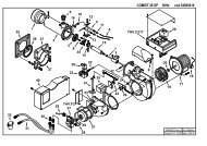
MICROPROCESSOR CONTROLLED SYSTEM<br />
The control system is made of the Siemens LMV central unit that performs all the burner control functions and of the Siemens AZL local<br />
programming unit that interfaces the system with the user.<br />
Keys<br />
1 <strong>Burner</strong><br />
2 AZL2..<br />
3 Air actuator<br />
4 Fuel actuator<br />
5 LMV2..<br />
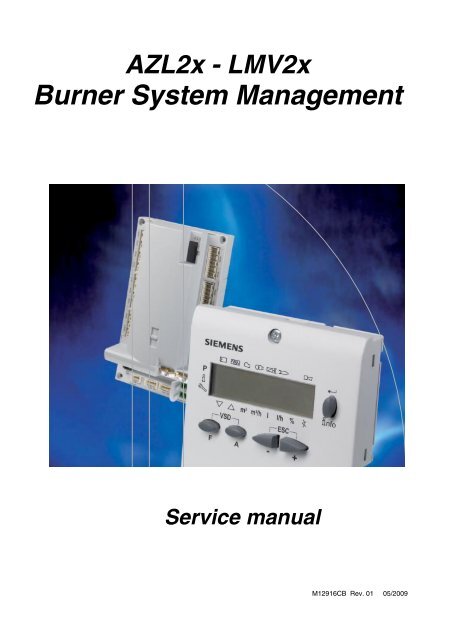
User interface<br />
The AZL2x.. display/programming unit is shown below:<br />
2<br />
d /0 0<br />
2<br />
P<br />
F<br />
3<br />
1<br />
V h min s %<br />
VSD ESC<br />
A<br />
5<br />
nfo<br />
5<br />
4
The keys functions are the following:<br />
The display will show these data:<br />
Key F<br />
Used to adjust the “fuel” actuator position (Fuel): :<br />
While pressing the F key, the “fuel” actuator position can be changed by means of the + and - keys.<br />
Key A<br />
Used to adjust the “air” actuator position (Air):<br />
While pressing the A key, the “air” actuator position can be changed by means of the + and - keys.<br />
Key F + A<br />
While pressing the two keys contemporarly, the code message will appear: by entering the proper<br />
password it is possible to access the Service mode.<br />
Info and Enter keys<br />
Used for Info and Service menues<br />
Used as Enter key in the setting modes<br />
Used as Reset key in the burner operation mode<br />
Used to enter a lower level menu<br />
-Key -<br />
Used to decrease a a value<br />
Used to enter Info and Serivce during the curve adjustments<br />
+Key +<br />
Used to increase a a value<br />
Used to enter Info and Serivce during the curve adjustments<br />
Keys (+ & - )= ESC<br />
By pressing + and - at the same time, the ESCAPE function is perfomed:<br />
to enter a lower level menu<br />
Lock+unlock codes<br />
Flame<br />
Open valves<br />
Ignition transformers energised<br />
Fan motor energised<br />
Oil pre-heater energised<br />
Plant heat request<br />
Parametere setting mode<br />
Info mode<br />
Service mode<br />
Closing actuator<br />
Opening actuator<br />
Unit measure<br />
6<br />
P<br />
V h min s %
Parameters level (heating engineer)<br />
7
Setting menu<br />
The seeting menu is divided into different blocks:<br />
<br />
Bloc. Descrizione Description Password<br />
100 Informazioni generali General OEM / Service / Info<br />
200 Controllo bruciatore <strong>Burner</strong> control OEM / Service<br />
400 Curve rapporto Ratio curves OEM / Service<br />
500 Controllo rapporto Ratio control OEM / Service<br />
600 Servocomandi Actuators OEM / Service<br />
700 Storico errori Error history OEM / Service / Info<br />
900 Dati di processo Process data OEM / Service / Info<br />
The access to the various blocks is allowed by passwords. Passwords are divided into three levels:<br />
User level (info): no password needed<br />
Service level (Service)<br />
Manifacturer level (OEM)<br />
Block 100: General information<br />
Param. Descrizione Description Password<br />
102 Data produzione (in gg-mm-aa) Identification date (yy-mm-dd) Service / Info<br />
103 Numero identificativ Identification number Service / Info<br />
104 Set di parametri preimpostati: codice cliente Preselected parameter set: customer code Service / Info<br />
105 Set di parametri preimpostati: versione Preselected parameter set: version Service / Info<br />
107 Versione softwar Software version Service / Info<br />
108 Variante software Software variant Service / Info<br />
113 Identificativo bruciatore <strong>Burner</strong> identification Service / Info<br />
121<br />
125<br />
Potenza manuale<br />
Valore non definito = modo automatico<br />
Frequenza di rete<br />
0 = 50 Hz<br />
1 = 60 Hz<br />
Manual output<br />
Undefined = automatic mode<br />
Mains frequency<br />
0 = 50 Hz<br />
1 = 60 Hz<br />
8<br />
Service / Info<br />
Service / Info<br />
126 Luminosità display Display brightness Service / Info<br />
127<br />
130<br />
Tempo disattivazione password se non viene<br />
premuto alcun tasto (valore fabbrica = 60min<br />
- range impostazione: 10 - 120 min)<br />
Azzeramento Storico errori<br />
Impostare prima il parametro a 1 e poi a 2;<br />
se compare “0” = lo Storico è stato azzerato<br />
se compare “-1” = scaduto tempo sequ. 1_2<br />
Timeout for menu operation (default value =<br />
60min - range: 10 - 120 min)<br />
Delete display of error history<br />
To delete display : set to 1 then to 2;<br />
return value “0” = error history deleted<br />
return value “-1” = timeout of 1_2 sequence<br />
OEM<br />
OEM / Service<br />
161 Numero di avarie Number of faults Service / Info<br />
162 Ore di esercizio (azzerabile da OEM) Operating hours (resettable by OEM) Service / Info<br />
163<br />
Ore di esercizio (con dispositivo sotto tensione)<br />
Operating hours (when unit is live) Service / Info<br />
164 Numero di avvii (azzerabile da OEM) Number of startups (resettable by OEM) Service / Info<br />
165 Numero totale di avvii Total number of startups Service / Info<br />
166 Volume combustibile (azzerabile da OEM) Fuel volume (resettable by OEM) Service / Info
Block 200: <strong>Burner</strong> control<br />
Param. Descrizione Description Password<br />
201<br />
208<br />
210<br />
211<br />
212<br />
213<br />
Modalità funzionamento bruciatore ( rampa<br />
combustibile, modulante / multistadio, servocomandi,<br />
ecc.)<br />
__= non definito (cancellazione curve)<br />
1 = accensione diretta a gas (G mod)<br />
2 = accensione tramite pilota gas con attacco<br />
tra le due elettrovalvole EV1/EV2 del gas<br />
(Gp1 mod)<br />
3 = accensione tramite pilota gas con attacco<br />
a monte dell’elettrovalvola EV1 del gas (Gp2<br />
mod)<br />
4 = accensione a gasolio - modulante (Lo<br />
mod)<br />
5 = accensione a gasolio - bistadio (Lo 2<br />
stage)<br />
6 = accensione a gasolio - tristadio (Lo 3<br />
stage)<br />
7 = accensione diretta a gas - regolazione<br />
pneumatica (G mod pneu)<br />
8 = accensione tramite pilota gas con attacco<br />
tra le due elettrovalvole EV1/EV2 del gas -<br />
regolazione pneumatica (Gp1 mod pneu)<br />
9 = accensione tramite pilota gas con attacco<br />
a monte dell’elettrovalvola EV1 del gas -<br />
regolazione pneumatica (Gp2 mod pneu)<br />
Stop programma<br />
0 = non attivo<br />
1 = posizione preventilazione (Ph24 - fase 24<br />
del programma)<br />
2 = posizione accensione (Ph36 - fase 36 del<br />
programma)<br />
3 = intervallo di tempo 1 (Ph44 - fase 44 del<br />
programma)<br />
4 = intervallo di tempo 2 (Ph52 - fase 52 del<br />
programma)<br />
Allarme impedimento di avviamento<br />
0 = non attivo<br />
1 = attivo<br />
Tempo aumento giri ventilatore (valore fabbrica<br />
= 2s - range impostazione: 2 - 60 s)<br />
Tempo massimo raggiungimento bassa<br />
fiamma (valore fabbrica = 45 s - range impostazione:<br />
0.2 s - 10 min)<br />
Stabilisce il massimo intervallo di tempo<br />
durante il quale il bruciatore raggiunge la<br />
minima potenza e poi si spegne<br />
Tempo minimo raggiungimento posizione di<br />
stand by (valore fabbrica = 2 s - range impostazione:<br />
2 - 60 s)<br />
<strong>Burner</strong> operating mode (fuel train, modulating<br />
/ multistage, actuators, etc..)<br />
__= undefined (delete curves)<br />
1 = gas direct ignition (G mod)<br />
2 = ignition by gas pilot connected between<br />
the two gas solenoid valves EV1/EV2 (Gp1<br />
mod)<br />
3 = ignition by gas pilot connected upstream<br />
the gas EV1 (Gp2 mod)<br />
4 = light oil ignition - modulating (Lo mod)<br />
5 = light oil ignition - double stage (Lo 2 stage)<br />
6 = light oil ignition - three stage (Lo 3 stage)<br />
7 = gas direct ignition - pneumatic regulation<br />
(G mod pneu)<br />
8 = ignition by gas pilot connected between<br />
the two gas solenoid valves EV1/EV2 - pneumatic<br />
regulation (Gp1 mod pneu)<br />
9 = ignition by gas pilot connected upstream<br />
the gas EV1 - pneumatic regulation (Gp2 mod<br />
pneu)<br />
Program stop<br />
0 = deactivated<br />
1 = pre-purge position (Ph24 - fase 24 del<br />
programma)<br />
2 = post-purge position (Ph36 - fase 36 del<br />
programma)<br />
3 = interval 1 (Ph44 - program phase 44)<br />
4 = interval 2 (Ph52 - program phase 52)<br />
Alarm in the event of start prevention<br />
0 = deactivated<br />
1 = activated<br />
Fan ramp up time (default value = 2s - range:<br />
2 - 60 s)<br />
Maximum time down to low-fire (default value<br />
= 45 s - range: 0.2 s - 10 min)<br />
It states the maximum time interval during<br />
which the burner drives to the low output and<br />
then turns off<br />
9<br />
Service / Info<br />
OEM / Service<br />
OEM / Service<br />
OEM / Service<br />
OEM / Service<br />
Min. time home run (default value = 2 s -<br />
range: 2 - 60 s) OEM / Service<br />
214 Tempo massimo inizio partenza Max. time start release Service / Info<br />
215<br />
217<br />
Limite ripetizioni catena di sicurezza (valore<br />
fabbrica = 16 - range impostazione:1 - 16)<br />
Tempo massimo per rilevazione segnale<br />
(valore fabbrica = 30s - range impostazione:<br />
5s - 10 min)<br />
Repetition limit safety loop (default value = 16<br />
- range: 1 - 16)<br />
Max. time to detector signal (default value =<br />
30s - range: 5s - 10 min)<br />
OEM / Service<br />
OEM
221<br />
222<br />
223<br />
225<br />
226<br />
227<br />
229<br />
230<br />
231<br />
232<br />
233<br />
234<br />
240<br />
241 (*)<br />
Gas: sonda rilevazione fiamma attivo (valore<br />
fabbrica = 1)<br />
0 = QRB../QRC..<br />
1 = ION / QRA..<br />
Gas: active detector flame evaluation (default<br />
value = 1)<br />
0 = QRB../QRC..<br />
1 = ION / QRA..<br />
Gas: Preventilazione (valore fabbrica = 1) Gas: Pre-purging (default value = 1)<br />
1 = attivo<br />
1 = active<br />
0 = non attivo<br />
0 = deactivated<br />
ATTENZIONE : In ambito civile la norma WARNING: in the civil field, the prepurge is<br />
EN676 rende obbligatoria la preventilazione. mandatory according to the standard EN676.<br />
In ambito industriale, vedere i casi in cui la In the industrial fiels, check if the pre purge<br />
norma EN746-2 prevede la possibilità di non can be avoided according to the stanrds<br />
fare la preventilazione.<br />
EN746-2<br />
In questi ultimi casi il bruciatore deve essere If the prepurge is not performed, the burner<br />
costruito obbligatoriamente con controllo di must be equipped with two valves and the<br />
tenuta e valvole gas in classe A.<br />
proving system.<br />
10<br />
OEM / Service<br />
OEM / Service<br />
Limite ripetizioni pressostato gas di minima Repetition limit pressure switch-min-gas<br />
pressione (valore fabbrica = 16 - range impo- (default value = 16 - range:1 - 16)<br />
stazione:1 - 16)<br />
OEM / Service<br />
Gas: tempo di preventilazione (valore fab- Gas: Prepurge time (default value = 20s -<br />
brica = 20s - range impostazione:20s - 60min) range:20s - 60min)<br />
Gas: tempo di preaccensione (valore fabbrica<br />
= 2s - range impostazione:0.2s - 60min)<br />
Gas: tempo di sicurezza 1 (TSA1) (valore<br />
fabbrica = 3s - range impostazione:0.2 - 10s)<br />
Gas: tempo di risposta a cadute di pressione<br />
entro TSA1 e TSA2 (valore fabbrica = 1.8s -<br />
range impostazione:0.2s - 9.8s)<br />
Gas: Intervallo 1 (valore fabbrica = 2s -<br />
range impostazione:0.2s - 60min)<br />
Gas: tempo di sicurezza 2 (TSA2) (valore<br />
fabbrica = 3s - range impostazione:0.2 - 10s)<br />
Gas: Intervallo 2 (valore fabbrica = 2s -<br />
range impostazione:0.2s - 60min)<br />
Gas: Tempo postcombustione (valore fabbrica<br />
= 8s - range impostazione:0.2s - 60s)<br />
Gas: Tempo postventilazione (valore fabbrica<br />
= 0.2s - range impostazione:0.2s -<br />
180min)<br />
Limite ripetizioni perdita di fiamma (valore<br />
fabbrica = 2 - range impostazione:1 - 2)<br />
Gas: esecuzione controllo tenuta (valore<br />
fabbrica = 2)<br />
0 = no controllo tenuta<br />
1 = controllo tenuta in avviamento<br />
2 = controllo tenuta in arresto<br />
3 = controllo tenuta in arresto e in avviamento<br />
Gas: Preignition time (default value = 2s -<br />
range: 0.2s - 60min)<br />
Gas: Safety time 1 (TSA1) (default value =<br />
3s - range: 0.2 - 10s)<br />
Gas: time to respond to pressure faults in<br />
TSA1 e TSA2 (default value = 1.8s - range:<br />
0.2s - 9.8s)<br />
Gas: Interval 1 (default value = 2s - range:<br />
0.2s - 60min)<br />
Gas: Safety time 2 (TSA2) (default value = 3s<br />
- range:0.2 - 10s)<br />
Gas: Interval 2 (default value = 2s -<br />
range:0.2s - 60min)<br />
Gas: postcombustion time (default value = 8s<br />
- range:0.2s - 60s)<br />
OEM / Service<br />
OEM / Service<br />
OEM<br />
OEM<br />
OEM / Service<br />
OEM<br />
OEM / Service<br />
OEM / Service<br />
Gas: Postpurge time (default value = 0.2s -<br />
range:0.2s - 180min) OEM / Service<br />
Repetition limit loss of flame (default value= 2<br />
- range:1 - 2)<br />
Gas: execution proving test (default value= 2)<br />
0 = no proving test<br />
1 = proving test on startup<br />
2 = proving test on shutdown<br />
3 = proving test on shutdown and on startup<br />
(*)<br />
It can be set only by the burner manufacturer (OEM). This parameter can be set only if the burner is equipped with a proving system..<br />
Furhter, the valve coils must not be electrically connected one to the other: they must be electrically separated. Check how coils are<br />
manufactured.<br />
242<br />
243<br />
244<br />
245<br />
Gas: tempo evacuazione controllo tenuta<br />
(valore fabbrica = 3s - range impostazione:0.2s<br />
- 10s)<br />
Gas: tempo pressione atmosferica controllo<br />
tenuta (valore fabbrica = 10s - range impostazione:0.2s<br />
- 60s)<br />
Gas: tempo riempimento controllo tenuta<br />
(valore fabbrica = 3s - range impostazione:0.2s<br />
- 10s)<br />
Gas: tempo test pressione gas (valore fabbrica<br />
= 10s - range impostazione:0.2s - 60s)<br />
OEM<br />
OEM<br />
Gas: proving test evacuation time (default<br />
value = 3s - range:0.2s - 10s) OEM<br />
Gas: proving test time atmospheric pressure<br />
(default value = 10s - range:0.2s - 60s) OEM<br />
Gas: proving test filling time (default value =<br />
3s - range:0.2s - 10s) OEM<br />
Gas: proving test time gas pressure (default<br />
value = 10s - range:0.2s - 60s)<br />
OEM
246<br />
261<br />
262<br />
265<br />
266<br />
267<br />
269<br />
270<br />
271<br />
272<br />
273<br />
274<br />
280<br />
281<br />
Gas: tempo attesa chiusura attesa consenso<br />
pressostato di minima (valore fabbrica = 10s<br />
- range impostazione:0.2s - 60s)<br />
Se la pressione del gas è troppo bassa, in<br />
fase 22 non verrà eseguito l’avviamento: il<br />
sistema compie un numero impostabile di<br />
tentativi finché non si arriva al blocco. Il<br />
tempo di attesa tra un tentativo e il successivo<br />
viene raddoppiato ad ogni tentativo.<br />
Olio: sonda rilevazione fiamma attivo (valore<br />
fabbrica = 0)<br />
0 = QRB../QRC..<br />
1 = ION / QRA..<br />
Gas: waiting time gas shortage (default value<br />
= 10s - range:0.2s - 60s)<br />
If the gas pressure is too low, in phase 22 the<br />
startup will not be performed: the system tries<br />
for a certain number of times the it locks out.<br />
The time interval between two attempts is<br />
doubled at each attempt.<br />
Oil: active detector flame evaluation (default<br />
value = 0)<br />
0 = QRB../QRC..<br />
1 = ION / QRA..<br />
Oil: prepurging (default value = 1)<br />
Olio: preventilazione (valore fabbrica = 1)<br />
0 = deactivated<br />
1 = attivo<br />
1 = activated<br />
0 = non attivo<br />
0 = deactivated<br />
In ambito civile la norma EN267 rende obbligatoria<br />
la preventilazione. In ambito indu-<br />
WARNING: in the civil field, the prepurge is<br />
striale, vedere i casi in cui la norma EN746-2<br />
mandatory according to the standard EN267.<br />
prevede la possibilità di non fare la preventila-<br />
In the industrial fiels, check if the pre purge<br />
zione.<br />
can be avoided according to the standard<br />
EN746-2<br />
Olio: tempo preventilazione (valore fabbrica<br />
= 15s - range impostazione:15s - 60min)<br />
Olio: tempo preaccensione (valore fabbrica =<br />
2s - range impostazione:0.2s - 60min)<br />
Olio: tempo di sicurezza 1 (TSA1) (valore<br />
fabbrica = 5s - range impostazione:0.2 - 15s)<br />
Olio: tempo di risposta a cadute di pressione<br />
entro TSA1 e TSA2 (valore fabbrica = 1.8s -<br />
range impostazione:0.2s - 14.8s)<br />
Olio: Intervallo 1 (valore fabbrica = 2s -<br />
range impostazione:0.2s - 60min)<br />
Olio: tempo di sicurezza 2 (TSA2) (valore<br />
fabbrica = 3s - range impostazione:0.2 - 10s)<br />
Olio: Intervallo 2 (valore fabbrica = 2s -<br />
range impostazione:0.2s - 60min)<br />
Olio: Tempo postcombustione (valore fabbrica<br />
= 8s - range impostazione:0.2s - 60s)<br />
Olio: Tempo postventilazione (valore fabbrica<br />
= 0.2s - range impostazione:0.2s -<br />
180min)<br />
Limite ripetizioni perdita di fiamma (valore<br />
fabbrica = 2 - range impostazione:1 - 2)<br />
Oil: prepurging time (default value = 15s -<br />
range:15s - 60min)<br />
Oil: preignition time (default value = 2s -<br />
range:0.2s - 60min)<br />
Oil: safety time 1 (TSA1) (default value = 5s<br />
- range:0.2 - 15s)<br />
Oil: time to respond to pressure faults in<br />
TSA1 and TSA2 (default value = 1.8s -<br />
range:0.2s - 14.8s)<br />
Oil: Interval 1 (default value = 2s -<br />
range:0.2s - 60min)<br />
Oil: safety time 2 (TSA2) (default value = 3s<br />
- range:0.2 - 10s)<br />
Oil: Interval 2 (default value = 2s -<br />
range:0.2s - 60min)<br />
Oil: Postcombustion time (default value = 8s<br />
- range:0.2s - 60s)<br />
11<br />
OEM<br />
OEM / Service<br />
OEM / Service<br />
OEM / Service<br />
OEM / Service<br />
OEM<br />
OEM<br />
OEM / Service<br />
OEM<br />
OEM / Service<br />
OEM / Service<br />
Oil: Postpurging time (default value = 0.2s -<br />
range:0.2s - 180min) OEM / Service<br />
Repetition limit value loss of flame (default<br />
value = 2 - range:1 - 2)<br />
Olio: tempo iniezione olio (valore fabbr. = 1) Oil: time oil ignition (default value = 1)<br />
0 = preaccensione corta (Ph38 - fase pro- 0 = short preignition (Ph38-progr. phase 38)<br />
gramma 38)<br />
1 = preaccensione lunga (con ventilatore) 1 = long preignition (with fan) (Ph22 - program<br />
(Ph22 - fase programma 22)<br />
phase 22)<br />
OEM<br />
OEM / Service
Block 400: Setting air/fuel ratio curves<br />
Param. Descrizione Description Password<br />
401<br />
402<br />
Curve controllo servocomando combustibile<br />
(F): si accede alla lista dei punti da impostare<br />
(da P0 a P9) - consultare paragrafo “Impostazione<br />
curve”<br />
Curve controllo servocomando aria (A): si<br />
accede alla lista dei punti da impostare (da P0<br />
a P9) - consultare paragrafo “Impostazione<br />
curve”<br />
Block 500: Air/fuel ratio control<br />
Block 600: Actuators<br />
Ratio control curve fuel actuator (F): it accesses<br />
to the parameter list of the points to be set<br />
(P0 to P9) - see paragrapf “Setting the curves”<br />
Ratio control curve air actuator (A): it accesses<br />
to the parameter list of the points to be set<br />
(P0 to P9) - see paragraph “Setting the curves”<br />
12<br />
OEM / Service<br />
OEM / Service<br />
Param. Descrizione Description Password<br />
501<br />
502<br />
545<br />
546<br />
Posizione servocomando combustibile in<br />
assenza di fiamma (no-flame)<br />
Indice 0 = posizione di sosta<br />
Indice 1 = posizione preventilazione<br />
Indice 2 = posizione postventilazione<br />
Posizione servocomando aria in assenza di<br />
fiamma (no-flame)<br />
Indice 0 = posizione di sosta<br />
Indice 1 = posizione preventilazione<br />
Indice 2 = posizione postventilazione<br />
Percentuale minima di carico per modulazione<br />
(valore fabbrica = n.d. - range impostazione:20%-100%)<br />
Percentuale massima di carico per modulazione<br />
(valore fabbrica = n.d. - range impostazione:20%-100%)<br />
No-flame position fuel actuator<br />
Index 0 = no-load position<br />
Index 1 = prepurge position<br />
Index 2 = postpurge position<br />
No-flame position air actuator<br />
Index 0 = no-load position<br />
Index 1 = prepurge position<br />
Index 2 = postpurge position<br />
Lower load limit (default value = n.d. -<br />
range:20%-100%)<br />
Higher load limite (default value = n.d. -<br />
range:20%-100%)<br />
OEM / Service<br />
OEM / Service<br />
OEM / Service<br />
OEM / Service<br />
Param. Descrizione Description Password<br />
601<br />
602<br />
606<br />
645<br />
Impostazione punto di riferimento<br />
Indice 0 = combustibile<br />
Indice 1 = aria<br />
0 = chiuso (90°)<br />
Selection of reference point<br />
Index 0 = fuel<br />
Index 1 = air<br />
0 = closed (90°)<br />
Direzione rotazione del servocomando Actuator’s direction of rotation<br />
Indice 0 = combustibile<br />
Index 0 = fuel<br />
Indice 1 = aria<br />
Index 1 = air<br />
0 = antiorario<br />
0 = counterclockwise<br />
1 = orario<br />
1 = clockwise<br />
VEDI MESSAGGIO DI “ATTENZIONE” SEE “WARNING” MESSAGE QUOTED<br />
RIPORTATO SOTTO.<br />
BELOW.<br />
Limite tolleranza per monitoraggio posizione<br />
(0.1°)<br />
Indice 0 = combustibile<br />
Indice 1 = aria<br />
Configurazione uscita analogica (valore fabbrica<br />
= 0)<br />
0 = DC 0..10 V<br />
1 = DC 2..10 V<br />
2 = DC 0/2..10 V<br />
Tolerance limit of position monitoring (0.1°)<br />
Index 0 = fuel<br />
Index 1 = air<br />
Configuration of analog output (default value<br />
= 0)<br />
0 = DC 0..10 V<br />
1 = DC 2..10 V<br />
2 = DC 0/2..10 V<br />
OEM<br />
OEM<br />
OEM / Service<br />
OEM / Service
ATTENTION: as for SQM3x actuators, set the direction according to the acutator function. As far as SQN1x actuators, set<br />
always the counterclockwise direction, independently from the model chosen for the specific function.<br />
Block 700: Error history<br />
Param. Descrizione Description Password<br />
701 Storico errori: 701 - 725.01.codice Error history: 701 - 725.01.code Service / Info<br />
° Storico errori: 701 - 725.02.codice diagnostico Error history: 701 - 725.02.diagnostic code Service / Info<br />
° Storico errori: 701 - 725.03.classe errore Error history: 701 - 725.03.error class Service / Info<br />
° Storico errori: 701 - 725.04.fase Error history: 701 - 725.04.phase Service / Info<br />
° Storico errori: 701 - 725.05.contatore avvii Error history: 701 - 725.05.startup counter Service / Info<br />
725 Storico errori: 701 - 725.06.carico Error history: 701 - 725.06.load Service / Info<br />
Block 900: Process data<br />
Param. Descrizione Description Password<br />
903<br />
922<br />
Potenza attuale (valore fabbrica = 0% - range<br />
impostazione = 0-100%)<br />
Indice 0 = combustibile<br />
Indice 1 = aria<br />
Posizione incrementale servocomandi (valore<br />
fabbrica = 0% - range impostazione = -50% -<br />
150%)<br />
Indice 0 = combustibile<br />
Indice 1 = aria<br />
Current output (default value = 0% - range =<br />
0-100%)<br />
Index 0 = fuel<br />
Index 1 = air<br />
Incremental position of actuators (default<br />
value = 0% - range = -50% - 150%)<br />
Index 0 = fuel<br />
Index 1 = air<br />
13<br />
Service / Info<br />
Service / Info<br />
942 Sorgente potenza attiva Active load source OEM / Service<br />
947 Risultato interrogazione contatti (codifica bit) Result of contact sensing (bit-coded) Service / Info<br />
950 Stato relè (codifica bit) Required relay state (bit-coded) Service / Info<br />
954<br />
Intensità di fiamma ( 0% ÷ 100%);<br />
minima corrente 30% = 4µA;<br />
massima corrente100% = 16µA;<br />
massima corrente ammissibile = 40µA.<br />
Intensity of flame (range = 0% - 100%)<br />
minimum current 30% = 4µA;<br />
maximum current100% = 16µA;<br />
maximum current possible = 40µA.<br />
Service / Info<br />
961 Stato moduli esterni e display Status of external modules and display Service / Info<br />
981 Errore memoria: codice Error memory: code Service / Info<br />
982 Errore memoria: codice diagnostica Error memory: diagnostic code Service / Info<br />
992 Flag di errore Error Flags OEM / Service
Actuators references<br />
An incremental transducer is used to ensure position feedback. Referencing of the actuators must be performed after power-on. In<br />
addition, at the end of each shutdown in phase 10, the actuators are referenced to ensure that individual stepping errors, which could<br />
lead to shutdown, do not accumulate. If a position error occurs, the system switches to the safety phase (phase 01), enabling the actuators<br />
with detected position errors to be referenced. During the following phase 10, the only actuators that are referenced are those that<br />
were not referenced before in the safety phase (phase 01). The position of the reference point can be selected depending on the type<br />
of burner design, either the CLOSED position (90°).<br />
Param. Descrizione Description Password<br />
601<br />
Impostazione punto di riferimento<br />
Indice 0 = combustibile<br />
Indice 1 = aria<br />
0 = chiuso (90°)<br />
If the acutators position is exchanged (error code: 85), the burner will lockout and will try to adjust for three times, then it will lock out.<br />
Gas proving system<br />
Valve proving is only active when firing on gas. This is a leakage test designed to detect leaking gas valves and, if necessary, to prevent<br />
the valves from opening or ignition from being switched on. Lockout is initiated. When performing valve proving, the gas valve on<br />
the burner side is opened first to bring the test space to atmospheric pressure. Then, the valve is closed whereupon the pressure in the<br />
test space must not exceed a certain level, measured by the gas leakage pressure switch (PGCP). Then, the gas valve on the mains<br />
side is opened to fill the gas pipe. When the valve is closed again, the gas pressure must not drop below a certain level. Valve proving<br />
can be parameterized to take place on startup, shutdown, or on both phases.<br />
Air-fuel curve points<br />
There are 10 air-fuel curve points: T<br />
Selection of reference point<br />
Index 0 = fuel<br />
Index 1 = air<br />
0 = closed (90°)<br />
P0 = ignition position. Only for ignition; after the ignition, the burner works between Point P1 (low flame) and point P9 (high flame)<br />
without going back to P0.<br />
P0 can be set everywhere irrespective of all the other points.<br />
14<br />
OEM
COMMISSIONING THE BURNER<br />
The LMV2x complete programming must be performed on units that has never been set before or reset units (e.g. spare parts).<br />
The programming procedure is performed by setting the following main parameters:<br />
1 type of fuel train (parameter “201”)<br />
2 air/fuel ratio curvepoints (Block “400”)<br />
3 maximum load percentage (parameter “546”)<br />
4 minimum load percentage (parameter “545”)<br />
CAUTION: if an error message as “Loc..” appears when the unit is turned to on for the first time, press ENTER (InFo) until<br />
the “Reset” message apperas. After few seconds, the message “OffUpr” will be displayed.<br />
This message shows that the unit has not been programmed before or that the operating mode (fuel train) is not set yet or that the unit<br />
has not been completely programmed. Pree keys F (Fuel) and A (Air) at the same time unitl the display shows code and next it<br />
will show 7 bars the first on the left is flashing. If the display shows “Off”, it means that the unitis already set, then see the instructions on<br />
chapter “Adjsuting the burner with LMV2x already programmed”).<br />
At the first LMV startup, the AZL display will show<br />
It means that the unit was never set or that no mode was chisen or that some parameters have to be set furthert.<br />
Push F (fuel) and A (Air) together untilthe display shows code and then a 7 digit dashed line blinking on the left.<br />
Press the “+” key until the first character of the password (the default password is 9876), then press ENTER (InFo), the character now<br />
turn to a bar while the second bar starts flashing. Press “+” until the second character is entered, then press ENTER (InFo).<br />
Repeat the procedure until the last character si set, then press ENTER (InFo), then ENTER again until the message PArA appears:<br />
then the first parameters block (“400”) will be shown:<br />
Press ENTER (InFo) again, to gain access to programming the operating mode (fuel train):<br />
In the example, set configuration 1 = direct gas ignition (G mod).<br />
Other possibilities are below listed:<br />
15
the types of fuel trains are the following:<br />
Param. Descrizione Description Password<br />
201<br />
Modalità funzionamento bruciatore ( rampa <strong>Burner</strong> operating mode (fuel train, mod / multi-<br />
comb., mod. / multistadio, servocom., ecc.) stage, actuators, etc.)<br />
__= non definito (cancellazione curve)___= __= undefined (delete curves)<br />
1 = accensione diretta a gas (G mod)<br />
1 = gas direct ignition(G mod)<br />
2 = accensione tramite pilota gas con attacco tra 2 = gas pilot ignition with connection between the<br />
le due elettrovalvole EV1/EV2 gas (Gp1 mod) two gas solenodi valves EV1/EV2 (Gp1 mod)<br />
3 = accens. tramite pilota gas con attacco a 3 = gas pilot ignition with connection upstrem the<br />
monte dell’elettrov. EV1 del gas (Gp2 mod) gas solenoid valve EV1 (Gp2 mod)<br />
4 = accensione a gasolio - modul. (Lo mod) 4 = Light Oil - modulating (Lo mod)<br />
5 = accens. a gasolio - bistadio (Lo 2 stage) 5 = Light Oil - 2stages (Lo 2 stage)<br />
6 = accens. a gasolio - tristadio (Lo 3 stage) 6 = Light Oil - 3stages (Lo 3 stage)<br />
G mod<br />
Gp1 mod<br />
Gp2 mod<br />
Lo mod<br />
Lo 2-stage<br />
16<br />
Service / Info
Lo 3-stage<br />
In the example the Gmod gas train has been set (Configuration “1”).<br />
Choose the fuel train by pressing ENTER, then press “+” / “-”. Press ENTER to confirm: number “1” will appear on the right side of the<br />
display.<br />
Then press ESC to quit. The following display is:<br />
Press “+” to show the first point to be set P0.<br />
Press F and “+” to increase the opening angle of the fuel actuator “0F” until the requested value is reached (for example 8°, see<br />
below) for the ignition point; or press F and “-” to decrease the angle:<br />
To set the air damper opening angle “0A” in the ignition point (5° for example - see below), press “A” and “+” “A” and “-” at the same<br />
time:<br />
Now the air and fuel quantities are set at the ignition point P0:<br />
By pressing “+”, point P9 can be programmed to set the air and fuel values at the maximum output<br />
go on as described above to the the opening angles of the air actuator (A) and fuel actuator (F):<br />
17
CAUTION: at the first burner adjustment, it is recommended to set the maximum output P9 at the same value (or little<br />
higher) of the ignition point, in order to safely reach point P9 next (see next paragraph).<br />
By pressing “+” the display will show:<br />
The burner is ready to startup. Now it is possible to re-set the curve points while the burner is operating (“warm setting”) by pressing<br />
the ENTER (InFo) or while the burner is in stand-by mode (“cold setting”) by pressing ESC .<br />
18
Warm setting<br />
1 Once pressed ENTER (InFo), the unit performs the prepurge cycle and stops at the ignition point P0 without ignition anyway.<br />
2 By pressing “+”, the burners lights abd the air/fuel ratio can be properly set in presence of flame.<br />
3 By pressing “+” again, the next point P1 is shown (eqaul to P0 as the unit automatically set P0=P1);<br />
4 By pressing “+” again, the “Calc” message will be displayed: the unit is processing the sir/fuel ratio curvepoints until point P9, previuosly<br />
set. Once the processing is perfomed the calculated point P2 is shown.By pressing “+” again, the “Calc” message will be<br />
displayed: the unit is processing the sir/fuel ratio curvepoints until point P9, previuosly set. Once the processing is perfomed the<br />
calculated point P2 is shown.<br />
5 By pressing “+”, it is possible to go through the processed curve until point P9 is reached.<br />
Note: if the point doesn’t blink, servomotors are still running.<br />
6 n order to set P9 with the gas flow rate according to the generator needs, follow this procedure:<br />
Note: the purpose is to fully open the gas throttle and later on to adjust the gas flow rate through the gas pressure governor.<br />
Operate smoothly opening by just a few degrees the air damper and later on increasing the gas throttle opening it by a few<br />
degrees. Keep monitoring the flue through the flue analyser. Keep the air excess inside normal figures (from 3% to 7% residual O2)<br />
operating by means for the air damper servomotor;<br />
Keep increasing the air damper opening and then the gas throttle, as done in the sequence above, remebering to get the full firing<br />
rate wih the gas throttle fully open (or the oil pressure regulator at its maximum pressure position).<br />
See example below:<br />
If, while opening the gas throttle, the gas flow rate was too high, reduce it only through the gas governor and keep opening the<br />
throttle until the 90° position is got.<br />
If the gas train is equipped with a governor and a valve with an adjustable gas flow rate, fully open also this last valve, smoothly!<br />
The gas flow rate is always set by means of the governor.<br />
7 As soon as all the devices are fully open, set the gas flow rate through the governor.<br />
8 Set the air damper position in order to get the reccomended air excess (3÷4.8% O2 on gas and 2.9÷4.9 % on oil).<br />
Note1: on high flame, if the gas flow rate is changed by means of the governor, all the other points below high flame must be checked<br />
again.<br />
9 After having set the high flame point P9, keep “-” pressed for some seconds unitl “Calc” is displayed in order to have the LMV recalculating<br />
all the points:<br />
10 the unit will automatically reach point P8 processed: check the combustion values in this point and, if necessary, change it.<br />
19<br />
Fuel<br />
Air
11 Press “-” to go down to the lower points and check the combustion values, change the points if necessary.<br />
Note: if in an intermediate point (for example P5), the change of the actuators position is important according to the processed point<br />
P5, keep pressing “-” unitl “Calc” is displayed. The curve will be processed again downwards point P1.<br />
12 press “-” to go through the lower points and check the combustion values, if necessary change the points as described above.<br />
13 By pressing ESC, at the end of the points adjusments, the parameter “546” (setting the maximum load) will be displayed; press<br />
ENTER (InFo), then “+” until 100%, then press ENTER (InFo) again, ESC and then “+”.<br />
14 The parameter “545” (setting the minimum load) is displayed: press ENTER (InFo), then “+” until 20%. Press ENTER, then press<br />
ESC for three times. The message “oP” will be displayed as well as the load percentage at the burner is working on.<br />
he hyphen related to the symbol “P” (highlited in the picture) will be off to show that the unit exited the programmig mode. The burner<br />
will then work automatically, following the curve set.<br />
.Note1: if the curvepoints settings is quit before end (by pressing ESC or for a faulty shutdown), the message “OFFUPr” (Start prevention)<br />
will be diplayed until all the curvepoints will be set.<br />
Note2: if the gas flow rate at high flame point (maximum load) is changed by means of the pressure stabiliser, all the curvepoints must<br />
be checked by going through the curve downwards and resetting them if necessary.<br />
Note3: if the point does not flash, it means thet the actuators have not reached the set position yet.<br />
Note4: if an error occurs causing a safety shutdwon during the processing of the curve, the processing itself will be interrupted.<br />
Cold setting<br />
deviation between two<br />
following points: 25°max.<br />
Angolo<br />
The ”cold setting“ (without flame) can be performed only when all the curve points values are known (for instance, in case of replacement).<br />
20<br />
Fuel
BURNER STARTUP WITH LMV2x ALREADY PROGRAMMED<br />
Once the LMV turns on, the AZL display will show<br />
The burners is basically factory set. The air/fuel ratio curve is set with the maximum output point P9 a little higher or equal to P0. To<br />
adjust the burner on the plant site, adjust the maximum output point to the flow rate values really requested. Then go through the curvepoints,<br />
by pressing “+” several times to reach point P9: then adjust the air actuator position (for the air damper) and the fuel acttuator<br />
(for the butterfly valve, in case of gas or the oil pressure governor incase of oil), by adjusting the fuel flow rate by means of the gas pressure<br />
stabiliser (for gas) or the oil pressure governor (for oil), checking the combustion valeus contemporarly. Once the burner is adjusted<br />
at the maximum output, press “-” for more than 5 seconds to process the curve downwards. The curve is then a straight line: go on<br />
checking the combustion values point by point; change them if necessary and in case linearise the curve again.<br />
Before starting the burner up, press F and A at the same time<br />
enter the password following the procedure on chapter “Programming LMV2x”.<br />
Press ENTER until the display will show:<br />
Press ENTER again: it will show<br />
press ENTER (InFo) : the display will show phase 12.<br />
Ph12: Standby phase (stationary)<br />
Ph12: Standby phase (stationary)<br />
By closing the thermostatic series, the burner startup cycle will take place:<br />
Ph22: Fan ramp up phase (fan motor = ON, safety shutoff valve = ON)<br />
Ph24: Traveling to prepurge position phase<br />
Ph30: Prepurge phase<br />
Ph36: Traveling to ignition position phase<br />
Ph38: Preignition phase<br />
Ph40: 1st safety time phase (ignition transformer ON)<br />
Ph42: 1st safety time phase (ignition transformer OFF), preignition time OFF<br />
Ph44: Interval1<br />
The startup sequence stops at phase 44.<br />
The burners is lit and is in“P1” position (low flame point):<br />
21
Set the air/fuel ratio curvepoints as described on chapter “Programming the LMV2x”<br />
Note: the other phases are<br />
Ph60 = operation (OP= in modulation)<br />
Ph62 = travelling to shutdown<br />
Ph70 = off but in prepurge after the burntime<br />
Ph72 = travelling to postpurging<br />
Ph74 = postpurge (countdown is displayed)<br />
Press ESC the parameter “546” (Setting the maximum load) is displayed<br />
Then press to exit the programming mode.<br />
The display will show:<br />
Press for a second time: the display will show the load percentage the burner is working at.<br />
When the generator reaches the programmed set-point, the burner will be in stand-by: the display will show<br />
22
Reset / manual lockout<br />
The system can be manually locked by simultaneously pressing the ENTER (InFo) button and any other button on the AZL2.... This<br />
function allows the user to stop the system from the operating level should an emergency occur. When making a reset, the following<br />
actions are carried out:<br />
Alarm relay and the fault display are off<br />
the lockout position is cancelled<br />
the unit performs a reset, then it switches to stand-by<br />
If the unit is in the lockout position, a reset can be made by pressing the InFo button for 1…3 seconds. The function is available only<br />
when the unit is in the lockout position. Longer or shorter pushes on the button do not produce a reset so that the system maintains the<br />
lockout position.<br />
Codice errore / Error code Codice diagnostico / Diagnostic code Descrizione / Meaning<br />
167 2 Blocco manuale tramite AZL2.. / Manual lockout via AZL2…<br />
Timeout for menu operation<br />
The time for automatically leaving the parameter setting level can be adjusted between 10 and 120 minutes, using the parameter 127<br />
(Timeout for menu operation). If, during that period of time, there is no operation via the AZL2..., the parameter setting level is quit and<br />
the password level reset to Info / Service.<br />
Caution! In addition, this timeout or interruption of communication between the LMV2.. and the AZL2... during the time the<br />
curves are set leads to lockout!<br />
Codice errore Error code Codice diagnostico Diagnostic code DescrizioneMeaning<br />
167 8 Blocco manualeManual locking<br />
Entering the Parameter levels<br />
By means of a proper use of the keys, it is possible to enter the various level parameters, as shown in the following flow chart:<br />
The burner and consequently the LMV2x.. are factory set; the air and fuel curves as set as well.<br />
23
Info level<br />
To enter the Info level, proceed as follows:<br />
1 in any menu position, press keys + and - at the same time, then the program will start again: the display will show OFF.<br />
2 until the display will show InFo, Press the enter (InFo) key<br />
3 then il will show the first code (167) flashing, on the right side it will show the data entered. By pressing + or - it is possible to scroll<br />
(up or down) the parameter list.<br />
4 If a dot-line is shown on the right, there is no enough room for complete visualisation: press enter again the data will be completely<br />
shown for 1 to 3 seconds. By pressing enter or + and- at the same time, the system will exit the parameter visualisation and go<br />
back to the flashing number.<br />
The Info level shows some basic parameters as:<br />
Parameter Description<br />
167 Cubic meters of fule (resettable)<br />
162 Operating hours (resettable)<br />
163 Device operating hours<br />
164 <strong>Burner</strong>s start-ups (resettable)<br />
166 Total number of start-ups<br />
113 <strong>Burner</strong> number (i.e. serial number)<br />
107 Software version<br />
102 Software date<br />
103 Device serial number<br />
104 Customer code<br />
105 Version<br />
143 Free<br />
5 Example: choose parameter 102 to show the date<br />
the display shows parameter 102 flashing on the left and characters ._._ on the right.<br />
6 press InFo for 1-3 seconds: the date will appear<br />
7 press InFo to go back to parameter “102”<br />
8 by pressing + / -, it is possible to scroll up/down the parameter list (see table above), or, by pressing ESC or InFo for more seconds,<br />
the display will show<br />
9 Once the last parameter is accessed (143) by pressing + , the End message will flash.<br />
24
10 Press InFo for more than three seconds or for more than three seconds orto return to the normal display.<br />
If a message like the one below is shown during operation,<br />
it means that the burner is locked out and the Errore code is shown (in the example “error code:4”); this message is alternating with<br />
another message<br />
Diagnostic code (in the example “diagnostic code:3”). Record the codes and find out the fault in the Error table????<br />
To perform the reset, press InFo for one second:<br />
The unit displays an event which does not lead to shutdown.<br />
The display shows current error code c: alternating with diagnostic code d:<br />
.<br />
Press InFo to return to the display of phases.<br />
Example: Error code 111 / diagnostic code 0<br />
To reset, press InFo for a second. Record the codes and check the Error List to find the type of faults.<br />
25
Service level<br />
To enter the Service mode, press InFo until the display will show:<br />
The service level shows all the information about flame intensity, actuators position, number and lock codes:<br />
Parameter Description<br />
954 Flame intensity<br />
121 % output, if set = automatic operation<br />
922 Actuators position, 00=combustibile; 01= aria<br />
161 Lock-outs number<br />
701..725 Lock-outs History (see chapter 23 in the LMV2x manual)<br />
1 the first parameter will be “954”: the percentage of flame is shown on the right. By pressinf + or - it is possible to scroll up/down the<br />
parameter list.<br />
2 Once the last parameter is accessed (143) by pressing + , the End message will blink.<br />
3 Press InFo for more than three seconds or for more than three seconds orto return to the normal display.<br />
26
PHASES LIST<br />
Fase / Phase Funzione Function<br />
Ph00 Fase blocco Lockout phase<br />
Ph01 Fase di sicurezza Safety phase<br />
Ph10 t10 = tempo raggiungimento posizione riposo t10 = home run<br />
Ph12 Pausa Standby (stationary)<br />
Ph22<br />
t22 = tempo di salita ventilatore (motore ventilatore<br />
= ON, valvola intercettazione di sicurezza = ON)<br />
27<br />
t22 = fan ramp up time (fan motor = ON, safety<br />
shutoff valve = ON)<br />
Ph24 Verso posizione preventilazione Traveling to the prepurge position<br />
Ph30 t1 = tempo preventilazione t1 = prepurge time<br />
Ph36 Verso posizione accensione Traveling to the ignition position<br />
Ph38 t3 = tempo preaccensione t3 = preignition time<br />
Ph40<br />
Ph42<br />
TSA1 = primo tempo sicurezza (trasformatore<br />
accensione ON)<br />
TSA1 = primo tempo sicurezza (trasformatore<br />
accensione OFF)<br />
TSA1= 1st safety time (ignition transformer ON)<br />
Ph44 t44 = intervallo 1 t44 = interval 1<br />
Ph50 TSA2 = secondo tempo sicurezza TSA2 = 2nd safety time<br />
Ph52 t52 = intervallo2 t52 = interval 2<br />
Ph60 Funzionamento 1 (stazionario) Operation 1 (stationary)<br />
Ph62<br />
t62 = massimo tempo bassa fiamma (funzionamento<br />
2, in preparazione per spegnimento, verso bassa<br />
fiamma)<br />
TSA1 = 1st safety time (ignition transformer OFF),<br />
t42 = preignition time OFF<br />
t62 = max. time low-fire (operation 2, preparing for<br />
shutdown, traveling to low-fire)<br />
Ph70 t13 = tempo postcombustione t13 = afterburn time<br />
Ph72 Verso posizione postcombustione Traveling to the postpurge position<br />
Ph74 t8 = tempo postventilazione t8 = postpurge time<br />
Ph80 t80 = tempo evacuazione controllo tenuta valvole t80 = valve proving test evacuation time<br />
Ph81<br />
t80 = tempo perdita pressione atmosferica, prova<br />
atmosferica<br />
t81 = leakage time test time atmospheric pressure,<br />
atmospheric test<br />
Ph82 t82 = test perdita, test riempimento t82 = leakage test filling test, filling<br />
Ph83 t80 = tempo perdita pressione gas, test pressione t83 = leakage test time gas pressure, pressure test<br />
Ph90 Tempo attesa “mancanza gas” Gas shortage waiting time
28<br />
ERROR CODE TABLE<br />
Error code Diagnostic code Meaning for LMV20.100A2BC system Recommended measures<br />
2 4 No flame at the end of TSA1<br />
3 # Air pressure failure<br />
0 Air pressure switch off<br />
1 Air pressure switch on<br />
4 Air pressure on – start prevention<br />
4 # Extraneous light<br />
0 Extraneous light during startup<br />
1 Extraneous light during shutdown<br />
2 Extraneous light during startup – start prevention<br />
7 3 Loss of flame<br />
12 # Valve proving test<br />
0 V1 leaking<br />
1 V2 leaking<br />
Check to see if valve on the gas side is leaking Check to see if there is an open-circuit<br />
Check to see if valve on the burner side is leaking<br />
Check to see if pressure switch for the leakage test is closed when gas pressure is present<br />
Check wiring to see if there is a short-circuit<br />
20 0<br />
Pmin<br />
No min. gas / oil pressure<br />
22 OFF S 0 Safety loop / burner flange open<br />
50 # Internal error Make a reset; if error occurs repeatedly, replace the unit<br />
51 # Internal error Make a reset; if error occurs repeatedly, replace the unit<br />
55 # Internal error Make a reset; if error occurs repeatedly, replace the unit<br />
56 # Internal error Make a reset; if error occurs repeatedly, replace the unit<br />
57 # Internal error Make a reset; if error occurs repeatedly, replace the unit<br />
58 # Internal error Make a reset; if error occurs repeatedly, replace the unit<br />
60 0 Internal error: No valid load controller Make a reset; if error occurs repeatedly, replace the unit<br />
65 # Internal error Make a reset; if error occurs repeatedly, replace the unit<br />
66 # Internal error Make a reset; if error occurs repeatedly, replace the unit<br />
67 # Internal error Make a reset; if error occurs repeatedly, replace the unit<br />
70 # Error fuel/air control : Position calculation modulating<br />
70 # Error fuel/air control : Position calculation modulating<br />
23 Load invalid No valid load<br />
26 Curvepoints undefined Adjust the curvepoints for all actuators<br />
71 # Special position undefined<br />
0 Standby position Parameterize the standby position for all actuators used<br />
1 Postpurge position Parameterize the postpurge position for all actuators used<br />
2 Prepurge position Parameterize the prepurge position for all actuators used<br />
3 Ignition position Parameterize the ignition position for all actuators used<br />
72 # Internal error fuel / air control Make a reset; if error occurs repeatedly, replace the unit<br />
73 # Internal error fuel/air control: Position calcul. stage<br />
23 Position calculation, multistep load invalid No valid load<br />
26 Position calculation, multistep curvepoints undefined Adjust the curvepoints for all actuators<br />
C.I.B. UNIGAS - M12916CB
29<br />
Error code Diagnostic code Meaning for LMV20.100A2BC system Recommended measures<br />
75 # Internal error fuel/air ratio control: Data clocking check<br />
1 Current load different<br />
2 Target load different<br />
4 Target positions different<br />
16 Different positions reached<br />
76 # Internal error fuel / air control Make a reset; if error occurs repeatedly, replace the unit<br />
84 # Curve slope actuators<br />
Bit 1 Valency 2..3 Fuel actuator: Curve too steep in terms of ramp rate The slope of the curve may be a maximum position change of 31° between 2 curvepoints in modulating mode<br />
Bit 2 Valency 4..7 Air actuator: Curve too steep in terms of ramp rate The slope of the curve may be a maximum position change of 31° between 2 curvepoints in modulating mode<br />
85 # Referencing error ones actuators<br />
Bit 0 Valency 1 Referencing error of fuel actuator<br />
Referencing of fuel actuator not successful. Reference point could not be reached. 1. Check to see if the actuators<br />
have been mixed up 2. Check to see if the actuator is locked or overloaded<br />
Bit 1 Valency 2…3 Referencing error of air actuator<br />
Referencing of fuel actuator not successful Reference point could not be reached. 1. Check to see if the actuators<br />
have been mixed up 2. Check to see if the actuator is locked or overloaded<br />
Bit 7 Valency >=128 Referencing error due to parameter change<br />
Parameterization of an actuator (e.g. the reference position) has been changed. To trigger new referencing, this<br />
error will be set<br />
86 # Error fuel actuator<br />
0 Position error<br />
Target position could not be reached within the required tolerance band. 1. Check to see if the actuator is locked or<br />
overloaded.<br />
Bit 0 Valency 1 Open-circuit Open-circuit detected at the actuator’s terminals. 1. Check wiring.<br />
Bit 3 Valency >=8 Curve too steep in terms of ramp rate The slope of the curve may be a maximum position change of 31° between 2 curvepoints in modulating mode<br />
Bit 4 Valency >=16 Step deviation in comparison with last referencing<br />
Actuator was overloaded or mechanically twisted. 1. Check to see if the actuator is blocked somewhere along its<br />
working range. 2. Check to see if the torque is sufficient for the application.<br />
87 # Error air actuator<br />
0 Position error<br />
Target position could not be reached within the required tolerance band. 1. Check to see if the actuator is locked or<br />
overloaded.<br />
Bit 0 Valency 1 Open-circuit Open-circuit detected at the actuator’s terminals. 1. Check wiring.<br />
Bit 3 Valency >=8 Curve too steep in terms of ramp rate The slope of the curve may be a maximum position change of 31° between 2 curvepoints in modulating mode<br />
Actuator was overloaded or mechanically twisted.<br />
Bit 4 Valency >=16 Sectional deviation in comparison with last referencing 1. Check to see if the actuator is blocked somewhere along its working range.<br />
2. Check to see if the torque is sufficient for the application.<br />
90 # Internal error burner control<br />
91 # Internal error burner control<br />
93 # Error flame signal acquisition<br />
Short-circuit at QRB...<br />
3 Short-circuit of sensor<br />
1. Check wiring.<br />
2. Flame detector possibly faulty.<br />
95 # Error relay supervision<br />
3 Ignition transformer External power supply active contact: Check wiring<br />
4 Fuel valve 1 External power supply active contact: Check wiring<br />
5 Fuel valve 2 External power supply active contact: Check wiring<br />
6 Fuel valve 3 External power supply active contact: Check wiring<br />
C.I.B. UNIGAS - M12916CB
30<br />
Error code Diagnostic code Meaning for LMV20.100A2BC system Recommended measures<br />
96 # Error relay supervision<br />
3 Ignition transformer Relay contacts have welded. Test the contacts:<br />
4 Fuel valve 1<br />
1. Unit connected to power: Fan output must be dead.<br />
5 Fuel valve 2<br />
2. Disconnect power: Disconnect fan. No resistive connection between fan output and neutral conductor<br />
allowed.<br />
6 Fuel valve 3<br />
If one of the 2 tests fails, release the unit since contact have definitively welded and safety can no longer be<br />
ensured<br />
97 # Error relay supervision<br />
0<br />
Safety relay contacts have welded or external power<br />
supply fed to safety relay<br />
Test the contacts: 1. Unit connected to power: Fan output must be dead.<br />
2. Disconnect power: Disconnect fan. No resistive connection between fan output and neutral conductor<br />
allowed. If one of the 2 tests fails, release the unit since contacts have definitively welded and safety can no<br />
longer be ensured.<br />
98 # Error relay supervision<br />
1 Ignition transformer Relay does not pull in. Make a reset; if error occurs repeatedly, replace the unit<br />
3 Fuel valve 1 Relay does not pull in. Make a reset; if error occurs repeatedly, replace the unit<br />
4 Fuel valve 1 Relay does not pull in. Make a reset; if error occurs repeatedly, replace the unit<br />
5 Fuel valve 2 Relay does not pull in. Make a reset; if error occurs repeatedly, replace the unit<br />
6 Fuel valve 3 Relay does not pull in. Make a reset; if error occurs repeatedly, replace the unit<br />
99 # Internal error relay control Make a reset; if error occurs repeatedly, replace the unit<br />
100 # Internal error relay control Make a reset; if error occurs repeatedly, replace the unit<br />
105 # Internal error contact sampling<br />
1 Pressure switch min<br />
1 Pressure switch max<br />
2 Pressure switch valve proving test<br />
3 Air pressure<br />
4 Load controller open<br />
5 Load controller on/off<br />
6<br />
7<br />
Load controller closed<br />
Safety loop / <strong>Burner</strong> flange<br />
Stuck-At failure: Can be caused by capacitive loads or supply of DC voltage to the mains voltage inputs. The<br />
diag-nostic code indicates the input where the problem occurred<br />
8 Safety valve<br />
9 Ignition transformer<br />
10 Fuel valve 1<br />
11 Fuel valve 2<br />
12 Fuel valve 3<br />
13 Reset<br />
106 # Internal error contact request Make a reset; if error occurs repeatedly, replace the unit<br />
107 # Internal error contact request Make a reset; if error occurs repeatedly, replace the unit<br />
108 # Internal error contact request Make a reset; if error occurs repeatedly, replace the unit<br />
C.I.B. UNIGAS - M12916CB
31<br />
Error code Diagnostic code Meaning for LMV20.100A2BC system Recommended measures<br />
110 # Internal error voltage monitor test Make a reset; if error occurs repeatedly, replace the unit<br />
111 0 Power supply undervoltage Mains voltage to low<br />
112 0 Mains voltage recovery Error code for triggering a reset on power restoration (no error)<br />
113 # Internal error mains voltage supervision Make a reset; if error occurs repeatedly, replace the unit<br />
115 # Internal error system counter<br />
116 0 Life in critical range Warning threshold has been reached. The unit should be replaced<br />
117 0<br />
Life exceeded<br />
Operation no longer allowed<br />
120 0 Interrupt limitation fuel counter input<br />
121 # Internal error EEPROM access<br />
Switch-off threshold has been reached<br />
Too many disturbance pulses at the fuel meters input<br />
Improve EMC<br />
122 # Internal error EEPROM access<br />
Make a reset, repeat last parameterization / check. Restore the parameter set, if error occurs re-peatedly,<br />
123 # Internal error EEPROM access<br />
replace the unit<br />
124 # Internal error EEPROM access<br />
125 # Internal error EEPROM read access Make a reset, repeat last parameterization / check. If error occurs repeatedly, replace the unit<br />
126 # Internal error EEPROM write access Make a reset, repeat last parameterization / check. If error occurs repeatedly, replace the unit<br />
127 # Internal error EEPROM access<br />
128 0<br />
Internal error EEPROM access - synchronization<br />
during initialization<br />
Make a reset, repeat last parameterization / check. Restore the parameter set, if error occurs re-peatedly,<br />
replace the unit<br />
Make a reset; if error occurs repeatedly, replace the unit<br />
129 #<br />
Internal error EEPROM access – command syn<br />
chronization<br />
Make a reset, repeat last parameterization / check. If error occurs repeatedly, replace the unit<br />
130 # Internal error EEPROM access - timeout Make a reset, repeat last parameterization / check. If error occurs repeatedly, replace the unit<br />
131 # Internal error EEPROM access - page on abort Make a reset, repeat last parameterization / check. If error occurs repeatedly, replace the unit<br />
132 # Internal error EEPROM register initialization Make a reset; if error occurs repeatedly, replace the unit<br />
133 #<br />
134 #<br />
Internal error EEPROM access – Request<br />
synchronization<br />
Internal error EEPROM access – Request<br />
synchronization<br />
Make a reset, repeat last parameterization / check. If error occurs repeatedly, replace the unit<br />
Make a reset, repeat last parameterization / check. If error occurs repeatedly, replace the unit<br />
135 #<br />
Internal error EEPROM access – Request<br />
synchronization<br />
Make a reset, repeat last parameterization / check. If error occurs repeatedly, replace the unit<br />
136 1 Restore started Restore of a backup has been started (no error)<br />
C.I.B. UNIGAS - M12916CB
32<br />
Error code Diagnostic code Meaning for LMV20.100A2BC system Recommended measures<br />
137 # Internal error – backup / restore<br />
157 Restore – ok, but backup < data set of current system Restore successful, but backup data set is smaller than in the current system<br />
241 Restore –interruption concerning unpassable ASN The Backup has a unpassable ASN and may not restore of the unit<br />
242 Backup – backup made is inconsistent Backup is faulty and cannot be transferred back<br />
243 Backup – data comparison between µCs faulty Repeat reset and backup<br />
244 Backup data are incompatible Backup data are incompatible with the current software version, restore not possible<br />
245 Access error to parameter Restore_Complete Repeat reset and backup<br />
246 Restore – timeout when storing in EEPROM Repeat reset and backup<br />
247 Data received are inconsistent Backup data set invalid, restore not possible<br />
248 Restore cannot at present be made Repeat reset and backup<br />
249 Restore – abortion due to unsuitable burner identification Backup has an unsuitable burner<br />
250 Backup – CRC of one page is not correct Backup data set invalid, restore not possible<br />
251 Backup – burner identification is not defined Define burner identification and repeat backup<br />
252 After restore, pages still on ABORT Repeat reset and backup<br />
253 Restore cannot at present be made Repeat reset and backup<br />
254 Abortion due to transmission error Repeat reset and backup<br />
255 Abortion due to timeout during restore Make a reset, check the connections and repeat the backup<br />
165 # Internal error<br />
166 0 Internal error watchdog reset<br />
167 # Manual locking Unit has been manually locked (no error)<br />
1 Manual locking by contact<br />
2 Manual locking by AZL2...<br />
3 Manual locking by PC tool<br />
8<br />
Man. lock. by the AZL2... Timeout /communication<br />
breakdown<br />
During a curve setting via the AZL2..., the timeout for menu operation has elapsed (setting via pa-rameter 127),<br />
or communication between the LMV20.100A2BC and the AZL2... has broken down<br />
9<br />
During a curve setting via the ACS410 PC software, communication between the LMV20.100A2BC and the<br />
Manual locking by the PC tool Communication breakdown<br />
ACS410 PC software was interrupted for more than 30 seconds<br />
168 # Internal error management Make a reset; if error occurs repeatedly, replace the unit<br />
169 # Internal error management Make a reset; if error occurs repeatedly, replace the unit<br />
170 # Internal error management Make a reset; if error occurs repeatedly, replace the unit<br />
171 # Intern Make a reset; if error occurs repeatedly, replace the unit<br />
C.I.B. UNIGAS - M12916CB
33<br />
Error code Diagnostic code Meaning for LMV20.100A2BC system Recommended measures<br />
200 # <strong>System</strong> error-free No error<br />
201 OFF<br />
UPr<br />
# Start prevention Start prevention because unit has not been parameterized<br />
1 No operating mode selected<br />
2..3 No fuel train defined<br />
4..7 No curves defined<br />
8..15 Standardized speed undefined<br />
16..31 Backup / restore was not possible<br />
202 # Internal operating mode selection Redefine the operating mode (parameter 201)<br />
203 # Internal error<br />
Redefine the operating mode (parameter 201).<br />
Make a reset; if error occurs repeatedly, replace the unit<br />
204 Phase number Program stop Program stop is active (no error)<br />
205 # Internal error Make a reset; if error occurs repeatedly, replace the unit<br />
206 0 Inadmissible combination of units (basic unit - AZL2...)<br />
207 # Version compatibility basic unit - AZL2...<br />
0 Basic unit version too old<br />
1 AZL2... version too old<br />
208 # Internal error Make a reset; if error occurs repeatedly, replace the unit<br />
209 # Internal error Make a reset; if error occurs repeatedly, replace the unit<br />
210 0<br />
Selected operation mode is not released for the basic<br />
unit<br />
Select a released operation mode for the basic unit<br />
240 # Internal error Make a reset; if error occurs repeatedly, replace the unit<br />
245 # Internal error Make a reset; if error occurs repeatedly, replace the unit<br />
250 # Internal error Make a reset; if error occurs repeatedly, replace the unit<br />
C.I.B. UNIGAS - M12916CB
Wiring diagram<br />
<strong>Burner</strong> flange<br />
Fanmotor input<br />
Lokout signal<br />
Continuous fan operator<br />
External valveSV<br />
gnition transformer<br />
Reserve<br />
Pressure switch leakage test<br />
gasPGCP<br />
Minimum gas pressure switch<br />
Electrical supply<br />
Safety loop<br />
Valve<br />
Valve<br />
Operation sgnal<br />
Reset<br />
Common<br />
Increase output<br />
Decrease input<br />
ON/OFF thermosta<br />
Air pressure switch<br />
UV flame detector<br />
Flame sensors supply<br />
GNDflame sensors<br />
QRB../QRC..<br />
onization probe<br />
PE<br />
Reserve<br />
Fuel actuator<br />
34<br />
Air actuator
C.I.B. UNIGAS S.p.A.<br />
Via L.Galvani, 9 - 35011 Campodarsego (PD) - ITALY<br />
Tel. +39 049 9200944 - Fax +39 049 9200945/9201269<br />
web site: www.cibunigas.it - e-mail: cibunigas@cibunigas.it<br />
Note: Specifications and and data subject to change. Errors and omissions excepted.