The Frankfurt Zeil Grid Shell - RiuNet
The Frankfurt Zeil Grid Shell - RiuNet
The Frankfurt Zeil Grid Shell - RiuNet

Create successful ePaper yourself
Turn your PDF publications into a flip-book with our unique Google optimized e-Paper software.
Proceedings of the International Association for <strong>Shell</strong> and Spatial Structures (IASS) Symposium 2009, Valencia<br />
Evolution and Trends in Design, Analysis and Construction of <strong>Shell</strong> and Spatial Structures<br />
28 September – 2 October 2009, Universidad Politecnica de Valencia, Spain<br />
Alberto DOMINGO and Carlos LAZARO (eds.)<br />
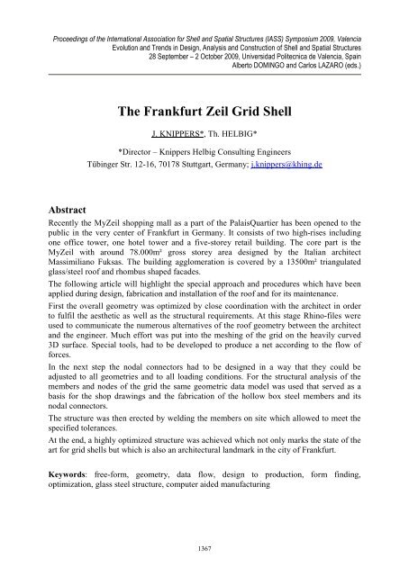
<strong>The</strong> <strong>Frankfurt</strong> <strong>Zeil</strong> <strong>Grid</strong> <strong>Shell</strong><br />
J. KNIPPERS*, Th. HELBIG*<br />
*Director – Knippers Helbig Consulting Engineers<br />
Tübinger Str. 12-16, 70178 Stuttgart, Germany; j.knippers@khing.de<br />
Abstract<br />
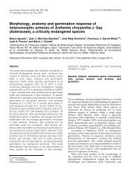
Recently the My<strong>Zeil</strong> shopping mall as a part of the PalaisQuartier has been opened to the<br />
public in the very center of <strong>Frankfurt</strong> in Germany. It consists of two high-rises including<br />
one office tower, one hotel tower and a five-storey retail building. <strong>The</strong> core part is the<br />
My<strong>Zeil</strong> with around 78.000m² gross storey area designed by the Italian architect<br />
Massimiliano Fuksas. <strong>The</strong> building agglomeration is covered by a 13500m² triangulated<br />
glass/steel roof and rhombus shaped facades.<br />
<strong>The</strong> following article will highlight the special approach and procedures which have been<br />
applied during design, fabrication and installation of the roof and for its maintenance.<br />
First the overall geometry was optimized by close coordination with the architect in order<br />
to fulfil the aesthetic as well as the structural requirements. At this stage Rhino-files were<br />
used to communicate the numerous alternatives of the roof geometry between the architect<br />
and the engineer. Much effort was put into the meshing of the grid on the heavily curved<br />
3D surface. Special tools, had to be developed to produce a net according to the flow of<br />
forces.<br />
In the next step the nodal connectors had to be designed in a way that they could be<br />
adjusted to all geometries and to all loading conditions. For the structural analysis of the<br />
members and nodes of the grid the same geometric data model was used that served as a<br />
basis for the shop drawings and the fabrication of the hollow box steel members and its<br />
nodal connectors.<br />
<strong>The</strong> structure was then erected by welding the members on site which allowed to meet the<br />
specified tolerances.<br />
At the end, a highly optimized structure was achieved which not only marks the state of the<br />
art for grid shells but which is also an architectural landmark in the city of <strong>Frankfurt</strong>.<br />
Keywords: free-form, geometry, data flow, design to production, form finding,<br />
optimization, glass steel structure, computer aided manufacturing<br />
1367
Proceedings of the International Association for <strong>Shell</strong> and Spatial Structures (IASS) Symposium 2009, Valencia<br />
Evolution and Trends in Design, Analysis and Construction of <strong>Shell</strong> and Spatial Structures<br />
1. Introduction<br />
Shopping malls are often understood as iconic buildings by modern architecture with<br />
expressive design and eye-catching shape. <strong>The</strong> relatively new design approach is often<br />
based on free form geometries which are encouraged by recently developed easy to handle<br />
3d-software tools being more and more introduced into the planning process.<br />
<strong>The</strong> role of the engineer is conceived as that of a mediator between the aesthetic ambitions<br />
of the architect, the budget of the client and the technical capabilities of the contractor.<br />
From the very early stages of form finding to the assembly on site, a consistent design<br />
process is absolutely necessary to achieve high quality free formed structures.<br />
Computer controlled fabrication methods allow for structures, which would not have been<br />
possible a few years ago. But how does one transfer 3D geometries into a load bearing<br />
structure without loosing the architectural vision of smoothly shaped building envelopes?<br />
2. Concept to erection<br />
Figure 1: Persepctive of retail building with roof<br />
For 3D-shaped buildings, grid shells are often used as a structural system. In the early days<br />
of grid shells, the limitations of fabrication were very strict. <strong>The</strong> number of members with<br />
different lengths or nodes with different angles had to be reduced to a minimum. <strong>The</strong><br />
methods of numerical analysis were also limited. Only geometries and meshes could be<br />
used, for which methods of structural analysis existed. <strong>The</strong>se technical restrictions limited<br />
the options for grid shells and led to certain standard types of construction systems and<br />
architectural forms for domes and other 3D-structures, which were used repeatedly.<br />
Neither fabrication nor structural analysis causes limitations for the design of free formed<br />
systems anymore. Due to Computer Aided Manufacturing (CAM) nearly every 3Dgeometry<br />
can be built. However, many examples can be found where an elegant 3D-shape<br />
was not transferred into a built structure accordingly. Irregular grids and rough construction<br />
details affect the structural integrity and the elegance of the architectural idea. <strong>The</strong> reason is<br />
1368
Proceedings of the International Association for <strong>Shell</strong> and Spatial Structures (IASS) Symposium 2009, Valencia<br />
Evolution and Trends in Design, Analysis and Construction of <strong>Shell</strong> and Spatial Structures<br />
often that the architectural design on one hand and the technical realization on the other are<br />
considered as two different tasks carried out subsequently by different people with different<br />
approaches and tools. While architects often work with 3D modelling tools, engineers use<br />
finite element analysis software with an interface to CAD applications. Thus even on a<br />
technical level, the communication between the aesthetic and the structural design is often<br />
difficult.<br />
To achieve an optimal solution for a grid shell, a continuous process of engineering from<br />
the very first architectural idea to the assembly on site is necessary. This process, the digital<br />
chain, basically consists of the following steps:<br />
- Optimizing shape and all-over geometry<br />
- Meshing<br />
- Design of nodal connectors<br />
- Structural analysis<br />
- Production and Erection<br />
<strong>The</strong> meshing of the grid, in particular, is a new design step which requires new tools. All<br />
steps need to be carried out carefully to achieve an optimal solution. <strong>The</strong> project My<strong>Zeil</strong> is<br />
an excellent example to this consistent process of design.<br />
2.1. Optimizing shape and over-all geometry<br />
Like a carpet, a grid shell covers the concrete slab levels. Figure 2 shows the first<br />
architectural vision of the geometry that we received as a ‘Rhino’ file. <strong>The</strong> geometry<br />
consists of flat areas, which are connected by sharply bent edges. <strong>The</strong> ‘canyon’ in the<br />
centre, which is above the shopping mall, is supposed to be column free for the comfort of<br />
the pedestrians. In the first design step, the 3D shape was optimized in two ways. First, the<br />
two horns, which were initially only aesthetic elements, were used as large columns, i.e. as<br />
structural elements. One is supported on the ground level and the other by the façade<br />
structure. <strong>The</strong>reafter, the sharp edges were smoothed to allow a flow of forces which<br />
enables shell-behaviour and reduces the bending moments in the steel members. Figure 3<br />
By doing so, a column free shopping-mall was achieved. <strong>The</strong> flat zones above the top<br />
levels are supported by columns with a regular spacing. At this stage of the design intense<br />
discussion between architects and engineers about geometries and shapes took place via the<br />
exchange of ‘Rhino’ files.<br />
1369
Proceedings of the International Association for <strong>Shell</strong> and Spatial Structures (IASS) Symposium 2009, Valencia<br />
Evolution and Trends in Design, Analysis and Construction of <strong>Shell</strong> and Spatial Structures<br />
2.2. Geometry meshing<br />
Figure 2: Original shape<br />
Figure 3: Optimized shape<br />
In the next design step, the 3D-shape had to be transferred into a structural grid. Due to the<br />
complex geometry a simple projection method could not be used in this case. Standardized<br />
methods and tools do not exist for this task. Often, automatic mesh generators from FEanalysis-<br />
or 3D modelling software are used. However, they usually do not lead to<br />
satisfying results. <strong>The</strong>se meshing tools start from the boundaries and connect separately<br />
generated zones, which leads to irregular meshes in the centre. This isn’t satisfying from<br />
neither an aesthetical nor structural point of view. Figure 4<br />
1370
Proceedings of the International Association for <strong>Shell</strong> and Spatial Structures (IASS) Symposium 2009, Valencia<br />
Evolution and Trends in Design, Analysis and Construction of <strong>Shell</strong> and Spatial Structures<br />
Figure 4: automatically generated mesh (left) and result with scripted tools (right)<br />
Figure 5: interior view of autogenerated mesh (left) and result with scripted tools (right)<br />
1371
Proceedings of the International Association for <strong>Shell</strong> and Spatial Structures (IASS) Symposium 2009, Valencia<br />
Evolution and Trends in Design, Analysis and Construction of <strong>Shell</strong> and Spatial Structures<br />
To achieve an orientation of the members which satisfies aesthetic as well as structural<br />
requirements ‘lines of orientation’ as well as connection points for the vertical façade were<br />
defined. <strong>The</strong>se were used as starting points or as boundary conditions for the mesh<br />
generation. Figure 6<br />
Figure 6: geometrical constraints and lines of orientation<br />
Next, the shape was divided in ‘mega-triangles’, which define the position of the 7-member<br />
nodes, which are unavoidable for such kind of geometries with strong boundary conditions.<br />
Within these ‘mega-triangles’ continuous nets with smaller triangles and 6-member nodes<br />
were generated. This procedure is similar to the one used by Buckminster Fuller for his<br />
geodetic domes. However, some manual adjustment was still needed. After several<br />
intermediate steps the grid in Figure 5 (right) was achieved, which served as a data-model<br />
for structural analysis and the shop drawings as well as for fabrication. <strong>The</strong> average<br />
member length is 2.30 m.<br />
1372
Proceedings of the International Association for <strong>Shell</strong> and Spatial Structures (IASS) Symposium 2009, Valencia<br />
Evolution and Trends in Design, Analysis and Construction of <strong>Shell</strong> and Spatial Structures<br />
2.4. Structural analysis<br />
<strong>The</strong> final grid geometry was transferred into a finite element model using transformation<br />
scripts. <strong>The</strong> orientation of each profile could be adjusted normal to the grid surface within<br />
the same step. Figure 7<br />
Figure 7: Finite element model of roof structure<br />
Wind and snow loads were investigated based on the complex geometry of the roof<br />
structure by a university institute (IFI FH Aachen).<br />
A detailed wind tunnel test has been undertaken to determine the distribution of wind loads.<br />
<strong>The</strong> PalaisQuartier project and its urban surroundings have been included in the wind<br />
tunnel model (scale 1:500). Wind pressure results were measured for 12 different wind<br />
directions. Due to the adjacent high-rise buildings areas of the roof structure were detected<br />
where wind pressure is concentrated.<br />
Furthermore, a snow load report has been carried out by the same institute locating and<br />
quantifying areas of snow drifts and quantifying them. Extremely inclined areas such as the<br />
canyon walls lead to snow concentration at the lower areas such as the canyon bottom or<br />
the base of the large column. Without additional technique such as snow guards especially<br />
the column base would have to bear a height of 12 m of snow slipped from the canyon<br />
walls.<br />
Finally, around 100 linear and non-linear load combinations have been calculated (using 3 rd<br />
order theory)in order to detect the maximum design stresses of each roof member. <strong>The</strong> shell<br />
structure consists of areas which are mainly under compression (e.g. large column) as well<br />
as those mainly under tension (e.g. canyon walls). For some regions linear calculation leads<br />
to conservative results while in others non-linear effects have to be considered. Each<br />
section has been optimized to its worst load combination.<br />
1373
Proceedings of the International Association for <strong>Shell</strong> and Spatial Structures (IASS) Symposium 2009, Valencia<br />
Evolution and Trends in Design, Analysis and Construction of <strong>Shell</strong> and Spatial Structures<br />
2.3. Design of nodal connectors<br />
<strong>The</strong> transformation of the data model into a built structure depends very much on the<br />
experience of the contractor and the means of fabrication. <strong>The</strong>re is no standardized solution<br />
for the nodal points of the grid. In contrast to the roof for the trade fair in Milano, which<br />
was also designed by Massimilano Fuksas, the architect wanted an aesthetically<br />
unobtrusive detail for the nodal connector.<br />
For this structure the contractor (Waagner Biro, Vienna, Austria) proposed a welded<br />
connection for the node, which is based on the experience that he had gained for the roof<br />
over the courtyard of the British museum in London Figure 8. <strong>The</strong> beam members are<br />
welded to a central ‘star’, which is burned out of a thick steel plate. However, due to the<br />
complex geometry about 10% of all nodes are fabricated as a compact steel block. <strong>The</strong><br />
node geometry is developed in a way that the centre lines on top of the steel members meet<br />
in the node (the same holds for the Westfield project in London). <strong>The</strong> members are welded<br />
hollow box sections with an average size of 120x 60 mm. <strong>The</strong> thicknesses of the plates are<br />
adapted to the respective loading conditions.<br />
Figure 8: nodal connector of My<strong>Zeil</strong> (Waagner Biro)<br />
For the structural analysis of the node plates the individual stress condition at each position<br />
is considered. Anyway, their complex geometry has been simplified to a perfect planar<br />
hexagonal system which allowed for a generalized calculation method. Since vertical and<br />
torsional rotation angles of the beams have an important influence on the node balance and<br />
on the stress distribution additional coefficients are introduced to adjust the simplified<br />
results. Finite element models of all individual node geometries could be avoided by these<br />
1374
Proceedings of the International Association for <strong>Shell</strong> and Spatial Structures (IASS) Symposium 2009, Valencia<br />
Evolution and Trends in Design, Analysis and Construction of <strong>Shell</strong> and Spatial Structures<br />
simplifications. However, some major geometrical cases have been investigated using FE<br />
models to determine the coefficients and for a better understanding of the distribution of<br />
forces. Figure 9, Figure 10<br />
Figure 9: Finite element model of node with eccentrically connected diagonals<br />
Figure 10: Finite element model of standard roof node (upper flange)<br />
Within the generalized calculation method only the flanges of each beam connected to the<br />
node are considered to transfer internal forces. <strong>The</strong>y are fixed to each other (upper flange)<br />
or to the central ‘star’ (lower flange) by full penetration butt welds. <strong>The</strong> webs are neglected<br />
for the load transfer and fixed by nominal fillet welds.<br />
1375
Proceedings of the International Association for <strong>Shell</strong> and Spatial Structures (IASS) Symposium 2009, Valencia<br />
Evolution and Trends in Design, Analysis and Construction of <strong>Shell</strong> and Spatial Structures<br />
2.5. Production and Erection<br />
<strong>The</strong> gridshell is divided into manageable pieces forming ladders. <strong>The</strong> ladders were<br />
prefabricated in the workshop. On site they were lifted into position and connected to the<br />
adjacent structure by inserting and welding the lose members. A spatial scaffolding<br />
supported the structure during erection and allowed to adjust the position of nodes<br />
according to the required tolerances. Figure 11, Figure 12<br />
Figure 11: grid during construction<br />
1376
Proceedings of the International Association for <strong>Shell</strong> and Spatial Structures (IASS) Symposium 2009, Valencia<br />
Evolution and Trends in Design, Analysis and Construction of <strong>Shell</strong> and Spatial Structures<br />
Figure 12: grid during construction<br />
2.6. Cleaning concept<br />
Depending on the location and orientation of each glazed surface of the roof structure<br />
convenient cleaning methods have been developed. For vertical surfaces such as vertical<br />
facades a portable hoisting platform will be used. Horizontal or inclined surfaces of the<br />
canyon roof will be cleaned by a special ‘Cat Wash’ vehicle with brushes operated by<br />
remote-control. Figure 13<br />
Figure 13: CatWash façade cleaning vehicle (pictures by TAW)<br />
1377
Proceedings of the International Association for <strong>Shell</strong> and Spatial Structures (IASS) Symposium 2009, Valencia<br />
Evolution and Trends in Design, Analysis and Construction of <strong>Shell</strong> and Spatial Structures<br />
<strong>The</strong> large glazed column is difficult to clean by common methods. <strong>The</strong>refore, an element<br />
called ‘air-beam’ has been developed by TAW. Hidden below the bottom plate of the large<br />
column it will be blown up for the cleaning process. To control the beam it is fixed at three<br />
points in the upper part of the roof, and rotating brushes move up and down. Figure 14<br />
Figure 14: AirBeam cleaning system for large glazed column (figure by TAW)<br />
References<br />
[1] Crisfield M.A., Non-linear Finite Element Analysis of Solids and Structures. Volume<br />
2: Advanced Topics. (2 nd ed.), Wiley, 1997.<br />
[2] Falk A. and Samuelsson S., Timber plates in tensile structures, in IASS 2004. <strong>Shell</strong><br />
and Spatial Structures from Models to Realization, Motro R (ed.), Editions de<br />
l’Esperou, 2004, 254-255.<br />
[3] Winslow P., Pellegrino S. and Sharma S.B., Mapping two-way grids onto free-form<br />
surfaces. Journal of the International Association for <strong>Shell</strong> and Spatial Structures,<br />
2008; 49; 123-130.<br />
1378