SECTION 033000 - CAST-IN-PLACE CONCRETE
SECTION 033000 - CAST-IN-PLACE CONCRETE
SECTION 033000 - CAST-IN-PLACE CONCRETE

Create successful ePaper yourself
Turn your PDF publications into a flip-book with our unique Google optimized e-Paper software.
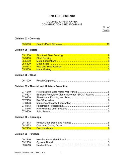
Division 03 - Concrete<br />
TABLE OF CONTENTS<br />
MODIFIED K WEST ANNEX<br />
CONSTRUCTION SPECIFICATIONS<br />
44577-CSI-SPEC-001, Rev D & E i<br />
No. of<br />
Pages<br />
03 3000 Cast-In-Place Concrete ................................................................. 19<br />
Division 05 - Metals<br />
05 1200 Structural Steel Framing ................................................................. 9<br />
05 3100 Steel Decking .................................................................................. 5<br />
05 5000 Metal Fabrications ........................................................................... 8<br />
05 5100 Metal Stairs ..................................................................................... 7<br />
05 5213 Pipe and Tube Railings ................................................................... 4<br />
05 5300 Metal Grating................................................................................... 3<br />
Division 06 - Wood<br />
06 1000 Rough Carpentry ............................................................................. 2<br />
Division 07 - Thermal and Moisture Protection<br />
07 4219 Fire Resistive-Core Metal Wall Panels ............................................ 6<br />
07 5323 Ethylene-Propylene-Diene-Monomer (EPDM) Roofing ................... 6<br />
07 6200 Sheet Metal Flashing and Trim ....................................................... 4<br />
07 7100 Roof Specialties .............................................................................. 6<br />
07 8123 Intumescent Mastic Fireproofing ..................................................... 4<br />
07 8413 Penetration Firestopping ................................................................. 9<br />
07 8446 Fire-Resistive Joint Systems ........................................................... 4<br />
07 9200 Joint Sealant ................................................................................... 5<br />
Division 08 - Openings<br />
08 1113 Hollow Metal Doors and Frames ..................................................... 6<br />
08 3323 Overhead Coiling Doors .................................................................. 6<br />
08 7100 Door Hardware ................................................................................ 9<br />
Division 09 - Finishes<br />
09 2216 Non-Structural Metal Framing ......................................................... 3<br />
09 2900 Gypsum Board ................................................................................ 3<br />
09 6513 Resilient Base ................................................................................. 3
09 9113 Exterior Painting .............................................................................. 4<br />
09 9123 Interior Painting ............................................................................... 5<br />
09 9600 High-Performance Coatings ............................................................ 7<br />
Division 10 - Specialties<br />
10 1400 Signage ........................................................................................... 4<br />
10 4413 Fire Extinguisher Cabinets .............................................................. 3<br />
10 4416 Fire Extinguishers ........................................................................... 3<br />
10 5113 Metal Lockers .................................................................................. 7<br />
Division 11 - Equipment<br />
11 1300 Loading Dock Equipment ................................................................ 2<br />
Division 21 – Fire Suppression<br />
21 1220 Storage Tanks ................................................................................. 3<br />
21 1313 Wet-Pipe Sprinkler System ........................................................... 14<br />
Division 22 – Plumbing<br />
22 0523 General Duty Valves for Plumbing Piping ....................................... 5<br />
22 0529 Hangers and Supports for Plumbing Piping and Equipment ........... 7<br />
22 0533 Heat Tracing for Plumbing Piping ................................................... 4<br />
22 0548 Vibration and Seismic Controls for Plumbing Piping<br />
and Equipment................................................................................ 8<br />
22 0553 Identification for Plumbing Piping and Equipment ........................... 6<br />
22 1329 Sanitary Sewerage Pumps (Fire Water Drainage Lift Station) ...... 10<br />
22 1413 Facility Storm Drainage Piping (Fire Water Drainage) .................. 13<br />
22 1513 General Service Compressed Air Piping ....................................... 32<br />
22 1519 General Service Packaged Air-Compressors and Receivers ........ 13<br />
22 6313 Nitrogen Gas Piping ...................................................................... 33<br />
Division 23 – Heating Ventilating and Air Conditioning<br />
23 0513 Common Motor Requirements for HVAC Equipment ...................... 3<br />
23 0519 Meter and Gages for HVAC Piping ................................................. 5<br />
23 0523 General Duty Valves for HVAC Piping ............................................ 6<br />
23 0529 Hangers and Supports for HVAC Piping and Equipment ................ 8<br />
23 0548 Vibration and Seismic Controls for HVAC Piping Equipment .......... 7<br />
23 0553 Identification for HVAC Piping and Equipment ................................ 6<br />
23 0593 Testing, Adjusting, and Balancing for HVAC ................................. 22<br />
23 0700 HVAC Insulation ............................................................................ 21<br />
23 0900 Instrumentation and Control for HVAC .......................................... 19<br />
23 0993 Sequence of Operations for HVAC Controls ................................. 20<br />
23 2113 Hydronic Piping ............................................................................. 15<br />
44577-CSI-SPEC-001, Rev D & E ii
23 2123 Hydronic Pumps .............................................................................. 4<br />
23 3113 Metal Ducts ................................................................................... 15<br />
23 3300 Air Duct Accessories ..................................................................... 12<br />
23 3713 Diffusers, Registers, and Grilles ...................................................... 4<br />
23 4100 Particulate Air Filtration ................................................................... 3<br />
23 5100 Breachings and Stacks ................................................................... 3<br />
23 5213 Electric Boilers ................................................................................ 7<br />
23 6423 Scroll Heat Pump Chillers ............................................................... 9<br />
23 7313 Modular Indoor, Central-Station Air Handling Units ....................... 16<br />
Division 26 - Electrical<br />
26 0513 Medium-Voltage Cables .................................................................. 5<br />
26 0519 Low-Voltage Electrical Power Conductors and Cables ................... 7<br />
26 0523 Control-Voltage Electrical Power Cables ........................................ 5<br />
26 0526 Grounding and Bonding for Electrical Systems ............................... 6<br />
26 0529 Hangers and Supports for Electrical Systems ................................. 5<br />
26 0533 Raceway and Boxes for Electrical Systems .................................... 9<br />
26 0536 Cable Trays for Electrical Systems ................................................. 4<br />
26 0543 Underground Ducts and Raceways for Electrical Systems ............. 7<br />
26 0548 Vibration and Seismic Controls for Electrical Systems .................... 6<br />
26 0553 Identification for Electrical Systems ................................................. 7<br />
26 1200 Medium-Voltage Transformers ........................................................ 7<br />
26 2200 Low-Voltage Transformers .............................................................. 5<br />
26 2416 Panelboards .................................................................................. 10<br />
26 2713 Electricity Metering .......................................................................... 3<br />
26 2726 Wiring Devices ................................................................................ 5<br />
26 2816 Enclosed Switches and Circuit Breakers ......................................... 6<br />
26 2913 Enclosed Controllers ....................................................................... 6<br />
26 2923 Variable-Frequency Motor Controllers ............................................ 9<br />
26 4313 Transient- Voltage Suppression for Low-Voltage<br />
Electrical Power Circuits ................................................................. 5<br />
26 5100 Interior Lighting ............................................................................... 7<br />
26 5600 Exterior Lighting .............................................................................. 5<br />
Division 27 - Communications<br />
27 1000 Communications Horizontal Cabling ............................................... 5<br />
Division 28 – Electronic Safety and Security<br />
28 2300 Video Surveillance .......................................................................... 9<br />
28 3100 Fire Detection and Alarm .............................................................. 20<br />
28 3233 Radiation Detection and Alarm ....................................................... 3<br />
44577-CSI-SPEC-001, Rev D & E iii
Division 31 - Earthwork<br />
31 1000 Site Clearing ................................................................................... 3<br />
31 2000 Earth Moving ................................................................................... 8<br />
Division 32 – Exterior Improvements<br />
32 1216 Asphalt Paving ................................................................................ 5<br />
Division 33 – Utilities<br />
33 1116 Facility Water Distribution Piping ..................................................... 5<br />
Division 40 – Process Integration<br />
40 0511 Compression Fittings on Copper and Stainless Steel Tubing ....... 19<br />
40 0527 Piping and Tubing Inspection Checklist .......................................... 6<br />
40 2319 Process Plant Non-Potable Water Pipe (Modified for IXM) ........... 27<br />
Division 43 – Process Gas and Liquid Handling, Purification and Storage<br />
Equipment<br />
43 1510 Low Pressure Air Purge Piping ..................................................... 28<br />
Revision D (no highlighting)<br />
Revision E (yellow highlighting)<br />
44577-CSI-SPEC-001, Rev D & E iv
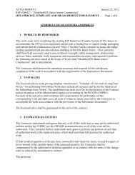
Sludge Treatment Project Engineered Container Retrieval and Transfer System January 2012<br />
<strong>SECTION</strong> <strong>033000</strong> - <strong>CAST</strong>-<strong>IN</strong>-<strong>PLACE</strong> <strong>CONCRETE</strong><br />
PART 1 - GENERAL<br />
1.1 SUMMARY<br />
A. Section includes cast-in-place concrete, including formwork, reinforcement, concrete materials,<br />
mixture design, placement procedures, and finishes.<br />
B. Related Sections:<br />
1. Division 05 Section “Metal Fabrications” for embedded items.<br />
2. Division 31 Section “Earth Moving” for drainage fill under slabs-on-grade.<br />
1.2 ACTION SUBMITTALS<br />
A. Product Data: For each type of product indicated.<br />
B. Design Mixtures: For each concrete mixture. Submit alternate design mixtures when<br />
characteristics of materials, Project conditions, weather, test results, or other circumstances<br />
warrant adjustments.<br />
1. Indicate amounts of mixing water to be withheld for later addition at Project site.<br />
2. Provide documentation of design compressive strength per ACI 301.<br />
C. Steel Reinforcement Shop Drawings: Placing drawings that detail fabrication, bending, and<br />
placement. Include bar sizes, lengths, material, grade, bar schedules, stirrup spacing, bent bar<br />
diagrams, bar arrangement, splices and laps, mechanical connections, tie spacing, hoop spacing,<br />
and supports for concrete reinforcement.<br />
D. Wall Formwork Shop Drawings: Prepared by or under the supervision of a qualified<br />
professional engineer detailing fabrication, assembly, and support of formwork. Drawings shall<br />
be stamped by a Washington state licensed engineer.<br />
E. Wall Formwork Calculations: Prepared by or under the supervision of a qualified professional<br />
engineer for support of formwork. Calculations shall be stamped by a Washington state<br />
licensed engineer.<br />
F. Construction Joint Layout: Indicate proposed construction joints required to construct the<br />
structure.<br />
1. Location of construction joints is subject to approval of the Buyer’s Technical<br />
Representative.<br />
G. Welding Procedure Specifications (WPSs) and Procedure Qualification Records (PQRs):<br />
Provide according to AWS D1.4/D 1.4M, “Structural Welding Code - Reinforcing Steel” for<br />
each welded joint qualified by testing, including the following:<br />
Contract 44577 KW Annex - Rev. E 44577-CSI-SPEC-001 <strong>033000</strong> - 1
Sludge Treatment Project Engineered Container Retrieval and Transfer System January 2012<br />
1. Power source (constant current or constant voltage).<br />
2. Electrode manufacturer and trade name, for demand critical welds.<br />
H. Manufacturer Qualifications.<br />
I. Repair Methods: Per ACI 301 5.1.2.<br />
J. Finisher Qualifications for Finisher Contractor and Finishers per ACI 301 5.1.2.<br />
K. Testing Agency Qualifications including field personnel.<br />
1. Personnel conducting field tests shall be qualified as ACI Concrete Field Testing<br />
Technician, Grade 1, according to ACI CP-1 or a similar certification program or through<br />
experience and training.<br />
1.3 <strong>IN</strong>FORMATIONAL SUBMITTALS<br />
A. Welding certificates.<br />
B. Material certificates: For each of the following, signed by manufacturers:<br />
1. Cementitious materials.<br />
2. Admixtures.<br />
3. Steel reinforcement.<br />
4. Fiber reinforcement.<br />
5. Waterstops.<br />
6. Curing compounds.<br />
7. Bonding agents.<br />
8. Adhesives.<br />
9. Joint-filler strips.<br />
10. Repair materials.<br />
C. Material test reports: For the following, from a qualified testing agency, indicating compliance<br />
with requirements:<br />
1. Aggregates.<br />
D. Field quality-control reports: For the following, from the Contractor, indicating compliance<br />
with requirements:<br />
1. Concrete Pour Checklist.<br />
2. Batch ticket.<br />
E. Field quality-control reports: For the following, from a qualified testing agency, indicating<br />
compliance with requirements:<br />
1. Steel reinforcement placement.<br />
2. Steel reinforcement welding.<br />
3. Headed bolts and studs.<br />
4. Verification of use of required design mixture.<br />
Contract 44577 KW Annex - Rev. E 44577-CSI-SPEC-001 <strong>033000</strong> - 2
Sludge Treatment Project Engineered Container Retrieval and Transfer System January 2012<br />
5. Concrete placement, including conveying and depositing.<br />
6. Curing procedures and maintenance of curing temperature.<br />
7. Composite Sample (Slump, Air Content, Concrete Temperature) Tests.<br />
8. Unit Weight Tests.<br />
9. Compressive-Strength Tests.<br />
F. Conveying Equipment: Per ACI 301 5.1.2.<br />
G. Temperature Measurements: Per ACI 301 5.1.2.<br />
H. Floor surface flatness and levelness measurements.<br />
I. Minutes of preinstallation conference.<br />
1.4 QUALITY ASSURANCE<br />
A. Manufacturer Qualifications: A firm experienced in manufacturing ready-mixed concrete<br />
products and that complies with ASTM C 94/C 94M requirements for production facilities and<br />
equipment.<br />
1. Manufacturer certified according to NRMCA’s “Certification of Ready Mixed Concrete<br />
Production Facilities”.<br />
B. Testing Agency Qualifications: An independent agency, qualified according to ASTM C 1077<br />
and ASTM E 329 for testing indicated.<br />
C. For fire resistance, concrete walls in the Loading Bay are Safety Significant, SSC’s (Structure<br />
Systems or Components) as shown on the drawings.<br />
1. All safety SSCs will be procured, inspected, accepted, and verified in accordance with the<br />
requirements of PRC-MP-QA-599, Quality Assurance Program.<br />
2. The critical characteristics are:<br />
a. Concrete wall shall be 4.6” minimum thickness<br />
b. Cover for reinforcing shall be 3/4” minimum.<br />
c. Wall shall be reinforced with #4 at 18” each way, each face.<br />
D. For wind and seismic resistance, concrete (walls and foundations directly under the walls) in the<br />
Loading Bay is Safety Significant, SSC’s (Structure Systems or Components) as shown on the<br />
drawings.<br />
1. All safety SSCs will be procured, inspected, accepted, and verified in accordance with the<br />
requirements of PRC-MP-QA-599, Quality Assurance Program.<br />
2. Critical characteristics apply to the concrete (walls and foundations directly under the<br />
walls) as well as all embedded items shown on the structural drawings, including, but not<br />
limited to, reinforcing, steel embeds, anchor bolts, and anchor rods, etc., except for the<br />
embedded strut.<br />
3. The critical characteristics are:<br />
a. Concrete compressive strength<br />
Contract 44577 KW Annex - Rev. E 44577-CSI-SPEC-001 <strong>033000</strong> - 3
Sludge Treatment Project Engineered Container Retrieval and Transfer System January 2012<br />
b. Reinforcing yield strength<br />
c. Placement of concrete and reinforcing per ACI 117<br />
d. For embedded steel items, see section 05.<br />
E. Concrete hose-in-hose chase in the HEPA room and exterior is Safety Significant, SSC’s<br />
(Structure Systems or Components) as shown on the drawings.<br />
1. All safety SSCs will be procured, inspected, accepted, and verified in accordance with the<br />
requirements of PRC-MP-QA-599, Quality Assurance Program.<br />
2. The critical characteristics are:<br />
a. Concrete compressive strength<br />
b. Reinforcing yield strength<br />
c. Placement of concrete and reinforcing per ACI 117<br />
F. Slope of exterior slab to east of the Loading Bay is Safety Significant, SSC’s (Structure Systems<br />
or Components) as shown on the drawings.<br />
1. All safety SSCs will be procured, inspected, accepted, and verified in accordance with the<br />
requirements of PRC-MP-QA-599, Quality Assurance Program.<br />
2. The critical characteristic is slope. The slab shall slope away from the building a<br />
minimum of 1% for at least 10 feet.<br />
G. For fire resistance, concrete roof in the Loading Bay is Safety Significant, SSC’s (Structure<br />
Systems or Components) as shown on the drawings.<br />
1. All safety SSCs will be procured, inspected, accepted, and verified in accordance with the<br />
requirements of PRC-MP-QA-599, Quality Assurance Program.<br />
2. The critical characteristics are:<br />
a. Lightweight concrete shall consist of a combination of expanded clay, shale, slag,<br />
slate, sintered fly ash, and/or any natural lightweight aggregrate meeting ASTM<br />
C330 and natural sand. Unit weight shall be between 105 pcf and 120 pcf.<br />
b. Equation 7-3 of IBC 2006 shall be equal or greater than 2.7”. For minimum<br />
thickness over top of flutes of 2 1/2”, minimum total thickness of roof of 4”, and<br />
metal deck rib spacing of 6”, Equation 7-3 equal 2.8”.<br />
c. Cover for reinforcing shall be 3/4” minimum, both from top surface and above<br />
metal deck.<br />
H. For Wind and Seismic resistance, concrete roof in the Loading Bay is Safety Significant, SSC’s<br />
(Structure Systems or Components) as shown on the drawings.<br />
1. All safety SSCs will be procured, inspected, accepted, and verified in accordance with the<br />
requirements of PRC-MP-QA-599, Quality Assurance Program.<br />
2. The critical characteristics are:<br />
a. Concrete compressive strength<br />
b. Reinforcing yield strength<br />
c. Placement of concrete and reinforcing per ACI 117<br />
Contract 44577 KW Annex - Rev. E 44577-CSI-SPEC-001 <strong>033000</strong> - 4
Sludge Treatment Project Engineered Container Retrieval and Transfer System January 2012<br />
I. ACI Publications: Comply with the following unless modified by requirements in the Contract<br />
Documents:<br />
1. ACI 301, “Specifications for Structural Concrete”, Sections 1 through 5 and Section 7,<br />
“Lightweight Concrete”.<br />
2. ACI 117, “Specifications for Tolerances for Concrete Construction and Materials”.<br />
3. ACI 211.1, “Standard Practice for Selecting Proportions for Normal, Heavyweight, and<br />
Mass Concrete”.<br />
4. ACI 211.2, “Standard Practice for Selecting Proportions for Structural Lightweight<br />
Concrete”.<br />
5. ACI 305R, “Hot Weather Concreting”.<br />
6. ACI 306R, “Cold Weather Concreting”.<br />
J. Concrete Testing Service: Engage a qualified independent testing agency to perform material<br />
evaluation tests and to design concrete mixtures.<br />
K. Mockups: Cast structural lightweight concrete mixture on metal deck to demonstrate surface<br />
finish, texture, tolerances, unit weight, compressive strength, delivery time, conveying and<br />
standard of workmanship.<br />
1. Build panel approximately 100 sq. ft. in the location near indicated by Buyer’s Technical<br />
Representative. Deck shall have supports at 5’ centers and be at least two spans. Metal<br />
deck shall be same used for roofing. Deck need not be anchored to the supports.<br />
2. Mockup may be near ground level but shall be conveyed as will be done for roof decks.<br />
3. Mockup may be removed after approval including 28 day test reports.<br />
L. Preinstallation Conference: Conduct conference at Project site.<br />
1. Before submitting design mixtures, review concrete design mixture and examine<br />
procedures for ensuring quality of concrete materials. Require representatives of each<br />
entity directly concerned with cast-in-place concrete to attend, including the following:<br />
a. Contractor's superintendent.<br />
b. Independent testing agency responsible for concrete design mixtures.<br />
c. Ready-mix concrete manufacturer.<br />
d. Concrete subcontractor.<br />
2. Coordinate meeting. Request the following representatives to attend:<br />
a. BTR<br />
b. CHPRC Construction Manager.<br />
c. CHPRC QC.<br />
d. Structural Engineer.<br />
3. Review special inspection and testing and inspecting agency procedures for field quality<br />
control, concrete finishes and finishing, cold and hot-weather concreting procedures, fall<br />
protection, lifts, critical lifts, curing procedures, construction contraction and isolation<br />
joints, and joint-filler strips, forms and form removal limitations, shoring and reshoring<br />
procedures, vapor-retarder installation, anchor rod and anchorage device installation<br />
Contract 44577 KW Annex - Rev. E 44577-CSI-SPEC-001 <strong>033000</strong> - 5
Sludge Treatment Project Engineered Container Retrieval and Transfer System January 2012<br />
tolerances, steel reinforcement installation, floor and slab flatness and levelness<br />
measurement, concrete repair procedures, and concrete protection.<br />
1.5 DELIVERY, STORAGE, AND HANDL<strong>IN</strong>G<br />
A. Steel Reinforcement: Deliver, store, and handle steel reinforcement to prevent bending and<br />
damage.<br />
B. Waterstops: Store waterstops under cover to protect from moisture, sunlight, dirt, oil, and other<br />
contaminants.<br />
PART 2 - PRODUCTS<br />
2.1 FORM-FAC<strong>IN</strong>G MATERIALS<br />
A. Smooth-Formed Finished Concrete: Form-facing panels that will provide continuous, true, and<br />
smooth concrete surfaces. Furnish in largest practicable sizes to minimize number of joints.<br />
B. Rough-Formed Finished Concrete: Plywood, lumber, metal, or another approved material.<br />
Provide lumber dressed on at least two edges and one side for tight fit.<br />
C. Chamfer Strips: Wood, metal, PVC, or rubber strips, 3/4 by 3/4 inch, minimum.<br />
D. Form-Release Agent: Commercially formulated form-release agent that will not bond with,<br />
stain, or adversely affect concrete surfaces and will not impair subsequent treatments of<br />
concrete surfaces.<br />
1. Formulate form-release agent with rust inhibitor for steel form-facing materials.<br />
E. Form Ties: Factory-fabricated, removable or snap-off metal or glass-fiber-reinforced plastic<br />
form ties designed to resist lateral pressure of fresh concrete on forms and to prevent spalling of<br />
concrete on removal.<br />
1. Furnish units that will leave no corrodible metal closer than one inch to the plane of<br />
exposed concrete surface.<br />
2. Furnish ties that, when removed, will leave holes no larger than one inch in diameter in<br />
concrete surface.<br />
2.2 STEEL RE<strong>IN</strong>FORCEMENT<br />
A. Recycled Content of Steel Products: Provide products with an average recycled content of steel<br />
products so postconsumer recycled content plus one-half of preconsumer recycled content is not<br />
less than 60 percent. No documentation is required since The Steel Recycling Institute indicates<br />
that reinforcing bars are made by the electric arc furnace method, which typically has 57.5<br />
percent postconsumer recycled content and 6.5 percent preconsumer recycled content.<br />
B. Reinforcing Bars: ASTM A 615/A 615M, Grade 60, deformed.<br />
Contract 44577 KW Annex - Rev. E 44577-CSI-SPEC-001 <strong>033000</strong> - 6
Sludge Treatment Project Engineered Container Retrieval and Transfer System January 2012<br />
C. Low-Alloy-Steel Reinforcing Bars: ASTM A 706/A 706M, deformed.<br />
D. Plain-Steel Welded Wire Reinforcement: ASTM A 185/A 185M, plain, fabricated from asdrawn<br />
steel wire into flat sheets.<br />
E. Deformed-Steel Welded Wire Reinforcement: ASTM A 497/A 497M, flat sheet.<br />
F. Bar Supports: Bolsters, chairs, spacers, and other devices for spacing, supporting, and fastening<br />
reinforcing bars and welded wire reinforcement in place. Manufacture bar supports from steel<br />
wire, plastic, or precast concrete according to CRSI's “Manual of Standard Practice”.<br />
2.3 RE<strong>IN</strong>FORCEMENT ACCESSORIES<br />
A. Joint Dowel Bars: ASTM A 615/A 615M, Grade 60, plain-steel bars, cut true to length with<br />
ends square and free of burrs.<br />
B. Bar Supports: Bolsters, chairs, spacers, and other devices for spacing, supporting, and fastening<br />
reinforcing bars and welded wire reinforcement in place. Manufacture bar supports from steel<br />
wire, plastic, or precast concrete according to CRSI’s “Manual of Standard Practice”, of greater<br />
compressive strength than concrete and as follows:<br />
1. For concrete surfaces exposed to view where legs of wire bar supports contact forms, use<br />
CRSI Class 1 plastic-protected steel wire or CRSI Class 2 stainless-steel bar supports.<br />
C. Tie Wire: ASTM A853 carbon steel, 16 gage minimum.<br />
2.4 <strong>CONCRETE</strong> MATERIALS<br />
A. Cementitious Material: Use the following cementitious materials, of the same type, brand, and<br />
source, throughout Project:<br />
1. Portland Cement: ASTM C 150, Type I, Type II, or Type I/II. Supplement with the<br />
following:<br />
a. Fly Ash: ASTM C 618, Class F.<br />
B. Normal-Weight Aggregates: ASTM C 33, graded.<br />
1. Maximum Coarse-Aggregate Size: 1 1/2 inches nominal.<br />
2. Fine Aggregate: Free of materials with deleterious reactivity to alkali in cement.<br />
C. Lightweight Aggregate: ASTM C 330, 3/4 inch nominal maximum aggregate size.<br />
D. Water: ASTM C 94/C 94M and potable.<br />
2.5 ADMIXTURES<br />
A. Air-Entraining Admixture: ASTM C 260.<br />
Contract 44577 KW Annex - Rev. E 44577-CSI-SPEC-001 <strong>033000</strong> - 7
Sludge Treatment Project Engineered Container Retrieval and Transfer System January 2012<br />
B. Chemical Admixtures: Provide admixtures certified by manufacturer to be compatible with<br />
other admixtures and that will not contribute water-soluble chloride ions exceeding those<br />
permitted in hardened concrete. Do not use calcium chloride or admixtures containing calcium<br />
chloride.<br />
1. Water-Reducing Admixture: ASTM C 494/C 494M, Type A.<br />
2. Retarding Admixture: ASTM C 494/C 494M, Type B.<br />
3. Water-Reducing and Retarding Admixture: ASTM C 494/C 494M, Type D.<br />
4. High-Range, Water-Reducing Admixture: ASTM C 494/C 494M, Type F.<br />
5. Plasticizing and Retarding Admixture: ASTM C 1017/C 1017M, Type II.<br />
2.6 FIBER RE<strong>IN</strong>FORCEMENT<br />
A. Synthetic Micro-Fiber: Polypropylene micro-fibers engineered and designed for use in<br />
concrete, complying with ASTM C 1116/C 1116M, Type III, 1/2 to 1-1/2 inches<br />
2.7 WATERSTOPS<br />
A. Self-Expanding Butyl Strip Waterstops: Manufactured rectangular or trapezoidal strip, butyl<br />
rubber with sodium bentonite or other hydrophilic polymers, for adhesive bonding to concrete,<br />
3/4 by 1 inch.<br />
2.8 VAPOR RETARDERS<br />
A. Sheet Vapor Retarder: ASTM E 1745, Class A. Include manufacturer’s recommended<br />
adhesive or pressure-sensitive tape.<br />
1. Not less than 12 mils thick.<br />
2.9 CUR<strong>IN</strong>G MATERIALS<br />
A. Evaporation Retarder: Waterborne, monomolecular film forming, manufactured for application<br />
to fresh concrete.<br />
B. Absorptive Cover: AASHTO M 182, Class 2, burlap cloth made from jute or kenaf, weighing<br />
approximately 9 oz/sq. yd. when dry.<br />
C. Moisture-Retaining Cover: ASTM C 171, polyethylene film or white burlap-polyethylene<br />
sheet.<br />
D. Water: Potable.<br />
E. Clear, Waterborne, Membrane-Forming Curing and Sealing Compound: ASTM C 1315,<br />
Type 1, Class A, certified by curing compound manufacturer to not interfere with bonding of<br />
floor covering or coatings.<br />
Contract 44577 KW Annex - Rev. E 44577-CSI-SPEC-001 <strong>033000</strong> - 8
Sludge Treatment Project Engineered Container Retrieval and Transfer System January 2012<br />
2.10 RELATED MATERIALS<br />
A. Expansion- and Isolation-Joint-Filler Strips: ASTM D 1751, asphalt-saturated cellulosic fiber.<br />
B. Bonding Agent: ASTM C 1059/C 1059M, Type II, non-redispersible, acrylic emulsion or<br />
styrene butadiene.<br />
2.11 <strong>CONCRETE</strong> MIXTURES<br />
A. Prepare design mixtures for each type and strength of concrete, proportioned on the basis of<br />
laboratory trial mixture or field test data, or both, according to ACI 301 and ACI 211.1, or ACI<br />
211.2.<br />
B. Cementitious Materials: Use fly ash to reduce the total amount of portland cement, which<br />
would otherwise be used, by not more than 20 percent.<br />
C. Admixtures: Use admixtures according to manufacturer’s written instructions.<br />
1. Use water-reducing, high-range water-reducing and/or plasticizing admixture in concrete,<br />
as required, for placement and workability.<br />
2. Use water-reducing and retarding admixture when required by high temperatures, low<br />
humidity, or other adverse placement conditions.<br />
3. Use water-reducing admixture in pumped concrete, concrete for heavy-use industrial<br />
slabs and parking structure slabs, concrete required to be watertight, and concrete with a<br />
water-cementitious materials ratio below 0.50.<br />
D. All concrete except where Lean or Lightweight concrete called out on drawings: Proportion<br />
normal-weight concrete mixture as follows:<br />
1. Minimum Compressive Strength: 4,000 psi at 28 days.<br />
2. Maximum Water-Cementitious Materials Ratio: 0.50.<br />
3. Slump Limit: 7 inches for concrete with verified slump of 2 to 4 inches before adding<br />
high-range water-reducing admixture or plasticizing admixture, plus or minus 1 inch.<br />
4. Air Content: 5.5 percent, plus or minus 1.5 percent at point of delivery for 1 1/2 inch<br />
nominal maximum aggregate size.<br />
5. Air Content: 6 percent, plus or minus 1.5 percent at point of delivery for 1 inch or less<br />
nominal maximum aggregate size.<br />
6. Air Content: Do not allow air content of trowel-finished floors to exceed 3 percent.<br />
7. Synthetic Micro-Fiber: Uniformly disperse in concrete mixture at manufacturer's<br />
recommended rate, but not less than 1.0 lb/cu. yd.<br />
E. Lean Concrete: Proportion normal-weight concrete mixture as follows:<br />
1. Minimum Compressive Strength: 2,500 psi at 28 days.<br />
2. Slump Limit: 7 inches for concrete with verified slump of 2 to 4 inches before adding<br />
high-range water-reducing admixture or plasticizing admixture, plus or minus 1 inch.<br />
3. Air Content: 5.5 percent, plus or minus 1.5 percent at point of delivery for 1 1/2 inch<br />
nominal maximum aggregate size.<br />
4. Air Content: 6 percent, plus or minus 1.5 percent at point of delivery for 1 inch or less<br />
nominal maximum aggregate size.<br />
Contract 44577 KW Annex - Rev. E 44577-CSI-SPEC-001 <strong>033000</strong> - 9
Sludge Treatment Project Engineered Container Retrieval and Transfer System January 2012<br />
5. Air Content: Do not allow air content of trowel-finished floors to exceed 3 percent.<br />
F. Roofs: Proportion structural lightweight concrete mixture as follows:<br />
1. Minimum Compressive Strength: 4,000 psi at 28 days.<br />
2. Calculated Equilibrium Unit Weight: 110 lb/cu. ft., plus or minus 3 lb/cu. ft. as<br />
determined by ASTM C 567.<br />
3. Slump Limit: 4 inches, plus or minus 1 inch.<br />
4. Air Content: Do not allow air content to exceed 3 percent, except:<br />
a. If during construction, slab will be exposed to severe weather, then air content<br />
shall be:<br />
1) 6 percent, plus or minus 2 percent at point of delivery for nominal maximum<br />
aggregate size greater than 3/8 inch.<br />
2) 7 percent, plus or minus 2 percent at point of delivery for nominal maximum<br />
aggregate size 3/8 inch or less.<br />
2.12 FABRICAT<strong>IN</strong>G RE<strong>IN</strong>FORCEMENT<br />
A. Fabricate steel reinforcement according to CRSI’s “Manual of Standard Practice”.<br />
2.13 <strong>CONCRETE</strong> MIX<strong>IN</strong>G<br />
A. Ready-Mixed Concrete: Measure, batch, mix, and deliver concrete according to<br />
ASTM C 94/C 94M and ASTM C 1116/C 1116M, and furnish batch ticket information.<br />
1. When air temperature is between 85 and 90 deg F, reduce mixing and delivery time from<br />
1 1/2 hours to 75 minutes; when air temperature is above 90 deg F, reduce mixing and<br />
delivery time to 60 minutes.<br />
PART 3 - EXECUTION<br />
3.1 FORMWORK<br />
A. Design, erect, shore, brace, and maintain formwork, according to ACI 301, to support vertical,<br />
lateral, static, and dynamic loads, and construction loads that might be applied, until structure<br />
can support such loads.<br />
B. Construct formwork so concrete members and structures are of size, shape, alignment,<br />
elevation, and position indicated, within tolerance limits of ACI 117.<br />
C. Limit concrete surface irregularities, designated by ACI 347 as abrupt or gradual, as follows:<br />
1. Class A, 1/8 inch for smooth-formed finished surfaces.<br />
2. Class C, 1/2 inch for rough-formed finished surfaces.<br />
D. Chamfer exterior corners and edges of permanently exposed concrete.<br />
Contract 44577 KW Annex - Rev. E 44577-CSI-SPEC-001 <strong>033000</strong> - 10
Sludge Treatment Project Engineered Container Retrieval and Transfer System January 2012<br />
3.2 EMBEDDED ITEMS<br />
A. Place and secure anchorage devices and other embedded items required for adjoining work that<br />
is attached to or supported by cast-in-place concrete. All embedded items shall be securely<br />
supported to prevent displacement during concrete placement and finishing. Use setting<br />
drawings, templates, diagrams, instructions, and directions furnished with items to be<br />
embedded.<br />
3.3 VAPOR RETARDERS<br />
A. Sheet Vapor Retarders: Place, protect, and repair sheet vapor retarder according to<br />
ASTM E 1643 and manufacturer’s written instructions.<br />
1. Lap joints 6 inches and seal with manufacturers recommended tape.<br />
3.4 STEEL RE<strong>IN</strong>FORCEMENT<br />
A. General: Comply with CRSI’s “Manual of Standard Practice” for placing reinforcement.<br />
3.5 JO<strong>IN</strong>TS<br />
1. Do not cut or puncture vapor retarder. Repair damage and reseal vapor retarder before<br />
placing concrete.<br />
A. General: Construct joints true to line with faces perpendicular to surface plane of concrete.<br />
B. Construction Joints: Install so strength and appearance of concrete are not impaired, at<br />
locations indicated or as approved by Buyer’s Technical Representative.<br />
C. Contraction Joints in Slabs-on-Grade: Form weakened-plane contraction joints, sectioning<br />
concrete into areas as indicated. Construct contraction joints for a depth equal to at least onefourth<br />
of concrete thickness as follows:<br />
1. Sawed Joints: Form contraction joints with power saws equipped with shatterproof<br />
abrasive or diamond-rimmed blades. Cut 1/8 inch wide joints into concrete when cutting<br />
action will not tear, abrade, or otherwise damage surface and before concrete develops<br />
random contraction cracks. Maximum 12 hours after placement.<br />
D. Isolation Joints in Slabs-on-Grade: After removing formwork, install joint-filler strips at slab<br />
junctions with vertical surfaces, such as column pedestals, foundation walls, grade beams, and<br />
other locations, as indicated.<br />
E. Waterstops: Install in construction joints and at other joints indicated according to<br />
manufacturer's written instructions.<br />
Contract 44577 KW Annex - Rev. E 44577-CSI-SPEC-001 <strong>033000</strong> - 11
Sludge Treatment Project Engineered Container Retrieval and Transfer System January 2012<br />
3.6 <strong>CONCRETE</strong> <strong>PLACE</strong>MENT<br />
A. Before placing concrete, verify that installation of formwork, reinforcement, and embedded<br />
items is complete and that required inspections have been performed.<br />
1. Contractor shall develop a Concrete Pour Checklist. Checklist shall be reviewed with the<br />
Buyer’s Technical Representative prior to placing concrete. At a minimum, checklist<br />
shall include:<br />
a. Formwork.<br />
b. Reinforcing.<br />
c. Embedded items.<br />
d. Expected weather.<br />
e. Concrete Mix.<br />
f. Testing Requirements.<br />
g. Approval of all submittals related to pour.<br />
h. Availability of materials, equipment and labor.<br />
2. Use separate checklist for each day and each concrete mix.<br />
B. Before test sampling and placing concrete, water may be added at Project site, subject to<br />
limitations of ACI 301.<br />
1. Do not add water to concrete after adding high-range water-reducing admixtures to<br />
mixture.<br />
C. Before test sampling and placing concrete, batch ticket shall be reviewed by the Testing<br />
Agency’s field inspector. After depositing concrete, batch ticket shall be completed and<br />
submitted.<br />
D. Deposit concrete continuously in one layer or in horizontal layers of such thickness that no new<br />
concrete will be placed on concrete that has hardened enough to cause seams or planes of<br />
weakness. If a section cannot be placed continuously, provide construction joints as indicated.<br />
Deposit concrete to avoid segregation.<br />
1. Deposit concrete in horizontal layers of depth to not exceed formwork design pressures<br />
and in a manner to avoid inclined construction joints.<br />
2. Consolidate placed concrete with mechanical vibrating equipment according to ACI 301.<br />
3. Do not use vibrators to transport concrete inside forms. Insert and withdraw vibrators<br />
vertically at uniformly spaced locations to rapidly penetrate placed layer and at least 6<br />
inches into preceding layer. Do not insert vibrators into lower layers of concrete that<br />
have begun to lose plasticity. At each insertion, limit duration of vibration to time<br />
necessary to consolidate concrete and complete embedment of reinforcement and other<br />
embedded items without causing mixture constituents to segregate.<br />
E. Deposit and consolidate concrete for floors and slabs in a continuous operation, within limits of<br />
construction joints, until placement of a panel or section is complete.<br />
1. Consolidate concrete during placement operations so concrete is thoroughly worked<br />
around reinforcement and other embedded items and into corners.<br />
2. Maintain reinforcement in position on chairs during concrete placement.<br />
Contract 44577 KW Annex - Rev. E 44577-CSI-SPEC-001 <strong>033000</strong> - 12
Sludge Treatment Project Engineered Container Retrieval and Transfer System January 2012<br />
3. Screed slab surfaces with a straightedge and strike off to correct elevations.<br />
4. Slope surfaces uniformly to drains where required.<br />
5. Begin initial floating using bull floats or darbies to form a uniform and open-textured<br />
surface plane, before excess bleedwater appears on the surface. Do not further disturb<br />
slab surfaces before starting finishing operations.<br />
F. Cold-Weather Placement: Comply with ACI 306.1 and as follows. Protect concrete work from<br />
physical damage or reduced strength that could be caused by frost, freezing actions, or low<br />
temperatures.<br />
1. When average high and low temperature is expected to fall below 40 deg F, maintain<br />
delivered concrete mixture temperature within the temperature range required by<br />
ACI 301.<br />
2. Do not use frozen materials or materials containing ice or snow. Do not place concrete<br />
on frozen subgrade or on subgrade containing frozen materials.<br />
3. Do not use calcium chloride, salt, or other materials containing antifreeze agents or<br />
chemical accelerators unless otherwise specified and approved in mixture designs.<br />
G. Hot-Weather Placement: Comply with ACI 301 and 305R and as follows:<br />
1. Maintain concrete temperature below 90 deg F at time of placement. Chilled mixing<br />
water or chopped ice may be used to control temperature, provided water equivalent of<br />
ice is calculated to total amount of mixing water. Using liquid nitrogen to cool concrete<br />
is Contractor's option.<br />
2. Fog-spray forms, steel reinforcement, and subgrade just before placing concrete. Keep<br />
subgrade uniformly moist without standing water, soft spots, or dry areas.<br />
3.7 F<strong>IN</strong>ISH<strong>IN</strong>G FORMED SURFACES<br />
A. Rough-Formed Finish: As-cast concrete texture imparted by form-facing material with tie holes<br />
and defects repaired and patched. Remove fins and other projections that exceed specified<br />
limits on formed-surface irregularities.<br />
1. Apply to concrete surfaces not exposed to public view.<br />
B. Smooth-Formed Finish: As-cast concrete texture imparted by form-facing material, arranged in<br />
an orderly and symmetrical manner with a minimum of seams. Repair and patch tie holes and<br />
defects. Remove fins and other projections that exceed specified limits on formed-surface<br />
irregularities.<br />
1. Apply to concrete surfaces exposed to public view.<br />
C. Related Unformed Surfaces: At tops of walls, horizontal offsets, and similar unformed surfaces<br />
adjacent to formed surfaces, strike off smooth and finish with a texture matching adjacent<br />
formed surfaces. Continue final surface treatment of formed surfaces uniformly across adjacent<br />
unformed surfaces unless otherwise indicated.<br />
Contract 44577 KW Annex - Rev. E 44577-CSI-SPEC-001 <strong>033000</strong> - 13
Sludge Treatment Project Engineered Container Retrieval and Transfer System January 2012<br />
3.8 F<strong>IN</strong>ISH<strong>IN</strong>G FLOORS AND SLABS<br />
A. General: Comply with ACI 302.1R recommendations for screeding, restraightening, and<br />
finishing operations for concrete surfaces. Do not wet concrete surfaces.<br />
B. Float Finish: Consolidate surface with power-driven floats or by hand floating if area is small<br />
or inaccessible to power driven floats. Restraighten, cut down high spots, and fill low spots.<br />
Repeat float passes and restraightening until surface is left with a uniform, smooth, granular<br />
texture.<br />
1. Apply float finish to surfaces to receive trowel finish.<br />
2. Apply float finish to roof slabs.<br />
C. Trowel Finish: After applying float finish, apply first troweling and consolidate concrete by<br />
hand or power-driven trowel. Continue troweling passes and restraighten until surface is free of<br />
trowel marks and uniform in texture and appearance. Grind smooth any surface defects that<br />
would telegraph through applied coatings or floor coverings.<br />
1. Apply a trowel finish to surfaces exposed to view.<br />
2. Finish and measure surface so gap at any point between concrete surface and an<br />
unleveled, freestanding, 10 ft. long straightedge resting on 2 high spots and placed<br />
anywhere on the surface does not exceed 1/8 inch.<br />
D. Broom Finish: Apply a broom finish to exterior concrete platforms, steps, ramps, and<br />
elsewhere as indicated.<br />
3.9 MISCELLANEOUS <strong>CONCRETE</strong> ITEMS<br />
A. Filling In: Fill in holes and openings left in concrete structures after work of other trades is in<br />
place unless otherwise indicated. Mix, place, and cure concrete, as specified, to blend with inplace<br />
construction. Provide other miscellaneous concrete filling indicated or required to<br />
complete the Work.<br />
B. Curbs: Provide monolithic finish to interior curbs by stripping forms while concrete is still<br />
green and by steel-troweling surfaces to a hard, dense finish with corners, intersections, and<br />
terminations slightly rounded.<br />
C. Equipment Bases and Foundations: Provide machine and equipment bases and foundations as<br />
shown on Drawings. Set anchor bolts for machines and equipment at correct elevations,<br />
complying with diagrams or templates from manufacturer furnishing machines and equipment.<br />
3.10 <strong>CONCRETE</strong> PROTECT<strong>IN</strong>G AND CUR<strong>IN</strong>G<br />
A. General: Protect freshly placed concrete from premature drying and excessive cold or hot<br />
temperatures. Comply with ACI 306.1 for cold-weather protection and ACI 301 for hotweather<br />
protection during curing.<br />
B. Evaporation Retarder: Apply evaporation retarder to unformed concrete surfaces if hot, dry, or<br />
windy conditions cause moisture loss approaching 0.2 lb/sq. ft. x h before and during finishing<br />
Contract 44577 KW Annex - Rev. E 44577-CSI-SPEC-001 <strong>033000</strong> - 14
Sludge Treatment Project Engineered Container Retrieval and Transfer System January 2012<br />
operations. Apply according to manufacturer's written instructions after placing, screeding, and<br />
bull floating or darbying concrete, but before float finishing.<br />
C. Cure concrete according to ACI 308.1, by one or a combination of the following methods:<br />
1. Moisture Curing: Keep surfaces continuously moist for not less than 7 days.<br />
2. Moisture-Retaining-Cover Curing: Cover concrete surfaces with moisture-retaining<br />
cover for curing concrete, placed in widest practicable width, with sides and ends lapped<br />
at least 12 inches, and sealed by waterproof tape or adhesive. Cure for not less than 7<br />
days. Immediately repair any holes or tears during curing period using cover material<br />
and waterproof tape.<br />
3. Curing Compound: Apply uniformly in continuous operation by power spray or roller<br />
according to manufacturer's written instructions. Recoat areas subjected to heavy rainfall<br />
within 3 hours after initial application. Maintain continuity of coating and repair damage<br />
during curing period.<br />
a. Removal: After curing period has elapsed, remove curing compound without<br />
damaging concrete surfaces by method recommended by curing compound<br />
manufacturer unless manufacturer certifies curing compound will not interfere<br />
with bonding of floor covering or coatings used on Project.<br />
4. Curing and Sealing Compound: Apply uniformly to floors and slabs indicated in a<br />
continuous operation by power spray or roller according to manufacturer's written<br />
instructions. Recoat areas subjected to heavy rainfall within 3 hours after initial<br />
application. Repeat process 24 hours later and apply a second coat. Maintain continuity<br />
of coating and repair damage during curing period.<br />
3.11 JO<strong>IN</strong>T FILL<strong>IN</strong>G<br />
a. Removal: After curing period has elapsed, remove curing and sealing compound<br />
without damaging concrete surfaces by method recommended by curing compound<br />
manufacturer unless manufacturer certifies curing compound will not interfere<br />
with bonding of floor covering or coatings used on Project.<br />
A. Prepare, clean, and install joint filler according to manufacturer's written instructions.<br />
1. Defer joint filling until concrete has aged at least six month(s). Do not fill joints until<br />
construction traffic has permanently ceased.<br />
B. Remove dirt, debris, saw cuttings, curing compounds, and sealers from joints; leave contact<br />
faces of joint clean and dry.<br />
C. Install semi-rigid joint filler full depth in saw-cut joints and at least 2 inches deep in formed<br />
joints. Overfill joint and trim joint filler flush with top of joint after hardening.<br />
Contract 44577 KW Annex - Rev. E 44577-CSI-SPEC-001 <strong>033000</strong> - 15
Sludge Treatment Project Engineered Container Retrieval and Transfer System January 2012<br />
3.12 <strong>CONCRETE</strong> SURFACE REPAIRS<br />
A. Defective Concrete: Repair and patch defective areas when approved by Buyer’s Technical<br />
Representative. Remove and replace concrete that cannot be repaired and patched to Buyer’s<br />
Technical Representative's approval.<br />
B. Patching Mortar: Mix dry-pack patching mortar, consisting of one part portland cement to two<br />
and one-half parts fine aggregate passing a No. 16 sieve, using only enough water for handling<br />
and placing.<br />
C. Repairing Formed Surfaces: Surface defects include color and texture irregularities, cracks,<br />
spalls, air bubbles, honeycombs, rock pockets, fins and other projections on the surface, and<br />
stains and other discolorations that cannot be removed by cleaning.<br />
1. Immediately after form removal, cut out honeycombs, rock pockets, and voids more than<br />
1/2 inch in any dimension to solid concrete. Limit cut depth to 3/4 inch. Make edges of<br />
cuts perpendicular to concrete surface. Clean, dampen with water, and brush-coat holes<br />
and voids with bonding agent. Fill and compact with patching mortar before bonding<br />
agent has dried. Fill form-tie voids with patching mortar or cone plugs secured in place<br />
with bonding agent.<br />
2. Repair defects on surfaces exposed to view by blending white portland cement and<br />
standard portland cement so that, when dry, patching mortar will match surrounding<br />
color. Patch a test area at inconspicuous locations to verify mixture and color match<br />
before proceeding with patching. Compact mortar in place and strike off slightly higher<br />
than surrounding surface.<br />
3. Repair defects on concealed formed surfaces that affect concrete's durability and<br />
structural performance as determined by Buyer’s Technical Representative.<br />
D. Repairing Unformed Surfaces: Test unformed surfaces, such as floors and slabs, for finish and<br />
verify surface tolerances specified for each surface. Correct low and high areas. Test surfaces<br />
sloped to drain for trueness of slope and smoothness; use a sloped template.<br />
1. Repair finished surfaces containing defects. Surface defects include spalls, popouts,<br />
honeycombs, rock pockets, crazing and cracks in excess of 0.01 inch wide or that<br />
penetrate to reinforcement or completely through unreinforced sections regardless of<br />
width, and other objectionable conditions.<br />
2. After concrete has cured at least 14 days, correct high areas by grinding.<br />
3. Correct localized low areas during or immediately after completing surface finishing<br />
operations by cutting out low areas and replacing with patching mortar. Finish repaired<br />
areas to blend into adjacent concrete.<br />
4. Correct other low areas scheduled to remain exposed with a repair topping capable of<br />
taking heavy vehicle traffic. Cut out low areas to ensure a minimum repair topping depth<br />
of 1/4 inch to match adjacent floor elevations. Prepare, mix, and apply repair topping and<br />
primer according to manufacturer's written instructions to produce a smooth, uniform,<br />
plane, and level surface.<br />
5. Repair defective areas, except random cracks and single holes 1 inch or less in diameter,<br />
by cutting out and replacing with fresh concrete. Remove defective areas with clean,<br />
square cuts and expose steel reinforcement with at least a 3/4 inch clearance all around.<br />
Dampen concrete surfaces in contact with patching concrete and apply bonding agent.<br />
Mix patching concrete of same materials and mixture as original concrete except without<br />
Contract 44577 KW Annex - Rev. E 44577-CSI-SPEC-001 <strong>033000</strong> - 16
Sludge Treatment Project Engineered Container Retrieval and Transfer System January 2012<br />
coarse aggregate. Place, compact, and finish; to blend with adjacent finished concrete.<br />
Cure in same manner as adjacent concrete.<br />
6. Repair random cracks and single holes 1 inch or less in diameter with patching mortar.<br />
Groove top of cracks and cut out holes to sound concrete and clean off dust, dirt, and<br />
loose particles. Dampen cleaned concrete surfaces and apply bonding agent. Place<br />
patching mortar before bonding agent has dried. Compact patching mortar and finish to<br />
match adjacent concrete. Keep patched area continuously moist for at least 72 hours.<br />
E. Perform structural repairs of concrete, subject to Buyer’s Technical Representative's approval,<br />
using epoxy adhesive and patching mortar.<br />
F. Repair materials and installation not specified above may be used, subject to Buyer’s Technical<br />
Representative's approval.<br />
3.13 FIELD QUALITY CONTROL<br />
A. Testing and Inspecting: Engage a special inspector and qualified testing and inspecting agency<br />
to perform field tests and inspections and prepare test reports.<br />
B. Inspections:<br />
1. Steel reinforcement placement.<br />
2. Steel reinforcement welding.<br />
3. Headed bolts and studs.<br />
4. Verification of use of required design mixture.<br />
5. Concrete placement, including conveying and depositing.<br />
6. Curing procedures and maintenance of curing temperature.<br />
C. Concrete Tests: Testing of composite samples of fresh concrete obtained according to<br />
ASTM C 172 shall be performed according to the following requirements:<br />
1. Testing Frequency for Concrete Walls: Obtain at least one composite sample for each<br />
100 cu. yd. or fraction thereof of each concrete mixture placed each day.<br />
a. When frequency of testing will provide fewer than five compressive-strength tests<br />
for each concrete mixture, testing shall be conducted from at least five randomly<br />
selected batches or from each batch if fewer than five are used.<br />
2. Testing Frequency for all other concrete: Obtain one composite sample for each day's<br />
pour of each concrete mixture exceeding five cu. yd., but less than 25 cu. yd., plus one set<br />
for each additional 50 cu. yd. or fraction thereof.<br />
a. When frequency of testing will provide fewer than five compressive-strength tests<br />
for each concrete mixture, testing shall be conducted from at least five randomly<br />
selected batches or from each batch if fewer than five are used.<br />
3. Slump: ASTM C 143/C 143M; one test at point of placement for each composite sample,<br />
but not less than one test for each day's pour of each concrete mixture. Perform<br />
additional tests when concrete consistency appears to change.<br />
Contract 44577 KW Annex - Rev. E 44577-CSI-SPEC-001 <strong>033000</strong> - 17
Sludge Treatment Project Engineered Container Retrieval and Transfer System January 2012<br />
4. Air Content: ASTM C 231, pressure method, for normal-weight concrete;<br />
ASTM C 173/C 173M, volumetric method, for structural lightweight concrete; one test<br />
for each composite sample, but not less than one test for each day's pour of each concrete<br />
mixture.<br />
5. Concrete Temperature: ASTM C 1064/C 1064M; one test hourly when air temperature is<br />
40 deg F and below and when 80 deg F and above, and one test for each composite<br />
sample.<br />
6. Unit Weight: ASTM C 567, fresh unit weight of structural lightweight concrete; one test<br />
for each composite sample, but not less than one test for each day's pour of each concrete<br />
mixture.<br />
7. Compression Test Specimens: ASTM C 31/C 31M.<br />
a. Standard cylinder shall be 6” diameter by 12” long.<br />
b. Cast and laboratory cure three sets of two standard cylinder specimens for each<br />
composite sample.<br />
c. Cast and field cure one set of two standard cylinder specimens for each composite<br />
sample.<br />
8. Compressive-Strength Tests: ASTM C 39/C 39M; test one set of two laboratory-cured<br />
specimens at seven days and one set of two specimens at 28 days and one set of<br />
laboratory-cured specimens at 56 days unless directed earlier by the Buyer’s Technical<br />
Representative.<br />
a. Test two field-cured specimens at seven days.<br />
b. A compressive-strength test shall be the average compressive strength from a set of<br />
two specimens obtained from same composite sample and tested at age indicated.<br />
9. When strength of field-cured cylinders is less than 85 percent of companion laboratorycured<br />
cylinders, Contractor shall evaluate operations and provide corrective procedures<br />
for protecting and curing in-place concrete.<br />
10. Strength of each concrete mixture will be satisfactory if every average of any three<br />
consecutive compressive-strength tests equals or exceeds specified compressive strength<br />
and no compressive-strength test value falls below specified compressive strength by<br />
more than 500 psi.<br />
11. Test results shall be reported in writing to Buyer’s Technical Representative, concrete<br />
manufacturer, and Contractor within 48 hours of testing. Reports of compressivestrength<br />
tests shall contain Project identification name and number, date of concrete<br />
placement, name of concrete testing and inspecting agency, location of concrete batch in<br />
Work, design compressive strength at 28 days, concrete mixture proportions and<br />
materials, compressive breaking strength, and type of break for both 7 and 28 day tests.<br />
12. Nondestructive Testing: Impact hammer, sonoscope, or other nondestructive device may<br />
be permitted by Buyer’s Technical Representative but will not be used as sole basis for<br />
approval or rejection of concrete.<br />
13. Additional Tests: Testing and inspecting agency shall make additional tests of concrete<br />
when test results indicate that slump, air entrainment, compressive strengths, or other<br />
requirements have not been met, as directed by Buyer’s Technical Representative.<br />
Testing and inspecting agency may conduct tests to determine adequacy of concrete by<br />
cored cylinders complying with ASTM C 42/C 42M or by other methods as directed by<br />
Buyer’s Technical Representative.<br />
14. Additional testing and inspecting, at Contractor's expense, will be performed to determine<br />
compliance of replaced or additional work with specified requirements.<br />
Contract 44577 KW Annex - Rev. E 44577-CSI-SPEC-001 <strong>033000</strong> - 18
Sludge Treatment Project Engineered Container Retrieval and Transfer System January 2012<br />
15. Correct deficiencies in the Work that test reports and inspections indicate do not comply<br />
with the Contract Documents.<br />
3.14 PROTECTION OF LIQUID FLOOR TREATMENTS<br />
A. Protect liquid floor treatment from damage and wear during the remainder of construction<br />
period. Use protective methods and materials, including temporary covering, recommended in<br />
writing by liquid floor treatments installer.<br />
END OF <strong>SECTION</strong> <strong>033000</strong><br />
Contract 44577 KW Annex - Rev. E 44577-CSI-SPEC-001 <strong>033000</strong> - 19
Sludge Treatment Project Engineered Container Retrieval and Transfer System January 2012<br />
<strong>SECTION</strong> 051200 - STRUCTURAL STEEL FRAM<strong>IN</strong>G<br />
PART 1 - GENERAL<br />
1.1 SUMMARY<br />
A. Section includes structural steel and grout.<br />
B. Related Sections:<br />
1. Division 05, Section "Steel Decking".<br />
2. Division 05, Section "Metal Fabrications" for steel lintels and shelf angles not attached to<br />
structural-steel frame, miscellaneous steel fabrications, and other metal items not defined<br />
as structural steel.<br />
3. Division 05, Section "Metal Stairs."<br />
4. Division 09, Sections “Exterior Painting,” “Interior Painting,” and “High-Performance<br />
Coatings” for surface-preparation and priming requirements.<br />
1.2 DEF<strong>IN</strong>ITIONS<br />
A. Structural Steel: Elements of structural-steel frame, as classified by AISC 303, “Code of<br />
Standard Practice for Steel Buildings and Bridges”.<br />
B. Seismic-Load-Resisting System: Elements of structural-steel frame designated as "SLRS" or<br />
along grid lines designated as "SLRS" on Drawings, including columns, beams, and braces and<br />
their connections.<br />
C. Protected Zone: Structural members or portions of structural members indicated as "Protected<br />
Zone" on Drawings. Connections of structural and nonstructural elements to protected zones<br />
are limited.<br />
D. Demand Critical Welds: Those welds, the failure of which would result in significant<br />
degradation of the strength and stiffness of the Seismic-Load-Resisting System and which are<br />
indicated as "Demand Critical" or "Seismic Critical" on Drawings.<br />
1.3 ACTION SUBMITTALS<br />
A. Product Data: For each type of product indicated.<br />
B. Shop Drawings: Show fabrication of structural-steel components.<br />
1. Include details of cuts, connections, splices, camber, holes, and other pertinent data.<br />
2. Include embedment drawings.<br />
3. Indicate welds by standard AWS symbols, distinguishing between shop and field welds,<br />
and show size, length, and type of each weld. Show backing bars that are to be removed<br />
and supplemental fillet welds where backing bars are to remain.<br />
Contract 44577 KW Annex - Rev. E 44577-CSI-SPEC-001 051200 - 1
Sludge Treatment Project Engineered Container Retrieval and Transfer System January 2012<br />
4. Indicate type, size, and length of bolts, distinguishing between shop and field bolts.<br />
Identify pretensioned and slip-critical high-strength bolted connections.<br />
5. Identify members and connections of the seismic-load-resisting system.<br />
6. Indicate locations and dimensions of protected zones.<br />
7. Identify demand critical welds.<br />
C. Welding Procedure Specifications (WPSs) and Procedure Qualification Records (PQRs):<br />
Provide according to AWS D1.1/D1.1M, "Structural Welding Code - Steel," for each welded<br />
joint qualified by testing, including the following:<br />
1. Power source (constant current or constant voltage).<br />
2. Electrode manufacturer and trade name, for demand critical welds.<br />
D. Qualification Data: For qualified Installer.<br />
E. Qualification Data: For qualified fabricator.<br />
F. Qualification Data: For qualified testing agency.<br />
G. Grout Procedures.<br />
1.4 <strong>IN</strong>FORMATIONAL SUBMITTALS<br />
A. Welding certificates.<br />
B. Mill test reports for structural steel, including chemical and physical properties.<br />
C. Product Test Reports: For the following:<br />
1. Bolts, nuts, and washers including mechanical properties and chemical analysis.<br />
2. Direct-tension indicators.<br />
3. Tension-control, high-strength bolt-nut-washer assemblies.<br />
4. Shear stud connectors.<br />
5. Shop primers.<br />
6. Nonshrink grout.<br />
D. Source quality-control reports.<br />
E. Field quality-control reports.<br />
F. Minutes of preinstallation conference.<br />
1.5 QUALITY ASSURANCE<br />
A. Fabricator Qualifications: A qualified fabricator that has 5 years experience fabricating steel for<br />
projects of similar type, size and quality.<br />
B. Installer Qualifications: A qualified installer that has 5 years experience installing steel for<br />
projects of similar type, size and quality.<br />
Contract 44577 KW Annex - Rev. E 44577-CSI-SPEC-001 051200 - 2
Sludge Treatment Project Engineered Container Retrieval and Transfer System January 2012<br />
C. Testing Agency Qualifications: An agency that has inspection personnel that meet IBC<br />
qualified special inspector and have 5 years experience inspecting steel for projects of similar<br />
type, size and quality.<br />
D. Welding Qualifications: Qualify procedures and personnel according to AWS D1.1/D1.1M,<br />
“Structural Welding Code – Steel”.<br />
1. Welders and welding operators performing work on bottom-flange, demand-critical<br />
welds shall pass the supplemental welder qualification testing, as required by AWS D1.8.<br />
FCAW-S and FCAW-G shall be considered separate processes for welding personnel<br />
qualification.<br />
E. Comply with applicable provisions of the following specifications and documents:<br />
1. AISC 303.<br />
2. AISC 341 and AISC 341s1.<br />
3. AISC 360.<br />
4. RCSC’s “Specification for Structural Joints Using ASTM A 325 or A 490 Bolts”.<br />
5. AWS D1.1, Structural Welding Code – Steel.<br />
6. AWS QC1, Standard for AWS Certification of Welding Inspectors.<br />
F. Steel framing in the Loading Bay is Safety Significant, SSC’s (Structure Systems or<br />
Components) as shown on the drawings.<br />
1. All safety SSCs will be procured, inspected, accepted, and verified in accordance with the<br />
requirements of PRC-MP-QA-599, Quality Assurance Program.<br />
2. Critical characteristics apply to steel member and its connections in their entirty.<br />
3. The critical characteristics are:<br />
a. Yeild strength (all materials).<br />
b. Shapes conform to dimensions in ASTM A6.<br />
c. Welds per AWS for size, spacing and quality.<br />
d. Bolts installed per RCSC’s “Specification for Structural Joints Using ASTM A 325<br />
or A 490 Bolts”.<br />
e. Fabrication and installation conform to AISC 303 and 360.<br />
G. Preinstallation Conference: Conduct conference at Project site.<br />
1. Require representatives of each entity directly concerned with structural steel framing to<br />
attend, including the following:<br />
a. Contractor's superintendent.<br />
b. Independent testing agency.<br />
c. Steel fabricator.<br />
d. Steel installer.<br />
2. Coordinate meeting. Request the following representatives to attend:<br />
a. BTR<br />
b. CHPRC Construction Manager.<br />
c. CHPRC QC.<br />
d. Structural Engineer.<br />
Contract 44577 KW Annex - Rev. E 44577-CSI-SPEC-001 051200 - 3
Sludge Treatment Project Engineered Container Retrieval and Transfer System January 2012<br />
3. Review special inspection and testing and inspecting agency procedures for field quality<br />
control, fall protection, lifts, critical lifts, installation tolerances.<br />
1.6 DELIVERY, STORAGE, AND HANDL<strong>IN</strong>G<br />
A. Store materials to permit easy access for inspection and identification. Keep steel members off<br />
ground and spaced by using pallets, dunnage, or other supports and spacers. Protect steel<br />
members and packaged materials from corrosion and deterioration.<br />
1. Do not store materials on structure in a manner that might cause distortion, damage, or<br />
overload to members or supporting structures. Repair or replace damaged materials or<br />
structures as directed.<br />
B. Store fasteners in a protected place in sealed containers with manufacturer's labels intact.<br />
1. Fasteners may be repackaged provided Owner's testing and inspecting agency observes<br />
repackaging and seals containers.<br />
2. Clean and relubricate bolts and nuts that become dry or rusty before use.<br />
3. Comply with manufacturers' written recommendations for cleaning and lubricating<br />
ASTM F 1852 fasteners and for retesting fasteners after lubrication.<br />
PART 2 - PRODUCTS<br />
2.1 STRUCTURAL-STEEL MATERIALS<br />
A. Recycled Content of Steel Products: Postconsumer recycled content plus one-half of<br />
preconsumer recycled content not less than 25 percent. No documentation is required since<br />
USGBC allows a default value of 25 percent to be used for steel, without documentation.<br />
B. W-Shapes: ASTM A 992/A 992M.<br />
C. Channels, Angles-Shapes: ASTM A 36/A 36M.<br />
D. Plate and Bar: ASTM A 36/A 36M.<br />
E. Cold-Formed Hollow Structural Sections: ASTM A 500, Grade B, structural tubing.<br />
F. Steel Pipe: ASTM A 53/A 53M, Type E or S, Grade B.<br />
G. Welding Electrodes: Comply with AWS requirements. E70xx minimum.<br />
2.2 BOLTS, CONNECTORS, AND ANCHORS<br />
A. High-Strength Bolts, Nuts, and Washers: ASTM A 325, Type 1, heavy-hex steel structural<br />
bolts; ASTM A 563, Grade DH, heavy-hex carbon-steel nuts; and ASTM F 436, Type 1,<br />
hardened carbon-steel washers; all with plain finish.<br />
Contract 44577 KW Annex - Rev. E 44577-CSI-SPEC-001 051200 - 4
Sludge Treatment Project Engineered Container Retrieval and Transfer System January 2012<br />
1. Direct-Tension Indicators: ASTM F 959, Type 325, compressible-washer type with plain<br />
finish.<br />
B. Tension-Control, High-Strength Bolt-Nut-Washer Assemblies: ASTM F 1852, Type 1, head<br />
assemblies consisting of steel structural bolts with splined ends, heavy-hex carbon-steel nuts,<br />
and hardened carbon-steel washers.<br />
1. Finish: Plain.<br />
C. Shear Connectors: ASTM A 108, Grades 1015 through 1020, headed-stud type, cold-finished<br />
carbon steel; AWS D1.1/D1.1M, Type B.<br />
D. Unheaded Anchor Rods: ASTM F 1554, Grade 36.<br />
1. Configuration: As shown.<br />
2. Finish: Plain.<br />
E. Headed Anchor Rods: ASTM F 1554, Grade 36, straight.<br />
1. Finish: Plain.<br />
F. Threaded Rods: ASTM A 36/A 36M.<br />
2.3 PRIMER<br />
1. Finish: Plain.<br />
A. Primer: Comply with Division 09 painting Sections and Division 09 Section “High-<br />
Performance Coatings”.<br />
B. Primer: Fabricator’s standard lead and chromate-free, nonasphaltic, rust-inhibiting primer<br />
complying with MPI#79 and compatible with topcoat.<br />
2.4 GROUT<br />
A. Nonmetallic, Shrinkage-Resistant Grout: ASTM C 1107, factory-packaged, nonmetallic<br />
aggregate grout, noncorrosive and nonstaining, mixed with water to consistency suitable for<br />
application and a 30 minute working time.<br />
2.5 FABRICATION<br />
A. Structural Steel: Fabricate and assemble in shop to greatest extent possible. Fabricate<br />
according to AISC’s “Code of Standard Practice for Steel Buildings and Bridges” and<br />
AISC 360.<br />
B. Shear Connectors: Prepare steel surfaces as recommended by manufacturer of shear<br />
connectors. Use automatic end welding of headed-stud shear connectors according to<br />
AWS D1.1/D1.1M and manufacturer's written instructions.<br />
Contract 44577 KW Annex - Rev. E 44577-CSI-SPEC-001 051200 - 5
Sludge Treatment Project Engineered Container Retrieval and Transfer System January 2012<br />
C. Fabrication Tolerances, unless specified otherwise, shall be:<br />
1. Fractional: 0.125” +/-.<br />
2. Decimal: 0.06+/-.<br />
3. Angular: 1 +/- degree.<br />
2.6 SHOP CONNECTIONS<br />
A. High-Strength Bolts: Shop install high-strength bolts according to RCSC’s “Specification for<br />
Structural Joints Using ASTM A 325 or A 490 Bolts” for type of bolt and type of joint<br />
specified.<br />
1. Joint Type: Snug tightened.<br />
B. Weld Connections: Comply with AWS D1.1/D1.1M for tolerances, appearances, welding<br />
procedure specifications, weld quality and methods used in correcting welding work.<br />
2.7 SHOP PRIM<strong>IN</strong>G<br />
A. Shop prime steel surfaces except the following:<br />
1. Surfaces embedded in concrete or mortar. Extend priming of partially embedded<br />
members to a depth of two inches.<br />
2. Surfaces to be field welded.<br />
3. Surfaces to receive sprayed fire-resistive materials (applied fireproofing).<br />
4. Galvanized surfaces.<br />
B. Surface Preparation: Clean surfaces to be painted. Remove loose rust and mill scale and<br />
spatter, slag, or flux deposits. Prepare surfaces according to the following specifications and<br />
standards:<br />
1. SSPC-SP 2, “Hand Tool Cleaning”.<br />
C. Priming: Immediately after surface preparation, apply primer according to manufacturer's<br />
written instructions and at rate recommended by SSPC to provide a minimum dry film thickness<br />
of 1.5 mils. Use priming methods that result in full coverage of joints, corners, edges, and<br />
exposed surfaces.<br />
2.8 SOURCE QUALITY CONTROL<br />
A. Testing Agency: Engage an independent testing and inspecting agency to perform shop tests<br />
and inspections and prepare test reports.<br />
1. Provide testing agency with access to places where structural-steel work is being<br />
fabricated or produced to perform tests and inspections.<br />
B. Correct deficiencies in Work that test reports and inspections indicate does not comply with the<br />
Contract Documents.<br />
Contract 44577 KW Annex - Rev. E 44577-CSI-SPEC-001 051200 - 6
Sludge Treatment Project Engineered Container Retrieval and Transfer System January 2012<br />
C. Bolted Connections: Shop-bolted connections will be inspected according to RCSC’s<br />
“Specification for Structural Joints Using ASTM A 325 or A 490 Bolts”.<br />
D. Welded Connections: In addition to visual inspection, shop-welded connections will be tested<br />
and inspected according to AWS D1.1/D1.1M and the following inspection procedures, at<br />
testing agency's option:<br />
1. Liquid Penetrant Inspection: ASTM E 165.<br />
2. Magnetic Particle Inspection: ASTM E 709; performed on root pass and on finished<br />
weld. Cracks or zones of incomplete fusion or penetration will not be accepted.<br />
3. Ultrasonic Inspection: ASTM E 164.<br />
4. Radiographic Inspection: ASTM E 94.<br />
PART 3 - EXECUTION<br />
3.1 EXAM<strong>IN</strong>ATION<br />
A. Verify, with steel Erector present, elevations of concrete- and masonry-bearing surfaces and<br />
locations of anchor rods, bearing plates, and other embedments for compliance with<br />
requirements.<br />
B. Proceed with installation only after unsatisfactory conditions have been corrected.<br />
3.2 ERECTION<br />
A. Set structural steel accurately in locations and to elevations indicated and according to<br />
AISC 303 and AISC 360.<br />
B. Base Plates: Clean concrete and masonry-bearing surfaces of bond-reducing materials, and<br />
roughen surfaces prior to setting plates. Clean bottom surface of plates.<br />
1. Set plates for structural members on wedges, shims, or setting nuts as required.<br />
2. Weld plate washers to top of base plate.<br />
3. Snug-tighten anchor rods after supported members have been positioned and plumbed.<br />
Do not remove wedges or shims but, if protruding, cut off flush with edge of plate before<br />
packing with grout.<br />
4. Promptly pack grout solidly between bearing surfaces and plates so no voids remain.<br />
Neatly finish exposed surfaces; protect grout and allow to cure. Comply with<br />
manufacturer's written installation instructions for shrinkage-resistant grouts.<br />
C. Maintain erection tolerances of structural steel within AISC’s “Code of Standard Practice for<br />
Steel Buildings and Bridges”.<br />
D. Erected tolerances for crane runway beams shall be as specified on the drawings.<br />
Contract 44577 KW Annex - Rev. E 44577-CSI-SPEC-001 051200 - 7
Sludge Treatment Project Engineered Container Retrieval and Transfer System January 2012<br />
3.3 FIELD CONNECTIONS<br />
A. High-Strength Bolts: Install high-strength bolts according to RCSC’s “Specification for<br />
Structural Joints Using ASTM A 325 or A 490 Bolts” for type of bolt and type of joint<br />
specified.<br />
1. Joint Type: Snug tightened.<br />
B. Weld Connections: Comply with AWS D1.1/D1.1M for tolerances, appearances, welding<br />
procedure specifications, weld quality and methods used in correcting welding work.<br />
1. Comply with AISC 303 and AISC 360 for bearing, alignment, adequacy of temporary<br />
connections, and removal of paint on surfaces adjacent to field welds.<br />
3.4 FIELD QUALITY CONTROL<br />
A. Testing Agency: Engage a qualified independent testing and inspecting agency to inspect field<br />
welds, high-strength bolted connections, and grout.<br />
B. Bolted Connections: Bolted connections will be inspected according to RCSC’s “Specification<br />
for Structural Joints Using ASTM A 325 or A 490 Bolts”.<br />
C. Welded Connections: Field welds will be visually inspected according to AWS D1.1/D1.1M.<br />
1. In addition to visual inspection, field welds will be tested and inspected according to<br />
AWS D1.1/D1.1M and the following inspection procedures, at testing agency's option:<br />
a. Liquid Penetrant Inspection: ASTM E 165.<br />
b. Magnetic Particle Inspection: ASTM E 709; performed on root pass and on<br />
finished weld. Cracks or zones of incomplete fusion or penetration will not be<br />
accepted.<br />
c. Ultrasonic Inspection: ASTM E 164.<br />
d. Radiographic Inspection: ASTM E 94.<br />
D. Grout Tests: Testing of grout obtained according to ASTM C 109 shall be performed according<br />
to the following requirements:<br />
1. Testing Frequency: Obtain at least one sample per location, but not less than one sample<br />
for each bag of mix.<br />
a. When frequency of testing will provide fewer than five compressive-strength tests<br />
for each grout mixture, testing shall be conducted from at least five randomly<br />
selected batches or from each batch if fewer than five are used.<br />
2. Strength of each grout mixture will be satisfactory if every average of any three<br />
consecutive compressive-strength tests equals or exceeds specified compressive strength<br />
and no compressive-strength test value falls below specified compressive strength by<br />
more than 500 psi.<br />
3. Test results shall be reported in writing to Buyer’s Technical Representative, grout<br />
manufacturer, and Contractor within 48 hours of testing. Reports of compressive-<br />
Contract 44577 KW Annex - Rev. E 44577-CSI-SPEC-001 051200 - 8
Sludge Treatment Project Engineered Container Retrieval and Transfer System January 2012<br />
strength tests shall contain Project identification name and number, date of grout<br />
placement, name of grout testing and inspecting agency, location of grout batch in Work,<br />
design compressive strength at 28 days, grout mixture proportions and materials,<br />
compressive breaking strength, and type of break for both 7 and 28 day tests.<br />
4. Nondestructive Testing: Impact hammer, sonoscope, or other nondestructive device may<br />
be permitted by Buyer’s Technical Representative but will not be used as sole basis for<br />
approval or rejection of grout.<br />
5. Additional Tests: Testing and inspecting agency shall make additional tests of grout<br />
when test results indicate that compressive strengths or other requirements have not been<br />
met, as directed by Buyer’s Technical Representative.<br />
6. Additional testing and inspecting, at Contractor's expense, will be performed to determine<br />
compliance of replaced or additional work with specified requirements.<br />
E. Testing agency will report inspection results promptly and in writing to Contractor and Buyer’s<br />
Technical Representative.<br />
F. Correct deficiencies in Work that test reports and inspections indicate does not comply with the<br />
Contract Documents.<br />
END OF <strong>SECTION</strong> 051200<br />
Contract 44577 KW Annex - Rev. E 44577-CSI-SPEC-001 051200 - 9
Sludge Treatment Project Engineered Container Retrieval and Transfer System January 2012<br />
<strong>SECTION</strong> 053100 - STEEL DECK<strong>IN</strong>G<br />
PART 1 - GENERAL<br />
1.1 SUMMARY<br />
A. Section Includes:<br />
1. Composite floor deck.<br />
B. Related Requirements:<br />
1. Division 03, Section "Cast-in-Place Concrete" for normal-weight and lightweight<br />
structural concrete fill over steel deck.<br />
2. Division 05, "Structural Steel Framing" for shop- and field-welded shear connectors.<br />
1.2 ACTION SUBMITTALS<br />
A. Product Data: For each type of deck, accessory, and product indicated.<br />
B. Shop Drawings:<br />
1. Include layout and types of deck panels, anchorage details, reinforcing channels, pans,<br />
cut deck openings, special jointing, accessories, and attachments to other construction.<br />
C. Welding Procedure Specifications (WPSs) and Procedure Qualification Records (PQRs):<br />
Provide according to AWS D1.3, “Structural Welding Code - Sheet Steel” for each welded joint<br />
qualified by testing, including the following:<br />
1. Power source (constant current or constant voltage).<br />
2. Electrode manufacturer and trade name, for demand critical welds.<br />
D. Qualification Data: For qualified testing agency.<br />
E. Evaluation Reports: For steel deck.<br />
1.3 <strong>IN</strong>FORMATIONAL SUBMITTALS<br />
A. Welding certificates.<br />
B. Product Certificates: For each type of steel deck.<br />
C. Field quality-control reports.<br />
Contract 44577 KW Annex - Rev. E 44577-CSI-SPEC-001 053100 - 1
Sludge Treatment Project Engineered Container Retrieval and Transfer System January 2012<br />
1.4 QUALITY ASSURANCE<br />
A. Testing Agency Qualifications: Qualified according to ASTM E 329 for testing indicated.<br />
B. Welding Qualifications: Qualify procedures and personnel according to AWS D1.3, “Structural<br />
Welding Code - Sheet Steel”.<br />
C. Steel decking in the Loading Bay is Safety Significant, SSC’s (Structure Systems or<br />
Components).<br />
1. All safety SSCs will be procured, inspected, accepted, and verified in accordance with the<br />
requirements of PRC-MP-QA-599, Quality Assurance Program.<br />
2. For fire resistance, the critical characteristics are:<br />
a. Equation 7-3 of IBC 2006 shall be equal or greater than 2.7”. For minimum<br />
thickness over top of flutes of 2 1/2”, minimum total thickness of roof of 4”, and<br />
metal deck rib spacing of 6”, Equation 7-3 equal 2.8”.<br />
3. For Wind and Seismic resistance, the critical characteristics are:<br />
a. Metal deck shall be 20 gage (0.0359”) thick.<br />
b. Welds per AWS for size, spacing and quality.<br />
c. Size, type and spacing of fasteners match drawings.<br />
D. Preinstallation Conference: Conduct conference at Project site.<br />
1.5 DELIVERY, STORAGE, AND HANDL<strong>IN</strong>G<br />
A. Protect steel deck from corrosion, deformation, and other damage during delivery, storage, and<br />
handling.<br />
B. Stack steel deck on platforms or pallets and slope to provide drainage. Protect with a<br />
waterproof covering and ventilate to avoid condensation.<br />
PART 2 - PRODUCTS<br />
2.1 PERFORMANCE REQUIREMENTS<br />
A. AISI Specifications: Comply with calculated structural characteristics of steel deck according<br />
to AISIs “North American Specification for the Design of Cold-Formed Steel Structural<br />
Members”.<br />
B. Recycled Content of Steel Products: Postconsumer recycled content plus one-half of<br />
preconsumer recycled content not less than 25 percent. No documentation is required since<br />
USGBC allows a default value of 25 percent to be used for steel without documentation.<br />
Contract 44577 KW Annex - Rev. E 44577-CSI-SPEC-001 053100 - 2
Sludge Treatment Project Engineered Container Retrieval and Transfer System January 2012<br />
2.2 COMPOSITE FLOOR DECK<br />
A. Composite Floor Deck: Fabricate panels, with integrally embossed or raised pattern ribs and<br />
interlocking side laps, to comply with “SDI Specifications and Commentary for Composite<br />
Steel Floor Deck”, in SDI Publication No. 31, with the minimum section properties indicated,<br />
and with the following:<br />
1. Prime-Painted Steel Sheet: ASTM A 1008/A 1008M, Structural Steel (SS), Grade 33<br />
minimum, with top surface phosphatized and unpainted and underside surface shop<br />
primed with manufacturers' standard baked-on, rust-inhibitive primer.<br />
2. Alternate to Prime-Painted Steel Sheet, Galvanized-Steel Sheet: ASTM A 653/A 653M,<br />
Structural Steel (SS), Grade 33, G60 zinc coating.<br />
3. Profile Depth: As shown.<br />
4. Design Uncoated-Steel Thickness: As shown.<br />
2.3 ACCESSORIES<br />
A. General: Provide manufacturer’s standard accessory materials for deck that comply with<br />
requirements indicated.<br />
B. Mechanical Fasteners: Corrosion-resistant, low-velocity, power-actuated or pneumatically<br />
driven carbon-steel fasteners; or self-drilling, self-threading screws.<br />
C. Side-Lap Fasteners: Corrosion-resistant, hexagonal washer head; self-drilling, carbon-steel<br />
screws, No. 10 minimum diameter.<br />
D. Flexible Closure Strips: Vulcanized, closed-cell, synthetic rubber.<br />
E. Miscellaneous Sheet Metal Deck Accessories: Steel sheet, minimum yield strength of 33,000<br />
psi, not less than 0.0359 inch design uncoated thickness, of same material and finish as deck; of<br />
profile indicated or required for application.<br />
F. Pour Stops and Girder Fillers: Steel sheet, minimum yield strength of 33,000 psi, of same<br />
material and finish as deck, and of thickness and profile indicated, or if not indicated,<br />
recommended by SDI Publication No. 31 for overhang and slab depth.<br />
G. Column Closures, End Closures, Z-Closures, and Cover Plates: Steel sheet, of same material,<br />
finish, and thickness as deck unless otherwise indicated.<br />
H. Flat Sump Plates: Single-piece steel sheet, 0.0747 inch thick, of same material and finish as<br />
deck. For drains, cut holes in the field.<br />
I. Galvanizing Repair Paint: ASTM A 780 or SSPC-Paint 20 or MIL-P-21035B, with dry film<br />
containing a minimum of 94 percent zinc dust by weight.<br />
J. Repair Paint: Manufacturer's standard rust-inhibitive primer of same color as primer.<br />
Contract 44577 KW Annex - Rev. E 44577-CSI-SPEC-001 053100 - 3
Sludge Treatment Project Engineered Container Retrieval and Transfer System January 2012<br />
PART 3 - EXECUTION<br />
3.1 <strong>IN</strong>STALLATION, GENERAL<br />
A. Install deck panels and accessories according to applicable specifications and commentary in<br />
SDI Publication No. 31, manufacturer’s written instructions, and requirements in this Section.<br />
B. Place deck panels on supporting frame and adjust to final position with ends accurately aligned<br />
and bearing on supporting frame before being permanently fastened. Do not stretch or contract<br />
side-lap interlocks.<br />
C. Place deck panels flat and square and fasten to supporting frame without warp or deflection.<br />
D. Cut and neatly fit deck panels and accessories around openings and other work projecting<br />
through or adjacent to deck.<br />
E. Provide additional reinforcement and closure pieces at openings as required for strength,<br />
continuity of deck, and support of other work.<br />
F. Comply with AWS requirements and procedures for manual shielded metal arc welding,<br />
appearance and quality of welds, and methods used for correcting welding work.<br />
G. Mechanical fasteners may be used in lieu of welding to fasten deck. Locate mechanical<br />
fasteners and install according to deck manufacturer's written instructions.<br />
H. Roof Sump Pans and Sump Plates: Install over openings provided in roof deck and<br />
mechanically fasten flanges to top of deck. Space mechanical fasteners not more than 12 inches<br />
apart with at least one fastener at each corner.<br />
1. Install reinforcing channels or zees in ribs to span between supports and weld or<br />
mechanically fasten.<br />
I. Pour Stops and Girder Fillers: Weld steel-sheet pour stops and girder fillers to supporting<br />
structure according to SDI recommendations unless otherwise indicated.<br />
J. Floor-Deck Closures: Weld steel-sheet column closures, cell closures, and Z-closures to deck,<br />
according to SDI recommendations, to provide tight-fitting closures at open ends of ribs and<br />
sides of deck.<br />
3.2 FIELD QUALITY CONTROL<br />
A. Testing Agency: Engage a qualified testing agency to perform tests and inspections.<br />
B. Field welds will be subject to inspection.<br />
C. Testing agency will report inspection results promptly and in writing to Contractor and Buyer’s<br />
Technical Representative.<br />
D. Remove and replace work that does not comply with specified requirements.<br />
Contract 44577 KW Annex - Rev. E 44577-CSI-SPEC-001 053100 - 4
Sludge Treatment Project Engineered Container Retrieval and Transfer System January 2012<br />
E. Additional inspecting, at Contractor’s expense, will be performed to determine compliance of<br />
corrected work with specified requirements.<br />
3.3 PROTECTION<br />
A. Galvanizing Repairs: Prepare and repair damaged galvanized coatings on both surfaces of deck<br />
with galvanized repair paint according to ASTM A 780 and manufacturer's written instructions.<br />
B. Repair Painting: Wire brush and clean rust spots, welds, and abraded areas on both surfaces of<br />
prime-painted deck immediately after installation, and apply repair paint.<br />
END OF <strong>SECTION</strong> 053100<br />
Contract 44577 KW Annex - Rev. E 44577-CSI-SPEC-001 053100 - 5
Sludge Treatment Project Engineered Container Retrieval and Transfer System January 2012<br />
<strong>SECTION</strong> 055000 - METAL FABRICATIONS<br />
PART 1 - GENERAL<br />
1.1 SUMMARY<br />
A. Section Includes:<br />
1. Miscellaneous steel framing and supports.<br />
2. Miscellaneous steel trim.<br />
3. Metal bollards.<br />
4. Loose bearing and leveling plates.<br />
B. Products furnished, but not installed, under this Section:<br />
1. Anchor bolts, steel pipe sleeves, slotted-channel inserts, and wedge-type inserts indicated<br />
to be cast into concrete.<br />
2. Steel weld plates and angles for casting into concrete.<br />
1.2 ACTION SUBMITTALS<br />
A. Product Data: For the following:<br />
1. Metal nosings and treads.<br />
2. Paint products.<br />
3. Grout.<br />
B. Shop Drawings: Show fabrication and installation details for metal fabrications. Include plans,<br />
elevations, sections, and details of metal fabrications and their connections. Show anchorage and<br />
accessory items.<br />
C. Welding Procedure Specifications (WPSs) and Procedure Qualification Records (PQRs): Provide<br />
according to AWS D1.1/D1.1M, "Structural Welding Code - Steel," for each welded joint<br />
qualified by testing, including the following:<br />
1. Power source (constant current or constant voltage).<br />
2. Electrode manufacturer and trade name, for demand critical welds.<br />
D. Qualification Data: For qualified Installer.<br />
E. Qualification Data: For qualified fabricator.<br />
F. Qualification Data: For qualified testing agency.<br />
G. Grout Procedures.<br />
Contract 44577 KW Annex - Rev. E 44577-CSI-SPEC-001 055000 - 1
Sludge Treatment Project Engineered Container Retrieval and Transfer System January 2012<br />
1.3 <strong>IN</strong>FORMATIONAL SUBMITTALS<br />
A. Welding certificates.<br />
1.4 QUALITY ASSURANCE<br />
A. Fabricator Qualifications: A qualified fabricator that has 5 years experience fabricating steel for<br />
projects of similar type, size and quality.<br />
B. Installer Qualifications: A qualified installer that has 5 years experience installing steel for<br />
projects of similar type, size and quality.<br />
C. Testing Agency Qualifications: An agency that has inspection personnel that meet IBC<br />
qualified special inspector and have 5 years experience inspecting steel for projects of similar<br />
type, size and quality.<br />
D. Welding Qualifications: Qualify procedures and personnel according to AWS D1.1/D1.1M,<br />
“Structural Welding Code – Steel”.<br />
1. Welders and welding operators performing work on bottom-flange, demand-critical<br />
welds shall pass the supplemental welder qualification testing, as required by AWS D1.8.<br />
FCAW-S and FCAW-G shall be considered separate processes for welding personnel<br />
qualification.<br />
E. Comply with applicable provisions of the following specifications and documents:<br />
1. AISC 303.<br />
2. AISC 341 and AISC 341s1.<br />
3. AISC 360.<br />
4. RCSC’s “Specification for Structural Joints Using ASTM A 325 or A 490 Bolts”.<br />
5. AWS D1.1, Structural Welding Code – Steel.<br />
6. AWS QC1, Standard for AWS Certification of Welding Inspectors.<br />
F. Steel framing and concrete embedments in the Loading Bay is Safety Significant, SSC’s<br />
(Structure Systems or Components) as shown on the drawings.<br />
1. All safety SSCs will be procured, inspected, accepted, and verified in accordance with the<br />
requirements of PRC-MP-QA-599, Quality Assurance Program.<br />
2. Critical characteristics apply to steel member and its connections in their entirety.<br />
3. The critical characteristics are:<br />
a. Yield strength (all materials).<br />
b. Shapes conform to dimensions in ASTM A6.<br />
c. Welds per AWS for size, spacing and quality.<br />
d. Bolts installed per RCSC’s “Specification for Structural Joints Using ASTM A 325<br />
or A 490 Bolts”.<br />
e. Fabrication and installation conform to AISC 303 and 360.<br />
Contract 44577 KW Annex - Rev. E 44577-CSI-SPEC-001 055000 - 2
Sludge Treatment Project Engineered Container Retrieval and Transfer System January 2012<br />
PART 2 - PRODUCTS<br />
2.1 METALS, GENERAL<br />
A. Metal Surfaces, General: Provide materials with smooth, flat surfaces without blemishes.<br />
2.2 FERROUS METALS<br />
A. Recycled Content of Steel Products: Provide products with average recycled content of steel<br />
products so postconsumer recycled content plus one-half of preconsumer recycled content is not<br />
less than 25 percent. No documentation is required since the USGBC allows a default value of 25<br />
percent to be used for steel without documentation<br />
B. Steel Plates, Shapes, and Bars: ASTM A 36/A 36M. First paragraph below specifies yield<br />
strength of 30 ksi; revise if higher strength is required.<br />
C. Rolled-Steel Floor Plate: ASTM A 786/A 786M, rolled from plate complying with<br />
ASTM A 36/A 36M or ASTM A 283/A 283M, Grade C or D.<br />
D. Steel Tubing: ASTM A 500, cold-formed steel tubing.<br />
E. Steel Pipe: ASTM A 53/A 53M, standard weight (Schedule 40) unless otherwise indicated.<br />
F. Slotted Channel Framing: Cold-formed metal box channels (struts) complying with MFMA-4.<br />
1. Size of Channels: 1 and 5/8 by 1 and 5/8 inches.<br />
2. Material: Galvanized steel, ASTM A 653/A 653M, structural steel, Grade 33, with G90<br />
coating; 0.105 inch nominal thickness.<br />
3. Material: Cold-rolled steel, ASTM A 1008/A 1008M, structural steel, Grade 33; 0.0966inch<br />
minimum thickness; coated with rust-inhibitive, baked-on, acrylic enamel.<br />
G. Cast Iron: Either gray iron, ASTM A 48/A 48M, or malleable iron, ASTM A 47/A 47M.<br />
2.3 FASTENERS<br />
A. General: Unless otherwise indicated, provide Type 304 stainless-steel fasteners for exterior use<br />
and zinc-plated fasteners with coating complying with ASTM B 633 or ASTM F 1941,<br />
Class Fe/Zn 5, at exterior walls.<br />
1. Provide stainless-steel fasteners for fastening aluminum.<br />
2. Provide stainless-steel fasteners for fastening stainless steel.<br />
3. Provide stainless-steel fasteners for fastening nickel silver.<br />
4. Provide bronze fasteners for fastening bronze.<br />
B. Cast-in-Place Anchors in Concrete: Either threaded type or wedge type unless otherwise<br />
indicated; galvanized ferrous castings, either ASTM A 47/A 47M malleable iron or<br />
ASTM A 27/A 27M cast steel. Provide bolts, washers, and shims as needed, all hot-dip<br />
galvanized per ASTM F 2329.<br />
C. Post-Installed Anchors: As indicated.<br />
Contract 44577 KW Annex - Rev. E 44577-CSI-SPEC-001 055000 - 3
Sludge Treatment Project Engineered Container Retrieval and Transfer System January 2012<br />
2.4 MISCELLANEOUS MATERIALS<br />
A. Shop Primers: Provide primers that comply with Division 09 painting Sections and Division 09,<br />
Section “High-Performance Coatings”.<br />
B. Galvanizing Repair Paint: High-zinc-dust-content paint complying with SSPC-Paint 20 and<br />
compatible with paints specified to be used over it.<br />
C. Bituminous Paint: Cold-applied asphalt emulsion complying with ASTM D 1187.<br />
D. Nonshrink, Nonmetallic Grout: Factory-packaged, nonstaining, noncorrosive, nongaseous grout<br />
complying with ASTM C 1107. Provide grout specifically recommended by manufacturer for<br />
interior and exterior applications.<br />
E. Concrete: Comply with requirements in Division 03 Section “Cast-in-Place Concrete” for<br />
normal-weight, air-entrained, concrete with a minimum 28 day compressive strength of 4,000 psi.<br />
2.5 FABRICATION, GENERAL<br />
A. Shop Assembly: Preassemble items in the shop to greatest extent possible. Use connections that<br />
maintain structural value of joined pieces.<br />
B. Cut, drill, and punch metals cleanly and accurately. Remove burrs and ease edges. Remove<br />
sharp or rough areas on exposed surfaces.<br />
C. Weld corners and seams continuously to comply with the following:<br />
1. Use materials and methods that minimize distortion and develop strength and corrosion<br />
resistance of base metals.<br />
2. Obtain fusion without undercut or overlap.<br />
3. Remove welding flux immediately.<br />
4. At exposed connections, finish exposed welds and surfaces smooth and blended.<br />
D. Form exposed connections with hairline joints, flush and smooth, using concealed fasteners or<br />
welds where possible. Locate joints where least conspicuous.<br />
E. Fabricate seams and other connections that will be exposed to weather in a manner to exclude<br />
water. Provide weep holes where water may accumulate.<br />
F. Where units are indicated to be cast into concrete or built into masonry, equip with integrally<br />
welded steel strap anchors not less than 24 inches o.c.<br />
G. First 14 articles below specify fabrication requirements for typical metal fabrications; revise those<br />
retained to suit Project and add others as required.<br />
2.6 MISCELLANEOUS FRAM<strong>IN</strong>G AND SUPPORTS<br />
A. General: Provide steel framing and supports not specified in other Sections as needed to<br />
complete the Work.<br />
Contract 44577 KW Annex - Rev. E 44577-CSI-SPEC-001 055000 - 4
Sludge Treatment Project Engineered Container Retrieval and Transfer System January 2012<br />
B. Fabricate units from steel shapes, plates, and bars of welded construction unless otherwise<br />
indicated. Fabricate to sizes, shapes, and profiles indicated and as necessary to receive adjacent<br />
construction.<br />
2.7 MISCELLANEOUS STEEL TRIM<br />
A. Unless otherwise indicated, fabricate units from steel shapes, plates, and bars of profiles shown<br />
with continuously welded joints and smooth exposed edges. Miter corners and use concealed<br />
field splices where possible.<br />
B. Provide cutouts, fittings, and anchorages as needed to coordinate assembly and installation with<br />
other work.<br />
C. Galvanize exterior miscellaneous steel trim. Otherwise, prime miscellaneous steel trim with<br />
primer specified in Division 09, Section “High-Performance Coatings”.<br />
2.8 METAL BOLLARDS<br />
A. Fabricate metal bollards from Schedule 40 steel pipe.<br />
B. Prime bollards with primer specified in Division 09, Section “High-Performance Coatings”.<br />
2.9 LOOSE BEAR<strong>IN</strong>G AND LEVEL<strong>IN</strong>G PLATES<br />
A. Provide loose bearing and leveling plates for steel items bearing on masonry or concrete<br />
construction. Drill plates to receive anchor bolts and for grouting.<br />
2.10 STEEL WELD PLATES AND ANGLES<br />
A. Provide steel weld plates and angles not specified in other Sections, for items supported from<br />
concrete construction as needed to complete the Work. Provide each unit with no fewer than two<br />
integrally welded steel strap anchors for embedding in concrete.<br />
2.11 F<strong>IN</strong>ISHES, GENERAL<br />
A. Comply with NAAMM’s “Metal Finishes Manual for Architectural and Metal Products” for<br />
recommendations for applying and designating finishes.<br />
B. Finish metal fabrications after assembly.<br />
2.12 STEEL AND IRON F<strong>IN</strong>ISHES<br />
A. Galvanizing: Hot-dip galvanize items as indicated to comply with ASTM A 153/A 153M for<br />
steel and iron hardware and with ASTM A 123/A 123M for other steel and iron products.<br />
Contract 44577 KW Annex - Rev. E 44577-CSI-SPEC-001 055000 - 5
Sludge Treatment Project Engineered Container Retrieval and Transfer System January 2012<br />
B. Shop prime iron and steel items not indicated to be galvanized unless they are to be embedded in<br />
concrete, sprayed-on fireproofing, or masonry, or unless otherwise indicated.<br />
1. Shop prime with primers specified in Division 09 painting Sections unless primers<br />
specified in Division 09, Section “High-Performance Coatings” are indicated.<br />
C. Preparation for Shop Priming: Prepare surfaces to comply with requirements indicated below:<br />
1. Exterior Items: SSPC-SP 6/NACE No. 3, “Commercial Blast Cleaning”.<br />
2. Items Indicated to Receive Zinc-Rich Primer: SSPC-SP 6/NACE No. 3, “Commercial<br />
Blast Cleaning”.<br />
3. Items Indicated to Receive Primers Specified in Division 09, Section “High-Performance<br />
Coatings”: SSPC-SP 6/NACE No. 3, “Commercial Blast Cleaning”.<br />
4. Other Items: SSPC-SP 3, “Power Tool Cleaning”.<br />
D. Shop Priming: Apply shop primer to comply with SSPC-PA 1, “Paint Application Specification<br />
No. 1: Shop, Field, and Maintenance Painting of Steel”, for shop painting.<br />
PART 3 - EXECUTION<br />
3.1 <strong>IN</strong>STALLATION, GENERAL<br />
A. Cutting, Fitting, and Placement: Perform cutting, drilling, and fitting required for installing metal<br />
fabrications. Set metal fabrications accurately in location, alignment, and elevation; with edges<br />
and surfaces level, plumb, true, and free of rack; and measured from established lines and levels.<br />
B. Fit exposed connections accurately together to form hairline joints. Weld connections that are not<br />
to be left as exposed joints but cannot be shop welded because of shipping size limitations. Do<br />
not weld, cut, or abrade surfaces of exterior units that have been hot-dip galvanized after<br />
fabrication and are for bolted or screwed field connections.<br />
C. Field Welding: Comply with the following requirements:<br />
1. Use materials and methods that minimize distortion and develop strength and corrosion<br />
resistance of base metals.<br />
2. Obtain fusion without undercut or overlap.<br />
3. Remove welding flux immediately.<br />
4. At exposed connections, finish exposed welds and surfaces smooth and blended.<br />
D. Fastening to In-Place Construction: Provide anchorage devices and fasteners where metal<br />
fabrications are required to be fastened to in-place construction.<br />
E. Provide temporary bracing or anchors in formwork for items that are to be built into concrete,<br />
masonry, or similar construction.<br />
Contract 44577 KW Annex - Rev. E 44577-CSI-SPEC-001 055000 - 6
Sludge Treatment Project Engineered Container Retrieval and Transfer System January 2012<br />
3.2 <strong>IN</strong>STALL<strong>IN</strong>G METAL BOLLARDS<br />
A. Fill metal-capped bollards solidly with concrete and allow concrete to cure seven days before<br />
installing.<br />
B. Anchor bollards in place with concrete footings. Place concrete and vibrate or tamp for<br />
consolidation. Support and brace bollards in position until concrete has cured.<br />
C. Fill bollards solidly with concrete, mounding top surface to shed water.<br />
3.3 <strong>IN</strong>STALL<strong>IN</strong>G BEAR<strong>IN</strong>G AND LEVEL<strong>IN</strong>G PLATES<br />
A. Clean concrete and masonry bearing surfaces of bond-reducing materials, and roughen to<br />
improve bond to surfaces. Clean bottom surface of plates.<br />
B. Set bearing and leveling plates on wedges, shims, or leveling nuts. After bearing members have<br />
been positioned and plumbed, tighten anchor bolts. Do not remove wedges or shims but, if<br />
protruding, cut off flush with edge of bearing plate before packing with grout.<br />
C. Pack grout solidly between bearing surfaces and plates to ensure that no voids remain.<br />
3.4 FIELD QUALITY CONTROL<br />
A. Testing Agency: Engage a qualified independent testing and inspecting agency to inspect field<br />
welds, high-strength bolted connections, and grout.<br />
B. Bolted Connections: Bolted connections will be inspected according to RCSC’s “Specification<br />
for Structural Joints Using ASTM A 325 or A 490 Bolts”.<br />
C. Welded Connections: Field welds will be visually inspected according to AWS D1.1/D1.1M.<br />
1. In addition to visual inspection, field welds will be tested and inspected according to<br />
AWS D1.1/D1.1M and the following inspection procedures, at testing agency's option:<br />
a. Liquid Penetrant Inspection: ASTM E 165.<br />
b. Magnetic Particle Inspection: ASTM E 709; performed on root pass and on<br />
finished weld. Cracks or zones of incomplete fusion or penetration will not be<br />
accepted.<br />
c. Ultrasonic Inspection: ASTM E 164.<br />
d. Radiographic Inspection: ASTM E 94.<br />
D. Grout Tests: Testing of grout obtained according to ASTM C 109 shall be performed according<br />
to the following requirements:<br />
1. Testing Frequency: Obtain at least one sample per location, but not less than one sample<br />
for each bag of mix.<br />
Contract 44577 KW Annex - Rev. E 44577-CSI-SPEC-001 055000 - 7
Sludge Treatment Project Engineered Container Retrieval and Transfer System January 2012<br />
a. When frequency of testing will provide fewer than five compressive-strength tests<br />
for each grout mixture, testing shall be conducted from at least five randomly<br />
selected batches or from each batch if fewer than five are used.<br />
2. Strength of each grout mixture will be satisfactory if every average of any three<br />
consecutive compressive-strength tests equals or exceeds specified compressive strength<br />
and no compressive-strength test value falls below specified compressive strength by<br />
more than 500 psi.<br />
3. Test results shall be reported in writing to Buyer’s Technical Representative, grout<br />
manufacturer, and Contractor within 48 hours of testing. Reports of compressivestrength<br />
tests shall contain Project identification name and number, date of grout<br />
placement, name of grout testing and inspecting agency, location of grout batch in Work,<br />
design compressive strength at 28 days, grout mixture proportions and materials,<br />
compressive breaking strength, and type of break for both 7 and 28 day tests.<br />
4. Nondestructive Testing: Impact hammer, sonoscope, or other nondestructive device may<br />
be permitted by Buyer’s Technical Representative but will not be used as sole basis for<br />
approval or rejection of grout.<br />
5. Additional Tests: Testing and inspecting agency shall make additional tests of grout<br />
when test results indicate that compressive strengths, or other requirements have not been<br />
met, as directed by Buyer’s Technical Representative.<br />
6. Additional testing and inspecting, at Contractor's expense, will be performed to determine<br />
compliance of replaced or additional work with specified requirements.<br />
E. Testing agency will report inspection results promptly and in writing to Contractor and Buyer’s<br />
Technical Representative.<br />
F. Correct deficiencies in Work that test reports and inspections indicate does not comply with the<br />
Contract Documents.<br />
3.5 ADJUST<strong>IN</strong>G AND CLEAN<strong>IN</strong>G<br />
A. Touchup Painting: Immediately after erection, clean field welds, bolted connections, and abraded<br />
areas. Paint uncoated and abraded areas with the same material as used for shop painting to<br />
comply with SSPC-PA 1 for touching up shop-painted surfaces.<br />
B. Galvanized Surfaces: Clean field welds, bolted connections, and abraded areas and repair<br />
galvanizing to comply with ASTM A 780.<br />
END OF <strong>SECTION</strong> 055000<br />
Contract 44577 KW Annex - Rev. E 44577-CSI-SPEC-001 055000 - 8
Sludge Treatment Project Engineered Container Retrieval and Transfer System January 2012<br />
<strong>SECTION</strong> 055100 - METAL STAIRS<br />
PART 1 - GENERAL<br />
1.1 SUMMARY<br />
A. Section Includes:<br />
1. Industrial-type stairs with steel grating treads.<br />
2. Alternating tread ladders.<br />
3. Railings attached to metal stairs.<br />
4. Handrails attached to walls adjacent to metal stairs.<br />
B. See Division 05, Section “Pipe and Tube Railings” for pipe and tube railings not attached to<br />
metal stairs or to walls adjacent to metal stairs.<br />
1.2 ACTION SUBMITTALS<br />
A. Product Data: For metal stairs.<br />
B. Shop Drawings: Include plans, elevations, sections, details, and attachments to other work.<br />
C. Qualification Data: For qualified testing agency.<br />
D. Certification of Performance Requirements: For alternating tread ladders required to comply<br />
with performance requirements and design criteria, including analysis data signed and sealed by<br />
the qualified professional engineer responsible for their preparation.<br />
E. Welding Procedure Specifications (WPSs) and Procedure Qualification Records (PQRs):<br />
Provide according to AWS D1.1/D1.1M, "Structural Welding Code - Steel," for each welded<br />
joint qualified by testing, including the following:<br />
1. Power source (constant current or constant voltage).<br />
2. Electrode manufacturer and trade name, for demand critical welds.<br />
1.3 <strong>IN</strong>FORMATIONAL SUBMITTALS<br />
A. Welding certificates.<br />
B. Mill test reports for structural steel, including chemical and physical properties.<br />
C. Source quality-control reports.<br />
D. Field quality-control reports.<br />
Contract 44577 KW Annex - Rev. E 44577-CSI-SPEC-001 055100 - 1
Sludge Treatment Project Engineered Container Retrieval and Transfer System January 2012<br />
1.4 PERFORMANCE REQUIREMENTS<br />
A. Structural Performance of Alternating Tread Ladders: Alternating tread devices shall withstand<br />
the effects of loads and stresses within limits and under conditions specified in ICC's<br />
International Building Code.<br />
1. Uniform Load: 100 lbf/sq. ft.<br />
2. Concentrated Load: 300 lbf applied on an area of 4 sq. in.<br />
3. Uniform and concentrated loads need not be assumed to act concurrently.<br />
4. Stair Framing: Capable of withstanding stresses resulting from railing loads in addition<br />
to loads specified above.<br />
5. Handrails and Top Rails of Guards:<br />
a. Uniform load of 50 lbf/ ft. applied in any direction.<br />
b. Concentrated load of 200 lbf applied in any direction.<br />
c. Uniform and concentrated loads need not be assumed to act concurrently.<br />
6. Infill of Guards:<br />
a. Concentrated load of 50 lbf applied horizontally on an area of 1 sq. ft.<br />
b. Infill load and other loads need not be assumed to act concurrently.<br />
1.5 QUALITY ASSURANCE<br />
A. NAAMM Stair Standard: Comply with “Recommended Voluntary Minimum Standards for<br />
Fixed Metal Stairs” in NAAMM AMP 510, “Metal Stairs Manual”, for class of stair designated,<br />
unless more stringent requirements are indicated.<br />
1. Industrial-Type Stairs: Industrial class.<br />
B. Welding Qualifications: Qualify procedures and personnel according to AWS D1.1/D1.1M,<br />
“Structural Welding Code – Steel”.<br />
PART 2 - PRODUCTS<br />
2.1 METALS<br />
A. Metal Surfaces, General: Provide materials with smooth, flat surfaces unless otherwise<br />
indicated. For components exposed to view in the completed Work, provide materials without<br />
seam marks, roller marks, rolled trade names, or blemishes.<br />
B. Recycled Content of Steel Products: Postconsumer recycled content plus one-half of<br />
preconsumer recycled content not less than 25 percent. No documentation is required since<br />
USGBC allows a default value of 25 percent to be used for steel without documentation.<br />
C. Steel Plates, Shapes, and Bars: ASTM A 36/A 36M.<br />
D. Steel Tubing: ASTM A 500 (cold formed) or ASTM A 513 (Fy = 72 ksi minimum).<br />
Contract 44577 KW Annex - Rev. E 44577-CSI-SPEC-001 055100 - 2
Sludge Treatment Project Engineered Container Retrieval and Transfer System January 2012<br />
E. Steel Bars for Grating Treads: ASTM A 36/A 36M or steel strip, ASTM A 1011/A 1011M or<br />
ASTM A 1018/A 1018M.<br />
F. Wire Rod for Grating Crossbars: ASTM A 510.<br />
G. Cast Iron: Either gray iron, ASTM A 48/A 48M, or malleable iron, ASTM A 47/A 47M, unless<br />
otherwise indicated.<br />
2.2 BOLTS, CONNECTORS, AND ANCHORS<br />
A. High-Strength Bolts, Nuts, and Washers: ASTM A 325, Type 1, heavy-hex steel structural<br />
bolts; ASTM A 563, Grade C, heavy-hex carbon-steel nuts; and ASTM F 436, Type 1, hardened<br />
carbon-steel washers; all with plain finish.<br />
1. Direct-Tension Indicators: ASTM F 959, Type 325, compressible-washer type with plain<br />
finish.<br />
B. Tension-Control, High-Strength Bolt-Nut-Washer Assemblies: ASTM F 1852, Type 1, head<br />
assemblies consisting of steel structural bolts with splined ends, heavy-hex carbon-steel nuts,<br />
and hardened carbon-steel washers.<br />
1. Finish: Plain.<br />
2.3 MISCELLANEOUS MATERIALS<br />
A. Cast-Metal Units: Cast iron, with an integral abrasive, as-cast finish.<br />
B. Extruded Units: Aluminum units with abrasive filler in an epoxy-resin binder.<br />
1. Provide ribbed units, with abrasive filler strips projecting 1/16 inch above aluminum<br />
extrusion.<br />
2. Provide solid-abrasive-type units without ribs.<br />
C. Provide anchors for embedding units in concrete, either integral or applied to units, as standard<br />
with manufacturer.<br />
D. Apply bituminous paint to concealed surfaces of cast-metal units set into concrete.<br />
E. Apply clear lacquer to concealed surfaces of extruded units set into concrete.<br />
F. Fasteners: Provide zinc-plated fasteners with coating complying with ASTM B 633 or<br />
ASTM F 1941, Class Fe/Zn 12 for exterior use, and Class Fe/Zn 5 where built into exterior<br />
walls. Select fasteners for type, grade, and class required.<br />
G. Shop Primers: Provide primers that comply with Division 09 painting Sections.<br />
Contract 44577 KW Annex - Rev. E 44577-CSI-SPEC-001 055100 - 3
Sludge Treatment Project Engineered Container Retrieval and Transfer System January 2012<br />
2.4 FABRICATION, GENERAL<br />
A. Provide complete stair assemblies, including metal framing, hangers, struts, railings, clips,<br />
brackets, bearing plates, and other components necessary to support and anchor stairs and<br />
platforms on supporting structure.<br />
1. Join components by welding unless otherwise indicated.<br />
2. Use connections that maintain structural value of joined pieces.<br />
B. Preassembled Stairs: Assemble stairs in shop to greatest extent possible. Disassemble units<br />
only as necessary for shipping and handling limitations.<br />
C. Cut, drill, and punch metals cleanly and accurately. Remove burrs and ease edges. Remove<br />
sharp or rough areas on exposed surfaces.<br />
D. Form bent-metal corners to smallest radius possible without impairing work.<br />
E. Weld connections to comply with the following:<br />
1. Use materials and methods that minimize distortion and develop strength and corrosion<br />
resistance of base metals.<br />
2. Obtain fusion without undercut or overlap.<br />
3. Remove welding flux immediately.<br />
4. At exposed connections, finish exposed welds to comply with NOMMA's “Voluntary<br />
Joint Finish Standards” for Type 2 welds: completely sanded joint, some undercutting<br />
and pinholes okay.<br />
F. Form exposed connections with hairline joints, flush and smooth, using concealed fasteners<br />
where possible. Locate joints where least conspicuous.<br />
G. Fabricate joints that will be exposed to weather in a manner to exclude water. Provide weep<br />
holes where water may accumulate.<br />
H. Fabrication Tolerances, unless specified otherwise, shall be:<br />
1. Fractional: 0.125” +/-.<br />
2. Decimal: 0.06+/-.<br />
3. Angular: 1 +/- degree.<br />
2.5 STEEL-FRAMED STAIRS<br />
A. Metal Bar-Grating Stairs: Comply with NAAMM MBG 531, “Metal Bar Grating Manual”.<br />
1. Fabricate treads and platforms from steel grating with 1 1/4 by 3/16 inch bearing bars at<br />
15/16 inch o.c. and crossbars at 4 inches o.c.<br />
2. Fabricate grating treads with rolled-steel floor plate nosing and with steel angle or steel<br />
plate carrier at each end for stringer connections. Secure treads to stringers with bolts.<br />
Contract 44577 KW Annex - Rev. E 44577-CSI-SPEC-001 055100 - 4
Sludge Treatment Project Engineered Container Retrieval and Transfer System January 2012<br />
2.6 STAIR RAIL<strong>IN</strong>GS<br />
A. Welded Connections: Fabricate railings with welded connections. Cope components at<br />
connections to provide close fit, or use fittings designed for this purpose. Weld all around at<br />
connections, including at fittings.<br />
1. Finish welds to comply with NOMMA’s “Voluntary Joint Finish Standards” for Type 2<br />
welds: completely sanded joint, some undercutting and pinholes okay.<br />
B. Form changes in direction of railings by bending or by inserting prefabricated elbow fittings.<br />
C. Form curves by bending members in jigs to produce uniform curvature without buckling.<br />
D. Close exposed ends of railing members with prefabricated end fittings.<br />
E. Provide wall returns at ends of wall-mounted handrails.<br />
F. Brackets, Flanges, Fittings, and Anchors: Provide wall brackets, end closures, flanges,<br />
miscellaneous fittings, and anchors for interconnecting components and for attaching to other<br />
work.<br />
1. Connect posts to stair framing by direct welding.<br />
2.7 ALTERNAT<strong>IN</strong>G TREAD LADDERS<br />
A. Alternating Tread Ladders: Fabricate alternating tread devices to comply with ICC's<br />
International Building Code. Fabricate of open-type construction with channel or plate stringers<br />
and pipe and tube railings unless otherwise indicated. Provide brackets and fittings for<br />
installation.<br />
1. Manufacturers: Subject to compliance with requirements, available manufacturers<br />
offering products that may be incorporated into the Work include, but are not limited to,<br />
the following:<br />
a. Lapeyre Stair Inc.<br />
b. Schmidt Structural Products; a subsidiary of Penco Products, Inc.<br />
2. Fabricate from steel and assemble by welding or with stainless-steel fasteners.<br />
3. Comply with applicable railing requirements in Division 05, Section “Pipe and Tube<br />
Railings”.<br />
B. Prime steel alternating tread devices, including treads, railings, brackets, and fasteners, with<br />
zinc-rich primer.<br />
2.8 F<strong>IN</strong>ISHES<br />
A. Comply with NAAMM’s “Metal Finishes Manual for Architectural and Metal Products” for<br />
recommendations for applying and designating finishes.<br />
B. Finish metal stairs after assembly.<br />
Contract 44577 KW Annex - Rev. E 44577-CSI-SPEC-001 055100 - 5
Sludge Treatment Project Engineered Container Retrieval and Transfer System January 2012<br />
C. Preparation for Shop Priming: Prepare uncoated ferrous-metal surfaces to comply with SSPC-<br />
SP 3, “Power Tool Cleaning”.<br />
D. Apply shop primer to uncoated surfaces of metal stair components. Comply with SSPC-PA 1,<br />
“Paint Application Specification No. 1: Shop, Field, and Maintenance Painting of Steel”, for<br />
shop painting.<br />
PART 3 - EXECUTION<br />
3.1 <strong>IN</strong>STALLATION<br />
A. Cutting, Fitting, and Placement: Perform cutting, drilling, and fitting required for installing<br />
metal stairs. Set units accurately in location, alignment, and elevation, measured from<br />
established lines and levels and free of rack.<br />
B. Field fit exposed connections accurately together to form hairline joints that cannot be shop<br />
connected because of shipping size limitations. Field weld connections that are not to be left as<br />
exposed joints but cannot be shop welded because of shipping size limitations. Do not weld,<br />
cut, or abrade surfaces of exterior units that have been hot-dip galvanized after fabrication and<br />
are for bolted or screwed field connections.<br />
C. Field Welding: Comply with requirements for welding in “Fabrication, General” Article.<br />
D. Attach handrails to wall with wall brackets. Use type of bracket with predrilled hole for<br />
exposed bolt anchorage.<br />
3.2 ADJUST<strong>IN</strong>G AND CLEAN<strong>IN</strong>G<br />
A. Touchup Painting: Immediately after erection, clean field welds, bolted connections, and<br />
abraded areas of shop paint, and paint exposed areas with same material as used for shop<br />
painting to comply with SSPC-PA 1 for touching up shop-painted surfaces.<br />
3.3 FIELD CONNECTIONS<br />
A. High-Strength Bolts: Install high-strength bolts according to RCSC’s “Specification for<br />
Structural Joints Using ASTM A 325 or A 490 Bolts” for type of bolt and type of joint<br />
specified.<br />
1. Joint Type: Snug tightened.<br />
B. Weld Connections: Comply with AWS D1.1/D1.1M for tolerances, appearances, welding<br />
procedure specifications, weld quality and methods used in correcting welding work.<br />
1. Comply with AISC 303 and AISC 360 for bearing, alignment, adequacy of temporary<br />
connections, and removal of paint on surfaces adjacent to field welds.<br />
Contract 44577 KW Annex - Rev. E 44577-CSI-SPEC-001 055100 - 6
Sludge Treatment Project Engineered Container Retrieval and Transfer System January 2012<br />
3.4 FIELD QUALITY CONTROL<br />
A. Testing Agency: Engage a qualified independent testing and inspecting agency to inspect field<br />
welds and high-strength bolted connections.<br />
B. Bolted Connections: Bolted connections will be inspected according to RCSC’s “Specification<br />
for Structural Joints Using ASTM A 325 or A 490 Bolts”.<br />
C. Welded Connections: Field welds will be visually inspected according to AWS D1.1/D1.1M.<br />
1. In addition to visual inspection, field welds will be tested and inspected according to<br />
AWS D1.1/D1.1M and the following inspection procedures, at testing agency’s option:<br />
a. Liquid Penetrant Inspection: ASTM E 165.<br />
b. Magnetic Particle Inspection: ASTM E 709; performed on root pass and on<br />
finished weld. Cracks or zones of incomplete fusion or penetration will not be<br />
accepted.<br />
c. Ultrasonic Inspection: ASTM E 164.<br />
d. Radiographic Inspection: ASTM E 94.<br />
D. Correct deficiencies in Work that test reports and inspections indicate does not comply with the<br />
Contract Documents.<br />
END OF <strong>SECTION</strong> 055100<br />
Contract 44577 KW Annex - Rev. E 44577-CSI-SPEC-001 055100 - 7
Sludge Treatment Project Engineered Container Retrieval and Transfer System January 2012<br />
<strong>SECTION</strong> 055213 - PIPE AND TUBE RAIL<strong>IN</strong>GS<br />
PART 1 - GENERAL<br />
1.1 SUMMARY<br />
A. Section Includes:<br />
1. Steel railings.<br />
B. See Division 05, Section “Metal Stairs” for steel tube railings associated with metal stairs.<br />
1.2 ACTION SUBMITTALS<br />
A. Product Data: For the following:<br />
1. Manufacturer’s product lines of mechanically connected railings.<br />
2. Railing brackets.<br />
3. Grout, anchoring cement, and paint products.<br />
B. Shop Drawings: Include plans, elevations, sections, details, and attachments to other work.<br />
1.3 <strong>IN</strong>FORMATIONAL SUBMITTALS<br />
A. Field quality-control reports.<br />
PART 2 - PRODUCTS<br />
2.1 METALS, GENERAL<br />
A. Brackets, Flanges, and Anchors: Cast or formed metal of same type of material and finish as<br />
supported rails unless otherwise indicated.<br />
2.2 STEEL AND IRON<br />
A. Recycled Content of Steel Products: Postconsumer recycled content plus one-half of<br />
preconsumer recycled content not less than 25 percent. No documentation required since<br />
USGBC allows a default value of 25 percent to be used for steel without documentation.<br />
B. Tubing: ASTM A 500 (cold formed) except ASTM A 513 (Fy = 72 ksi minimum) for all<br />
removable guardrails.<br />
C. Pipe: ASTM A 53/A 53M, Type F or Type S, Grade A, Standard Weight (Schedule 40), unless<br />
another grade and weight are required by structural loads.<br />
Contract 44577 KW Annex - Rev. E 44577-CSI-SPEC-001 055213 - 1
Sludge Treatment Project Engineered Container Retrieval and Transfer System January 2012<br />
D. Plates, Shapes, and Bars: ASTM A 36/A 36M.<br />
E. Cast Iron: Either gray iron, ASTM A 48/A 48M, or malleable iron, ASTM A 47/A 47M, unless<br />
otherwise indicated.<br />
2.3 MISCELLANEOUS MATERIALS<br />
A. Fasteners: Provide the following:<br />
1. Ungalvanized-Steel Railings: Plated steel fasteners complying with ASTM B 633 or<br />
ASTM F 1941, Class Fe/Zn 5 for zinc coating.<br />
2. Hot-Dip Galvanized Railings: Type 304 stainless-steel or hot-dip zinc-coated steel<br />
fasteners complying with ASTM A 153/A 153M or ASTM F 2329 for zinc coating.<br />
B. Post-Installed Anchors: As shown.<br />
C. Welding Rods and Bare Electrodes: Select according to AWS specifications for metal alloy<br />
welded.<br />
D. Etching Cleaner for Galvanized Metal: Complying with MPI#25.<br />
E. Galvanizing Repair Paint: High-zinc-dust-content paint complying with SSPC-Paint 20 and<br />
compatible with paints specified to be used over it.<br />
F. Shop Primers: Provide primers that comply with Division 09 painting Sections and<br />
Division 09, Section “High-Performance Coatings”.<br />
G. Bituminous Paint: Cold-applied asphalt emulsion complying with ASTM D 1187.<br />
H. Nonshrink, Nonmetallic Grout: Factory-packaged, nonstaining, noncorrosive, nongaseous<br />
grout complying with ASTM C 1107. Provide grout specifically recommended by<br />
manufacturer for interior and exterior applications.<br />
2.4 FABRICATION<br />
A. Cut, drill, and punch metals cleanly and accurately. Remove burrs and ease edges to a radius of<br />
approximately 1/32 inch unless otherwise indicated. Remove sharp or rough areas on exposed<br />
surfaces.<br />
B. Form work true to line and level with accurate angles and surfaces.<br />
C. Welded Connections: Cope components at connections to provide close fit, or use fittings<br />
designed for this purpose. Weld all around at connections, including at fittings.<br />
1. Use materials and methods that minimize distortion and develop strength and corrosion<br />
resistance of base metals.<br />
2. Obtain fusion without undercut or overlap.<br />
3. Remove flux immediately.<br />
4. At exposed connections, finish exposed surfaces smooth and blended so no roughness<br />
shows after finishing and welded surface matches contours of adjoining surfaces.<br />
Contract 44577 KW Annex - Rev. E 44577-CSI-SPEC-001 055213 - 2
Sludge Treatment Project Engineered Container Retrieval and Transfer System January 2012<br />
D. Nonwelded Connections: Connect members with concealed mechanical fasteners and fittings.<br />
Fabricate members and fittings to produce flush, smooth, rigid, hairline joints.<br />
E. Form changes in direction by bending or by inserting prefabricated elbow fittings.<br />
F. Bend members in jigs to produce uniform curvature without buckling or otherwise deforming<br />
exposed surfaces.<br />
G. Close exposed ends of railing members with prefabricated end fittings.<br />
H. Provide wall returns at ends of wall-mounted handrails unless otherwise indicated.<br />
I. Brackets, Flanges, Fittings, and Anchors: Provide wall brackets, flanges, miscellaneous<br />
fittings, and anchors to interconnect railing members to other work unless otherwise indicated.<br />
2.5 STEEL AND IRON F<strong>IN</strong>ISHES<br />
A. Preparation for Shop Priming: Prepare uncoated ferrous-metal surfaces to comply with SSPC-<br />
SP 3, “Power Tool Cleaning”.<br />
PART 3 - EXECUTION<br />
3.1 <strong>IN</strong>STALLATION<br />
A. Set railings accurately in location, alignment, and elevation; measured from established lines<br />
and levels and free of rack.<br />
1. Do not weld, cut, or abrade surfaces of railing components that have been coated or<br />
finished after fabrication and that are intended for field connection by mechanical or<br />
other means without further cutting or fitting.<br />
2. Set posts plumb within a tolerance of 1/16 inch in three (3) feet.<br />
3. Align rails so variations from level for horizontal members and variations from parallel<br />
with rake of steps and ramps for sloping members do not exceed 1/4 inch in 12 feet.<br />
B. Anchor posts in concrete by inserting into preset metal pipe sleeves or formed or core-drilled<br />
holes and grouting annular space.<br />
C. Anchor railing ends at walls with round flanges anchored to wall construction.<br />
D. Anchor railing ends to metal surfaces with flanges bolted to metal surfaces.<br />
E. Attach railings to wall with wall brackets, except where end flanges are used. Use type of<br />
bracket with predrilled hole for exposed bolt anchorage.<br />
F. Secure wall brackets and railing end flanges to building construction as follows:<br />
1. For concrete and solid masonry anchorage, use drilled-in expansion shields and hanger or<br />
lag bolts.<br />
Contract 44577 KW Annex - Rev. E 44577-CSI-SPEC-001 055213 - 3
Sludge Treatment Project Engineered Container Retrieval and Transfer System January 2012<br />
3.2 ADJUST<strong>IN</strong>G AND CLEAN<strong>IN</strong>G<br />
A. Touchup Painting: Immediately after erection, clean field welds, bolted connections, and<br />
abraded areas of shop paint, and paint exposed areas with the same material as used for shop<br />
painting to comply with SSPC-PA 1 for touching up shop-painted surfaces.<br />
3.3 FIELD QUALITY CONTROL<br />
A. Testing Agency: Engage a qualified independent testing and inspecting agency to inspect post<br />
installed anchors.<br />
B. Anchor and anchor installation shall conform to ICC report.<br />
C. Testing agency will report inspection results promptly and in writing to Contractor and<br />
Architect.<br />
D. Correct deficiencies in Work that test reports and inspections indicate does not comply with the<br />
Contract Documents.<br />
END OF <strong>SECTION</strong> 055213<br />
Contract 44577 KW Annex - Rev. E 44577-CSI-SPEC-001 055213 - 4
Sludge Treatment Project Engineered Container Retrieval and Transfer System January 2012<br />
<strong>SECTION</strong> 055300 - METAL GRAT<strong>IN</strong>GS<br />
PART 1 - GENERAL<br />
1.1 SUMMARY<br />
A. Section Includes:<br />
1. Metal bar gratings.<br />
1.2 ACTION SUBMITTALS<br />
A. Product Data: For the following:<br />
1. Formed-metal plank gratings.<br />
2. Clips and anchorage devices for gratings.<br />
B. Shop Drawings: Include plans, sections, details, and attachments to other work.<br />
1.3 QUALITY ASSURANCE<br />
A. Metal Bar Grating Standards: Comply with NAAMM MBG 531, “Metal Bar Grating Manual”<br />
and NAAMM MBG 532, “Heavy-Duty Metal Bar Grating Manual”.<br />
B. For wind and seismic resistance, grating clips in the Loading Bay is Safety Significant, SSC’s<br />
(Structure Systems or Components) as shown on the drawings.<br />
1. All safety SSCs will be procured, inspected, accepted, and verified in accordance with the<br />
requirements of PRC-MP-QA-599, Quality Assurance Program.<br />
2. The critical characteristics are:<br />
PART 2 - PRODUCTS<br />
2.1 FERROUS METALS<br />
a. Minimum downward holding force of 70 pounds per clip.<br />
A. Recycled Content of Steel Products: Provide products with average recycled content of steel<br />
products so postconsumer recycled content plus one-half of preconsumer recycled content is<br />
not less than 25 percent. Note: no documentation is required since the USGBC allows a default<br />
value of 25 percent to be used for steel without documentation.<br />
B. Steel Plates, Shapes, and Bars: ASTM A 36/A 36M.<br />
Contract 44577 KW Annex - Rev. E 44577-CSI-SPEC-001 055300 - 1
Sludge Treatment Project Engineered Container Retrieval and Transfer System January 2012<br />
C. Steel Bars for Bar Gratings: ASTM A 36/A 36M or steel strip, ASTM A 1011/A 1011M or<br />
ASTM A 1018/A 1018M.<br />
D. Wire Rod for Bar Grating Crossbars: ASTM A 510.<br />
E. Uncoated Steel Sheet: ASTM A 1011/A 1011M, structural steel, Grade 30.<br />
F. Galvanized-Steel Sheet: ASTM A 653/A 653M, structural quality, Grade 33, with G90<br />
coating.<br />
2.2 FASTENERS<br />
A. General: Unless otherwise indicated, provide Type 304 stainless-steel fasteners for exterior use<br />
and zinc-plated fasteners with coating complying with ASTM B 633 or ASTM F 1941,<br />
Class Fe/Zn 5, at exterior walls. Select fasteners for type, grade, and class required.<br />
2.3 MISCELLANEOUS MATERIALS<br />
A. Universal Shop Primer: Fast-curing, lead- and chromate-free, universal modified-alkyd primer<br />
complying with MPI#79 and compatible with topcoat.<br />
B. Galvanizing Repair Paint: High-zinc-dust-content paint complying with SSPC-Paint 20 and<br />
compatible with paints specified to be used over it.<br />
2.4 FABRICATION<br />
A. Cut, drill, and punch material cleanly and accurately. Remove burrs and ease edges to a radius<br />
of approximately 1/32 inch unless otherwise indicated. Remove sharp or rough areas on<br />
exposed surfaces.<br />
B. Form from materials of size, thickness, and shapes indicated, but not less than that needed to<br />
support indicated loads.<br />
C. Fit exposed connections accurately together to form hairline joints.<br />
D. Fabricate toe-plates for attaching in the field.<br />
2.5 METAL BAR GRAT<strong>IN</strong>GS<br />
A. Welded Steel Grating:<br />
1. Bearing Bar Spacing: As shown.<br />
2. Bearing Bar Depth: As shown.<br />
3. Bearing Bar Thickness: As shown.<br />
4. Crossbar Spacing: As shown.<br />
5. Traffic Surface: Plain.<br />
6. Steel Finish: Hot-dip galvanized with a coating weight of not less than 1.8 oz/sq. ft. of<br />
coated surface.<br />
Contract 44577 KW Annex - Rev. E 44577-CSI-SPEC-001 055300 - 2
Sludge Treatment Project Engineered Container Retrieval and Transfer System January 2012<br />
B. Grating Sections: All grating shall be banded. Fabricate with banding bars attached by<br />
welding to entire perimeter of each section. Include anchors and fasteners of type indicated or,<br />
if not indicated, as recommended by manufacturer for attaching to supports.<br />
C. Fabricate cutouts in grating sections for penetrations indicated. Arrange cutouts to permit<br />
grating removal without disturbing items penetrating gratings.<br />
1. Edge-band openings in grating that interrupt four or more bearing bars with bars of same<br />
size and material as bearing bars.<br />
D. Do not notch bearing bars at supports to maintain elevation.<br />
2.6 STEEL F<strong>IN</strong>ISHES<br />
A. Finish gratings, frames, and supports after assembly.<br />
B. Galvanizing: Hot-dip galvanize items as indicated to comply with ASTM A 153/A 153M for<br />
steel and iron hardware and with ASTM A 123/A 123M for other steel and iron products.<br />
PART 3 - EXECUTION<br />
3.1 <strong>IN</strong>STALLATION, GENERAL<br />
A. Cutting, Fitting, and Placement: Perform cutting, drilling, and fitting required for installing<br />
gratings. Set units accurately in location, alignment, and elevation; measured from established<br />
lines and levels and free of rack.<br />
B. Fit exposed connections accurately together to form hairline joints.<br />
3.2 <strong>IN</strong>STALL<strong>IN</strong>G METAL BAR GRAT<strong>IN</strong>GS<br />
A. General: Install gratings to comply with recommendations of referenced metal bar grating<br />
standards that apply to grating types and bar sizes indicated, including installation clearances<br />
and standard anchoring details.<br />
B. All grating shall be removable. Attach removable units to supporting members with type and<br />
size of clips and fasteners indicated or, if not indicated, as recommended by grating<br />
manufacturer for type of installation conditions shown.<br />
3.3 ADJUST<strong>IN</strong>G AND CLEAN<strong>IN</strong>G<br />
A. Galvanized Surfaces: Clean field welds, bolted connections, and abraded areas and repair<br />
galvanizing to comply with ASTM A 780.<br />
END OF <strong>SECTION</strong> 055300<br />
Contract 44577 KW Annex - Rev. E 44577-CSI-SPEC-001 055300 - 3
Sludge Treatment Project Engineered Container Retrieval and Transfer System December 2011<br />
<strong>SECTION</strong> 061000 - ROUGH CARPENTRY<br />
PART 1 - GENERAL<br />
1.1 SUMMARY<br />
A. Section Includes:<br />
1. Rooftop equipment bases and support curbs.<br />
2. Wood nailers.<br />
1.2 <strong>IN</strong>FORMATIONAL SUBMITTALS<br />
A. Evaluation Reports: For the following, from ICC-ES:<br />
1. Power-driven fasteners.<br />
2. Powder-actuated fasteners.<br />
3. Expansion anchors.<br />
PART 2 - PRODUCTS<br />
A. Lumber: Factory mark each piece of lumber with grade stamp of grading agency.<br />
B. Maximum Moisture Content of Lumber: 15 percent for two inch nominal thickness or less.<br />
2.2 DIMENSION LUMBER FRAM<strong>IN</strong>G<br />
A. Rooftop nailers, bases and equipment curbs: No. 2 grade.<br />
1. Species:<br />
2.3 FASTENERS<br />
a. Douglas fir-larch; WWPA.<br />
b. Hem-fir; WWPA.<br />
A. General: Provide fasteners of size and type indicated that comply with requirements specified<br />
in this article for material and manufacture.<br />
1. Provide fasteners with hot-dip zinc coating complying with ASTM A 153/A 153M or<br />
Type 304 stainless steel.<br />
B. Power-Driven Fasteners: NES NER-272.<br />
Contract 44577 KW Annex - Rev. D 44577-CSI-SPEC-001 061000 - 1
Sludge Treatment Project Engineered Container Retrieval and Transfer System December 2011<br />
C. Bolts: Steel bolts complying with ASTM A 307, Grade A; with ASTM A 563 hex nuts and,<br />
where indicated, flat washers.<br />
PART 3 - EXECUTION<br />
3.1 <strong>IN</strong>STALLATION, GENERAL<br />
A. Set rough carpentry to required levels and lines, with members plumb, true to line, cut, and<br />
fitted. Fit rough carpentry to other construction; scribe and cope as needed for accurate fit.<br />
Locate nailers, blocking, and similar supports to comply with requirements for attaching other<br />
construction.<br />
B. Securely attach rough carpentry work to substrate by anchoring and fastening as indicated,<br />
complying with the following:<br />
1. NES NER-272 for power-driven fasteners.<br />
3.2 PROTECTION<br />
A. Protect rough carpentry from weather. If, despite protection, rough carpentry becomes<br />
sufficiently wet that moisture content exceeds that specified, apply EPA-registered borate<br />
treatment. Apply borate solution by spraying to comply with EPA-registered label.<br />
END OF <strong>SECTION</strong> 061000<br />
Contract 44577 KW Annex - Rev. D 44577-CSI-SPEC-001 061000 - 2
Sludge Treatment Project Engineered Container Retrieval and Transfer System December 2011<br />
<strong>SECTION</strong> 074219 – FIRE RESISTIVE-CORE METAL WALL PANELS<br />
PART 1 - GENERAL<br />
1.1 SUMMARY<br />
A. Section Includes:<br />
1. Fire resistive mineral wool-core metal wall panels.<br />
1.2 PERFORMANCE REQUIREMENTS<br />
A. Structural Performance: Metal wall panel assemblies shall withstand the effects the following<br />
loads and stresses within limits and under conditions indicated, based on testing according to<br />
ASTM E 330:<br />
1. Wind Loads: Determine loads based on the following minimum design wind pressures:<br />
a. Uniform pressure of 30 lbf/sq. ft., acting inward or outward.<br />
2. Deflection Limits: Metal wall panel assemblies shall withstand wind loads with<br />
horizontal deflections no greater than 1/240 of the span.<br />
B. Air Infiltration: Air infiltration shall not exceed .04 cfm per square foot of wall area when<br />
tested per ASTM E 283 at a static pressure of 12.0 psf.<br />
C. Static Water Penetration: There shall be no uncontrolled water penetration through the panel<br />
joints at a static pressure of 20.0 psf when tested per ASTM E 331.<br />
D. Surface Burning Characteristics: The insulated core shall have been tested in accordance with<br />
ASTM E 84 for surface burning characteristics. The core shall have a maximum flame spread<br />
of zero and a maximum smoke developed rating of zero.<br />
E. Fire Resistance: Metal wall panel assemblies shall meet the requirements of fire endurance<br />
rating for nonbearing wall in accordance with UL 263 Fire Endurance Tests, Design No. U050<br />
and ASTM E 119 Fire Test of Building Construction and Materials.<br />
1. The finished panel in a seven inch thickness shall meet the requirements of a two hour<br />
fire endurance rating.<br />
2. Through-Penetrations: The two hour fire rated wall panel shall meet the requirements of<br />
composite panel penetration conditions listed by UL and in accordance with ASTM E<br />
814 Fire Tests of Through-Penetration Fire Stops. Maximum diameter of opening is 6<br />
and 7/8”. Openings can be located on or off panel unit joints.<br />
1.3 ACTION SUBMITTALS<br />
A. Product Data: For each type of product indicated.<br />
Contract 44577 KW Annex - Rev. D 44577-CSI-SPEC-001 074219 - 1
Sludge Treatment Project Engineered Container Retrieval and Transfer System December 2011<br />
B. Shop Drawings: Show fabrication and installation layouts of metal wall panels; details of edge<br />
conditions, joints, panel profiles, corners, anchorages, attachment system, trim, flashings,<br />
closures, and accessories; and special details. Distinguish between factory, shop, and fieldassembled<br />
work.<br />
C. Calculations: Provide fastener spacing and design to meet uniform pressure acting on panels.<br />
D. Samples: For each type of exposed finish required.<br />
1.4 <strong>IN</strong>FORMATIONAL SUBMITTALS<br />
A. Coordination Drawings: Exterior elevations, drawn to scale, and coordinating penetrations and<br />
wall-mounted items.<br />
B. Product test reports.<br />
C. Warranties: Sample of special warranties.<br />
1.5 CLOSEOUT SUBMITTALS<br />
A. Maintenance data.<br />
1.6 QUALITY ASSURANCE<br />
A. Installer Qualifications: An employer of workers trained and approved by manufacturer.<br />
B. Fire-Test-Response Characteristics: Provide metal wall panels and system components with the<br />
following fire-test-response characteristics as determined by testing identical panels and system<br />
components per test method indicated below by UL or another testing and inspecting agency<br />
acceptable to authorities having jurisdiction. Identify products with appropriate markings of<br />
applicable testing agency.<br />
1. Fire-Resistance Characteristics: Per ASTM E 119.<br />
C. Fire-resistive mineral wool core metal wall panels and system components that make up the<br />
envelope of the Sludge Loading Bay (Room 100) are Safety Significant, SSC’s (Structure,<br />
Systems or Components) based on UL 263 and ASTM E 119 fire resistance testing.<br />
1. All safety SSCs will be procured, inspected, accepted, and verified in accordance with the<br />
requirements of the Quality Assurance Program.<br />
D. Preinstallation Conference: Conduct conference at Project site.<br />
1.7 WARRANTY<br />
A. Special Warranty: Manufacturer’s standard form in which manufacturer agrees to repair or<br />
replace components of metal wall panel assemblies that fail in materials or workmanship within<br />
specified warranty period.<br />
Contract 44577 KW Annex - Rev. D 44577-CSI-SPEC-001 074219 - 2
Sludge Treatment Project Engineered Container Retrieval and Transfer System December 2011<br />
1. Warranty Period: Two years from date of Substantial Completion.<br />
B. Special Warranty on Panel Finishes: Manufacturer’s standard form in which manufacturer<br />
agrees to repair finish or replace metal wall panels that show evidence of deterioration of<br />
factory-applied finishes within specified warranty period.<br />
1. Finish Warranty Period: 20 years from date of Substantial Completion.<br />
PART 2 - PRODUCTS<br />
2.1 PANEL MATERIALS<br />
A. Metallic-Coated Steel Sheet: Restricted flatness steel sheet metallic coated by the hot-dip<br />
process and prepainted by the coil-coating process to comply with ASTM A 755.<br />
1. Zinc-Coated (Galvanized) Steel Sheet: ASTM A 653, G90 coating designation;<br />
structural quality.<br />
2. Surface: Embossed finish.<br />
3. Exposed Coil-Coated Finish:<br />
a. Two-Coat Fluoropolymer: AAMA 621. Fluoropolymer finish containing not less<br />
than 70 percent PVDF resin by weight in color coat.<br />
4. Concealed Finish: Apply pretreatment and manufacturer’s standard white or lightcolored<br />
acrylic or polyester backer finish, consisting of prime coat and wash coat with a<br />
minimum total dry film thickness of 0.5 mil.<br />
B. Panel Sealants:<br />
1. Joint Sealant: ASTM C 920, Continuous silicone sealant.<br />
2.2 <strong>IN</strong>SULATION FOR PANEL CORES<br />
A. Mineral Wool Insulation: Non-combustible, rigid mineral wool insulation board that is water<br />
repellent with fibers oriented perpendicular to the panel faces.<br />
2.3 MISCELLANEOUS METAL FRAM<strong>IN</strong>G<br />
A. Miscellaneous Metal Framing, General: ASTM C 645, cold-formed metallic-coated steel sheet,<br />
ASTM A 653G60 hot-dip galvanized, or coating with equivalent corrosion resistance unless<br />
otherwise indicated.<br />
B. Subgirts: Manufacturer's standard C or Z-shaped sections, 0.064 inch nominal thickness.<br />
C. Base or Sill Angles or Channels: 0.079 inch nominal thickness.<br />
Contract 44577 KW Annex - Rev. D 44577-CSI-SPEC-001 074219 - 3
Sludge Treatment Project Engineered Container Retrieval and Transfer System December 2011<br />
2.4 MISCELLANEOUS MATERIALS<br />
A. Panel Fasteners: Self-tapping screws; bolts and nuts; self-locking rivets and bolts; end-welded<br />
studs; and other suitable fasteners designed to withstand design loads. Provide exposed<br />
fasteners with heads matching color of metal wall panels by means of plastic caps or factoryapplied<br />
coating. Provide EPDM, PVC, or neoprene sealing washers.<br />
2.5 FIRE RESISTIVE-CORE METAL WALL PANELS<br />
A. Exposed-Fastener, Fire Resistive-Core Metal Wall Panels: Mechanically attach panels to<br />
supports using exposed fasteners.<br />
1. Products: Subject to compliance with requirements, available products that may be<br />
incorporated into the Work include, but are not limited to, the following:<br />
a. Kingspan: MF Fire Rated.<br />
b. Metl-Span; ThermalSafe Wall Panel.<br />
2. Facings: Fabricate panel with exterior and interior facings of same material and<br />
thickness.<br />
a. Material: Zinc-coated (galvanized) steel sheet, 0.022 inch nominal thickness.<br />
b. Exterior Facing Finish: Two coats fluoropolymer.<br />
1) Color: Regal Gray.<br />
c. Interior Facing Finish: Manufacturer's standard siliconized polyester.<br />
1) Color: Polar White.<br />
d. Exterior Surface: Shallow ribs.<br />
3. Panel Coverage: 42 inches nominal.<br />
4. Panel Thickness: Seven inches.<br />
5. Thermal-Resistance Value (R-Value): 25.<br />
2.6 ACCESSORIES<br />
A. Wall Panel Accessories: Provide components required for a complete metal wall panel<br />
assembly including trim, copings, fascia, sills, corner units, clips, flashings, sealants, gaskets,<br />
fillers, closure strips, and similar items. Match material and finish of metal wall panels unless<br />
otherwise indicated.<br />
1. Closures: Provide closures at eaves and rakes, fabricated of same metal as metal wall<br />
panels.<br />
2. Backing Plates: Provide metal backing plates at panel end splices, fabricated from<br />
material recommended by manufacturer.<br />
3. Closure Strips: Closed-cell, expanded, cellular, rubber or crosslinked, polyolefin-foam or<br />
closed-cell laminated polyethylene; minimum 1 inch thick, flexible closure strips; cut or<br />
Contract 44577 KW Annex - Rev. D 44577-CSI-SPEC-001 074219 - 4
Sludge Treatment Project Engineered Container Retrieval and Transfer System December 2011<br />
premolded to match metal wall panel profile. Provide closure strips where indicated or<br />
necessary to ensure weathertight construction.<br />
B. Flashing and Trim: Formed from 0.018 inch minimum thickness, zinc-coated (galvanized) steel<br />
sheet prepainted with coil coating. Provide flashing and trim as required to seal against weather<br />
and to provide finished appearance. Locations include, but are not limited to, bases, drips, sills,<br />
jambs, corners, endwalls, framed openings, rakes, fasciae, parapet caps, soffits, reveals, and<br />
fillers. Finish flashing and trim with same finish system as adjacent metal wall panels.<br />
2.7 FABRICATION<br />
A. General: Fabricate and finish metal wall panels and accessories at the factory to greatest extent<br />
possible, by manufacturer's standard procedures and processes, as necessary to fulfill indicated<br />
performance requirements demonstrated by laboratory testing. Comply with indicated profiles<br />
and with dimensional and structural requirements.<br />
B. Fabricate metal wall panels in a manner that eliminates condensation on interior side of panel<br />
and with joints between panels designed to form weathertight seals.<br />
C. Provide panel profile, including intermediate stiffening ribs, if any, for full length of panel.<br />
D. Sheet Metal Accessories: Fabricate flashing and trim to comply with recommendations in<br />
SMACNA’s “Architectural Sheet Metal Manual” that apply to the design, dimensions, metal,<br />
and other characteristics of item indicated.<br />
PART 3 - EXECUTION<br />
3.1 PREPARATION<br />
A. Miscellaneous Framing: Install subgirts, base angles, sills, and other miscellaneous wall panel<br />
support members and anchorages according to ASTM C 754 and metal wall panel<br />
manufacturer's written recommendations.<br />
3.2 FIRE RESISTIVE-CORE METAL WALL PANEL <strong>IN</strong>STALLATION<br />
A. Foamed-Fire Resistive-Core Metal Wall Panels: Through fasten metal wall panels to supports<br />
at spacing and with fasteners recommended by manufacturer. Fully engage tongue and groove<br />
of adjacent panels.<br />
1. Install wall panels to supports with self-tapping fasteners.<br />
3.3 ACCESSORY <strong>IN</strong>STALLATION<br />
A. General: Install accessories with positive anchorage to building and weathertight mounting and<br />
provide for thermal expansion. Coordinate installation with flashings and other components.<br />
Contract 44577 KW Annex - Rev. D 44577-CSI-SPEC-001 074219 - 5
Sludge Treatment Project Engineered Container Retrieval and Transfer System December 2011<br />
1. Install components required for a complete metal wall panel assembly including trim,<br />
copings, corners, seam covers, flashings, sealants, gaskets, fillers, closure strips, and<br />
similar items.<br />
B. Flashing and Trim: Comply with performance requirements, manufacturer's written installation<br />
instructions, and SMACNA’s “Architectural Sheet Metal Manual”. Provide concealed<br />
fasteners, where possible, and set units true to line and level as indicated. Install work with<br />
laps, joints, and seams that will be permanently watertight and weather resistant.<br />
3.4 CLEAN<strong>IN</strong>G AND PROTECTION<br />
A. Remove temporary protective coverings and strippable films, if any, as metal wall panels are<br />
installed unless otherwise indicated in manufacturer’s written installation instructions. On<br />
completion of metal wall panel installation, clean finished surfaces as recommended by metal<br />
wall panel manufacturer. Maintain in a clean condition during construction.<br />
B. After metal wall panel installation, clear drainage channels of obstructions, dirt, and sealant.<br />
END OF <strong>SECTION</strong> 074216<br />
Contract 44577 KW Annex - Rev. D 44577-CSI-SPEC-001 074219 - 6
Sludge Treatment Project Engineered Container Retrieval and Transfer System December 2011<br />
<strong>SECTION</strong> 075323 - ETHYLENE-PROPYLENE-DIENE-MONOMER (EPDM) ROOF<strong>IN</strong>G<br />
PART 1 - GENERAL<br />
1.1 SUMMARY<br />
A. Section Includes:<br />
1. Adhered EPDM membrane roofing system.<br />
1.2 PERFORMANCE REQUIREMENTS<br />
A. General Performance: Installed membrane roofing and base flashings shall withstand specified<br />
uplift pressures, thermally induced movement, and exposure to weather without failure due to<br />
defective manufacture, fabrication, installation, or other defects in construction. Membrane<br />
roofing and base flashings shall remain watertight.<br />
B. Material Compatibility: Provide roofing materials that are compatible with one another under<br />
conditions of service and application required, as demonstrated by membrane roofing<br />
manufacturer based on testing and field experience.<br />
C. Roofing System Design: Provide membrane roofing system that is identical to systems that<br />
have been successfully tested by a qualified testing and inspecting agency to resist uplift<br />
pressure calculated according to ASCE/SEI 7.<br />
1. Field-of-Roof Uplift Pressure: 44 sq. ft.<br />
2. Perimeter Uplift Pressure: 74 sq. ft.<br />
3. Corner Uplift Pressure: 112 sq. ft.<br />
4. “a” Distance: 8 ft.<br />
D. FM Approved Roof Assemblies. The contractor shall submit a RoofNav Contractor Package or<br />
an “Application for Acceptance of Roofing System” (FM Global form X2688) with detailed<br />
installation plans and materials submittals to FM Global for review prior to installation.<br />
1. Design and install roofs in accordance with the FM Global on-line RoofNav application<br />
at www.roofnav.com and FM Global Property Loss Prevention Data Sheets 1-29 “Roof<br />
Deck Securement and Above-Deck Roof Components”, and 1-49 “Perimeter Flashing”.<br />
The RoofNav data base application at www.roofnav.com can be used to access and<br />
apply the above referenced standards to roof designs.<br />
2. Roof Assemblies shall conform to a 1-hour listed system.<br />
1.3 ACTION SUBMITTALS<br />
A. Product Data: For each type of product indicated.<br />
Contract 44577 KW Annex - Rev. D 44577-CSI-SPEC-001 075323 - 1
Sludge Treatment Project Engineered Container Retrieval and Transfer System December 2011<br />
B. Shop Drawings: For roofing system. Include plans, elevations, sections, details, and<br />
attachments to other work.<br />
C. Samples: For each product included in the roofing system.<br />
1.4 <strong>IN</strong>FORMATIONAL SUBMITTALS<br />
A. Research/evaluation reports.<br />
B. Field quality-control reports.<br />
1.5 CLOSEOUT SUBMITTALS<br />
A. Maintenance data.<br />
1.6 QUALITY ASSURANCE<br />
A. Manufacturer Qualifications: A qualified manufacturer that is FM Approved for membrane<br />
roofing system identical to that used for this Project.<br />
B. Installer Qualifications: A qualified firm that is approved, authorized, or licensed by membrane<br />
roofing system manufacturer to install manufacturer's product and that is eligible to receive<br />
manufacturer's special warranty.<br />
C. Source Limitations: Obtain all components for membrane roofing system from the same<br />
manufacturer as membrane roofing or components approved by membrane roofing<br />
manufacturer.<br />
D. Exterior Fire-Test Exposure: ASTM E 108, Class A; for application and roof slopes indicated,<br />
as determined by testing identical membrane roofing materials by a qualified testing agency.<br />
Materials shall be identified with appropriate markings of applicable testing agency.<br />
E. Preinstallation Roofing Conference: Conduct conference at Project site.<br />
1.7 PROJECT CONDITIONS<br />
A. Weather Limitations: Proceed with installation only when existing and forecasted weather<br />
conditions permit roofing system to be installed according to manufacturer’s written<br />
instructions and warranty requirements.<br />
1.8 WARRANTY<br />
A. Special Warranty: Manufacturer’s standard or customized form, without monetary limitation,<br />
in which manufacturer agrees to repair or replace components of membrane roofing system that<br />
fail in materials or workmanship within specified warranty period.<br />
1. Warranty Period: 15 years from date of Substantial Completion.<br />
Contract 44577 KW Annex - Rev. D 44577-CSI-SPEC-001 075323 - 2
Sludge Treatment Project Engineered Container Retrieval and Transfer System December 2011<br />
2. Wind Speed: A minimum peak wind speed of 72 miles per hour shall be the basis of the<br />
warrantee exclusions or “Hurricane” winds per the Beaufort scale.<br />
PART 2 - PRODUCTS<br />
2.1 EPDM MEMBRANE ROOF<strong>IN</strong>G<br />
A. EPDM: ASTM D 4637, Type I, non-reinforced, uniform, flexible EPDM sheet.<br />
1. Manufacturers: Subject to compliance with requirements, available manufacturers<br />
offering products that may be incorporated into the Work include, but are not limited to,<br />
the following:<br />
a. Carlisle SynTec Incorporated.<br />
b. Firestone Building Products.<br />
c. GAF Materials Corporation.<br />
d. Johns Manville.<br />
2. Thickness: 60 mils, nominal.<br />
3. Exposed Face Color: Black.<br />
2.2 AUXILIARY MEMBRANE ROOF<strong>IN</strong>G MATERIALS<br />
A. General: Auxiliary membrane roofing materials recommended by roofing system manufacturer<br />
for intended use and compatible with membrane roofing.<br />
1. Liquid-type auxiliary materials shall comply with VOC limits of authorities having<br />
jurisdiction.<br />
B. Sheet Flashing: 60 mil thick EPDM, partially cured or cured, according to application.<br />
C. Bonding Adhesive: Manufacturer’s standard.<br />
D. Seaming Material: Manufacturer’s standard, synthetic-rubber polymer primer and three inch<br />
wide minimum, butyl splice tape with release film.<br />
E. Fasteners: Factory-coated steel fasteners and metal or plastic plates complying with corrosionresistance<br />
provisions in FM Approvals 4470, designed for fastening membrane to substrate, and<br />
acceptable to roofing system manufacturer.<br />
F. Miscellaneous Accessories: Provide lap sealant, water cutoff mastic, metal termination bars,<br />
metal battens, pourable sealers, preformed cone and vent sheet flashings, preformed inside and<br />
outside corner sheet flashings, reinforced EPDM securement strips, T-joint covers, in-seam<br />
sealants, termination reglets, cover strips, and other accessories.<br />
G. Protection Mat: Woven or nonwoven polypropylene, polyolefin, or polyester fabric, water<br />
permeable and resistant to UV degradation, type and weight as recommended by roofing system<br />
manufacturer for application.<br />
Contract 44577 KW Annex - Rev. D 44577-CSI-SPEC-001 075323 - 3
Sludge Treatment Project Engineered Container Retrieval and Transfer System December 2011<br />
2.3 ROOF <strong>IN</strong>SULATION<br />
A. Polyisocyanurate Board Insulation: ASTM C 1289, Type II, Class 1, Grade 2, felt or glass-fiber<br />
mat facer on both major surfaces.<br />
1. Firestone, ISO 95+GL.<br />
2. GAF, EnergyGuard.<br />
3. John Manville, E’NRG’Y 3.<br />
B. Tapered Insulation: Provide factory-tapered insulation boards fabricated to slope of 1/4 inch<br />
per 12 inches unless otherwise indicated.<br />
C. Provide preformed saddles, crickets, tapered edge strips, and other insulation shapes where<br />
indicated for sloping to drain. Fabricate to slopes indicated.<br />
2.4 <strong>IN</strong>SULATION ACCESSORIES<br />
A. Cold-Applied Adhesive: Insulation manufacturer’s recommended cold-applied two component<br />
foam polyurethane adhesive formulated to attach roof insulation to another insulation layer or<br />
cover board.<br />
2.5 COVER BOARDS<br />
A. Cover Board: ASTM C 1177, glass-mat, water-resistant gypsum substrate, 1/4 inch<br />
thick, factory primed.<br />
1. Georgia-Pacific Corporation; Dens Deck Prime.<br />
2.6 ROOFTOP SUPPORTS<br />
A. General: The use of wood block supports and straps is prohibited.<br />
B. Rooftop Supports: Provide factory-formed, rubber or high density polypropylene rooftop<br />
supports for all conduits and piping acceptable to membrane roofing system manufacturer.<br />
Space supports at a maximum of eight feet on-center, and select support device appropriate for<br />
commodity being supported.<br />
1. Products: Products that may be incorporated into the Work include, but are not limited to<br />
the following: Proposed “or equal” substitutions of products must be pre-approved in<br />
writing prior to bidding.<br />
a. PHP Systems.<br />
b. Cooper B-Line, Dura Block.<br />
Contract 44577 KW Annex - Rev. D 44577-CSI-SPEC-001 075323 - 4
Sludge Treatment Project Engineered Container Retrieval and Transfer System December 2011<br />
PART 3 - EXECUTION<br />
3.1 <strong>IN</strong>SULATION <strong>IN</strong>STALLATION<br />
A. Coordinate installing membrane roofing system components so insulation is not exposed to<br />
precipitation or left exposed at the end of the workday.<br />
B. Comply with membrane roofing system and insulation manufacturer's written instructions for<br />
installing roof insulation.<br />
C. Install tapered insulation under area of roofing to conform to slopes indicated.<br />
D. Install insulation under area of roofing to achieve required thickness. Where overall insulation<br />
thickness is 2.7” or greater, install two or more layers with joints of each succeeding layer<br />
staggered from joints of previous layer a minimum of 6” in each direction.<br />
E. Adhered Insulation: Install each layer of insulation and adhere to substrate as follows:<br />
1. Set each bottom layer of insulation to concrete deck in two component foam<br />
polyurethane adhesive, firmly pressing and maintaining insulation in place. Adhesive<br />
coverage rates shall be per the manufactures recommendation.<br />
2. Set each layer of insulation and coverboard in two component foam polyurethane<br />
adhesive, firmly pressing and maintaining insulation in place. Adhesive coverage rates<br />
shall be per the manufactures recommendation.<br />
3.2 ADHERED MEMBRANE ROOF<strong>IN</strong>G <strong>IN</strong>STALLATION<br />
A. Adhere membrane roofing over area to receive roofing according to membrane roofing system<br />
manufacturer’s written instructions. Unroll membrane roofing and allow to relax before<br />
installing.<br />
B. Accurately align membrane roofing and maintain uniform side and end laps of minimum<br />
dimensions required by manufacturer. Stagger end laps.<br />
C. Bonding Adhesive: Apply to substrate and underside of membrane roofing at rate required by<br />
manufacturer and allow to partially dry before installing membrane roofing. Do not apply to<br />
splice area of membrane roofing.<br />
D. In addition to adhering, mechanically fasten membrane roofing securely at terminations,<br />
penetrations, and perimeters.<br />
E. Tape Seam Installation: Clean and prime both faces of splice areas, apply splice tape, and<br />
firmly roll side and end laps of overlapping membrane roofing according to manufacturer’s<br />
written instructions to ensure a watertight seam installation. Apply lap sealant and seal exposed<br />
edges of membrane roofing terminations.<br />
F. Repair tears, voids, and lapped seams in roofing that does not comply with requirements.<br />
Contract 44577 KW Annex - Rev. D 44577-CSI-SPEC-001 075323 - 5
Sludge Treatment Project Engineered Container Retrieval and Transfer System December 2011<br />
3.3 BASE FLASH<strong>IN</strong>G <strong>IN</strong>STALLATION<br />
A. Install sheet flashings and preformed flashing accessories and adhere to substrates according to<br />
membrane roofing system manufacturer's written instructions.<br />
B. Apply bonding adhesive to substrate and underside of sheet flashing at required rate and allow<br />
to partially dry. Do not apply to seam area of flashing.<br />
C. Flash penetrations and field-formed inside and outside corners with cured or uncured sheet<br />
flashing.<br />
D. Clean splice areas, apply splicing cement, and firmly roll side and end laps of overlapping<br />
sheets to ensure a watertight seam installation. Apply lap sealant and seal exposed edges of<br />
sheet flashing terminations.<br />
E. Terminate and seal top of sheet flashings and mechanically anchor to substrate through<br />
termination bars.<br />
3.4 ROOFTOP SUPPORTS<br />
A. Rooftop Supports: Install rooftop products as required to support commodities and in locations<br />
indicated.<br />
3.5 FIELD QUALITY CONTROL<br />
A. Final Roof Inspection: Arrange for roofing system manufacturer's technical personnel to<br />
inspect roofing installation on completion.<br />
B. Repair or remove and replace components of membrane roofing system where inspections<br />
indicate that they do not comply with specified requirements.<br />
END OF <strong>SECTION</strong> 075323<br />
Contract 44577 KW Annex - Rev. D 44577-CSI-SPEC-001 075323 - 6
Sludge Treatment Project Engineered Container Retrieval and Transfer System December 2011<br />
<strong>SECTION</strong> 076200 - SHEET METAL FLASH<strong>IN</strong>G AND TRIM<br />
PART 1 - GENERAL<br />
1.1 SUMMARY<br />
A. Section Includes:<br />
1. Formed low-slope roof sheet metal fabrications.<br />
1.2 ACTION SUBMITTALS<br />
A. Product Data: For each type of product indicated.<br />
B. Shop Drawings: Show installation layouts of sheet metal flashing and trim, including plans,<br />
elevations, expansion-joint locations, and keyed details. Distinguish between shop and fieldassembled<br />
work.<br />
1. Include details for forming, joining, supporting, and securing sheet metal flashing and<br />
trim, including pattern of seams, termination points, fixed points, expansion joints,<br />
expansion-joint covers, edge conditions, special conditions, and connections to adjoining<br />
work.<br />
C. Samples: For each exposed product and for each finish specified.<br />
1.3 <strong>IN</strong>FORMATIONAL SUBMITTALS<br />
A. Warranty: Sample of special warranty.<br />
1.4 CLOSEOUT SUBMITTALS<br />
A. Maintenance data.<br />
1.5 QUALITY ASSURANCE<br />
A. Sheet Metal Flashing and Trim Standard: Comply with SMACNA’s “Architectural Sheet Metal<br />
Manual” unless more stringent requirements are specified or shown on Drawings.<br />
1.6 WARRANTY<br />
A. Special Warranty on Finishes: Manufacturer’s standard form in which manufacturer agrees to<br />
repair finish or replace sheet metal flashing and trim that shows evidence of deterioration of<br />
factory-applied finishes within 20 years from date of Substantial Completion.<br />
Contract 44577 KW Annex - Rev. D 44577-CSI-SPEC-001 076200 - 1
Sludge Treatment Project Engineered Container Retrieval and Transfer System December 2011<br />
PART 2 - PRODUCTS<br />
2.1 SHEET METALS<br />
A. General: Protect mechanical and other finishes on exposed surfaces from damage by applying a<br />
strippable, temporary protective film before shipping.<br />
B. Metallic-Coated Steel Sheet: Restricted flatness steel sheet, metallic coated by the hot-dip<br />
process and prepainted by the coil-coating process to comply with ASTM A 755/A 755M.<br />
1. Zinc-Coated (Galvanized) Steel Sheet: ASTM A 653/A 653M, G90 coating designation;<br />
structural quality.<br />
2. Aluminum-Zinc Alloy-Coated Steel Sheet: ASTM A 792/A 792M, Class AZ50 coating<br />
designation, Grade 40; structural quality.<br />
3. Exposed Coil-Coated Finish:<br />
a. Two Coats Fluoropolymer: AAMA 621. Fluoropolymer finish containing not less<br />
than 70 percent PVDF resin by weight in color coat.<br />
4. Color: As selected by Architect from manufacturer's full range.<br />
2.2 MISCELLANEOUS MATERIALS<br />
A. General: Provide materials and types of fasteners, solder, welding rods, protective coatings,<br />
separators, sealants, and other miscellaneous items as required for complete sheet metal flashing<br />
and trim installation and recommended by manufacturer of primary sheet metal or manufactured<br />
item unless otherwise indicated.<br />
B. Fasteners: Wood screws, annular threaded nails, self-tapping screws, self-locking rivets and<br />
bolts, and other suitable fasteners designed to withstand design loads and recommended by<br />
manufacturer of primary sheet metal or manufactured item.<br />
1. General: Blind fasteners or self-drilling screws, gasketed, with hex-washer head.<br />
a. Exposed Fasteners: Heads matching color of sheet metal using plastic caps or<br />
factory-applied coating.<br />
2. Fasteners for Zinc-Coated (Galvanized) or Aluminum-Zinc Alloy-Coated Steel Sheet:<br />
Hot-dip galvanized steel according to ASTM A 153/A 153M or ASTM F 2329 or<br />
Series 300 stainless steel.<br />
C. Elastomeric Sealant: ASTM C 920, elastomeric polymer sealant; low modulus; of type, grade,<br />
class, and use classifications required to seal joints in sheet metal flashing and trim and remain<br />
watertight.<br />
D. Butyl Sealant: ASTM C 1311, single-component, solvent-release butyl rubber sealant;<br />
polyisobutylene plasticized; heavy bodied for hooked-type expansion joints with limited<br />
movement.<br />
Contract 44577 KW Annex - Rev. D 44577-CSI-SPEC-001 076200 - 2
Sludge Treatment Project Engineered Container Retrieval and Transfer System December 2011<br />
E. Bituminous Coating: Cold-applied asphalt emulsion complying with ASTM D 1187.<br />
2.3 FABRICATION, GENERAL<br />
A. General: Custom fabricate sheet metal flashing and trim to comply with recommendations in<br />
SMACNA’s “Architectural Sheet Metal Manual” that apply to design, dimensions, geometry,<br />
metal thickness, and other characteristics of item indicated. Fabricate items at the shop to<br />
greatest extent possible.<br />
1. Obtain field measurements for accurate fit before shop fabrication.<br />
2. Form sheet metal flashing and trim without excessive oil canning, buckling, and tool<br />
marks and true to line and levels indicated, with exposed edges folded back to form<br />
hems.<br />
3. Conceal fasteners and expansion provisions where possible. Exposed fasteners are not<br />
allowed on faces exposed to view.<br />
B. Sealed Joints: Form nonexpansion but movable joints in metal to accommodate elastomeric<br />
sealant.<br />
C. Expansion Provisions: Where lapped expansion provisions cannot be used, form expansion<br />
joints of intermeshing hooked flanges, not less than one inch deep, filled with butyl sealant<br />
concealed within joints.<br />
D. Fabricate cleats and attachment devices from same material as accessory being anchored or<br />
from compatible, noncorrosive metal.<br />
E. Seams: Fabricate nonmoving seams with flat-lock seams. Tin edges to be seamed, form seams,<br />
and solder.<br />
2.4 LOW-SLOPE ROOF SHEET METAL FABRICATIONS<br />
A. Roof-Edge Flashing Drip Edge and Fascia Cap: Fabricate in minimum 96 inch long, but not<br />
exceeding 10 foot long, sections. Furnish with six inch wide, joint cover plates. Fabricate from<br />
the following materials:<br />
1. Galvanized Steel: 0.028 inch thick.<br />
2. Aluminum-Zinc Alloy-Coated Steel: 0.028 inch thick.<br />
PART 3 - EXECUTION<br />
3.1 <strong>IN</strong>STALLATION, GENERAL<br />
A. General: Anchor sheet metal flashing and trim and other components of the Work securely in<br />
place, with provisions for thermal and structural movement so that completed sheet metal<br />
flashing and trim shall not rattle, leak, or loosen, and shall remain watertight. Use fasteners,<br />
solder, welding rods, protective coatings, separators, sealants, and other miscellaneous items as<br />
required to complete sheet metal flashing and trim system.<br />
Contract 44577 KW Annex - Rev. D 44577-CSI-SPEC-001 076200 - 3
Sludge Treatment Project Engineered Container Retrieval and Transfer System December 2011<br />
1. Install sheet metal flashing and trim true to line and levels indicated. Provide uniform,<br />
neat seams with minimum exposure of sealant.<br />
2. Install sheet metal flashing and trim to fit substrates and to result in watertight<br />
performance. Verify shapes and dimensions of surfaces to be covered before fabricating<br />
sheet metal.<br />
3. Space cleats not more than 12 inches apart. Anchor each cleat with 2 fasteners. Bend<br />
tabs over fasteners.<br />
4. Install exposed sheet metal flashing and trim without excessive oil canning, buckling, and<br />
tool marks.<br />
5. Torch cutting of sheet metal flashing and trim is not permitted.<br />
B. Metal Protection: Where dissimilar metals will contact each other or corrosive substrates,<br />
protect against galvanic action by painting contact surfaces with bituminous coating or by other<br />
permanent separation as recommended by SMACNA.<br />
1. Coat the back side of uncoated sheet metal flashing and trim with bituminous coating<br />
where flashing and trim will contact wood, ferrous metal, or cementitious construction.<br />
C. Expansion Provisions: Provide for thermal expansion of exposed flashing and trim. Space<br />
movement joints at a maximum of 10 feet with no joints allowed within 24 inches of corner or<br />
intersection. Where lapped expansion provisions cannot be used or would not be sufficiently<br />
watertight, form expansion joints of intermeshing hooked flanges, not less than one 1 inch deep,<br />
filled with sealant concealed within joints.<br />
D. Fastener Sizes: Use fasteners of sizes that will penetrate wood blocking not less than 1 1/4” for<br />
nails and not less than 3/4 inch for wood screws.<br />
E. Seal joints as shown and as required for watertight construction.<br />
3.2 ROOF FLASH<strong>IN</strong>G <strong>IN</strong>STALLATION<br />
A. General: Install sheet metal flashing and trim to comply with performance requirements and<br />
SMACNA’s “Architectural Sheet Metal Manual”. Provide concealed fasteners where possible,<br />
set units true to line, and level as indicated. Install work with laps, joints, and seams that will be<br />
permanently watertight and weather resistant.<br />
B. Roof Edge Flashing: Anchor to resist uplift and outward forces according to recommendations<br />
in SMACNA’s “Architectural Sheet Metal Manual” and as indicated. Interlock bottom edge of<br />
roof edge flashing with continuous cleat anchored to substrate at staggered 3” centers.<br />
3.3 CLEAN<strong>IN</strong>G AND PROTECTION<br />
A. Remove temporary protective coverings and strippable films as sheet metal flashing and trim<br />
are installed unless otherwise indicated in manufacturers written installation instructions.<br />
END OF <strong>SECTION</strong> 076200<br />
Contract 44577 KW Annex - Rev. D 44577-CSI-SPEC-001 076200 - 4
Sludge Treatment Project Engineered Container Retrieval and Transfer System December 2011<br />
<strong>SECTION</strong> 077100 - ROOF SPECIALTIES<br />
PART 1 - GENERAL<br />
1.1 SUMMARY<br />
A. Section Includes:<br />
1. Copings.<br />
2. Roof-edge drainage systems.<br />
3. Reglets.<br />
1.2 PERFORMANCE REQUIREMENTS<br />
A. SPRI Wind Design Standard: Manufacture and install copings roof-edge flashings tested<br />
according to SPRI ES-1 and capable of resisting the design pressures indicated on the Structural<br />
Drawings:<br />
1.3 ACTION SUBMITTALS<br />
A. Product Data: For each type of product indicated.<br />
B. Shop Drawings: For roof specialties. Include plans, elevations, expansion-joint locations,<br />
keyed details, and attachments to other work. Distinguish between plant and field-assembled<br />
work.<br />
C. Samples: For each exposed product and for each color and texture specified.<br />
1.4 <strong>IN</strong>FORMATIONAL SUBMITTALS<br />
A. Product test reports.<br />
B. Warranty: Sample of special warranty.<br />
1.5 CLOSEOUT SUBMITTALS<br />
A. Maintenance data.<br />
1.6 WARRANTY<br />
A. Special Warranty on Painted Finishes: Manufacturer’s standard form in which manufacturer<br />
agrees to repair finish or replace roof specialties that show evidence of deterioration of factoryapplied<br />
finishes within 20 years from date of Substantial Completion.<br />
Contract 44577 KW Annex - Rev. D 44577-CSI-SPEC-001 077100 - 1
Sludge Treatment Project Engineered Container Retrieval and Transfer System December 2011<br />
PART 2 - PRODUCTS<br />
2.1 EXPOSED METALS<br />
A. Zinc-Coated (Galvanized) Steel Sheet: ASTM A 653/A 653M, G90 coating designation.<br />
1. Surface: Smooth, flat finish.<br />
2. Exposed Coil-Coated Finishes: Prepainted by the coil-coating process to comply with<br />
ASTM A 755/A 755M. Prepare, pretreat, and apply coating to exposed metal surfaces to<br />
comply with coating and resin manufacturers’ written instructions.<br />
a. Two Coats Fluoropolymer: AAMA 621. System consisting of primer and<br />
fluoropolymer color topcoat containing not less than 70 percent PVDF resin by<br />
weight.<br />
2.2 CONCEALED METALS<br />
A. Stainless-Steel Sheet: ASTM A 240/A 240M or ASTM A 666, Type 304.<br />
B. Zinc-Coated (Galvanized) Steel Sheet: ASTM A 653/A 653M, G90 coating designation.<br />
2.3 MISCELLANEOUS MATERIALS<br />
A. General: Provide materials and types of fasteners, protective coatings, sealants, and other<br />
miscellaneous items required by manufacturer for a complete installation.<br />
1. Exposed Penetrating Fasteners: Gasketed screws with hex washer heads matching color of<br />
sheet metal.<br />
2. Fasteners for Zinc-Coated (Galvanized) Steel Sheet: Series 300 stainless steel or hot-dip<br />
zinc-coated steel according to ASTM A 153/A 153M or ASTM F 2329.<br />
B. Elastomeric Sealant: ASTM C 920, elastomeric polymer sealant of type, grade, class, and use<br />
classifications required by roofing-specialty manufacturer for each application.<br />
C. Butyl Sealant: ASTM C 1311, single-component, solvent-release butyl rubber sealant;<br />
polyisobutylene plasticized; heavy bodied for hooked-type expansion joints with limited<br />
movement.<br />
2.4 COP<strong>IN</strong>GS<br />
A. Copings: Manufactured coping system consisting of formed-metal coping cap in section<br />
lengths not exceeding 12 feet, concealed anchorage; corner units, end cap units, and concealed<br />
splice plates with same finish as coping caps.<br />
1. Manufacturers: Subject to compliance with requirements, available manufacturers offering<br />
products that may be incorporated into the Work include, but are not limited to, the<br />
following:<br />
Contract 44577 KW Annex - Rev. D 44577-CSI-SPEC-001 077100 - 2
Sludge Treatment Project Engineered Container Retrieval and Transfer System December 2011<br />
a. ATAS International, Inc.<br />
b. Hickman Company, W. P.<br />
c. Johns Manville.<br />
d. Metal-Era, Inc.<br />
e. Metal-Fab Manufacturing, LLC.<br />
2. Coping-Cap Material: Zinc-coated steel, nominal thickness as required to meet<br />
performance requirements.<br />
a. Finish: Two coat fluoropolymer.<br />
b. Color: As selected by Architect from manufacturer's full range.<br />
3. Exterior Cleat: Concealed continuous, galvanized-steel sheet.<br />
2.5 ROOF-EDGE DRA<strong>IN</strong>AGE SYSTEMS<br />
A. Manufacturers: Subject to compliance with requirements, available manufacturers offering<br />
products that may be incorporated into the Work include, but are not limited to, the following:<br />
1. ATAS International, Inc.<br />
2. Hickman Company, W. P.<br />
3. Metal-Era, Inc.<br />
4. Metal-Fab Manufacturing, LLC.<br />
B. Gutters: Manufactured in uniform section lengths not exceeding 12 feet, with matching corner<br />
units, ends, outlet tubes, and other accessories. Elevate back edge at least 1 inch above front<br />
edge. Furnish flat-stock gutter straps, gutter brackets, expansion joints, and expansion-joint<br />
covers fabricated from same metal as gutters.<br />
1. Fabricate from the following exposed metal:<br />
a. Zinc-Coated Steel: Nominal 0.028 inch thickness.<br />
2. Gutter Profile: Style K according to SMACNA’s “Architectural Sheet Metal Manual”.<br />
3. Gutter Size: 6 inches depth x six 6 inches width.<br />
4. Corners: Factory mitered and mechanically clinched and sealed watertight.<br />
5. Gutter Supports: Gutter brackets with finish matching the gutters.<br />
6. Gutter Accessories: Wire ball downspout strainer and Flat ends.<br />
C. Downspouts: Plain rectangular complete with machine-crimped or smooth-curve elbows,<br />
manufactured from the following exposed metal. Furnish with metal hangers, from same<br />
material as downspouts, and anchors.<br />
1. Zinc-Coated Steel: Nominal 0.028 inch thickness.<br />
2. Downspout Size: 3 inches depth x four 4 inches width.<br />
D. Zinc-Coated Steel Finish: Two coat fluoropolymer.<br />
1. Color: As selected by Architect from manufacturer's full range.<br />
Contract 44577 KW Annex - Rev. D 44577-CSI-SPEC-001 077100 - 3
Sludge Treatment Project Engineered Container Retrieval and Transfer System December 2011<br />
2.6 REGLETS<br />
A. Manufacturers: Subject to compliance with requirements, available manufacturers offering<br />
products that may be incorporated into the Work include, but are not limited to, the following:<br />
1. Fry Reglet Corporation.<br />
2. Hickman Company, W. P.<br />
3. Metal-Era, Inc.<br />
4. Metal-Fab Manufacturing, LLC.<br />
B. Reglets: Manufactured units formed to provide secure reglet, from the following exposed<br />
metal:<br />
1. Stainless Steel: 0.020 inch thick.<br />
2. Corners: Factory mitered and mechanically clinched and sealed watertight.<br />
3. Surface-Mounted Type: Provide reglets with slotted holes for fastening to substrate, with<br />
neoprene or other suitable weatherproofing washers, and with channel for sealant at top<br />
edge.<br />
C. Stainless-Steel Finish: No. 2B (bright, cold rolled, unpolished).<br />
PART 3 - EXECUTION<br />
3.1 <strong>IN</strong>STALLATION, GENERAL<br />
A. General: Install roof specialties according to manufacturer’s written instructions. Anchor roof<br />
specialties securely in place, with provisions for thermal and structural movement. Use<br />
fasteners, solder, protective coatings, separators, sealants, and other miscellaneous items, as<br />
required to complete roof-specialty systems.<br />
1. Install roof specialties level, plumb, true to line and elevation; with limited oil-canning and<br />
without warping, jogs in alignment, buckling, or tool marks.<br />
2. Provide uniform, neat seams with minimum exposure of sealant.<br />
3. Install roof specialties to fit substrates and to result in watertight performance. Verify<br />
shapes and dimensions of surfaces to be covered before manufacture.<br />
4. Torch cutting of roof specialties is not permitted.<br />
B. Metal Protection: Protect metals against galvanic action by separating dissimilar metals from<br />
contact with each other or with corrosive substrates by painting contact surfaces with<br />
bituminous coating or by other permanent separation as recommended by manufacturer.<br />
1. Coat concealed side of stainless-steel roof specialties with bituminous coating where in<br />
contact with wood, ferrous metal, or cementitious construction.<br />
C. Expansion Provisions: Allow for thermal expansion of exposed roof specialties.<br />
1. Space movement joints at a maximum of 12 feet with no joints within 18 inches of corners<br />
or intersections unless otherwise shown on Drawings.<br />
Contract 44577 KW Annex - Rev. D 44577-CSI-SPEC-001 077100 - 4
Sludge Treatment Project Engineered Container Retrieval and Transfer System December 2011<br />
2. When ambient temperature at time of installation is between 40 and 70 deg F, set joint<br />
members for 50 percent movement each way. Adjust setting proportionately for<br />
installation at higher ambient temperatures.<br />
D. Fastener Sizes: Use fasteners of sizes that will penetrate wood blocking not less than 1 1/4<br />
inches for nails and not less than 3/4 inch for wood screws.<br />
E. Seal joints with sealant as required by roofing-specialty manufacturer.<br />
F. Seal joints as required for watertight construction. Place sealant to be completely concealed in<br />
joint. Do not install sealants at temperatures below 40 deg F.<br />
3.2 COP<strong>IN</strong>G <strong>IN</strong>STALLATION<br />
A. Install cleats, anchor plates, and other anchoring and attachment accessories and devices with<br />
concealed fasteners.<br />
B. Anchor copings to meet performance requirements.<br />
1. Interlock face and back leg drip edges of snap-on coping cap into cleated anchor plates<br />
anchored to substrate at manufacturer's required spacing that meets performance<br />
requirements.<br />
3.3 ROOF-EDGE DRA<strong>IN</strong>AGE-SYSTEM <strong>IN</strong>STALLATION<br />
A. General: Install components to produce a complete roof-edge drainage system according to<br />
manufacturer's written instructions.<br />
B. Gutters: Join and seal gutter lengths. Allow for thermal expansion. Attach gutters to firmly<br />
anchored gutter supports spaced not more than 24 inches apart. Attach ends with rivets and<br />
seal with sealant to make watertight. Slope to downspouts.<br />
1. Install gutter with expansion joints at locations indicated but not exceeding 50 feet apart.<br />
Install expansion joint caps.<br />
C. Downspouts: Join sections with manufacturer’s standard telescoping joints. Provide hangers<br />
with fasteners designed to hold downspouts securely to walls and 1 inch away from walls;<br />
locate fasteners at top and bottom and at approximately 60 inches o.c.<br />
3.4 REGLET AND COUNTERFLASH<strong>IN</strong>G <strong>IN</strong>STALLATION<br />
A. Surface-Mounted Reglets: Install reglets to receive flashings where flashing without embedded<br />
reglets is indicated on Drawings. Install at height so that inserted counterflashings overlap 4<br />
inches over top edge of base flashings.<br />
B. Counterflashings: Insert counterflashings into reglets or other indicated receivers; ensure that<br />
counterflashings overlap 4 inches over top edge of base flashings. Lap counterflashing joints a<br />
minimum of 4 inches and bed with sealant. Fit counterflashings tightly to base flashings.<br />
Contract 44577 KW Annex - Rev. D 44577-CSI-SPEC-001 077100 - 5
Sludge Treatment Project Engineered Container Retrieval and Transfer System December 2011<br />
3.5 CLEAN<strong>IN</strong>G AND PROTECTION<br />
A. Remove temporary protective coverings and strippable films as roof specialties are installed.<br />
END OF <strong>SECTION</strong> 077100<br />
Contract 44577 KW Annex - Rev. D 44577-CSI-SPEC-001 077100 - 6
Sludge Treatment Project Engineered Container Retrieval and Transfer System December 2011<br />
<strong>SECTION</strong> 078123 - <strong>IN</strong>TUMESCENT MASTIC FIREPROOF<strong>IN</strong>G<br />
PART 1 - GENERAL<br />
1.1 SUMMARY<br />
A. Section includes mastic and intumescent fire-resistive coatings (MIFRC).<br />
1.2 PRE<strong>IN</strong>STALLATION MEET<strong>IN</strong>GS<br />
A. Preinstallation Conference: Conduct conference at Project site.<br />
1.3 ACTION SUBMITTALS<br />
A. Product Data: For each type of product.<br />
B. Samples: For each exposed product and for each color and texture specified.<br />
1.4 <strong>IN</strong>FORMATIONAL SUBMITTALS<br />
A. Product certificates.<br />
B. Evaluation reports.<br />
C. Field quality-control reports.<br />
1.5 QUALITY ASSURANCE<br />
A. Installer Qualifications: A firm or individual certified, licensed, or otherwise qualified by<br />
fireproofing manufacturer as experienced and with sufficient trained staff to install<br />
manufacturer's products according to specified requirements.<br />
B. Mastic and intumescent fire-resistive coats located in the Sludge Loading Bay (Room 100) are<br />
Safety Significant, SSC’s (Structure, Systems or Components) based on the two hour fireresistive<br />
testing according to ASTM E 119 or UL 263 by a qualified testing agency.<br />
1. All safety SSCs will be procured, inspected, accepted, and verified in accordance with the<br />
requirements of the Quality Assurance Program.<br />
C. Preinstallation Conference: Conduct conference at Project site.<br />
Contract 44577 KW Annex - Rev. D 44577-CSI-SPEC-001 078123 - 1
Sludge Treatment Project Engineered Container Retrieval and Transfer System December 2011<br />
PART 2 - PRODUCTS<br />
2.1 MATERIALS, GENERAL<br />
A. Assemblies: Provide fireproofing, including auxiliary materials, according to requirements of<br />
each fire-resistance design and manufacturer's written instructions.<br />
B. Fire-Resistance Design: Indicated on Drawings, tested according to ASTM E 119 or UL 263 by<br />
a qualified testing agency. Identify products with appropriate markings of applicable testing<br />
agency.<br />
1. Steel members are to be considered unrestrained unless specifically noted otherwise.<br />
C. Asbestos: Provide products containing no detectable asbestos.<br />
2.2 MASTIC AND <strong>IN</strong>TUMESCENT FIRE-RESISTIVE COAT<strong>IN</strong>GS<br />
A. MIFRC: Manufacturer’s standard, factory-mixed, multicomponent system consisting of<br />
intumescent base coat and topcoat, and complying with indicated fire-resistance design.<br />
1. Products: Subject to compliance with requirements, available products that may be<br />
incorporated into the Work include, but are not limited to, the following:<br />
a. Albi Manufacturing, Division of StanChem Inc.; Albi Clad 800.<br />
b. Carboline Company, subsidiary of RPM International, Fireproofing Products Div.;<br />
AD Firefilm III.<br />
c. Isolatek International; Cafco SprayFilm-WB 3.<br />
2. Application: Designated for “conditioned interior space purpose”, use by a qualified<br />
testing agency acceptable to authorities having jurisdiction.<br />
3. Thickness: As required for fire-resistance design indicated, measured according to<br />
requirements of fire-resistance design.<br />
4. Surface-Burning Characteristics: Flame-spread and smoke-developed indexes of 25 and<br />
50, respectively, or less according to ASTM E 84.<br />
5. Finish: Rolled, spray-textured finish.<br />
a. Color and Gloss: As selected by Architect from manufacturer's full range.<br />
2.3 AUXILIARY MATERIALS<br />
A. General: Provide auxiliary materials that are compatible with fireproofing and substrates and<br />
are approved by UL or another testing and inspecting agency acceptable to authorities having<br />
jurisdiction for use in fire-resistance designs indicated.<br />
B. Substrate Primers: Primers approved by fireproofing manufacturer.<br />
C. Topcoat: Suitable for application over applied fireproofing; of type recommended in writing by<br />
fireproofing manufacturer for each fire-resistance design.<br />
Contract 44577 KW Annex - Rev. D 44577-CSI-SPEC-001 078123 - 2
Sludge Treatment Project Engineered Container Retrieval and Transfer System December 2011<br />
PART 3 - EXECUTION<br />
3.1 PREPARATION<br />
A. Cover other work subject to damage from fallout or overspray of fireproofing materials during<br />
application.<br />
B. Prime substrates where included in fire-resistance design and where recommended in writing by<br />
fireproofing manufacturer unless compatible shop primer has been applied and is in satisfactory<br />
condition to receive fireproofing.<br />
C. For applications visible on completion of Project, repair substrates to remove surface<br />
imperfections that could affect uniformity of texture and thickness in finished surface of<br />
fireproofing.<br />
3.2 APPLICATION<br />
A. Examine substrates, areas, and conditions, with Installer present, for compliance with<br />
requirements for substrates and other conditions affecting performance of the Work and<br />
according to each fire-resistance design. Verify that objects penetrating fireproofing are<br />
securely attached to substrates and that substrates receiving fireproofing are not obstructed by<br />
ducts, piping, equipment, or other suspended construction that will interfere with fireproofing<br />
application.<br />
B. Construct fireproofing assemblies that are identical to fire-resistance design indicated and<br />
products as specified, tested, and substantiated by test reports; for thickness, primers, topcoats,<br />
finishing, and other materials and procedures affecting fireproofing work.<br />
C. Spray apply fireproofing to maximum extent possible. Following the spraying operation in each<br />
area, complete the coverage by trowel application or other placement method recommended in<br />
writing by fireproofing manufacturer.<br />
D. Extend fireproofing 12” onto all secondary steel, gussets and base plates that are directly<br />
welded or bolted into primary fireproofed members. The bottoms of base plates that are in direct<br />
contact with concrete are not to be fireproofing.<br />
E. Do not install enclosing or concealing construction until after fireproofing has been applied,<br />
inspected, and tested and corrections have been made to deficient applications.<br />
F. Finishes: Where indicated, apply fireproofing to produce the following finishes:<br />
1. Rolled, Spray-Textured Finish: Even finish produced by rolling spray-applied finish with<br />
a damp paint roller to remove drippings and excessive roughness.<br />
3.3 FIELD QUALITY CONTROL<br />
A. Special Inspections: Engage a qualified special inspector to perform the following special<br />
inspections:<br />
Contract 44577 KW Annex - Rev. D 44577-CSI-SPEC-001 078123 - 3
Sludge Treatment Project Engineered Container Retrieval and Transfer System December 2011<br />
1. Test and inspect as required by the IBC, 1704.11.<br />
B. Fireproofing will be considered defective if it does not pass tests and inspections.<br />
1. Remove and replace fireproofing that does not pass tests and inspections, and retest.<br />
2. Apply additional fireproofing, per manufacturer's written instructions, where test results<br />
indicate insufficient thickness, and retest.<br />
C. Prepare test and inspection reports.<br />
3.4 CLEAN<strong>IN</strong>G AND REPAIR<strong>IN</strong>G<br />
A. Cleaning: Immediately after completing spraying operations in each containable area of<br />
Project, remove material overspray and fallout from surfaces of other construction and clean<br />
exposed surfaces to remove evidence of soiling.<br />
B. Repair fireproofing damaged by other work before concealing it with other construction.<br />
C. Repair fireproofing by reapplying it using same method as original installation or using<br />
manufacturers recommended trowel-applied product.<br />
END OF <strong>SECTION</strong> 078123<br />
Contract 44577 KW Annex - Rev. D 44577-CSI-SPEC-001 078123 - 4
Sludge Treatment Project Engineered Container Retrieval and Transfer System December 2011<br />
<strong>SECTION</strong> 078413 - PENETRATION FIRESTOPP<strong>IN</strong>G<br />
PART 1 - GENERAL<br />
1.1 SUMMARY<br />
A. Section Includes:<br />
1. Penetrations in fire-resistance-rated walls.<br />
1.2 ACTION SUBMITTALS<br />
A. Product Data: For each type of product indicated.<br />
B. Product Schedule: For each penetration firestopping system. Include location and design<br />
designation of qualified testing and inspecting agency.<br />
1. Where Project conditions require modification to a qualified testing and inspecting<br />
agency’s illustration for a particular penetration firestopping condition, submit<br />
illustration, with modifications marked, approved by penetration firestopping<br />
manufacturer’s fire-protection engineer as an engineering judgment or equivalent fireresistance-rated<br />
assembly for approval by the Hanford Fire Marshall’s Office.<br />
1.3 <strong>IN</strong>FORMATIONAL SUBMITTALS<br />
A. Qualification Data: For qualified Installer.<br />
B. Product Test Reports: Based on evaluation of comprehensive tests performed by a qualified<br />
testing agency, for penetration firestopping.<br />
1.4 QUALITY ASSURANCE<br />
A. Installer Qualifications: A firm experienced in installing penetration firestopping similar in<br />
material, design, and extent to that indicated for this Project, whose work has resulted in<br />
construction with a record of successful performance. Qualifications include having the<br />
necessary experience, staff, and training to install manufacturer’s products per specified<br />
requirements. Manufacturer’s willingness to sell its penetration firestopping products to<br />
Contractor or to Installer engaged by Contractor does not in itself confer qualification on buyer.<br />
B. Fire-Test-Response Characteristics: Penetration firestopping shall comply with the following<br />
requirements:<br />
1. Penetration firestopping is identical to those tested per testing standard referenced in<br />
“Penetration Firestopping Schedule”. Provide rated systems complying with the<br />
following requirements:<br />
Contract 44577 KW Annex - Rev. D 44577-CSI-SPEC-001 078413 - 1
Sludge Treatment Project Engineered Container Retrieval and Transfer System December 2011<br />
a. Classification markings on penetration firestopping correspond to designations<br />
listed by the following:<br />
1) UL in its “Fire Resistance Directory”.<br />
C. Penetration firestopping systems that penetrate into the Sludge Loading Bay (Room 100)<br />
envelope are Safety Significant, SSC’s (Structure, Systems or Components) based on the<br />
firestopping systems “F” Rating as listed in the UL in its “Fire Resistance Directory”.<br />
1. All safety SSCs will be procured, inspected, accepted, and verified in accordance with the<br />
requirements of the Quality Assurance Program.<br />
D. Preinstallation Conference: Conduct conference at Project site.<br />
1.5 PROJECT CONDITIONS<br />
A. Environmental Limitations: Do not install penetration firestopping when ambient or substrate<br />
temperatures are outside limits permitted by penetration firestopping manufacturers or when<br />
substrates are wet because of rain, frost, condensation, or other causes.<br />
B. Install and cure penetration firestopping per manufacturer’s written instructions using natural<br />
means of ventilations or, where this is inadequate, forced-air circulation.<br />
1.6 COORD<strong>IN</strong>ATION<br />
A. Coordinate construction of openings and penetrating items to ensure that penetration<br />
firestopping is installed according to specified requirements.<br />
B. Coordinate sizing of sleeves, openings, core-drilled holes, or cut openings to accommodate<br />
penetration firestopping.<br />
C. Notify testing agency at least 7 days in advance of penetration firestopping installations;<br />
confirm dates and times on day preceding each series of installations.<br />
PART 2 - PRODUCTS<br />
2.1 MANUFACTURERS<br />
A. Manufacturers: Subject to compliance with requirements, available manufacturers offering<br />
products that may be incorporated into the Work include, but are not limited to, the following:<br />
1. A/D Fire Protection Systems Inc.<br />
2. Grace Construction Products.<br />
3. Hilti, Inc.<br />
4. 3M Fire Protection Products.<br />
5. Rectorseal.<br />
6. Tremco, Inc.; Tremco Fire Protection Systems Group.<br />
7. USG Corporation.<br />
Contract 44577 KW Annex - Rev. D 44577-CSI-SPEC-001 078413 - 2
Sludge Treatment Project Engineered Container Retrieval and Transfer System December 2011<br />
2.2 PENETRATION FIRESTOPP<strong>IN</strong>G<br />
A. Provide penetration firestopping that is produced and installed to resist spread of fire according<br />
to requirements indicated, resist passage of smoke and other gases, and maintain original fireresistance<br />
rating of construction penetrated. Penetration firestopping systems shall be<br />
compatible with one another, with the substrates forming openings, and with penetrating items<br />
if any.<br />
B. Penetrations in Fire-Resistance-Rated Walls: Provide penetration firestopping with ratings<br />
determined per ASTM E 814 or UL 1479, based on testing at a positive pressure differential of<br />
0.01 inch wg.<br />
1. Fire-resistance-rated walls include fire-barrier walls.<br />
2. F-Rating: Not less than the fire-resistance rating of constructions penetrated.<br />
C. Penetrations in Horizontal Assemblies: Provide penetration firestopping with ratings<br />
determined per ASTM E 814 or UL 1479, based on testing at a positive pressure differential of<br />
0.01 inch wg.<br />
1. F-Rating: At least 1 hour, but not less than the fire-resistance rating of constructions<br />
penetrated.<br />
D. Exposed Penetration Firestopping: Provide products with flame-spread and smoke-developed<br />
indexes of less than 25 and 450, respectively, as determined per ASTM E 84.<br />
E. Accessories: Provide components for each penetration firestopping system that are needed to<br />
install fill materials and to maintain ratings required. Use only those components specified by<br />
penetration firestopping manufacturer and approved by qualified testing and inspecting agency<br />
for firestopping indicated.<br />
1. Permanent forming/damming/backing materials, including the following:<br />
a. Slag-wool-fiber or rock-wool-fiber insulation.<br />
b. Sealants used in combination with other forming/damming/backing materials to<br />
prevent leakage of fill materials in liquid state.<br />
c. Fire-rated form board.<br />
d. Fillers for sealants.<br />
2. Temporary forming materials.<br />
3. Substrate primers.<br />
4. Collars.<br />
5. Steel sleeves.<br />
2.3 FILL MATERIALS<br />
A. Cast-in-Place Firestop Devices: Factory-assembled devices for use in cast-in-place concrete<br />
floors and consisting of an outer metallic sleeve lined with an intumescent strip, a radial<br />
extended flange attached to one end of the sleeve for fastening to concrete formwork, and a<br />
neoprene gasket.<br />
Contract 44577 KW Annex - Rev. D 44577-CSI-SPEC-001 078413 - 3
Sludge Treatment Project Engineered Container Retrieval and Transfer System December 2011<br />
B. Latex Sealants: Single-component latex formulations that do not re-emulsify after cure during<br />
exposure to moisture.<br />
C. Firestop Devices: Factory-assembled collars formed from galvanized steel and lined with<br />
intumescent material sized to fit specific diameter of penetrant.<br />
D. Intumescent Composite Sheets: Rigid panels consisting of aluminum-foil-faced elastomeric<br />
sheet bonded to galvanized-steel sheet.<br />
E. Intumescent Putties: Nonhardening dielectric, water-resistant putties containing no solvents,<br />
inorganic fibers, or silicone compounds.<br />
F. Intumescent Wrap Strips: Single-component intumescent elastomeric sheets with aluminum<br />
foil on one side.<br />
G. Mortars: Prepackaged dry mixes consisting of a blend of inorganic binders, hydraulic cement,<br />
fillers, and lightweight aggregate formulated for mixing with water at Project site to form a<br />
nonshrinking, homogeneous mortar.<br />
H. Pillows/Bags: Reusable heat-expanding pillows/bags consisting of glass-fiber cloth cases filled<br />
with a combination of mineral-fiber, water-insoluble expansion agents, and fire-retardant<br />
additives. Where exposed, cover openings with steel-reinforcing wire mesh to protect<br />
pillows/bags from being easily removed.<br />
I. Silicone Foams: Multicomponent, silicone-based liquid elastomers that, when mixed, expand<br />
and cure in place to produce a flexible, nonshrinking foam.<br />
J. Silicone Sealants: Single-component, silicone-based, neutral-curing elastomeric sealants of<br />
grade indicated below:<br />
2.4 MIX<strong>IN</strong>G<br />
1. Grade: Pourable (self-leveling) formulation for openings in floors and other horizontal<br />
surfaces, and nonsag formulation for openings in vertical and sloped surfaces, unless<br />
indicated firestopping limits use of nonsag grade for both opening conditions.<br />
A. For those products requiring mixing before application, comply with penetration firestopping<br />
manufacturer’s written instructions for accurate proportioning of materials, water (if required),<br />
type of mixing equipment, selection of mixer speeds, mixing containers, mixing time, and other<br />
items or procedures needed to produce products of uniform quality with optimum performance<br />
characteristics for application indicated.<br />
PART 3 - EXECUTION<br />
3.1 EXAM<strong>IN</strong>ATION<br />
A. Examine substrates and conditions, with Installer present, for compliance with requirements for<br />
opening configurations, penetrating items, substrates, and other conditions affecting<br />
performance of the Work.<br />
Contract 44577 KW Annex - Rev. D 44577-CSI-SPEC-001 078413 - 4
Sludge Treatment Project Engineered Container Retrieval and Transfer System December 2011<br />
B. Proceed with installation only after unsatisfactory conditions have been corrected.<br />
3.2 PREPARATION<br />
A. Surface Cleaning: Clean out openings immediately before installing penetration firestopping to<br />
comply with manufacturer’s written instructions and with the following requirements:<br />
1. Remove from surfaces of opening substrates and from penetrating items foreign materials<br />
that could interfere with adhesion of penetration firestopping.<br />
2. Clean opening substrates and penetrating items to produce clean, sound surfaces capable<br />
of developing optimum bond with penetration firestopping. Remove loose particles<br />
remaining from cleaning operation.<br />
3. Remove laitance and form-release agents from concrete.<br />
B. Priming: Prime substrates where recommended in writing by manufacturer using that<br />
manufacturer’s recommended products and methods. Confine primers to areas of bond; do not<br />
allow spillage and migration onto exposed surfaces.<br />
C. Masking Tape: Use masking tape to prevent penetration firestopping from contacting adjoining<br />
surfaces that will remain exposed on completion of the Work and that would otherwise be<br />
permanently stained or damaged by such contact or by cleaning methods used to remove stains.<br />
Remove tape as soon as possible without disturbing firestopping's seal with substrates.<br />
3.3 <strong>IN</strong>STALLATION<br />
A. General: Install penetration firestopping to comply with manufacturer’s written installation<br />
instructions and published drawings for products and applications indicated.<br />
B. Install forming materials and other accessories of types required to support fill materials during<br />
their application and in the position needed to produce cross-sectional shapes and depths<br />
required to achieve fire ratings indicated.<br />
1. After installing fill materials and allowing them to fully cure, remove combustible<br />
forming materials and other accessories not indicated as permanent components of<br />
firestopping.<br />
C. Install fill materials for firestopping by proven techniques to produce the following results:<br />
1. Fill voids and cavities formed by openings, forming materials, accessories, and<br />
penetrating items, as required to achieve fire-resistance ratings indicated.<br />
2. Apply materials so they contact and adhere to substrates formed by openings and<br />
penetrating items.<br />
3. For fill materials that will remain exposed after completing the Work, finish to produce<br />
smooth, uniform surfaces that are flush with adjoining finishes.<br />
Contract 44577 KW Annex - Rev. D 44577-CSI-SPEC-001 078413 - 5
Sludge Treatment Project Engineered Container Retrieval and Transfer System December 2011<br />
3.4 IDENTIFICATION<br />
A. Identify penetration firestopping with preprinted metal or plastic labels. Attach labels<br />
permanently to surfaces adjacent to and within 6 inches of firestopping edge so labels will be<br />
visible to anyone seeking to remove penetrating items or firestopping. Use mechanical<br />
fasteners or self-adhering-type labels with adhesives capable of permanently bonding labels to<br />
surfaces on which labels are placed. Include the following information on labels:<br />
1. The words “Warning - Penetration Firestopping - Do Not Disturb. Notify Building<br />
Management of Any Damage”.<br />
2. Contractor's name, address, and phone number.<br />
3. Designation of applicable testing and inspecting agency.<br />
4. Date of installation.<br />
5. Manufacturer’s name.<br />
6. Installer's name.<br />
3.5 FIELD QUALITY CONTROL<br />
A. Contractor will engage a qualified testing agency to perform tests and inspections.<br />
B. Where deficiencies are found or penetration firestopping is damaged or removed because of<br />
testing, repair or replace penetration firestopping to comply with requirements.<br />
C. Proceed with enclosing penetration firestopping with other construction only after inspection<br />
reports are issued and installations comply with requirements.<br />
3.6 CLEAN<strong>IN</strong>G AND PROTECTION<br />
A. Clean off excess fill materials adjacent to openings as the Work progresses by methods and with<br />
cleaning materials that are approved in writing by penetration firestopping manufacturers and<br />
that do not damage materials, in which openings occur.<br />
B. Provide final protection and maintain conditions during and after installation that ensure that<br />
penetration firestopping is without damage or deterioration at time of Substantial Completion.<br />
If, despite such protection, damage or deterioration occurs, immediately cut out and remove<br />
damaged or deteriorated penetration firestopping and install new materials to produce systems<br />
complying with specified requirements.<br />
3.7 PENETRATION FIRESTOPP<strong>IN</strong>G SCHEDULE<br />
A. Retain paragraphs in schedule below to suit Project. Where UL-classified systems are<br />
indicated, they refer to system numbers in UL’s “Fire Resistance Directory” under product<br />
Category XHEZ.<br />
B. Firestopping with No Penetrating Items located in Concrete Walls:<br />
1. UL-Classified Systems: C-AJ- 0001-0999.<br />
2. F-Rating: 2 hours.<br />
Contract 44577 KW Annex - Rev. D 44577-CSI-SPEC-001 078413 - 6
Sludge Treatment Project Engineered Container Retrieval and Transfer System December 2011<br />
3. Type of Fill Materials: As required to achieve rating.<br />
C. Firestopping with No Penetrating Items located in GWB Walls:<br />
1. UL-Classified Systems: W-L- 0001-0999.<br />
2. F-Rating: 2 hours.<br />
3. Type of Fill Materials: As required to achieve rating.<br />
D. Firestopping for Metallic Pipes, Conduit, or Tubing located in Concrete Walls:<br />
1. UL-Classified Systems: C-AJ- 1001-1999.<br />
2. F-Rating: 2 hours.<br />
3. Type of Fill Materials: As required to achieve rating.<br />
E. Firestopping for Metallic Pipes, Conduit, or Tubing located in GWB Walls:<br />
1. UL-Classified Systems: W-L- 1001-1999.<br />
2. F-Rating: 2 hours.<br />
3. Type of Fill Materials: As required to achieve rating.<br />
F. Firestopping for Nonmetallic Pipe, Conduit, or Tubing located in Concrete Walls:<br />
1. UL-Classified Systems: C-AJ- 2001-2999.<br />
2. F-Rating: Two 2 hours.<br />
3. Type of Fill Materials: As required to achieve rating.<br />
G. Firestopping for Nonmetallic Pipe, Conduit, or Tubing located in GWB Walls:<br />
1. UL-Classified Systems: W-L- 2001-2999.<br />
2. F-Rating: Two 2 hours.<br />
3. Type of Fill Materials: As required to achieve rating.<br />
H. Firestopping for Electrical Cables located in Concrete Walls:<br />
1. UL-Classified Systems: C-AJ- 3001-3999.<br />
2. F-Rating: Two 2 hours.<br />
3. Type of Fill Materials: As required to achieve rating.<br />
I. Firestopping for Electrical Cables located in GWB Walls:<br />
1. UL-Classified Systems: W-L- 3001-3999.<br />
2. F-Rating: Two 2 hours.<br />
3. Type of Fill Materials: As required to achieve rating.<br />
J. Firestopping for Cable Trays with Electric Cables located in Concrete Walls:<br />
1. UL-Classified Systems: C-AJ- 4001-4999.<br />
2. F-Rating: Two 2 hours.<br />
3. Type of Fill Materials: As required to achieve rating.<br />
K. Firestopping for Cable Trays with Electric Cables located in GWB Walls:<br />
Contract 44577 KW Annex - Rev. D 44577-CSI-SPEC-001 078413 - 7
Sludge Treatment Project Engineered Container Retrieval and Transfer System December 2011<br />
1. UL-Classified Systems: W-L- 4001-4999.<br />
2. F-Rating: 2 hours.<br />
3. Type of Fill Materials: As required to achieve rating.<br />
L. Firestopping for Insulated Pipes located in Concrete Walls:<br />
1. UL-Classified Systems: C-AJ- 5001-5999.<br />
2. F-Rating: 2 hours.<br />
3. Type of Fill Materials: As required to achieve rating.<br />
M. Firestopping for Insulated Pipes located in GWB Walls:<br />
1. UL-Classified Systems: W-L- 5001-5999.<br />
2. F-Rating: 2 hours.<br />
3. Type of Fill Materials: As required to achieve rating.<br />
N. Firestopping for Miscellaneous Electrical Penetrants located in Concrete Walls:<br />
1. UL-Classified Systems: C-AJ- 6001-6999.<br />
2. F-Rating: 2 hours.<br />
3. Type of Fill Materials: As required to achieve rating.<br />
O. Firestopping for Miscellaneous Electrical Penetrants located in GWB Walls:<br />
1. UL-Classified Systems: W-L- 6001-6999.<br />
2. F-Rating: 2 hours.<br />
3. Type of Fill Materials: As required to achieve rating.<br />
P. Firestopping for Miscellaneous Mechanical Penetrants located in Concrete Walls:<br />
1. UL-Classified Systems: C-AJ- 7001-7999.<br />
2. F-Rating: 2 hours.<br />
3. Type of Fill Materials: As required to achieve rating.<br />
Q. Firestopping for Miscellaneous Mechanical Penetrants located in GWB Walls:<br />
1. UL-Classified Systems: W-L- 7001-7999.<br />
2. F-Rating: 2 hours.<br />
3. Type of Fill Materials: As required to achieve rating.<br />
R. Firestopping for Groupings of Penetrants located in Concrete Walls:<br />
1. UL-Classified Systems: C-AJ- 8001-8999.<br />
2. F-Rating: 2 hours.<br />
3. Type of Fill Materials: As required to achieve rating.<br />
S. Firestopping for Groupings of Penetrants located in GWB Walls:<br />
1. UL-Classified Systems: W-L- 8001-8999.<br />
2. F-Rating: 2 hours.<br />
Contract 44577 KW Annex - Rev. D 44577-CSI-SPEC-001 078413 - 8
Sludge Treatment Project Engineered Container Retrieval and Transfer System December 2011<br />
3. Type of Fill Materials: As required to achieve rating.<br />
END OF <strong>SECTION</strong> 078413<br />
Contract 44577 KW Annex - Rev. D 44577-CSI-SPEC-001 078413 - 9
Sludge Treatment Project Engineered Container Retrieval and Transfer System December 2011<br />
<strong>SECTION</strong> 078446 - FIRE-RESISTIVE JO<strong>IN</strong>T SYSTEMS<br />
PART 1 - GENERAL<br />
1.1 SUMMARY<br />
A. Section Includes:<br />
1. Joints in or between fire-resistance-rated constructions.<br />
1.2 ACTION SUBMITTALS<br />
A. Product Data: For each type of product indicated.<br />
B. Product Schedule: For each fire-resistive joint system. Include location and design designation<br />
of qualified testing agency.<br />
1. Where Project conditions require modification to a qualified testing agency’s illustration<br />
for a particular fire-resistive joint system condition, submit illustration, with<br />
modifications marked, approved by fire-resistive joint system manufacturer’s fireprotection<br />
engineer as an engineering judgment or equivalent fire-resistance-rated<br />
assembly, for approval by the Hanford Fire Marshall’s office.<br />
1.3 <strong>IN</strong>FORMATIONAL SUBMITTALS<br />
A. Qualification Data: For qualified Installer.<br />
B. Product test reports.<br />
1.4 QUALITY ASSURANCE<br />
A. Installer Qualifications: A firm experienced in installing fire-resistive joint system similar in<br />
material, design, and extent to that indicated for this Project, whose work has resulted in<br />
construction with a record of successful performance. Qualifications include having the<br />
necessary experience, staff, and training to install manufacturer's products per specified<br />
requirements. Manufacturer’s willingness to sell its fire-resistive joint system products to<br />
Contractor or to Installer engaged by Contractor does not in itself confer qualification on buyer.<br />
B. Fire-Test-Response Characteristics: Fire-resistive joint systems shall comply with the following<br />
requirements:<br />
1. Fire-resistive joint system tests are performed by UL or a qualified testing agency<br />
acceptable to authorities having jurisdiction.<br />
Contract 44577 KW Annex - Rev. D 44577-CSI-SPEC-001 078446 - 1
Sludge Treatment Project Engineered Container Retrieval and Transfer System December 2011<br />
C. Fire-resistance-rated joint systems that seal joints into the Sludge Loading Bay (Room 100)<br />
envelope are Safety Significant, SSC’s (Structure, Systems or Components) based on the Fireresistive<br />
joint system’s “F” Rating as listed by UL in its “Fire Resistance Directory”.<br />
1. All safety SSCs will be procured, inspected, accepted, and verified in accordance with the<br />
requirements of the Quality Assurance Program.<br />
D. Preinstallation Conference: Conduct conference at Project site.<br />
PART 2 - PRODUCTS<br />
2.1 FIRE-RESISTIVE JO<strong>IN</strong>T SYSTEMS<br />
A. Where required, provide fire-resistive joint systems that are produced and installed to resist<br />
spread of fire according to requirements indicated, resist passage of smoke and other gases, and<br />
maintain original fire-resistance rating of assemblies in or between which fire-resistive joint<br />
systems are installed. Fire-resistive joint systems shall accommodate building movements<br />
without impairing their ability to resist the passage of fire and hot gases.<br />
B. Joints in or between Fire-Resistance-Rated Construction: Ratings determined per<br />
ASTM E 1966 or UL 2079:<br />
1. Fire-Resistance Rating: Equal to or exceeding the fire-resistance rating of construction<br />
they will join.<br />
2. Manufacturers: Subject to compliance with requirements, available manufacturers<br />
offering products that may be incorporated into the Work include, but are not limited to,<br />
the following:<br />
a. A/D Fire Protection Systems Inc.<br />
b. Grace Construction Products.<br />
c. Hilti, Inc.<br />
d. 3M Fire Protection Products.<br />
e. Tremco, Inc.; Tremco Fire Protection Systems Group.<br />
f. USG Corporation.<br />
C. Exposed Fire-Resistive Joint Systems: Provide products with flame-spread and smokedeveloped<br />
indexes of less than 25 and 50, respectively, as determined per ASTM E 84.<br />
D. Accessories: Provide components of fire-resistive joint systems, including primers and forming<br />
materials that are needed to install fill materials and to maintain ratings required. Use only<br />
components specified by fire-resistive joint system manufacturer and approved by the qualified<br />
testing agency for systems indicated.<br />
Contract 44577 KW Annex - Rev. D 44577-CSI-SPEC-001 078446 - 2
Sludge Treatment Project Engineered Container Retrieval and Transfer System December 2011<br />
PART 3 - EXECUTION<br />
3.1 <strong>IN</strong>STALLATION<br />
A. Examine substrates and conditions, with Installer present, for compliance with requirements for<br />
joint configurations, substrates, and other conditions affecting performance of the Work.<br />
B. Install fire-resistive joint systems to comply with manufacturer’s written installation instructions<br />
and published drawings for products and applications indicated.<br />
C. Install forming materials and other accessories of types required to support fill materials during<br />
their application and in position needed to produce cross-sectional shapes and depths required to<br />
achieve fire ratings indicated.<br />
1. After installing fill materials and allowing them to fully cure, remove combustible<br />
forming materials and other accessories not indicated as permanent components of fireresistive<br />
joint system.<br />
D. Install fill materials for fire-resistive joint systems by proven techniques to produce the<br />
following results:<br />
1. Fill voids and cavities formed by joints and forming materials as required to achieve fireresistance<br />
ratings indicated.<br />
2. Apply fill materials so they contact and adhere to substrates formed by joints.<br />
3. For fill materials that will remain exposed after completing the Work, finish to produce<br />
smooth, uniform surfaces that are flush with adjoining finishes.<br />
3.2 IDENTIFICATION<br />
A. Identify fire-resistive joint systems with preprinted metal or plastic labels. Attach labels<br />
permanently to surfaces adjacent to and within 6 inches of joint edge so labels will be visible to<br />
anyone seeking to remove or penetrate joint system. Use mechanical fasteners or self-adheringtype<br />
labels with adhesives capable of permanently bonding labels to surfaces on which labels<br />
are placed. Include the following information on labels:<br />
1. The words “Warning - Fire-Resistive Joint System - Do Not Disturb. Notify Building<br />
Management of Any Damage”.<br />
2. Contractor's name, address, and phone number.<br />
3. Designation of applicable testing agency.<br />
4. Date of installation.<br />
5. Manufacturer's name.<br />
6. Installer's name.<br />
3.3 FIELD QUALITY CONTROL<br />
A. Inspecting Agency: Contractor will engage a qualified testing agency to perform tests and<br />
inspections.<br />
Contract 44577 KW Annex - Rev. D 44577-CSI-SPEC-001 078446 - 3
Sludge Treatment Project Engineered Container Retrieval and Transfer System December 2011<br />
B. Where deficiencies are found or fire-resistive joint systems are damaged or removed due to<br />
testing, repair or replace fire-resistive joint systems so they comply with requirements.<br />
C. Proceed with enclosing fire-resistive joint systems with other construction only after inspection<br />
reports are issued and installations comply with requirements.<br />
3.4 FIRE-RESISTIVE JO<strong>IN</strong>T SYSTEM SCHEDULE<br />
A. Where UL-classified systems are indicated, they refer to system numbers in UL's "Fire<br />
Resistance Directory" under product Category XHBN.<br />
B. Wall-to-Wall, Fire-Resistive Joint Systems:<br />
1. UL-Classified Systems: WW-D - 0000-0999.<br />
C. Floor-to-Wall, Fire-Resistive Joint Systems:<br />
1. UL-Classified Systems: FW-D - 0000-0999.<br />
D. Head-of-Wall, Fire-Resistive Joint Systems:<br />
1. UL-Classified Systems: HW-D - 0000-0999.<br />
END OF <strong>SECTION</strong> 078446<br />
Contract 44577 KW Annex - Rev. D 44577-CSI-SPEC-001 078446 - 4
Sludge Treatment Project Engineered Container Retrieval and Transfer System December 2011<br />
<strong>SECTION</strong> 079200 - JO<strong>IN</strong>T SEALANTS<br />
PART 1 - GENERAL<br />
1.1 SUMMARY<br />
A. Section Includes:<br />
1. Silicone joint sealants.<br />
2. Latex joint sealants.<br />
1.2 ACTION SUBMITTALS<br />
A. Product Data: For each joint-sealant product indicated.<br />
B. Joint-Sealant Schedule: Include the following information:<br />
1. Joint-sealant application, joint location, and designation.<br />
2. Joint-sealant manufacturer and product name.<br />
3. Joint-sealant formulation.<br />
4. Joint-sealant color.<br />
1.3 <strong>IN</strong>FORMATIONAL SUBMITTALS<br />
A. Product test reports.<br />
B. Warranties.<br />
1.4 WARRANTY<br />
A. Special Installer’s Warranty: Manufacturer’s standard form in which Installer agrees to repair<br />
or replace joint sealants that do not comply with performance and other requirements specified<br />
in this Section within specified warranty period.<br />
1. Warranty Period: 2 years from date of Substantial Completion.<br />
B. Special Manufacturer’s Warranty: Manufacturer’s standard form in which joint-sealant<br />
manufacturer agrees to furnish joint sealants to repair or replace those that do not comply with<br />
performance and other requirements specified in this Section within specified warranty period.<br />
1. Warranty Period: 2 years from date of Substantial Completion.<br />
Contract 44577 KW Annex - Rev. D 44577-CSI-SPEC-001 079200 - 1
Sludge Treatment Project Engineered Container Retrieval and Transfer System December 2011<br />
PART 2 - PRODUCTS<br />
2.1 SILICONE JO<strong>IN</strong>T SEALANTS<br />
A. Neutral-Curing Silicone Joint Sealant: ASTM C 920.<br />
1. Manufacturers: Subject to compliance with requirements, available manufacturers<br />
offering products that may be incorporated into the Work include, but are not limited to,<br />
the following:<br />
a. BASF Building Systems.<br />
b. Dow Corning Corporation.<br />
c. GE Advanced Materials - Silicones.<br />
d. May National Associates, Inc.<br />
e. Pecora Corporation.<br />
f. Sika Corporation; Construction Products Division.<br />
g. Tremco Incorporated.<br />
2. Type: Single component (S).<br />
3. Grade: Nonsag (NS).<br />
4. Class: 50.<br />
5. Uses Related to Exposure: Nontraffic (NT).<br />
2.2 LATEX JO<strong>IN</strong>T SEALANTS<br />
A. Latex Joint Sealant: Acrylic latex or siliconized acrylic latex, ASTM C 834, Type OP,<br />
Grade NF.<br />
1. Manufacturers: Subject to compliance with requirements, available manufacturers<br />
offering products that may be incorporated into the Work include, but are not limited to,<br />
the following:<br />
a. BASF Building Systems.<br />
b. Bostik, Inc.<br />
c. May National Associates, Inc.<br />
d. Pecora Corporation.<br />
e. Tremco Incorporated.<br />
2.3 JO<strong>IN</strong>T SEALANT BACK<strong>IN</strong>G<br />
A. Cylindrical Sealant Backings: ASTM C 1330, Type O (open-cell material), and of size and<br />
density to control sealant depth and otherwise contribute to producing optimum sealant<br />
performance.<br />
B. Bond-Breaker Tape: Polyethylene tape or other plastic tape recommended by sealant<br />
manufacturer.<br />
Contract 44577 KW Annex - Rev. D 44577-CSI-SPEC-001 079200 - 2
Sludge Treatment Project Engineered Container Retrieval and Transfer System December 2011<br />
2.4 MISCELLANEOUS MATERIALS<br />
A. Primer: Material recommended by joint-sealant manufacturer where required for adhesion of<br />
sealant to joint substrates indicated, as determined from preconstruction joint-sealant-substrate<br />
tests and field tests.<br />
B. Cleaners for Nonporous Surfaces: Chemical cleaners acceptable to manufacturers of sealants<br />
and sealant backing materials.<br />
C. Masking Tape: Nonstaining, nonabsorbent material compatible with joint sealants and surfaces<br />
adjacent to joints.<br />
PART 3 - EXECUTION<br />
3.1 PREPARATION<br />
A. Surface Cleaning of Joints: Clean out joints immediately before installing joint sealants to<br />
comply with joint-sealant manufacturer’s written instructions.<br />
1. Remove laitance and form-release agents from concrete.<br />
2. Clean nonporous joint substrate surfaces with chemical cleaners or other means that do<br />
not stain, harm substrates, or leave residues capable of interfering with adhesion of joint<br />
sealants.<br />
B. Joint Priming: Prime joint substrates where recommended by joint-sealant manufacturer or as<br />
indicated by preconstruction joint-sealant-substrate tests or prior experience. Apply primer to<br />
comply with joint-sealant manufacturer's written instructions. Confine primers to areas of jointsealant<br />
bond; do not allow spillage or migration onto adjoining surfaces.<br />
C. Masking Tape: Use masking tape where required to prevent contact of sealant or primer with<br />
adjoining surfaces that otherwise would be permanently stained or damaged by such contact or<br />
by cleaning methods required to remove sealant smears. Remove tape immediately after tooling<br />
without disturbing joint seal.<br />
3.2 <strong>IN</strong>STALLATION<br />
A. Sealant Installation Standard: Comply with recommendations in ASTM C 1193 for use of joint<br />
sealants as applicable to materials, applications, and conditions indicated.<br />
B. Install sealant backings of kind indicated to support sealants during application and at position<br />
required to produce cross-sectional shapes and depths of installed sealants relative to joint<br />
widths that allow optimum sealant movement capability.<br />
1. Do not leave gaps between ends of sealant backings.<br />
2. Do not stretch, twist, puncture, or tear sealant backings.<br />
3. Remove absorbent sealant backings that have become wet before sealant application and<br />
replace them with dry materials.<br />
Contract 44577 KW Annex - Rev. D 44577-CSI-SPEC-001 079200 - 3
Sludge Treatment Project Engineered Container Retrieval and Transfer System December 2011<br />
C. Install bond-breaker tape behind sealants where sealant backings are not used between sealants<br />
and backs of joints.<br />
D. Install sealants using proven techniques that comply with the following and at the same time<br />
backings are installed:<br />
1. Place sealants so they directly contact and fully wet joint substrates.<br />
2. Completely fill recesses in each joint configuration.<br />
3. Produce uniform, cross-sectional shapes and depths relative to joint widths that allow<br />
optimum sealant movement capability.<br />
E. Tooling of Nonsag Sealants: Immediately after sealant application and before skinning or<br />
curing begins, tool sealants according to requirements specified in subparagraphs below to form<br />
smooth, uniform beads of configuration indicated; to eliminate air pockets; and to ensure<br />
contact and adhesion of sealant with sides of joint.<br />
1. Remove excess sealant from surfaces adjacent to joints.<br />
2. Use tooling agents that are approved in writing by sealant manufacturer and that do not<br />
discolor sealants or adjacent surfaces.<br />
3. Provide concave joint profile per Figure 8A in ASTM C 1193, unless otherwise<br />
indicated.<br />
F. Clean off excess sealant or sealant smears adjacent to joints as the Work progresses by methods<br />
and with cleaning materials approved in writing by manufacturers of joint sealants and of<br />
products in which joints occur.<br />
3.3 FIELD QUALITY CONTROL<br />
A. Evaluation of Field-Adhesion Results: Sealants not evidencing adhesive failure or<br />
noncompliance with other indicated requirements will be considered satisfactory. Remove<br />
sealants that fail to adhere to joint substrates or to comply with other requirements. Retest<br />
failed applications until test results prove sealants comply with indicated requirements.<br />
B. Joint-Sealant Application: Exterior joints in vertical surfaces and horizontal nontraffic surfaces.<br />
1. Joint Locations:<br />
a. Construction joints in cast-in-place concrete.<br />
b. Joints between metal panels.<br />
c. Joints between different materials listed above.<br />
d. Perimeter joints between materials listed above and frames of doors and louvers.<br />
e. Control and expansion joints in ceilings and other overhead surfaces.<br />
f. Other joints as indicated.<br />
2. Joint Sealant: Silicone.<br />
3. Joint-Sealant Color: As selected by Architect from manufacturer’s full range of colors.<br />
C. Joint-Sealant Application: Interior joints in horizontal traffic surfaces.<br />
1. Joint Locations:<br />
Contract 44577 KW Annex - Rev. D 44577-CSI-SPEC-001 079200 - 4
Sludge Treatment Project Engineered Container Retrieval and Transfer System December 2011<br />
a. Isolation joints in cast-in-place concrete slabs.<br />
b. Other joints as indicated.<br />
2. Joint Sealant: Silicone.<br />
3. Joint-Sealant Color: As selected by Architect from manufacturer’s full range of colors.<br />
D. Joint-Sealant Application: Interior joints in vertical surfaces and horizontal nontraffic surfaces.<br />
1. Joint Locations:<br />
a. Control and expansion joints on exposed interior surfaces of exterior walls.<br />
b. Perimeter joints of exterior openings where indicated.<br />
c. Vertical joints on exposed surfaces of concrete walls and partitions.<br />
d. Perimeter joints between interior wall surfaces and frames of interior doors.<br />
e. Other joints as indicated.<br />
2. Joint Sealant: Latex.<br />
3. Joint-Sealant Color: As selected by Architect from manufacturer’s full range of colors.<br />
END OF <strong>SECTION</strong> 079200<br />
Contract 44577 KW Annex - Rev. D 44577-CSI-SPEC-001 079200 - 5
Sludge Treatment Project Engineered Container Retrieval and Transfer System December 2011<br />
<strong>SECTION</strong> 081113 - HOLLOW METAL DOORS AND FRAMES<br />
PART 1 - GENERAL<br />
1.1 SUMMARY<br />
A. Section includes hollow-metal work.<br />
1.2 DEF<strong>IN</strong>ITIONS<br />
A. Minimum Thickness: Minimum thickness of base metal without coatings according to<br />
NAAMM-HMMA 803 or SDI A250.8.<br />
1.3 ACTION SUBMITTALS<br />
A. Product Data: For each type of product.<br />
B. Shop Drawings: Include elevations, door edge details, frame profiles, metal thicknesses,<br />
preparations for hardware, and other details.<br />
C. Schedule: Prepared by or under the supervision of supplier, using same reference numbers for<br />
details and openings as those on Drawings.<br />
1.4 <strong>IN</strong>FORMATIONAL SUBMITTALS<br />
A. Product test reports.<br />
1.5 QUALITY ASSURANCE<br />
A. Fire-Rated Assemblies: Complying with NFPA 80 and listed and labeled by a qualified testing<br />
agency acceptable to authorities having jurisdiction for fire-protection ratings indicated, based<br />
on testing at positive pressure according to NFPA 252 or UL 10C.<br />
B. Fire-resistance-rated hollow metal doors and frames that are located in the Sludge Loading Bay<br />
(Room 100) envelope are Safety Significant, SSC’s (Structure, Systems or Components) based<br />
on NFPA 80 and either NFPA 252 or UL 10B fire testing.<br />
1. All safety SSCs will be procured, inspected, accepted, and verified in accordance with the<br />
requirements of the Quality Assurance Program.<br />
C. Preinstallation Conference: Conduct conference at Project site.<br />
Contract 44577 KW Annex - Rev. D 44577-CSI-SPEC-001 081113 - 1
Sludge Treatment Project Engineered Container Retrieval and Transfer System December 2011<br />
PART 2 - PRODUCTS<br />
2.1 MANUFACTURERS<br />
A. Manufacturers: Subject to compliance with requirements, available manufacturers offering<br />
products that may be incorporated into the Work include, but are not limited to, the following:<br />
1. Amweld International, LLC.<br />
2. Ceco Door Products; an Assa Abloy Group company.<br />
3. Republic Doors and Frames.<br />
4. Steelcraft; an Ingersoll-Rand company.<br />
2.2 <strong>IN</strong>TERIOR DOORS AND FRAMES<br />
A. Heavy-Duty Doors and Frames: SDI A250.8, Level 2. At locations indicated in the Door and<br />
Frame Schedule.<br />
1. Physical Performance: Level B according to SDI A250.4.<br />
2. Doors:<br />
a. Type: As indicated in the Door and Frame Schedule.<br />
b. Thickness: 1 3/4 inches.<br />
c. Face: Metallic-coated, cold-rolled steel sheet, minimum thickness of 0.042 inch.<br />
d. Edge Construction: Model 1, Full Flush.<br />
e. Core: Manufacturer’s standard.<br />
3. Frames:<br />
a. Materials: Metallic-coated, steel sheet, minimum thickness of 0.053 inch.<br />
b. Construction: Full profile welded.<br />
4. Exposed Finish: Prime.<br />
2.3 EXTERIOR HOLLOW-METAL DOORS AND FRAMES<br />
A. Heavy-Duty Doors and Frames: SDI A250.8, Level 2. At locations indicated in the Door and<br />
Frame Schedule.<br />
1. Physical Performance: Level B according to SDI A250.4.<br />
2. Doors:<br />
a. Type: As indicated in the Door and Frame Schedule.<br />
b. Thickness: 1 3/4 inches.<br />
c. Face: Metallic-coated steel sheet, minimum thickness of 0.042 inch, with<br />
minimum A40 coating.<br />
d. Edge Construction: Model 1, Full Flush.<br />
e. Core: Polystyrene.<br />
Contract 44577 KW Annex - Rev. D 44577-CSI-SPEC-001 081113 - 2
Sludge Treatment Project Engineered Container Retrieval and Transfer System December 2011<br />
3. Thermal-Rated Doors: Provide doors fabricated with thermal-resistance value (R-value)<br />
of not less than 4.0 deg F x h x sq. ft./Btu when tested according to ASTM C 1363.<br />
4. Frames:<br />
a. Materials: Metallic-coated steel sheet, minimum thickness of 0.053 inch, with<br />
minimum A40 coating.<br />
b. Construction: Full profile welded.<br />
5. Exposed Finish: Prime.<br />
2.4 FRAME ANCHORS<br />
A. Jamb Anchors:<br />
1. Stud-Wall Type: Designed to engage stud, welded to back of frames; not less than 0.042<br />
inch thick.<br />
2. Postinstalled Expansion Type for In-Place Concrete: Minimum 3/8 inch diameter bolts<br />
with expansion shields or inserts. Provide pipe spacer from frame to wall, with throat<br />
reinforcement plate, welded to frame at each anchor location.<br />
3. Postinstalled Expansion Type for In-Place Structural Steel Sub-Framing: Minimum 1/4<br />
inch diameter bolts and fasteners. Provide pipe spacer from frame to wall, with throat<br />
reinforcement plate, welded to frame at each anchor location.<br />
B. Floor Anchors: Formed from same material as frames, minimum thickness of 0.042 inch, and<br />
as follows:<br />
1. Monolithic Concrete Slabs: Clip-type anchors, with 2 holes to receive fasteners.<br />
2.5 MATERIALS<br />
A. Cold-Rolled Steel Sheet: ASTM A 1008, Commercial Steel (CS), Type B; suitable for exposed<br />
applications.<br />
B. Metallic-Coated Steel Sheet: ASTM A 653, Commercial Steel (CS), Type B.<br />
C. Frame Anchors: ASTM A 879, Commercial Steel (CS), 04Z coating designation; mill<br />
phosphatized.<br />
1. For anchors built into exterior walls, steel sheet complying with ASTM A 1008 or<br />
ASTM A 1011, hot-dip galvanized according to ASTM A 153, Class B.<br />
D. Inserts, Bolts, and Fasteners: Hot-dip galvanized according to ASTM A 153.<br />
E. Mineral-Fiber Insulation: ASTM C 665, Type I (blankets without membrane facing).<br />
F. Glazing: Section 088000 “Glazing”.<br />
Contract 44577 KW Annex - Rev. D 44577-CSI-SPEC-001 081113 - 3
Sludge Treatment Project Engineered Container Retrieval and Transfer System December 2011<br />
2.6 FABRICATION<br />
A. Fabricate hollow-metal work to be rigid and free of defects, warp, or buckle. Accurately form<br />
metal to required sizes and profiles, with minimum radius for metal thickness. Where practical,<br />
fit and assemble units in manufacturer's plant. To ensure proper assembly at Project site, clearly<br />
identify work that cannot be permanently factory assembled before shipment.<br />
B. Hollow-Metal Doors:<br />
1. Exterior Doors: Provide weep-hole openings in bottoms of exterior doors to permit<br />
moisture to escape. Seal joints in top edges of doors against water penetration.<br />
C. Hollow-Metal Frames: Where frames are fabricated in sections due to shipping or handling<br />
limitations, provide alignment plates or angles at each joint, fabricated of same thickness metal<br />
as frames.<br />
1. Frames: Provide closed tubular members with no visible face seams or joints, fabricated<br />
from same material as door frame. Fasten members at crossings and to jambs by butt<br />
welding.<br />
2. Provide countersunk, flat or oval-head exposed screws and bolts for exposed fasteners<br />
unless otherwise indicated.<br />
3. Floor Anchors: Weld anchors to bottoms of jambs with at least 4 spot welds per anchor.<br />
However, for slip-on drywall frames, provide anchor clips or countersunk holes at<br />
bottoms of jambs.<br />
4. Jamb Anchors: Provide number and spacing of anchors as follows:<br />
a. Stud-Wall Type: Locate anchors not more than 18 inches from top and bottom of<br />
frame. Space anchors not more than 32 inches o.c. and as follows:<br />
1) 4 anchors per jamb 84 inches in height.<br />
2) 6 anchors per jamb 120 inches in height.<br />
b. Postinstalled Expansion Type: Locate anchors not more than 6 inches from top<br />
and bottom of frame. Space anchors not more than 26 inches o.c.<br />
c. Postinstalled Bolted Type: Locate anchors not more than 6 inches from top and<br />
bottom of frame. Space anchors not more than 26 inches o.c.<br />
D. Hardware Preparation: Factory prepare hollow-metal work to receive templated mortised<br />
hardware; include cutouts, reinforcement, mortising, drilling, and tapping according to<br />
SDI A250.6, the Door Hardware Schedule, and templates.<br />
1. Reinforce doors and frames to receive nontemplated, mortised, and surface-mounted door<br />
hardware.<br />
2. Comply with applicable requirements in SDI A250.6 and BHMA A156.115 for<br />
preparation of hollow-metal work for hardware.<br />
2.7 STEEL F<strong>IN</strong>ISHES<br />
A. Prime Finish: Clean, pretreat, and apply manufacturer’s standard primer.<br />
Contract 44577 KW Annex - Rev. D 44577-CSI-SPEC-001 081113 - 4
Sludge Treatment Project Engineered Container Retrieval and Transfer System December 2011<br />
1. Shop Primer: SDI A250.10.<br />
PART 3 - EXECUTION<br />
3.1 <strong>IN</strong>STALLATION<br />
A. Hollow-Metal Frames: Install hollow-metal frames of size and profile indicated. Comply with<br />
SDI A250.11 or NAAMM-HMMA 840 as required by standards specified.<br />
1. Set frames accurately in position; plumbed, aligned, and braced securely until permanent<br />
anchors are set. After wall construction is complete, remove temporary braces, leaving<br />
surfaces smooth and undamaged.<br />
a. At fire-rated openings, install frames according to NFPA 80.<br />
b. Remove temporary braces necessary for installation only after frames have been<br />
properly set and secured.<br />
c. Check plumb, square, and twist of frames as walls are constructed. Shim as<br />
necessary to comply with installation tolerances.<br />
2. Floor Anchors: Provide floor anchors for each jamb and mullion that extends to floor,<br />
and secure with postinstalled expansion anchors.<br />
3. Metal-Stud Partitions: Solidly pack mineral-fiber insulation inside frames.<br />
4. In-Place Concrete Construction: Secure frames in place with postinstalled expansion<br />
anchors. Countersink anchors, and fill and make smooth, flush, and invisible on exposed<br />
faces.<br />
5. In-Place Structural Steel Construction: Secure frames in place with postinstalled bolts.<br />
Countersink bolts, and fill and make smooth, flush, and invisible on exposed faces.<br />
6. Installation Tolerances: Adjust hollow-metal door frames for squareness, alignment,<br />
twist, and plumb to the following tolerances:<br />
a. Squareness: Plus or minus 1/16 inch, measured at door rabbet on a line 90 degrees<br />
from jamb perpendicular to frame head.<br />
b. Alignment: Plus or minus 1/16 inch, measured at jambs on a horizontal line<br />
parallel to plane of wall.<br />
c. Twist: Plus or minus 1/16 inch, measured at opposite face corners of jambs on<br />
parallel lines, and perpendicular to plane of wall.<br />
d. Plumbness: Plus or minus 1/16 inch, measured at jambs at floor.<br />
B. Hollow-Metal Doors: Fit hollow-metal doors accurately in frames, within clearances specified<br />
below. Shim as necessary.<br />
1. Fire-Rated Doors: Install doors with clearances according to NFPA 80.<br />
C. Glazing: Comply with installation requirements in Section 088000 “Glazing” and with hollowmetal<br />
manufacturer’s written instructions.<br />
1. Secure stops with countersunk flat or oval head machine screws spaced uniformly not<br />
more than 9 inches o.c. and not more than 2 inches o.c. from each corner.<br />
Contract 44577 KW Annex - Rev. D 44577-CSI-SPEC-001 081113 - 5
Sludge Treatment Project Engineered Container Retrieval and Transfer System December 2011<br />
3.2 ADJUST<strong>IN</strong>G AND CLEAN<strong>IN</strong>G<br />
A. Final Adjustments: Check and readjust operating hardware items immediately before final<br />
inspection. Leave work in complete and proper operating condition. Remove and replace<br />
defective work, including hollow-metal work that is warped, bowed, or otherwise unacceptable.<br />
B. Remove grout and other bonding material from hollow-metal work immediately after<br />
installation.<br />
C. Prime-Coat Touchup: Immediately after erection, sand smooth rusted or damaged areas of<br />
prime coat and apply touchup of compatible air-drying, rust-inhibitive primer.<br />
END OF <strong>SECTION</strong> 081113<br />
Contract 44577 KW Annex - Rev. D 44577-CSI-SPEC-001 081113 - 6
Sludge Treatment Project Engineered Container Retrieval and Transfer System December 2011<br />
<strong>SECTION</strong> 083323 - OVERHEAD COIL<strong>IN</strong>G DOORS<br />
PART 1 - GENERAL<br />
1.1 SUMMARY<br />
A. Section includes:<br />
1. Fire-rated, insulated service doors.<br />
1.2 PERFORMANCE REQUIREMENTS<br />
A. Structural Performance, Exterior Doors: Exterior overhead coiling doors shall withstand the<br />
wind loads, the effects of gravity loads, and loads and stresses within limits and under<br />
conditions indicated according to SEI/ASCE 7.<br />
1. Wind Loads: As indicated on the Structural Drawings.<br />
B. Windborne-Debris-Impact-Resistance Performance: Provide impact-protective overhead coiling<br />
doors that pass missile-impact and cyclic-pressure tests when tested according to ASTM E 1886<br />
and ASTM E 1996.<br />
1. Large Missile Test: For overhead coiling doors located within 30 feet of grade.<br />
C. Seismic Performance: Overhead coiling doors shall withstand the effects of earthquake motions<br />
determined according to SEI/ASCE 7.<br />
1.3 ACTION SUBMITTALS<br />
A. Product Data: For each type and size of overhead coiling door and accessory.<br />
B. Shop Drawings: For each installation and for special components not dimensioned or detailed<br />
in manufacturer's product data. Include plans, elevations, sections, details, and attachments to<br />
other work.<br />
1. Detail equipment assemblies and indicate dimensions, weights, loads, required<br />
clearances, method of field assembly, components, and location and size of each field<br />
connection.<br />
2. Show locations of replaceable fusible links.<br />
3. Wiring Diagrams: For power, signal, and control wiring.<br />
C. Samples: For each exposed product and for each color and texture specified.<br />
Contract 44577 KW Annex - Rev. D 44577-CSI-SPEC-001 083323 - 1
Sludge Treatment Project Engineered Container Retrieval and Transfer System December 2011<br />
1.4 <strong>IN</strong>FORMATIONAL SUBMITTALS<br />
A. Seismic Qualification Certificates: For overhead coiling doors, accessories, and components,<br />
from manufacturer.<br />
B. Oversize Construction Certification: For door assemblies required to be fire-rated, and that<br />
exceed size limitations of labeled assemblies.<br />
1.5 CLOSEOUT SUBMITTALS<br />
A. Maintenance Data.<br />
1.6 QUALITY ASSURANCE<br />
A. Installer Qualifications: Manufacturer’s authorized representative who is trained and approved<br />
for both installation and maintenance of units required for this Project.<br />
B. Fire-Rated Door Assemblies: Assemblies complying with NFPA 80 that are listed and labeled<br />
by a qualified testing agency, for fire-protection ratings indicated, based on testing at as close to<br />
neutral pressure as possible according to NFPA 252 or UL 10B.<br />
C. The fire-resistance-rated insulated coiling service door is a Safety Significant, SSC’s (Structure,<br />
Systems or Components) based on NFPA 80 and either NFPA 252 or UL 10B fire testing.<br />
1. All safety SSCs will be procured, inspected, accepted, and verified in accordance with the<br />
requirements of the Quality Assurance Program.<br />
D. Electrical Components, Devices, and Accessories: Listed and labeled as defined in NFPA 70,<br />
by a qualified testing agency, and marked for intended location and application.<br />
E. Preinstallation Conference: Conduct conference at Project site.<br />
PART 2 - PRODUCTS<br />
2.1 DOOR CURTA<strong>IN</strong> MATERIALS AND CONSTRUCTION<br />
A. Door Curtains: Fabricate overhead coiling-door curtain of interlocking metal slats, designed to<br />
withstand wind loading indicated, in a continuous length for width of door without splices.<br />
Unless otherwise indicated, provide slats of thickness and mechanical properties recommended<br />
by door manufacturer for performance, size, and type of door indicated, and as follows:<br />
1. Insulation: Fill slats for insulated doors with manufacturer's standard thermal insulation<br />
complying with maximum flame-spread and smoke-developed indexes of 25 and 50,<br />
respectively, according to ASTM E 84. Enclose insulation completely within slat faces.<br />
2. Metal Interior Curtain-Slat Facing: Match metal of exterior curtain-slat face.<br />
B. Curtain Jamb Guides: Manufacturer’s standard angles or channels and angles of same material<br />
and finish as curtain slats unless otherwise indicated, with sufficient depth and strength to retain<br />
Contract 44577 KW Annex - Rev. D 44577-CSI-SPEC-001 083323 - 2
Sludge Treatment Project Engineered Container Retrieval and Transfer System December 2011<br />
2.2 HOOD<br />
curtain, to allow curtain to operate smoothly, and to withstand loading. Slot bolt holes for guide<br />
adjustment. Provide removable stops on guides to prevent over travel of curtain.<br />
A. General: Form sheet metal hood to entirely enclose coiled curtain and operating mechanism at<br />
opening head. Contour to fit end brackets to which hood is attached. Roll and reinforce top and<br />
bottom edges for stiffness. Form closed ends for surface-mounted hoods and fascia for any<br />
portion of between-jamb mounting, which projects beyond wall face. Equip hood with<br />
intermediate support brackets as required to prevent sagging.<br />
1. Exterior-Mounted Doors: Fabricate hood to act as weather protection and with a<br />
perimeter sealant-joint-bead profile for applying joint sealant.<br />
2.3 LOCK<strong>IN</strong>G DEVICES<br />
A. Slide Bolt: Fabricate with side-locking bolts to engage through slots in tracks for locking by<br />
padlock, located on both left and right jamb sides, operable from coil side.<br />
B. Safety Interlock Switch: Equip power-operated doors with safety interlock switch to disengage<br />
power supply when door is locked.<br />
2.4 CURTA<strong>IN</strong> ACCESSORIES<br />
A. Weatherseals: Equip each exterior door with weather-stripping gaskets fitted to entire perimeter<br />
of door for a weathertight installation, unless otherwise indicated.<br />
B. Push/Pull Handles: Equip the door with emergency-operated lifting handles on each side of<br />
door, finished to match door.<br />
C. Automatic-Closing Device for Fire-Rated Doors: Equip each fire-rated door with an automaticclosing<br />
device that is inoperative during normal door operations and that has a governor unit<br />
complying with NFPA 80 and an easily tested and reset release mechanism designed to be<br />
activated by the following:<br />
1. Replaceable fusible links with temperature rise and melting point of 165 deg F mounted<br />
on inside of door opening.<br />
2. Building fire-detection and alarm systems and manufacturer’s standard door-holderrelease<br />
devices.<br />
2.5 COUNTERBALANC<strong>IN</strong>G MECHANISM<br />
A. General: Counterbalance doors by means of manufacturer’s standard mechanism with an<br />
adjustable-tension, steel helical torsion spring mounted around a steel shaft and contained in a<br />
spring barrel connected to top of curtain with barrel rings. Use grease-sealed bearings or selflubricating<br />
graphite bearings for rotating members.<br />
Contract 44577 KW Annex - Rev. D 44577-CSI-SPEC-001 083323 - 3
Sludge Treatment Project Engineered Container Retrieval and Transfer System December 2011<br />
B. Brackets: Manufacturer’s standard mounting brackets of either cast iron or cold-rolled steel<br />
plate.<br />
2.6 ELECTRIC DOOR OPERATORS<br />
A. General: Electric door operator assembly of size and capacity recommended and provided by<br />
door manufacturer for door and operation-cycles requirement specified, with electric motor and<br />
factory-prewired motor controls, starter, gear-reduction unit, solenoid-operated brake, clutch,<br />
remote-control stations, control devices, integral gearing for locking door, and accessories<br />
required for proper operation.<br />
1. Comply with NFPA 70.<br />
2. Provide control equipment complying with NEMA ICS 1, NEMA ICS 2, and<br />
NEMA ICS 6, with NFPA 70 Class 2 control circuit, maximum 24 V, ac or dc.<br />
B. Usage Classification: Electric operator and components capable of operating for not less than<br />
number of cycles per hour indicated for each door.<br />
C. Electric Motors: Comply with NEMA designation, temperature rating, service factor, enclosure<br />
type, and efficiency requirements specified in Division 11 Section “Common Motor<br />
Requirements for Equipment” unless otherwise indicated.<br />
1. Electrical Characteristics:<br />
a. Phase: Single phase.<br />
b. Volts: 115 V.<br />
c. Hertz: 60.<br />
2. Motor Type and Controller: Reversible motor and controller (disconnect switch) for<br />
motor exposure indicated.<br />
3. Motor Size: Minimum size as indicated. If not indicated, large enough to start,<br />
accelerate, and operate door in either direction from any position, at a speed not less than<br />
eight (8) in/sec. and not more than 12 in/sec., without exceeding nameplate ratings or<br />
service factor.<br />
4. Operating Controls, Controllers (Disconnect Switches), Wiring Devices, and Wiring:<br />
Manufacturer's standard unless otherwise indicated.<br />
D. Obstruction Detection Device: Equip motorized door with indicated external automatic safety<br />
sensor capable of protecting full width of door opening, activation delays closing.<br />
1. Sensor Edge: Automatic safety sensor edge, located within astragal or weather stripping<br />
mounted to bottom bar. Contact with sensor activates device. Connect to control circuit<br />
using manufacturer's standard take-up reel or self-coiling cable. Provide self-monitoring<br />
capability designed to interface with door operator control circuit to detect damage to or<br />
disconnection of sensing device.<br />
E. Remote-Control Station: Momentary-contact, three-button control station with push-button<br />
controls labeled “Open”, “Close”, and “Stop”.<br />
Contract 44577 KW Annex - Rev. D 44577-CSI-SPEC-001 083323 - 4
Sludge Treatment Project Engineered Container Retrieval and Transfer System December 2011<br />
1. Interior units, full-guarded, surface-mounted, heavy-duty type, with general-purpose<br />
NEMA ICS 6, Type 1 enclosure.<br />
F. Emergency Manual Operation: Equip each electrically powered door with capability for<br />
emergency manual operation. Design manual mechanism so required force for door operation<br />
does not exceed 25 lbf.<br />
G. Emergency Operation Disconnect Device: Equip operator with hand-operated disconnect<br />
mechanism for automatically engaging manual operator and releasing brake for emergency<br />
manual operation while disconnecting motor without affecting timing of limit switch. Mount<br />
mechanism so it is accessible from floor level. Include interlock device to automatically<br />
prevent motor from operating when emergency operator is engaged.<br />
H. Motor Removal: Design operator so motor may be removed without disturbing limit-switch<br />
adjustment and without affecting emergency manual operation.<br />
2.7 DOOR ASSEMBLY<br />
A. Insulated Service Door: Overhead fire-rated coiling door formed with curtain of interlocking<br />
metal slats.<br />
1. Manufacturers: Subject to compliance with requirements, available manufacturers<br />
offering products that may be incorporated into the Work include, but are not limited to,<br />
the following:<br />
a. Cookson Company.<br />
b. Cornell Iron Works, Inc.<br />
c. McKeon Rolling Steel Door Company, Inc.<br />
d. Overhead Door Corporation.<br />
e. Raynor.<br />
f. Wayne-Dalton Corp.<br />
g. Windsor Door.<br />
B. Operation Cycles: Not less than 20,000.<br />
C. Fire Rating: 2 hours.<br />
D. Curtain R-Value: 4.5 deg F x h x sq. ft/Btu.<br />
E. Door Curtain Material: Galvanized steel.<br />
F. Door Curtain Slats: Flat profile slats of 2 and 5/8 inch center-to-center height.<br />
1. Insulated-Slat Interior Facing: Metal.<br />
G. Curtain Jamb Guides: Galvanized steel with exposed finish matching curtain slats.<br />
H. Hood: Galvanized steel.<br />
1. Shape: Round.<br />
Contract 44577 KW Annex - Rev. D 44577-CSI-SPEC-001 083323 - 5
Sludge Treatment Project Engineered Container Retrieval and Transfer System December 2011<br />
2. Mounting: Face of wall.<br />
I. Locking Devices: Equip door with slide bolt for padlock.<br />
J. Electric Door Operator:<br />
1. Usage Classification: Medium duty, up to 15 cycles per hour.<br />
2. Motor Exposure: Exterior, wet, and humid.<br />
3. Emergency Manual Operation: Push-up type.<br />
4. Obstruction-Detection Device: Automatic pneumatic sensor edge on bottom bar; selfmonitoring<br />
type.<br />
5. Remote-Control Station: Interior.<br />
K. Door Finish:<br />
1. Baked-Enamel or Powder-Coated Finish: Gray color as selected from manufacturer's full<br />
range.<br />
2. Interior Curtain-Slat Facing: Match finish of exterior curtain-slat face.<br />
PART 3 - EXECUTION<br />
3.1 <strong>IN</strong>STALLATION<br />
A. Install overhead coiling doors and operating equipment complete with necessary hardware,<br />
anchors, inserts, hangers, and equipment supports; according to manufacturer's written<br />
instructions and as specified.<br />
B. Fire-Rated Doors: Install according to NFPA 80.<br />
C. Adjust hardware and moving parts to function smoothly so that doors operate easily, free of<br />
warp, twist, or distortion. Lubricate bearings and sliding parts as recommended by<br />
manufacturer. Adjust seals to provide weathertight fit around entire perimeter.<br />
3.2 DEMONSTRATION<br />
A. Engage a factory-authorized service representative to train Owner’s maintenance personnel to<br />
adjust, operate, and maintain overhead coiling doors.<br />
END OF <strong>SECTION</strong> 083323<br />
Contract 44577 KW Annex - Rev. D 44577-CSI-SPEC-001 083323 - 6
Sludge Treatment Project Engineered Container Retrieval and Transfer System January 2012<br />
<strong>SECTION</strong> 087100 - DOOR HARDWARE<br />
PART 1 - GENERAL<br />
1.1 SUMMARY<br />
A. Section includes:<br />
1. Mechanical door hardware for the following:<br />
a. Swinging doors.<br />
2. Permanent lock cores to be installed by Owner.<br />
1.2 ACTION SUBMITTALS<br />
A. Product Data: For each type of product indicated.<br />
B. Shop Drawings: Details of electrified door hardware, indicating the following:<br />
1. Wiring Diagrams: For signal and control wiring and including the following:<br />
a. Details of interface of electrified door hardware and building safety and security<br />
systems.<br />
C. Samples: For each exposed product and for each color and texture specified.<br />
D. Other Action Submittals:<br />
1. Door Hardware Schedule: Prepared by or under the supervision of Installer, detailing<br />
fabrication and assembly of door hardware, as well as installation procedures and<br />
diagrams. Coordinate final door hardware schedule with doors, frames, and related work<br />
to ensure proper size, thickness, hand, function, and finish of door hardware.<br />
a. Format: Use same scheduling sequence and format and use same door numbers as<br />
in the Contract Documents.<br />
b. Content: Include the following information:<br />
1) Identification number, location, hand, fire rating, size, and material of each<br />
door and frame.<br />
2) Locations of each door hardware set, cross-referenced to Drawings on floor<br />
plans and to door and frame schedule.<br />
3) Complete designations, including name and manufacturer, type, style,<br />
function, size, quantity, function, and finish of each door hardware product.<br />
2. Keying Schedule: Prepared by or under the supervision of Installer, detailing Owner’s<br />
final keying instructions for locks.<br />
Contract 44577 KW Annex - Rev. E 44577-CSI-SPEC-001 087100 - 1
Sludge Treatment Project Engineered Container Retrieval and Transfer System January 2012<br />
1.3 QUALITY ASSURANCE<br />
A. Installer Qualifications: Supplier of products to employ trained workers and an Architectural<br />
Hardware Consultant who is available during the course of the Work to consult with Contractor,<br />
Architect, and Owner about door hardware and keying.<br />
B. Architectural Hardware Consultant Qualifications: A person who is experienced in providing<br />
consulting services for door hardware installations that are comparable in material, design, and<br />
extent to that indicated for this Project and who is currently certified by DHI as follows:<br />
1. For door hardware, an Architectural Hardware Consultant (AHC).<br />
C. Fire-Rated Door Assemblies: Where fire-rated door assemblies are indicated, provide door<br />
hardware rated for use in assemblies complying with NFPA 80 that are listed and labeled by a<br />
qualified testing agency, for fire-protection ratings indicated, based on testing at positive<br />
pressure according to NFPA 252 or UL 10C, unless otherwise indicated.<br />
D. Means of Egress Doors: Latches do not require more than 15 lbf to release the latch. Locks do<br />
not require use of a key, tool, or special knowledge for operation.<br />
1. Bevel raised thresholds with a slope of not more than 1:2. Provide thresholds not more<br />
than 1/2 inch high.<br />
2. Adjust door closer sweep periods so that, from an open position of 70 degrees, the door<br />
will take at least 3 seconds to move to a point 3 inches from the latch, measured to the<br />
leading edge of the door.<br />
1.4 DELIVERY, STORAGE, AND HANDL<strong>IN</strong>G<br />
A. Deliver keys and permanent cores to Owner by registered mail or overnight package service.<br />
1.5 WARRANTY<br />
A. Special Warranty: Manufacturer’s standard form in which manufacturer agrees to repair or<br />
replace components of door hardware that fails in materials or workmanship within specified<br />
warranty period.<br />
1. Warranty Period: 2 years from date of Substantial Completion, unless otherwise<br />
indicated.<br />
PART 2 - PRODUCTS<br />
2.1 SCHEDULED DOOR HARDWARE<br />
A. Provide door hardware for each door as scheduled in Part 3 “Door Hardware Schedule” Article<br />
to comply with requirements in this Section.<br />
Contract 44577 KW Annex - Rev. E 44577-CSI-SPEC-001 087100 - 2
Sludge Treatment Project Engineered Container Retrieval and Transfer System January 2012<br />
1. Door Hardware Sets: Provide quantity, item, size, finish or color indicated, and named<br />
manufacturers’ products.<br />
B. Designations: Requirements for design, grade, function, finish, size, and other distinctive<br />
qualities of each type of door hardware are indicated in Part 3 “Door Hardware Schedule”<br />
Article. Products are identified by using door hardware designations, as follows:<br />
2.2 H<strong>IN</strong>GES<br />
1. Named Manufacturers’ Products: Manufacturer and product designation are listed for<br />
each door hardware type required for the purpose of establishing minimum requirements.<br />
Manufacturers' names are abbreviated in Part 3 “Door Hardware Schedule” Article.<br />
A. Hinges: BHMA A156.1. Provide template-produced hinges for hinges installed on hollowmetal<br />
doors and hollow-metal frames.<br />
1. Manufacturers: Subject to compliance with requirements, provide products by one of the<br />
following:<br />
a. McKinney Products Company; an ASSA ABLOY Group company.<br />
b. Stanley Commercial Hardware; Div. of The Stanley Works.<br />
2.3 MECHANICAL LOCKS AND LATCHES<br />
A. Strikes: Provide manufacturer’s standard strike for each lock bolt or latchbolt complying with<br />
requirements indicated for applicable lock or latch and with strike box and curved lip extended<br />
to protect frame; finished to match lock or latch.<br />
1. Flat-Lip Strikes: For locks with three piece antifriction latch-bolts, as recommended by<br />
manufacturer.<br />
B. Mortise Locks: BHMA A156.13; Security Grade 1; stamped steel case with steel or brass parts;<br />
Series 1000.<br />
1. Basis-of-Design Product: Subject to compliance with requirements, provide product<br />
indicated on schedule:<br />
a. Corbin Russwin Architectural Hardware; an ASSA ABLOY Group company.<br />
2.4 EXIT DEVICES AND AUXILIARY ITEMS<br />
A. Exit Devices and Auxiliary Items: BHMA A156.3.<br />
1. Basis-of-Design Product: Subject to compliance with requirements, provide product<br />
indicated on schedule:<br />
a. Von Duprin; an Ingersoll-Rand company.<br />
Contract 44577 KW Annex - Rev. E 44577-CSI-SPEC-001 087100 - 3
Sludge Treatment Project Engineered Container Retrieval and Transfer System January 2012<br />
2.5 LOCK CYL<strong>IN</strong>DERS<br />
A. Lock Cylinders: Tumbler type, constructed from brass or bronze, stainless steel, or nickel<br />
silver.<br />
1. Basis-of-Design Product: Subject to compliance with requirements, provide product<br />
indicated on schedule:<br />
a. Medeco Security Locks, Inc.; an ASSA ABLOY Group company.<br />
B. Construction Cores: Provide construction cores that are replaceable by permanent cores.<br />
Provide six construction master keys.<br />
2.6 KEY<strong>IN</strong>G<br />
A. Keying System: Factory registered, complying with guidelines in BHMA A156.28,<br />
Appendix A. Incorporate decisions made in keying conference.<br />
1. Existing System:<br />
a. Master key or grand master key locks to Owner's existing system.<br />
B. Keys: Nickel silver or Brass.<br />
1. Stamping: Permanently inscribe each key with a visual key control number and include<br />
the following notation:<br />
a. Notation: “DO NOT DUPLICATE”.<br />
2. Quantity: In addition to one extra key blank for each lock, provide the following:<br />
a. Cylinder Change Keys: Three.<br />
b. Master Keys: Two.<br />
c. Grand Master Keys: Two.<br />
2.7 ACCESSORIES FOR PAIRS OF DOORS<br />
A. Astragals: BHMA A156.22.<br />
2.8 SURFACE CLOSERS<br />
A. Surface Closers: BHMA A156.4; rack-and-pinion hydraulic type with adjustable sweep and<br />
latch speeds controlled by key-operated valves and forged-steel main arm. Comply with<br />
manufacturer's written recommendations for size of door closers depending on size of door,<br />
exposure to weather, and anticipated frequency of use. Provide factory-sized closers, adjustable<br />
to meet field conditions and requirements for opening force.<br />
Contract 44577 KW Annex - Rev. E 44577-CSI-SPEC-001 087100 - 4
Sludge Treatment Project Engineered Container Retrieval and Transfer System January 2012<br />
1. Basis-of-Design Product: Subject to compliance with requirements, provide product<br />
indicated on schedule:<br />
a. Corbin Russwin Architectural Hardware; an ASSA ABLOY Group company.<br />
2.9 MECHANICAL STOPS AND HOLDERS<br />
A. Wall and Floor-Mounted Stops: BHMA A156.16; polished cast brass, bronze, or aluminum<br />
base metal.<br />
1. Basis-of-Design Product: Subject to compliance with requirements, provide product<br />
indicated on schedule:<br />
a. Trimco.<br />
2.10 DOOR GASKET<strong>IN</strong>G<br />
A. Door Gasketing: BHMA A156.22; air leakage not to exceed 0.50 cfm per foot of crack length<br />
for gasketing other than for smoke control, as tested according to ASTM E 283; with resilient or<br />
flexible seal strips that are easily replaceable and readily available from stocks maintained by<br />
manufacturer.<br />
1. Basis-of-Design Product: Subject to compliance with requirements, provide product<br />
indicated on schedule:<br />
2.11 THRESHOLDS<br />
a. Pemko Manufacturing Co.; an ASSA ABLOY Group company.<br />
A. Thresholds: BHMA A156.21; fabricated to full width of opening indicated.<br />
1. Basis-of-Design Product: Subject to compliance with requirements, provide product<br />
indicated on schedule:<br />
a. Pemko Manufacturing Co.; an ASSA ABLOY Group company.<br />
2.12 MAGNETIC CONTACT SENSORS<br />
A. Low Voltage Magnetic Contact Sensors: See electrical drawings and specifications.<br />
2.13 FABRICATION<br />
A. Fasteners: Provide door hardware manufactured to comply with published templates prepared<br />
for machine, wood, and sheet metal screws. Provide screws that comply with commercially<br />
recognized industry standards for application intended, except aluminum fasteners are not<br />
Contract 44577 KW Annex - Rev. E 44577-CSI-SPEC-001 087100 - 5
Sludge Treatment Project Engineered Container Retrieval and Transfer System January 2012<br />
permitted. Provide Phillips flat-head screws with finished heads to match surface of door<br />
hardware, unless otherwise indicated.<br />
1. Fire-Rated Applications:<br />
a. Steel Through Bolts: For the following unless door blocking is provided:<br />
1) Closers to doors and frames.<br />
2) Surface-mounted exit devices.<br />
2. Spacers or Sex Bolts: For through bolting of hollow-metal doors.<br />
3. Gasketing Fasteners: Provide noncorrosive fasteners for exterior applications and<br />
elsewhere as indicated.<br />
2.14 F<strong>IN</strong>ISHES<br />
A. Provide finishes complying with BHMA A156.18 as indicated in door hardware schedule.<br />
B. Protect mechanical finishes on exposed surfaces from damage by applying a strippable,<br />
temporary protective covering before shipping.<br />
PART 3 - EXECUTION<br />
3.1 <strong>IN</strong>STALLATION<br />
A. Steel Doors and Frames: For surface applied door hardware, drill and tap doors and frames<br />
according to ANSI/SDI A250.6.<br />
B. Mounting Heights: Mount door hardware units at heights to comply with the following unless<br />
otherwise indicated or required to comply with governing regulations.<br />
1. Standard Steel Doors and Frames: ANSI/SDI A250.8.<br />
C. Install each door hardware item to comply with manufacturer’s written instructions. Where<br />
cutting and fitting are required to install door hardware onto or into surfaces that are later to be<br />
painted or finished in another way, coordinate removal, storage, and reinstallation of surface<br />
protective trim units with finishing work specified in Division 09 Sections. Do not install<br />
surface-mounted items until finishes have been completed on substrates involved.<br />
1. Set units level, plumb, and true to line and location. Adjust and reinforce attachment<br />
substrates as necessary for proper installation and operation.<br />
2. Drill and countersink units that are not factory prepared for anchorage fasteners. Space<br />
fasteners and anchors according to industry standards.<br />
D. Hinges: Install types and in quantities indicated in door hardware schedule but not fewer than<br />
the number recommended by manufacturer for application indicated or one hinge for every 30<br />
inches of door height, whichever is more stringent, unless other equivalent means of support for<br />
door, such as spring hinges or pivots, are provided.<br />
Contract 44577 KW Annex - Rev. E 44577-CSI-SPEC-001 087100 - 6
Sludge Treatment Project Engineered Container Retrieval and Transfer System January 2012<br />
E. Lock Cylinders: Install construction cores to secure building and areas during construction<br />
period.<br />
1. Furnish permanent cores to Owner for installation.<br />
F. Thresholds: Set thresholds for exterior doors and other doors indicated in full bed of sealant<br />
complying with requirements specified in Division 07 Section “Joint Sealants”.<br />
G. Stops: Provide floor stops for doors unless wall or other type stops are indicated in door<br />
hardware schedule. Do not mount floor stops where they will impede traffic.<br />
H. Perimeter Gasketing: Apply to head and jamb, forming seal between door and frame.<br />
I. Meeting Stile Gasketing: Fasten to meeting stiles, forming seal when doors are closed.<br />
J. Adjustment: Adjust and check each operating item of door hardware and each door to ensure<br />
proper operation or function of every unit. Replace units that cannot be adjusted to operate as<br />
intended. Adjust door control devices to compensate for final operation of heating and<br />
ventilating equipment and to comply with referenced accessibility requirements.<br />
3.2 DOOR HARDWARE SCHEDULE<br />
Door Hardware Group No. 1.<br />
Locations: #101, and #106; each to have the following:<br />
Qty. Item Manufacturer Product Finish<br />
3 ea Hinges McKinney T4A3786 NRP 4 ½”x4 ½” 26D<br />
1 ea Exit Device Von Duprin 98L-EO-F 626<br />
1 ea Strike Von Duprin 299F Dull Black<br />
1 ea Closer Corbin-Ruswin 210-A11-M4-M73-M103 626<br />
1 ea Floor Stop Trimco 1211 630<br />
1 ea Threshold Pemko 2001AT x 36” Mill fnsh alum<br />
17 ft Gasketing Pemko 29310CS Clear andz alum<br />
Door Hardware Group No. 2.<br />
Locations: #102; is to have the following:<br />
Qty. Item Manufacturer Product Finish<br />
3 ea Hinges McKinney T4A3786 NRP 4 ½”x4 ½” 26D<br />
1 ea Exit Device Von Duprin 98L-F 626<br />
1 ea Strike Von Duprin 299F Dull Black<br />
1 ea Cylinder Housing Medeco 32-0475H 626<br />
1 ea Const. Core - - -<br />
1 ea Perm. Core Medeco 32W4201-B3 626<br />
1 ea Closer Corbin-Russwin DC6 210-A11-M4-M73-M103 626<br />
1 ea Floor Stop Trimco 1211 630<br />
1 ea Threshold Pemko 2001AT x 36” Mill fnsh alum<br />
17 ft Gasketing Pemko 29310CS Clear andz alum<br />
Contract 44577 KW Annex - Rev. E 44577-CSI-SPEC-001 087100 - 7
Sludge Treatment Project Engineered Container Retrieval and Transfer System January 2012<br />
Door Hardware Group No. 3.<br />
Locations: #103; each to have the following:<br />
Qty. Item Manufacturer Product Finish<br />
3 ea Hinges McKinney T4A3786 NRP 4 ½”x4 ½” 26D<br />
1 ea Lockset Corbin-Russwin ML2010-LWA 626<br />
1 ea Closer Corbin-Russwin 210-A11-M4-M73-M103 626<br />
Door Hardware Group No. 4.<br />
Locations: #104 and #201; each to have the following:<br />
Qty. Item Manufacturer Product Finish<br />
3 ea Hinges McKinney T4A3786 NRP 4 ½”x4 ½” 26D<br />
1 ea Exit Device Von Duprin 98TL-BE-F 626<br />
1 ea Strike Von Duprin 299F Dull Black<br />
1 ea Closer Corbin-Russwin DC6 210-A11-M4-M73-M103 626<br />
1 ea Threshold Pemko 2001AT x 36” Mill fnsh alum<br />
17 ft Gasketing Pemko 29310CS Clear andz alum<br />
1 ea Contact Sensor See Electrical See Electrical -<br />
Door Hardware Group No. 5.<br />
Is not used.<br />
Door Hardware Group No. 6.<br />
Locations: #107 to have the following:<br />
Qty. Item Manufacturer Product Finish<br />
8 ea Hinges McKinney T4A3786 NRP 4 ½”x4 ½” 26D<br />
1 ea Mullion Von Duprin 9954-10’-0” 626<br />
2 ea Exit Device Von Duprin 98L-BE-F 626<br />
2 ea Strike Von Duprin 499F Dull Black<br />
2 ea Closer Corbin-Russwin DC6 210-A11-M4-M73-M103 626<br />
1 ea Threshold Pemko 2001AT x 72” Mill fnsh alum<br />
26 ft Gasketing Pemko 29310CS Clear andz alum<br />
1 set Astragal Pemko 297AS x120” Clear andz alum<br />
Door Hardware Group No. 7.<br />
Locations: #108 to have the following:<br />
Qty. Item Manufacturer Product Finish<br />
8 ea Hinges McKinney T4A3786 NRP 4 ½”x4 ½” 26D<br />
1 ea Mullion Von Duprin 9954-10’-0” 626<br />
1 ea Exit Device Von Duprin 98L-NL-F 626<br />
1 ea Exit Device Von Duprin 98L-EO-F 626<br />
2 ea Strike Von Duprin 499F Dull Black<br />
1 ea Cylinder Housing Medeco 32-0475H 626<br />
Contract 44577 KW Annex - Rev. E 44577-CSI-SPEC-001 087100 - 8
Sludge Treatment Project Engineered Container Retrieval and Transfer System January 2012<br />
1 ea Const. Core - - -<br />
1 ea Perm. Core Medeco 32W4201-B3 626<br />
2 ea Closer Corbin-Russwin DC6 210-A11-M4-M73-M103 626<br />
1 ea Floor Stop Trimco 1211 630<br />
1 ea Threshold Pemko 2001AT x 72” Mill fnsh alum<br />
26 ft Gasketing Pemko 29310CS Clear andz alum<br />
1 set Astragal Pemko 297AS x120” Clear andz alum<br />
Door Hardware Group No. 8.<br />
Locations: #202 has to have the following:<br />
Qty. Item Manufacturer Product Finish<br />
3 ea Hinges McKinney T4A3786 NRP 4 ½”x4 ½” 26D<br />
1 ea Exit Device Von Duprin 98L-EO-F 626<br />
1 ea Strike Von Duprin 299F Dull Black<br />
1 ea Closer Corbin-Russwin DC6210-A11-M4-M73-M103 626<br />
1 ea Wall Stop Trimco 1270CV 630<br />
1 ea Threshold Pemko 2001AT x 36” Mill fnsh alum<br />
17 ft Gasketing Pemko 29310CS Clear andz alum<br />
END OF <strong>SECTION</strong> 087100<br />
Contract 44577 KW Annex - Rev. E 44577-CSI-SPEC-001 087100 - 9
Sludge Treatment Project Engineered Container Retrieval and Transfer System December 2011<br />
<strong>SECTION</strong> 092216 - NON-STRUCTURAL METAL FRAM<strong>IN</strong>G<br />
PART 1 - GENERAL<br />
1.1 SUMMARY<br />
A. Section Includes:<br />
1. Non-load-bearing steel framing systems for interior gypsum board assemblies.<br />
1.2 ACTION SUBMITTALS<br />
A. Product Data: For each type of product.<br />
PART 2 - PRODUCTS<br />
2.1 PERFORMANCE REQUIREMENTS<br />
A. Fire-Test-Response Characteristics: Provide materials and construction identical to those tested<br />
according to ASTM E 119.<br />
2.2 FRAM<strong>IN</strong>G SYSTEMS<br />
A. Steel Studs and Runners: ASTM C 645. Use either steel studs and runners or dimpled steel<br />
studs and runners of equivalent minimum base-metal thickness.<br />
1. Minimum Base-Metal Thickness: As indicated on Drawings.<br />
2. Depth: As indicated on Drawings.<br />
B. Slip-Type Head Joints: Where indicated, provide the following in thickness not less than<br />
indicated for studs and in width to accommodate depth of studs:<br />
1. Deflection Track: Steel sheet top runner manufactured to prevent cracking of finishes<br />
due to deflection of structure above.<br />
a. Products: Subject to compliance with requirements, available products that may be<br />
incorporated into the Work include, but are not limited to, the following:<br />
1) Dietrich Metal Framing; SLP-TRK Slotted Deflection Track.<br />
2) MBA Building Supplies; Slotted Deflecto Track.<br />
3) Scafco; Standard Slotted Track.<br />
C. Firestop Tracks: Manufactured to allow partition heads to expand and contract with movement<br />
of the structure while maintaining continuity of fire-resistance-rated assembly indicated; in<br />
thickness not less than indicated for studs and in width to accommodate depth of studs.<br />
Contract 44577 KW Annex - Rev. D 44577-CSI-SPEC-001 092216 - 1
Sludge Treatment Project Engineered Container Retrieval and Transfer System December 2011<br />
D. Flat Strap and Backing Plate: Steel sheet for blocking and bracing in length and width<br />
indicated.<br />
1. Minimum Base-Metal Thickness: 0.033 inch.<br />
E. Cold-Rolled Channel Bridging: Steel, 0.053 inch minimum base-metal thickness, with<br />
minimum 1/2 inch wide flanges.<br />
1. Depth: 1 and 1/2 inches.<br />
2. Clip Angle: Not less than 1 and 1/2 by 1 and 1/2 inches, 0.068 inch thick, galvanized<br />
steel.<br />
2.3 AUXILIARY MATERIALS<br />
A. Fasteners for Metal Framing: Of type, material, size, corrosion resistance, holding power and<br />
other properties required to fasten steel members to substrates.<br />
PART 3 - EXECUTION<br />
3.1 <strong>IN</strong>STALLATION, GENERAL<br />
A. Installation Standard: ASTM C 754.<br />
1. Gypsum Board Assemblies: Also comply with requirements in ASTM C 840 that apply<br />
to framing installation.<br />
B. Install supplementary framing, and blocking to support fixtures, equipment services, heavy trim,<br />
grab bars, toilet accessories, furnishings, or similar construction.<br />
C. Install bracing at terminations in assemblies.<br />
D. Do not bridge building control and expansion joints with non-load-bearing steel framing<br />
members. Frame both sides of joints independently.<br />
3.2 <strong>IN</strong>STALL<strong>IN</strong>G FRAMED ASSEMBLIES<br />
A. Install framing system components according to spacings indicated, but not greater than<br />
spacings required by referenced installation standards for assembly types.<br />
B. Where studs are installed directly against exterior concrete walls or dissimilar metals at exterior<br />
walls, install isolation strip between studs and exterior wall.<br />
C. Install studs so flanges within framing system point in same direction.<br />
D. Install tracks (runners) at floors and overhead supports. Extend framing full height to structural<br />
supports or substrates above suspended ceilings, except where partitions are indicated to<br />
terminate at suspended ceilings. Continue framing around ducts penetrating partitions above<br />
ceiling.<br />
Contract 44577 KW Annex - Rev. D 44577-CSI-SPEC-001 092216 - 2
Sludge Treatment Project Engineered Container Retrieval and Transfer System December 2011<br />
1. Slip-Type Head Joints: Where framing extends to overhead structural supports, install to<br />
produce joints at tops of framing systems that prevent axial loading of finished<br />
assemblies.<br />
2. Door Openings: Screw vertical studs at jambs to jamb anchor clips on door frames;<br />
install runner track section (for cripple studs) at head and secure to jamb studs.<br />
a. Install two studs at each jamb unless otherwise indicated.<br />
b. Extend jamb studs to underside of overhead structure.<br />
3. Other Framed Openings: Frame openings other than door openings the same as required<br />
for door openings unless otherwise indicated. Install framing below sills of openings to<br />
match framing required above door heads.<br />
4. Fire-Resistance-Rated Partitions: Install framing to comply with fire-resistance-rated<br />
assembly indicated and support closures and to make partitions continuous from floor to<br />
underside of solid structure.<br />
E. Installation Tolerance: Install each framing member so fastening surfaces vary not more than<br />
1/8 inch from the plane formed by faces of adjacent framing.<br />
END OF <strong>SECTION</strong> 092216<br />
Contract 44577 KW Annex - Rev. D 44577-CSI-SPEC-001 092216 - 3
Sludge Treatment Project Engineered Container Retrieval and Transfer System December 2011<br />
<strong>SECTION</strong> 092900 - GYPSUM BOARD<br />
PART 1 - GENERAL<br />
1.1 SUMMARY<br />
A. Section Includes:<br />
1. Interior gypsum board.<br />
1.2 ACTION SUBMITTALS<br />
A. Product Data: For each type of product.<br />
PART 2 - PRODUCTS<br />
2.1 PERFORMANCE REQUIREMENTS<br />
A. Fire-Resistance-Rated Assemblies: For fire-resistance-rated assemblies, provide materials and<br />
construction identical to those tested in assembly indicated according to ASTM E 119 by an<br />
independent testing agency.<br />
B. STC-Rated Assemblies: For STC-rated assemblies, provide materials and construction identical<br />
to those tested in assembly indicated according to ASTM E 90 and classified according to<br />
ASTM E 413 by an independent testing agency.<br />
2.2 <strong>IN</strong>TERIOR GYPSUM BOARD<br />
A. Gypsum Board, Type C: ASTM C 1396/C 1396M. Manufactured to have increased fireresistive<br />
capability.<br />
1. Products: Subject to compliance with requirements, available products that may be<br />
incorporated into the Work include, but are not limited to, the following:<br />
a. CertainTeed Corp.; ProRoc Type C.<br />
b. Georgia-Pacific Gypsum LLC; Fireguard C.<br />
c. Lafarge North America Inc.; Firecheck Type C.<br />
d. National Gypsum Company; Gold Bond Fire-Shield C.<br />
e. USG Corporation; Firecode C Core.<br />
2. Thickness: 1/2 inch.<br />
3. Long Edges: Tapered.<br />
Contract 44577 KW Annex - Rev. D 44577-CSI-SPEC-001 092900 - 1
Sludge Treatment Project Engineered Container Retrieval and Transfer System December 2011<br />
2.3 EXTERIOR GYPSUM BOARD FOR CEIL<strong>IN</strong>GS<br />
A. Glass-Mat Gypsum Sheathing Board: ASTM C 1177/C 1177M, with fiberglass mat laminated<br />
to both sides and with manufacturer’s standard edges.<br />
1. Products: Subject to compliance with requirements, available products that may be<br />
incorporated into the Work include, but are not limited to, the following:<br />
a. CertainTeed Corp.; GlasRoc Sheathing.<br />
b. Georgia-Pacific Gypsum LLC; Dens-Glass Gold.<br />
c. National Gypsum Company; Gold Bond, e(2)XP.<br />
d. USG Corporation; Securock Glass Mat Sheathing.<br />
2. Core: 1/2 inch, regular type.<br />
2.4 TRIM ACCESSORIES<br />
A. Interior Trim: ASTM C 1047.<br />
1. Material: Galvanized or aluminum-coated steel sheet, rolled zinc, plastic, or paper-faced<br />
galvanized steel sheet.<br />
2.5 JO<strong>IN</strong>T TREATMENT MATERIALS<br />
A. General: Comply with ASTM C 475.<br />
B. Joint Tape:<br />
1. Interior Gypsum Board: Paper.<br />
C. Joint Compound for Interior Gypsum Board: For each coat use formulation that is compatible<br />
with other compounds applied on previous or for successive coats.<br />
2.6 AUXILIARY MATERIALS<br />
A. Steel Drill Screws: ASTM C 1002, unless otherwise indicated.<br />
2.7 F<strong>IN</strong>ISHES<br />
A. Finish: Smooth.<br />
PART 3 - EXECUTION<br />
3.1 APPLY<strong>IN</strong>G AND F<strong>IN</strong>ISH<strong>IN</strong>G PANELS<br />
A. Comply with ASTM C 840.<br />
Contract 44577 KW Annex - Rev. D 44577-CSI-SPEC-001 092900 - 2
Sludge Treatment Project Engineered Container Retrieval and Transfer System December 2011<br />
B. Examine panels before installation. Reject panels that are wet, moisture damaged, and mold<br />
damaged.<br />
C. Isolate perimeter of gypsum board applied to non-load-bearing partitions at structural<br />
abutments, except floors. Provide 1/4 to 1/2 inch wide spaces at these locations and trim edges<br />
with edge trim where edges of panels are exposed. Seal joints between edges and abutting<br />
structural surfaces with fire-resistive joint systems as indicated.<br />
D. Install trim with back flanges intended for fasteners, attach to framing with same fasteners used<br />
for panels. Otherwise, attach trim according to manufacturer's written instructions.<br />
E. Allow for field inspection of fastener spacing prior taping and applying joint compound.<br />
F. Prefill open joints, rounded or beveled edges, and damaged surface areas.<br />
G. Apply joint tape over gypsum board joints, except for trim products specifically indicated as not<br />
intended to receive tape.<br />
H. Gypsum Board Finish Levels: Finish panels to levels indicated below and according to<br />
ASTM C 840:<br />
1. Level 4: At panel surfaces that will be exposed to view unless otherwise indicated.<br />
a. Primer and its application to surfaces are specified in other Division 09 Sections.<br />
I. Protect adjacent surfaces from drywall compound and texture finishes and promptly remove<br />
from floors and other non-drywall surfaces. Repair surfaces stained, marred, or otherwise<br />
damaged during drywall application.<br />
J. Remove and replace panels that are wet, moisture damaged, and mold damaged.<br />
END OF <strong>SECTION</strong> 092900<br />
Contract 44577 KW Annex - Rev. D 44577-CSI-SPEC-001 092900 - 3
Sludge Treatment Project Engineered Container Retrieval and Transfer System December 2011<br />
<strong>SECTION</strong> 096513 - RESILIENT BASE<br />
PART 1 - GENERAL<br />
1.1 SUMMARY<br />
A. Section Includes:<br />
1. Resilient base.<br />
1.2 ACTION SUBMITTALS<br />
A. Product Data: For each type of product indicated.<br />
B. Samples: For each type of product indicated, in manufacturer’s standard-size Samples but not<br />
less than 12 inches long, of each resilient product color, texture, and pattern required.<br />
1.3 PROJECT CONDITIONS<br />
A. Maintain ambient temperatures within range recommended by manufacturer in spaces to receive<br />
resilient products.<br />
B. Until Substantial Completion, maintain ambient temperatures within range recommended by<br />
manufacturer.<br />
C. Install resilient products after other finishing operations, including painting, have been<br />
completed.<br />
PART 2 - PRODUCTS<br />
2.1 RESILIENT BASE<br />
A. Resilient Base:<br />
1. Manufacturers: Subject to compliance with requirements, available manufacturers<br />
offering products that may be incorporated into the Work include, but are not limited to,<br />
the following:<br />
a. Armstrong World Industries, Inc.<br />
b. Burke Mercer Flooring Products; Division of Burke Industries, Inc.<br />
c. Flexco, Inc.<br />
d. Johnsonite.<br />
e. Roppe Corporation, USA.<br />
B. Resilient Base Standard: ASTM F 1861.<br />
Contract 44577 KW Annex - Rev. D 44577-CSI-SPEC-001 096513 - 1
Sludge Treatment Project Engineered Container Retrieval and Transfer System December 2011<br />
1. Material Requirement: Type TP (rubber, thermoplastic).<br />
2. Manufacturing Method: Group I (solid, homogeneous).<br />
3. Style: Cove (base with toe).<br />
C. Minimum Thickness: 0.125 inch.<br />
D. Height: 4 inches.<br />
E. Lengths: Cut lengths 48 inches long or coils in manufacturer's standard length.<br />
F. Outside Corners: Preformed.<br />
G. Inside Corners: Job formed or preformed.<br />
H. Finish: Satin.<br />
I. Colors and Patterns: Gray color as selected from full range of industry colors.<br />
2.2 <strong>IN</strong>STALLATION MATERIALS<br />
A. Adhesives: Water-resistant type recommended by manufacturer to suit resilient products and<br />
substrate conditions indicated.<br />
PART 3 - EXECUTION<br />
3.1 PREPARATION<br />
A. Prepare substrates according to manufacturer's written instructions to ensure adhesion of<br />
resilient products.<br />
B. Fill cracks, holes, and depressions in substrates with trowelable leveling and patching<br />
compound and remove bumps and ridges to produce a uniform and smooth substrate.<br />
C. Do not install resilient products until they are same temperature as the space where they are to<br />
be installed.<br />
1. Move resilient products and installation materials into spaces where they will be installed<br />
at least 48 hours in advance of installation.<br />
D. Sweep and vacuum clean substrates to be covered by resilient products immediately before<br />
installation.<br />
3.2 RESILIENT BASE <strong>IN</strong>STALLATION<br />
A. Comply with manufacturer's written instructions for installing resilient base.<br />
Contract 44577 KW Annex - Rev. D 44577-CSI-SPEC-001 096513 - 2
Sludge Treatment Project Engineered Container Retrieval and Transfer System December 2011<br />
B. Apply resilient base to GWB walls, and other permanent fixtures in rooms and areas where base<br />
is required.<br />
C. Install resilient base in lengths as long as practicable without gaps at seams and with tops of<br />
adjacent pieces aligned.<br />
D. Tightly adhere resilient base to substrate throughout length of each piece, with base in<br />
continuous contact with horizontal and vertical substrates.<br />
E. Do not stretch resilient base during installation.<br />
3.3 CLEAN<strong>IN</strong>G AND PROTECTION<br />
A. Comply with manufacturer’s written instructions for cleaning and protection of resilient<br />
products.<br />
B. Cover resilient products until Substantial Completion.<br />
END OF <strong>SECTION</strong> 096513<br />
Contract 44577 KW Annex - Rev. D 44577-CSI-SPEC-001 096513 - 3
Sludge Treatment Project Engineered Container Retrieval and Transfer System December 2011<br />
<strong>SECTION</strong> 099113 - EXTERIOR PA<strong>IN</strong>T<strong>IN</strong>G<br />
PART 1 - GENERAL<br />
1.1 SUMMARY<br />
A. Section includes surface preparation and the application of paint systems on the following<br />
exterior substrates:<br />
1. Steel.<br />
2. Galvanized metal.<br />
1.2 DEF<strong>IN</strong>ITIONS<br />
A. Gloss Level 6: 70 to 85 units at 60 degrees, according to ASTM D 523.<br />
1.3 ACTION SUBMITTALS<br />
A. Product Data: For each type of product. Include preparation requirements and application<br />
instructions.<br />
B. Samples: For each type of paint system and each color and gloss of topcoat.<br />
C. Product List: For each product indicated. Include printout of current “MPI Approved Products<br />
List” for each product category specified, with the proposed product highlighted.<br />
1.4 MA<strong>IN</strong>TENANCE MATERIAL SUBMITTALS<br />
A. Furnish extra materials, from the same product run, that match products installed and that are<br />
packaged with protective covering for storage and identified with labels describing contents.<br />
1. Paint: One gal. of each material and color applied.<br />
PART 2 - PRODUCTS<br />
2.1 MANUFACTURERS<br />
A. Products: Subject to compliance with requirements, available products that may be<br />
incorporated into the Work include, but are not limited to products listed in other Part 2 articles<br />
for the paint category indicated.<br />
Contract 44577 KW Annex - Rev. D 44577-CSI-SPEC-001 099113 - 1
Sludge Treatment Project Engineered Container Retrieval and Transfer System December 2011<br />
2.2 PA<strong>IN</strong>T, GENERAL<br />
A. MPI Standards: Provide products that comply with MPI standards indicated and that are listed<br />
in its “MPI Approved Products List”.<br />
B. Material Compatibility:<br />
1. Provide materials for use within each paint system that are compatible with one another<br />
and substrates indicated, under conditions of service and application as demonstrated by<br />
manufacturer, based on testing and field experience.<br />
2. For each coat in a paint system, provide products recommended in writing by<br />
manufacturers of topcoat for use in paint system and on substrate indicated.<br />
C. VOC Content: Provide materials that comply with VOC limits of authorities having<br />
jurisdiction.<br />
D. Colors: As selected by Architect from manufacturer’s full range.<br />
2.3 METAL PRIMERS<br />
A. Primer, Alkyd, Anti-Corrosive for Metal: MPI #79.<br />
1. Akzo Nobel Paints; Devoe High Performance Coatings, Devguard 4160 Multi-Purpose<br />
Tank & Structural Primer, 4160.<br />
2. Columbia Paint; Industrial, Brushable Metal Primer-Red, 07-022.<br />
3. Kelly-Moore; Kelly-Moore Professional, Kel-Guard Alkyd Rust Inhibitive Primer, 1710-<br />
120.<br />
4. PPG; Pittsburgh Paints, Porter Paints, Porter Guard Alkyd Metal Primer – Red, PP272.<br />
5. Rodda; Barrier III HS, High Solids Rust Inhibitive Metal Primer, 70 82951.<br />
6. Sherwin-Williams; Protective & Marine, Kem Kromik Universal Primer, B50WZ1.<br />
B. Primer, Galvanized, Water Based: MPI #134.<br />
1. Akzo Nobel Paints; Devoe High Performance Coatings, Devflex 4020 Direct to Metal<br />
Primer & Flat Finish, 4020PF.<br />
2. Columbia Paint; Industrial, Universal H2O Metal Primer – White, 05-550-PP.<br />
3. Kelly-Moore; Premium, Acry-Shield 100% Acrylic Metal Primer, 1725-100.<br />
4. PPG; PPG, Int/Ext WB Industrial Primer, 90-912.<br />
5. Rodda; Rodda Paint, Metal Master Primer – White, 508901.<br />
6. Sherwin-Williams; Industrial & Marine, DTM Acrylic Primer/Finish, B66W1.<br />
2.4 WATER-BASED PA<strong>IN</strong>TS<br />
A. Light Industrial Coating, Exterior, Water Based, Gloss (Gloss Level 6): MPI #164.<br />
1. Akzo Nobel Paints; Devoe High Performance Coatings, Devflex WB Acrylic SG<br />
Enamel, 4216L.<br />
2. Columbia Paint; Hi-Performance, Acry-Shield Gloss Enamel, 05-260.<br />
3. Kelly-Moore; Acry-Sheild, 100% Acrylic Gloss Enamel, 1260.<br />
Contract 44577 KW Annex - Rev. D 44577-CSI-SPEC-001 099113 - 2
Sludge Treatment Project Engineered Container Retrieval and Transfer System December 2011<br />
4. PPG; Pitt-Tech Plus, Int./Ext. High Gloss DTM Industrial Enamel, 90-1310.<br />
5. Rodda; Metal Master, W.B. Light Industrial Coatings - Gloss, 33580.<br />
6. Sherwin-Williams; Industrial & Marine, Sher-Cryl HPA Gloss, B66W311.<br />
PART 3 - EXECUTION<br />
3.1 EXAM<strong>IN</strong>ATION<br />
A. Examine substrates and conditions, with Applicator present, for compliance with requirements<br />
for maximum moisture content and other conditions affecting performance of the Work.<br />
B. Verify suitability of substrates, including surface conditions and compatibility with existing<br />
finishes and primers.<br />
C. Proceed with coating application only after unsatisfactory conditions have been corrected.<br />
1. Application of coating indicates acceptance of surfaces and conditions.<br />
3.2 PREPARATION<br />
A. Comply with manufacturer’s written instructions and recommendations in “MPI Manual”<br />
applicable to substrates and paint systems indicated.<br />
B. Clean substrates of substances that could impair bond of paints, including dust, dirt, oil, grease,<br />
and incompatible paints and encapsulants.<br />
1. Remove incompatible primers and reprime substrate with compatible primers or apply tie<br />
coat as required to produce paint systems indicated.<br />
3.3 APPLICATION<br />
A. Apply paints according to manufacturer's written instructions and recommendations in “MPI<br />
Manual”.<br />
B. Apply paints to produce surface films without cloudiness, spotting, holidays, laps, brush marks,<br />
roller tracking, runs, sags, ropiness, or other surface imperfections. Cut in sharp lines and color<br />
breaks.<br />
3.4 CLEAN<strong>IN</strong>G AND PROTECTION<br />
A. Protect work of other trades against damage from paint application. Correct damage to work of<br />
other trades by cleaning, repairing, replacing, and refinishing, as approved by Architect, and<br />
leave in an undamaged condition.<br />
B. At completion of construction activities of other trades, touch up and restore damaged or<br />
defaced painted surfaces.<br />
Contract 44577 KW Annex - Rev. D 44577-CSI-SPEC-001 099113 - 3
Sludge Treatment Project Engineered Container Retrieval and Transfer System December 2011<br />
3.5 EXTERIOR PA<strong>IN</strong>T<strong>IN</strong>G SCHEDULE<br />
A. Steel Substrates:<br />
1. Water-Based Light Industrial Coating System:<br />
a. Prime Coat: Approved shop primer or prime with alkyd, anti-corrosive for<br />
metal, MPI #79.<br />
b. Intermediate Coat: Light industrial coating, exterior, water based, matching<br />
topcoat.<br />
c. Topcoat: Light industrial coating, exterior, water based, gloss (Gloss<br />
Level 6), MPI #164.<br />
B. Galvanized-Metal Substrates:<br />
1. Water-Based Light Industrial Coating System:<br />
END OF <strong>SECTION</strong> 099113<br />
a. Prime Coat: Shop primer specified in Section where substrate is specified or prime<br />
with alkyd, anti-corrosive for metal, MPI #134.<br />
b. Intermediate Coat: Light industrial coating, exterior, water based, matching<br />
topcoat.<br />
c. Topcoat: Light industrial coating, exterior, water based, gloss (Gloss<br />
Level 6), MPI #164.<br />
Contract 44577 KW Annex - Rev. D 44577-CSI-SPEC-001 099113 - 4
Sludge Treatment Project Engineered Container Retrieval and Transfer System December 2011<br />
<strong>SECTION</strong> 099123 - <strong>IN</strong>TERIOR PA<strong>IN</strong>T<strong>IN</strong>G<br />
PART 1 - GENERAL<br />
1.1 SUMMARY<br />
A. Section includes surface preparation and the application of paint systems on the following<br />
interior substrates:<br />
1. Concrete.<br />
2. Steel.<br />
3. Cast iron.<br />
4. Galvanized metal.<br />
5. Gypsum board.<br />
1.2 DEF<strong>IN</strong>ITIONS<br />
A. Gloss Level 3: 10 to 25 units at 60 degrees and 10 to 35 units at 85 degrees, according to<br />
ASTM D 523.<br />
B. Gloss Level 5: 35 to 70 units at 60 degrees, according to ASTM D 523.<br />
1.3 ACTION SUBMITTALS<br />
A. Product Data: For each type of product. Include preparation requirements and application<br />
instructions.<br />
B. Samples: For each type of paint system and in each color and gloss of topcoat.<br />
1.4 QUALITY ASSURANCE<br />
A. Fire-Test-Response Characteristics: Provide high-performance coating systems with finishes<br />
meeting one of the following as determined by testing identical products by UL or another<br />
testing and inspecting agency acceptable to authorities having jurisdiction:<br />
1. Surface-Burning Characteristics: As determined by testing per ASTM E 84.<br />
a. Flame-Spread Index: 25 or less.<br />
b. Smoke-Developed Index: 50 or less.<br />
1.5 MA<strong>IN</strong>TENANCE MATERIAL SUBMITTALS<br />
A. Furnish extra materials, from the same product run, that match products installed and that are<br />
packaged with protective covering for storage and identified with labels describing contents.<br />
1. Paint: One gal. of each material and color applied.<br />
Contract 44577 KW Annex - Rev. D 44577-CSI-SPEC-001 099123 - 1
Sludge Treatment Project Engineered Container Retrieval and Transfer System December 2011<br />
PART 2 - PRODUCTS<br />
2.1 MANUFACTURERS<br />
A. Products: Subject to compliance with requirements, available products that may be<br />
incorporated into the Work include, but are not limited to products listed in other Part 2 articles<br />
for the paint category indicated.<br />
2.2 PA<strong>IN</strong>T, GENERAL<br />
A. MPI Standards: Provide products that comply with MPI standards indicated and that are listed<br />
in its “MPI Approved Products List”.<br />
B. Material Compatibility:<br />
1. Provide materials for use within each paint system that are compatible with one another<br />
and substrates indicated, under conditions of service and application as demonstrated by<br />
manufacturer, based on testing and field experience.<br />
2. For each coat in a paint system, provide products recommended in writing by<br />
manufacturers of topcoat for use in paint system and on substrate indicated.<br />
C. Colors: As selected by Architect from manufacturer's full range.<br />
2.3 PRIMERS/SEALERS<br />
A. Primer Sealer, Interior, Institutional Low Odor/VOC: MPI #149.<br />
1. Akzo Nobel Paints; Glidden Professional, Lifemaster No VOC Interior Acrylic Primer,<br />
9116.<br />
2. Columbia Paint; Pure Coat, Low Odor Primer 05-574.<br />
3. Kelly-Moore; Kelly-Moore Premium, Acy-Plex Zero VOC Interior Wall Primer and<br />
Undercoat, 973-100.<br />
4. PPG; Pure Performance, Interior Latex Primer 9-900.<br />
5. Parker Paint; Enviro Kote, Primer 1849.<br />
6. Rodda; Horizon Interior, Wall Primer 503501.<br />
7. Sherwin-Williams; Harmony, Interior Latex Primer, B11 Series.<br />
2.4 METAL PRIMERS<br />
A. Primer, Rust-Inhibitive, Water Based: MPI #107.<br />
1. Akzo Nobel Paints; Devoe Paint, DevFlex 4020 Direct to Metal Primer & Flat Finish,<br />
4020PF.<br />
2. Columbia Paint; Industrial, Universal H2O Metal Primer, 05-550-PP.<br />
3. PPG; Pitt-Tech Plus, Interior/Exterior DTM Industrial Primer, 90-912.<br />
4. Parker Paint; Latex Metal Prime, 9195.<br />
5. Rodda; Professional Maintenance, Metal Master Primer, 508901.<br />
Contract 44577 KW Annex - Rev. D 44577-CSI-SPEC-001 099123 - 2
Sludge Treatment Project Engineered Container Retrieval and Transfer System December 2011<br />
6. Sherwin-Williams; Pro Industrial, Pro-Cryl Universal Primer B66 Series.<br />
B. Primer, Galvanized, Water Based: MPI #134.<br />
1. Akzo Nobel Paints; Devoe Paint, DevFlex 4020 Direct to Metal Primer & Flat Finish,<br />
4020PF.<br />
2. Columbia Paint; Industrial, Universal H2O Metal Primer, 05-550-PP.<br />
3. Kelly-Moore; Kelly-Moore Premium, Acy-Shield 100% Acrylic Metal Primer, 1725-100.<br />
4. PPG; Int/Ext WB Industrial Primer, 90-912.<br />
5. Parker Paint; Latex Metal Prime, 9195.<br />
6. Rodda; Metal Master Primer, 508901.<br />
7. Sherwin-Williams; Pro Industrial, Pro-Cryl Universal Primer B66 Series.<br />
2.5 WATER-BASED PA<strong>IN</strong>TS<br />
A. Latex, Interior, Institutional Low Odor/VOC, (Gloss Level 3): MPI #145.<br />
1. Akzo Nobel Paints; Glidden Professional, Diamond 450 Eggshell, 7200.<br />
2. Columbia Paint; Pure Coat, Low Odor Acrylic Eggshell 05-577.<br />
3. Kelly-Moore; Kelly-Moore Premium, Enviro Coat Zero VOC Eggshell Paint, 1510-121.<br />
4. PPG; Pure Performance, Interior Eggshell Latex, 9-500.<br />
5. Parker Paint; Enviro Kote, Klean Air Eggshell 4350.<br />
6. Rodda; Horizon Interior, Satin, 423501x.<br />
7. Sherwin-Williams; Harmony, Interior Latex Eg-Shel, B9 Series.<br />
B. Latex, Interior, Institutional Low Odor/VOC, Semi-Gloss (Gloss Level 5): MPI #147.<br />
1. Akzo Nobel Paints; Glidden Professional, Diamond 450 Semi-Gloss, 7400.<br />
2. Columbia Paint; Pure Coat, Low Odor Acrylic Semi-Gloss 05-572.<br />
3. Kelly-Moore; Kelly-Moore Premium, Enviro Coat Zero VOC Interior Semi-Gloss<br />
Enamel, 1520-1211.<br />
4. PPG; Pure Performance, Interior Semi-Gloss Latex, 9-500.<br />
5. Parker Paint; Enviro Kote, Klean Air Semi-gloss, 5950.<br />
6. Rodda; Horizon Interior, Semi Gloss (423501x)<br />
7. Sherwin-Williams; Harmony, Interior Latex Semi-Gloss, B10 Series.<br />
2.6 WALL COAT<strong>IN</strong>GS<br />
A. Clear Sealer, Water Based, for Concrete Walls: MPI #99.<br />
1. Akzo Nobel Paints; Glidden Professional, Concrete Coatings Clear Acrylic Sealer, 3215.<br />
2. Columbia Paint; Tamms, Clearseal, WB 300.<br />
3. PPG; Perma-Crete, Plex-Seal W.B. Interior/Exterior Sealer, 3215.<br />
4. Parker Paint; Monochem, Aquaseal, W20.<br />
5. Rodda; Vexon, Starseal, 1315.<br />
6. Sherwin-Williams; H&C, Concrete & Masonry Waterproofing Sealer, 50032A.<br />
Contract 44577 KW Annex - Rev. D 44577-CSI-SPEC-001 099123 - 3
Sludge Treatment Project Engineered Container Retrieval and Transfer System December 2011<br />
PART 3 - EXECUTION<br />
3.1 EXAM<strong>IN</strong>ATION<br />
A. Examine substrates and conditions, with Applicator present, for compliance with requirements<br />
for maximum moisture content and other conditions affecting performance of the Work.<br />
B. Maximum Moisture Content of Substrates: When measured with an electronic moisture meter<br />
as follows:<br />
1. Concrete: 12 percent.<br />
2. Gypsum Board: 12 percent.<br />
C. Verify suitability of substrates, including surface conditions and compatibility with existing<br />
finishes and primers.<br />
D. Proceed with coating application only after unsatisfactory conditions have been corrected.<br />
1. Application of coating indicates acceptance of surfaces and conditions.<br />
3.2 PREPARATION<br />
A. Comply with manufacturer’s written instructions and recommendations in “MPI Manual”<br />
applicable to substrates indicated.<br />
B. Remove hardware, covers, plates, and similar items already in place that are removable and are<br />
not to be painted. If removal is impractical or impossible because of size or weight of item,<br />
provide surface-applied protection before surface preparation and painting.<br />
1. After completing painting operations, use workers skilled in the trades involved to<br />
reinstall items that were removed. Remove surface-applied protection if any.<br />
C. Clean substrates of substances that could impair bond of paints, including dust, dirt, oil, grease,<br />
and incompatible paints and encapsulants.<br />
1. Remove incompatible primers and reprime substrate with compatible primers or apply tie<br />
coat as required to produce paint systems indicated.<br />
3.3 APPLICATION<br />
A. Apply paints according to manufacturer’s written instructions and to recommendations in “MPI<br />
Manual”.<br />
B. Apply paints to produce surface films without cloudiness, spotting, holidays, laps, brush marks,<br />
roller tracking, runs, sags, ropiness, or other surface imperfections. Cut in sharp lines and color<br />
breaks.<br />
Contract 44577 KW Annex - Rev. D 44577-CSI-SPEC-001 099123 - 4
Sludge Treatment Project Engineered Container Retrieval and Transfer System December 2011<br />
3.4 CLEAN<strong>IN</strong>G AND PROTECTION<br />
A. Protect work of other trades against damage from paint application. Correct damage to work of<br />
other trades by cleaning, repairing, replacing, and refinishing, as approved by Architect, and<br />
leave in an undamaged condition.<br />
B. At completion of construction activities of other trades, touch up and restore damaged or<br />
defaced painted surfaces.<br />
3.5 <strong>IN</strong>TERIOR PA<strong>IN</strong>T<strong>IN</strong>G SCHEDULE<br />
A. Concrete Substrates, Substrates:<br />
1. Water-Based Clear Sealer System:<br />
a. First Coat: Sealer, water based, for concrete walls, MPI #99.<br />
b. Topcoat: Sealer, water based, for concrete walls, MPI #99.<br />
B. Concrete Substrates, NonTraffic Surfaces:<br />
1. Water-Based Clear Sealer System:<br />
a. First Coat: Sealer, water-based, for concrete, MPI #99.<br />
b. TopCoat: Sealer, water-based, for concrete, MPI #99.<br />
2. Institutional Low-Odor/VOC Latex System:<br />
a. Prime Coat: Primer, rust-inhibitive, water based MPI #107.<br />
b. Topcoat: Latex, interior, institutional low odor/VOC, semi-gloss (Gloss<br />
Level 5), MPI #147.<br />
C. Galvanized-Metal Substrates:<br />
1. Institutional Low-Odor/VOC Latex System:<br />
a. Prime Coat: Primer, galvanized, water based, MPI #134.<br />
b. Intermediate Coat: Latex, interior, institutional low odor/VOC, matching topcoat.<br />
c. Topcoat: Latex, interior, institutional low odor/VOC, semi-gloss (Gloss<br />
Level 5), MPI #147.<br />
D. Gypsum Board Substrates:<br />
1. Institutional Low-Odor/VOC Latex System:<br />
END OF <strong>SECTION</strong> 099123<br />
a. Prime Coat: Primer sealer, interior, institutional low odor/VOC, MPI #149.<br />
b. Intermediate Coat: Latex, interior, institutional low odor/VOC, matching topcoat.<br />
c. Topcoat: Latex, interior, institutional low odor/VOC, (Gloss Level 3), MPI #145.<br />
Contract 44577 KW Annex - Rev. D 44577-CSI-SPEC-001 099123 - 5
Sludge Treatment Project Engineered Container Retrieval and Transfer System December 2011<br />
<strong>SECTION</strong> 099600 - HIGH-PERFORMANCE COAT<strong>IN</strong>GS<br />
PART 1 - GENERAL<br />
1.1 SUMMARY<br />
A. Section includes surface preparation and application of high-performance coating systems on<br />
the following substrates:<br />
1. Interior Substrates:<br />
1.2 DEF<strong>IN</strong>ITIONS<br />
a. Concrete, vertical and horizontal surfaces.<br />
b. Steel.<br />
c. Galvanized metal.<br />
A. Gloss Level 6: 70 to 85 units at 60 degrees, according to ASTM D 523.<br />
B. Gloss Level 7: More than 85 units at 60 degrees, according to ASTM D 523.<br />
1.3 ACTION SUBMITTALS<br />
A. Product Data: For each type of product indicated. Include preparation requirements and<br />
application instructions.<br />
B. Samples for Initial Selection: For each type of topcoat product indicated.<br />
1. Submit Samples on rigid backing, 8 inches square.<br />
2. Step coats on Samples to show each coat required for system.<br />
3. Label each coat of each Sample.<br />
4. Label each Sample for location and application area.<br />
C. Product List: For each product indicated, include the following:<br />
1. Cross-reference to paint system and locations of application areas. Use same designations<br />
indicated on Drawings and in schedules.<br />
2. Printout of current “MPI Approved Products List” for each product category specified in<br />
Part 2, with the proposed product highlighted.<br />
3. VOC content.<br />
1.4 MA<strong>IN</strong>TENANCE MATERIAL SUBMITTALS<br />
A. Furnish extra materials that match products installed and that are packaged with protective<br />
covering for storage and identified with labels describing contents.<br />
Contract 44577 KW Annex - Rev. D 44577-CSI-SPEC-001 099600 - 1
Sludge Treatment Project Engineered Container Retrieval and Transfer System December 2011<br />
1. Coatings: One gal. of each; finish coat material and color applied.<br />
1.5 QUALITY ASSURANCE<br />
A. Fire-Test-Response Characteristics: Provide high-performance coating systems with finishes<br />
meeting one of the following as determined by testing identical products by UL or another<br />
testing and inspecting agency acceptable to authorities having jurisdiction:<br />
1. Surface-Burning Characteristics: As determined by testing per ASTM E 84.<br />
a. Flame-Spread Index: 25 or less.<br />
b. Smoke-Developed Index: 50 or less.<br />
1.6 DELIVERY, STORAGE, AND HANDL<strong>IN</strong>G<br />
A. Store materials not in use in tightly covered containers in well-ventilated areas with ambient<br />
temperatures continuously maintained at not less than 45 deg F.<br />
1. Maintain containers in clean condition, free of foreign materials and residue.<br />
2. Remove rags and waste from storage areas daily.<br />
1.7 FIELD CONDITIONS<br />
A. Apply coatings only when temperature of surfaces to be coated and surrounding air<br />
temperatures are between 50 and 95 deg F.<br />
B. Do not apply coatings when relative humidity exceeds 85 percent; at temperatures less than 5<br />
degrees F above the dew point; or to damp or wet surfaces.<br />
PART 2 - PRODUCTS<br />
2.1 MANUFACTURERS<br />
A. Manufacturers: Subject to compliance with requirements, available manufacturers offering<br />
products that may be incorporated into the Work include, but are not limited to, the following:<br />
1. Cloverdale Paint.<br />
2. PPG Architectural Finishes, Inc.<br />
3. Rodda Paint Co.<br />
4. Sherwin-Williams Company (The).<br />
B. Products: Subject to compliance with requirements, available products that may be<br />
incorporated into the Work include, but are not limited to products listed in other Part 2 articles<br />
for the paint category indicated.<br />
Contract 44577 KW Annex - Rev. D 44577-CSI-SPEC-001 099600 - 2
Sludge Treatment Project Engineered Container Retrieval and Transfer System December 2011<br />
2.2 HIGH-PERFORMANCE COAT<strong>IN</strong>GS, GENERAL<br />
A. MPI Standards: Provide products that comply with MPI standards indicated and are listed in<br />
“MPI Approved Products List”.<br />
B. Material Compatibility:<br />
1. Provide materials for use within each coating system that are compatible with one<br />
another and substrates indicated, under conditions of service and application as<br />
demonstrated by manufacturer, based on testing and field experience.<br />
2. For each coat in a coating system, provide products recommended in writing by<br />
manufacturers of topcoat for use in coating system and on substrate indicated.<br />
3. Provide products of same manufacturer for each coat in a coating system.<br />
C. Coating Chemistry: Provide materials that are chloride and PCB free.<br />
D. Finish Coat Properties: Select materials to facilitate decontamination and general cleaning<br />
processes.<br />
2.3 BLOCK FILLERS<br />
A. Concrete Bug Hole Filler, Epoxy: MPI #116.<br />
1. Cloverdale Paint; High Performance, Epoxy block Filler, 83065.<br />
2. PPG; Aquapon, Epoxy Block Filler, 97-685.<br />
3. Sherwin-Williams; Industrial & Marine, Kem Cati-Coat HS Epoxy Filler/Sealer, B42<br />
Series.<br />
2.4 METAL PRIMERS<br />
A. Primer, Epoxy, Anti-Corrosive, for Metal: MPI #101.<br />
1. Cloverdale Paint; Cloverdale Paint, ClovaPrime 21 Epoxy Primer Grey, 83021.<br />
2. PPG; Amerocoat 35, Amerlock, 400.<br />
3. Sherwin-Williams; Industrial & Marine, Duraplate 235 Multi-Purpose Epoxy, B67<br />
Series.<br />
2.5 EPOXY COAT<strong>IN</strong>GS<br />
A. Epoxy, Gloss: MPI #77.<br />
1. Cloverdale Paint; Hi Performance, Clovacoat 300, 83300.<br />
2. PPG; Aquapon 35, Aquapon 35 Polyamide Epoxy Gloss, 95 Series.<br />
3. Sherwin-Williams; Industrial & Marine, Tile-Clad HS Epoxy, B62WZ111/B60VZ70.<br />
2.6 SLIP RESISTANT SURFACE ADDITIVE<br />
A. Paint Finish Coat Admixture.<br />
Contract 44577 KW Annex - Rev. D 44577-CSI-SPEC-001 099600 - 3
Sludge Treatment Project Engineered Container Retrieval and Transfer System December 2011<br />
1. Rust-Oleum; Epoxy Shield, Aluminum Oxide Powder.<br />
2.7 SOURCE QUALITY CONTROL<br />
A. Testing of Coating Materials: Owner reserves the right to invoke the following procedure:<br />
1. Owner will engage the services of a qualified testing agency to sample coating materials.<br />
Contractor will be notified in advance and may be present when samples are taken. If<br />
coating materials have already been delivered to Project site, samples may be taken at<br />
Project site. Samples will be identified, sealed, and certified by testing agency.<br />
2. Testing agency will perform tests for compliance with product requirements.<br />
3. Owner may direct Contractor to stop applying paints if test results show materials being<br />
used do not comply with product requirements. Contractor shall remove noncomplying<br />
coating materials from Project site, pay for testing, and recoat surfaces coated with<br />
rejected materials. Contractor will be required to remove rejected materials from<br />
previously coated surfaces if, on recoating with complying materials, the two coatings are<br />
incompatible.<br />
PART 3 - EXECUTION<br />
3.1 EXAM<strong>IN</strong>ATION<br />
A. Examine substrates and conditions, with Applicator present, for compliance with requirements<br />
for maximum moisture content and other conditions affecting performance of the Work.<br />
1. Maximum Moisture Content of Substrates: When measured with an electronic moisture<br />
meter as follows:<br />
a. Concrete: 12 percent.<br />
B. Gypsum Board Substrates: Verify that finishing compound is sanded smooth.<br />
C. Verify suitability of substrates, including surface conditions and compatibility with existing<br />
finishes and primers.<br />
D. Proceed with coating application only after unsatisfactory conditions have been corrected.<br />
1. Beginning coating application constitutes Contractor’s acceptance of substrates and<br />
conditions.<br />
3.2 PREPARATION<br />
A. Comply with manufacturer’s written instructions and recommendations in “MPI Architectural<br />
Painting Specification Manual” applicable to substrates indicated.<br />
Contract 44577 KW Annex - Rev. D 44577-CSI-SPEC-001 099600 - 4
Sludge Treatment Project Engineered Container Retrieval and Transfer System December 2011<br />
B. Remove hardware, covers, plates, and similar items already in place that are removable and are<br />
not to be painted. If removal is impractical or impossible because of size or weight of item,<br />
provide surface-applied protection before surface preparation and painting.<br />
1. After completing painting operations, use workers skilled in the trades involved to<br />
reinstall items that were removed. Remove surface-applied protection.<br />
C. Clean substrates of substances that could impair bond of coatings, including dust, dirt, oil,<br />
grease, and incompatible paints and encapsulants.<br />
1. Remove incompatible primers and reprime substrate with compatible primers or apply tie<br />
coat as required to produce coating systems indicated.<br />
D. Concrete Substrates: Remove release agents, curing compounds, efflorescence, and chalk. Do<br />
not coat surfaces if moisture content or alkalinity of surfaces to be coated exceeds that permitted<br />
in manufacturer's written instructions.<br />
1. Abrasive blast clean surfaces to comply with SSPC-SP 7/NACE No. 4, “Brush-Off Blast<br />
Cleaning”.<br />
E. Steel Substrates: Remove rust, loose mill scale, and shop primer if any. Clean using methods<br />
recommended in writing by paint manufacturer but not less than the following:<br />
1. SSPC-SP 6/NACE No. 3, “Commercial Blast Cleaning”.<br />
F. Shop-Primed Steel Substrates: Clean field welds, bolted connections, and abraded areas of shop<br />
paint, and paint exposed areas with the same material as used for shop priming to comply with<br />
SSPC-PA 1 for touching up shop-primed surfaces.<br />
G. Galvanized-Metal Substrates: Remove grease and oil residue from galvanized sheet metal by<br />
mechanical methods to produce clean, lightly etched surfaces that promote adhesion of<br />
subsequently applied coatings.<br />
3.3 APPLICATION<br />
A. Apply high-performance coatings according to manufacturer's written instructions and<br />
recommendations in “MPI Architectural Painting Specification Manual”.<br />
1. Use applicators and techniques suited for coating and substrate indicated.<br />
2. Coat surfaces behind movable equipment and furniture same as similar exposed surfaces.<br />
Before final installation, coat surfaces behind permanently fixed equipment with prime<br />
coat only.<br />
3. Coat back sides of access panels, removable or hinged covers, and similar hinged items to<br />
match exposed surfaces.<br />
4. Do not apply coatings over labels of independent testing agencies or equipment name,<br />
identification, performance rating, or nomenclature plates.<br />
B. If undercoats or other conditions show through final coat, apply additional coats until cured film<br />
has a uniform coating finish, color, and appearance.<br />
Contract 44577 KW Annex - Rev. D 44577-CSI-SPEC-001 099600 - 5
Sludge Treatment Project Engineered Container Retrieval and Transfer System December 2011<br />
C. Apply coatings to produce surface films without cloudiness, spotting, holidays, laps, brush<br />
marks, runs, sags, ropiness, or other surface imperfections. Produce sharp lines and color<br />
breaks.<br />
3.4 SLIP RESISTANT SURFACE ADDITIVE<br />
A. Mix slip resistive surface additive into the final topcoat at rate recommended by manufacture.<br />
1. Install at location indicated on drawing to receive surface treatment.<br />
3.5 FIELD QUALITY CONTROL<br />
A. Dry Film Thickness Testing: Owner will engage the services of a qualified testing and<br />
inspecting agency to inspect and test coatings for dry film thickness.<br />
1. Contractor shall touch up and restore coated surfaces damaged by testing.<br />
2. If test results show that dry film thickness of applied coating does not comply with<br />
coating manufacturer's written recommendations, Contractor shall pay for testing and<br />
apply additional coats as needed to provide dry film thickness that complies with coating<br />
manufacturer's written recommendations.<br />
3.6 CLEAN<strong>IN</strong>G AND PROTECTION<br />
A. At end of each workday, remove rubbish, empty cans, rags, and other discarded materials from<br />
Project site.<br />
B. After completing coating application, clean spattered surfaces. Remove spattered coatings by<br />
washing, scraping, or other methods. Do not scratch or damage adjacent finished surfaces.<br />
C. Protect work of other trades against damage from coating operation. Correct damage by<br />
cleaning, repairing, replacing, and recoating, as approved by Architect, and leave in an<br />
undamaged condition.<br />
D. At completion of construction activities of other trades, touch up and restore damaged or<br />
defaced coated surfaces.<br />
3.7 <strong>IN</strong>TERIOR HIGH-PERFORMANCE COAT<strong>IN</strong>G SCHEDULE<br />
A. Concrete Substrates, Vertical Surfaces:<br />
1. Epoxy System:<br />
a. Prime Coat: Epoxy Filler, MPI #116.<br />
b. Intermediate Coat: Epoxy, gloss, MPI #77.<br />
c. Topcoat: Epoxy, gloss, MPI #77.<br />
B. Concrete Substrates, Horizontal Surfaces.<br />
Contract 44577 KW Annex - Rev. D 44577-CSI-SPEC-001 099600 - 6
Sludge Treatment Project Engineered Container Retrieval and Transfer System December 2011<br />
1. Epoxy System:<br />
C. Steel Substrates:<br />
a. Prime Coat: Epoxy Filler, MPI #116.<br />
b. Intermediate Coat: Epoxy, gloss, MPI #77.<br />
c. Topcoat: Epoxy, gloss, MPI #77.<br />
1. Epoxy System:<br />
a. Prime Coat: Primer, epoxy, anti-corrosive, for metal, MPI #101.<br />
b. Intermediate Coat: Epoxy, gloss, MPI #77.<br />
c. Topcoat: Epoxy, gloss, MPI #77.<br />
D. Galvanized-Metal Substrates:<br />
1. Epoxy System:<br />
END OF <strong>SECTION</strong> 099600<br />
a. Prime Coat: Primer, epoxy, anti-corrosive, for metal, MPI #101.<br />
b. Intermediate Coat: Epoxy, gloss, MPI #77.<br />
c. Topcoat: Epoxy, gloss, MPI #77.<br />
Contract 44577 KW Annex - Rev. D 44577-CSI-SPEC-001 099600 - 7
Sludge Treatment Project Engineered Container Retrieval and Transfer System December 2011<br />
<strong>SECTION</strong> 101400 - SIGNAGE<br />
PART 1 - GENERAL<br />
1.1 SUMMARY<br />
A. This Section includes the following:<br />
1. Dimensional characters.<br />
2. Panel signs.<br />
1.2 DEF<strong>IN</strong>ITIONS<br />
1.3 ACTION SUBMITTALS<br />
A. Product Data: For each type of product indicated.<br />
B. Shop Drawings: Show fabrication and installation details for signs.<br />
1. Show sign mounting heights, locations of supplementary supports to be provided by<br />
others, and accessories.<br />
2. Provide message list, typestyles, graphic elements and layout for each sign.<br />
C. Samples: For each sign type and for each color and texture required.<br />
PART 2 - PRODUCTS<br />
2.1 MATERIALS<br />
A. Aluminum Castings: ASTM B 26, of alloy and temper recommended by sign manufacturer for<br />
casting process used and for use and finish indicated.<br />
B. Aluminum Sheet and Plate: ASTM B 209, alloy and temper recommended by aluminum<br />
producer and finisher for type of use and finish indicated, and with at least the strength and<br />
durability properties of Alloy 5005-H32.<br />
C. Polycarbonate Sheet: Of thickness indicated, manufactured by extrusion process, coated on<br />
both surfaces with abrasion-resistant coating:<br />
1. Impact Resistance: 16 ft lbf/in. per ASTM D 256, Method A.<br />
2. Tensile Strength: 9,000 lbf/sq. in. per ASTM D 638.<br />
3. Flexural Modulus of Elasticity: 340,000 lbf/sq. in. per ASTM D 790.<br />
4. Heat Deflection: 265 degrees F at 264 lbf/sq. in. per ASTM D 648.<br />
5. Abrasion Resistance: 1.5 percent maximum haze increase for 100 revolutions of a Taber<br />
abraser with a load of 500 g per ASTM D 1044.<br />
Contract 44577 KW Annex - Rev. D 44577-CSI-SPEC-001 101400 - 1
Sludge Treatment Project Engineered Container Retrieval and Transfer System December 2011<br />
2.2 DIMENSIONAL CHARACTERS<br />
A. Available Manufacturers: Subject to compliance with requirements, manufacturers offering<br />
products that may be incorporated into the Work include, but are not limited to, the following:<br />
1. ACE Sign Systems, Inc.<br />
2. ASI-Modulex, Inc.<br />
3. Bunting Graphics, Inc.<br />
4. Gemini Incorporated.<br />
5. Grimco, Inc.<br />
6. Innerface Sign Systems, Inc.<br />
7. Metal Arts; Div. of L&H Mfg. Co.<br />
8. Mills Manufacturing Company.<br />
B. Cast Characters: Produce characters with smooth flat faces, sharp corners, and precisely formed<br />
lines and profiles, free of pits, scale, sand holes, and other defects. Cast lugs into back of<br />
characters and tap to receive threaded mounting studs. Alloy and temper recommended by sign<br />
manufacturer for casting process used and for use and finish indicated. Comply with the<br />
following requirements.<br />
1. Character Material: Aluminum.<br />
2. Thickness: 1/4 inch.<br />
3. Color(s): As selected by Architect from manufacturer's full range.<br />
4. Finish: Painted.<br />
5. Mounting: Concealed studs for substrates encountered.<br />
C. Cutout Characters: Provide characters with square-cut, smooth, eased edges. Comply with the<br />
following requirements:<br />
1. Aluminum Sheet: 0.25 inch thick.<br />
2.3 PANEL SIGNS<br />
a. Finish: Painted.<br />
b. Color: As selected by Architect from manufacturer’s full range.<br />
A. Available Manufacturers: Subject to compliance with requirements, manufacturers offering<br />
products that may be incorporated into the Work include, but are not limited to, the following:<br />
1. ACE Sign Systems, Inc.<br />
2. Advance Corporation; Braille-Tac Division.<br />
3. ASI-Modulex, Inc.<br />
4. Bunting Graphics, Inc.<br />
5. Gemini Incorporated.<br />
6. Grimco, Inc.<br />
7. Innerface Sign Systems, Inc.<br />
8. Mills Manufacturing Company.<br />
9. Mohawk Sign Systems.<br />
10. Signature Signs, Incorporated.<br />
Contract 44577 KW Annex - Rev. D 44577-CSI-SPEC-001 101400 - 2
Sludge Treatment Project Engineered Container Retrieval and Transfer System December 2011<br />
B. Interior Panel Signs: Provide smooth sign panel surfaces constructed to remain flat under<br />
installed conditions within a tolerance of plus or minus 1/16 inch measured diagonally from<br />
corner to corner, complying with the following requirements:<br />
1. Laminated, Etched Photopolymer: Raised graphics 1/32 inch above surface with<br />
contrasting colors as selected by Architect from manufacturer’s full range and laminated<br />
to acrylic back.<br />
2. Edge Condition: Square cut.<br />
3. Corner Condition: Rounded.<br />
4. Interior Mounting: Unframed.<br />
a. Wall mounted with two-face tape.<br />
5. Exterior Mounting: Unframed.<br />
2.4 ACCESSORIES<br />
a. Wall mounted, with manufacturer's standard noncorroding anchors for substrates<br />
encountered.<br />
A. Anchors and Inserts: Provide nonferrous-metal or hot-dip galvanized anchors and inserts for<br />
exterior installations and elsewhere as required for corrosion resistance. Use toothed steel or<br />
lead expansion-bolt devices for drilled-in-place anchors. Furnish inserts, as required, to be set<br />
into concrete.<br />
2.5 FABRICATION<br />
A. General: Provide manufacturer’s standard signs of configurations indicated.<br />
1. Mill joints to tight, hairline fit. Form joints exposed to weather to exclude water<br />
penetration.<br />
2. Conceal fasteners if possible; otherwise, locate fasteners where they will be<br />
inconspicuous.<br />
2.6 ALUM<strong>IN</strong>UM F<strong>IN</strong>ISHES<br />
A. Baked-Enamel Finish: AA-C12C42R1x (Chemical Finish: cleaned with inhibited chemicals;<br />
Chemical Finish: acid-chromate-fluoride-phosphate conversion coating; Organic Coating: as<br />
specified below). Apply baked enamel complying with paint manufacturer's written instructions<br />
for cleaning, conversion coating, and painting.<br />
1. Organic Coating: Thermosetting, modified-acrylic enamel primer/topcoat system<br />
complying with AAMA 2603 except with a minimum dry film thickness of 1.5 mils,<br />
medium gloss.<br />
Contract 44577 KW Annex - Rev. D 44577-CSI-SPEC-001 101400 - 3
Sludge Treatment Project Engineered Container Retrieval and Transfer System December 2011<br />
PART 3 - EXECUTION<br />
3.1 <strong>IN</strong>STALLATION<br />
A. Locate signs and accessories where indicated, using mounting methods of types described and<br />
complying with manufacturer’s written instructions.<br />
1. Install signs level, plumb, and at heights indicated, with sign surfaces free of distortion<br />
and other defects in appearance.<br />
2. Interior Wall Signs: Install signs on walls adjacent to latch side of door where applicable.<br />
Where not indicated or possible, such as double doors, install signs on nearest adjacent<br />
walls.<br />
B. Wall-Mounted Signs: Comply with sign manufacturer's written instructions except where more<br />
stringent requirements apply.<br />
1. Two-Face Tape: Mount signs to smooth, nonporous surfaces. Do not use this method for<br />
rough surfaces.<br />
2. Silicone-Adhesive Mounting: Attach signs to irregular, porous, surfaces.<br />
C. Dimensional Characters: Mount characters using standard fastening methods to comply with<br />
manufacturer’s written instructions for character form, type of mounting, wall construction, and<br />
condition of exposure indicated. Provide heavy paper template to establish character spacing<br />
and to locate holes for fasteners.<br />
1. Flush Mounting: Mount characters with backs in contact with wall surface.<br />
END OF <strong>SECTION</strong> 101400<br />
Contract 44577 KW Annex - Rev. D 44577-CSI-SPEC-001 101400 - 4
Sludge Treatment Project Engineered Container Retrieval and Transfer System December 2011<br />
<strong>SECTION</strong> 104413 - FIRE EXT<strong>IN</strong>GUISHER CAB<strong>IN</strong>ETS<br />
PART 1 GENERAL<br />
1.1 RELATED DOCUMENTS<br />
A. Drawings and general provisions of the Contract, including General and Supplementary<br />
Conditions and Division 01 Specification Sections, apply to this Section.<br />
1.2 SUMMARY<br />
A. Section Includes:<br />
1. Recessed portable fire extinguisher cabinets for non-fire rated construction<br />
2. Recessed portable fire extinguisher cabinets for fire rated construction<br />
B. Related Sections:<br />
1.3 DEFENITIONS<br />
1. Division 10 Fire Protection Specialties for mounting portable fire extinguishers<br />
recessed in gypsum wallboard.<br />
A. Fire Rated Construction: Wall construction that is required for 1-hr or 2-hr fire resistance<br />
and is constructed as a UL assembly.<br />
1.4 <strong>SECTION</strong> <strong>IN</strong>CLUDES<br />
A. Fire extinguishers cabinets for portable fire extinguishers mounted to gypsum wallboard.<br />
1.5 SUBMITTALS<br />
A. Submit the following in accordance with Section 013300, Submittal Procedures:<br />
PART 2 PRODUCTS<br />
1. Catalog data indicating roughing-in dimensions and details showing mounting<br />
methods, relationships of box and trim to surrounding construction, door<br />
hardware, cabinet type and materials, trim style and door construction, and panel<br />
style and materials.<br />
2. Shop Drawings indicating location and type of fire extinguisher.<br />
2.1 PRODUCT OPTIONS AND SUBSTITUTIONS<br />
A. Comply with Section 012500, Substitution Procedures.<br />
2.2 MANUFACTURERS (CAB<strong>IN</strong>ETS)<br />
A. J. L. Industries<br />
Contract 44577 KW Annex - Rev. D 44577-CSI-SPEC-001 104413 - 1
Sludge Treatment Project Engineered Container Retrieval and Transfer System December 2011<br />
B. Larsen's Mfg. Co.<br />
C. Johnson-Lee, Division of W. F. Lee Corp.<br />
D. Muckle Manufacturing, Division of Technico, Inc.<br />
E. Watrous, Inc.<br />
2.3 FIRE EXT<strong>IN</strong>GUISHER CAB<strong>IN</strong>ETS<br />
A. General: Provide fire extinguisher cabinets in locations where portable fire extinguishers<br />
are mounted to gypsum wallboard, of suitable size for housing fire extinguishers of types<br />
and capacities indicated.<br />
B. Fire Resistive Construction: Provide fire rated extinguisher cabinets in locations where<br />
cabinets are installed in gypsum wallboard 1-hr and 2-hr fire rated walls, consistent with<br />
ASTM E-814.<br />
C. Construction: Manufacturer's standard enameled steel box, with trim, frame, door and<br />
hardware to suit cabinet type, trim style, and door style indicated. Weld all joints and<br />
grind smooth. Miter and weld perimeter door frames.<br />
D. Cabinet Type: Suitable for mounting conditions indicated, of the following types:<br />
1. Semi-Recessed: Cabinet box (tub) recessed in walls of sufficient depth to suit<br />
style of trim indicated. Minimum size of 12 x 27 x 8 inches inside to house one<br />
Subcontractor-furnished and installed extinguisher.<br />
E. Trim Style: Fabricate trim in one piece with corners metered, welded and ground<br />
smooth.<br />
1. Exposed Trim: One-piece combination trim and perimeter door frame<br />
overlapping surrounding wall surface with exposed trim face and wall return at<br />
outer edge (backbend).<br />
a. Rolled-Edged Trim: Rolled edges with backbend depth of 4 1/2 inches.<br />
b. Trim Metal: of same metal as door.<br />
F. Door Material and Construction: Manufacturer's standard door construction, of hollow<br />
steel construction, coordinated with cabinet types and trim styles selected.<br />
G. Door Style: Manufacturer's standard design with Full-Glass Panel with 1/4 inch<br />
tempered glass.<br />
H. Door Hardware: Provide manufacturer's standard door operating hardware of proper type<br />
for cabinet type, trim style, and door material and style indicated. Provide either lever<br />
handle with cam action latch, or door pull, exposed or concealed, and friction latch.<br />
Provide concealed or continuous type hinge permitting door to open 180 degrees.<br />
Breakable glass front cabinets are not permitted.<br />
Contract 44577 KW Annex - Rev. D 44577-CSI-SPEC-001 104413 - 2
Sludge Treatment Project Engineered Container Retrieval and Transfer System December 2011<br />
2.4 FACTORY F<strong>IN</strong>ISH<strong>IN</strong>G OF FIRE EXT<strong>IN</strong>GUISHER CAB<strong>IN</strong>ETS<br />
A. General: Comply with NAAMM "Metal Finishes Manual" for finish designations and<br />
application recommendations except as otherwise indicated. Apply finishes in factory<br />
after products are assembled. Protect cabinets with plastic or paper covering, prior to<br />
shipment.<br />
B. Painted Finishes: Apply baked enamel finish to both concealed and exposed surfaces of<br />
cabinet components except where other than a painted finish is indicated.<br />
PART 3 EXECUTION<br />
3.1 <strong>IN</strong>STALLATION<br />
1. Color: Red.<br />
A. Install cabinets in locations indicated on the Drawings and at the mounting height of 5<br />
feet maximum from finished floor to top inside surface of cabinet.<br />
1. Prepare recesses in walls for fire extinguisher cabinets as required by type and<br />
size of cabinet and style of trim and to comply with manufacturer's instructions.<br />
2. Securely fasten mounting brackets and fire extinguisher cabinets to structure,<br />
square and plumb, to comply with manufacturer's instructions.<br />
END OF <strong>SECTION</strong><br />
Contract 44577 KW Annex - Rev. D 44577-CSI-SPEC-001 104413 - 3
Sludge Treatment Project Engineered Container Retrieval and Transfer System December 2011<br />
<strong>SECTION</strong> 104416 - FIRE EXT<strong>IN</strong>GUISHERS<br />
PART 1 - GENERAL<br />
1.1 SUMMARY<br />
A. Section includes portable, hand-carried fire extinguishers and mounting brackets for fire<br />
extinguishers.<br />
1.2 ACTION SUBMITTALS<br />
A. Product Data: For each type of product indicated.<br />
1.3 <strong>IN</strong>FORMATIONAL SUBMITTALS<br />
A. Warranty: Sample of special warranty.<br />
1.4 CLOSEOUT SUBMITTALS<br />
A. Operation and maintenance data.<br />
1.5 QUALITY ASSURANCE<br />
A. NFPA Compliance: Fabricate and label fire extinguishers to comply with NFPA 10, “Portable<br />
Fire Extinguishers”.<br />
B. Fire Extinguishers: Listed and labeled for type, rating, and classification by an independent<br />
testing agency acceptable to authorities having jurisdiction.<br />
C. Coordinate type and capacity of fire extinguishers with fire protection cabinets to ensure fit and<br />
function.<br />
1.6 WARRANTY<br />
A. Special Warranty: Manufacturer’s standard form in which manufacturer agrees to repair or<br />
replace fire extinguishers which fail in materials or workmanship within specified warranty<br />
period.<br />
1. Failures include, but are not limited to, the following:<br />
a. Failure of hydrostatic test according to NFPA 10.<br />
b. Faulty operation of valves or release levers.<br />
2. Warranty Period: 5 years from date of Substantial Completion.<br />
Contract 44577 KW Annex - Rev. D 44577-CSI-SPEC-001 104416 - 1
Sludge Treatment Project Engineered Container Retrieval and Transfer System December 2011<br />
PART 2 - PRODUCTS<br />
2.1 PORTABLE, HAND-CARRIED FIRE EXT<strong>IN</strong>GUISHERS<br />
A. Fire Extinguishers: Type, size, and capacity for each indicated.<br />
1. Manufacturers: Subject to compliance with requirements, available manufacturers<br />
offering products that may be incorporated into the Work include, but are not limited to,<br />
the following:<br />
a. Amerex Corporation.<br />
b. Ansul Incorporated; Tyco International Ltd.<br />
c. J. L. Industries, Inc.; a division of Activar Construction Products Group.<br />
d. Larsen's Manufacturing Company.<br />
e. Potter Roemer LLC.<br />
2. Instruction Labels: Include pictorial marking system complying with NFPA 10,<br />
Appendix B.<br />
B. Multipurpose Dry-Chemical Type: UL-rated 10 LB (4A-80BC) nominal capacity, with<br />
monoammonium phosphate-based dry chemical in manufacturer's standard enameled container.<br />
2.2 MOUNT<strong>IN</strong>G BRACKETS<br />
A. Mounting Brackets: Manufacturer's standard galvanized steel, designed to secure fire<br />
extinguisher to wall or structure, of sizes required for types and capacities of fire extinguishers<br />
indicated, with plated or red or black baked-enamel finish.<br />
1. Manufacturers: Subject to compliance with requirements, available manufacturers<br />
offering products that may be incorporated into the Work include, but are not limited to,<br />
the following:<br />
a. Amerex Corporation.<br />
b. Ansul Incorporated; Tyco International Ltd.<br />
c. J. L. Industries, Inc.; a division of Activar Construction Products Group.<br />
d. Larsen's Manufacturing Company.<br />
e. Potter Roemer LLC.<br />
B. Identification: Lettering complying with authorities having jurisdiction for letter style, size,<br />
spacing, and location. Locate as indicated by Architect.<br />
1. Identify bracket-mounted fire extinguishers with the words “FIRE EXT<strong>IN</strong>GUISHER” in<br />
red letter decals applied to mounting surface.<br />
a. Orientation: Vertical.<br />
Contract 44577 KW Annex - Rev. D 44577-CSI-SPEC-001 104416 - 2
Sludge Treatment Project Engineered Container Retrieval and Transfer System December 2011<br />
PART 3 - EXECUTION<br />
3.1 <strong>IN</strong>STALLATION<br />
A. Examine fire extinguishers for proper charging and tagging.<br />
1. Remove and replace damaged, defective, or undercharged fire extinguishers.<br />
B. Install fire extinguishers and mounting brackets in locations indicated and in compliance with<br />
requirements of authorities having jurisdiction.<br />
1. Mounting Brackets: 42 inches above finished floor to top of fire extinguisher.<br />
C. Mounting Brackets: Fasten mounting brackets to surfaces, square and plumb, at locations<br />
indicated.<br />
END OF <strong>SECTION</strong> 104416<br />
Contract 44577 KW Annex - Rev. D 44577-CSI-SPEC-001 104416 - 3
Sludge Treatment Project Engineered Container Retrieval and Transfer System December 2011<br />
<strong>SECTION</strong> 105113 - METAL LOCKERS<br />
PART 1 - GENERAL<br />
1.1 SUMMARY<br />
A. Section Includes:<br />
1. Standard metal lockers.<br />
2. Storage cabinets<br />
3. Locker benches.<br />
1.2 ACTION SUBMITTALS<br />
A. Product Data: For each type of product indicated.<br />
B. Shop Drawings: For metal lockers. Include plans, elevations, sections, details, and attachments<br />
to other work.<br />
C. Samples: For units with factory-applied color finishes.<br />
1.3 <strong>IN</strong>FORMATIONAL SUBMITTALS<br />
A. Warranty: Sample of special warranty.<br />
1.4 CLOSEOUT SUBMITTALS<br />
A. Maintenance data.<br />
1.5 WARRANTY<br />
A. Special Warranty: Manufacturer’s standard form in which manufacturer agrees to repair or<br />
replace components of metal lockers that fail in materials or workmanship, excluding finish,<br />
within specified warranty period.<br />
1. Warranty Period for Knocked-Down Metal Lockers and Storage Cabinets: 2 years from<br />
date of Substantial Completion.<br />
Contract 44577 KW Annex - Rev. D 44577-CSI-SPEC-001 105113 - 1
Sludge Treatment Project Engineered Container Retrieval and Transfer System December 2011<br />
PART 2 - PRODUCTS<br />
2.1 MATERIALS<br />
A. Cold-Rolled Steel Sheet: ASTM A 1008/A 1008M, Commercial Steel (CS), Type B, suitable<br />
for exposed applications.<br />
B. Steel Tube: ASTM A 500, cold rolled.<br />
C. Fasteners: Zinc or nickel-plated steel, slotless-type, exposed bolt heads; with self-locking nuts<br />
or lock washers for nuts on moving parts.<br />
D. Anchors: Material, type, and size required for secure anchorage to each substrate.<br />
1. Provide nonferrous-metal or hot-dip galvanized anchors and inserts on inside face of<br />
exterior walls, and elsewhere as indicated, for corrosion resistance.<br />
2. Provide toothed-steel expansion sleeves for drilled-in-place anchors.<br />
2.2 STANDARD METAL LOCKERS<br />
A. Products: Subject to compliance with requirements, available products that may be<br />
incorporated into the Work include, but are not limited to, the following:<br />
1. Art Metal Products; Standard K.D. Lockers.<br />
2. ASI Storage Solutions Inc.; Traditional Collection.<br />
3. Hadrian Manufacturing Inc.; Emperor Lockers.<br />
4. List Industries Inc.; Classic Line of Superior KD Lockers.<br />
5. Lyon Workspace Products, LLC; Standard Lockers.<br />
6. Penco Products, Inc.; Guardian Lockers.<br />
7. Republic Storage Systems Company; Standard Lockers.<br />
8. Shanahan's Manufacturing Limited; Deluxe Series Lockers.<br />
9. Tennsco Corp.; Tennsco Lockers.<br />
B. Size: 12” wide, 12” deep and 72” high.<br />
C. Locker Arrangement: Single tier.<br />
D. Material: Cold-rolled steel sheet.<br />
E. Body and Shelves: Assembled by riveting or bolting body components together. Fabricate<br />
from unperforated 0.024 inch nominal-thickness steel sheet.<br />
F. Frames: Channel formed; fabricated from 0.060 inch nominal-thickness steel sheet; lapped and<br />
factory welded at corners; with top and bottom main frames factory welded into vertical main<br />
frames. Form continuous, integral door strike full height on vertical main frames.<br />
G. Doors: One piece; fabricated from 0.060 inch nominal-thickness steel sheet; formed into<br />
channel shape with double bend at vertical edges and with right-angle single bend at horizontal<br />
edges.<br />
Contract 44577 KW Annex - Rev. D 44577-CSI-SPEC-001 105113 - 2
Sludge Treatment Project Engineered Container Retrieval and Transfer System December 2011<br />
1. Reinforcement: Manufacturer’s standard reinforcing angles, channels, or stiffeners for<br />
doors more than 15 inches wide; welded to inner face of doors.<br />
2. Stiffeners: Manufacturer’s standard full-height stiffener fabricated from 0.048 inch<br />
nominal-thickness steel sheet; welded to inner face of doors.<br />
3. Door Style: Louvered vents at top and bottom.<br />
H. Hinges: Welded to door and attached to door frame with no fewer than two factory-installed<br />
rivets per hinge which are completely concealed and tamper resistant when door is closed;<br />
fabricated to swing 180 degrees.<br />
1. Continuous Hinges: Manufacturer’s standard, steel, full height.<br />
I. Recessed Door Handle and Latch: Stainless-steel cup with integral door pull, recessed so<br />
locking device does not protrude beyond face of door; pry and vandal resistant.<br />
1. Multipoint Latching: Finger-lift latch control designed for use with padlocks; positive<br />
automatic latching and prelocking.<br />
a. Latch Hooks: Equip doors with three latch hooks; fabricated from 0.105 inch<br />
nominal-thickness steel sheet; welded or riveted to full-height door strikes; with<br />
resilient silencer on each latch hook.<br />
J. Equipment: Equip each metal locker with identification plate and the following unless<br />
otherwise indicated:<br />
1. Single-Tier Units: Shelf, one double-pronged ceiling hook, and two single-pronged wall<br />
hooks.<br />
K. Accessories:<br />
1. Continuous Sloping Tops: Fabricated from manufacturer's standard thickness, but not<br />
less than 0.036 inch nominal-thickness steel sheet.<br />
a. Closures: Vertical-end type.<br />
2. Individual Sloping Tops: Fabricated from 0.024 inch nominal-thickness steel sheet.<br />
3. Recess Trim: Fabricated from 0.048 inch nominal-thickness steel sheet.<br />
4. Filler Panels: Fabricated from manufacturer's standard thickness, but not less than 0.036<br />
inch nominal-thickness steel sheet.<br />
5. Finished End Panels: Fabricated from 0.024 inch nominal-thickness steel sheet.<br />
L. Finish: Baked enamel or powder coat.<br />
1. Color(s): As selected from manufacturer’s full range.<br />
2.3 METAL STORAGE CAB<strong>IN</strong>ETS<br />
A. Products: Subject to compliance with requirements, available products that may be<br />
incorporated into the Work include, but are not limited to, the following:<br />
Contract 44577 KW Annex - Rev. D 44577-CSI-SPEC-001 105113 - 3
Sludge Treatment Project Engineered Container Retrieval and Transfer System December 2011<br />
1. Art Metal Products; 815 KD Cabinet.<br />
2. List Industries Inc.; 815-S-18 Cabinet.<br />
3. Lyon Workspace Products, 1080 Storage Cabinet.<br />
4. Penco Products, Inc.; Storage Cabinet.<br />
5. Republic Storage Systems Company; Storage Cabinet.<br />
6. Tennsco Corp.; Tennsco Storage Cabinet.<br />
B. Size: 36” wide, 18” deep and 78” high.<br />
C. Cabinet Arrangement: Double Door.<br />
D. Material: Cold-rolled steel sheet.<br />
E. Body: Assembled by riveting or bolting body components together. Fabricate from<br />
unperforated 0.024 inch nominal-thickness steel sheet.<br />
F. Shelves: Fabricate from unperforated 0.024 inch nominal-thickness steel sheet. Four shelves<br />
per unit, adjustable up or down in 2 inch increments.<br />
G. Frames: Channel formed; fabricated from 0.060 inch nominal-thickness steel sheet; lapped and<br />
factory welded at corners; with top and bottom main frames factory welded into vertical main<br />
frames. Form continuous, integral door strike full height on vertical main frames.<br />
H. Doors: One piece; fabricated from 0.060 inch nominal-thickness steel sheet; formed into<br />
channel shape with double bend at vertical edges and with right-angle single bend at horizontal<br />
edges.<br />
1. Doors for box Storage Units less than 15 inches wide may be fabricated from 0.048 inch<br />
nominal-thickness steel sheet.<br />
2. Reinforcement: Manufacturer’s standard reinforcing angles, channels, or stiffeners for<br />
doors more than 15 inches wide; welded to inner face of doors.<br />
3. Stiffeners: Manufacturer’s standard full-height stiffener fabricated from 0.048 inch<br />
nominal-thickness steel sheet; welded to inner face of doors.<br />
4. Door Style: Unperforated panel.<br />
I. Hinges: Welded to door and attached to door frame with no fewer than two factory-installed<br />
rivets per hinge which are completely concealed and tamper resistant when door is closed;<br />
fabricated to swing 180 degrees.<br />
1. Knuckle Hinges: Steel, full loop, five or seven knuckles, tight pin; minimum 2 inches<br />
high. Provide no fewer than three 3 hinges for each door more than 42 inches high.<br />
J. Projecting Door Handle and Latch: Finger-lift latch control designed for use with either built-in<br />
combination locks or padlocks; positive automatic latching, chromium plated; pry and vandal<br />
resistant.<br />
1. Latch Hooks: Equip; fabricated from 0.105 inch nominal-thickness steel sheet; welded or<br />
riveted to full-height door strikes; with resilient silencer on each latch hook.<br />
2. Latching Mechanism: Manufacturer’s standard, rattle-free latching mechanism and<br />
moving components isolated to prevent metal-to-metal contact, and incorporating a<br />
Contract 44577 KW Annex - Rev. D 44577-CSI-SPEC-001 105113 - 4
Sludge Treatment Project Engineered Container Retrieval and Transfer System December 2011<br />
prelocking device that allows Storage Unit door to be locked while door is open and then<br />
closed without unlocking or damaging lock or latching mechanism.<br />
K. Finish: Baked enamel or powder coat.<br />
1. Color(s): As selected from manufacturer’s full range.<br />
2.4 LOCKER BENCHES<br />
A. Provide bench units with overall assembly height of 17 and 1/2 inches.<br />
B. Bench Tops: Manufacturer’s standard one-piece units, with rounded corners and edges.<br />
1. Size: Minimum 9 and 1/2 inches wide by 1 and 1/4 inches thick.<br />
2. Laminated clear hardwood with one coat of clear sealer on all surfaces and one coat of<br />
clear lacquer on top and sides.<br />
3. Tubular Steel: 1 and 1/4 inch diameter steel tubing, with 0.1265 inch thick steel flanges<br />
welded at top and base; with zinc-plated finish; anchored with exposed fasteners.<br />
2.5 FABRICATION<br />
A. Fabricate metal lockers and cabinets square, rigid, and without warp and with metal faces flat<br />
and free of dents or distortion. Make exposed metal edges safe to touch and free of sharp edges<br />
and burrs.<br />
1. Form body panels, doors, shelves, and accessories from one-piece steel sheet unless<br />
otherwise indicated.<br />
2. Provide fasteners, filler plates, supports, clips, and closures as required for complete<br />
installation.<br />
B. Fabricate each metal locker and storage cabinet with an individual door and frame; individual<br />
top, bottom, and back; and common intermediate uprights separating compartments. Factory<br />
weld frame members of each metal locker together to form a rigid, one-piece assembly.<br />
C. Knocked-Down Construction: Fabricate metal lockers using nuts, bolts, screws, or rivets for<br />
nominal assembly at Project site.<br />
D. Hooks: Manufacturer’s standard ball-pointed type, aluminum or steel; zinc plated.<br />
E. Identification Plates: Manufacturer’s standard, etched, embossed, or stamped aluminum plates,<br />
with numbers and letters at least 3/8 inch high.<br />
F. Continuous Sloping Tops: Fabricated in lengths as long as practical, without visible fasteners at<br />
splice locations; finished to match lockers.<br />
1. Sloping-top corner fillers, mitered.<br />
G. Recess Trim: Fabricated with minimum 2 and 1/2 inch face width and in lengths as long as<br />
practical; finished to match lockers.<br />
Contract 44577 KW Annex - Rev. D 44577-CSI-SPEC-001 105113 - 5
Sludge Treatment Project Engineered Container Retrieval and Transfer System December 2011<br />
H. Filler Panels: Fabricated in an unequal leg angle shape; finished to match lockers. Provide slipjoint<br />
filler angle formed to receive filler panel.<br />
I. Boxed End Panels: Fabricated with 1 inch wide edge dimension, and designed for concealing<br />
fasteners and holes at exposed ends of nonrecessed metal lockers; finished to match lockers.<br />
J. Finished End Panels: Designed for concealing unused penetrations and fasteners, except for<br />
perimeter fasteners, at exposed ends of nonrecessed metal lockers; finished to match lockers.<br />
2.6 STEEL SHEET F<strong>IN</strong>ISHES<br />
A. Baked-Enamel Finish: Immediately after cleaning, pretreating, and phosphatizing, apply<br />
manufacturer’s standard thermosetting baked-enamel finish. Comply with paint manufacturer's<br />
written instructions for application, baking, and minimum dry film thickness.<br />
B. Powder-Coat Finish: Immediately after cleaning and pretreating, electrostatically apply<br />
manufacturer’s standard, baked-polymer, thermosetting powder finish. Comply with resin<br />
manufacturer’s written instructions for application, baking, and minimum dry film thickness.<br />
PART 3 - EXECUTION<br />
3.1 <strong>IN</strong>STALLATION<br />
A. General: Install level, plumb, and true; shim as required, using concealed shims.<br />
1. Anchor locker runs at ends and at intervals recommended by manufacturer, but not more<br />
than 36 inches o.c. Using concealed fasteners, install anchors through backup reinforcing<br />
plates, channels, or blocking as required to prevent metal distortion.<br />
2. Anchor single rows of metal lockers to walls near top of lockers and to floor.<br />
3. Anchor back-to-back metal lockers to floor.<br />
B. Knocked-Down Metal Lockers: Assemble with standard fasteners, with no exposed fasteners<br />
on door faces or face frames.<br />
C. Equipment and Accessories: Fit exposed connections of trim, fillers, and closures accurately<br />
together to form tight, hairline joints, with concealed fasteners and splice plates.<br />
1. Attach hooks with at least two fasteners.<br />
2. Attach door locks on doors using security-type fasteners.<br />
3. Identification Plates: Identify metal lockers with identification indicated on Drawings.<br />
a. Attach plates to each locker door, near top, centered, with at least two aluminum<br />
rivets.<br />
4. Attach recess trim to recessed metal lockers with concealed clips.<br />
5. Attach filler panels with concealed fasteners. Locate filler panels where indicated on<br />
Drawings.<br />
6. Attach sloping-top units to metal lockers, with closures at exposed ends.<br />
Contract 44577 KW Annex - Rev. D 44577-CSI-SPEC-001 105113 - 6
Sludge Treatment Project Engineered Container Retrieval and Transfer System December 2011<br />
7. Attach boxed end panels with concealed fasteners to conceal exposed ends of<br />
nonrecessed metal lockers.<br />
8. Attach finished end panels with fasteners only at perimeter to conceal exposed ends of<br />
nonrecessed metal lockers.<br />
D. Fixed Locker Benches: Provide no fewer than two pedestals for each bench, uniformly spaced<br />
not more than 72 inches apart. Securely fasten tops of pedestals to undersides of bench tops,<br />
and anchor bases to floor.<br />
END OF <strong>SECTION</strong> 105113<br />
Contract 44577 KW Annex - Rev. D 44577-CSI-SPEC-001 105113 - 7
Sludge Treatment Project Engineered Container Retrieval and Transfer System December 2011<br />
<strong>SECTION</strong> 111300 - LOAD<strong>IN</strong>G DOCK EQUIPMENT<br />
PART 1 - GENERAL<br />
1.1 SUMMARY<br />
A. Section Includes:<br />
1. Dock bumpers.<br />
1.2 ACTION SUBMITTALS<br />
A. Product Data: For each type of product indicated.<br />
B. Shop Drawings: For loading dock equipment. Include plans, elevations, sections, details, and<br />
attachments to other work.<br />
1.3 CLOSEOUT SUBMITTALS<br />
A. Operation and maintenance data.<br />
1.4 PROJECT CONDITIONS<br />
A. Field Measurements: Verify actual dimensions of construction contiguous with loading dock<br />
equipment, including heights of loading docks, by field measurements before fabrication.<br />
PART 2 - PRODUCTS<br />
2.1 DOCK BUMPERS<br />
A. Manufacturers: Subject to compliance with requirements, available manufacturers offering<br />
products that may be incorporated into the Work include, but are not limited to, the following:<br />
1. American Floor Products Company, Inc.<br />
2. Beacon Industries, Inc.<br />
3. Rite-Hite Corporation.<br />
4. SPX Dock Products - Kelley.<br />
B. Molded-Rubber Bumpers: Fabricated from molded-rubber compound reinforced with nylon,<br />
rayon, or polyester cord; with Type A Shore durometer hardness of 80, plus or minus 5, when<br />
tested according to ASTM D 2240; of size and configuration indicated. Fabricate units with not<br />
less than 2 predrilled anchor holes.<br />
1. Configuration: Square.<br />
Contract 44577 KW Annex - Rev. D 44577-CSI-SPEC-001 111300 - 1
Sludge Treatment Project Engineered Container Retrieval and Transfer System December 2011<br />
2. Thickness: 4 inches.<br />
C. Anchorage Devices: Hot-dip galvanized-steel bolts, nuts, washers and other anchorage devices<br />
as required to fasten bumpers securely in place and to suit installation type indicated.<br />
PART 3 - EXECUTION<br />
3.1 <strong>IN</strong>STALLATION<br />
A. Install loading dock equipment, accessories as required for a complete installation.<br />
B. Dock Bumpers: Attach dock bumpers to face of loading dock in a manner that complies with<br />
requirements indicated for spacing, arrangement, and position relative to top of platform and<br />
anchorage.<br />
1. Bolted Attachment: Attach dock bumpers with anchor to structural steel bolts.<br />
END OF <strong>SECTION</strong> 111300<br />
Contract 44577 KW Annex - Rev. D 44577-CSI-SPEC-001 111300 - 2
Sludge Treatment Project Engineered Container Retrieval and Transfer System December 2011<br />
<strong>SECTION</strong> 211220 – STORAGE TANKS<br />
PART 1 GENERAL<br />
1.1 RELATED DOCUMENTS<br />
A. Drawings and general provisions of the Contract, including General and Supplementary<br />
Conditions and Division 01 Specification Sections, apply to this Section.<br />
1.2 <strong>SECTION</strong> <strong>IN</strong>CLUDES<br />
A. Portable water storage tanks for containment of contaminated fire protection water<br />
runoff.<br />
1.3 SUBMITTALS<br />
A. Submit the following in accordance with Section 013300, Submittal Procedures:<br />
1. Catalog data indicating material and construction, dimensions, capacity, location<br />
of ports and vents, and specific features.<br />
1.4 QUALITY ASSURANCE<br />
A. Source Limitations for water storage tanks: Obtain each type of water storage tank from<br />
single source from single manufacturer.<br />
B. Testing: All tanks to include certified hydrostatic test from manufacturer.<br />
PART 2 PRODUCTS<br />
2.1 PRODUCT OPTIONS AND SUBSTITUTIONS<br />
A. Comply with Section 012500, Substitution Procedures.<br />
2.2 MANUFACTURERS<br />
A. Baker Corporation – Frontier Fixed Axle Tank<br />
2.3 PORTABLE WATER TANK<br />
A. General:<br />
1. Provide fixed axle portable water tank or combination of water tanks suitable for<br />
exterior locations, for containment of contaminated water from fire protection<br />
water runoff (minimum 42,000 gal).<br />
B. Construction:<br />
1. 1/4 “ thick ASTM A36 carbon steel floor, sides and roof<br />
2. 6” x 3” x ¼” STM A36 formed channel on 27” center wall frame construction<br />
Contract 44577 KW Annex - Rev. D 44577-CSI-SPEC-001 211220 104400 - 1
Sludge Treatment Project Engineered Container Retrieval and Transfer System December 2011<br />
C. Valves:<br />
D. Axle<br />
3. ¼” ASTM A36 formed channels on 24” centers roof framing construction.<br />
1. 2 front wafer butterfly valves, cast iron body, Buna-N seat & seals, 316 stainless<br />
steel stem, Nylon 11 coated ductile iron disk, with plug and chain.<br />
2. 1 rear wafer butterfly valve, cast iron body, Buna-N seat & seals, 316 stainless<br />
steel stem, Nylon 11 coated ductile iron disk, with plug and chain.<br />
3. Relief valve with 16 oz/in 2 pressure setting, 0.4 oz/in 2 vacuum setting, Buna-N<br />
seal.<br />
4. 1 front 4” drain, flanged connection with butterfly valve.<br />
5. 1 rear 4” drain, flanged connection with butterfly valve.<br />
6. 3” topfill connection, sch. 40 pipe with cap and chain.<br />
1. 3-spring 22,500 lb capacity springs.<br />
2. Standard 22,500# axle.<br />
3. Air brake system.<br />
4. nylon tubeless tires.<br />
E. Manways and Stairs:<br />
1. Top, front, and side manway 22” I.D. min – ½” flat steel with slotted hinges<br />
w/Buna-N seal (thermally fused to tank).<br />
2. Stairway front of tank, passenger side; fold down guardrail and handrail system,<br />
platform at top of stairs; fold down guardrail.<br />
F. Accessories<br />
1. Level Gauge: Ball float style: 2-8” stainless steel floats.<br />
2.4 FACTORY F<strong>IN</strong>ISH<strong>IN</strong>G<br />
A. Exterior: High gloss polyurethane.<br />
1. Color: not specified<br />
B. Interior: Chemical resistant coating.<br />
211220 - 2<br />
Contract 44577 KW Annex - Rev. D 44577-CSI-SPEC-001 104400 - 2
Sludge Treatment Project Engineered Container Retrieval and Transfer System December 2011<br />
PART 3 EXECUTION<br />
3.1 <strong>IN</strong>STALLATION<br />
A. Fixed axle tank shall be capable of transport on roadways when empty.<br />
END OF <strong>SECTION</strong><br />
211220 - 3<br />
Contract 44577 KW Annex - Rev. D 44577-CSI-SPEC-001 104400 - 3
Sludge Treatment Project Engineered Container Retrieval and Transfer System December 2011<br />
<strong>SECTION</strong> 211313 – WET-PIPE SPR<strong>IN</strong>KLER SYSTEM<br />
PART 1 - GENERAL<br />
This CSP Section covers the requirements for the design and installation of the Modified K West Annex<br />
Building automatic sprinkler system, as Part of the K-West Basin Sludge Removal Project.<br />
1.1 RELATED DOCUMENTS<br />
Drawings and general provisions of the Contract, including General and Supplementary Conditions<br />
and Division 01 Specification Sections, apply to this Section.<br />
1.2 SUMMARY<br />
A. Scope of Work: Provide design, shop drawings, project record drawings (as-built), equipment,<br />
fabrication, labor, transportation and supervision necessary to install, flush, test and place<br />
into service complete, hydraulically designed automatic wet-pipe sprinkler system. Furnish<br />
piping offsets, fittings, and any other accessories as required to provide a complete<br />
installation and to eliminate interference with other construction. Install sprinklers over and<br />
under ducts, piping and platforms, including the mezzanine, when such equipment can<br />
negatively affect or disrupt the sprinkler discharge pattern and coverage. Provide wet-pipe<br />
sprinkler system in all areas of the building. Except as modified herein, design and install<br />
the system in accordance with NFPA 13, DOE 1066-99, and DOE FPHB-HC. Design any<br />
portions of the sprinkler system that are not indicated on the drawings or are not specified<br />
herein, including locating sprinklers, piping, and equipment, and size piping and equipment.<br />
Pipe sizes shall be determined by hydraulic calculation. Coordinate installation with other<br />
disciplines.<br />
B. Hydraulic Design. Hydraulically design the system to discharge a minimum density of 0.2 gpm<br />
per square foot over the hydraulically most demanding 1,500 square feet of floor area.<br />
Provide hydraulic calculations in accordance with the Area/Density Method of NFPA 13.<br />
1. Hose Demand. Add an allowance for exterior hose streams of 250 gpm to the sprinkler<br />
system demand at the fire hydrant shown on the drawings closest to the point where<br />
the water service enters the building<br />
2. Basis for Calculations. Base the design of the system upon a water supply with a static<br />
pressure of 125 psi, and a flow of 1908 gpm at a residual pressure of 80 psi, based on<br />
March 2011 flow tests through the pressure-reducing valve for the raw water crossconnection.<br />
Water supply shall be presumed available at the point of connection to<br />
existing water supply between gate valves FP-GV-65 and FP-GV-104. Base hydraulic<br />
calculations upon the Hazen-Williams formula with a "C" value of 120 for galvanized<br />
or black steel piping, 140 for new cement-lined ductile-iron piping, 150 for<br />
underground PVC piping, and 100 for existing underground piping. The sprinkler<br />
system demand, with hose stream allowance, shall be at least 10%, but no less than 10<br />
psi, below the supply curve.<br />
a. Outline hydraulic calculations as in NFPA 13, except that calculations shall be<br />
performed by computer using software intended specifically for fire protection<br />
Contract 44577 KW Annex - Rev. D 44577-CSI-SPEC-001 211313 - 1
Sludge Treatment Project Engineered Container Retrieval and Transfer System December 2011<br />
system design using the design data shown on the drawings. Software that uses<br />
k-factors for typical branch lines is not acceptable. Calculations shall<br />
substantiate that the design area used in the calculations is the most demanding<br />
hydraulically.<br />
b. Plot water supply curves and system requirements on semi-logarithmic graph paper<br />
so as to present a summary of the complete hydraulic calculation. Provide a<br />
summary sheet listing sprinklers in the design area and their respective<br />
hydraulic reference points, elevations, actual discharge pressures and actual<br />
flows. Indicate elevations of hydraulic reference points (nodes).<br />
Documentation shall identify each pipe individually and the nodes connected<br />
thereto. Indicate for each pipe the diameter, length, flow, velocity, friction<br />
loss, number and type fittings, total friction loss in the pipe, equivalent pipe<br />
length and Hazen-Williams coefficient.<br />
3. Sprinkler Coverage. Uniformly space sprinklers on branch lines. Provide sprinklers<br />
throughout 100% of the building, including under the Mezzanine of the Load-Out<br />
Bay. Coverage per sprinkler shall be in accordance with NFPA 13, but shall not<br />
exceed 130 square feet for ordinary hazard occupancies.<br />
C. Components: System shall consist of, but not be limited to, control valves, alarm check valve<br />
with trim, fire department connection with check valve, fittings, piping, sprinklers, hangers,<br />
bracing, Inspector's test stations, drains, waterflow alarm and other devices for a complete<br />
installation in accordance with codes, standards and recommended practice referenced in<br />
this Section. One (1) complete, wet-pipe sprinkler system shall be provided in accordance<br />
with referenced standards.<br />
1.3 SUBMITTALS<br />
Submittals shall be in accordance with Section 013300, Seller Submittals Processing Specification.<br />
Submittals shall meet all requirements of the DOE Fire Protection Handbook, Hanford Chapter. In particular,<br />
the following shall be submitted:<br />
A. Drawings<br />
1. Shop Drawings. Three copies of the Sprinkler System Drawings, no later than 21 days<br />
prior to the start of sprinkler system installation. The drawings shall conform to the<br />
requirements established for working plans as prescribed in NFPA 13 and shall meet<br />
the requirements of the DOE FPHB-HC.<br />
a. Drawings shall be produced by AutoCAD (latest edition) format. Drawing files<br />
shall be on CD/DVD, uncompressed. If non standard fonts are used, the font<br />
file must be supplied with the drawing file. Drawings shall be prepared using<br />
Hanford Title Blocks and shall include plan and elevation views demonstrating<br />
that the equipment will fit the allotted spaces with clearance for installation and<br />
maintenance.<br />
b. Shop drawings shall be full size, at 28 inches by 40 inches. Drawings shall be<br />
stamped and signed by the Fire Protection Specialist, described below.<br />
Drawings must be approved by the Hanford Fire Marshal's Office prior to<br />
installation.<br />
Contract 44577 KW Annex - Rev. D 44577-CSI-SPEC-001 211313 - 2
Sludge Treatment Project Engineered Container Retrieval and Transfer System December 2011<br />
c. Drawings shall show, in graphic and quantitative form, the extent, location,<br />
relationship, and dimensions of the work to be done in sufficient detail to<br />
demonstrate that the design requirements have been met and to facilitate<br />
construction of the work. Shop drawings shall include the following:<br />
1) Descriptive index of drawings in the submittal with drawings listed in<br />
sequence by drawing number. A legend identifying device symbols,<br />
nomenclature, and conventions used.<br />
2) Floor plans drawn to a scale not less than 1/8" = 1'-0" which clearly show<br />
locations of sprinklers, risers, pipe hangers, seismic separation<br />
assemblies, sway bracing, drains, and other applicable details necessary<br />
to clearly describe the proposed arrangement. Indicate each type of<br />
fitting used and the locations of bushings, reducing couplings, and<br />
welded joints.<br />
3) Actual center-to-center dimensions between sprinklers on branch lines and<br />
between branch lines; from end sprinklers to adjacent walls; from walls<br />
to branch lines; from sprinkler feed mains, cross-mains and branch lines<br />
to finished floor and roof or ceiling. A detail shall show the dimension<br />
from the sprinkler and sprinkler deflector to the ceiling in finished areas.<br />
4) Longitudinal and transverse building sections showing typical branch line<br />
and cross-main pipe routing as well as elevation of each typical sprinkler<br />
above finished floor.<br />
5) Details of each type of riser assembly; pipe hanger and support; materials to<br />
which hangers and bracing are to be fastened; embedment depth for<br />
attachments; sway bracing for earthquake protection, and restraint of<br />
underground water main at point-of-entry into the building, and electrical<br />
devices and interconnecting wiring.<br />
2. As-Built Drawings. As-built record drawings shall be provided no later than 14 days after<br />
completion of the Final Tests. As-built record drawings shall be full size, at 28 inches<br />
by 40 inches, and shall be produced using AutoCAD (latest edition). Drawing files<br />
shall be on CD/DVD, uncompressed. If non standard fonts are used, the font file must<br />
be supplied with the drawing file. As-built drawings must be approved by the<br />
Hanford Fire Marshal’s Office and issued prior to acceptance of the system from the<br />
contractor.<br />
B. Product Data<br />
1. List of the Submittals. A list of the Fire Protection Related Submittals, no later than 7<br />
days after the approval of the Fire Protection Specialist.<br />
2. Materials and Equipment. Manufacturer's catalog data included with the Sprinkler<br />
System Drawings for all items specified herein. Highlight the data to show model,<br />
size, options, etc., that are intended for consideration. Data shall be adequate to<br />
demonstrate compliance with all contract requirements. In addition, provide a<br />
complete equipment list that includes equipment description, model number and<br />
Contract 44577 KW Annex - Rev. D 44577-CSI-SPEC-001 211313 - 3
Sludge Treatment Project Engineered Container Retrieval and Transfer System December 2011<br />
quantity. Materials submittal shall be stamped and signed by the Fire Protection<br />
Specialist.<br />
3. Spare Parts. Spare parts data for each different item of material and equipment specified.<br />
4. Fire Protection Specialist. The name and documentation of certification of the proposed<br />
Fire Protection Specialists, no later than 14 days after the Notice to Proceed and prior<br />
to the submittal of the sprinkler system shop drawings and hydraulic calculations. The<br />
Fire Protection Specialist shall hold a current State of Washington Fire Sprinkler<br />
Level III Certificate of Competency or a licensed professional Fire Protection<br />
Engineer. The Fire Protection Specialist shall prepare a list of the submittals from the<br />
Contract Submittal Register that relate to the successful installation of the sprinkler<br />
systems(s). The submittals identified on this list shall be stamped and signed by the<br />
Fire Protection Specialist when submitted to the Hanford Fire Marshal. The Fire<br />
Protection Specialist shall be regularly engaged in the design and installation of the<br />
type and complexity of system specified in the Contract documents, and shall have<br />
served in a similar capacity for at least three systems that have performed in the<br />
manner intended for a period of not less than 6 months.<br />
5. Installer Qualifications. The name and documentation of certification of the proposed<br />
Sprinkler System Installer, concurrent with submittal of the Fire Protection Specialist<br />
Qualifications. The Installer shall be regularly engaged in the installation of the type<br />
and complexity of system specified in the Contract documents, and shall have served<br />
in a similar capacity for at least three systems that have performed in the manner<br />
intended for a period of not less than 6 months. Provide proof that installation firm<br />
has satisfactorily performed at least ten projects of equivalent nature and scope of the<br />
Projects herein; and is licensed within the USA to engage in design, fabrication and<br />
installation of automatic sprinkler systems for fire protection.<br />
C. Design Data<br />
1. Sway Bracing. Load calculations for sizing of sway bracing.<br />
2. Hydraulic Calculations. Hydraulic calculations, including a drawing showing hydraulic<br />
reference points and pipe segments.<br />
D. Test Reports<br />
1. Preliminary Tests<br />
a. Proposed procedures for Preliminary Acceptance Tests, and notification of<br />
proposed test date, shall be provided no later than 20 days prior to the proposed<br />
start of the tests. The Fire Marshal’s Office shall be provided the opportunity<br />
to observe the tests.<br />
b. Three copies of the completed Preliminary Tests Reports, no later than 7 days after<br />
the completion of the Preliminary Tests. The Preliminary Tests Report shall<br />
include both the Contractor's Material and Test Certificate for Underground<br />
Piping and the Contractor's Material and Test Certificate for Aboveground<br />
Piping. All items in the Preliminary Tests Report shall be stamped and signed<br />
by the Fire Protection Specialist.<br />
Contract 44577 KW Annex - Rev. D 44577-CSI-SPEC-001 211313 - 4
Sludge Treatment Project Engineered Container Retrieval and Transfer System December 2011<br />
2. Final Acceptance Test<br />
a. Proposed procedures for Final Acceptance Test, and notification of proposed test<br />
date, shall be provided no later than 20 days prior to the proposed start of the<br />
tests. The Fire Marshal’s Office shall be provided the opportunity to observe<br />
the tests. Notification shall include a copy of the Contractor's Material & Test<br />
Certificates.<br />
b. Three copies of the completed Final Acceptance Tests Reports, no later than 7 days<br />
after the completion of the Final Acceptance Tests. All items in the Final<br />
Acceptance Report shall be stamped and signed by the Fire Protection<br />
Specialist.<br />
E. Certificates. Concurrent with the Final Acceptance Test Report, certification by the Fire<br />
Protection Specialist that the sprinkler system is installed in accordance with the contract<br />
requirements, including signed approval of the Preliminary and Final Acceptance Test<br />
Reports.<br />
F. Operation and Maintenance Instructions. Six manuals listing step-by-step procedures required<br />
for system startup, operation, shutdown, and routine maintenance, at least 20 days prior to<br />
field training. The manuals shall include the manufacturer's name, model number, parts list,<br />
list of parts and tools that should be kept in stock by the owner for routine maintenance<br />
including the name of a local supplier, simplified wiring and controls diagrams,<br />
troubleshooting guide, and recommended service organization (including address and<br />
telephone number) for each item of equipment.<br />
1.4 QUALITY ASSURANCE<br />
A. Work identified in this section shall be done under a Quality Assurance program in accordance<br />
with ASME NQA-1, as approved by the Owner and described in Section 014000, Quality<br />
Assurance and Control Requirements Specification – Fabrication, or Section 014001,<br />
Quality Assurance and Control Requirements Specification – Construction.<br />
B. The highest functional classification for the scope of this Specification section is PC-2 for items<br />
and services classified as safety significant.<br />
C. Compliance with referenced NFPA standards is mandatory. This includes advisory provisions<br />
listed in the appendices of such standards, as though the word "shall" had been substituted<br />
for the word "should" wherever it appears. In the event of a conflict between specific<br />
provisions of this specification and applicable NFPA standards, this specification shall<br />
govern. Reference to "authority having jurisdiction" shall be interpreted to mean the<br />
Hanford Fire Marshal.<br />
D. Quality levels are defined on the associated line lists, valve lists and datasheets accompanying<br />
this section.<br />
1.5 EXTRA MATERIALS<br />
Furnish extra materials described below that match products installed and that are packaged with protective<br />
covering for storage and identified with labels describing contents.<br />
Contract 44577 KW Annex - Rev. D 44577-CSI-SPEC-001 211313 - 5
Sludge Treatment Project Engineered Container Retrieval and Transfer System December 2011<br />
A. Satisfy the requirements of Specification Section 017000, Execution and Closeout<br />
Requirements – General Construction.<br />
B. Submit spare parts data for each different item of material and equipment specified. The data<br />
shall include a complete list of parts and supplies, with current unit prices and source of<br />
supply, and a list of parts recommended by the manufacturer to be replaced after 1 year and<br />
3 years of service. A list of special tools and test equipment required for maintenance and<br />
testing of the products supplied by the Contractor shall be included.<br />
1.6 DELIVERY, STORAGE AND HANDL<strong>IN</strong>G<br />
A. See Section 016050, Delivery, Storage, and Handling, for general delivery storage and<br />
handling requirements.<br />
B. All equipment delivered and placed in storage shall be housed in a manner to preclude any<br />
damage from the weather, humidity and temperature variations, dirt and dust, or other<br />
contaminants. Additionally, all pipes shall either be capped or plugged until installed.<br />
1.7 WORK BY OTHERS<br />
The Seller shall include a list of subcontractors, if required, for specialized design/analysis or fabrication<br />
tasks. The Seller shall provide relevant information regarding the experience, management and<br />
personnel. The Seller's subcontractor shall be bound by the same welding, inspection, and submittal<br />
requirements as the Seller.<br />
PART 2 - PRODUCTS<br />
2.1 STANDARD PRODUCTS<br />
Provide materials and equipment that are standard products of a manufacturer regularly engaged in the<br />
manufacture of such products and that essentially duplicate items that have been in satisfactory use for<br />
at least 2 years prior to bid opening.<br />
A. Nameplates. All equipment shall have a nameplate that identifies the manufacturer's name,<br />
address, type or style, model or serial number, and catalog number.<br />
B. Requirements for Fire Protection Service. Materials and Equipment either shall have been<br />
tested by Underwriters Laboratories, Inc. (UL), and listed in the 2011 UL Fire Protection<br />
Directory and/or shall have been approved by Factory Mutual (FM) and published in the<br />
2011 FM Approval Guide for Fire Protection. Where the terms "listed" or "approved"<br />
appear in this specification, such shall mean published in the 2011 UL Fire Protection<br />
Directory or 2011 FM Approval Guide for Fire Protection, respectively.<br />
2.2 UNDERGROUND PIP<strong>IN</strong>G COMPONENTS<br />
A. Pipe. Piping from a point 6 inches above the floor to a point 5 feet outside the building wall<br />
shall be ductile iron with a rated working pressure of 175 psi conforming to AWWA<br />
C151/A21.51, with cement mortar lining conforming to AWWA C104/A21.4. Piping more<br />
Contract 44577 KW Annex - Rev. D 44577-CSI-SPEC-001 211313 - 6
Sludge Treatment Project Engineered Container Retrieval and Transfer System December 2011<br />
than 5 feet outside the building walls shall comply with Section 331116, FACILITY<br />
WATER DISTRIBUTION PIP<strong>IN</strong>G.<br />
B. Fittings and Gaskets. Fittings shall be ductile iron conforming to AWWA C110/A21.10.<br />
Gaskets shall be suitable in design and size for the pipe with which such gaskets are to be<br />
used. Gaskets for ductile iron pipe joints shall conform to AWWA C111/A21.11.<br />
C. Gate Valve and Indicator Post. Gate valves for underground installation shall be of the inside<br />
screw type with counter-clockwise rotation to open. Where indicating type valves are<br />
shown or required, indicating valves shall be gate valves with an approved indicator post of<br />
a length to permit the top of the post to be located 3 feet above finished grade. Gate valves<br />
and indicator posts shall be listed or approved for use in a fire protection system.<br />
2.3 ABOVEGROUND PIP<strong>IN</strong>G COMPONENTS<br />
A. Steel Pipe. Except as modified herein, steel pipe shall be black steel as permitted by NFPA 13<br />
and shall conform to applicable provisions of ASTM A 795/A 795M, ASTM A 53/A 53M,<br />
or ASTM A 135/A 135M. Pipe 2 inches and smaller in diameter shall have threaded<br />
fittings. Pipe larger than 2 inches shall have threaded or cut grooved fittings. Pipe shall be<br />
marked with the name of the manufacturer, kind of pipe, and ASTM designation.<br />
1. Steel Pipe. ASTM A 53, A795 or A135, Schedule 40, Black steel pipe, plain ends.<br />
2. Galvanized Steel Pipe. ASTM A53, A795 or A135, Schedule 40, black steel pipe, hotdipped<br />
galvanized with plain ends. "Hot-dipped" galvanized piping shall meet the<br />
requirements of ASTM A-123. Weight of zinc coating must not average more than<br />
1.8 oz per square foot and not less than 1.6 oz per square foot. Zinc coating shall be<br />
inside and out.<br />
B. Fittings for Non-Grooved Steel Pipe<br />
1. For Galvanized Pipe. Fittings shall be galvanized steel conforming to ASME B16.9 or<br />
ASME B16.11. Fittings to which sprinklers, drop nipples or riser nipples (sprigs) are<br />
attached shall be of threaded type. Plain-end fittings with mechanical couplings,<br />
fittings that use steel gripping devices to bite into the pipe and segmented welded<br />
fittings shall not be used. Flanges shall be galvanized.<br />
2. For Other Pipe Types. Plain end, hooker type, or push-on fittings or couplings shall not<br />
be allowed. Bushings and reducing couplings shall not be allowed. UL listed<br />
segmentally welded fittings are acceptable. Friction loss and flow data shall<br />
accompany hydraulic calculations. Provide flexible couplings to meet seismic<br />
requirements of NFPA 13.<br />
a. Cast Iron Threaded Fittings: ANSI B16.4, Class 125 standard pattern, for threaded<br />
joints. Threads shall conform to ANSI B1.20.1.<br />
b. Malleable Iron Threaded Fittings: ANSI B16.3, Class 300, standard pattern, for<br />
threaded joints. Threads shall conform to ANSI B1.20.1.<br />
c. Steel Fittings: ASTM A234, seamless or welded, for welded joints.<br />
Contract 44577 KW Annex - Rev. D 44577-CSI-SPEC-001 211313 - 7
Sludge Treatment Project Engineered Container Retrieval and Transfer System December 2011<br />
d. Cast Iron Threaded Flanges: ANSI B16.1, Class 250; raised ground face, bolt spot<br />
faced.<br />
e. Cast Bronze Flanges: ANSI B16.24, Class 300; raised ground face, bolt holes spot<br />
faced.<br />
C. Grooved Mechanical Joints and Fittings. Joints and fittings shall be designed for not less than<br />
175 psi service and shall be the product of the same manufacturer as submitted in shop<br />
drawing equipment review; segmented welded fittings shall not be used. Fitting and<br />
coupling houses shall be malleable iron conforming to ASTM A 47/A 47M, Grade 32510;<br />
ductile iron conforming to ASTM A 536, Grade 65-45-12.<br />
1. Grooved Mechanical Couplings. Couplings shall be of ductile or malleable iron housing,<br />
a synthetic rubber gasket of a central cavity pressure-responsive design; with nuts,<br />
bolts, locking pin, locking toggle, or lugs to secure roll-grooved pipe and fittings.<br />
2. Gaskets. Gaskets shall be of silicon compound and approved for dry fire protection<br />
systems. Gasket shall be the flush type that fills the entire cavity between the fitting<br />
and the pipe. Nuts and bolts shall be heat-treated steel conforming to ASTM A 183<br />
and shall be cadmium plated or zinc electroplated.<br />
D. Flanges. Flanges shall conform to NFPA 13 and ASME B16.1. Gaskets shall be non-asbestos<br />
compressed material in accordance with ASME B16.21, 1/16 inch thick, and full face or<br />
self-centering flat ring type.<br />
1. Bolts. Bolts shall be ASTM A 449, Type 1 and shall extend no less than three full threads<br />
beyond the nut with bolts tightened to the required torque.<br />
2. Nuts. Nuts shall be hexagon type conforming to ASME B18.2.2.<br />
3. Washers. Washers shall meet the requirements of ASTM F 436. Flat circular washers<br />
shall be provided under all bolt heads and nuts.<br />
E. Pipe Hangers. Hangers shall be listed or approved for use with a fire protection system, in<br />
accordance with NFPA 13, and shall be of a type suitable for the application, construction,<br />
and pipe type and size to be supported.<br />
F. Seismic Sway Bracing. Seismic Sway Braces shall be comprised of components listed or<br />
approved for use with a fire protection system, in accordance with NFPA 13, and shall be of<br />
a type suitable for the application, construction, and pipe type and size to be braced.<br />
Component selection shall be validated with seismic sway bracing calculations.<br />
G. Valves and Strainers. Valves shall be supervised in accordance with NFPA 13 and governing<br />
DOE and Hanford Site requirements.<br />
1. Outside Screw and Yoke (OS&Y) Gate Valves. Manually operated gate valves shall be<br />
OS&Y type and shall be listed or approved for use with a fire protection system.<br />
2. Butterfly Valves. Manually operated butterfly valves shall be of indicating type and shall<br />
be listed or approved for use with a fire protection system<br />
Contract 44577 KW Annex - Rev. D 44577-CSI-SPEC-001 211313 - 8
Sludge Treatment Project Engineered Container Retrieval and Transfer System December 2011<br />
3. Sprinkler Control and Isolation Valves. Manually operated sprinkler control valves shall<br />
be outside stem and yoke (OS&Y) or indicating butterfly type and shall be listed or<br />
approved for use with a fire protection system.<br />
4. Check Valves. Check valve 2 inches and larger shall be listed in UL Bld Mat Dir or FM<br />
P7825a and FM P7825b. Check valves 4 inches and larger shall be of the swing type<br />
with flanged cast iron body and flanged inspection plate, shall have a clear waterway<br />
and shall meet the requirements of Manufacturers Standardization Society of the<br />
Valve And Fittings Industry (MSS) SP-71, Standard for Gray Iron Swing Check<br />
Valves, Flanged and Threaded Ends, for Type 3 or 4 valves.<br />
H. Joining Materials<br />
1. Welding Materials. Comply with Section II, Part C, ASME Boiler and Pressure Vessel<br />
Code for welding materials appropriate for the wall thickness and chemical analysis of<br />
the pipe being welded.<br />
2. Gasket Materials. Thickness, materials and type of gasket shall be suitable for fluid or gas<br />
to be handled, and design temperatures and pressures.<br />
2.4 ALARM CHECK-VALVE ASSEMBLY.<br />
Assembly shall include an alarm check valve, standard trim piping, pressure gauges, bypass, retarding<br />
chamber, testing valves, alarm bypass valve, main drain, and other components as required for a fully<br />
operational system.<br />
2.5 WATERFLOW ALARM<br />
A. Water Motor Gong. Mechanically operated, exterior-mounted, water motor alarm assembly<br />
shall be provided and installed in accordance with NFPA 13. Water motor alarm assembly<br />
shall include a body housing, impeller or pelton wheel, drive shaft, striker assembly, gong,<br />
wall plate and related components necessary for complete operation. Minimum 3/4 inch<br />
galvanized piping shall be provided between the housing and the alarm check valve. Drain<br />
piping from the body housing shall be minimum 1 inch galvanized and shall be arranged to<br />
drain to the outside of the building. Piping shall be galvanized both on the inside and<br />
outside surfaces.<br />
2.6 ALARM <strong>IN</strong>ITIAT<strong>IN</strong>G AND SUPERVISORY DEVICES<br />
A. Sprinkler Pressure (Waterflow) Alarm Switch. Pressure switch shall include a metal housing<br />
with a neoprene diaphragm, SPDT snap action switches and a 1/2 inch NPT male pipe<br />
thread. The switch shall have a maximum service pressure rating of 175 psi. There shall be<br />
two SPDT (Form C) contacts factory adjusted to operate at 4 to 8 psi. The switch shall be<br />
capable of being mounted downstream of the retard chamber.<br />
B. Valve Supervisory (Tamper) Switch. Switch shall be suitable for mounting to the type of<br />
control valve to be supervised open. The switch shall be tamper resistant and contain one<br />
set of SPDT (Form C) contacts arranged to transfer upon removal of the housing cover or<br />
closure of the valve of more than two rotations of the valve stem.<br />
Contract 44577 KW Annex - Rev. D 44577-CSI-SPEC-001 211313 - 9
Sludge Treatment Project Engineered Container Retrieval and Transfer System December 2011<br />
2.7 PRESSURE GAUGES<br />
Provide listed pressure gauges designed for use with air or water. For gauge scale, dial marking subdivision<br />
shall be no finer than 1 percent of maximum scale reading and accurate to 3 percent or less.<br />
Provide minimum scale range twice the maximum working pressure (when possible).<br />
2.8 FIRE DEPARTMENT CONNECTION<br />
Fire department connection shall be projecting type with cast brass body, with matching wall escutcheon<br />
lettered "Auto Spkr" with a polished brass finish. The connection shall have two inlets with individual<br />
self-closing clappers, caps with drip drains and chains. Female inlets shall have 2-1/2 inch<br />
diameter American National Fire Hose Connection Screw Threads (NH) in accordance with NFPA<br />
1963.<br />
2.9 SPR<strong>IN</strong>KLERS<br />
Sprinklers shall be used in accordance with their listed coverage limitations. Sprinklers shall not be<br />
installed such that they are exposed to the exterior of the building, which is subject to freezing.<br />
A. Type. Sprinklers shall be brass and shall have a nominal 1/2 -inch orifice, with a nominal kfactor<br />
of 5.6 gpm/psi 1/2 . Owing to the raw water supply, pendent and sidewall sprinklers<br />
shall not be used, except in conjunction with a return bend. Sprinklers with internal O-rings<br />
shall not be used.<br />
B. Coverage. Sprinklers shall be of the standard coverage type. Extended coverage sprinklers<br />
shall not be used.<br />
C. Temperature. Except where noted, sprinklers shall be of ordinary temperature classification.<br />
Sprinklers in high heat areas (e.g., in close proximity to unit heaters) shall have temperature<br />
classification in accordance with NFPA 13.<br />
2.10 ACCESSORIES<br />
A. Sprinkler Cabinet. Spare sprinklers shall be provided in accordance with NFPA 13 and shall be<br />
packed in a suitable metal or plastic cabinet. Spare sprinklers shall be representative of, and<br />
in proportion to, the number of each type and temperature rating of the sprinklers installed.<br />
At least one wrench of each type required shall be provided.<br />
B. Sprinkler Guard. Guard shall be a steel wire cage designed to encase the sprinkler and protect it<br />
from mechanical damage. Guards shall be provided on sidewall sprinklers, if such are used.<br />
See Section 2.9.A regarding return bend requirements for sidewall sprinklers.<br />
C. Identification Sign. Valve identification sign shall be minimum 6 inches wide by 2 inches high<br />
with enamel baked finish on minimum 18 gauge steel or 0.024 inch aluminum with red<br />
letters on a white background or white letters on red background. Wording of sign shall<br />
include, but not be limited to, "main drain," "auxiliary drain," "inspector's test," "alarm test,"<br />
"alarm line," and similar wording as required to identify operational components.<br />
D. Splash Blocks. Provide concrete splash blocks for all drain discharges, approximately 12 inches<br />
by 24 inches by 4 inches thick.<br />
Contract 44577 KW Annex - Rev. D 44577-CSI-SPEC-001 211313 - 10
Sludge Treatment Project Engineered Container Retrieval and Transfer System December 2011<br />
PART 3 - EXECUTION<br />
3.1 APPROVAL<br />
A. Work shall not start until system design has been approved by the Hanford Fire Marshal’s<br />
Office.<br />
B. Work shall be conducted under a permit issued by the Hanford Fire Marshal’s Office.<br />
C. Systems shall not be connected to the 100K Area water system until approved by the Hanford<br />
Fire Marshal’s Office.<br />
3.2 EXAM<strong>IN</strong>ATION<br />
A. Prior to installation carefully inspect installed Work of other trades, whether pre-existing or part<br />
of this Project, and verify that such work is complete to the point where installation of<br />
sprinkler system may start.<br />
B. Notify the Subcontract Technical Representative (STR) should conditions exist, not resulting<br />
from Work of this Project, that prohibits the installation from conforming to referenced<br />
codes, regulations, standards and approved design.<br />
C. Install materials and equipment that are free of moisture, scale, corrosion, dirt and other foreign<br />
materials.<br />
3.3 EARTHWORK<br />
Earthwork shall be performed in accordance with applicable provisions of Section 31 2000 EARTH<br />
MOV<strong>IN</strong>G.<br />
3.4 <strong>IN</strong>STALLATION REQUIREMENTS<br />
The installation shall be in accordance with the applicable provisions of NFPA 13, NFPA 24 and publications<br />
referenced therein.<br />
3.5 <strong>IN</strong>SPECTION BY FIRE PROTECTION SPECIALIST<br />
The Fire Protection Specialist shall inspect the sprinkler system twice during the installation to assure<br />
that the sprinkler system is installed in accordance with the contract requirements. The Fire Protection<br />
Specialist shall witness the preliminary and final tests, and shall sign the test results. The Fire Protection<br />
Specialist, after completion of the system inspections and a successful final test, shall certify in<br />
writing that the system has been installed in accordance with the contract requirements. Any discrepancy<br />
shall be brought to the attention of the STR in writing, no later than three working days after the<br />
discrepancy is discovered.<br />
3.6 ABOVEGROUND PIP<strong>IN</strong>G <strong>IN</strong>STALLATION<br />
A. General:<br />
1. Install system in accordance with<br />
Contract 44577 KW Annex - Rev. D 44577-CSI-SPEC-001 211313 - 11
Sludge Treatment Project Engineered Container Retrieval and Transfer System December 2011<br />
a. Referenced Codes and Standards. These include, but are not limited to, NFPA 13;<br />
DOE Fire Protection Handbook, Hanford Chapter; DOE Order 240.1B, DOE<br />
1066-99, DOE 1088-95, Washington Administrative Code (WAC) 212-80 and<br />
WAC 246-290.<br />
b. Project Drawings and Specifications.<br />
2. Visually examine pipe, fittings, valves, equipment and accessories to ensure they are<br />
clean and free of burrs, cracks and other imperfections before installation. Clean pipe<br />
interiors by flushing. Ensure the sprinklers were stored properly and not subjected to<br />
extreme temperatures.<br />
3. Verify dimensions in field.<br />
4. Drawings show only approximate building outlines and interior construction details as an<br />
aid in understanding the scope of Work. Investigate structural and finish conditions<br />
affecting the Work and arrange Work accordingly, providing such sprinklers, fittings,<br />
traps, draining valves, piping, and accessories as required to meet such conditions.<br />
Show relevant structural details on Drawings.<br />
5. Coordinate piping, sprinklers and associated equipment with existing ceiling or roof<br />
materials, lighting, ductwork, conduit, piping, suspended equipment, structural and<br />
other building components.<br />
6. Dispose of equipment removed for completion of this Project as directed by the Authority<br />
Having Jurisdiction.<br />
B. Hangers. Hangers shall be provided as required by NFPA 13. Note that the water supply has a<br />
static pressure in excess of 100 psi.<br />
C. Protection of Piping Against Earthquake Damage. Seismically protect the system piping against<br />
damage from earthquakes. Install the seismic protection of the system piping – including<br />
sway bracing and flexible couplings, as required – in accordance with DOE Standard 1066-<br />
99 and NFPA 13. Include the required features identified therein that are applicable to the<br />
specific piping system.<br />
D. Piping in Exposed Areas. Exposed piping shall be installed so as not diminish exit access<br />
widths, corridors, or equipment access. Exposed horizontal piping, including drain piping,<br />
shall be installed to provide maximum headroom.<br />
E. Upright Sprinklers. Riser nipples or "sprigs" to upright sprinklers shall contain no fittings<br />
between the branch line tee and the reducing coupling at the sprinkler. Riser nipples<br />
exceeding 30 inches in length shall be individually supported.<br />
F. Pipe Joints. Pipe joints shall conform to NFPA 13, except as modified herein. Not more than<br />
four threads shall show after joint is made up. Welded joints will be permitted, only if<br />
welding operations are performed as required by NFPA 13 at the Contractor's fabrication<br />
shop, not at the project construction site. Flanged joints shall be provided where indicated<br />
or required by NFPA 13. Grooved pipe and fittings shall be prepared in accordance with the<br />
manufacturer's latest published specification according to pipe material, wall thickness and<br />
size. Only cut grooves shall be allowed. Grooved couplings and fittings shall be from the<br />
Contract 44577 KW Annex - Rev. D 44577-CSI-SPEC-001 211313 - 12
Sludge Treatment Project Engineered Container Retrieval and Transfer System December 2011<br />
same manufacturer. Grooved joints shall not be used in concealed locations, such as behind<br />
solid walls or ceilings, unless an access panel is shown on the drawings for servicing or<br />
adjusting the joint.<br />
G. Reducers. Reductions in pipe sizes shall be made with one-piece tapered reducing fittings.<br />
When standard fittings of the required size are not manufactured, single bushings of the face<br />
type will be permitted. Where used, face bushings shall be installed with the outer face flush<br />
with the face of the fitting opening being reduced. Bushings shall not be used in elbow<br />
fittings, in more than one outlet of a tee, in more than two outlets of a cross, or where the<br />
reduction in size is less than 1/2 inch.<br />
H. Pipe Penetrations. Cutting structural members for passage of pipes or for pipe-hanger<br />
fastenings will not be permitted. Pipes that must penetrate concrete or masonry walls or<br />
concrete floors shall be core-drilled and provided with pipe sleeves. Each sleeve shall be<br />
Schedule 40 galvanized steel, ductile iron or cast iron pipe and shall extend through its<br />
respective wall or floor and be cut flush with each wall surface. Sleeves shall provide<br />
required clearance between the pipe and the sleeve in accordance with NFPA 13. The space<br />
between the sleeve and the pipe shall be firmly packed with mineral wool insulation. Where<br />
pipes penetrate fire walls, fire partitions, or floors, pipes shall be fire stopped in accordance<br />
with Section 078400 FIRESTOPP<strong>IN</strong>G. In penetrations that are not fire-rated or not a floor<br />
penetration, the space between the sleeve and the pipe shall be sealed at both ends with<br />
plastic waterproof cement that will dry to a firm but pliable mass or with a mechanically<br />
adjustable segmented elastomer seal.<br />
I. Escutcheons. Escutcheons shall be provided for pipe penetration of ceilings and walls.<br />
Escutcheons shall be securely fastened to the pipe at surfaces through which piping passes.<br />
J. Inspector's Test Connection. Unless otherwise indicated, test connection shall consist of 1 inch<br />
pipe connected at the hydraulically most remote location from the riser, with a test valve and<br />
sight glass located approximately 5 feet above the floor. The test connection piping shall<br />
include a smooth bore brass outlet equivalent to the smallest orifice sprinkler used in the<br />
system. A painted metal identification sign shall be affixed to the valve with the words<br />
"Inspector's Test." The discharge orifice shall be located outside the building wall, directed<br />
so as not to cause damage to adjacent construction or landscaping during full flow discharge.<br />
K. Drains. Provide main drain piping to discharge at a safe point outside the building. Auxiliary<br />
drains shall be provided as indicated and as required by NFPA 13.<br />
L. Fire Department Connection. Fire Department Connection shall be mounted on the exterior<br />
wall approximately 3 feet above finished grade. The piping between the connection and the<br />
check valve shall be provided with an automatic drip in accordance with NFPA 13 and<br />
arranged to drain to the outside. Provide galvanized piping for fire department connections<br />
downstream of check valve<br />
M. Identification Signs. Signs shall be affixed to each control valve, inspector test valve, main<br />
drain, auxiliary drain, test valve, and similar valves as appropriate or as required by NFPA<br />
13. Hydraulic design data nameplates shall be permanently affixed to each sprinkler riser as<br />
specified in NFPA 13.<br />
Contract 44577 KW Annex - Rev. D 44577-CSI-SPEC-001 211313 - 13
Sludge Treatment Project Engineered Container Retrieval and Transfer System December 2011<br />
3.7 UNDERGROUND PIP<strong>IN</strong>G <strong>IN</strong>STALLATION<br />
The fire protection water main shall be laid, and joints anchored, in accordance with NFPA 24. Minimum<br />
depth of cover shall be 42 inches, in accordance with the DOE Fire Protection Handbook, Hanford<br />
Chapter. The supply line shall terminate inside the building with a flanged piece, the bottom of<br />
which shall be set not less than 6 inches above the finished floor. A blind flange shall be installed<br />
temporarily on top of the flanged piece to prevent the entrance of foreign matter into the supply line.<br />
A concrete thrust block shall be provided at the elbow where the pipe turns up toward the floor. In addition,<br />
joints shall be anchored in accordance with NFPA 24 using pipe clamps and steel rods from the<br />
elbow to the flange above the floor and from the elbow to a pipe clamp in the horizontal run of pipe.<br />
Buried steel components shall be provided with a corrosion protective coating in accordance with<br />
AWWA C203. Pipe within 5 ft of the foundations shall be of ductile iron. Piping more than 5 feet<br />
outside the building walls shall meet the requirements of Section 331116 FACILITY WATER<br />
DISTRIBUTION PIP<strong>IN</strong>G.<br />
3.8 EARTHWORK<br />
Earthwork shall be performed in accordance with applicable provisions of Section 31 2000 EARTH<br />
MOV<strong>IN</strong>G.<br />
3.9 ELECTRICAL WORK<br />
Alarm signal wiring connected to the building fire alarm control system shall be in accordance with<br />
Section 28 3100 FIRE DETECTION AND ALARM. Wiring color code shall remain uniform<br />
throughout the system and shall meet the requirements of the DOE Fire Protection Handbook, Hanford<br />
Chapter.<br />
3.10 PIPE COLOR CODE MARK<strong>IN</strong>G<br />
Color code marking of piping shall be as specified in Section 099600 SPECIAL COAT<strong>IN</strong>GS.<br />
3.11 EQUIPMENT <strong>IN</strong>STALLATION<br />
Install devices or equipment not specifically covered by these Specifications in accordance with manufacturer's<br />
instructions.<br />
3.12 CONNECTIONS TO EXIST<strong>IN</strong>G SYSTEMS<br />
A. Final connection of new systems to existing underground piping systems will be made by with<br />
materials furnished by the Subcontractor.<br />
B. Final connection of new systems to other existing systems above grade shall be done by the<br />
Subcontractor after contacting the STR who will implement the Site Fire Protection<br />
Impairment Procedure. Do all final connections of this type with only one outage per<br />
existing system.<br />
3.13 PRELIM<strong>IN</strong>ARY TESTS<br />
The system, including the underground water mains and the aboveground piping and system components,<br />
shall be tested to assure that equipment and components function as intended. The underground<br />
and aboveground interior piping systems and attached appurtenances subjected to system working<br />
Contract 44577 KW Annex - Rev. D 44577-CSI-SPEC-001 211313 - 14
Sludge Treatment Project Engineered Container Retrieval and Transfer System December 2011<br />
pressure shall be tested in accordance with NFPA 13 and NFPA 24. Upon completion of specified<br />
tests, complete certificates as specified in paragraph SUBMITTALS.<br />
A. Underground Piping<br />
1. Flushing. Underground piping shall be flushed in accordance with NFPA 24. This<br />
includes the requirement to flush the lead-in connection to the fire protection system at<br />
a flow rate not less that the calculated maximum water demand rate of the system.<br />
2. Hydrostatic Testing. New underground piping shall be hydrostatically tested in<br />
accordance with NFPA 24. The allowable leakage shall be measured at the specified<br />
test pressure by pumping from a calibrated container. The amount of leakage at the<br />
joints shall not exceed 2 quarts per hour per 100 gaskets or joints, regardless of pipe<br />
diameter.<br />
B. Aboveground Piping<br />
1. Hydrostatic Testing. Aboveground piping shall be hydrostatically tested in accordance<br />
with NFPA 13 at not less than 200 psi or 50 psi in excess of maximum system<br />
operating pressure and shall maintain that pressure without loss for 2 hours. There<br />
shall be no drop in gauge pressure or visible leakage when the system is subjected to<br />
the hydrostatic test. The test pressure shall be read from a gauge located at the low<br />
elevation point of the system or portion being tested.<br />
2. Air Pressure Test. As specified in NFPA 13, an air pressure leakage test at 50 psi shall be<br />
conducted for 24 hours. There shall be no drop in gauge pressure in excess of 1.5 psi<br />
for the 24 hours. This air pressure test is in addition to the required hydrostatic test.<br />
C. Testing of Alarm Devices. Each alarm initiating device, including pressure alarm, valve<br />
supervisory, and electrically-operated switches, shall be tested for proper operation. Water<br />
motor alarm shall be tested. The connecting circuit to the building fire alarm system shall be<br />
inspected and tested.<br />
D. Main Drain Flow Test. Following flushing of the underground piping, a main drain test shall be<br />
made to verify the adequacy of the water supply. Static and residual pressures shall be<br />
recorded on the certificate specified in paragraph SUBMITTALS. In addition, a main drain<br />
test shall be conducted each time after a main control valve is shut and opened.<br />
3.14 F<strong>IN</strong>AL ACCEPTANCE TEST<br />
Final Acceptance Test shall begin only when the Preliminary Test Report has been approved. Per the<br />
Submittals section, the Hanford Fire Marshal’s Office shall be provided a minimum of 20 days’ notice<br />
prior to the conduction of Final Acceptance Tests, and shall be provided the opportunity to observe<br />
these tests. The Fire Protection Specialist shall conduct the Final Acceptance Test and shall provide a<br />
complete demonstration of the operation of the system. This shall include operation of control valves<br />
and flowing of inspector's test connections to verify operation of associated waterflow alarm switches.<br />
After operation of control valves has been completed, the main drain test shall be repeated to assure<br />
that control valves are in the open position. Each system shall be completely drained after each trip<br />
test. The system air supply system shall be tested to verify that system pressure is restored in the specified<br />
time. In addition, the Fire Protection Specialist shall have available copies of as-built drawings<br />
and certificates of tests previously conducted. The installation shall not be considered accepted until<br />
Contract 44577 KW Annex - Rev. D 44577-CSI-SPEC-001 211313 - 15
Sludge Treatment Project Engineered Container Retrieval and Transfer System December 2011<br />
identified discrepancies have been corrected and test documentation is properly completed and received.<br />
After the system has been tested and drained, the system shall be drained periodically for at<br />
least 2 weeks until it can be assured that water from the system has been removed. As per the Submittals<br />
section, a certificate of completion, signed and stamped by the Fire Protection Specialist, shall be<br />
provided with the Final Acceptance Test Report.<br />
3.15 OPERATIONAND MA<strong>IN</strong>TENANCE MANUAL<br />
The Fire Protection Specialist shall provide the O&M Manual to the Hanford Fire Marshal, with a<br />
copy of the Final Acceptance Test Report and Certificate of Completion.<br />
END OF <strong>SECTION</strong> 211313<br />
Contract 44577 KW Annex - Rev. D 44577-CSI-SPEC-001 211313 - 16
Sludge Treatment Project Engineered Container Retrieval and Transfer System January 2012<br />
<strong>SECTION</strong> 220523 - GENERAL-DUTY VALVES FOR PLUMB<strong>IN</strong>G PIP<strong>IN</strong>G<br />
PART 1 - GENERAL<br />
1.1 RELATED DOCUMENTS<br />
A. Drawings and general provisions of the Contract, including General and Supplementary<br />
Conditions and Division 01 Specification Sections, apply to this Section.<br />
1.2 SUMMARY<br />
A. Section Includes:<br />
1. Stainless Steel ball valves.<br />
2. Iron, single-flange butterfly valves.<br />
B. Related Sections:<br />
1. Division 22 plumbing piping Sections for specialty valves applicable to those Sections<br />
only.<br />
2. Division 22 Section "Identification for Plumbing Piping and Equipment" for valve tags<br />
and schedules.<br />
1.3 DEF<strong>IN</strong>ITIONS<br />
A. CWP: Cold working pressure.<br />
B. EPDM: Ethylene propylene copolymer rubber.<br />
C. SWP: Steam working pressure.<br />
1.4 SUBMITTALS<br />
A. Product Data: For each type of valve indicated.<br />
1.5 QUALITY ASSURANCE<br />
A. Source Limitations for Valves: Obtain each type of valve from single source from single<br />
manufacturer.<br />
B. ASME Compliance:<br />
1. ASME B16.10 and ASME B16.34 for ferrous valve dimensions and design criteria.<br />
2. ASME B31.1 for power piping valves.<br />
3. ASME B31.9 for building services piping valves.<br />
Contract 44577 KW Annex - Rev. E 44577-CSI-SPEC-001 220523 - 1
Sludge Treatment Project Engineered Container Retrieval and Transfer System January 2012<br />
1.6 DELIVERY, STORAGE, AND HANDL<strong>IN</strong>G<br />
A. Prepare valves for shipping as follows:<br />
1. Protect internal parts against rust and corrosion.<br />
2. Protect threads, flange faces, grooves, and weld ends.<br />
3. Set ball and plug valves open to minimize exposure of functional surfaces.<br />
4. Set butterfly valves closed or slightly open.<br />
B. Use the following precautions during storage:<br />
1. Maintain valve end protection.<br />
2. Store valves indoors and maintain at higher than ambient dew point temperature. If<br />
outdoor storage is necessary, store valves off the ground in watertight enclosures.<br />
C. Use sling to handle large valves; rig sling to avoid damage to exposed parts. Do not use<br />
handwheels or stems as lifting or rigging points.<br />
PART 2 - PRODUCTS<br />
2.1 GENERAL REQUIREMENTS FOR VALVES<br />
A. Refer to valve schedule articles for applications of valves.<br />
B. Valve Pressure and Temperature Ratings: Not less than indicated and as required for system<br />
pressures and temperatures.<br />
C. Valve Sizes: Same as upstream piping unless otherwise indicated.<br />
D. Valve Actuator Types:<br />
1. Handlever: For quarter-turn valves NPS 6 and smaller, locking lever type.<br />
E. Valve-End Connections:<br />
1. Flanged: With flanges according to ASME B16.1 for iron valves.<br />
2. Butt-Weld Joint: With beveled ends according to ASME B16.25.<br />
3. Threaded: With threads according to ASME B1.20.1.<br />
F. Valve Bypass and Drain Connections: MSS SP-45.<br />
2.2 STA<strong>IN</strong>LESS STEEL BALL VALVES<br />
A. Three-Piece, Full-Port, Stainless Steel Ball Valves with Stainless-Steel Trim:<br />
1. Manufacturers: Subject to compliance with requirements, available manufacturers<br />
offering products that may be incorporated into the Work include, but are not limited to,<br />
the following:<br />
Contract 44577 KW Annex - Rev. E 44577-CSI-SPEC-001 220523 - 2
Sludge Treatment Project Engineered Container Retrieval and Transfer System January 2012<br />
a. Conbraco Industries, Inc.; Apollo Valves.<br />
b. Flow-Tek, A subsidiary of Bray International, Inc.<br />
c. Hammond Valve.<br />
d. Milwaukee Valve Company.<br />
e. NIBCO <strong>IN</strong>C.<br />
2. Description:<br />
a. Standard: MSS SP-110.<br />
b. SWP Rating: 150 psig.<br />
c. CWP Rating: 600 psig.<br />
d. Body Design: Three piece.<br />
e. Body Material: Stainless-Steel Type 316 ASTM A351 Gr CF8M.<br />
f. Ends: Threaded, or butt-weld.<br />
g. Seats: Reinforced PTFE or TFE.<br />
h. Stem: Stainless steel.<br />
i. Ball: Stainless steel, vented.<br />
j. Port: Full.<br />
2.3 IRON, S<strong>IN</strong>GLE-FLANGE BUTTERFLY VALVES<br />
A. 200 CWP, Iron, Single-Flange Butterfly Valves with EPDM Seat and Aluminum-Bronze Disc:<br />
1. Manufacturers: Subject to compliance with requirements, available manufacturers<br />
offering products that may be incorporated into the Work include, but are not limited to,<br />
the following:<br />
a. ABZ Valve and Controls; a division of ABZ Manufacturing, Inc.<br />
b. Bray Controls, a division of Bray International, Inc.<br />
c. Conbraco Industries, Inc.; Apollo Valves.<br />
d. Cooper Cameron Valves; a division of Cooper Cameron Corporation.<br />
e. Crane Co.; Crane Valve Group; Jenkins Valves.<br />
f. Crane Co.; Crane Valve Group; Stockham Division.<br />
g. DeZurik Water Controls.<br />
h. Flo Fab Inc.<br />
i. Hammond Valve<br />
j. Keystone, a Tyco flow control company.<br />
k. Kitz Corporation.<br />
l. Legend Valve.<br />
m. Milwaukee Valve Company.<br />
n. NIBCO <strong>IN</strong>C.<br />
o. Norriseal; a Dover Corporation company.<br />
p. Red-White Valve Corporation.<br />
q. Spence Strainers International; a division of CIRCOR International, Inc.<br />
r. Watts Regulator Co.; a division of Watts Water Technologies, Inc.<br />
2. Description:<br />
a. Standard: MSS SP-67, Type I.<br />
b. CWP Rating: 200 psig.<br />
Contract 44577 KW Annex - Rev. E 44577-CSI-SPEC-001 220523 - 3
Sludge Treatment Project Engineered Container Retrieval and Transfer System January 2012<br />
PART 3 - EXECUTION<br />
3.1 EXAM<strong>IN</strong>ATION<br />
c. Body Design: Lug type; suitable for bidirectional dead-end service at rated<br />
pressure without use of downstream flange.<br />
d. Body Material: ASTM A 126, cast iron or ASTM A 536, ductile iron.<br />
e. Seat: EPDM.<br />
f. Stem: One- or two-piece stainless steel.<br />
g. Disc: Aluminum bronze.<br />
A. Examine valve interior for cleanliness, freedom from foreign matter, and corrosion. Remove<br />
special packing materials, such as blocks, used to prevent disc movement during shipping and<br />
handling.<br />
B. Operate valves in positions from fully open to fully closed. Examine guides and seats made<br />
accessible by such operations.<br />
C. Examine threads on valve and mating pipe for form and cleanliness.<br />
D. Examine mating flange faces for conditions that might cause leakage. Check bolting for proper<br />
size, length, and material. Verify that gasket is of proper size, that its material composition is<br />
suitable for service, and that it is free from defects and damage.<br />
E. Do not attempt to repair defective valves; replace with new valves.<br />
3.2 VALVE <strong>IN</strong>STALLATION<br />
A. Install valves with unions or flanges at each piece of equipment arranged to allow service,<br />
maintenance, and equipment removal without system shutdown.<br />
B. Locate valves for easy access and provide separate support where necessary.<br />
C. Install valves in horizontal piping with stem at or above center of pipe.<br />
D. Install valves in position to allow full stem movement.<br />
3.3 ADJUST<strong>IN</strong>G<br />
A. Adjust or replace valve packing after piping systems have been tested and put into service but<br />
before final adjusting and balancing. Replace valves if persistent leaking occurs.<br />
3.4 GENERAL REQUIREMENTS FOR VALVE APPLICATIONS<br />
A. If valve applications are not indicated, use the following:<br />
1. Shutoff Service: Ball or butterfly valves.<br />
Contract 44577 KW Annex - Rev. E 44577-CSI-SPEC-001 220523 - 4
Sludge Treatment Project Engineered Container Retrieval and Transfer System January 2012<br />
2. Butterfly Valve Dead-End Service: Single-flange (lug) type.<br />
B. If valves with specified SWP classes or CWP ratings are not available, the same types of valves<br />
with higher SWP classes or CWP ratings may be substituted.<br />
C. Select valves, except wafer types, with the following end connections:<br />
1. For Tubing, NPS 2 and Smaller: Threaded ends.<br />
2. For Steel Piping, NPS 2 and Smaller: Threaded ends.<br />
3. For Steel Piping, NPS 2-1/2 and Larger: Flanged or butt-weld ends.<br />
END OF <strong>SECTION</strong> 220523<br />
Contract 44577 KW Annex - Rev. E 44577-CSI-SPEC-001 220523 - 5
Sludge Treatment Project Engineered Container Retrieval and Transfer System January 2012<br />
<strong>SECTION</strong> 220529 - HANGERS AND SUPPORTS FOR PLUMB<strong>IN</strong>G PIP<strong>IN</strong>G AND EQUIPMENT<br />
PART 1 - GENERAL<br />
1.1 RELATED DOCUMENTS<br />
A. Drawings and general provisions of the Contract, including General and Supplementary<br />
Conditions and Division 01 Specification Sections, apply to this Section.<br />
1.2 SUMMARY<br />
A. This Section includes the following hangers and supports for plumbing system piping and<br />
equipment:<br />
1. Steel pipe hangers and supports.<br />
2. Trapeze pipe hangers.<br />
3. Metal framing systems.<br />
4. Fastener systems.<br />
5. Equipment supports.<br />
B. Related Sections include the following:<br />
1. Division 05 Section "Metal Fabrications" for structural-steel shapes and plates for trapeze<br />
hangers for pipe and equipment supports.<br />
2. Division 21 Section "Wet Pipe Sprinkler System" for pipe hangers for fire-suppression<br />
piping.<br />
3. Division 22 Section "Vibration and Seismic Controls for Plumbing Piping and<br />
Equipment" for vibration isolation devices.<br />
1.3 DEF<strong>IN</strong>ITIONS<br />
A. MSS: Manufacturers Standardization Society for The Valve and Fittings Industry Inc.<br />
B. Terminology: As defined in MSS SP-90, "Guidelines on Terminology for Pipe Hangers and<br />
Supports."<br />
1.4 SUBMITTALS<br />
A. Product Data: For the following:<br />
1. Steel pipe hangers and supports.<br />
B. Welding certificates.<br />
Contract 44577 KW Annex - Rev. E 44577-CSI-SPEC-001 220529 - 1
Sludge Treatment Project Engineered Container Retrieval and Transfer System January 2012<br />
1.5 QUALITY ASSURANCE<br />
A. Welding: Qualify procedures and personnel according to the following:<br />
1. AWS D1.1, "Structural Welding Code--Steel."<br />
2. AWS D1.3, "Structural Welding Code—Sheet Steel."<br />
3. AWS D1.6, "Structural Welding Code--Stainless Steel."<br />
4. ASME Boiler and Pressure Vessel Code: Section IX.<br />
B. All piping and tubing supports and components indicated on the Drawings with a (Z) are Safety<br />
Significant SSCs (Structure Systems or Components).<br />
1. All safety SSCs will be procured, inspected, accepted, and verified in accordance with the<br />
requirements of PRC-MP-QA-599, Quality Assurance Program.<br />
2. The critical characteristics are:<br />
a. Pipe support spacing;<br />
b. Support material type;<br />
c. Support catalog number;<br />
d. Weld filler material; and<br />
e. Weld type.<br />
PART 2 - PRODUCTS<br />
2.1 MANUFACTURERS<br />
A. In other Part 2 articles where titles below introduce lists, the following requirements apply to<br />
product selection:<br />
1. Available Manufacturers: Subject to compliance with requirements, manufacturers<br />
offering products that may be incorporated into the Work include, but are not limited to,<br />
manufacturers specified.<br />
2. Manufacturers: Subject to compliance with requirements, provide products by one of the<br />
manufacturers specified.<br />
2.2 STEEL PIPE HANGERS AND SUPPORTS<br />
A. Description: MSS SP-58, Types 1 through 58, factory-fabricated components. Refer to Part 3<br />
"Hanger and Support Applications" Article for where to use specific hanger and support types.<br />
B. Available Manufacturers:<br />
1. Anvil International.<br />
2. Bergen-Power Pipe Supports.<br />
3. B-Line Systems, Inc.; a division of Cooper Industries.<br />
4. Empire Industries, Inc.<br />
5. ERICO/Michigan Hanger Co.<br />
6. Globe Pipe Hanger Products, Inc.<br />
7. Grinnell Corp.<br />
8. National Pipe Hanger Corporation.<br />
Contract 44577 KW Annex - Rev. E 44577-CSI-SPEC-001 220529 - 2
Sludge Treatment Project Engineered Container Retrieval and Transfer System January 2012<br />
9. PHD Manufacturing, Inc.<br />
10. PHS Industries, Inc.<br />
11. Piping Technology & Products, Inc.<br />
12. Tolco Inc.<br />
C. Galvanized, Metallic Coatings: Pregalvanized or hot dipped.<br />
D. Nonmetallic Coatings: Plastic coating, jacket, or liner.<br />
E. Padded Hangers: Hanger with fiberglass or other pipe insulation pad or cushion for support of<br />
bearing surface of piping.<br />
2.3 TRAPEZE PIPE HANGERS<br />
A. Description: MSS SP-69, Type 59, shop- or field-fabricated pipe-support assembly made from<br />
structural-steel shapes with MSS SP-58 hanger rods, nuts, saddles, and U-bolts.<br />
2.4 METAL FRAM<strong>IN</strong>G SYSTEMS<br />
A. Description: MFMA-3, shop- or field-fabricated pipe-support assembly made of steel channels<br />
and other components.<br />
B. Available Manufacturers:<br />
1. B-Line Systems, Inc.; a division of Cooper Industries.<br />
2. Tolco Inc.<br />
3. Unistrut Corp.; Tyco International, Ltd.<br />
C. Coatings: Manufacturer's standard finish unless bare metal surfaces are indicated.<br />
D. Nonmetallic Coatings: Plastic coating, jacket, or liner.<br />
2.5 FASTENER SYSTEMS<br />
A. Mechanical-Expansion Anchors: Insert-wedge-type zinc-coated steel, for use in hardened<br />
portland cement concrete with pull-out, tension, and shear capacities appropriate for supported<br />
loads and building materials where used.<br />
1. Available Manufacturers:<br />
a. Drillco Devices Ltd.<br />
b. Hilti, Inc.<br />
c. Powers Fasteners.<br />
2.6 EQUIPMENT SUPPORTS<br />
A. Description: Welded, shop- or field-fabricated equipment support made from structural-steel<br />
shapes.<br />
Contract 44577 KW Annex - Rev. E 44577-CSI-SPEC-001 220529 - 3
Sludge Treatment Project Engineered Container Retrieval and Transfer System January 2012<br />
2.7 MISCELLANEOUS MATERIALS<br />
A. Structural Steel: ASTM A 36/A 36M, steel plates, shapes, and bars; black and galvanized.<br />
ASTM A 276/A 276M, steel plates, shapes, and bars, stainless steel.<br />
PART 3 - EXECUTION<br />
3.1 HANGER AND SUPPORT APPLICATIONS<br />
A. Specific hanger and support requirements are specified in Sections specifying piping systems<br />
and equipment.<br />
B. Comply with MSS SP-69 for pipe hanger selections and applications that are not specified in<br />
piping system Sections.<br />
C. Use hangers and supports with galvanized, metallic coatings for piping and equipment that will<br />
not have field-applied finish.<br />
D. Use hangers and supports fabricated of stainless steel where attachments are in direct contact<br />
with stainless steel pipe or tubing.<br />
E. Use nonmetallic coatings on attachments for electrolytic protection where attachments are in<br />
direct contact with copper tubing.<br />
F. Horizontal-Piping Hangers and Supports: Unless otherwise indicated and except as specified in<br />
piping system Sections, install the following types:<br />
1. Adjustable, Steel Clevis Hangers (MSS Type 1): For suspension of noninsulated or<br />
insulated stationary pipes, NPS 1/2 to NPS 30.<br />
2. Steel Pipe Clamps (MSS Type 4): For suspension of cold and hot pipes, NPS 1/2 to<br />
NPS 24, if little or no insulation is required.<br />
3. Split Pipe-Ring with or without Turnbuckle-Adjustment Hangers (MSS Type 11): For<br />
suspension of noninsulated stationary pipes, NPS 3/8 to NPS 8.<br />
4. Extension Hinged or 2-Bolt Split Pipe Clamps (MSS Type 12): For suspension of<br />
noninsulated stationary pipes, NPS 3/8 to NPS 3.<br />
5. U-Bolts (MSS Type 24): For support of heavy pipes, NPS 1/2 to NPS 30.<br />
6. Clips (MSS Type 26): For support of insulated pipes not subject to expansion or<br />
contraction.<br />
7. Adjustable, Pipe Saddle Supports (MSS Type 38): For stanchion-type support for pipes,<br />
NPS 2-1/2 to NPS 36, if vertical adjustment is required, with steel pipe base stanchion<br />
support and cast-iron floor flange.<br />
G. Vertical-Piping Clamps: Unless otherwise indicated and except as specified in piping system<br />
Sections, install the following types:<br />
1. Extension Pipe or Riser Clamps (MSS Type 8): For support of pipe risers, NPS 3/4 to<br />
NPS 20.<br />
2. Carbon- or Alloy-Steel Riser Clamps (MSS Type 42): For support of pipe risers,<br />
NPS 3/4 to NPS 20, if longer ends are required for riser clamps.<br />
Contract 44577 KW Annex - Rev. E 44577-CSI-SPEC-001 220529 - 4
Sludge Treatment Project Engineered Container Retrieval and Transfer System January 2012<br />
H. Hanger-Rod Attachments: Unless otherwise indicated and except as specified in piping system<br />
Sections, install the following types:<br />
1. Steel Turnbuckles (MSS Type 13): For adjustment up to 6 inches for heavy loads.<br />
2. Steel Clevises (MSS Type 14): For 120 to 450 deg F piping installations.<br />
3. Swivel Turnbuckles (MSS Type 15): For use with MSS Type 11, split pipe rings.<br />
4. Malleable-Iron Sockets (MSS Type 16): For attaching hanger rods to various types of<br />
building attachments.<br />
5. Steel Weldless Eye Nuts (MSS Type 17): For 120 to 450 deg F piping installations.<br />
I. Building Attachments: Unless otherwise indicated and except as specified in piping system<br />
Sections, install the following types:<br />
1. Top-Beam C-Clamps (MSS Type 19): For use under roof installations with bar-joist<br />
construction to attach to top flange of structural shape.<br />
2. Side-Beam or Channel Clamps (MSS Type 20): For attaching to bottom flange of beams,<br />
channels, or angles.<br />
3. Center-Beam Clamps (MSS Type 21): For attaching to center of bottom flange of beams.<br />
4. Welded Beam Attachments (MSS Type 22): For attaching to bottom of beams if loads<br />
are considerable and rod sizes are large.<br />
5. C-Clamps (MSS Type 23): For structural shapes.<br />
6. Top-Beam Clamps (MSS Type 25): For top of beams if hanger rod is required tangent to<br />
flange edge.<br />
7. Side-Beam Clamps (MSS Type 27): For bottom of steel I-beams.<br />
8. Steel-Beam Clamps with Eye Nuts (MSS Type 28): For attaching to bottom of steel Ibeams<br />
for heavy loads.<br />
9. Linked-Steel Clamps with Eye Nuts (MSS Type 29): For attaching to bottom of steel Ibeams<br />
for heavy loads, with link extensions.<br />
10. Malleable Beam Clamps with Extension Pieces (MSS Type 30): For attaching to<br />
structural steel.<br />
11. Welded-Steel Brackets: For support of pipes from below, or for suspending from above<br />
by using clip and rod. Use one of the following for indicated loads:<br />
a. Light (MSS Type 31): 750 lb.<br />
b. Medium (MSS Type 32): 1500 lb.<br />
c. Heavy (MSS Type 33): 3000 lb.<br />
12. Side-Beam Brackets (MSS Type 34): For sides of steel or wooden beams.<br />
13. Plate Lugs (MSS Type 57): For attaching to steel beams if flexibility at beam is required.<br />
14. Horizontal Travelers (MSS Type 58): For supporting piping systems subject to linear<br />
horizontal movement where headroom is limited.<br />
J. Comply with MSS SP-69 for trapeze pipe hanger selections and applications that are not<br />
specified in piping system Sections.<br />
K. Comply with MFMA-102 for metal framing system selections and applications that are not<br />
specified in piping system Sections.<br />
L. Use mechanical-expansion anchors instead of building attachments where required in concrete<br />
construction.<br />
Contract 44577 KW Annex - Rev. E 44577-CSI-SPEC-001 220529 - 5
Sludge Treatment Project Engineered Container Retrieval and Transfer System January 2012<br />
3.2 HANGER AND SUPPORT <strong>IN</strong>STALLATION<br />
A. Steel Pipe Hanger Installation: Comply with MSS SP-69 and MSS SP-89. Install hangers,<br />
supports, clamps, and attachments as required to properly support piping from building<br />
structure.<br />
B. Trapeze Pipe Hanger Installation: Comply with MSS SP-69 and MSS SP-89. Arrange for<br />
grouping of parallel runs of horizontal piping and support together on field-fabricated trapeze<br />
pipe hangers.<br />
1. Pipes of Various Sizes: Support together and space trapezes for smallest pipe size or<br />
install intermediate supports for smaller diameter pipes as specified above for individual<br />
pipe hangers.<br />
2. Field fabricate from ASTM A 36/A 36M, steel shapes or ASTM A 276/A276M stainless<br />
steel shapes selected for loads being supported. Weld steel according to AWS D1.1 or<br />
AWS D1.6.<br />
C. Metal Framing System Installation: Arrange for grouping of parallel runs of piping and support<br />
together on field-assembled metal framing systems.<br />
D. Fastener System Installation:<br />
1. Install mechanical-expansion anchors in concrete after concrete is placed and completely<br />
cured. Install fasteners according to manufacturer's written instructions.<br />
E. Install hangers and supports complete with necessary inserts, bolts, rods, nuts, washers, and<br />
other accessories.<br />
F. Equipment Support Installation: Fabricate from welded-structural-steel shapes.<br />
G. Install hangers and supports to allow controlled thermal and seismic movement of piping<br />
systems, to permit freedom of movement between pipe anchors, and to facilitate action of<br />
expansion joints, expansion loops, expansion bends, and similar units.<br />
H. Install lateral bracing with pipe hangers and supports to prevent swaying.<br />
I. Install building attachments within concrete slabs or attach to structural steel. Install additional<br />
attachments at concentrated loads, including valves, flanges, and strainers, NPS 2-1/2 and larger<br />
and at changes in direction of piping. Install concrete inserts before concrete is placed; fasten<br />
inserts to forms and install reinforcing bars through openings at top of inserts.<br />
J. Load Distribution: Install hangers and supports so piping live and dead loads and stresses from<br />
movement will not be transmitted to connected equipment.<br />
K. Pipe Slopes: Install hangers and supports to provide indicated pipe slopes and so maximum<br />
pipe deflections allowed by ASME B31.9 (for building services piping) are not exceeded.<br />
3.3 EQUIPMENT SUPPORTS<br />
A. Fabricate structural-steel stands to suspend equipment from structure overhead or to support<br />
equipment above floor.<br />
Contract 44577 KW Annex - Rev. E 44577-CSI-SPEC-001 220529 - 6
Sludge Treatment Project Engineered Container Retrieval and Transfer System January 2012<br />
B. Grouting: Place grout under supports for equipment and make smooth bearing surface.<br />
C. Provide lateral bracing, to prevent swaying, for equipment supports.<br />
3.4 METAL FABRICATIONS<br />
A. Cut, drill, and fit miscellaneous metal fabrications for trapeze pipe hangers and equipment<br />
supports.<br />
B. Fit exposed connections together to form hairline joints. Field weld connections that cannot be<br />
shop welded because of shipping size limitations.<br />
C. Field Welding: Comply with AWS D1.1 procedures for shielded metal arc welding, appearance<br />
and quality of welds, and methods used in correcting welding work, and with the following:<br />
1. Use materials and methods that minimize distortion and develop strength and corrosion<br />
resistance of base metals.<br />
2. Obtain fusion without undercut or overlap.<br />
3. Remove welding flux immediately.<br />
4. Finish welds at exposed connections so no roughness shows after finishing and contours<br />
of welded surfaces match adjacent contours.<br />
3.5 ADJUST<strong>IN</strong>G<br />
A. Hanger Adjustments: Adjust hangers to distribute loads equally on attachments and to achieve<br />
indicated slope of pipe.<br />
B. Trim excess length of continuous-thread hanger and support rods to 1-1/2 inches.<br />
3.6 PA<strong>IN</strong>T<strong>IN</strong>G<br />
A. Touch Up: Cleaning and touchup painting of field welds, bolted connections, and abraded areas<br />
of shop paint on miscellaneous metal are specified in Division 09 “Painting Sections."<br />
B. Galvanized Surfaces: Clean welds, bolted connections, and abraded areas and apply<br />
galvanizing-repair paint to comply with ASTM A 780.<br />
END OF <strong>SECTION</strong> 220529<br />
Contract 44577 KW Annex - Rev. E 44577-CSI-SPEC-001 220529 - 7
Sludge Treatment Project Engineered Container Retrieval and Transfer System December 2011<br />
<strong>SECTION</strong> 220533 - HEAT TRAC<strong>IN</strong>G FOR PLUMB<strong>IN</strong>G PIP<strong>IN</strong>G<br />
PART 1 - GENERAL<br />
1.1 RELATED DOCUMENTS<br />
A. Drawings and general provisions of the Contract, including General and Supplementary<br />
Conditions and Division 01 Specification Sections, apply to this Section.<br />
1.2 SUMMARY<br />
A. This Section includes heat tracing for freeze prevention of the piping within the hose chase with<br />
the following electric heating cables:<br />
1. Self-regulating, parallel resistance.<br />
1.3 SUBMITTALS<br />
A. Product Data: Include rated capacities, operating characteristics, furnished specialties, and<br />
accessories for each type of product indicated.<br />
1. Schedule heating capacity, length of cable, spacing, and electrical power requirement for<br />
each electric heating cable required.<br />
B. Shop Drawings: For electric heating cable. Include plans, sections, details, and attachments to<br />
other work.<br />
1. Wiring Diagrams: Power, signal, and control wiring.<br />
C. Field quality-control test reports.<br />
D. Operation and Maintenance Data: For electric heating cables to include in operation and<br />
maintenance manuals.<br />
E. Warranty: Special warranty specified in this Section.<br />
1.4 QUALITY ASSURANCE<br />
A. Electrical Components, Devices, and Accessories: Listed and labeled as defined in NFPA 70,<br />
Article 100, by a testing agency acceptable to authorities having jurisdiction, and marked for<br />
intended use.<br />
Contract 44577 KW Annex – Rev. D 44577-CSI-SPEC-001 220533 - 1
Sludge Treatment Project Engineered Container Retrieval and Transfer System December 2011<br />
1.5 WARRANTY<br />
A. Special Warranty: Manufacturer's standard form in which manufacturer agrees to repair or<br />
replace electric heating cable that fails in materials or workmanship within specified warranty<br />
period.<br />
1. Warranty Period: 10 years from date of Substantial Completion.<br />
PART 2 - PRODUCTS<br />
2.1 SELF-REGULAT<strong>IN</strong>G, PARALLEL-RESISTANCE HEAT<strong>IN</strong>G CABLES<br />
A. Available Manufacturers: Subject to compliance with requirements, manufacturers offering<br />
products that may be incorporated into the Work include, but are not limited to, the following:<br />
B. Basis-of-Design Product: Subject to compliance with requirements, provide the product<br />
indicated on Drawings or a comparable product by one of the following:<br />
1. Thermon Manufacturing Co.<br />
2. Chromalox, Inc.; Wiegard Industrial Division; Emerson Electric Company.<br />
3. Delta-Therm Corporation.<br />
4. Easy Heat Inc.<br />
5. Nelson Heat Trace.<br />
6. Raychem; a division of Tyco Thermal Controls.<br />
7. Trasor Corp.<br />
C. Heating Element: Pair of parallel No. 16 nickel-plated copper bus wires embedded in<br />
crosslinked semiconductive core, which varies heat output in response to temperature along its<br />
length. Terminate with waterproof, factory-assembled nonheating leads with connectors at one<br />
end, and seal the opposite end watertight. Cable shall be capable of crossing over itself once<br />
without overheating.<br />
D. Cable Cover: Tinned-copper braid, and polyolefin outer jacket.<br />
E. Maximum Operating Temperature (Power On): 150 deg F.<br />
F. Maximum Exposure Temperature (Power Off): 100 deg F.<br />
G. Capacities and Characteristics:<br />
1. Maximum Heat Output: 10 W/ft.<br />
2. Volts: 120 V.<br />
3. Phase: 1 phase.<br />
4. Hertz: 60 Hz.<br />
5. Minimum Circuit Ampacity: 20 A.<br />
6. Maximum Overcurrent Protection: 20 A.<br />
Contract 44577 KW Annex – Rev. D 44577-CSI-SPEC-001 220533 - 2
Sludge Treatment Project Engineered Container Retrieval and Transfer System December 2011<br />
2.2 CONTROLS<br />
A. Thermostats for Freeze Protection:<br />
1. Remote bulb unit with adjustable temperature range which spans from 35 to 50 deg F.<br />
2. Snap action; open-on-rise, single-pole switch with minimum current rating adequate for<br />
connected cable.<br />
3. Remote bulb on capillary.<br />
4. Corrosion-resistant, waterproof control enclosure.<br />
2.3 ACCESSORIES<br />
A. Cable Installation Accessories: Fiberglass tape, heat-conductive putty, cable ties, silicone end<br />
seals and splice kits, and installation clips all furnished by manufacturer, or as recommended in<br />
writing by manufacturer.<br />
B. Warning Tape: Continuously printed "Electrical Tracing"; vinyl, at least 3 mils thick, and with<br />
pressure-sensitive, permanent, waterproof, self-adhesive back.<br />
1. Width for Markers on Pipes with OD, Including Insulation, Less Than 6 Inches: 3/4 inch<br />
minimum.<br />
PART 3 - EXECUTION<br />
3.1 EXAM<strong>IN</strong>ATION<br />
A. Examine surfaces and substrates to receive electric heating cables for compliance with<br />
requirements for installation tolerances and other conditions affecting performance.<br />
1. Ensure surfaces and pipes in contact with electric heating cables are free of burrs and<br />
sharp protrusions.<br />
2. Proceed with installation only after unsatisfactory conditions have been corrected.<br />
3.2 APPLICATIONS<br />
A. Install the following types of electric heating cable for the applications described:<br />
1. Temperature Maintenance for hose chase: Self-regulating, parallel-resistance heating<br />
cable.<br />
3.3 <strong>IN</strong>STALLATION<br />
A. Install electric heating cable across expansion, construction, and control joints according to<br />
manufacturer's written recommendations using cable protection conduit and slack cable to allow<br />
movement without damage to cable.<br />
B. Electric Heating Cable Installation for temperature maintenance of hose chase:<br />
Contract 44577 KW Annex – Rev. D 44577-CSI-SPEC-001 220533 - 3
Sludge Treatment Project Engineered Container Retrieval and Transfer System December 2011<br />
1. Install electric heating cables after insulation is installed and prior to installation of the<br />
hoses.<br />
2. Install electric heating cables according to IEEE 515.1.<br />
3. Install warning tape on insulation in the hose chase.<br />
C. Preset thermostat to 50 degrees and install thermostat in cavity provided in hose chase.<br />
D. Protect installed heating cables, including nonheating leads, from damage.<br />
3.4 CONNECTIONS<br />
A. Ground equipment according to Division 26 Section "Grounding and Bonding for Electrical<br />
Systems."<br />
B. Connect wiring according to Division 26 Section "Low-Voltage Electrical Power Conductors<br />
and Cables."<br />
3.5 FIELD QUALITY CONTROL<br />
A. Testing: Perform tests after cable installation but before application of coverings such as<br />
insulation or concrete.<br />
1. Test cables for electrical continuity and insulation integrity before energizing.<br />
2. Test cables to verify rating and power input. Energize and measure voltage and current<br />
simultaneously.<br />
B. Repeat tests for continuity, insulation resistance, and input power after installing hoses in hose<br />
chase.<br />
C. Remove and replace malfunctioning units and retest as specified above.<br />
END OF <strong>SECTION</strong> 220533<br />
Contract 44577 KW Annex – Rev. D 44577-CSI-SPEC-001 220533 - 4
Sludge Treatment Project Engineered Container Retrieval and Transfer System December 2011<br />
<strong>SECTION</strong> 220548 - VIBRATION AND SEISMIC CONTROLS FOR PLUMB<strong>IN</strong>G PIP<strong>IN</strong>G AND<br />
EQUIPMENT<br />
PART 1 - GENERAL<br />
1.1 RELATED DOCUMENTS<br />
A. Drawings and general provisions of the Contract, including General and Supplementary<br />
Conditions and Division 01 Specification Sections, apply to this Section.<br />
1.2 SUMMARY<br />
A. This Section includes the following:<br />
1. Isolation pads.<br />
2. Isolation mounts.<br />
3. Restrained elastomeric isolation mounts.<br />
4. Restrained spring isolators.<br />
5. Housed spring mounts.<br />
6. Elastomeric hangers.<br />
7. Spring hangers.<br />
8. Spring hangers with vertical-limit stops.<br />
9. Pipe riser resilient supports.<br />
10. Resilient pipe guides.<br />
11. Seismic snubbers.<br />
12. Restraining braces and cables.<br />
1.3 DEF<strong>IN</strong>ITIONS<br />
A. IBC: International Building Code.<br />
B. ICC-ES: ICC-Evaluation Service.<br />
C. ASCE 7-05: American Society of Civil Engineers Minimum Design Loads for Buildings and<br />
Other Structures<br />
1.4 PERFORMANCE REQUIREMENTS<br />
A. Wind-Restraint Loading:<br />
SSCs susceptible to wind shall be evaluated using wind load per ASCE 7-05, and the<br />
parameters below.<br />
1. Basic Wind Speed: 91 mph.<br />
2. Occupancy Category: IV.<br />
3. Exposure Category: C.<br />
Contract 44577 KW Annex - Rev. D 44577-CSI-SPEC-001 220548 - 1
Sludge Treatment Project Engineered Container Retrieval and Transfer System December 2011<br />
4. Importance Factor: 1.0<br />
5. The design wind pressure shall not be less than 10 lb/sq. ft. acting in either direction<br />
normal to the surface.<br />
B. Seismic-Restraint Loading:<br />
1. Design the functional and physical interrelationship of components and their effect on<br />
each other so that the failure of a mechanical component shall not cause the failure of a<br />
nearby life-safety, safety-significant, or safety class mechanical or electrical component.<br />
2. Seismic Criteria: Use the following criteria to calculate seismic design forces and relative<br />
seismic relative displacements in accordance with the IBC and ASCE 7:<br />
a. Seismic Design Category (Site Class) = D<br />
b. SDSH = design spectral acceleration at short periods, horizontal = 0.458g<br />
c. SDSV = design spectral acceleration at short periods, vertical = 0.323g<br />
d. Occupancy Category = IV<br />
e. Ip = 1.5<br />
f. Amplification factor and Response Modification coefficient (eg. ap, Rp) as<br />
tabulated in ASCE 7.<br />
g. RP = 0.8 Rp reduced per DOE-STD-1189, Appendix A.<br />
3. Provide seismic protection in accordance with the IBC, ASCE 7, and additional data<br />
furnished in this Section.<br />
4. Anchorage of all SSCs shall comply with the anchorage requirements of PRC-PRO-EN-<br />
097, Engineered Design and Evaluation (Natural Phenomena Hazard).<br />
5. Equipment Qualification: The following equipment designated with Ip greater than 1.0<br />
and furnished under this subcontract shall be certified by the manufacturer to withstand<br />
the total lateral seismic force and seismic relative displacements specified in the IBC or<br />
ASCE 7. Component manufacturer’s certification shall be based on shake table testing or<br />
experience data (i.e., historical data demonstrating acceptable seismic performance), or<br />
by more rigorous analysis providing for equivalent safety. Required response spectra<br />
shall exceed 1.1 times the in-structure spectra determined in accordance with IBC AC156<br />
Acceptance Criteria for Seismic Qualification by Shake-Table Testing of Nonstructural<br />
Components and Systems.<br />
1.5 SUBMITTALS<br />
A. Product Data: For the following:<br />
1. Include rated load, rated deflection, and overload capacity for each vibration isolation<br />
device.<br />
2. Illustrate and indicate style, material, strength, fastening provision, and finish for each<br />
type and size of seismic-restraint component used.<br />
a. Tabulate types and sizes of seismic restraints, complete with report numbers and<br />
rated strength in tension and shear as evaluated by an evaluation service member<br />
of ICC-ES or an agency acceptable to authorities having jurisdiction.<br />
Contract 44577 KW Annex - Rev. D 44577-CSI-SPEC-001 220548 - 2
Sludge Treatment Project Engineered Container Retrieval and Transfer System December 2011<br />
b. Annotate to indicate application of each product submitted and compliance with<br />
requirements.<br />
3. Interlocking Snubbers: Include ratings for horizontal, vertical, and combined loads.<br />
B. Welding certificates.<br />
C. Qualification Data: For testing agency.<br />
D. Field quality-control test reports.<br />
1.6 QUALITY ASSURANCE<br />
A. Testing Agency Qualifications: An independent agency, with the experience and capability to<br />
conduct the testing indicated, that is a nationally recognized testing laboratory (NRTL) as<br />
defined by OSHA in 29 CFR 1910.7, and that is acceptable to authorities having jurisdiction.<br />
B. Comply with seismic-restraint requirements in the IBC unless requirements in this Section are<br />
more stringent.<br />
C. Welding: Qualify procedures and personnel according to AWS D1.1/D1.1M, "Structural<br />
Welding Code - Steel" or AWS D1.6/D1.6M, “Structural Welding Code – Stainless Steel.”<br />
D. Seismic-restraint devices shall have horizontal and vertical load testing and analysis and shall<br />
bear anchorage preapproved by ICC-ES, or preapproved by another agency acceptable to<br />
authorities having jurisdiction, showing maximum seismic-restraint ratings. Ratings based on<br />
independent testing are preferred to ratings based on calculations. If preapproved ratings are<br />
not available, submittals based on independent testing are preferred. Calculations (including<br />
combining shear and tensile loads) to support seismic-restraint designs must be signed and<br />
sealed by a qualified professional engineer.<br />
PART 2 - PRODUCTS<br />
2.1 VIBRATION ISOLATORS<br />
A. Available Manufacturers: Subject to compliance with requirements, manufacturers offering<br />
products that may be incorporated into the Work include, but are not limited to, the following:<br />
1. Ace Mountings Co., Inc.<br />
2. Amber/Booth Company, Inc.<br />
3. California Dynamics Corporation.<br />
4. Isolation Technology, Inc.<br />
5. Kinetics Noise Control.<br />
6. Mason Industries.<br />
7. Vibration Eliminator Co., Inc.<br />
8. Vibration Isolation.<br />
9. Vibration Mountings & Controls, Inc.<br />
Contract 44577 KW Annex - Rev. D 44577-CSI-SPEC-001 220548 - 3
Sludge Treatment Project Engineered Container Retrieval and Transfer System December 2011<br />
B. Pads: Arranged in single or multiple layers of sufficient stiffness for uniform loading over pad<br />
area, molded with a nonslip pattern and galvanized-steel baseplates, and factory cut to sizes that<br />
match requirements of supported equipment.<br />
1. Resilient Material: Oil- and water-resistant neoprene.<br />
C. Restrained Spring Isolators: Freestanding, steel, open-spring isolators with seismic or limit-stop<br />
restraint.<br />
1. Housing: Steel with resilient vertical-limit stops to prevent spring extension due to<br />
weight being removed; factory-drilled baseplate bonded to 1/4-inch- thick, neoprene or<br />
rubber isolator pad attached to baseplate underside; and adjustable equipment mounting<br />
and leveling bolt that acts as blocking during installation.<br />
2. Restraint: Seismic or limit-stop as required for equipment and authorities having<br />
jurisdiction.<br />
3. Outside Spring Diameter: Not less than 80 percent of the compressed height of the<br />
spring at rated load.<br />
4. Minimum Additional Travel: 50 percent of the required deflection at rated load.<br />
5. Lateral Stiffness: More than 80 percent of rated vertical stiffness.<br />
6. Overload Capacity: Support 200 percent of rated load, fully compressed, without<br />
deformation or failure.<br />
D. Housed Spring Mounts: Housed spring isolator with integral seismic snubbers.<br />
1. Housing: Ductile-iron or steel housing to provide all-directional seismic restraint.<br />
2. Base: Factory drilled for bolting to structure.<br />
3. Snubbers: Vertically adjustable to allow a maximum of 1/4-inch travel up or down<br />
before contacting a resilient collar.<br />
E. Elastomeric Hangers: Single or double-deflection type, fitted with molded, oil-resistant<br />
elastomeric isolator elements bonded to steel housings with threaded connections for hanger<br />
rods. Color-code or otherwise identify to indicate capacity range.<br />
F. Spring Hangers: Combination coil-spring and elastomeric-insert hanger with spring and insert<br />
in compression.<br />
1. Frame: Steel, fabricated for connection to threaded hanger rods and to allow for a<br />
maximum of 30 degrees of angular hanger-rod misalignment without binding or reducing<br />
isolation efficiency.<br />
2. Outside Spring Diameter: Not less than 80 percent of the compressed height of the<br />
spring at rated load.<br />
3. Minimum Additional Travel: 50 percent of the required deflection at rated load.<br />
4. Lateral Stiffness: More than 80 percent of rated vertical stiffness.<br />
5. Overload Capacity: Support 200 percent of rated load, fully compressed, without<br />
deformation or failure.<br />
6. Elastomeric Element: Molded, oil-resistant rubber or neoprene. Steel-washer-reinforced<br />
cup to support spring and bushing projecting through bottom of frame.<br />
7. Self-centering hanger rod cap to ensure concentricity between hanger rod and support<br />
spring coil.<br />
Contract 44577 KW Annex - Rev. D 44577-CSI-SPEC-001 220548 - 4
Sludge Treatment Project Engineered Container Retrieval and Transfer System December 2011<br />
2.2 SEISMIC-RESTRA<strong>IN</strong>T DEVICES<br />
A. Available Manufacturers: Subject to compliance with requirements, manufacturers offering<br />
products that may be incorporated into the Work include, but are not limited to, the following:<br />
1. Amber/Booth Company, Inc.<br />
2. California Dynamics Corporation.<br />
3. Cooper B-Line, Inc.; a division of Cooper Industries.<br />
4. Hilti, Inc.<br />
5. Kinetics Noise Control.<br />
6. Loos & Co.; Cableware Division.<br />
7. Mason Industries.<br />
8. TOLCO Incorporated; a brand of NIBCO <strong>IN</strong>C.<br />
9. Unistrut; Tyco International, Ltd.<br />
B. General Requirements for Restraint Components: Rated strengths, features, and applications<br />
shall be as defined in reports by an evaluation service member of ICC-ES or an agency<br />
acceptable to authorities having jurisdiction.<br />
1. Structural Safety Factor: Allowable strength in tension, shear, and pullout force of<br />
components shall be at least four times the maximum seismic forces to which they will be<br />
subjected.<br />
C. Snubbers: Factory fabricated using welded structural-steel shapes and plates, anchor bolts, and<br />
replaceable resilient isolation washers and bushings.<br />
1. Anchor bolts for attaching to concrete shall be seismic-rated, drill-in, and stud-wedge or<br />
female-wedge type.<br />
2. Resilient Isolation Washers and Bushings: Oil- and water-resistant neoprene.<br />
3. Maximum 1/4-inch air gap, and minimum 1/4-inch- thick resilient cushion.<br />
D. Channel Support System: MFMA-3, shop- or field-fabricated support assembly made of slotted<br />
steel channels with accessories for attachment to braced component at one end and to building<br />
structure at the other end and other matching components and with corrosion-resistant coating;<br />
and rated in tension, compression, and torsion forces.<br />
E. Restraint Cables: ASTM A 492 stainless-steel cables with end connections made of steel<br />
assemblies with thimbles, brackets, swivel, and bolts designed for restraining cable service; and<br />
with a minimum of two clamping bolts for cable engagement.<br />
F. Hanger Rod Stiffener: Reinforcing steel angle clamped or framing channel clamped to hanger<br />
rod.<br />
G. Mechanical Anchor Bolts: Drilled-in and stud-wedge or female-wedge type in zinc-coated steel<br />
for interior applications and stainless steel for exterior applications. Select anchor bolts with<br />
strength required for anchor and as tested according to ASTM E 488. Minimum length of eight<br />
times diameter.<br />
H. Adhesive Anchor Bolts: Drilled-in and capsule anchor system containing polyvinyl or urethane<br />
methacrylate-based resin and accelerator, or injected polymer or hybrid mortar adhesive.<br />
Provide anchor bolts and hardware with zinc-coated steel for interior applications and stainless<br />
Contract 44577 KW Annex - Rev. D 44577-CSI-SPEC-001 220548 - 5
Sludge Treatment Project Engineered Container Retrieval and Transfer System December 2011<br />
steel for exterior applications. Select anchor bolts with strength required for anchor and as<br />
tested according to ASTM E 488.<br />
2.3 FACTORY F<strong>IN</strong>ISHES<br />
A. Finish: Manufacturer's standard prime-coat finish ready for field painting.<br />
B. Finish: Manufacturer's standard paint applied to factory-assembled and -tested equipment<br />
before shipping.<br />
1. Powder coating on springs and housings.<br />
2. All hardware shall be galvanized. Hot-dip galvanize metal components for exterior use.<br />
3. Baked enamel or powder coat for metal components on isolators for interior use.<br />
4. Color-code or otherwise mark vibration isolation and seismic-control devices to indicate<br />
capacity range.<br />
PART 3 - EXECUTION<br />
3.1 EXAM<strong>IN</strong>ATION<br />
A. Examine areas and equipment to receive vibration isolation and seismic-control devices for<br />
compliance with requirements for installation tolerances and other conditions affecting<br />
performance.<br />
B. Examine roughing-in of reinforcement and cast-in-place anchors to verify actual locations<br />
before installation.<br />
C. Proceed with installation only after unsatisfactory conditions have been corrected.<br />
3.2 APPLICATIONS<br />
A. Multiple Pipe Supports: Secure pipes to trapeze member with clamps approved for application<br />
by an evaluation service member of ICC-ES or an agency acceptable to authorities having<br />
jurisdiction.<br />
B. Hanger Rod Stiffeners: Install hanger rod stiffeners where indicated or scheduled on Drawings<br />
to receive them and where required to prevent buckling of hanger rods due to seismic forces.<br />
C. Strength of Support and Seismic-Restraint Assemblies: Where not indicated, select sizes of<br />
components so strength will be adequate to carry present and future static and seismic loads<br />
within specified loading limits.<br />
3.3 VIBRATION-CONTROL AND SEISMIC-RESTRA<strong>IN</strong>T DEVICE <strong>IN</strong>STALLATION<br />
A. Equipment Restraints:<br />
Contract 44577 KW Annex - Rev. D 44577-CSI-SPEC-001 220548 - 6
Sludge Treatment Project Engineered Container Retrieval and Transfer System December 2011<br />
1. Install seismic-restraint devices using methods approved by an evaluation service<br />
member of ICC-ES or an agency acceptable to authorities having jurisdiction providing<br />
required submittals for component.<br />
B. Piping Restraints:<br />
1. Comply with requirements in MSS SP-127.<br />
2. Space lateral supports a maximum of 40 feet o.c., and longitudinal supports a maximum<br />
of 80 feet o.c.<br />
3. Brace at change of direction longer than 12 feet.<br />
C. Install cables so they do not bend across edges of adjacent equipment or building structure.<br />
D. Install seismic-restraint devices using methods approved by an evaluation service member of<br />
ICC-ES or an agency acceptable to authorities having jurisdiction providing required submittals<br />
for component.<br />
E. Attachment to Structure: If specific attachment is not indicated, anchor bracing to structure at<br />
flanges of beams, at upper truss chords of bar joists, or at concrete members.<br />
F. Drilled-in Anchors:<br />
1. Identify position of reinforcing steel and other embedded items prior to drilling holes for<br />
anchors. Do not damage existing reinforcing or embedded items during coring or<br />
drilling. Notify the structural engineer if reinforcing steel or other embedded items are<br />
encountered during drilling. Locate and avoid prestressed tendons, electrical and<br />
telecommunications conduit, and gas lines.<br />
2. Do not drill holes in concrete or masonry until concrete, mortar, or grout has achieved<br />
full design strength.<br />
3. Wedge Anchors: Protect threads from damage during anchor installation. Heavy-duty<br />
sleeve anchors shall be installed with sleeve fully engaged in the structural element to<br />
which anchor is to be fastened.<br />
4. Adhesive Anchors: Clean holes to remove loose material and drilling dust prior to<br />
installation of adhesive. Place adhesive in holes proceeding from the bottom of the hole<br />
and progressing toward the surface in such a manner as to avoid introduction of air<br />
pockets in the adhesive.<br />
5. Set anchors to manufacturer's recommended torque, using a torque wrench.<br />
6. Install zinc-coated steel anchors for interior and stainless steel anchors for exterior<br />
applications.<br />
3.4 FIELD QUALITY CONTROL<br />
A. Perform tests and inspections.<br />
B. Tests and Inspections:<br />
1. Provide evidence of recent calibration of test equipment by a testing agency acceptable to<br />
authorities having jurisdiction.<br />
Contract 44577 KW Annex - Rev. D 44577-CSI-SPEC-001 220548 - 7
Sludge Treatment Project Engineered Container Retrieval and Transfer System December 2011<br />
2. Schedule test with Owner, through Architect, before connecting anchorage device to<br />
restrained component (unless postconnection testing has been approved), and with at least<br />
seven days' advance notice.<br />
3. Obtain Architect's approval before transmitting test loads to structure. Provide temporary<br />
load-spreading members.<br />
4. Test at least four of each type and size of installed anchors and fasteners selected by<br />
Architect.<br />
5. Test to 90 percent of rated proof load of device.<br />
6. Measure isolator restraint clearance.<br />
7. Measure isolator deflection.<br />
8. Verify snubber minimum clearances.<br />
9. If a device fails test, modify all installations of same type and retest until satisfactory<br />
results are achieved.<br />
C. Remove and replace malfunctioning units and retest as specified above.<br />
D. Prepare test and inspection reports.<br />
3.5 ADJUST<strong>IN</strong>G<br />
A. Adjust isolators after piping system is at operating weight.<br />
B. Adjust limit stops on restrained spring isolators to mount equipment at normal operating height.<br />
After equipment installation is complete, adjust limit stops so they are out of contact during<br />
normal operation.<br />
C. Adjust active height of sprint isolators.<br />
D. Adjust restraints to permit free movement of equipment within normal mode of operation.<br />
END OF <strong>SECTION</strong> 220548<br />
Contract 44577 KW Annex - Rev. D 44577-CSI-SPEC-001 220548 - 8
Sludge Treatment Project Engineered Container Retrieval and Transfer System December 2011<br />
<strong>SECTION</strong> 220553 - IDENTIFICATION FOR PLUMB<strong>IN</strong>G PIP<strong>IN</strong>G AND EQUIPMENT<br />
PART 1 - GENERAL<br />
1.1 RELATED DOCUMENTS<br />
A. Drawings and general provisions of the Contract, including General and Supplementary<br />
Conditions and Division 01 Specification Sections, apply to this Section.<br />
1.2 SUMMARY<br />
A. Section Includes:<br />
1. Equipment labels.<br />
2. Pipe labels.<br />
3. Stencils.<br />
4. Valve tags.<br />
5. Warning tags.<br />
1.3 SUBMITTALS<br />
A. Product Data: For each type of product indicated.<br />
B. Samples: For color, letter style, and graphic representation required for each identification<br />
material and device.<br />
C. Equipment Label Schedule: Include a listing of all equipment to be labeled with the proposed<br />
content for each label.<br />
D. Valve numbering scheme.<br />
E. Valve Schedules: For each piping system to include in maintenance manuals.<br />
1.4 COORD<strong>IN</strong>ATION<br />
A. Coordinate installation of identifying devices with completion of covering and painting of<br />
surfaces where devices are to be applied.<br />
B. Coordinate installation of identifying devices with locations of access panels and doors.<br />
C. Install identifying devices before installing acoustical ceilings and similar concealment.<br />
Contract 44577 KW Annex - Rev. D 44577-CSI-SPEC-001 220553 - 1
Sludge Treatment Project Engineered Container Retrieval and Transfer System December 2011<br />
PART 2 - PRODUCTS<br />
2.1 EQUIPMENT LABELS<br />
A. Metal Labels for Equipment:<br />
1. Material and Thickness: Brass, 0.032-inch or anodized aluminum, 0.032-inch minimum<br />
thickness, and having predrilled or stamped holes for attachment hardware.<br />
2. Minimum Label Size: Length and width vary for required label content, but not less than<br />
2-1/2 by 3/4 inch.<br />
3. Minimum Letter Size: 1/4 inch for name of units if viewing distance is less than 24<br />
inches, 1/2 inch for viewing distances up to 72 inches, and proportionately larger lettering<br />
for greater viewing distances. Include secondary lettering two-thirds to three-fourths the<br />
size of principal lettering.<br />
4. Fasteners: Stainless-steel rivets or self-tapping screws.<br />
5. Adhesive: Contact-type permanent adhesive, compatible with label and with substrate.<br />
B. Plastic Labels for Equipment:<br />
1. Material and Thickness: Multilayer, multicolor, plastic labels for mechanical engraving,<br />
1/8 inch thick, and having predrilled holes for attachment hardware.<br />
2. Letter Color: Black.<br />
3. Background Color: White.<br />
4. Maximum Temperature: Able to withstand temperatures up to 160 deg F.<br />
5. Minimum Label Size: Length and width vary for required label content, but not less than<br />
2-1/2 by 3/4 inch.<br />
6. Minimum Letter Size: 1/4 inch for name of units if viewing distance is less than 24<br />
inches, 1/2 inch for viewing distances up to 72 inches, and proportionately larger lettering<br />
for greater viewing distances. Include secondary lettering two-thirds to three-fourths the<br />
size of principal lettering.<br />
7. Fasteners: Stainless-steel rivets or self-tapping screws.<br />
8. Adhesive: Contact-type permanent adhesive, compatible with label and with substrate.<br />
C. Label Content: Include equipment's Drawing designation or unique equipment number,<br />
Drawing numbers where equipment is indicated (plans, details, and schedules), plus the<br />
Specification Section number and title where equipment is specified.<br />
D. Equipment Label Schedule: For each item of equipment to be labeled, on 8-1/2-by-11-inch<br />
bond paper. Tabulate equipment identification number and identify Drawing numbers where<br />
equipment is indicated (P&ID and schedules), plus the Specification Section number and title<br />
where equipment is specified. Equipment schedule shall be included in operation and<br />
maintenance data.<br />
2.2 PIPE LABELS<br />
A. General Requirements for Manufactured Pipe Labels: Preprinted, color-coded, with lettering<br />
indicating service, and showing flow direction.<br />
Contract 44577 KW Annex - Rev. D 44577-CSI-SPEC-001 220553 - 2
Sludge Treatment Project Engineered Container Retrieval and Transfer System December 2011<br />
B. Pretensioned Pipe Labels: Precoiled, semirigid plastic formed to partially cover or cover full<br />
circumference of pipe and to attach to pipe without fasteners or adhesive.<br />
C. Self-Adhesive Pipe Labels: Printed plastic with contact-type, permanent-adhesive backing.<br />
D. Pipe Label Contents: Include identification of piping service using same designations or<br />
abbreviations as used on Drawings, pipe size, and an arrow indicating flow direction.<br />
1. Flow-Direction Arrows: Integral with piping system service lettering to accommodate<br />
both directions, or as separate unit on each pipe label to indicate flow direction.<br />
2. Lettering Size: At least 1-1/2 inches high.<br />
2.3 STENCILS<br />
A. Stencils: Prepared with letter sizes according to ASME A13.1 for piping; and minimum letter<br />
height of 3/4 inch for access panel and door labels, equipment labels, and similar operational<br />
instructions.<br />
1. Stencil Material: Fiberboard or metal.<br />
2. Stencil Paint: Exterior, gloss, alkyd enamel black unless otherwise indicated. Paint may<br />
be in pressurized spray-can form.<br />
3. Identification Paint: Exterior, alkyd enamel in colors according to ASME A13.1 unless<br />
otherwise indicated.<br />
2.4 VALVE TAGS<br />
A. Valve Tags: Stamped or engraved with 1/4-inch letters for piping system abbreviation and 1/2inch<br />
numbers.<br />
1. Tag Material: Brass, 0.032-inch or anodized aluminum, 0.032-inch minimum thickness,<br />
and having predrilled or stamped holes for attachment hardware.<br />
2. Fasteners: Brass wire-link or beaded chain; or S-hook.<br />
B. Valve Schedules: For each piping system, on 8-1/2-by-11-inch bond paper. Tabulate valve<br />
number, piping system, system abbreviation (as shown on valve tag), location of valve (room or<br />
space), normal-operating position (open, closed, or modulating), and variations for<br />
identification. Mark valves for emergency shutoff and similar special uses.<br />
1. Valve-tag schedule shall be included in operation and maintenance data.<br />
2.5 WARN<strong>IN</strong>G TAGS<br />
A. Warning Tags: Preprinted or partially preprinted, accident-prevention tags, of plasticized card<br />
stock with matte finish suitable for writing.<br />
1. Size: Approximately 4 by 7 inches.<br />
2. Fasteners: Brass grommet and wire.<br />
3. Nomenclature: Large-size primary caption such as "DANGER," "CAUTION," or "DO<br />
NOT OPERATE."<br />
Contract 44577 KW Annex - Rev. D 44577-CSI-SPEC-001 220553 - 3
Sludge Treatment Project Engineered Container Retrieval and Transfer System December 2011<br />
4. Color: Yellow background with black lettering.<br />
PART 3 - EXECUTION<br />
3.1 PREPARATION<br />
A. Clean piping and equipment surfaces of substances that could impair bond of identification<br />
devices, including dirt, oil, grease, release agents, and incompatible primers, paints, and<br />
encapsulants.<br />
3.2 EQUIPMENT LABEL <strong>IN</strong>STALLATION<br />
A. Install or permanently fasten labels on each major item of mechanical equipment.<br />
B. Locate equipment labels where accessible and visible.<br />
3.3 PIPE LABEL <strong>IN</strong>STALLATION<br />
A. Piping Color-Coding: Painting of piping is specified in Division 09 Section "Interior Painting."<br />
B. Stenciled Pipe Label Option: Stenciled labels may be provided instead of manufactured pipe<br />
labels, at Installer's option. Install stenciled pipe labels, complying with ASME A13.1, on each<br />
piping system.<br />
1. Identification Paint: Use for contrasting background.<br />
2. Stencil Paint: Use for pipe marking.<br />
C. Locate pipe labels where piping is exposed or above accessible ceilings in finished spaces;<br />
machine rooms; accessible maintenance spaces such as shafts, tunnels, and plenums; and<br />
exterior exposed locations as follows:<br />
1. Near each valve and control device.<br />
2. Near each branch connection, excluding short takeoffs for fixtures and terminal units.<br />
Where flow pattern is not obvious, mark each pipe at branch.<br />
3. Near penetrations through walls, floors, ceilings, and inaccessible enclosures.<br />
4. At access doors, manholes, and similar access points that permit view of concealed<br />
piping.<br />
5. Near major equipment items and other points of origination and termination.<br />
6. Spaced at maximum intervals of 50 feet along each run. Reduce intervals to 25 feet in<br />
areas of congested piping and equipment.<br />
D. Pipe Label Color Schedule:<br />
1. Compressed-Air/Instrument Air Piping (IA):<br />
a. Background Color: Blue.<br />
b. Letter Color: White.<br />
Contract 44577 KW Annex - Rev. D 44577-CSI-SPEC-001 220553 - 4
Sludge Treatment Project Engineered Container Retrieval and Transfer System December 2011<br />
2. Nitrogen Piping (NIT):<br />
a. Background Color: Yellow.<br />
b. Letter Color: Black.<br />
3. IXM Water Piping (IXM):<br />
a. Background Color: Yellow.<br />
b. Letter Color: Black.<br />
4. Air Purge Piping (AIR)<br />
a. Background Color: Yellow.<br />
b. Letter Color: Black.<br />
5. Process Condensate Drain Piping (CND):<br />
a. Background Color: Yellow.<br />
b. Letter Color: Black<br />
6. Fire Water Drainage Piping (FP):<br />
a. Background Color: Red.<br />
b. Letter Color: White.<br />
3.4 VALVE-TAG <strong>IN</strong>STALLATION<br />
A. Install tags on valves and control devices in piping systems, except check valves; valves within<br />
factory-fabricated equipment unit and shutoff valves. List tagged valves in a valve schedule.<br />
B. Valve-Tag Application Schedule: Tag valves according to size, shape, and color scheme and<br />
with captions similar to those indicated in the following subparagraphs:<br />
1. Valve-Tag Size and Shape:<br />
a. Compressed Air/Instrument Air: 2 inches, round.<br />
b. Nitrogen: 2 inches, round.<br />
c. IXM Water: 2 inches, round.<br />
d. AIR: 2 inches, round.<br />
e. Fire Water Drainage: 2 inches, round.<br />
2. Valve-Tag Color:<br />
a. Compressed Air/Instrument Air: Natural or Blue.<br />
b. Nitrogen: Natural or Yellow.<br />
c. IXM Water: Natural or Yellow.<br />
d. AIR: Natural or Yellow.<br />
Contract 44577 KW Annex - Rev. D 44577-CSI-SPEC-001 220553 - 5
Sludge Treatment Project Engineered Container Retrieval and Transfer System December 2011<br />
e. Fire Water Drainage: Natural or Red.<br />
3. Letter Color:<br />
a. Compressed Air/Instrument Air: White.<br />
b. Nitrogen: Black.<br />
c. IXM Water: Black.<br />
d. AIR: Black.<br />
e. Fire Water Drainage: White.<br />
3.5 WARN<strong>IN</strong>G-TAG <strong>IN</strong>STALLATION<br />
A. Write required message on, and attach warning tags to, equipment and other items where<br />
required.<br />
END OF <strong>SECTION</strong> 220553<br />
Contract 44577 KW Annex - Rev. D 44577-CSI-SPEC-001 220553 - 6
Sludge Treatment Project Engineered Container Retrieval and Transfer System January 2012<br />
<strong>SECTION</strong> 221329 - SANITARY SEWERAGE PUMPS (FIRE WATER DRA<strong>IN</strong>AGE LIFT STATION)<br />
PART 1 - GENERAL<br />
1.1 RELATED DOCUMENTS<br />
A. Drawings and general provisions of the Contract, including General and Supplementary<br />
Conditions and Division 01 Specification Sections, apply to this Section.<br />
1.2 SUMMARY<br />
A. PRE-PACKAGED LIFT STATION: Provide a Compete UL Listed, Duplex Alternating, Pre-<br />
Packaged Sewage Lift Station. Package shall include, Fiberglass Wet Well / Valve Vault,<br />
submersible quick-disconnect Pumps, Controls, Piping, Valves and all other Appurtenances as<br />
described in the following specifications.<br />
B. Related Sections include the following:<br />
1. Division 22 Section "Facility Storm Drainage Piping (Fire Water Drainage)."<br />
1.3 SUBMITTALS<br />
A. Product Data: For each type and size of sewage pump specified. Include certified performance<br />
curves with operating points plotted on curves; and rated capacities of selected models,<br />
furnished specialties, and accessories.<br />
B. Shop Drawings: Diagram power, signal, and control wiring.<br />
C. Operation and Maintenance Data: For each sewage pump to include in emergency, operation,<br />
and maintenance manuals.<br />
1.4 QUALITY ASSURANCE<br />
A. Product Options: Drawings indicate size, profiles, and dimensional requirements of sewage<br />
pumps and are based on the specific system indicated. Refer to Division 01 Section "Product<br />
Substitution Procedures."<br />
B. Electrical Components, Devices, and Accessories: Listed and labeled as defined in NFPA 70,<br />
Article 100, by a testing agency acceptable to authorities having jurisdiction, and marked for<br />
intended use.<br />
1.5 DELIVERY, STORAGE, AND HANDL<strong>IN</strong>G<br />
A. Retain shipping flange protective covers and protective coatings during storage.<br />
Contract 44577 KW Annex – Rev. E 44577-CSI-SPEC-001 221329-1
Sludge Treatment Project Engineered Container Retrieval and Transfer System January 2012<br />
B. Protect bearings and couplings against damage.<br />
C. Comply with pump manufacturer's written rigging instructions for handling.<br />
1.6 COORD<strong>IN</strong>ATION<br />
A. Coordinate size and location of pits.<br />
PART 2 - PRODUCTS<br />
2.1 MANUFACTURERS<br />
A. The station manufacturer shall be required to affix an UNDERWRITER’S LABORATORIES<br />
(UL) LABEL attesting to the compliance of that assembled equipment under the PACKAGED<br />
PUMP SYSTEMS (QCZJ) UL Listing Category This label shall be inclusive of the entire<br />
station with enclosure so as to demonstrate compliance with the National Electrical Code<br />
requirements for working clearances and wiring procedures.<br />
B. In other Part 2 articles where titles below introduce lists, the following requirements apply to<br />
product selection:<br />
1. Available Manufacturers: Subject to compliance with requirements, manufacturers<br />
offering products that may be incorporated into the Work include, but are not limited to,<br />
manufacturers specified.<br />
a. PumpTech, Inc.<br />
b. Flygt; ITT Industries.<br />
2.2 SUBMERSIBLE, QUICK-DISCONNECT SEWAGE PUMPS:<br />
A. Factory-assembled and -tested, duplex, single-stage, centrifugal, end-suction, submersible,<br />
direct-connected sewage pumps complying with UL 778 and with HI 1.1-1.2 and HI 1.3 for<br />
submersible sewage pumps and with SWPA's "Submersible Sewage Pumping Systems (SWPA)<br />
Handbook" for guide-rail supports. Include reverse-flow assembly.<br />
1. Available Manufacturers:<br />
a. Flygt; ITT Industries.<br />
b. ABS Inc.<br />
2. Casing: Cast iron (ASTM A-48, Class 35B), with open inlet, legs (or guide-rail supports)<br />
that elevate pump to permit flow into impeller, and vertical discharge with companion<br />
flange for piping connection. All metal surfaces coming into contact with the pumped<br />
media except stainless steel components shall have protective spray coating. Housing<br />
design shall incorporate metal-to-metal contact between machined surfaces. Surfaces<br />
where watertight sealing is required shall be machined and fitted with Nitrile or Viton<br />
rubber O-rings.<br />
Contract 44577 KW Annex – Rev. E 44577-CSI-SPEC-001 221329-2
Sludge Treatment Project Engineered Container Retrieval and Transfer System January 2012<br />
3. Impeller: ASTM A 48/A 48M, Class No. 25 A or higher cast iron, statically and<br />
dynamically balanced to ISO 10816, open or semiopen, nonclog design and capable of<br />
handling solids; overhung, single suction, and keyed and secured to shaft.<br />
4. Bearings and Motor Shaft: Stainless steel, one piece with factory-sealed,grease-<br />
permananently lubricated ball bearings.<br />
5. Mechanical Seal: : Each pump shall be equipped with a tandem mechanical shaft seal<br />
system consisting of two totally independent seal assemblies. The seals shall operate in a<br />
lubricant reservoir that hydro-dynamically lubricates the lapped seal faces at a constant<br />
rate. The lower, primary seal unit, located between the pump and the lubricant chamber,<br />
shall contain one stationary industrial duty seal ring and one rotating industrial duty seal<br />
ring. The upper, secondary seal unit, located between the lubricant chamber and motor<br />
housing, shall contain one stationary industrial duty seal ring, and one rotating one<br />
rotating industrial duty seal ring. Each seal interface shall be held in contact by its own<br />
spring system<br />
6. Motor: The Premium Efficiency motor shall meet efficiency standards in accordance<br />
with IEC 60034-30, level IE3 and NEMA Premium. The motor shall be of the squirrelcage<br />
induction design, NEMA type B, Premium Efficiency. The copper stator windings<br />
shall be insulated with moisture resistant Class H insulation materials, rated for 180 o C<br />
(356 o F. The motor shall be designed for continuous duty. The maximum continuous<br />
temperature of the pumped liquid shall be 40 o C (104 o F), and intermittently up to 50 o C<br />
(122 o F). The service factor (as defined by the NEMA MG1 standard) shall be 1.3 in wet<br />
pit service and 1.15 in dry pit service. The motor shall have a voltage tolerance of +/-<br />
10% from nominal, and a phase to phase voltage imbalance tolerance of 1%. The motor<br />
shall be FM and CSA approved for use in NEC Class I, Division I, Groups C & D<br />
hazardous locations. The motor shall be capable of operating, completely submerged,<br />
partially submerged, or unsubmerged. For submerged (wet pit) applications, the motor<br />
shall be self cooling via the process fluid surrounding the motor.<br />
a. Moisture-Sensing Probe: The integrity of the mechanical seal system shall be<br />
continuously monitored during pump operation and standby time. An electrical<br />
probe shall be provided in a sensing chamber positioned between the primary and<br />
secondary mechanical seals for detecting the presence of water contamination<br />
within the chamber. The sensing chamber shall be filled with environmentally safe<br />
non toxic oil. A solid-state relay mounted in the pump control panel or in a<br />
separate enclosure shall send a low voltage, low amperage signal to the probe,<br />
continuously monitoring the conductivity of the liquid in the sensing chamber. If<br />
sufficient water enters the sensing chamber through the primary mechanical seal,<br />
the probe shall sense the increase in conductivity and signal the solid state relay in<br />
the control panel. The relay shall then energize a warning light on the control<br />
panel, or optionally, cause the pump shut down. This system shall provide an early<br />
warning of mechanical seal leakage, thereby preventing damage to the submersible<br />
pump, and allowing scheduled rather than emergency maintenance.<br />
b. Thermal Protection: Each phase of the motor shall contain a normally closed bimetallic<br />
temperature monitor switch imbedded in the motor windings. These<br />
thermal switches shall be connected in series and set to open at 140 o C +/- 5 o C<br />
(284 o F).<br />
Contract 44577 KW Annex – Rev. E 44577-CSI-SPEC-001 221329-3
Sludge Treatment Project Engineered Container Retrieval and Transfer System January 2012<br />
c. Motor Housing Fluid: Air.<br />
7. Guide-Rail Supports: Include the following for each sewage pump:<br />
a. Guide Rails: Vertical pipes or structural members, made of stainless steel or other<br />
corrosion-resistant metal, attached to baseplate and basin sidewall or cover.<br />
b. Baseplate: Corrosion-resistant metal plate, attached to basin floor, supporting<br />
guide rails and stationary elbow.<br />
c. Pump Yoke: Motor-mounted or casing-mounted yokes or other attachments for<br />
aligning pump during connection of flanges.<br />
d. Movable Elbow: Pump discharge-elbow fitting with flange, seal, and positioning<br />
device.<br />
e. Stationary Elbow: Fixed discharge-elbow fitting with flange that mates to<br />
movable-elbow flange and support attached to baseplate.<br />
f. Lifting Cable: Stainless steel; attached to pump and cover at manhole.<br />
B. Pump Discharge Piping and Valves: All pipe and fittings shall be either cast or ductile iron<br />
pipe meeting ASTM A48 material specifications. Each pump discharge pipe shall be the same<br />
diameter as the discharge of the pump and shall remain that diameter until it exits the tank. A<br />
common flanged discharge line shall leave the valve box at an elevation specified by on the<br />
engineered drawings. Valves shall be of the non-lubricated eccentric type with an elastomer<br />
covering all seating surfaces. The elastomer shall be suitable for the service intended. Flanged<br />
valves shall be manufactured in accordance with ANSI B16.1 including facing, drilling and<br />
flange thickness. Valve bodies shall be ASTM A-126 Class B cast iron.<br />
1. Valves 3" and larger shall be furnished with a welded-in overlay seat of not less than<br />
90% nickel in accordance with AWWA C507-73. Sprayed, plated or screwed-in seats<br />
are not acceptable. Plugs shall be of ASTM A-536 Grade 65-45-12 in compliance with<br />
AWWA C-504 Section 2.2. The plugs shall be of one-piece construction with PTFE<br />
thrust bearings on the upper and lower bearing journals to reduce torque and prevent dirt<br />
and grit from entering the bearing and seal area.<br />
2. Check Valves: Check valves shall be all iron body, bronze mounted, full opening swing<br />
type. Valve clapper shall swing completely clear of the waterway when valve is full open,<br />
permitting a "full flow" through the valve equal to the nominal pipe diameter. They shall<br />
comply with AWWA standard C-508 latest revision. Check valves shall be rated at 175-<br />
PSI water working pressure, 350-PSI hydrostatic test for structural soundness (2" through<br />
12"). Seat tightness at rated working pressure shall be in accordance with values. shown<br />
in AWWA standard C-500 for gate valves and fully conform to AWWA C-508. Check<br />
valves shall be furnished with 125# ANSI flanged ends.<br />
C. Controls: For each station, a duplex pump control panel shall be provide as per specification<br />
drawings and shall have as a minimum, main disconnect switch, standard motor starters, digital<br />
level control system with submersible level transducer. The panel shall be manufactured in the<br />
USA by a UL698A registered shop and provided with a UL 698A label for Industrial Control<br />
Panels Relating to Hazardous (Classified) Locations. Enclosure shall be UL Type 4X stainless<br />
steel, minimum dimensions with pad-lockable 3 point latch with a swing out inner door and<br />
include the following:<br />
1. A GFCI convenience receptacle shall be provided.<br />
2. Receptacle shall be industrial grade<br />
Contract 44577 KW Annex – Rev. E 44577-CSI-SPEC-001 221329-4
Sludge Treatment Project Engineered Container Retrieval and Transfer System January 2012<br />
3. 120V 20A.Control panel shall have a thermostatically controlled heater / fan.<br />
4. Heater package shall be Hoffman DAH1002A or approved equal.<br />
5. Main disconnect switch shall be UL98 listed and sized to handle full load amps of the<br />
panel, with pad-lockable door interlocking handle.<br />
6. UL 508e type combination starters (for 20HP and below) each with, IEC type<br />
combination starter<br />
7. Control power transformer with primary fuse protection,<br />
8. An HOA selector switch, RUN indicator, HIGH TEMPERATURE indicator, SEAL<br />
LEAK indicator and hour meter shall be provided for each pump. All pilot devices shall<br />
be UL Type 4X rated, 22mm type manufactured by Square D or equal. The indicators<br />
shall be long life LED type,<br />
9. An alarm horn shall be provided and mounted on the side of the panel. Horn shall be<br />
Federal Signal model 350 or equal with a minimum sound level of 100 db. A silence<br />
pushbutton shall be located on the inner door.<br />
10. An alarm light shall be mounted on the top of the panel, and shall be red polycarbonate<br />
and UL Type 4X rated.<br />
11. Control relays shall be provided as shown on plan drawings and shall be blade type, with<br />
indicator lights. Relays shall be IDEC or approved equal.<br />
12. Analog 4-20mA loops shall be provided with fuse protection.<br />
13. Intrinsically Safe Barriers provided for all control wiring such as Submersible<br />
Transducers, Floats and other low voltage devises.<br />
14. Inputs shall be provided for each pump to include moisture in motor, motor overtemperature,<br />
pump starter auxiliary contact to confirm pump operation when called,<br />
redundant high and low float switch and HOA Auto position to confirm the pump is<br />
available. Outputs shall be provided for each pump run command, out-of-service<br />
indicator for each pump, alarm horn, alarm dome light and general fault contact<br />
D. Sequence of Operation; Provide H-O-A selector switch. Inputs are provided and programmed<br />
into the DLC for a contact of the AUTO position of the selector switch. When the H-O-A is<br />
place into the HAND position, the DLC will be bypassed and the pump should run. If the<br />
contact to the H-O-A selector switch is in the OFF position and input of the DLC is not closed,<br />
the DLC sets the status of that pump to Out-Of-Service. When the H-O-A is placed into the<br />
AUTO position, the pump is available to run as instructed by the DLC. Touching the HAND,<br />
OFF or AUTO buttons on the Pump Status page will select the mode of operation. Touching the<br />
HAND button will start the pump in manual mode. The pumps are available for automatic run<br />
when the AUTO selector switch input is enabled and the “soft” H-O-A is in the AUTO mode.<br />
1. The analog level signal is converted to tenths of feet and that value is compared to the<br />
start and stop set points that are entered into the system by the user. On rising level, when<br />
the level is equal to or greater than the lead pump start set point, the lead pump will start.<br />
If the level continues to rise beyond the start lag pump set point, the lag pump will start.<br />
If there are more than two pumps, rising level will start the additional pumps in sequence.<br />
On falling level, the pumps will sequence off as the level drops below the respective stop<br />
set points.<br />
2. The pump alternation mode is set by the user. Automatic, time clock and manual modes<br />
are available.<br />
3. Automatic mode—the pumps will alternate after each pumping cycle.<br />
Time clock—the pumps will alternate daily at the time set by the user.<br />
Manual—the pumps will not alternate. The lead pump is selected by the user.<br />
Contract 44577 KW Annex – Rev. E 44577-CSI-SPEC-001 221329-5
Sludge Treatment Project Engineered Container Retrieval and Transfer System January 2012<br />
E. Capacities and Characteristics:<br />
1. System Capacity: 2,000 gpm<br />
2. Number of Pumps: Two.<br />
3. Each Pump:<br />
a. Capacity: 1,000 gpm.<br />
b. Solids Handling Capability: 3 inches minimum.<br />
c. Total Dynamic Head: 40 feet.<br />
d. Speed: 1,185 rpm<br />
e. Discharge Pipe Size: 8” NPS.<br />
f. Motor Horsepower: 30 hp<br />
g. Electrical Characteristics:<br />
1) Volts: 480.<br />
2) Phases: Three.<br />
3) Hertz: 60.<br />
h. Unit Electrical Characteristics:<br />
1) Full-Load Amperes: 35 Amps<br />
4. Alternator Control Required: Yes.<br />
5. Guide-Rail Supports Required: Yes.<br />
2.3 SEWAGE PUMP BAS<strong>IN</strong>S<br />
A. Description: Factory fabricated basin with sump, pipe connections, and separate cover.<br />
B. Sump: Fabricate watertight, with sidewall openings for pipe connections.<br />
1. Material: Fiberglass wet well and integral valve vault shall be in accordance with the<br />
definitions given in American Society for Testing and Materials (ASTM) designations<br />
D3753-99. The resin used shall be of a commercial grade and shall be evaluated as a<br />
laminate by test or determined by previous service to be acceptable for the environment.<br />
The resins used may contain the minimum amount of fillers or additives required to<br />
improve handling properties. Up to 5% by weight of thixotropic agent that will not<br />
interfere with visual inspection may be added to the resin for viscosity control. The<br />
laminate shall consist of an inner surface, an interior layer, and an exterior layer of laminate<br />
body. A White GelCoat shall be the finishing surface for the interior of the Wet Well /<br />
Valve Vault. The Wet Well / Valve Vault must be designed to withstand wall collapse<br />
based on the assumption of hydrostatic type loading by backfill with a density of 120<br />
lb./ft. 3 . The tank wall laminate must be constructed to withstand or exceed. The Wet Well<br />
shall incorporate an integral Hopper Bottom design that directs solids into the center of the<br />
wet well and into the suction of the pumps.<br />
2. Reinforcement: The Wet Well bottom of 8ft diameter or larger Wet Wells shall be<br />
constructed of .50 inch A36 steel plate minimum. 6-in I-beams shall be welded to the .50<br />
inch steel plate to add structural integrity and reduce the possible deflection caused from up<br />
Contract 44577 KW Annex – Rev. E 44577-CSI-SPEC-001 221329-6
Sludge Treatment Project Engineered Container Retrieval and Transfer System January 2012<br />
thrust do to ground water. The I-beams shall protrude from under the plate in 4 places.<br />
Foam board is then cut to fit in between the I-beams to the outer edge of the .50 inch steel<br />
plate. Steel base, I-beams and foam board shall be completely encapsulated in fiberglass<br />
resin to prevent corrosion. Tank bottom must be constructed suitable for the service<br />
designated by the project engineer. Under totally water submerged conditions, the center<br />
deflection of any empty tank bottom must be less than 3/8 inch as not to interfere with<br />
bottom pump mounting requirements and rail systems.<br />
3. Cover: Cover shall be a minimum of 0.375 inch Aluminum Diamond Plate for all Wet<br />
Wells greater than 8 ft diameter. The Cover shall have an outside diameter of 1 in<br />
minimum over the diameter of the top flange of the fiberglass wet well / valve vault. The<br />
cover shall be secured to the basin with stainless steel bolts, flat washers, lock washers and<br />
nuts. Two rows of ¼” x ½” Butyl Tape shall be applied, one on each side of the cover bolts<br />
and between the basin and aluminum cover to prevent foreign materials from entering the<br />
wet well / valve vault.<br />
4. Access Hatches: Access Hatches shall be provided for entrance into the wet well and valve<br />
vault. The hatches shall have aluminum diamond plate tops, 316SS hardware and pad lock<br />
pin, lockable hinged safety grating panel and 300 psf load rating. The grating panel is<br />
powder coated the color “safety orange”. Hatches shall be sized appropriately to safely and<br />
easily remove pumps from the wet well and allow access into the valve vault. Safety<br />
Grating is only required on the Wet Well Hatch<br />
5. Other Accessories: All nuts, washers, bolts and fasteners of any type shall be constructed<br />
of 304 Stainless Steel, all inclusive of the entire station. Never Seize shall be applied to<br />
the threads of all nuts and bolts to prevent. A Stainless Steel cord hanger shall be mounted<br />
under the cover but with in arms reach. Three 2.5 inch glycerin filled discharge Gauges, 1<br />
common and 1 for each pump. Each gauge shall have an isolation valve and screen to<br />
prevent clogging.<br />
C. Capacities and Characteristics:<br />
1. Material: Fiberglass.<br />
2. Capacity: 8,000 gal .<br />
3. Diameter: 144 inches<br />
4. Depth: 120 inches<br />
5. Inlet No. 1:<br />
a. Drainage Pipe Size: 10” NPS.<br />
b. Bottom of Sump to Invert Elevation: 41 inches.<br />
c. Type: Hubbed outside.<br />
6. Sidewall Outlet No. 1:<br />
a. Discharge Pipe Size: 8” NPS.<br />
b. Bottom of Sump to Invert Elevation: 88 inches<br />
c. Type: Flanged outside.<br />
7. Cover:<br />
Contract 44577 KW Annex – Rev. E 44577-CSI-SPEC-001 221329-7
Sludge Treatment Project Engineered Container Retrieval and Transfer System January 2012<br />
a. Material: Aluminum<br />
b. Size: to match basin<br />
c. Manhole Required: Yes.<br />
d. Vent Size: 4 inch NPS.<br />
2.4 BUILD<strong>IN</strong>G AUTOMATION SYSTEM <strong>IN</strong>TERFACE<br />
A. Provide auxiliary contacts in pump controllers for interface to building automation system.<br />
Include the following:<br />
1. On-off status of each pump.<br />
2. Alarm status.<br />
PART 3 - EXECUTION<br />
3.1 EXAM<strong>IN</strong>ATION<br />
A. Examine roughing-in for plumbing piping to verify actual locations of sanitary drainage and<br />
vent piping connections before sewage pump installation.<br />
3.2 <strong>IN</strong>STALLATION<br />
A. Excavating, trenching, and backfilling are specified in Division 31 Section "Earth Moving."<br />
B. Install sewage pumps according to applicable requirements in HI 1.4.<br />
C. Install pumps and arrange to provide access for maintenance including removal of motors,<br />
impellers, couplings, and accessories.<br />
D. Set submersible sewage pumps on basin floors. Make direct connections to sanitary drainage<br />
piping.<br />
1. Anchor guide-rail supports to basin bottoms and sidewalls or covers. Install pumps so<br />
pump and discharge pipe disconnecting flanges make positive seals when pumps are<br />
lowered into place.<br />
E. Install sewage pump basins and connect to drainage and vent piping. Brace interior of basins<br />
according to manufacturer's written instructions to prevent distortion or collapse during backfill<br />
placement. Set basin cover and fasten to basin top flange. Install cover so top surface is flush<br />
with finished grade.<br />
F. Support piping so weight of piping is not supported by pumps.<br />
Contract 44577 KW Annex – Rev. E 44577-CSI-SPEC-001 221329-8
Sludge Treatment Project Engineered Container Retrieval and Transfer System January 2012<br />
3.3 CONNECTIONS<br />
A. Piping installation requirements are specified in Division 22 Section "Facility Storm Drainage<br />
Piping (Fire Water Drainage)." Drawings indicate general arrangement of piping, fittings, and<br />
specialties.<br />
B. Install piping adjacent to sewage pumps to allow service and maintenance.<br />
C. Connect sanitary drainage and vent piping to pumps. Install discharge piping equal to or greater<br />
than size of pump discharge piping. Install vent piping equal to or greater than size of pump<br />
basin vent connection.<br />
1. Install flexible connectors adjacent to pumps in discharge piping.<br />
2. Install check and shutoff valves on discharge piping from each pump. Install unions on<br />
pumps having threaded pipe connections. Install valves same size as connected piping.<br />
D. Ground equipment according to Division 26 Section "Grounding and Bonding for Electrical<br />
Systems."<br />
E. Connect wiring according to Division 26 Section "Low-Voltage Electrical Power Conductors<br />
and Cables."<br />
3.4 STARTUP SERVICE<br />
A. Engage a factory-authorized service representative to perform startup service.<br />
1. Complete installation and startup checks according to manufacturer's written instructions.<br />
2. Verify bearing lubrication.<br />
3. Disconnect couplings and check motors for proper direction of rotation.<br />
4. Verify that each pump is free to rotate by hand. If pump is bound or drags, do not<br />
operate until cause of trouble is determined and corrected.<br />
5. Verify that pump controls are correct for required application.<br />
B. Start pumps without exceeding safe motor power:<br />
1. Start motors.<br />
2. Open discharge valves slowly.<br />
3. Check general mechanical operation of pumps and motors.<br />
C. Test and adjust controls and safeties.<br />
D. Remove and replace damaged and malfunctioning components.<br />
1. Pump Controls: Set pump controls for automatic start, stop, and alarm operation as<br />
required for system application.<br />
2. Set field-adjustable switches and circuit-breaker trip ranges as indicated, or if not<br />
indicated, for normal operation.<br />
E. Occupancy Adjustments: When requested within 12 months of date of Substantial Completion,<br />
provide on-site assistance in adjusting system to suit actual occupied conditions. Provide up to<br />
two visits to Project outside normal occupancy hours for this purpose.<br />
Contract 44577 KW Annex – Rev. E 44577-CSI-SPEC-001 221329-9
Sludge Treatment Project Engineered Container Retrieval and Transfer System January 2012<br />
3.5 DEMONSTRATION<br />
A. Engage a factory-authorized service representative to train Owner's maintenance personnel to<br />
adjust, operate, and maintain controls and pumps.<br />
END OF <strong>SECTION</strong> 221329<br />
Contract 44577 KW Annex – Rev. E 44577-CSI-SPEC-001 221329-10
Sludge Treatment Project Engineered Container Retrieval and Transfer System January 2012<br />
<strong>SECTION</strong> 221413 - FACILITY STORM DRA<strong>IN</strong>AGE PIP<strong>IN</strong>G (FIRE WATER DRA<strong>IN</strong>AGE)<br />
PART 1 - GENERAL<br />
1.1 RELATED DOCUMENTS<br />
A. Drawings and general provisions of the Contract, including General and Supplementary<br />
Conditions and Division 01 Specification Sections, apply to this Section.<br />
1.2 SUMMARY<br />
A. This Section includes the fire water piping for the building:<br />
1. Pipe, tube, and fittings.<br />
2. Special pipe fittings.<br />
3. Hose.<br />
4. Fire Water Floor drains.<br />
5. Ball Valves.<br />
6. Single-Flange Butterfly valves.<br />
7. Encasement for underground metal piping.<br />
B. Related Sections include the following:<br />
1. Division 22 Section "Sanitary Sewerage Pumps (Fire Water Drainage Lift Station)."<br />
1.3 DEF<strong>IN</strong>ITIONS<br />
A. EPDM: Ethylene propylene diene monomer rubber.<br />
B. LLDPE: Linear, low-density polyethylene plastic.<br />
C. PE: Polyethylene plastic.<br />
D. PVC: Polyvinyl chloride plastic.<br />
E. SBR: Styrene-butadiene rubber.<br />
F. TPE: Thermoplastic elastomer.<br />
1.4 PERFORMANCE REQUIREMENTS<br />
A. Components and installation shall be capable of withstanding the following minimum workingpressure,<br />
unless otherwise indicated:<br />
1. Fire water Piping: 10-foot head of water.<br />
2. Fire water, Force-Main Piping: 50 psig.<br />
Contract 44577 KW Annex - Rev. E 44577-CSI-SPEC-001 221413 - 1
Sludge Treatment Project Engineered Container Retrieval and Transfer System January 2012<br />
1.5 SUBMITTALS<br />
A. Product Data: For pipe, tube, fittings, valves, and couplings.<br />
B. LEED Submittal:<br />
1. Product Data for Credit EQ 4.1: For solvent cements and adhesive primers, including<br />
printed statement of VOC content.<br />
C. Field quality-control inspection and test reports.<br />
D. Welding certificates.<br />
1.6 QUALITY ASSURANCE<br />
A. Piping materials shall bear label, stamp, or other markings of specified testing agency.<br />
B. Steel Support Welding: Qualify processes and operators according to AWS D1.1, "Structural<br />
Welding Code--Steel."<br />
C. Steel Pipe Welding: Qualify processes and operators according to ASME Boiler and Pressure<br />
Vessel Code: Section IX, "Welding and Brazing Qualifications."<br />
1. Comply with provisions in ASME B31 Series, "Code for Pressure Piping."<br />
D. Certify that each welder has passed AWS qualification tests for welding processes involved and<br />
that certification is current.<br />
E. ASME Compliance:<br />
1. Comply with ASME B31.9, "Building Services Piping.”<br />
F. Examination Requirements for ASME B31.9:<br />
1. Perform a visual examination in accordance with ASME B31.9 Paragraph 936.4.1<br />
PART 2 - PRODUCTS<br />
2.1 MANUFACTURERS<br />
A. In other Part 2 articles where titles below introduce lists, the following requirements apply to<br />
product selection:<br />
1. Available Manufacturers: Subject to compliance with requirements, manufacturers<br />
offering products that may be incorporated into the Work include, but are not limited to,<br />
manufacturers specified.<br />
2. Manufacturers: Subject to compliance with requirements, provide products by one of the<br />
manufacturers specified.<br />
Contract 44577 KW Annex - Rev. E 44577-CSI-SPEC-001 221413 - 2
Sludge Treatment Project Engineered Container Retrieval and Transfer System January 2012<br />
2.2 JO<strong>IN</strong><strong>IN</strong>G MATERIALS<br />
A. Refer to individual Division 22 piping Sections for special joining materials not listed below.<br />
B. Pipe-Flange Gasket Materials: Suitable for chemical and thermal conditions of piping system<br />
contents.<br />
1. ASME B16.21, nonmetallic, flat, asbestos-free, 1/8-inch maximum thickness unless<br />
thickness or specific material is indicated.<br />
a. Full-Face Type: For flat-face, Class 125, cast-iron and cast-bronze flanges.<br />
b. Narrow-Face Type: For raised-face, Class 150, cast-iron and steel flanges.<br />
2. AWWA C110, rubber, flat face, 1/8 inch thick, unless otherwise indicated; and full-face<br />
or ring type, unless otherwise indicated.<br />
C. Flange Bolts and Nuts: ASME B18.2.1, carbon steel, unless otherwise indicated.<br />
D. Plastic, Pipe-Flange Gasket, Bolts, and Nuts: Type and material recommended by piping<br />
system manufacturer, unless otherwise indicated.<br />
E. Welding Filler Metals: Comply with AWS D10.12 for welding materials appropriate for wall<br />
thickness and chemical analysis of steel pipe being welded.<br />
F. Solvent Cements for Joining Plastic Piping:<br />
1. PVC Piping: ASTM D 2564. Include primer according to ASTM F 656.<br />
2.3 PIP<strong>IN</strong>G MATERIALS<br />
A. Refer to Part 3 "Piping Applications" Article for applications of pipe, tube, fitting, and joining<br />
materials.<br />
2.4 STEEL PIPE AND FITT<strong>IN</strong>GS<br />
A. Steel Pipe: ASTM A 53/A 53M, Type E or S, Grade A or B, Standard Weight or Schedule 40,<br />
galvanized. Include ends matching joining method.<br />
B. Drainage Fittings: ASME B16.12 black, threaded, cast-iron drainage pattern.<br />
C. Pressure Fittings:<br />
1. Steel Pipe Nipples: ASTM A 733, made of ASTM A 53/A 53M or ASTM A 106,<br />
Schedule 40, galvanized, seamless steel pipe. Include ends matching joining method.<br />
2. Malleable-Iron Unions: ASME B16.39; Class 150; hexagonal-stock body with ball-andsocket,<br />
metal-to-metal, bronze seating surface; and female threaded ends.<br />
3. Malleable-Iron, Threaded Fittings: ASME B16.3, Class 150 standard pattern.<br />
4. Steel Flanges: ASME B16.5, Class 150, carbon steel, threaded.<br />
5. Wrought-Steel Butt-Welding Fittings: ASME B16.9, Schedule 40.<br />
6. Steel Flanges: ASME B16.5, Class 150, carbon steel.<br />
Contract 44577 KW Annex - Rev. E 44577-CSI-SPEC-001 221413 - 3
Sludge Treatment Project Engineered Container Retrieval and Transfer System January 2012<br />
7. Steel Couplings: Dixon valve and coupling company 400AWBPTSS stainless steel buttweld<br />
male coupling.<br />
2.5 PVC PIPE AND FITT<strong>IN</strong>GS<br />
A. Solid-Wall PVC Pipe: ASTM D 2665, drain, waste, and vent.<br />
1. PVC Socket Fittings: ASTM D 2665, made to ASTM D 3311, drain, waste, and vent<br />
patterns and to fit Schedule 40 pipe.<br />
B. Solvent Cement and Adhesive Primer:<br />
1. Use PVC solvent cement that has a VOC content of 510 g/L or less when calculated<br />
according to 40 CFR 59, Subpart D (EPA Method 24).<br />
2. Use adhesive primer that has a VOC content of 550 g/L or less when calculated<br />
according to 40 CFR 59, Subpart D (EPA Method 24).<br />
2.6 SPECIAL PIPE FITT<strong>IN</strong>GS<br />
A. Pressure Pipe Couplings: AWWA C219 metal, sleeve-type same size as, with pressure rating at<br />
least equal to, and ends compatible with, pipes to be joined.<br />
2.7 HOSE<br />
1. Available Manufacturers:<br />
a. Cascade Waterworks Mfg. Co.<br />
b. Dresser, Inc.; DMD Div.<br />
c. EBAA Iron Sales, Inc.<br />
d. Ford Meter Box Company, Inc. (The); Pipe Products Div.<br />
e. JCM Industries, Inc.<br />
f. Romac Industries, Inc.<br />
g. Smith-Blair, Inc.<br />
h. Viking Johnson.<br />
2. Center-Sleeve Material: Manufacturer's standard.<br />
3. Gasket Material: Natural or synthetic rubber.<br />
4. Metal Component Finish: Corrosion-resistant coating or material.<br />
A. Water suction/discharge industrial hose; Tube EPDM hose, synthetic, high tensile textile with<br />
steel wire helix, SBR cover with green spiral stripe, temperature range -40 deg. F to 180 deg. F,<br />
150 psig water pressure. Gates Corporation Barracuda, diameters, lengths and end connections<br />
as shown on Drawings.<br />
2.8 FIRE WATER FLOOR DRA<strong>IN</strong>S<br />
A. Round Top Heavy Duty Drain 6 inch and larger; Manufacturer: J.R. Smith Mfg. Co.<br />
Contract 44577 KW Annex - Rev. E 44577-CSI-SPEC-001 221413 - 4
Sludge Treatment Project Engineered Container Retrieval and Transfer System January 2012<br />
1. Figure No. 2143T-PB, Cast iron body, heavy duty wide flange flashing collar with 15”<br />
round top heavy duty tractor grate, threaded outlet, polished bronze top, connection sizes<br />
shown on Drawings.<br />
B. Side outlet scupper Drain; Manufacturer: J.R. Smith Mfg. Co.<br />
1. Figure No. 1510T, Cast iron body, angle grate, 90 degree threaded outlet, connection<br />
sizes shown on Drawings.<br />
C. Round Top Heavy Duty Drain, less than 6-inch, Manufacturer: J.R. Smith Mfg. Co.<br />
1. Figure No. 2120T, Cast iron body, heavy duty flange flashing collar with 8-1/2” round<br />
top heavy duty tractor grate, threaded outlet, Figure No. 7221T deep seal P-trap, sizes<br />
shown on Drawings.<br />
2.9 BALL VALVES<br />
A. Manufacturers: Subject to compliance with requirements, available manufacturers offering<br />
products that may be incorporated into the Work include, but are not limited to, the following:.<br />
1. American Valve, Inc<br />
2. Apollo Valve / Conbraco.<br />
3. AT Controls, Inc.<br />
4. Crane, Inc.<br />
5. Jamesbury, Inc.<br />
6. Marwin Ball Valves; a division of Richards Industries.<br />
7. NIBCO Inc.<br />
8. Flowtek, Inc. a subsidiary of Bray International Inc.<br />
9. SVF Flow Controls, Inc.<br />
B. Description; Carbon Steel Ball Valves, NPS 2 and Smaller:<br />
1. Standard: MSS SP-110,<br />
2. Pressure Rating: Class 150,<br />
3. Body Design: 2 piece,<br />
4. Body/End Cap Material: carbon-steel,<br />
5. Port: Conventional-port,<br />
Contract 44577 KW Annex - Rev. E 44577-CSI-SPEC-001 221413 - 5
Sludge Treatment Project Engineered Container Retrieval and Transfer System January 2012<br />
6. Ball: ASTM A 351 Type CF8M stainless-steel, vented,<br />
7. Stem: Blowout-Proof, stainless-steel,<br />
8. Seals: RPTFE/FKM,<br />
9. Ends: FNPT,<br />
10. Handle: provides visual flow indication and is lockable.<br />
2.10 IRON, S<strong>IN</strong>GLE-FLANGE BUTTERFLY VALVES<br />
A. 200 CWP, Iron, Air Operated, Single-Flange Butterfly Valves with EPDM Seat and Aluminum-<br />
Bronze Disc:<br />
1. Manufacturers: Subject to compliance with requirements, available manufacturers<br />
offering products that may be incorporated into the Work include, but are not limited to,<br />
the following:.<br />
a. Bray Controls, a division of Bray International, Inc.<br />
b. Keystone, a Tyco Flow Control Company.<br />
2. Description:<br />
a. Standard: MSS SP-67, Type I.<br />
b. CWP Rating: 200 psig.<br />
c. Body Design: Lug type; suitable for bidirectional dead-end service at rated<br />
pressure without use of downstream flange.<br />
d. Body Material: ASTM A 126, cast iron or ASTM A 536, ductile iron.<br />
e. Seat: EPDM.<br />
f. Stem: One- or two-piece stainless steel.<br />
g. Disc: Aluminum bronze.<br />
h. Factory mounted pneumatic spring return actuator sized to operate valve with<br />
minimum 80 psig compressed air. Valve shall fail open on spring power.<br />
i. Three-way solenoid valve. Provide a remote operated solenoid valve, 24 VAC,<br />
valve exhausts actuator on loss of power, ASCO Redhat Catalog number<br />
8320G201.<br />
B. 200 CWP, Iron, Single-Flange Butterfly Valves with EPDM Seat and Aluminum-Bronze Disc:<br />
1. Manufacturers: Subject to compliance with requirements, available manufacturers<br />
offering products that may be incorporated into the Work include, but are not limited to,<br />
the following:.<br />
a. Bray Controls, a division of Bray International, Inc.<br />
b. Keystone, a Tyco Flow Control Company.<br />
2. Description:<br />
a. Standard: MSS SP-67, Type I.<br />
Contract 44577 KW Annex - Rev. E 44577-CSI-SPEC-001 221413 - 6
Sludge Treatment Project Engineered Container Retrieval and Transfer System January 2012<br />
b. CWP Rating: 200 psig.<br />
c. Body Design: Lug type; suitable for bidirectional dead-end service at rated<br />
pressure without use of downstream flange.<br />
d. Body Material: ASTM A 126, cast iron or ASTM A 536, ductile iron.<br />
e. Seat: EPDM.<br />
f. Stem: One- or two-piece stainless steel.<br />
g. Disc: Aluminum bronze.<br />
2.11 ENCASEMENT FOR UNDERGROUND METAL PIP<strong>IN</strong>G<br />
A. Description: ASTM A 674 or AWWA C105, high-density, crosslaminated PE film of 0.004inch<br />
or LLDPE film of 0.008-inch minimum thickness.<br />
B. Form: Sheet or tube.<br />
C. Color: Black or natural.<br />
PART 3 - EXECUTION<br />
3.1 EXCAVATION<br />
A. Refer to Division 31 Section "Earth Moving" for excavating, trenching, and backfilling.<br />
3.2 PIP<strong>IN</strong>G APPLICATIONS<br />
A. Flanges and unions may be used on aboveground pressure piping, unless otherwise indicated.<br />
B. Underground fire water drainage piping (gravity) NPS 6 and smaller shall be the following:<br />
1. Solid-wall Schedule 40 PVC pipe, PVC socket fittings, and solvent-cemented joints.<br />
C. Underground, fire water drainage piping (gravity) NPS 8 and larger shall be the following:<br />
1. Solid-wall Schedule 40 PVC pipe, PVC socket fittings, and solvent-cemented joints.<br />
D. Aboveground fire water drainage force mains NPS 1-1/2 and NPS 2 shall be any of the<br />
following:<br />
1. Steel pipe, pressure fittings, and threaded joints.<br />
E. Aboveground fire water drainage force mains NPS 2-1/2 and NPS 6 shall be the following:<br />
1. Steel pipe, pressure fittings, and welded or threaded joints.<br />
F. Underground fire water drainage force mains NPS 4 and smaller shall be the following:<br />
1. Steel pipe, pressure fittings, and welded or threaded joints.<br />
Contract 44577 KW Annex - Rev. E 44577-CSI-SPEC-001 221413 - 7
Sludge Treatment Project Engineered Container Retrieval and Transfer System January 2012<br />
G. Underground fire water drainage force mains NPS 5 and larger shall be the following:<br />
1. Steel pipe, pressure fittings, and welded or threaded joints.<br />
3.3 PIP<strong>IN</strong>G <strong>IN</strong>STALLATION<br />
A. General - Comply with ASME B31.9, Building Services Piping Code.<br />
B. Install cleanout fitting with closure plug inside the building in fire water drainage piping.<br />
C. Install underground, steel, force-main piping. Install encasement on piping according to<br />
ASTM A 674 or AWWA C105.<br />
D. Install cast-iron sleeve with water stop and mechanical sleeve seal at each service pipe<br />
penetration through foundation wall. Select number of interlocking rubber links required to<br />
make installation watertight. Install wall-penetration fitting system at each service pipe<br />
penetration through foundation wall. Make installation watertight.<br />
E. Make changes in direction for fire water drainage piping using appropriate branches, bends, and<br />
long-sweep bends. Do not change direction of flow more than 90 degrees. Use proper size of<br />
standard increasers and reducers if pipes of different sizes are connected. Reducing size of<br />
drainage piping in direction of flow is prohibited.<br />
F. Lay buried building fire water drainage piping beginning at low point of each system. Install<br />
true to grades and alignment indicated, with unbroken continuity of invert. Place hub ends of<br />
piping upstream. Install required gaskets according to manufacturer's written instructions for<br />
use of lubricants, cements, and other installation requirements. Maintain swab in piping and<br />
pull past each joint as completed.<br />
G. Install fire water drainage piping at the following minimum slopes, unless otherwise indicated:<br />
1. Fire Water Drain: ½ inch per foot in direction of flow for piping NPS 3 and larger.<br />
2. Fire Water Drain: ¼ inch per foot in direction of flow for piping NPS 2-1/2 and smaller.<br />
H. Install force mains at elevations indicated.<br />
I. Install PVC fire water drainage piping according to ASTM D 2665.<br />
J. Install underground PVC fire water drainage piping according to ASTM D 2321.<br />
K. Do not enclose, cover, or put piping into operation until it is inspected and approved by<br />
authorities having jurisdiction.<br />
3.4 JO<strong>IN</strong>T CONSTRUCTION<br />
A. Join pipe and fittings according to the following requirements.<br />
B. Ream ends of pipes and tubes and remove burrs. Bevel plain ends of steel pipe.<br />
Contract 44577 KW Annex - Rev. E 44577-CSI-SPEC-001 221413 - 8
Sludge Treatment Project Engineered Container Retrieval and Transfer System January 2012<br />
C. Remove scale, slag, dirt, and debris from inside and outside of pipe and fittings before<br />
assembly.<br />
D. Threaded Joints: Thread pipe with tapered pipe threads according to ASME B1.20.1. Cut<br />
threads full and clean using sharp dies. Ream threaded pipe ends to remove burrs and restore<br />
full ID. Join pipe fittings and valves as follows:<br />
1. Apply appropriate tape or thread compound to external pipe threads unless dry seal<br />
threading is specified.<br />
2. Damaged Threads: Do not use pipe or pipe fittings with threads that are corroded or<br />
damaged. Do not use pipe sections that have cracked or open welds.<br />
E. Welded Joints: Construct joints according to AWS D10.12, using qualified processes and<br />
welding operators according to Part 1 "Quality Assurance" Article.<br />
F. Flanged Joints: Select appropriate gasket material, size, type, and thickness for service<br />
application. Install gasket concentrically positioned. Use suitable lubricants on bolt threads.<br />
G. Plastic Piping Solvent-Cement Joints: Clean and dry joining surfaces. Join pipe and fittings<br />
according to the following:<br />
1. Comply with ASTM F 402 for safe-handling practice of cleaners, primers, and solvent<br />
cements.<br />
2. PVC Pressure Piping: Join schedule number ASTM D 1785, PVC pipe and PVC socket<br />
fittings according to ASTM D 2672. Join other-than-schedule-number PVC pipe and<br />
socket fittings according to ASTM D 2855.<br />
3.5 VALVE <strong>IN</strong>STALLATION<br />
A. General valve installation requirements are specified in Division 22 Section "General-Duty<br />
Valves for Plumbing Piping."<br />
3.6 HANGER AND SUPPORT <strong>IN</strong>STALLATION<br />
A. Install supports according to Division 22 Section "Hangers and Supports for Plumbing Piping<br />
and Equipment."<br />
B. Support vertical piping and tubing at base and at each floor.<br />
C. Rod diameter may be reduced 1 size for double-rod hangers, with 3/8-inch minimum rods.<br />
D. Install hangers for PVC piping with the following maximum horizontal spacing and minimum<br />
rod diameters:<br />
1. NPS 1-1/2 and NPS 2: 48 inches with 3/8-inch rod.<br />
2. NPS 3: 48 inches with 1/2-inch rod.<br />
3. NPS 4 and NPS 5: 48 inches with 5/8-inch rod.<br />
4. NPS 6: 48 inches with 3/4-inch rod.<br />
5. NPS 8 to NPS 12: 48 inches with 7/8-inch rod.<br />
Contract 44577 KW Annex - Rev. E 44577-CSI-SPEC-001 221413 - 9
Sludge Treatment Project Engineered Container Retrieval and Transfer System January 2012<br />
E. Support piping and tubing not listed above according to MSS SP-69 and manufacturer's written<br />
instructions.<br />
3.7 CONNECTIONS<br />
A. Drawings indicate general arrangement of piping, fittings, and specialties.<br />
B. Connect interior fire water drainage piping to exterior fire water drainage piping. Use transition<br />
fitting to join dissimilar piping materials.<br />
C. Connect fire water drainage piping to fire water drainage specialties.<br />
D. Connect force-main piping to the following:<br />
1. Sump Pumps: To sump pump discharge to the connection on the storage tanks.<br />
3.8 FIELD QUALITY CONTROL<br />
A. During installation, notify authorities having jurisdiction at least 24 hours before inspection<br />
must be made. Perform tests specified below in presence of authorities having jurisdiction.<br />
1. Roughing-in Inspection: Arrange for inspection of piping before concealing or closing-in<br />
after roughing-in.<br />
2. Visual Examination: Arrange for visual examination of piping before testing.<br />
3. Final Inspection: Arrange for final inspection by authorities having jurisdiction to<br />
observe tests specified below and to ensure compliance with requirements.<br />
B. Reinspection: If authorities having jurisdiction find that piping will not pass test or inspection,<br />
make required corrections and arrange for reinspection.<br />
C. Reports: Prepare inspection reports and have them signed by authorities having jurisdiction.<br />
D. Test fire water drainage piping according to procedures of authorities having jurisdiction or, in<br />
absence of published procedures, as follows:<br />
1. Test for leaks and defects in new piping and parts of existing piping that have been<br />
altered, extended, or repaired. If testing is performed in segments, submit separate report<br />
for each test, complete with diagram of portion of piping tested.<br />
2. Leave uncovered and unconcealed new, altered, extended, or replaced fire water piping<br />
until it has been tested and approved. Expose work that was covered or concealed before<br />
it was tested.<br />
3. Test Procedure: Test fire water piping on completion of roughing-in. Close openings in<br />
piping system and fill with water to point of overflow, but not less than 10-foot head of<br />
water. From 15 minutes before inspection starts to completion of inspection, water level<br />
must not drop. Inspect joints for leaks.<br />
4. Repair leaks and defects with new materials and retest piping, or portion thereof, until<br />
satisfactory results are obtained.<br />
5. Prepare reports for tests and required corrective action.<br />
Contract 44577 KW Annex - Rev. E 44577-CSI-SPEC-001 221413 - 10
Sludge Treatment Project Engineered Container Retrieval and Transfer System January 2012<br />
E. Hydrostatic test force-main piping in accordance with ASME B31.9, Paragraph 937.3 and as<br />
follows:<br />
1. Leave uncovered and unconcealed new, altered, extended, or replaced force-main piping<br />
until it has been tested and approved. Expose work that was covered or concealed before<br />
it was tested.<br />
2. Cap and subject piping to static-water pressure of 1.5 times the operating pressure,<br />
without exceeding pressure rating of piping system materials. Isolate test source and<br />
allow to stand for four hours. Leaks and loss in test pressure constitute defects that must<br />
be repaired.<br />
3. Repair leaks and defects with new materials and retest piping, or portion thereof, until<br />
satisfactory results are obtained.<br />
4. Prepare reports for tests and required corrective action.<br />
3.9 CLEAN<strong>IN</strong>G<br />
A. Clean interior of piping. Remove dirt and debris as work progresses.<br />
B. Protect drains during remainder of construction period to avoid clogging with dirt and debris<br />
and to prevent damage from traffic and construction work.<br />
C. Place plugs in ends of uncompleted piping at end of day and when work stops.<br />
Contract 44577 KW Annex - Rev. E 44577-CSI-SPEC-001 221413 - 11
Sludge Treatment Project Engineered Container Retrieval and Transfer System January 2012<br />
3.10 PIPE CODES<br />
PIP<strong>IN</strong>G CODE: P-2 Fire Water Drain Piping (Gravity)<br />
Design Pressure 10 foot head of water<br />
Test Pressure 10-foot head of water<br />
Operating Temperature<br />
Inspection and Test<br />
Method<br />
Sizes 12” Pipe and smaller<br />
Tubing/Pipe<br />
Fittings<br />
Valves As shown on Drawings.<br />
Environmental Extremes: -27°F to 110°F<br />
Normal Operating Extremes: 30°F to 80°F (Note 1)<br />
Visual Examination<br />
Hydrostatic testing at 10 foot of head water for all tubing and piping<br />
Solid Wall PVC Pipe: Schedule 40 PVC, ASTM D 2665, drain, waste, and<br />
vent piping solvent joints.<br />
PVC Socket fittings: ASTM D 2665, made to ASMT D 3311, drain, waste,<br />
and vent patterns and to fit schedule 40 pipe.<br />
Note:<br />
1) Based on 30°F winter and 80°F summer approximate ground temperature.<br />
2) Standards referenced above shall be used unless approved by buyer.<br />
Contract 44577 KW Annex - Rev. E 44577-CSI-SPEC-001 221413 - 12
Sludge Treatment Project Engineered Container Retrieval and Transfer System January 2012<br />
Design Pressure 50 psig<br />
Test Pressure 75 psig<br />
Operating Temperature<br />
Inspection and Test<br />
Method<br />
PIP<strong>IN</strong>G CODE: P-3 Fire Water Drain Piping (Force Main)<br />
Sizes 8” Pipe and Smaller<br />
Tubing/Pipe<br />
Fittings<br />
Environmental Extremes: -27°F to 110°F<br />
Normal Operating Extremes: 30°F to 80°F (Note 1)<br />
Visual Examination<br />
Hydrostatic testing at 150% of Design Pressure for all tubing and piping<br />
Steel Pipe, ASTM A 53/A 53M, Type S, Grade B, black or hot-dip zinc<br />
coated with ends matching joining method.<br />
Malleable-Iron Fittings: ASME B16.3, Class 150, threaded, ASTM A-105,<br />
Class WP carbon steel.<br />
Malleable-Iron Unions: ASME B16.39, Class 150, threaded, ASTM A-105,<br />
Class WP carbon steel.<br />
Steel Flanges: ASME B16.5, Class 150, ASTM A-105 carbon steel.<br />
Wrought-Steel Butt-Welding Fittings: ASME B16.9, Schedule 40, ASTM<br />
A-234, Class WPB carbon steel.<br />
Valves As called out in Specification Section 221413<br />
Note:<br />
1) Based on 30°F winter and 80°F summer approximate ground temperatures.<br />
2) Standards referenced above shall be used unless approved by buyer.<br />
END OF <strong>SECTION</strong> 221413<br />
Contract 44577 KW Annex - Rev. E 44577-CSI-SPEC-001 221413 - 13
Sludge Treatment Project Engineered Container Retrieval and Transfer System January 2012<br />
<strong>SECTION</strong> 221513 - GENERAL SERVICE COMPRESSED AIR PIP<strong>IN</strong>G<br />
PART 1 - GENERAL<br />
1.1 RELATED DOCUMENTS<br />
A. Drawings and general provisions of the Contract, including General and Supplementary<br />
Conditions and Division 01 Specification Sections, apply to this Section.<br />
1.2 SUMMARY<br />
A. This Section includes the following:<br />
1. General Service Compressed Air Piping and specialties designated "Instrument Air Piping".<br />
2. General Service compressed air / instrument air piping to tanks, valves, fittings, and accessories<br />
within the building envelope.<br />
3. Pipes, Tubes, and Fittings.<br />
4. Thermoplastic Tubing.<br />
5. Stainless-Steel Braided PTFE Hose (1” and smaller).<br />
6. Elastomeric Flexible Hose (Larger than 1”).<br />
7. Ball Valves.<br />
8. Check Valves.<br />
9. Safety Valves.<br />
10. Pressure Control Valves (ECRT-PCV-755, ECRT-PCV-760 through 766).<br />
11. Quick Couplings.<br />
12. Welding Materials.<br />
13. Fasteners.<br />
14. Joining Materials.<br />
15. Structural Materials.<br />
Contract 44577 KW Annex – Rev. E 44577-CSI-SPEC-001 221513 - 1
Sludge Treatment Project Engineered Container Retrieval and Transfer System January 2012<br />
B. Equipment DescriptionThis Section includes piping and related specialties for general-service<br />
compressed air/instrument air systems operating at 150 psig or less.<br />
C. Buyer-Furnished Material:<br />
1. None.<br />
D. Related Sections<br />
1. Division 22, Section 221519, “General Service Packaged Air Compressors and<br />
Receivers.”<br />
1.3 SUBMITTALS<br />
A. Submittals shall be in accordance with Section 013300, Submittals.<br />
B. Product Data: For each type of product indicated:<br />
1. Pipes, tubes, and fittings.<br />
2. Thermoplastic tubing<br />
3. Stainless-Steel Braided PTFE Hose (1” and smaller)<br />
4. Elastomeric Flexible Hose (Larger than 1”)<br />
5. Ball Valves.<br />
6. Check valves.<br />
7. Safety valves<br />
8. Pressure Control Valves (ECRT-PCV-755, ECRT-PCV-760 through 766) (Include rated<br />
capacities and operating characteristics).<br />
9. Quick couplings.<br />
10. Welding Materials.<br />
11. Fasteners.<br />
12. Joining Materials.<br />
13. Structural Materials.<br />
C. Fabrication Drawings: Piping Isometrics, Plans and Elevations.<br />
Contract 44577 KW Annex – Rev. E 44577-CSI-SPEC-001 221513 - 2
Sludge Treatment Project Engineered Container Retrieval and Transfer System January 2012<br />
D. Piping Material Certification: Signed by Seller certifying that piping materials comply with<br />
ASME B31.3 requirements.<br />
E. Certificates of Shop Inspection and Data Report for piping: As required by ASME B31.3 and<br />
that the piping has been designed, manufactured and constructed in accordance with the Seller’s<br />
QA plan.<br />
F. Weld Inspection Reports<br />
The Seller shall prepare and submit weld Inspection reports that include the following information:<br />
1. Weld Map identifying weld numbers showing relative positions of pressure containing<br />
welds and attachment welds to pressure retaining components; do not reuse weld numbers.<br />
If a weld is completely replaced, assign a new number,<br />
2. Weld procedures utilized,<br />
3. Procedure qualification records (PQR) number,<br />
4. Acceptance criteria,<br />
5. Fit-up inspection (if required),<br />
6. Welder identification number,<br />
7. Filler metal heat/lot number,<br />
8. Base material heat number,<br />
9. Nondestructive examination (NDE) methods and results,<br />
10. Inspector Identification (signature or stamp and date),<br />
11. All weld repairs shall be documented in an NCR. The NCR disposition shall be approved<br />
by the Buyer.<br />
G. Field quality-control test reports.<br />
H. Operation and Maintenance Data: For Compressed Air piping specialties to include in<br />
emergency, operation, and maintenance manuals.<br />
I. The final data package shall include at a minimum:<br />
1. Completed shop travelers,<br />
2. Certified Material test reports for base materials and filler materials (CMTR’s),<br />
3. Inspection and test reports.<br />
Contract 44577 KW Annex – Rev. E 44577-CSI-SPEC-001 221513 - 3
Sludge Treatment Project Engineered Container Retrieval and Transfer System January 2012<br />
4. Weld maps.<br />
5. Weld records, including Welding Procedure Specifications (WPS) and Procedure Qualification<br />
Record (PQR).<br />
6. NDE reports.<br />
7. Certificate of Conformance (C of C).<br />
8. Closed copies of Non-Conformance Reports (NCRs) dispositioned accept–as-is, repair,<br />
reject or rework.<br />
9. Critical dimension verification for external interfaces.<br />
10. Bending procedures and bend qualification records.<br />
11. Calibration reports.<br />
12. Certificates of calibration.<br />
13. Fastener torque completion reports.<br />
14. Field quality-control test reports.<br />
1.4 QUALITY ASSURANCE<br />
A. Work identified in this section shall be done under a Quality Assurance program in accordance<br />
with ASME NQA-1-2008, as approved by the Buyer and described in Section 014000, Quality<br />
Assurance and Control.<br />
B. The highest functional classification for the scope of this Specification section for items and<br />
services is classified as General Service.<br />
C. Quality levels are defined on the associated line lists, valve lists and datasheets accompanying<br />
this section.<br />
D. Welding/Brazing: Qualify processes and operators according to ASME Boiler and Pressure<br />
Vessel Code: Section IX, "Welding and Brazing Qualifications" or AWS B2.2/B2.1M,<br />
"Standard for Brazing Procedure and Performance Qualification."<br />
E. Comply with provisions in ASME B31 Series, "Code for Pressure Piping."<br />
F. Certify that each welder has passed AWS qualification tests for welding processes involved and<br />
that certification is current.<br />
G. Examination Requirements for ASME B31.3, Pipe Welding:<br />
Contract 44577 KW Annex – Rev. E 44577-CSI-SPEC-001 221513 - 4
Sludge Treatment Project Engineered Container Retrieval and Transfer System January 2012<br />
1. Perform a visual examination of the weld joint fit-up of welds (the 5% specified by<br />
ASME B31.3) to assure, at a minimum, that markings and certifications of base materials<br />
and filler materials are in accordance with specified requirements, the base metals are of<br />
specified thicknesses and types, materials are free from contaminants, fit-up meets the<br />
joint detail for the welding procedure specification, the weld purge is set up properly and<br />
exit gas is being analyzed, and the welder is qualified to make the weld.<br />
2. Perform a final visual examination of all pressure boundary welds including attachment<br />
welds (not just the 5% specified by ASME B31.3) in accordance with ASME B31.3, paragraph<br />
341.4.1 and 344.2.<br />
3. Liquid penetrant examine the final weld surface of all socket welds, slip on flange welds,<br />
branch connection welds (5% specified by ASME B31.3) and 5% of all circumferential<br />
butt welds (final pass) in accordance with ASME B31.3, paragraph 344.4.<br />
4. If a random examination reveals a defect, the requirements of ASME B31.3, paragraph<br />
341.3.4, Progressive Examination, apply.<br />
5. Perform examinations to written procedures in accordance with ASME B31.3, paragraph<br />
343.<br />
6. The acceptance criteria of ASME B31.3, paragraph 341.4.1, and Table 341.3.2 apply for<br />
visual examination with the exception that incomplete penetration for complete penetration<br />
welds is unacceptable.<br />
7. The acceptance criteria for liquid-penetrant examination follows:<br />
a. Relevant indications are those with major dimensions greater than 1/16 in.<br />
b. The following relevant indications are unacceptable:<br />
i. cracks;<br />
ii. linear indication (indication whose length is more than three times its width);<br />
iii. rounded indications with dimensions greater than 1/8 in.;<br />
iv. four or more rounded indications in a line separated by 1/16 in. or less edge<br />
to edge; and<br />
v. ten or more rounded indications in any 6 sq. in. of surface area with the<br />
major dimension of this area not to exceed 6 in. and with the area taken in the<br />
most unfavorable location relative to the indications being evaluated.<br />
8. Perform the Pressure – Leak test of the completed piping sections in accordance with<br />
ASME B31.3, paragraph 345.<br />
H. Installer Qualifications:<br />
Contract 44577 KW Annex – Rev. E 44577-CSI-SPEC-001 221513 - 5
Sludge Treatment Project Engineered Container Retrieval and Transfer System January 2012<br />
1. Pressure-Seal Joining Procedure for Stainless Steel tube fitting. Qualify operators<br />
according to training provided by Swagelok Company.<br />
I. ASME Compliance:<br />
1. Comply with ASME B31.3, "Process Piping," Normal Service Category, for “highpressure”<br />
compressed-air piping.<br />
2. Comply with ASME B31.3, "Process Piping," Normal Service Category, for “Instrument<br />
Air” compressed-air piping.<br />
3. Comply with ASME B31.3, Normal Service Category, as applicable, for materials, products,<br />
and installation.<br />
4. Safety Valves: ASME Boiler and Pressure Vessel Code: Section VIII, Division 1. Safety<br />
valves shall bear the appropriate ASME label.<br />
5. Pressure Vessels: ASME Boiler and Pressure Vessel Code: Section VIII, Division 1.<br />
Pressure vessels shall bear the appropriate ASME label.<br />
6. Flange set-up, alignment, bolt/stud installation and material requirements: comply with<br />
ASME PCC-1-2010.<br />
J. Steel Support Welding: Qualify processes and operators according to AWS D1.1/D1.1M,<br />
"Structural Welding Code – Steel," and Section 055000, Metal Fabrications. Perform 100%<br />
visual examination of final weld joints for piping supports, anchors, and all other structural<br />
welds shall be in accordance with AWS D1.1 and D1.6 as applicable for statically loaded<br />
structures.<br />
K. Testing Agency Qualifications: An independent testing agency, with the experience and<br />
capability to conduct the piping testing indicated, that is an NRTL as defined by OSHA in<br />
29 CFR 1910.7, and that is acceptable to the Buyer.<br />
L. Electrical Components, Devices, and Accessories: Listed and labeled as defined in NFPA 70,<br />
Article 100, by a testing agency acceptable to the Buyer, and marked for intended use.<br />
M. All items and processes are subject to review, inspection, or surveillance by the Buyer's Quality<br />
Assurance or Engineering Representatives at the Vendor's facility or the Vendor's subcontractor<br />
facility.<br />
N. Hold, Witness, and Verification points shall be identified in the Fabrication, Inspection and Test<br />
Plan. Prerequisites to verification points: Ensure that personnel have completed inspections and<br />
approved portions of work in accordance with specification requirements before notifying<br />
Buyer.<br />
O. Seller shall control fabrication, assembly, inspection, testing, and related activities, performed in<br />
shops and at worksite, in accordance with Fabrication, Inspecting and Test Plan.<br />
Contract 44577 KW Annex – Rev. E 44577-CSI-SPEC-001 221513 - 6
Sludge Treatment Project Engineered Container Retrieval and Transfer System January 2012<br />
1.5 DEF<strong>IN</strong>ITIONS<br />
A. Refer to Section 011100, Summary of Work, for definition of general requirements that apply to<br />
all specification sections prepared for this Project.<br />
B. Specific definition applicable to this section include:<br />
1. Buyer: the contractor responsible for managing the design, procurement, and construction<br />
of the K-West Basin Modification Annex Project.<br />
2. Seller: Contracted fabricator, vendor, or subcontractor performing work to the contract<br />
drawings, data sheets, and technical specifications.<br />
3. Certificate of Conformance: A document signed or otherwise authenticated by an authorized<br />
individual certifying the degree to which items or services meet specified requirements.<br />
4. Certified Test Report (CTR): A written signed document, approved by qualified personnel<br />
that contains sufficient data and information to verify the actual properties of items<br />
and the actual results of all required tests.<br />
5. Certified Weld Inspector (CWI): Personnel performing visual examination of welds certified<br />
per the employers written practice in accordance with ASNT-TC-1A.<br />
6. High-Pressure Compressed-Air Piping: System of compressed-air piping and specialties<br />
operating at pressures between 100 and 125 psig, located between the system air compressor<br />
and the system air dryer.<br />
7. Instrument Air Piping: System of instrument-air piping and specialties operating at pressures<br />
of 125 psig or less and located downstream of the system air dryer.<br />
8. MSDS: Material Safety Data Sheet<br />
9. Performance Qualification Test (PQT): Standard performance test(s) which a Welder<br />
shall successfully pass in order to be qualified to weld. The requirements for these tests<br />
are based on a qualified Welding Procedure Specification and establish a specific range<br />
of essential variables the Welder is qualified for.<br />
10. Pressure, Leak Test: The static pressure, acting in the direction of the operating pressure<br />
(positive or negative), used for establishing leakage rates. This pressure usually exceeds<br />
the maximum operating pressure of the item being tested, but does not exceed structural<br />
capability pressure.<br />
11. Procedure Qualification Record (PQR): Written documentation of the qualification of a<br />
Welding Procedure Specification by examination and testing of physical weld specimens<br />
made using the Welding Procedure Specification<br />
12. Storage (Holding) Ovens: Vented and temperature controlled ovens in which welding filler<br />
materials are stored after opening the manufacturer-supplied container<br />
Contract 44577 KW Annex – Rev. E 44577-CSI-SPEC-001 221513 - 7
Sludge Treatment Project Engineered Container Retrieval and Transfer System January 2012<br />
13. Weld Filler Material(s) (WFM): The material (metal and nonmetal) to be added when<br />
making a weld, braze or bond joint<br />
14. Weld Maps: Formal sketches, design drawings, or shop drawings that show the location<br />
of welds in a system, so that documentation (i.e., Certified Material Test Reports, Welder<br />
Identification, and Weld Examination Records) can be traced to the weld it represents.<br />
15. Welder Performance Qualification (WPQ): The record which documents a Welder's successful<br />
completion of a performance qualification test and establishes the range of variables<br />
the Welder is qualified for.<br />
16. Welding Procedure Specification (WPS): a document providing in detail the required variables<br />
for a specific welding application to assure repeatability by properly trained welders<br />
and welding operators<br />
17. Work Package (WP): Consists of a collection of forms, documents, procedures, work instructions,<br />
etc. necessary to support a certain scope of work.<br />
18. WQ&I: Welder Qualification and Inspection<br />
1.6 PERFORMANCE REQUIREMENTS<br />
A. General Conditions for the General Service Compressed Air Piping system:<br />
1. Compressed air system: Normal operating pressure at 135 psig, maximum.<br />
2. Compressed air system: Normal design pressure of 150 psig.<br />
3. Instrument air system: Normal operating pressure at 100 psig, maximum.<br />
4. Instrument air system: Normal design pressure of 125 psig.<br />
5. Normal minimum operating temperature at 65 deg F.<br />
6. Normal maximum operating temperature at 80 deg F.<br />
7. Fluid properties are the same as clean air at 68 deg F.<br />
8. Piping Code: ASME B31.3, Normal Service.<br />
B. Manufacturer Seismic Qualification Certification: Submit certification that General Service<br />
Compressed Air Piping, accessories, and components will withstand seismic forces defined in<br />
Section 220548, Vibration and Seismic Controls for Plumbing Piping and Equipment. Include<br />
the following:<br />
1. The term "withstand" means "the unit will remain in place without separation of any parts<br />
from the device when subjected to the seismic forces specified."<br />
2. Basis for Certification: Indicate whether withstand certification is based on actual test of<br />
assembled components or on calculation.<br />
Contract 44577 KW Annex – Rev. E 44577-CSI-SPEC-001 221513 - 8
Sludge Treatment Project Engineered Container Retrieval and Transfer System January 2012<br />
3. All pipe installation isometrics and vendor specific data necessary shall be supplied by<br />
the Seller to the Buyer for review 30 days prior to scheduled installation date.<br />
1.7 PROJECT CONDITIONS<br />
A. Interruption of Existing Service(s): Do not interrupt services to facilities occupied by the Buyer<br />
or others unless permitted under the following conditions and then only after arranging to<br />
provide temporary service according to requirements indicated:<br />
1. Notify Buyer no fewer than two days in advance of proposed interruption of facility<br />
service(s).<br />
2. Do not proceed with interruption of facility service(s) without Buyer's written<br />
permission.<br />
1.8 COORD<strong>IN</strong>ATION<br />
A. Coordinate interfacing service connections with other service connections.<br />
1. Process systems service connections are specified in Section 011100, Summary of Work.<br />
2. General requirements for Instrumentation installations are specified in Section 230519,<br />
Meters and Gauges for HVAC Piping.<br />
3. General requirements for Electrical power connections are specified in Section 260519,<br />
Low-Voltage Electrical Power Conductors and Cables.<br />
1.9 EXTRA MATERIALS<br />
A. Furnish extra materials described below that match products installed and that are packaged<br />
with protective covering for storage and identified with labels describing contents.<br />
1. Furnish temporary filters to be used during construction.<br />
2. One set of tools required for installation and maintenance.<br />
1.10 DELIVERY, STORAGE AND HANDL<strong>IN</strong>G<br />
A. See Section 016600, Material and Equipment Storage, and Handling, for general delivery storage<br />
and handling requirements.<br />
B. Individual pipe spools that are delivered to the fabrication site shall be cleaned in accordance<br />
with Part 3.1.A and capped with chloride/halogen free plastic caps.<br />
Contract 44577 KW Annex – Rev. E 44577-CSI-SPEC-001 221513 - 9
Sludge Treatment Project Engineered Container Retrieval and Transfer System January 2012<br />
C. Pipe spools shall be labeled with the full fill line numbers in accordance with Section 220553,<br />
Identification for Plumbing Piping and Equipment.<br />
PART 2 - PRODUCTS<br />
2.1 PIPES, TUBES, AND FITT<strong>IN</strong>GS<br />
A. Carbon steel Pipe and fittings: ASTM A 53/A 53M, Type S, Grade B, black or hot-dip zinc<br />
coated with ends threaded according to ASME B1.20.1.<br />
1. Steel Nipples: ASTM A 733, made of ASTM A 53/A 53M or ASTM A 106,<br />
Schedule 40, galvanized seamless steel pipe. Include ends matching joining method.<br />
2. Malleable-Iron Fittings: ASME B16.3, Class 150 or 300, threaded, ASTM A-105, Class<br />
WP carbon steel.<br />
3. Malleable-Iron Unions: ASME B16.39, Class 150 or 300, threaded, ASTM A-105, Class<br />
WP carbon steel.<br />
4. Steel Flanges: ASME B16.5, Class 150 or 300, ASTM A-105 carbon steel (forgings),<br />
threaded.<br />
5. Wrought-Steel Butt-Welding Fittings: ASME B16.9, Schedule 40, ASTM A-234, Class<br />
WPB carbon steel.<br />
6. Steel Flanges: ASME B16.5, Class 150 or 300, ASTM A-105, carbon steel, weld neck.<br />
B. Stainless Steel Pipe and Fittings: Schedule 40, ASTM A 312/A 312M, Grade TP316L or<br />
TP304L, unless otherwise indicated; seamless pipe and ASTM A 403/A 403M, Class S,<br />
seamless fittings matching pipe thickness and grade, for welded joints. Piping shall be restricted<br />
to 1-in. and larger.<br />
C. Stainless Steel Tubing and Fittings: ASTM A 269, Grade TP316L or TP304L, fully annealed<br />
(90 HRb or less), unless otherwise indicated; seamless tubing and ASTM A 182/A 182M<br />
seamless fittings matching tube thickness and grade, for welded joints. Tubing must be suitable<br />
for bending and surface scratches or other imperfections are not permissible. Tubing shall be<br />
restricted to ¾-in. and smaller.<br />
D. Stainless steel certified material is:<br />
1. L-Grade material supplied with CMTR’s.<br />
2. Tested with both ASTM A262 Practice A and Practice C.<br />
3. Tested per ASTM E312 and/or ASTM A577 and/or ASTM 578 as applicable to form.<br />
4. Tested actual chemical composition and physical requirements.<br />
5. Documented on a Manufacturer’s data report.<br />
E. Certified TP 316L or TP 304L stainless steel pipe: pipe fittings, tubing and tubing fitting, plate,<br />
rod bar, sheet and strip shall get the following tests:<br />
Contract 44577 KW Annex – Rev. E 44577-CSI-SPEC-001 221513 - 10
Sludge Treatment Project Engineered Container Retrieval and Transfer System January 2012<br />
1. Chemical Composition Analysis: Perform heat analysis to determine chemical composition<br />
of material. Chemical composition: ASME: SA-312, SA-403, SA-182, SA-479,<br />
SA-240, SA-213, SA-249 except 0.030% maximum carbon content.<br />
2. Corrosion Testing: Test material for susceptibility to inter-granular attack per ASTM<br />
A262 Practice A (Oxalic Acid Etch Test). Use Table 4 to screen materials. Test samples<br />
shall be taken from representative samples from each size and heat of finished product.<br />
Prepare specimens as required, sensitize specimens by heating for 1 h at 1250 o F + 10 o F<br />
and quench with water. Ensure that corrosion rate for each specimen does not exceed<br />
0.0020 in. per month for full five 48-h periods. Ensure that corrosion rate for final specimen<br />
does not exceed corrosion rate of any of the previous specimens by more than<br />
0.0002 in. per month.<br />
F. Wrought Forged Stainless Steel Flanges and Flanged Fittings: ASME B16.5, including bolts,<br />
nuts, washers and gaskets of the following material group, end connections, and facings:<br />
1. Material Group: 2.3.<br />
2. End Connections: Weld Neck - Butt welding.<br />
3. Facings: Raised face.<br />
2.2 THERMOPLASTIC TUB<strong>IN</strong>G<br />
A. Thermoplastic Tubing: Semi rigid high strength nylon tubing. Tubing shall meet UL94HB<br />
flame resistance rating.<br />
B. Nominal tubing Outside diameter:<br />
1. ¼”; average wall thickness 0.035”, minimum working pressure 425 psig.<br />
2. ½”; average wall thickness 0.075”, minimum working pressure 625 psig.<br />
C. Color: Natural<br />
D. Compatible with Parker Hannifin Corporation Fluid System Connectors; Prestolok metal<br />
fittings.<br />
E. Basis-of-Design Product: Subject to compliance with requirements contained in Section<br />
012513, Product Substitution Procedures, provide the product specified below or a comparable<br />
product, approved by the Buyer:<br />
1. Parker Hannifin Corp; Parflex Division part number NNR-4-035 and NNR-8-075<br />
2.3 STA<strong>IN</strong>LESS-STEEL BRAIDED PTFE HOSE (1” AND SMALLER)<br />
A. Flex Line: Silicone-covered PTFE hose with stainless-steel wire-braid covering.<br />
Contract 44577 KW Annex – Rev. E 44577-CSI-SPEC-001 221513 - 11
Sludge Treatment Project Engineered Container Retrieval and Transfer System January 2012<br />
1. Cover: Stainless steel, wire-reinforcing protective jacket.<br />
2. Core: Silicone-covered PTFE hose with fiber braid bonded to the core.<br />
3. End Connections: As Scheduled on Drawings.<br />
4. CWP Rating: 200 psig, minimum.<br />
5. Operating Temperature: 100 deg F, maximum.<br />
6. Leak Test per RMA IP-2 and ASTM D 380 (sections 14.2 and 15.2), test pressure shall<br />
be 10 to 15 psig, held for a minimum of 10 minutes.<br />
7. Proof Pressure Test per RMA IP-2 and ASTM D 380 (sections 14, 15 and 17), test pressure<br />
shall be 50% of the minimum specified burst pressure, held for a minimum of 10<br />
minutes.<br />
B. Basis-of-Design Product: Subject to compliance with requirements contained in Section<br />
012513, Product Substitution Procedures, provide the product indicated on Drawings or a<br />
comparable product, approved by the Buyer, by one of the following:<br />
1. Flex-Hose Co., Inc.<br />
2. Flexicraft (Hosecraft Industries, Inc).<br />
3. Hosexpress<br />
4. Hyspan Precision Products, Inc.<br />
5. Mercer Rubber Co.<br />
6. Metraflex, Inc.<br />
7. Proco Products, Inc.<br />
8. River Bend Hose Specialty<br />
9. Swagelok Industries, Inc<br />
10. Unaflex, Inc.<br />
11. Universal Metal Hose; a Hyspan Company<br />
12. US Hose Corp.<br />
2.4 ELASTOMERIC FLEXIBLE HOSE (LARGER THAN 1”)<br />
A. Flex Line: Reinforced EPDM, PTFE or FEP elastomeric hose; rated for 150-psig minimum inlet<br />
pressure.<br />
Contract 44577 KW Annex – Rev. E 44577-CSI-SPEC-001 221513 - 12
Sludge Treatment Project Engineered Container Retrieval and Transfer System January 2012<br />
1. Cover: woven, flexible, EPDM, PTFE or FEP, textile plies and helical wire reinforcing,<br />
smooth protective jacket (silicone or polyolefin).<br />
2. Core: smooth bore FEP, reinforced with multi-layer rubber, spiral wound polyester cords<br />
and a double helix wire.<br />
3. End Connections: As Scheduled on Drawings.<br />
4. CWP Rating: 150 psig, minimum.<br />
5. Operating Temperature: 100 deg F, maximum<br />
6. Leak Test per RMA IP-2 and ASTM D 380 (sections 14.2 and 15.2), test pressure shall<br />
be 10 to 15 psig, held for a minimum of 10 minutes.<br />
7. Proof Pressure Test per RMA IP-2 and ASTM D 380 (sections 14, 15 and 17), test pressure<br />
shall be 50% of the minimum specified burst pressure, held for a minimum of 10<br />
minutes.<br />
B. Basis-of-Design Product: Subject to compliance with requirements contained in Section<br />
012513, Product Substitution Procedures, provide the product indicated on Drawings or a<br />
comparable product, approved by the Buyer, by one of the following:<br />
1. Flex-Hose Co., Inc.<br />
2. Flexicraft (Hosecraft Industries, Inc).<br />
3. Hosexpress<br />
4. Hyspan Precision Products, Inc.<br />
5. Mercer Rubber Co.<br />
6. Metraflex, Inc.<br />
7. Proco Products, Inc.<br />
8. Pureflex, Inc.<br />
9. River Bend Hose Specialty.<br />
10. Swagelok Industries, Inc.<br />
11. Unaflex, Inc.<br />
12. US Hose Corp.<br />
Contract 44577 KW Annex – Rev. E 44577-CSI-SPEC-001 221513 - 13
Sludge Treatment Project Engineered Container Retrieval and Transfer System January 2012<br />
2.5 BALL VALVES<br />
A. Description; Carbon Steel Ball Valves, NPS 2 and Smaller:<br />
1. Standard: MSS SP-72 and ASME B 16.34,<br />
2. Pressure Rating: Class 150,<br />
3. Body Design: 2 piece,<br />
4. Body/End Cap Material: carbon-steel,<br />
5. Port: full-port,<br />
6. Ball: stainless-steel,<br />
7. Stem: stainless-steel,<br />
8. Seals: RPTFE/FKM,<br />
9. Ends: FNPT,<br />
10. Handle: provides visual flow indication and is lockable.<br />
B. Description: Air Operated Carbon Steel Ball Valves, NPS 2 and Smaller:<br />
1. Standard: MSS SP-72 and ASME B 16.34,<br />
2. Pressure Rating: Class 150,<br />
3. Body Design: 2 piece,<br />
4. Body /End Cap Material: carbon-steel,<br />
5. Port: full-port,<br />
6. Ball: stainless-steel,<br />
7. Stem: stainless-steel,<br />
8. Seals: RPTFE/TFM,<br />
9. Ends: FNPT,<br />
10. Actuator: Electro-pneumatic, fail close, explosion proof, valve position indication with<br />
separate on/off confirms, select to open valves with minimum 80 psig air pressure to actuator.<br />
C. Description; Stainless Steel Ball Valves, NPS 2 and Smaller:<br />
1. Standard: MSS SP-72, or MSS SP-110 and ASME B 16.34,<br />
Contract 44577 KW Annex – Rev. E 44577-CSI-SPEC-001 221513 - 14
Sludge Treatment Project Engineered Container Retrieval and Transfer System January 2012<br />
2. Pressure Rating: Class 150,<br />
3. Body Design: 3 piece,<br />
4. Body/End Cap Material: stainless-steel, ASTM A 351 Grade CF8M,<br />
5. Port: full-port,<br />
6. Ball: stainless-steel,<br />
7. Stem: stainless-steel,<br />
8. Seals: UHMWPE/RPTFE/TFM,<br />
9. Ends: FNPT,<br />
10. Handle: provides visual flow indication and is lockable.<br />
D. Description: Air Operated Stainless Steel Ball Valves, NPS 2 and Smaller:<br />
1. Standard: MSS SP-72 or MSS SP-110, and ASME B 16.34,<br />
2. Pressure Rating: Class 150,<br />
3. Body/End Cap Design: 3 piece,<br />
4. Body Material: stainless-steel, ASTM A 351 Grade CF8M,<br />
5. Port: full-port,<br />
6. Ball: stainless-steel,<br />
7. Stem: stainless-steel,<br />
8. Seals: UHMWPE/RPTFE/TFM,<br />
9. Ends: FNPT,<br />
10. Actuator: Electro-pneumatic, fail close, explosion proof, valve position indication with<br />
separate on/off confirms, select to open valves with minimum 80 psig air pressure to actuator.<br />
E. Basis-of-Design Product: Subject to compliance with requirements contained in Section<br />
012513, Product Substitution Procedures, provide the product indicated on Drawings or a<br />
comparable product, approved by the Buyer, by one of the following:<br />
1. American Valve, Inc<br />
2. Apollo Valve / Conbraco.<br />
3. AT Controls, Inc.<br />
Contract 44577 KW Annex – Rev. E 44577-CSI-SPEC-001 221513 - 15
Sludge Treatment Project Engineered Container Retrieval and Transfer System January 2012<br />
4. Crane, Inc.<br />
5. Jamesbury, Inc.<br />
6. Marwin Ball Valves; a division of Richards Industries.<br />
7. NIBCO Inc.<br />
8. Flowtek, Inc. a subsidiary of Bray International Inc.<br />
9. SVF Flow Controls, Inc.<br />
10. Watts Company.<br />
2.6 CHECK VALVES<br />
A. Check Valves: In-line pattern, brass or bronze.<br />
1. Pressure Rating: 250 psig minimum,<br />
2. Seat Material: Buna-N,<br />
3. Spring Material: Type 316 Stainless Steel,<br />
4. Operation: Spring loaded,<br />
5. Ends: Manufacturer-installed.<br />
B. Check Valves: In-line pattern, Stainless Steel.<br />
1. Pressure Rating: 250 psig minimum,<br />
2. Seat Material: Buna-N,<br />
3. Spring Material: Type 316 Stainless Steel,<br />
4. Operation: Spring loaded,<br />
5. Ends: Manufacturer-installed.<br />
C. Basis-of-Design Product: Subject to compliance with requirements contained in Section<br />
012513, Product Substitution Procedures, provide the product indicated on Drawings or a<br />
comparable product, approved by the Buyer, by one of the following:<br />
1. Check-All.<br />
2. Crane Co.; Crane Valve Group.<br />
3. DFT, Inc.<br />
Contract 44577 KW Annex – Rev. E 44577-CSI-SPEC-001 221513 - 16
Sludge Treatment Project Engineered Container Retrieval and Transfer System January 2012<br />
4. Milwaukee Valve Company.<br />
2.7 SAFETY VALVES<br />
A. Safety Valves: ASME Boiler and Pressure Vessel Code: Section VIII, "Pressure Vessels,"<br />
construction; National Board certified, labeled, and factory sealed; constructed of stainless steel<br />
or bronze body with poppet-type safety valve for compressed-air service.<br />
1. Fluid: Compressed air gas<br />
2. Specific gravity: 1.0<br />
3. Operating pressure: 110 psig<br />
4. Set Pressure: 125 psig.<br />
5. Allowable overpressure: 10 percent.<br />
6. Relieving capacity: 253.5 scfm<br />
7. Built-up Back pressure: 0 psig.<br />
B. Basis-of-Design Product: Subject to compliance with requirements contained in Section<br />
012513, Product Substitution Procedures, provide the product indicated on Drawings or a<br />
comparable product, approved by the Buyer, by one of the following:<br />
1. Conbraco Industries, Inc.<br />
2. Crosby Valve, a Tyco Flow Control company<br />
3. Kunkle, Inc<br />
4. Spence Engineering Company, Inc.<br />
5. Watts Regulator Co.; a division of Watts Water Technologies, Inc.<br />
2.8 PRESSURE CONTROL VALVES (ECRT-PCV-755, ECRT-PCV-760 through 766)<br />
A. Air-Line Pressure Regulators: Diaphragm or pilot operated, stainless steel body, direct acting,<br />
spring-loaded manual pressure-setting adjustment, rated for 145-psig minimum inlet pressure,<br />
unless otherwise indicated and 150 deg F maximum temperature. Integral pressure gauge.<br />
1. Inlet pressure: 110 psig.<br />
2. Set Pressure:<br />
a. ECRT-PCV-755: 5 psig.<br />
Contract 44577 KW Annex – Rev. E 44577-CSI-SPEC-001 221513 - 17
Sludge Treatment Project Engineered Container Retrieval and Transfer System January 2012<br />
b. ECRT-PCV-760 and 766: 80 psig.<br />
c. ECRT-PCV-765: 85 psig.<br />
d. ECRT-PCV-762, 763, and 764: 90 psig.<br />
e. ECRT-PCV-761: 110 psig.<br />
3. Port size:<br />
a. ECRT-PCV-755: 3/8” FNPT.<br />
b. ECRT-PCV-763 and 766: ½” FNPT.<br />
c. ECRT-PCV-761, 762, 763, 764, and 765: 1” FNPT.<br />
B. Basis-of-Design Product: Subject to compliance with requirements contained in Section<br />
012513, Product Substitution Procedures, provide the product indicated on Drawings or a<br />
comparable product, approved by the Buyer, by one of the following:<br />
1. Ingersoll Rand.<br />
2. Nitra Pneumatics<br />
3. Parker Hannifin Company<br />
4. Swagelok Industries, Inc<br />
2.9 QUICK COUPL<strong>IN</strong>GS<br />
A. General Requirements for Quick Couplings: Assembly with locking-mechanism feature for<br />
quick connection and disconnection of compressed-air hose.<br />
B. Automatic-Shutoff Quick Couplings: Straight-through brass body with O-ring or gasket seal<br />
and stainless-steel or nickel-plated-steel operating parts.<br />
1. Body (Socket) End: With O-ring or gasket seal, without valve, and with tube<br />
compression fitting inlet for attaching hose or with integral hose.<br />
2. Stem (Plug) End: With tube compression fitting for attaching hose or integral with hose.<br />
3. Seal: Fluorocarbon FKM<br />
C. Valve-less Quick Couplings: Straight-through brass body with stainless-steel or nickel-platedsteel<br />
operating parts.<br />
1. Socket End: With O-ring or gasket seal, without valve, and with barbed inlet for<br />
attaching hose.<br />
2. Plug End: With barbed outlet for attaching hose.<br />
Contract 44577 KW Annex – Rev. E 44577-CSI-SPEC-001 221513 - 18
Sludge Treatment Project Engineered Container Retrieval and Transfer System January 2012<br />
3. Seal: Fluorocarbon FKM<br />
D. Cam and Groove Quick Couplings: Straight-through stainless steel body with stainless-steel or<br />
nickel-plated-steel operating parts.<br />
1. Body (Socket) End: With O-ring or gasket seal, without valve, and with tube<br />
compression fitting inlet for attaching hose or with integral hose.<br />
2. Stem (Plug) End: With tube compression fitting for attaching hose or integral with hose.<br />
3. Seal: PTFE Encapsulated Fluorocarbon.<br />
E. Basis-of-Design Product: Subject to compliance with requirements contained in Section<br />
012513, Product Substitution Procedures, provide the product indicated on Drawings or a<br />
comparable product, approved by the Buyer, by one of the following:<br />
1. OPW Engineered System Company (Autolok series),<br />
2. Parker Hannifin Corp.; Fluid Connectors Group; Quick Coupling Div,<br />
3. Staubli International AG (HCB28 series),<br />
4. Swagelok Industries, Inc.<br />
2.10 WELD<strong>IN</strong>G MATERIALS<br />
A. Except where specifically accepted otherwise, welding materials shall be selected so that the<br />
deposited weld metal is similar in chemical composition and not significantly harder or stronger<br />
than the base material (e.g., stainless steel L-grade base metal shall be welded with L-grade filler<br />
metal). Lot tests (charpy V-Notch and Bend) temperatures shall be at or below the design<br />
metal temperature.<br />
B. Stainless-steel welding material shall meet the requirements of AWS D1.6/D1.6M, stainless<br />
steel E308/ER308 or E309/ER309 electrodes<br />
C. Austenitic stainless steel (A-No. 8) welding materials for pressure boundary and load bearing<br />
welds shall contain a minimum delta ferrite content of five percent. Compliance with the ferrite<br />
requirements may be based upon the certified chemical analysis and the ferrite gage complying<br />
with AWS A4.2. Alternately, for Shield Metal Arc Welding and solid wire filler material manufactured<br />
in the USA.<br />
D. Carbon steel pipe welding material shall meet the requirements of AWS D10.12/D10.12M for<br />
welding materials appropriate for wall thickness and chemical analysis of steel pipe being<br />
welded.<br />
E. Carbon steel structural welding material shall meet the requirements of AWS D1.1/D1.1M,<br />
Carbon Steel E70XX electrodes<br />
Contract 44577 KW Annex – Rev. E 44577-CSI-SPEC-001 221513 - 19
Sludge Treatment Project Engineered Container Retrieval and Transfer System January 2012<br />
F. Certified Material Test Reports shall be provided for all weld filler materials. For all filler metal,<br />
a typical test report in accordance with ASME Boiler and Pressure Vessel Section II, Part C,<br />
is required.<br />
G. For dissimilar welds, such as carbon or low alloy steels to austenitic stainless steels, and different<br />
grades of stainless steel, such as 304L pipe to 316L valve the welding procedure application<br />
list shall specify the filler material type.<br />
H. The storage, baking, and drying of all welding consumables (i.e., covered electrodes, flux cored<br />
electrodes, and fluxes) shall be as recommended by the manufacturer. Segregation of carbon<br />
steel, low alloys, and alloy consumables is required during storage, baking, holding, and handling<br />
(including portable ovens).<br />
2.11 FASTENERS<br />
A. Graded fasteners shall be carefully controlled as defined in the Section 014000, Quality<br />
Assurance and Control.<br />
B. Fasteners shall be inspected to verify compliance with the requirements listed on the design<br />
drawings or procurement specifications.<br />
C. Stainless-steel bolts, cap screws, and studs shall be per ASTM A193/A 193M, Grade B8 (Class<br />
2), and nuts shall be heavy hex nuts per ASTM A194/A 194M, Grade 8, 8S (Nitrinic 60) or 8SA<br />
(Nitronic 60). Washers for stainless steel bolting shall be as recommended in ASME PCC-1-<br />
2010, Appendix M. Bolts, cap screws, studs and nuts shall be grade marked.<br />
D. Carbon-steel bolting shall be:<br />
1. Bolts General Applications: ASTM A 307, Grade A or B.<br />
2. Nuts General Applications: ASTM A 563, Grade A, heavy hex.<br />
3. Bolts Structural Connections: ASTM A 325.<br />
4. Nuts Structural Connections: ASTM A 563, Grade DH, heavy hex.<br />
5. Bolts for piping flanges: ASTM A 193, grade B7-Heavy Hex (HH) and having hex nuts<br />
in accordance with ASTM A 194, Grade 2H-HH. Studs are the recommended fasteners<br />
for connecting flanges in piping systems.<br />
6. Structural Steel Washers: ASTM F 436.<br />
7. Flange Bolting Washers: ASME PCC-1-2010, Appendix M.<br />
8. Bolts, studs, cap screws and nuts shall be grade marked.<br />
E. All graded fasteners shall conform to ASME B18.2.1/ B18.2.2 or SAE J429 and SAE J995.<br />
Contract 44577 KW Annex – Rev. E 44577-CSI-SPEC-001 221513 - 20
Sludge Treatment Project Engineered Container Retrieval and Transfer System January 2012<br />
F. Seller shall select fasteners where they are not specifically called out in this Specification using<br />
the following guidance:<br />
1. Stainless-steel bolts, nuts, and washers shall be used when the mating parts are stainless<br />
steel,<br />
2. Carbon-steel bolts, nuts, and washers shall be used where mating parts are not stainless<br />
steel, and<br />
3. Anti-galling compound (e.g., Loctite Anti-Seize ® ) shall be applied where stainless steel<br />
bolts are used, except if Nitronic 60 materials are used.<br />
G. All fasteners used for structural and pressure boundary applications shall be provided with<br />
CMTRs. All remaining fasteners shall be provided with a manufacture’s Certificate of<br />
Conformance.<br />
2.12 JO<strong>IN</strong><strong>IN</strong>G MATERIALS<br />
A. Pipe-Flange Gasket Materials: Suitable for compressed air and thermal conditions of<br />
compressed air piping system contents.<br />
1. ASME B16.21, nonmetallic, flat, asbestos free, 1/8-inch maximum thickness unless<br />
thickness or specific material is indicated.<br />
a. Narrow-Face Type: For raised-face, Class 150, for carbon steel or stainless steel<br />
flanges.<br />
b. Garlock "BLUE-GARD" 3000 series, 1/8-inch thick compressed gaskets with<br />
dimensions conforming to ASME B16.21 Table 1-5.<br />
B. Flange Bolts and Nuts: ASME B18.2.1, carbon steel for carbon steel flanges or stainless steel<br />
for stainless steel flanges, unless otherwise indicated.<br />
C. Threaded Pipe Joint Tape: PTFE (Red type Teflon tape on all joints ½" diameter or greater).<br />
D. Threaded Stainless Steel Joint Anti-Seize Compound: Loctite N-5000 or N-7000 High Purity<br />
Anti-Seize or Buyer reviewed substitute.<br />
2.13 STRUCTURAL MATERIALS<br />
A. Carbon steel shall meet the requirements of ASTM A 36/A 36M or ASTM A 992/A 992M.<br />
B. Structural tubing shall meet the requirements of ASTM A 500/A 500M, Grade B (fy = 46 ksi).<br />
C. Steel pipe shall meet the requirements of ASTM A 53/A 53M, black steel, Type E or S, Grade<br />
B, or ASTM A 106/A 106M, Grade B, standard weight, Schedule 40 and Schedule 80.<br />
Contract 44577 KW Annex – Rev. E 44577-CSI-SPEC-001 221513 - 21
Sludge Treatment Project Engineered Container Retrieval and Transfer System January 2012<br />
D. Concrete expansion anchors shall be any industry standard wedge-type expansion anchor having<br />
capacities published by the ICC-ES and approved for resistance to seismic loading.<br />
E. All exposed carbon steel shall be coated in accordance with Section 055000, Metal Fabrications.<br />
Prepare, prime, and top coat structural steel in accordance with the manufacturer’s recommendations.<br />
The final coat shall be light gray. All coatings shall be applied in such a manner<br />
as to produce a uniform smoothness. Special attention shall be paid to crevices, weld lines,<br />
carriers, and edges to obtain the required thickness.<br />
PART 3 - EXECUTION<br />
3.1 PREPARATION<br />
A. Fabrication, Inspection and Testing Plan<br />
Fabrication, inspection and testing shall be performed in accordance with contract requirements, applicable<br />
articles of this specification and drawings, and in accordance with an approved Fabrication,<br />
Inspection and Test Plan. The Fabrication, Inspection and Test plan shall include the following:<br />
1. Traceability to Buyer Contract number.<br />
2. Description of items to fabricate/test/inspect.<br />
3. Sequential fabrication/process steps.<br />
4. Sequential points for inspection and tests to be performed during processing.<br />
5. Methods/procedures to be used for performance of inspection, test, and/or fabrication including:<br />
a. Method used to control material,<br />
b. Method used to control filler materials,<br />
c. Method used to verify the dimensional accuracy of the fabrication,<br />
d. Method used to segregate tools used on fabrication of stainless steel from tools used<br />
on carbon steel,<br />
e. Weld procedures used for production welding.<br />
6. Characteristic or attribute to be evaluated and acceptance criteria.<br />
7. Report form to use.<br />
8. Specific codes/standards requirements as specified by procurement documents.<br />
Contract 44577 KW Annex – Rev. E 44577-CSI-SPEC-001 221513 - 22
Sludge Treatment Project Engineered Container Retrieval and Transfer System January 2012<br />
9. Sampling plan for final characteristics (e.g. Quality Level, Lot size, inspection level,<br />
etc.).<br />
10. Fabrication procedures to use to perform the work.<br />
11. Hydrostatic and Pneumatic Test Procedures.<br />
12. The Buyer may perform oversight of fabrication and inspections to verify compliance to<br />
requirements. Vendor shall notify the Buyer for verifications required in the Statement of<br />
Work and/or as identified in the fabrication inspection and test plan.<br />
B. Cleaning of piping: If manufacturer cleaned and capped fittings or piping are not available or if<br />
pre-cleaned fittings or tubing must be re-cleaned because of exposure, have supplier or separate<br />
agency acceptable to the Buyer.<br />
1. Clean piping and fittings, valves, gages, and other components of oil, grease, and other<br />
readily oxidizable materials.<br />
2. Wash piping spools and components in hot, alkaline-cleaner-water solution of sodium<br />
carbonate or trisodium phosphate in proportion of 1 lb (0.453 kg) of chemical to 3 gal.<br />
(11.3 L) of water.<br />
3. Scrub to ensure complete cleaning.<br />
4. Rinse with clean, hot water to remove cleaning solution.<br />
5. Prior to fit-up and welding, piping shall be visually checked for cleanliness. If examination<br />
reveals rust, loose mill scale, or foreign matter, pipes shall be blown out with dry,<br />
oil-free air or nitrogen before placing in position. If foreign material appears to be lodged<br />
in the pipe, it shall be removed by running fish tape, cable, or chain through the pipe.<br />
6. After NDE is complete and before connecting system into existing systems, clean piping<br />
internal surfaces mechanically or by water flushing.<br />
7. Flush piping with potable water until effluent is clean and contains no visible particulate<br />
matter. Flushing pressure shall not exceed the design pressure specified in pipe class.<br />
Flushing water supply shall have sufficient capacity to produce a flow velocity of 4 to 6<br />
ft/s in largest pipe size, with pipe full. Provide flow measurement in flushing water<br />
supply line to be used as basis for verification of velocities in piping system.<br />
8. Cleaning materials for stainless steel shall meet the requirements of Section 3.1.C.<br />
9. Cleaning materials shall be controlled and documented in accordance with the Seller's fabrication,<br />
inspection and test plan as approved by the Buyer.<br />
10. Provide documented evidence that water flushing or mechanical cleaning has been accomplished<br />
as specified in this section.<br />
11. After cleaning and water flushing, remove all water and blowout lines with clean oil free<br />
air and cap the lines with chloride free plastic caps or reconnect to the system.<br />
Contract 44577 KW Annex – Rev. E 44577-CSI-SPEC-001 221513 - 23
Sludge Treatment Project Engineered Container Retrieval and Transfer System January 2012<br />
C. Stainless Steel Fabrication<br />
1. Clearly mark mechanical cleaning tools for use only on stainless steel.<br />
2. Tools marked for stainless steel shall be used on stainless steel only. Tools previously<br />
used on carbon steel shall not be used on stainless steel.<br />
3. Grinding wheels, files, and wire brushes shall be new or previously used only on stainless<br />
steel.<br />
4. Wire brushes used on austenitic stainless steel shall be made of stainless steel and marked<br />
and controlled for use on stainless steel only. Grinding wheels shall be resin bonded aluminum<br />
oxide. Rotary files shall be faced with tungsten carbide.<br />
5. Temporary carbon steel clamps, supports, braces, or fixtures used during fabrication shall<br />
not be welded directly to, or come in direct contact with, any stainless steel surface. Galvanized<br />
steel clamps are not permitted.<br />
6. Contact materials including marking materials and pens, temperature indicating crayons,<br />
adhesive backed tape, cutting fluids, lubricants and cleaning fluids may be used only under<br />
the following limits:<br />
3.2 <strong>IN</strong>STALLATION<br />
a. The total halogen content shall not exceed 200 parts per million (PPM).<br />
b. The total sulfur content shall not exceed 400 PPM.<br />
c. No intentionally added low melting point metals such as lead, zinc, copper, tin, antimony<br />
or mercury.<br />
d. Weld anti-spatter compounds shall not contain chlorine, fluorine, sulfur, mercury or<br />
other low melting point metals.<br />
e. Material and residue shall be completely removed when no longer required. Cleaning<br />
materials may be non-halogenated solvents or potable water containing no more than<br />
50 PPM chlorides. Contact materials shall be controlled and documented in accordance<br />
with the Contractors inspection and test plan as approved by the Buyer.<br />
f. Materials shall be certified by Certificate of Conformance for stainless steel use.<br />
A. General - Comply with ASME B31.3, Process Piping Code.<br />
B. Maintain material traceability through fabrication for materials requiring Certified Material Test<br />
Reports (CMTRs).<br />
C. Drawing plans, schematics, and diagrams indicate general location and arrangement of General<br />
Service Compressed Air Piping. Indicated locations and arrangements were used to size pipe<br />
Contract 44577 KW Annex – Rev. E 44577-CSI-SPEC-001 221513 - 24
Sludge Treatment Project Engineered Container Retrieval and Transfer System January 2012<br />
and calculate friction loss, expansion, air-compressor sizing, and other design considerations.<br />
Install piping as indicated unless deviations to layout are approved on Coordination Drawings.<br />
D. Install piping as indicated at right angles or parallel to building walls. Diagonal runs are<br />
prohibited unless specifically indicated otherwise. Route piping in orderly manner and maintain<br />
gradient.<br />
E. Pipes shall be designed with provisions for draining as shown on the drawings. Slope piping and<br />
provide drain valves at low points. Self draining configurations shall be employed to the extent<br />
practical.<br />
F. Mismatched bore diameter connections shall be prepared in accordance with ASME B31.3<br />
Figure 328.4.3(a). The trimmed bore shall not be less than the thickness of the thinner walled<br />
pipe. Misaligned pipe limitation shall be in accordance with the code. However bore trimming<br />
to correct piping misalignment is not permitted.<br />
G. Weld piping and attachments to pressure retaining components in accordance with ASME<br />
B31.3, Process Piping Code.<br />
H. Perform weld NDE in accordance with ASME B31.3, Process Piping Code, For Normal<br />
Service, and sub-section 1.4.G of this Specification section.<br />
I. Install piping to maintain headroom and neither interfere with use of space nor take more space<br />
than necessary.<br />
J. Install piping to allow for expansion and contraction without stressing pipe, joints, or connected<br />
equipment.<br />
K. Install piping adjacent to equipment and specialties to allow service and maintenance.<br />
L. Install nipples, unions, and special fittings, and valves with pressure ratings same as or higher<br />
than system pressure rating used in applications below unless otherwise indicated.<br />
M. Follow the recommendations in ASME PCC-1-2010 for flange fit-up, bolt torques and bolt<br />
torque sequence.<br />
N. Make joints in threaded piping systems with joint lubricant specified. Apply lubricant to male<br />
threads only.<br />
O. Fabricate and install valve actuators and valve stem extensions in accordance with the drawings<br />
and manufacturer's instructions. Install piping to permit valve servicing.<br />
P. Install piping free of sags and bends.<br />
Q. Install fittings for changes in direction and branch connections.<br />
Contract 44577 KW Annex – Rev. E 44577-CSI-SPEC-001 221513 - 25
Sludge Treatment Project Engineered Container Retrieval and Transfer System January 2012<br />
R. Once fabrication has started, plug or cap ends of piping when installation is not in progress.<br />
Cap or plug openings in fabricated pipe spool assemblies until installation in piping system.<br />
S. Remove temporary attachments by machining or grinding. Restore surfaces of base metal to<br />
original condition. Perform Liquid Penetrant Examination to verify that no cracks exist.<br />
T. Pressure-Leak test piping system in accordance with ASME B31.3 Process Piping Code,<br />
paragraph 345.5 and sub-section 3.8.C of this section.<br />
U. Sleeve and caulk pipes penetrating facility walls. Provide UL/FM approved throughpenetration<br />
firestop system when penetrating fire-rated barriers (i.e., walls, floors, etc.).<br />
3.3 COLD BEND<strong>IN</strong>G OF PIPE OR TUBE<br />
A. Fabricate pipe or tube bends in accordance with TPA-CBS-98.<br />
B. Fabricator shall submit a detailed procedure for bending, specifying method used, inspection,<br />
wall thickness measurement, and documentation.<br />
C. The pipe or tube material to be cold bent shall comply with the specific piping class requirements.<br />
For production bending, the fabricator may select the next higher schedule to offset anticipated<br />
thinning as approved by the Buyer. Bending is restricted to bends having a minimum<br />
center-line bend radius of 3 times the pipe nominal outside diameter.<br />
D. Lubricants used for bending operations must be free of halogens, sulfur, and low-melting-point<br />
metals.<br />
E. Qualification Testing<br />
1. Before any production bending is done, the following bend qualification testing shall be<br />
done by the Fabricator as required by Purchase Order.<br />
2. Stainless Steel — Following cold bending, samples shall be taken from Intrado and Extrado<br />
for Stress-Corrosion Testing in accordance with ASTM G 123.<br />
3. Before any testing is to commence, the Fabricator shall present a detailed test procedure<br />
to the Buyer for review and approval.<br />
3.4 VALVE <strong>IN</strong>STALLATION<br />
A. Install shutoff valve at each connection to the Main KW facility.<br />
B. Provide access where valves and other equipment are not exposed.<br />
C. Install valves with stems upright or horizontal, not inverted.<br />
Contract 44577 KW Annex – Rev. E 44577-CSI-SPEC-001 221513 - 26
Sludge Treatment Project Engineered Container Retrieval and Transfer System January 2012<br />
D. Install the valve actuator and valve stem extensions in accordance with the drawings and<br />
manufacturer’s instructions.<br />
E. Install check valves to maintain correct direction of flow as indicated on the system P&IDs.<br />
F. Install pressure regulators on piping where reduced pressure is required.<br />
G. Install pressure relief valve and full-size discharge piping to designated drains.<br />
3.5 HANGER AND SUPPORT <strong>IN</strong>STALLATION<br />
A. Comply with requirements in Section 220548, Vibration and Seismic Controls for Plumbing<br />
Piping and Equipment, for seismic-restraint devices.<br />
B. Comply with requirements in Section 220529, Hangers and Supports for Plumbing Piping and<br />
Equipment, for pipe hanger and support devices.<br />
C. Vertical Piping: MSS Type 8 or 42, clamps.<br />
D. Individual, Straight, Horizontal Piping Runs:<br />
1. 100 Feet (30 m) and Less: MSS Type 1, adjustable, steel, clevis hangers.<br />
2. Longer Than 100 Feet (30 m): MSS Type 43, adjustable, roller hangers.<br />
E. Multiple, Straight, Horizontal Piping Runs 100 Feet (30 m) or Longer: MSS Type 44, pipe<br />
rolls. Support pipe rolls on trapeze. Comply with requirements in Section 220529, Hangers<br />
and Supports for Plumbing Piping and Equipment, for trapeze hangers.<br />
F. Support horizontal piping within 12 inches of each fitting and coupling.<br />
G. Rod diameter may be reduced 1 size for double-rod hangers, with 3/8-inch (10-mm) minimum<br />
rods.<br />
H. Install hangers with the following maximum horizontal spacing and minimum rod diameters:<br />
1. NPS 1/4: 60 inches with 3/8-inch rod.<br />
2. NPS 3/8 and NPS 1/2: 72 inches with 3/8-inch rod.<br />
3. NPS 3/4: 84 inches with 3/8-inch rod.<br />
4. NPS 1: 96 inches with 3/8-inch rod.<br />
5. NPS 1-1/4: 108 inches with 3/8-inch rod.<br />
Contract 44577 KW Annex – Rev. E 44577-CSI-SPEC-001 221513 - 27
Sludge Treatment Project Engineered Container Retrieval and Transfer System January 2012<br />
6. NPS 1-1/2: 10 feet with 3/8-inch rod.<br />
7. NPS 2: 11 feet with 3/8-inch rod.<br />
I. Install supports for vertical piping every 10 feet.<br />
3.6 FASTENERS<br />
A. Graded fasteners shall be carefully controlled as defined in Section 014000, Quality Assurance<br />
and Control, as applicable.<br />
B. Seller shall establish the bolt torque requirements for all bolted structural connections in accordance<br />
with Section 055000, Metal Fabrications.<br />
C. Flange bolt torque values shall be per gasket manufacturer recommendation not to exceed 75%<br />
of bolt allowable yield strength as defined in the applicable ASTM standard and using appropriate<br />
bolt torque patterns as shown in ASME PCC-1-2010, Appendix F.<br />
3.7 LABEL<strong>IN</strong>G AND IDENTIFICATION<br />
A. Install identifying labels and devices for piping, valves, and specialties. Label piping system in<br />
accordance with Section 220553, Identification for Plumbing Piping and Equipment.<br />
3.8 FIELD QUALITY CONTROL<br />
A. Testing Agency: Buyer will engage qualified testing agency to perform field tests and<br />
inspections of piping and prepare test reports.<br />
B. Perform field tests and inspections of piping and prepare test reports.<br />
C. Tests and Inspections:<br />
1. Piping Testing Coordination: Perform tests, inspections, verifications, and certification<br />
of piping systems concurrently with tests, inspections, and certification of interfacing<br />
systems.<br />
2. Inspect Pressure or flow regulators for proper operation.<br />
3. Preparation: Perform the following Installer tests:<br />
a. Initial blow down.<br />
b. Initial pressure test.<br />
c. Standing pressure test for positive pressure piping.<br />
Contract 44577 KW Annex – Rev. E 44577-CSI-SPEC-001 221513 - 28
Sludge Treatment Project Engineered Container Retrieval and Transfer System January 2012<br />
4. Piping Pressure-Leak Tests: Test new and modified parts of existing piping. Cap and fill<br />
piping with oil-free, dry nitrogen to pressure of 110% above system design pressure.<br />
Isolate test source and let stand for four hours to equalize temperature. Refill system, if<br />
required, to test pressure; hold for two hours with no drop in pressure. Utilize a bubble<br />
forming solution for indication of any possible leaks.<br />
a. Repair leaks and retest until no leaks exist.<br />
5. System Verification; perform the following tests and inspections:<br />
a. Valve test.<br />
b. Final tie-in test.<br />
c. Operational pressure test.<br />
d. Verify correct labeling of equipment and components.<br />
6. Testing Certification: Certify that specified tests, inspections, and procedures have been<br />
performed and certify report results. Include the following:<br />
a. Inspections performed.<br />
b. Procedures, materials, and gases used.<br />
c. Test methods used.<br />
d. Results of tests.<br />
D. Remove and replace components that do not pass tests and inspections and retest as specified<br />
above.<br />
3.9 DEMONSTRATION<br />
A. The General Service Compressed Air Piping system shall undergo an integrated system leak<br />
test. Contractor shall prepare and submit an integrated system leak test.<br />
Contract 44577 KW Annex – Rev. E 44577-CSI-SPEC-001 221513 - 29
Sludge Treatment Project Engineered Container Retrieval and Transfer System January 2012<br />
3.10 APPLICABLE PIPE CODES<br />
PIP<strong>IN</strong>G CODE: I-9 Instrument Air Tubing & Piping<br />
Design Pressure 125 psig for Instrument Air<br />
Test Pressure 137 psig for Instrument Air<br />
Operating Temperature<br />
Inspection and Test<br />
Method<br />
Environmental Extremes: -27°F to 110°F<br />
Normal Operating Extremes: 65°F to 80°F (Note 1)<br />
Welded Joints: 5% In-Process Visual Weld Inspection and 100% Final Pass<br />
Visual Weld Inspection<br />
5% Liquid Penetrant Examination of Final Weld Pass<br />
Pneumatic testing at 110% of Design Pressure for all tubing and piping<br />
Sizes 3/4" Tubing and Smaller 1” Pipe and Larger<br />
Tubing/Pipe<br />
Fittings<br />
Stainless Steel Tubing, ASTM A<br />
269, Grade TP304L or TP316L,<br />
fully annealed (90 HRb or less)<br />
seamless tubing. Minimum wall<br />
thickness 0.035” for ½” OD and<br />
smaller, 0.065” for greater than ½”<br />
OD. Tubing must be suitable for<br />
bending and surface scratches or<br />
other imperfections are not permissible.<br />
Welded Joints: ASTM A 182/A<br />
182M seamless fittings matching<br />
tube thickness and grade<br />
Mechanical Joints: Type 304L or<br />
316L SST Flareless type, "Swagelok",<br />
"Parker" or approved equal.<br />
Staubli HCB28 series, size and<br />
type as specified on the fabrication<br />
drawings.<br />
Stainless Steel Pipe, Schedule 40,<br />
ASTM A 312/ A312M, Grade TP304L<br />
or TP316L, seamless<br />
ASTM A 403/A 403M, Class S 304L,<br />
wall thickness and grade to match<br />
pipe.<br />
Valves Stainless steel, Type 316, per ASME B16.34 or as shown on Drawings.<br />
Note:<br />
1) Based on 65°F winter and 80°F summer inside HVAC design temperatures.<br />
2) Standards referenced above shall be used unless approved by the Buyer.<br />
Contract 44577 KW Annex – Rev. E 44577-CSI-SPEC-001 221513 - 30
Sludge Treatment Project Engineered Container Retrieval and Transfer System January 2012<br />
Design Pressure 150 psig<br />
Test Pressure 165 psig<br />
Operating Temperature<br />
Inspection and Test<br />
Method<br />
PIP<strong>IN</strong>G CODE: C-9 Compressed Air Tubing & Piping<br />
Environmental Extremes: -27°F to 110°F<br />
Normal Operating Extremes: 65°F to 80°F (Note 1)<br />
Welded Joints: 5% In-Process Visual Weld Inspection and 100% Final Pass<br />
Visual Weld Inspection<br />
5% Liquid Penetrant Examination of Final Weld Pass<br />
Pneumatic testing at 110% of Design Pressure for all tubing and piping<br />
Sizes 3/4" Tubing and Smaller 1” Pipe and Larger<br />
Tubing/Pipe<br />
Fittings<br />
Steel Tubing, ASTM A<br />
269, Grade TP304L or TP316L,<br />
fully annealed (90 HRb or less)<br />
seamless tubing. Minimum wall<br />
thickness 0.035” for ½” OD and<br />
smaller, 0.065” for greater than ½”<br />
OD. Tubing must be suitable for<br />
bending and surface scratches or<br />
other imperfections are not<br />
permissible.<br />
Welded Joints: ASTM A 182/A<br />
182M seamless fittings matching<br />
tube thickness and grade<br />
Mechanical Joints: Type 304L or<br />
316L SST Flareless type,<br />
"Swagelok", "Parker" or approved<br />
equal.<br />
Steel Pipe, ASTM A 53/A 53M,<br />
Type S, Grade B, black or hot-dip zinc<br />
coated with ends threaded according to<br />
ASME B1.20.1.<br />
Malleable-Iron Fittings: ASME<br />
B16.3, Class 150 or 300, threaded,<br />
ASTM A-105, Class WP carbon steel.<br />
Malleable-Iron Unions:<br />
ASME B16.39, Class 150 or 300,<br />
threaded, ASTM A-105, Class WP<br />
carbon steel.<br />
Steel Flanges: ASME B16.5,<br />
Class 150 or 300, ASTM A-105<br />
carbon steel.<br />
Wrought-Steel Butt-Welding Fittings:<br />
ASME B16.9, Schedule 40, ASTM A-<br />
234, Class WPB carbon steel.<br />
Valves Class WPB Carbon Steel, per ASME B16.34 or as shown on Drawings.<br />
Note:<br />
1) Based on 65°F winter and 80°F summer inside HVAC design temperatures.<br />
2) Standards referenced above shall be used unless approved by the Buyer.<br />
Contract 44577 KW Annex – Rev. E 44577-CSI-SPEC-001 221513 - 31
Sludge Treatment Project Engineered Container Retrieval and Transfer System January 2012<br />
Design Pressure<br />
PIP<strong>IN</strong>G CODE H-1: Hoses<br />
100 psig (excluding Nitrogen Purge high pressure cylinder pigtails)<br />
3000 psig at Nitrogen Purge high pressure cylinder pigtails<br />
Test Pressure 50% of the minimum specified burst pressure<br />
Operating Temperature<br />
Inspection and Test<br />
Method<br />
Sizes 1/4" NPS and larger<br />
Environmental Extremes: -27°F to 110°F<br />
Normal Operating Extremes: 65°F to 80°F (Note 1)<br />
Proof Pressure Test per RMA IP-2 and ASTM D 380<br />
Hose RMA IP-2, Hose Handbook, ASTM D 380<br />
Fittings<br />
Autolok TM quick couplings, made by the OPW Company, 300 Series SST,<br />
Threaded or Welded as specified on fabrication drawings. Size and type as<br />
specified on the fabrication drawings.<br />
Campbell Chemjoint TM size and type as specified on the fabrication<br />
drawings.<br />
River Bend Hose Fittings, size and type as specified on the fabrication<br />
drawings.<br />
Staubli HCB28 series, size and type as specified on the fabrication drawings.<br />
Swagelok, size and type as specified on the fabrication drawings.<br />
Note:<br />
1) Based on 50°F minimum basin water temperature and 80°F summer inside HVAC design temperatures.<br />
2) Standards referenced above shall be used unless approved by the Buyer.<br />
3) AUTOLOK is a registered trademark of Delaware Capital Formation, Inc., Wilmington, Delaware.<br />
4) Chemjoint is a registered trademark of Campbell Fittings, Inc., Boyertown Pennsylvania.<br />
END OF <strong>SECTION</strong> 201513<br />
Contract 44577 KW Annex – Rev. E 44577-CSI-SPEC-001 221513 - 32
Sludge Treatment Project Engineered Container Retrieval and Transfer System January 2012<br />
<strong>SECTION</strong> 221519 - GENERAL-SERVICE PACKAGED AIR COMPRESSORS AND RECEIVERS<br />
PART 1 - GENERAL<br />
1.1 RELATED DOCUMENTS<br />
A. Drawings and general provisions of the Contract, including General and Supplementary<br />
Conditions and Division 01 Specification Sections, apply to this Section.<br />
1.2 SUMMARY<br />
A. Section Includes:<br />
1. Oil-flooded, rotary-screw air compressors.<br />
2. Inlet-air filters.<br />
3. Air-cooled, compressed-air after coolers.<br />
4. Desiccant compressed-air dryers.<br />
5. Air Receiver Tanks.<br />
6. Computer interface cabinet.<br />
1.3 SUBMITTALS<br />
A. Submittals shall be in accordance with Section 013300, Submittals.<br />
B. Product Data: For each type of product indicated. Include rated capacities, operating<br />
characteristics, electrical characteristics, and furnished specialties and accessories.<br />
1. Complete performance data shall accompany proposal and shall include capacity in<br />
ACFM at the compressor inlet and at delivery pressure of 120 PSIG and at maximum<br />
pressure capability, brake horsepower at full load conditions, rotor speed, cooling air<br />
flow, and all other pertinent data.<br />
2. Completed Data Sheets in accordance with ISA20.<br />
3. Dimensioned Outline Drawings of Equipment Unit: Identify center of gravity and locate<br />
and describe mounting and anchorage provisions.<br />
4. Wiring Diagrams: For power, signal, and control wiring.<br />
5. Completed MSDSs for all lubricants and chemicals.<br />
C. Seismic Qualification Certificates: For compressed-air equipment, accessories, and<br />
components, from manufacturers.<br />
1. Basis for Certification: Indicate whether withstand certification is based on actual test of<br />
assembled components or on calculation.<br />
2. Detailed description of equipment anchorage devices on which the certification is based<br />
and their installation requirements.<br />
Contract 44577 KW Annex – Rev. E 44577-CSI-SPEC-001 221519 - 1
Sludge Treatment Project Engineered Container Retrieval and Transfer System January 2012<br />
D. Operation and Maintenance Data: For compressed-air equipment to include off normal, normal<br />
operation, and maintenance manuals.<br />
1.4 QUALITY ASSURANCE<br />
A. Work identified in this section shall be done under a Quality Assurance program in accordance<br />
with ASME NQA-1, as approved by the Owner and described in Section 014000, Quality<br />
Assurance and Control.<br />
B. The highest functional classification for the scope of this Specification section is classified as<br />
General Service.<br />
C. Electrical Components, Devices, and Accessories: Listed and labeled as defined in NFPA 70,<br />
by a qualified testing agency, and marked for intended location and application.<br />
D. ASME Compliance: Fabricate and label air compressor coolant tank, air receivers and air dryer<br />
towers to comply with ASME Boiler and Pressure Vessel Code, Section VIII, Division 1.<br />
Submit ASME U1 Data reports for each vessel.<br />
E. The assembled units and optional equipment shall be factory tested prior to shipment.<br />
1.5 DEF<strong>IN</strong>ITIONS<br />
A. Refer to Section 011100, Summary of Work, for definition of general requirements that apply to<br />
all specification sections prepared for this Project.<br />
B. Specific definition applicable to this section include:<br />
1. Actual Air: Air supplied or delivered from air compressors. Flow rate is compressed air<br />
measured in acfm.<br />
2. Low Voltage: As defined in NFPA 70 for circuits and equipment operating at less than<br />
50 V or for remote-control, signaling power-limited circuits.<br />
3. Standard Air: Free air at 68 deg F and 1 atmosphere (14.696 psia) before compression or<br />
expansion and measured in scfm.<br />
4. Buyer: the contractor responsible for managing the design, procurement, and construction<br />
of the K-West Basin Modification Annex Project.<br />
5. Seller: Contracted fabricator, Seller, or subcontractor performing work to the contract<br />
drawings, data sheets, and technical specifications.<br />
6. Certificate of Conformance: A document signed or otherwise authenticated by an<br />
authorized individual certifying the degree to which items or services meet specified<br />
requirements.<br />
7. MSDS: Material Safety Data Sheet<br />
1.6 PERFORMANCE REQUIREMENTS<br />
A. Delegated Design: Design compressed-air equipment mounting, including comprehensive<br />
engineering analysis by a qualified professional engineer, using performance requirements and<br />
design criteria indicated.<br />
Contract 44577 KW Annex – Rev. E 44577-CSI-SPEC-001 221519 - 2
Sludge Treatment Project Engineered Container Retrieval and Transfer System January 2012<br />
B. Manufacturer Seismic Qualification Certification: Submit certification that Air Compressor,<br />
accessories and components will withstand seismic forces defined in Section 220548, Vibration<br />
and Seismic Controls for Plumbing Piping and Equipment. Include the following:<br />
1. The term "withstand" means "the unit will remain in place without separation of any parts<br />
from the device when subjected to the seismic forces specified."<br />
1.7 PROJECT CONDITIONS<br />
A. Facility conditions<br />
1. Air compressor equipment is to be located indoors in a temperature controlled industrial<br />
type location.<br />
2. Facility ambient conditions are 65 to 80 °F.<br />
3. Facility elevation is 660 ft above mean sea level.<br />
B. Interruption of Existing Service(s): Do not interrupt services to facilities occupied by the Buyer<br />
or others unless permitted under the following conditions and then only after arranging to<br />
provide temporary service according to requirements indicated:<br />
1. Notify Buyer no fewer than two days in advance of proposed interruption of facility<br />
service(s).<br />
2. Do not proceed with interruption of facility service(s) without Buyer's written<br />
permission.<br />
1.8 COORD<strong>IN</strong>ATION<br />
A. Coordinate sizes and locations of concrete bases with actual equipment provided.<br />
B. Coordinate interfacing service connections with other service connections.<br />
1. Compressed air piping systems service connections are specified in Section 011100,<br />
Summary of Work and Section 221513, General Service Compressed Air Piping.<br />
2. Electrical power connections are specified in Section 260519, Low-Voltage Electrical<br />
Power Conductors and Cables.<br />
1.9 EXTRA MATERIALS<br />
A. Furnish extra materials that match products installed and that are packaged with protective<br />
covering for storage and identified with labels describing contents.<br />
1. Air-Compressor, Inlet-Air-Filter Elements: Equal to 100 percent of amount installed, but<br />
no fewer than one units.<br />
2. Lubricants for compressor: Equal to 100 percent of amount installed, but no fewer than<br />
one units<br />
Contract 44577 KW Annex – Rev. E 44577-CSI-SPEC-001 221519 - 3
Sludge Treatment Project Engineered Container Retrieval and Transfer System January 2012<br />
1.10 DELIVERY, STORAGE AND HANDL<strong>IN</strong>G<br />
A. See Section 016600, Material and Equipment Storage, and Handling, for general delivery storage<br />
and handling requirements.<br />
B. Individual compressed air components that are delivered to the fabrication site shall be cleaned<br />
in accordance with Part 3.1.A and capped with chloride/halogen free plastic caps.<br />
C. Compressed air components shall be labeled with the full fill line numbers in accordance with<br />
Section 220553, Identification for Plumbing Piping and Equipment.<br />
1.11 WARRANTY<br />
A. Special Warranty: Manufacturer's standard form in which manufacturer agrees to repair or<br />
replace components of air compressor or air dryer equipment that fails in materials or<br />
workmanship within specified period.<br />
1. Compressor or Air Dryer Warranty Period: Five years from date of Substantial<br />
Completion.<br />
PART 2 - PRODUCTS<br />
2.1 GENERAL REQUIREMENTS FOR PACKAGED AIR COMPRESSOR, RECEIVER TANKS<br />
AND DESICCANT DRYER<br />
A. General Description Compressor Skid: Factory-assembled, -wired, -piped, and -tested; electricmotor-driven;<br />
air-cooled; continuous-duty single stage lubricated rotary screw air compressor,<br />
oil separator, water separator and compressor mounted wet air receiver tank that delivers air of<br />
quality equal to intake air.<br />
B. General Description Heated Purge Desiccant Dryer: Factory-assembled, -wired, -piped, and -<br />
tested; electric-motor-driven blower with heater; that deliver air of quality equal to or less than<br />
-40 deg F dew point air.<br />
C. General Description Air Receiver: Steel tank constructed according to ASME Boiler and<br />
Pressure Vessel Code: Section VIII, Division 1.<br />
1. Pressure Rating: At least as high as highest discharge pressure of connected compressor,<br />
and bearing appropriate code symbols.<br />
2. Interior Finish: Corrosion-resistant coating.<br />
3. Accessories: Include safety valve, pressure gage, electric automatic drain and manual<br />
isolation valve.<br />
D. General Description Mounting Frames: Fabricate mounting and attachment to compressor skid,<br />
receiver and desiccant dryer skid with reinforcement strong enough to resist packaged<br />
equipment movement during a seismic event when base is anchored to building structure.<br />
E. General Description Electrical Termination Panels: Comply with NEMA ICS 2 and UL 508<br />
Contract 44577 KW Annex – Rev. E 44577-CSI-SPEC-001 221519 - 4
Sludge Treatment Project Engineered Container Retrieval and Transfer System January 2012<br />
F. General Description Control Panels: Automatic control station with load control and protection<br />
functions. Comply with NEMA ICS 2 and UL 508.<br />
1. Enclosure: NEMA ICS 6, Type 12 control panel unless otherwise indicated.<br />
2. Motor Controllers: Full-voltage, combination magnetic type with undervoltage release<br />
feature and motor-circuit-protector-type disconnecting means and short-circuit protective<br />
device.<br />
3. Control Voltage: 120-V ac or less, using integral control power transformer.<br />
4. Motor Overload Protection: Overload relay in each phase.<br />
5. Starting Devices: Hand-off-automatic selector switch in cover of control panel, plus pilot<br />
device for automatic control.<br />
6. Instrumentation: Include discharge-air pressure gage, air-filter maintenance indicator,<br />
hour meter, compressor discharge-air and coolant temperature gages, and control<br />
transformer.<br />
7. Alarm Signal Device: For connection to alarm system to indicate compressor trouble.<br />
2.2 OIL-FLOODED, ROTARY-SCREW AIR COMPRESSORS<br />
A. Manufacturers: Subject to compliance with requirements, provide products by one of the<br />
following available manufacturers offering products that may be incorporated into the Work<br />
include, but are not limited to, the following:<br />
B. Basis-of-Design Product: Subject to compliance with requirements contained in Section<br />
012513, Product Substitution Procedures, provide product indicated on Drawings or<br />
comparable product by one of the following:<br />
1. Ingersoll-Rand; Air Solutions Group.<br />
2. Quincy Compressor; an EnPro Industries Company.<br />
3. Rogers Machinery Company.<br />
4. Sullair Corporation.<br />
C. Air Compressor.<br />
1. Compressor Assembly: Single stage, oil-flooded, rotary-screw type with lubricated<br />
helical screws and lubricated gear box.<br />
2. Standard-Air Capacity of Each Air Compressor: 156 scfm minimum free air or 160 acfm<br />
at 660 ft elevation and 68 °F.<br />
3. Discharge-Air Pressure: 135 psig, maximum, 125 psig nominal.<br />
4. Intake-Air Temperature: 68 deg F normal, 95 deg F maximum summer time.<br />
5. The compressor shall have a high efficiency axial inlet. The compressor shall have<br />
tapered roller bearings on the male and female rotor discharge and suction end to contain<br />
axial and radial thrusts. The driven shaft shall be sealed by a triple lip seal arrangement<br />
for long life.<br />
6. Inlet Air Filter: Description: Combination inlet-air filter-silencer, suitable for remote<br />
installation, for each air compressor. Dry type, with maintenance indicator and cleanable<br />
replaceable filter element with silencer tubes or other method of sound reduction. Match<br />
capacity of air compressor, with filter having collection efficiency of 99 percent retention<br />
of particles larger than 10 micrometers.<br />
7. Coupling: Nonlubricated, flexible type and shall include an OSHA type coupling guard.<br />
8. Cooling/Lubrication System: Unit-mounted, air-cooled exchanger package pre-piped to<br />
unit; with air pressure circulation system with coolant stop valve, full-flow<br />
Contract 44577 KW Annex – Rev. E 44577-CSI-SPEC-001 221519 - 5
Sludge Treatment Project Engineered Container Retrieval and Transfer System January 2012<br />
cooling/lubrication filter, and thermal bypass valve. The lubricant filter shall have a 25<br />
micron rating (maximum) and shall be a screw-on type with a differential pressure<br />
indicator.<br />
9. The compressor unit shall incorporate an air cooled lubricant cooler of sufficient size to<br />
insure that the lubricant temperature from the compressor shall not exceed 190 deg F with<br />
105 deg F ambient at full load. A thermostatic valve shall be included to insure that the<br />
discharge lubricant temperature does not fall below 170 degrees F. on cold days.<br />
10. The compressor shall incorporate a synthetic lubricant to prolong the bearing life and<br />
extend the lubricant life to at least 8,000 hours under normal operating conditions.<br />
11. Air/Lubrication Receiver and Separation System: The unit shall be equipped with a<br />
combination air receiver/lubricant reservoir assembly, rated at 235 PSIG. This assembly<br />
is the first step in air/lubrication separation. It shall incorporate a means of observing the<br />
lubricant level while the compressor is running, and an ASME coded safety relief valve<br />
of adequate size set at 235 PSIG. Additionally, a lubricant separator with a spin-on<br />
element and service indicator shall be located in the discharge air line for ease in<br />
servicing.<br />
12. Each air compressor shall be equipped with an internal air cooled after cooler and<br />
moisture separator with automatic drain trap. The after cooler shall cool the compressed<br />
air to within about 15-20 degrees F. of the ambient air temperature. Air cooler shall be<br />
Electric-motor-driven, fan-operation, finned-tube unit; rated at 250 psig and leak tested at<br />
350-psig minimum air pressure; in capacities indicated.<br />
13. The compressor assembly shall be mounted on a fabricated steel base.<br />
14. The assembly shall include a sound attenuating enclosure with easily removable side<br />
panels for maximum serviceability.<br />
15. Motor (Each Air Compressor):<br />
a. Horsepower: 40 maximum with a 1.25 maximum service factor.<br />
b. Speed: {Seller selected} rpm.<br />
c. Horizontal, ball bearing, drip proof, C-face, of standard manufacture NEMA<br />
design "B" with class "F" insulation.<br />
d. The motor shall be direct coupled to the compressor for permanent alignment and<br />
incorporate a dry type coupling for minimum maintenance.<br />
e. Efficiency shall meet minimum EPACT requirement.<br />
16. Main Compressor Unit Electrical Characteristics:<br />
a. Volts: 480.<br />
b. Phase(s): Three.<br />
c. Hertz: 60 Hz.<br />
d. Full-Load Amperes: Seller selected .<br />
e. Minimum Circuit Ampacity: Seller selected.<br />
f. Maximum Overcurrent Protection: Seller selected.<br />
17. Electrical Characteristics:<br />
a. Volts: 120 Vac for HP < 1 or 480 Vac for HP > 1.<br />
b. Phase(s): Single Phase for 120 VAC or Three Phase for 480 Vac.<br />
c. Hertz: 60 Hz.<br />
d. Full-Load Amperes: Determined by Seller.<br />
e. Minimum Circuit Ampacity: Determined by Seller.<br />
f. Maximum Overcurrent Protection: Determined by Seller.<br />
18. Capacity Control: Capacity modulation between zero and 100 percent air delivery, with<br />
operating pressures between 50 and 100 psig. Include necessary control to hold constant<br />
pressure. When air demand is zero, unload compressor by using pressure switch and<br />
blowdown valve.<br />
Contract 44577 KW Annex – Rev. E 44577-CSI-SPEC-001 221519 - 6
Sludge Treatment Project Engineered Container Retrieval and Transfer System January 2012<br />
19. Adequate safety devices and fault indicator shall be incorporated to shut down the<br />
compressor and require manual reset in the event of:<br />
a. Loss of Air Cooling<br />
b. High Lubricant Temperature<br />
c. High Air Temperature<br />
d. Low Lubricant Level<br />
e. Low Lubricant Pressure<br />
f. Temporary Loss of Power<br />
20. Air Compressor Assembly Instrumentation shall contain the following:<br />
a. Hour Meter<br />
b. Air Usage Indicator Calibrated in Percent of Load<br />
c. Lubricant Temperature Gauge (Discharge From Compressor)<br />
d. Air Pressure Gauges.<br />
e. Air Filter Condition Indication<br />
f. Lubricant Filter Condition Indication<br />
g. Separator Element Condition Indicator<br />
h. Lubricant Reservoir Level Gauge<br />
21. Wet air receiver tank: 200 gallon, 200-psig rated horizontal steel tank with ASME safety<br />
valve, minimum pressure valve, blowdown valve, and suitable for supporting air<br />
compressor package.<br />
22. The compressor unit shall include all items not mentioned above that are normally supplied<br />
on a standard unit to assure proper operation of the unit. This shall include, but not be<br />
limited to, interconnecting piping and wiring, initial lubricant supply, steel base with all<br />
equipment mounted. All electrical components shall comply with the NEC.<br />
2.3 DRY AIR RECEIVERS<br />
A. Description:<br />
1. ASME Section VIII, Div. 1 coded pressure vessel.<br />
2. Arrangement: Vertical, 36-in. diameter by 124-in. tall.<br />
3. Capacity: 500 gal.<br />
4. Pressure Rating: 165 psig minimum.<br />
5. Safety Relief Valve Setting: 150 psig.<br />
6. Pressure gauge, 0-200 PSIG, with 4" face.<br />
7. Two 2-in FNPT ports.<br />
8. One 3-in FNPT port.<br />
9. 1-in. FNPT drain port.<br />
10. 1/2-in. FNPT top port.<br />
11. 1-1/2-in. FNPT port.<br />
12. Drain: Automatic electric valve with ½” manual isolation valve.<br />
13. Interior Finish: unpainted.<br />
14. Exterior finish: steel primer.<br />
15. Two each lifting lugs welded to top head.<br />
16. Standard bottom skirt and floor mount clip assembly (4 each)<br />
17. Auxiliary parts shipped loose.<br />
18. Assembly drawing and ASME Code data report.<br />
Contract 44577 KW Annex – Rev. E 44577-CSI-SPEC-001 221519 - 7
Sludge Treatment Project Engineered Container Retrieval and Transfer System January 2012<br />
2.4 DESICCANT COMPRESSED-AIR DRYERS<br />
A. Basis-of-Design Product: Subject to compliance with requirements contained in Section<br />
012513 Product Substitution Procedures, provide product indicated on Drawings or comparable<br />
product by one of the following:<br />
1. Hankison International.<br />
2. Ingersoll-Rand; Air Solutions Group.<br />
3. SPX Air Treatment.<br />
4. Wilkerson Operations; Pneumatic Division.<br />
5. Zeks Compressed Air Solutions (Model No. 250ZBA-UL).<br />
B. Description: Twin-tower unit with heated blower purge system, mufflers, and capability to<br />
deliver 125-psig, air at -40 deg F dew point. Include dew point controlled purge, step-down<br />
transformers, disconnect switches, inlet and outlet pressure gages, thermometers, automatic<br />
controls, coalescing pre-filter, particulate after filter and single prefilter at blower.<br />
C. Capacities and Characteristics:<br />
1. Standard-Air Capacity of Each Compressed-Air Dryer: 156 scfm free air, minimum,<br />
matched to air compressor flow rating.<br />
2. Pressure: 100 psig minimum, 125 psig, maximum.<br />
3. Entering-Air Temperature: Determined by Seller.<br />
4. Leaving-Air Temperature: Determined by Seller.<br />
5. Leaving-Air Dew Point Temperature: -40 deg F.<br />
6. Ambient-Air Temperature: 95 deg F maximum summer time.<br />
7. Maximum Air-Pressure Drop: Determined by Seller.<br />
8. Inlet Filter: Determined by Seller.<br />
9. Outlet Filter: Determined by Seller.<br />
10. Dryer tower shall be carbon steel, ASME stamped and coded. Towers shall have two legs<br />
constructed from carbon steel "U" channel, securely welded to vessel body for dryer<br />
support.<br />
11. To maintain lowest possible pressure drop, dryer shall have inlet and outlet connections<br />
of high performance full port ball valves, for valves 2” and smaller.<br />
12. Tower shall be equipped with stainless steel desiccant supports and stainless steel air<br />
diffusion screens. Each dryer tower shall be provided with separate fill and drain ports.<br />
13. A safety relief valve shall be included on each tower.<br />
14. Desiccant regeneration shall be accomplished by a blower that forces atmospheric air<br />
through an external heater and then though the wet desiccant bed of the tower being<br />
regenerated (off-line). Water vapor collected in the wet desiccant bed is desorbed and<br />
enters the hot purge air stream. The hot, wet, purge air stream is then carried out of the<br />
dryer and vented to atmosphere.<br />
15. All piping shall be carbon steel, schedule 40 designation in accordance with ASME<br />
B31.9. All fittings and interconnecting piping shall be flanged for ease of assembly and<br />
disassembly. All piping, fittings, flanges and valves shall be carbon steel and shall<br />
comply with ASME B31.9.<br />
16. Flanged components shall conform to the ASME B 16.5.<br />
17. Threaded components shall conform to the National Pipe Thread (NPT) standards.<br />
18. Control air lines shall be 1/4" nylon tubing. The use of nylon tubing shall be limited to<br />
control air lines and sample air lines. Tubing shall be connected by the use of push-in<br />
fittings only.<br />
Contract 44577 KW Annex – Rev. E 44577-CSI-SPEC-001 221519 - 8
Sludge Treatment Project Engineered Container Retrieval and Transfer System January 2012<br />
19. All components that use pilot air for operation shall be protected by an in-line .01 micron<br />
filter. Air supply shall be both clean and dry.<br />
20. To facilitate service and troubleshooting of dryer control system, a pilot air shutoff valve<br />
shall be included. This shall allow for servicing of control system while dryer remain online<br />
in drying service.<br />
21. Drying flow shall be downwards through the desiccant bed, regenerating flow upwards<br />
(counter current flow).<br />
22. Wet inlet flow shall be diverted through the dryer towers by the use of full flow, high<br />
performance, non-lubricated valves.<br />
23. Dry outlet air flow shall be routed downstream by the use of a check valve manifold to<br />
prevent backflow through dryer.<br />
24. Pneumatic actuator shall be sized to provide positive sealing valve actuation. Operator<br />
can check ball valve position when unit is in operation. Operator shall be able to service<br />
actuator and control circuit while dryer remains on-line in drying service.<br />
25. System shall be located near the top of the dryer to facilitate adjustment and observation.<br />
26. The off-line (regenerating) tower shall be gradually returned to line pressure prior to<br />
tower switching.<br />
27. Tower switch over must occur at full line pressure for the purpose of reducing desiccant<br />
dusting and premature aging of downstream filters.<br />
28. A pressure gauge on each tower shall act as a visual indicator that tower switching is<br />
occurring.<br />
29. The purge air valves shall be fitted with exhaust silencers to minimize noise level during<br />
depressurization and purging.<br />
30. Dryer shall be filled with 2 - 5 millimeter and 4 – 8 millimeter, Activated Alumina.<br />
31. Desiccant shall be rated for wet air service and shall not fracture in the presence of liquid<br />
water.<br />
32. Desiccant beds shall be sized to maintain both low flow velocities and maximum contact<br />
time between wet airstream and drying desiccant.<br />
33. The dryer shall be equipped with a dual stage coalescing pre filter at the dryer inlet a<br />
particulate filter at the blower and particulate filter at the dryer exit, each sized for the<br />
rated flow of the dryer or blower. The coalescing filter shall contain an automatic<br />
condensate drain. The filters shall be factory mounted and piped to the dryer assembly,<br />
complete with a 3-valve bypass for servicing the unit.<br />
34. All controls shall be housed in a single NEMA 4 control enclosure (unless stated<br />
otherwise) and shall include heater controls and transformers as required.<br />
35. Drying system shall be shipped completely assembled and tested so that only single entry<br />
electrical connection is necessary for the unit's electrical system.<br />
36. Dryer sequencing shall be performed through the use of a programmable logic controller.<br />
Controller shall provide manual stepping function to facilitate dryer sequencing and<br />
troubleshooting.<br />
37. Drying system shall be provided with schematic panel six (6) LED indicators to indicate<br />
right and left tower drying, and right and left tower regenerating, power on, alarm, heater<br />
on as a minimum.<br />
38. Tower and purge air pressure gauges and tower temperature gauges shall be locally<br />
mounted.<br />
39. Dryer shall be equipped with an alarm to indicate valve switching failure. This alarm<br />
shall provide continuous monitoring of dryer sequencing functions to ensure proper dryer<br />
operation. Should an out-of-tolerance condition occur, a locally mounted alarm light shall<br />
be activated to signal the need for system service and the Controller’s program shall be<br />
halted.<br />
Contract 44577 KW Annex – Rev. E 44577-CSI-SPEC-001 221519 - 9
Sludge Treatment Project Engineered Container Retrieval and Transfer System January 2012<br />
40. Heater elements mounted externally shall not come into direct contact with desiccant bed.<br />
This design minimizes thermal shock, scorching and premature aging of desiccant caused<br />
by internally mounted heater elements.<br />
41. Heater shall be sized for complete regeneration air requirement. To maximize heater<br />
element service life, the heater shall be operated by a solid state relay with a set<br />
temperature of 375 deg F. Heater watt density shall not exceed 23 watts per square inch.<br />
The heater shall be Incoloy sheathed and insulated.<br />
42. Externally mounted heater design shall reduce the potential for a compressed air line fire<br />
common to internal heater-type designs. Heater assembly shall include direct monitoring<br />
of the heater housing. A thermocouple shall measure the internal heater housing<br />
temperature and shut-down the heater upon High Heater Temperature condition.<br />
Interlock shall be included to prevent heater from re-energizing without being manually<br />
reset.<br />
43. A temperature gauge mounted on each dryer tower shall act as a visual indicator that<br />
tower regeneration is occurring.<br />
44. All electrical equipment and components shall conform to the latest edition of the<br />
National Electrical Code (NEC) and the National Electrical Manufacturers Association<br />
(NEMA).<br />
45. Drying system shall be designed so that single entry, 480V/3PH/60HZ electrical power<br />
can be brought into control enclosure.<br />
46. Electrical Characteristics:<br />
a. Volts: 480 Vac.<br />
b. Phase(s): Three.<br />
c. Hertz: 60 Hz.<br />
d. Full-Load Amperes: Determined by Seller.<br />
e. Minimum Circuit Ampacity: Determined by Seller.<br />
f. Maximum Overcurrent Protection: Determined by Seller.<br />
2.5 COMPUTER <strong>IN</strong>TERFACE CAB<strong>IN</strong>ET<br />
A. Description:<br />
1. Wall mounting.<br />
2. Welded steel with white enamel finish.<br />
3. Gasketed door.<br />
4. Grounding device.<br />
5. Factory-installed, signal circuit boards.<br />
6. Power transformer.<br />
7. Circuit breaker.<br />
8. Wiring terminal board.<br />
9. Internal wiring capable of interfacing 5 alarm signals.<br />
2.6 MOTORS<br />
A. Comply with NEMA designation, temperature rating, service factor, enclosure type, and<br />
efficiency requirements for motors specified in Division 23 Section 230513 "Common Motor<br />
Requirements for HVAC Equipment."<br />
Contract 44577 KW Annex – Rev. E 44577-CSI-SPEC-001 221519 - 10
Sludge Treatment Project Engineered Container Retrieval and Transfer System January 2012<br />
1. Motor Sizes: Minimum size as indicated. If not indicated, large enough so driven load<br />
will not require motor to operate in service factor range above 1.0.<br />
2. Controllers, Electrical Devices, and Wiring: Comply with requirements for electrical<br />
devices and connections specified in Division 26 Sections.<br />
2.7 FASTENERS<br />
A. Graded fasteners shall be carefully controlled as defined in the Section 014000, Quality<br />
Assurance and Control.<br />
B. Fasteners shall be inspected to verify compliance with the requirements listed on the design<br />
drawings or procurement specifications.<br />
C. All graded fasteners shall conform to ASME B18.2.1/ B18.2.2 or SAE J429 and SAE J995.<br />
2.8 JO<strong>IN</strong><strong>IN</strong>G MATERIALS<br />
A. Pipe-Flange Gasket Materials: Suitable for compressed gas and thermal conditions of low or<br />
high pressure Nitrogen piping system contents (as applicable).<br />
1. ASME B16.21, nonmetallic, flat, asbestos free, 1/8-inch maximum thickness unless<br />
thickness or specific material is indicated.<br />
a. Narrow-Face Type: For raised-face, Class 150, for carbon steel or stainless steel<br />
flanges.<br />
B. Flange Bolts and Nuts: ASME B18.2.1, carbon steel for carbon steel flanges or stainless steel<br />
for stainless steel flanges, unless otherwise indicated.<br />
C. Threaded Pipe Joint Tape: PTFE (Red type Teflon tape on all joints ½" diameter or greater).<br />
2.9 STRUCTURAL MATERIALS<br />
A. Carbon steel shall meet the requirements of ASTM A 36/A 36M or ASTM A 992/A 992M.<br />
B. Structural tubing shall meet the requirements of ASTM A 500/A 500M, Grade B (fy = 46 ksi).<br />
C. Steel pipe shall meet the requirements of ASTM A 53/A 53M, black steel, Type E or S, Grade<br />
B, or ASTM A 106/A 106M, Grade B, standard weight, Schedule 40 and Schedule 80.<br />
D. Concrete expansion anchors shall be any industry standard wedge-type expansion anchor having<br />
capacities published by the ICC-ES and approved for resistance to seismic loading.<br />
E. All exposed carbon steel shall be coated in accordance with Section 055000, Metal Fabrications.<br />
Prepare, prime, and top coat structural steel in accordance with the manufacturer’s recommendations.<br />
The final coat shall be light gray. All coatings shall be applied in such a man-<br />
Contract 44577 KW Annex – Rev. E 44577-CSI-SPEC-001 221519 - 11
Sludge Treatment Project Engineered Container Retrieval and Transfer System January 2012<br />
ner as to produce a uniform smoothness. Special attention shall be paid to crevices, weld lines,<br />
carriers, and edges to obtain the required thickness.<br />
PART 3 - EXECUTION<br />
3.1 EXAM<strong>IN</strong>ATION<br />
A. Before air compressor, air dryer or air receiver installation, examine roughing-in for equipment<br />
support, anchor-bolt sizes and locations, piping, and electrical connections to verify actual<br />
locations, sizes, and other conditions affecting air compressor equipment performance,<br />
maintenance, and operations.<br />
1. Air compressor equipment locations indicated on Drawings are approximate. Determine<br />
exact locations before roughing-in for piping and electrical connections.<br />
B. Proceed with installation only after unsatisfactory conditions have been corrected.<br />
3.2 EQUIPMENT <strong>IN</strong>STALLATION<br />
A. Equipment Mounting: Install air compressor package and air dryer skid on concrete substrate<br />
using elastomeric pads and anchor bolting. Install air receiver tanks directly to concrete<br />
substrate with anchor bolting. Comply with requirements specified in Section 220548, Vibration<br />
and Seismic Controls for Plumbing Piping and Equipment.<br />
1. Minimum Deflection: 1/4 inch (as applicable when using vibration dampening pads).<br />
2. For supported equipment, install anchor bolts that anchor into the structural concrete<br />
floor.<br />
3. Place and secure anchorage devices. Use setting drawings, templates, diagrams,<br />
instructions, and directions furnished with items to be embedded.<br />
4. Install anchor bolts to elevations required for proper attachment to supported equipment.<br />
B. Arrange equipment so controls and devices are accessible for servicing.<br />
C. Maintain manufacturer's recommended clearances for service and maintenance.<br />
D. Install the following devices on compressed-air equipment:<br />
1. Filters, Thermometers, Pressure Gages, and Safety Valves: Install manufacturers<br />
supplied equipment, shipped separately, on compressed-air system equipment.<br />
2. Automatic Drain Valves: Install on after coolers, receivers, and dryers. Discharge<br />
condensate over nearest floor drain using elastomeric hoses.<br />
3.3 CONNECTIONS<br />
A. Comply with requirements for piping specified in Section 221513, "General Service<br />
Compressed Air Piping." Drawings indicate general arrangement of piping, fittings, and<br />
specialties.<br />
Contract 44577 KW Annex – Rev. E 44577-CSI-SPEC-001 221519 - 12
Sludge Treatment Project Engineered Container Retrieval and Transfer System January 2012<br />
B. Install piping adjacent to compressed air equipment to allow service and maintenance.<br />
3.4 IDENTIFICATION<br />
A. Identify general-service air compressors and components. Comply with requirements for<br />
identification specified in Section 220553, "Identification for Plumbing Piping and Equipment."<br />
3.5 STARTUP SERVICE<br />
A. Engage a factory-authorized service representative to perform startup service.<br />
1. Complete installation and startup checks according to manufacturer's written instructions.<br />
2. Check for lubricating oil in lubricated-type equipment.<br />
3. Check belt drives (if applicable) for proper tension.<br />
4. Verify that air-compressor inlet filters and piping are clear.<br />
5. Check for equipment vibration-control supports and flexible pipe connectors and verify<br />
that equipment is properly attached to substrate.<br />
6. Check safety valves for correct settings. Ensure that settings are higher than aircompressor<br />
discharge pressure but not higher than rating of system components.<br />
7. Check for proper seismic restraints (if applicable).<br />
8. Drain condensate from air compressor wet receiver, air dryer and receiver tanks.<br />
9. Operational Test: After electrical circuitry has been energized, start units to confirm<br />
proper motor rotation and unit operation.<br />
10. Test and adjust controls and safeties.<br />
3.6 DEMONSTRATION<br />
A. Engage factory-authorized service representative to train Buyer's maintenance personnel to<br />
adjust, operate, and maintain the air compressor, after coolers, air dryers, air receivers and<br />
associated equipment.<br />
END OF <strong>SECTION</strong> 221519<br />
Contract 44577 KW Annex – Rev. E 44577-CSI-SPEC-001 221519 - 13
Sludge Treatment Project Engineered Container Retrieval and Transfer System January 2012<br />
<strong>SECTION</strong> 226313 - NITROGEN GAS PIP<strong>IN</strong>G<br />
PART 1 - GENERAL<br />
1.1 RELATED DOCUMENTS<br />
A. Drawings and general provisions of the Contract, including General and Supplementary<br />
Conditions and Division 01 Specification Sections, apply to this Section.<br />
1.2 SUMMARY<br />
A. This Section includes the following:<br />
1. Nitrogen Gas Piping and specialties designated "Nitrogen Gas Piping".<br />
2. Nitrogen Gas Piping to containers, casks, valves, fittings, and accessories within the<br />
building envelope.<br />
3. Pipes, tubes, and fittings.<br />
4. Structural Materials.<br />
5. Stainless-steel braided PTFE Hose (1” and smaller)<br />
6. Stainless-steel flexible hose.<br />
7. Elastomeric flexible hose (larger than 1”)<br />
8. Ball valves.<br />
9. Check valves.<br />
10. Needle valves.<br />
11. Safety valves (ECRT-PSV-601 and ECRT-PSV-611)<br />
12. Pressure control valves.<br />
13. Flow orifices (ECRT-FO-601 and ECRT-FO-602)<br />
14. Quick couplings.<br />
15. Compressed gas manifold.<br />
16. Compressed gas cylinder safety caps.<br />
Contract 44577 KW Annex - Rev. E 44577-CSI-SPEC-001 226313 - 1
Sludge Treatment Project Engineered Container Retrieval and Transfer System January 2012<br />
17. Compressed gas cylinder storage racks.<br />
18. Welding materials.<br />
19. Fasteners.<br />
20. Joining materials.<br />
21. Associated Datasheets are as follows:<br />
Document No. Title<br />
ECRT-<strong>IN</strong>STR-DS-140 FI-760-601<br />
ECRT-<strong>IN</strong>STR-DS-145 FS-750-651<br />
ECRT-<strong>IN</strong>STR-DS-147 PI-760-606<br />
ECRT-<strong>IN</strong>STR-DS-152 FI-760-602<br />
ECRT-<strong>IN</strong>STR-DS-160 ECRT-PCV-603<br />
ECRT-<strong>IN</strong>STR-DS-xxx ECRT-SOV-602<br />
B. Equipment DescriptionThis Section includes piping and related specialties for low pressure nitrogen<br />
gas systems operating at 80 psig or less and high pressure nitrogen gas systems operating<br />
at 2265 psig or less.<br />
C. Buyer-Furnished Material:<br />
1. Bulk gas storage tanks.<br />
2. Interface equipment for the STS Container and cask fill and vent ports.<br />
1.3 SUBMITTALS<br />
A. Submittals shall be in accordance with Section 013300, Submittals.<br />
B. Product Data: For each type of product indicated:<br />
1. Pipes, Tubes and fittings.<br />
2. Structural materials.<br />
3. Stainless-steel braided PTFE hose (1” and smaller)<br />
4. Stainless-steel flexible hose.<br />
Contract 44577 KW Annex - Rev. E 44577-CSI-SPEC-001 226313 - 2
Sludge Treatment Project Engineered Container Retrieval and Transfer System January 2012<br />
5. Elastomeric flexible hose (larger than 1”)<br />
6. Ball valves.<br />
7. Check valves.<br />
8. Needle valves.<br />
9. Safety valves (ECRT-PSV-601 and ECRT-PSV-611).<br />
10. Pressure control valves.<br />
11. Flow orifices (ECRT-FO-601 and ECRT-FO-602).<br />
12. Quick couplings.<br />
13. Compressed gas manifold.<br />
14. Compressed gas cylinder safety caps.<br />
15. Compressed gas cylinder storage racks.<br />
16. Welding materials.<br />
17. Fasteners.<br />
18. Joining materials.<br />
C. Fabrication Drawings: Piping Isometrics, Plans and Elevations.<br />
D. Piping Material Certification: Signed by Seller certifying that piping materials comply with<br />
ASME B31.3 requirements.<br />
E. Certificates of Shop Inspection and Data Report for piping: As required by ASME B31.3 and that<br />
the piping has been designed, manufactured and constructed in accordance with the Seller’s QA<br />
plan.<br />
F. Weld Inspection Reports<br />
The Seller shall prepare and submit weld Inspection reports that include the following information:<br />
1. Weld Map identifying weld numbers showing relative positions of pressure containing<br />
welds and attachment welds to pressure retaining components; do not reuse weld numbers.<br />
If a weld is completely replaced, assign a new number,<br />
2. Weld procedures utilized,<br />
3. Procedure qualification records (PQR) number,<br />
Contract 44577 KW Annex - Rev. E 44577-CSI-SPEC-001 226313 - 3
Sludge Treatment Project Engineered Container Retrieval and Transfer System January 2012<br />
4. Acceptance criteria,<br />
5. Fit-up inspection (if required),<br />
6. Welder identification number,<br />
7. Filler metal heat/lot number,<br />
8. Base material heat number,<br />
9. Nondestructive examination (NDE) methods and results,<br />
10. Inspector Identification (signature or stamp and date),<br />
11. All weld repairs shall be documented in an NCR. The NCR disposition shall be approved<br />
by the Buyer.<br />
G. Field quality-control test reports.<br />
H. Operation and Maintenance Data: For Nitrogen Gas piping specialties to include in emergency,<br />
operation, and maintenance manuals.<br />
I. The final data package shall include at a minimum:<br />
1. Completed shop travelers,<br />
2. Certified Material test reports for base materials and filler materials (CMTR’s),<br />
3. Inspection and test reports.<br />
4. Weld maps.<br />
5. Weld records, including Welding Procedure Specifications (WPS) and Procedure Qualification<br />
Record (PQR).<br />
6. NDE reports.<br />
7. Certificate of Conformance (C of C).<br />
8. Closed copies of Non-Conformance Reports (NCRs) dispositioned accept–as-is, repair,<br />
reject or rework.<br />
9. Critical dimension verification for external interfaces.<br />
10. Bending procedures and bend qualification records.<br />
11. Calibration reports.<br />
12. Certificates of calibration.<br />
Contract 44577 KW Annex - Rev. E 44577-CSI-SPEC-001 226313 - 4
Sludge Treatment Project Engineered Container Retrieval and Transfer System January 2012<br />
13. Fastener torque completion reports.<br />
14. Field quality-control test reports.<br />
15. Commercial Grade Item (CGI) dedication packages (if required by the Statement of<br />
Work).<br />
1.4 QUALITY ASSURANCE<br />
A. Work identified in this section shall be done under a Quality Assurance program in accordance<br />
with ASME NQA-1, as approved by the Owner and described in Section 014000, Quality<br />
Assurance and Control.<br />
B. The highest functional classification for the scope of this Specification section is classified as<br />
Safety Significant.<br />
C. Quality levels are defined on the associated line lists, valve lists and datasheets accompanying this<br />
section.<br />
D. Welding/Brazing: Qualify processes and operators according to ASME Boiler and Pressure<br />
Vessel Code: Section IX, "Welding and Brazing Qualifications" or AWS B2.2/B2.1M, "Standard<br />
for Brazing Procedure and Performance Qualification."<br />
E. Comply with provisions in ASME B31 Series, "Code for Pressure Piping."<br />
F. Certify that each welder has passed AWS qualification tests for welding processes involved and<br />
that certification is current.<br />
G. Examination Requirements for ASME B31.3, Pipe Welding:<br />
1. Perform a visual examination of the weld joint fit-up of welds (the 5% specified by<br />
ASME B31.3) to assure, at a minimum, that markings and certifications of base materials<br />
and filler materials are in accordance with specified requirements, the base metals are of<br />
specified thicknesses and types, materials are free from contaminants, fit-up meets the<br />
joint detail for the welding procedure specification, the weld purge is set up properly and<br />
exit gas is being analyzed, and the welder is qualified to make the weld.<br />
2. Perform a final visual examination of all pressure boundary welds including attachment<br />
welds (not just the 5% specified by ASME B31.3) in accordance with ASME B31.3, paragraph<br />
341.4.1 and 344.2.<br />
3. Liquid penetrant examine the final weld surface of all socket welds, slip on flange welds,<br />
branch connection welds (5% specified by ASME B31.3) and 5% of all circumferential<br />
butt welds (final pass) in accordance with ASME B31.3, paragraph 344.4.<br />
4. If a random examination reveals a defect, the requirements of ASME B31.3, paragraph<br />
341.3.4, Progressive Examination, apply.<br />
Contract 44577 KW Annex - Rev. E 44577-CSI-SPEC-001 226313 - 5
Sludge Treatment Project Engineered Container Retrieval and Transfer System January 2012<br />
5. Perform examinations to written procedures in accordance with ASME B31.3, paragraph<br />
343.<br />
6. The acceptance criteria of ASME B31.3, paragraph 341.4.1, and Table 341.3.2 apply for<br />
visual examination with the exception that incomplete penetration for complete penetration<br />
welds is unacceptable.<br />
7. The acceptance criteria for liquid-penetrant examination follows:<br />
a. Relevant indications are those with major dimensions greater than 1/16 in.<br />
b. The following relevant indications are unacceptable:<br />
i. cracks;<br />
ii. linear indication (indication whose length is more than three times its width);<br />
iii. rounded indications with dimensions greater than 1/8 in.;<br />
iv. four or more rounded indications in a line separated by 1/16 in. or less edge<br />
to edge; and<br />
v. ten or more rounded indications in any 6 sq. in. of surface area with the<br />
major dimension of this area not to exceed 6 in. and with the area taken in the<br />
most unfavorable location relative to the indications being evaluated.<br />
8. Perform the Pressure – Leak test of the completed piping sections in accordance with<br />
ASME B31.3, paragraph 345 or K345, as applicable.<br />
H. Installer Qualifications:<br />
1. Pressure-Seal Joining Procedure for Stainless Steel tube fitting. Qualify operators<br />
according to training provided by Swagelok Company.<br />
I. ASME Compliance:<br />
1. Comply with ASME B31.3, "Process Piping," Normal Service category for low-pressure<br />
compressed nitrogen piping and High Pressure category for high pressure nitrogen<br />
piping.<br />
2. Comply with ASME B31.3, as applicable, for materials, products, and installation.<br />
3. Safety Valves (if required): ASME Boiler and Pressure Vessel Code: Section VIII,<br />
Division 1. Safety valves shall bear the appropriate ASME label.<br />
4. Pressure Vessels (if required): ASME Boiler and Pressure Vessel Code: Section VIII,<br />
Division 1. Pressure vessels shall bear the appropriate ASME label.<br />
5. Flange set-up, alignment, bolt/stud installation and material requirements: comply with<br />
ASME PCC-1-2010.<br />
Contract 44577 KW Annex - Rev. E 44577-CSI-SPEC-001 226313 - 6
Sludge Treatment Project Engineered Container Retrieval and Transfer System January 2012<br />
J. Steel Support Welding: Qualify processes and operators according to AWS D1.1/D1.1M,<br />
"Structural Welding Code - Steel."<br />
K. All piping, tubing and components indicated on the Drawings with a (Z) are Safety Significant<br />
SSCs (Structure Systems or Components).<br />
1. All safety SSCs will be procured, inspected, accepted, and verified in accordance with the<br />
requirements of PRC-MP-QA-599, Quality Assurance Program.<br />
2. The critical characteristics are:<br />
a. Pipe support spacing;<br />
b. Pipe wall thickness/schedule per ASTM;<br />
c. Pipe wall material type per ASTM;<br />
d. Support material type;<br />
e. Support catalog number;<br />
f. Weld filler material; and<br />
g. Weld type.<br />
L. Testing Agency Qualifications: An independent testing agency, with the experience and<br />
capability to conduct the piping testing indicated, that is an NRTL as defined by OSHA in<br />
29 CFR 1910.7, and that is acceptable to the Buyer.<br />
M. Electrical Components, Devices, and Accessories: Listed and labeled as defined in NFPA 70,<br />
Article 100, by a testing agency acceptable to the Buyer, and marked for intended use.<br />
N. All items and processes are subject to review, inspection, or surveillance by the Buyer's Quality<br />
Assurance or Engineering Representatives at the Vendor's facility or the Vendor's subcontractor<br />
facility.<br />
O. Hold, Witness, and Verification points shall be identified in the Fabrication, Inspection and Test<br />
Plan. Prerequisites to verification points: Ensure that personnel have completed inspections and<br />
approved portions of work in accordance with specification requirements before notifying Buyer.<br />
P. Seller shall control fabrication, assembly, inspection, testing, and related activities, performed in<br />
shops and at worksite, in accordance with Fabrication, Inspecting and Test Plan.<br />
1.5 DEF<strong>IN</strong>ITIONS<br />
A. Refer to Section 011100, Summary of Work, for definition of general requirements that apply to all<br />
specification sections prepared for this Project.<br />
B. Specific definition applicable to this section include:<br />
1. Buyer: the contractor responsible for managing the design, procurement, and construction<br />
of the K-West Basin Modification Annex Project.<br />
2. Seller: Contracted fabricator, vendor, or subcontractor performing work to the contract<br />
drawings, data sheets, and technical specifications.<br />
Contract 44577 KW Annex - Rev. E 44577-CSI-SPEC-001 226313 - 7
Sludge Treatment Project Engineered Container Retrieval and Transfer System January 2012<br />
3. Certificate of Conformance: A document signed or otherwise authenticated by an authorized<br />
individual certifying the degree to which items or services meet specified requirements.<br />
4. Certified Test Report (CTR): A written signed document, approved by qualified personnel<br />
that contains sufficient data and information to verify the actual properties of items<br />
and the actual results of all required tests.<br />
5. Certified Weld Inspector (CWI): Personnel performing visual examination of welds certified<br />
per the employers written practice in accordance with ASNT-TC-1A.<br />
6. High-Pressure Nitrogen Gas Piping: System of compressed nitrogen piping and specialties<br />
operating at pressures between 80 and 2265 psig.<br />
7. Low-Pressure Nitrogen Gas Piping: System of compressed nitrogen piping and specialties<br />
operating at pressures of 80 psig or less.<br />
8. MSDS: Material Safety Data Sheet<br />
9. Performance Qualification Test (PQT): Standard performance test(s) which a Welder<br />
shall successfully pass in order to be qualified to weld. The requirements for these tests<br />
are based on a qualified Welding Procedure Specification and establish a specific range<br />
of essential variables the Welder is qualified for.<br />
10. Pressure, Leak Test: The static pressure, acting in the direction of the operating pressure<br />
(positive or negative), used for establishing leakage rates. This pressure usually exceeds<br />
the maximum operating pressure of the item being tested, but does not exceed structural<br />
capability pressure.<br />
11. Procedure Qualification Record (PQR): Written documentation of the qualification of a<br />
Welding Procedure Specification by examination and testing of physical weld specimens<br />
made using the Welding Procedure Specification<br />
12. Storage (Holding) Ovens: Vented and temperature controlled ovens in which welding filler<br />
materials are stored after opening the manufacturer-supplied container<br />
13. Weld Filler Material(s) (WFM): The material (metal and nonmetal) to be added when<br />
making a weld, braze or bond joint<br />
14. Weld Maps: Formal sketches, design drawings, or shop drawings that show the location<br />
of welds in a system, so that documentation (i.e., Certified Material Test Reports, Welder<br />
Identification, and Weld Examination Records) can be traced to the weld it represents.<br />
15. Welder Performance Qualification (WPQ): The record which documents a Welder's successful<br />
completion of a performance qualification test and establishes the range of variables<br />
the Welder is qualified for.<br />
16. Welding Procedure Specification (WPS): a document providing in detail the required variables<br />
for a specific welding application to assure repeatability by properly trained welders<br />
and welding operators<br />
Contract 44577 KW Annex - Rev. E 44577-CSI-SPEC-001 226313 - 8
Sludge Treatment Project Engineered Container Retrieval and Transfer System January 2012<br />
17. Work Package (WP): Consists of a collection of forms, documents, procedures, work instructions,<br />
etc. necessary to support a certain scope of work.<br />
18. WQ&I: Welder Qualification and Inspection<br />
1.6 PERFORMANCE REQUIREMENTS<br />
A. General Design Requirements and Conditions for the High Pressure Nitrogen Gas Piping System:<br />
1. Normal operating pressure at 2265 psig, maximum.<br />
2. Normal design pressure of 2500 psig.<br />
3. Normal operating temperature at 68 deg F.<br />
4. Normal design temperature at -29 to 100 deg F.<br />
5. Normal operating flow rate at 15 scfm, maximum.<br />
6. Fluid properties are the same as pure nitrogen at 68 deg F.<br />
7. Piping Code Low pressure system: ASME B31.3, High Pressure Service.<br />
B. General Design Requirements and Conditions for the Low Pressure Nitrogen Gas Piping System:<br />
1. Normal operating pressure at 65 psig, maximum.<br />
2. Normal design pressure of 80 psig.<br />
3. Normal operating temperature at 68 deg F.<br />
4. Normal design temperature at 100 deg F.<br />
5. Normal operating flow rate at 15 scfm, maximum.<br />
6. Fluid properties are the same as pure nitrogen at 68 deg F.<br />
7. Piping Code Low pressure system: ASME B31.3, Normal Service.<br />
C. Manufacturer Seismic Qualification Certification: Submit certification that Nitrogen Gas Piping,<br />
accessories, and components will withstand seismic forces defined in Section 220548, Vibration<br />
and Seismic Controls for Plumbing Piping and Equipment. Include the following:<br />
1. The term "withstand" means "the unit will remain in place without separation of any parts<br />
from the device when subjected to the seismic forces specified."<br />
2. Basis for Certification: Indicate whether withstand certification is based on actual test of<br />
assembled components or on calculation.<br />
Contract 44577 KW Annex - Rev. E 44577-CSI-SPEC-001 226313 - 9
Sludge Treatment Project Engineered Container Retrieval and Transfer System January 2012<br />
3. All pipe installation isometrics and vendor specific data necessary for pipe stress analysis<br />
(including flange leakage analysis data) shall be supplied by the Seller to the Buyer for<br />
review prior to installation.<br />
1.7 PROJECT CONDITIONS<br />
A. Facility conditions<br />
1. Equipment that is to be located indoors will be in a temperature controlled industrial type<br />
location.<br />
2. Facility interior ambient conditions are 65 to 80 °F.<br />
3. Facility exterior ambient conditions are -27 to 110 °F.<br />
4. Facility elevation is 660 ft above mean sea level.<br />
B. Interruption of Existing Service(s): Do not interrupt services to facilities occupied by the Buyer or<br />
others unless permitted under the following conditions and then only after arranging to provide<br />
temporary service according to requirements indicated:<br />
1. Notify Buyer no fewer than two days in advance of proposed interruption of facility<br />
service(s).<br />
2. Do not proceed with interruption of facility service(s) without Buyer's written<br />
permission.<br />
1.8 COORD<strong>IN</strong>ATION<br />
A. Coordinate interfacing service connections with other service connections.<br />
1. Process systems service connections are specified in Section 011100, Summary of Work.<br />
2. Electrical power connections (if required) are specified in Section 260519, Low-Voltage<br />
Electrical Power Conductors and Cables.<br />
1.9 EXTRA MATERIALS<br />
A. Furnish extra materials described below that match products installed and that are packaged with<br />
protective covering for storage and identified with labels describing contents.<br />
1. One set of tools required for installation and maintenance.<br />
1.10 DELIVERY, STORAGE AND HANDL<strong>IN</strong>G<br />
A. See Section 016600, Material and Equipment Storage, and Handling, for general delivery storage<br />
and handling requirements.<br />
Contract 44577 KW Annex - Rev. E 44577-CSI-SPEC-001 226313 - 10
Sludge Treatment Project Engineered Container Retrieval and Transfer System January 2012<br />
B. Individual pipe spools that are delivered to the fabrication site shall be cleaned in accordance with<br />
Part 3.1.A and capped with chloride/halogen free plastic caps.<br />
C. Pipe spools shall be labeled with the full line numbers in accordance with Section 220553, Identification<br />
for Plumbing Piping and Equipment.<br />
PART 2 - PRODUCTS<br />
2.1 PIPES, TUBES, AND FITT<strong>IN</strong>GS<br />
A. Stainless Steel Pipe and Fittings: Schedule 40, ASTM A 312/A 312M, Grade TP316L or TP304L,<br />
unless otherwise indicated; seamless pipe and ASTM A 403/A 403M, Class S, seamless fittings<br />
matching pipe thickness and grade, for welded joints. See pipe codes in subsection 3.10.<br />
B. Stainless Steel Tubing and Fittings: ASTM A 269, Grade TP316L, fully annealed (90 HRb or<br />
less), unless otherwise indicated; seamless tubing and ASTM A 182/A 182M or ASTM A 276<br />
seamless fittings matching tube thickness and grade, for welded joints. Tubing must be suitable<br />
for bending and surface scratches or other imperfections are not permissible. Mechanical Joints:<br />
304L or 316L SST Flareless type, “Crawford”, "Swagelok", "Parker" or approved equal in<br />
accordance with ASTM A 182/A 182M A 276 or SA 479. Tubing shall be restricted to ¾-in. and<br />
smaller. See pipe codes in subsection 3.10.<br />
C. Stainless steel certified material is:<br />
1. L-Grade material supplied with CMTR’s<br />
2. Tested with both ASTM A262 Practice A and Practice C.<br />
3. Tested per ASTM E312 and/or ASTM A577 and/or ASTM 578 as applicable to form.<br />
4. Tested actual chemical composition and physical requirements.<br />
5. Documented on a Manufacturer’s data report.<br />
D. Certified TP 316L or TP304L stainless steel pipe: pipe fittings, tubing and tubing fitting, plate, rod<br />
bar, sheet and strip shall get the following tests:<br />
1. Chemical Composition Analysis: Perform heat analysis to determine chemical composition<br />
of material. Chemical composition: ASME: SA-312, SA-403, SA-182, SA-479,<br />
SA-240, SA-213, SA-249 except 0.030% maximum carbon content.<br />
2. Corrosion Testing: Test material for susceptibility to inter-granular attack per ASTM<br />
A262 Practice A (Oxalic Acid Etch Test). Use Table 4 to screen materials. Test samples<br />
shall be taken from representative samples from each size and heat of finished product.<br />
Prepare specimens as required, sensitize specimens by heating for 1 h at 1250 °F + 10 o F<br />
and quench with water. Ensure that corrosion rate for each specimen does not exceed<br />
0.0020 in. per month for full five 48-h periods. Ensure that corrosion rate for final spe-<br />
Contract 44577 KW Annex - Rev. E 44577-CSI-SPEC-001 226313 - 11
Sludge Treatment Project Engineered Container Retrieval and Transfer System January 2012<br />
cimen does not exceed corrosion rate of any of the previous specimens by more than<br />
0.0002 in. per month.<br />
E. Wrought Forged-Steel Flanges and Flanged Fittings: ASME B16.5, including bolts, nuts, and<br />
gaskets of the following material group, end connections, and facings:<br />
1. Material Group: 2.3.<br />
2. End Connections: Weld Neck - Butt welding.<br />
3. Facings: Raised face.<br />
2.2 STRUCTURAL MATERIALS<br />
A. Carbon steel shall meet the requirements of ASTM A 36/A 36M or ASTM A 992/A 992M.<br />
B. Structural tubing shall meet the requirements of ASTM A 500/A 500M, Grade B (fy = 46 ksi).<br />
C. Steel pipe shall meet the requirements of ASTM A 53/A 53M, black steel, Type E or S, Grade B,<br />
or ASTM A 106/A 106M, Grade B, standard weight, Schedule 40 and Schedule 80.<br />
D. Concrete expansion anchors shall be any industry standard wedge-type expansion anchor having<br />
capacities published by the ICC-ES and approved for resistance to wind and seismic loading.<br />
E. All exposed carbon steel shall be coated in accordance with Section 055000, Metal Fabrications.<br />
Prepare, prime, and top coat structural steel in accordance with the manufacturer’s recommendations.<br />
The final coat shall be light gray. All coatings shall be applied in such a manner as to produce<br />
a uniform smoothness. Special attention shall be paid to crevices, weld lines, carriers, and<br />
edges to obtain the required thickness.<br />
2.3 STA<strong>IN</strong>LESS-STEEL BRAIDED PTFE HOSE (1” AND SMALLER)<br />
A. Flex Line: Silicone-covered PTFE hose with stainless-steel wire-braid covering.<br />
1. Cover: Stainless steel, wire-reinforcing protective jacket.<br />
2. Core: Silicone-covered PTFE hose with fiber braid bonded to the core.<br />
3. End Connections: As Scheduled on Drawings.<br />
4. CWP Rating: 200 psig, minimum.<br />
5. Operating Temperature: 100 deg F, maximum.<br />
6. Leak Test per RMA IP-2 and ASTM D 380 (sections 14.2 and 15.2), test pressure shall<br />
be 10 to 15 psig, held for a minimum of 10 minutes.<br />
7. Proof Pressure Test per RMA IP-2 and ASTM D 380 (sections 14, 15 and 17), test pressure<br />
shall be 50% of the minimum specified burst pressure, held for a minimum of 10<br />
minutes.<br />
Contract 44577 KW Annex - Rev. E 44577-CSI-SPEC-001 226313 - 12
Sludge Treatment Project Engineered Container Retrieval and Transfer System January 2012<br />
B. Basis-of-Design Product: Subject to compliance with requirements contained in Section<br />
012513, Product Substitution Procedures, provide the product indicated on Drawings or a<br />
comparable product, approved by the Buyer, by one of the following:<br />
1. Flex-Hose Co., Inc.<br />
2. Flexicraft (Hosecraft Industries, Inc).<br />
3. Hosexpress<br />
4. Hyspan Precision Products, Inc.<br />
5. Mercer Rubber Co.<br />
6. Metraflex, Inc.<br />
7. Proco Products, Inc.<br />
8. River Bend Hose Specialty<br />
9. Swagelok Industries, Inc<br />
10. Unaflex, Inc.<br />
11. Universal Metal Hose; a Hyspan Company<br />
12. US Hose Corp.<br />
2.4 STA<strong>IN</strong>LESS-STEEL FLEXIBLE HOSE<br />
A. Flex Line: Corrugated-stainless-steel tubing with stainless-steel wire-braid covering and ends<br />
welded to inner tubing. See pipe codes in subsection 3.10.<br />
1. Body: Stainless-steel corrugations with woven, flexible, stainless steel, wire-reinforcing<br />
protective jacket.<br />
2. End Connections: As Scheduled on Drawings.<br />
3. CWP Rating: 200 psig, minimum (low pressure system), 3000 psig, minimum (high<br />
pressure system).<br />
4. Operating Temperature: 100 deg F, maximum.<br />
5. Leak Test per RMA IP-2 and ASTM D 380 (sections 14.2 and 15.2), test pressure shall<br />
be 10 to 15 psig, held for a minimum of 10 minutes.<br />
6. Proof Pressure Test per RMA IP-2 and ASTM D 380 (sections 14, 15 and 17), test pressure<br />
shall be 50% of the minimum specified burst pressure, held for a minimum of 10<br />
minutes.<br />
Contract 44577 KW Annex - Rev. E 44577-CSI-SPEC-001 226313 - 13
Sludge Treatment Project Engineered Container Retrieval and Transfer System January 2012<br />
7. Air Liquide IG series.<br />
B. Basis-of-Design Product: Subject to compliance with requirements contained in Section 012513,<br />
Product Substitution Procedures, provide the product indicated on Drawings or a comparable<br />
product, approved by the Buyer, by one of the following:<br />
1. Air Liquide.<br />
2. Swagelok Industries, Inc.<br />
2.5 ELASTOMERIC FLEXIBLE HOSE (LARGER THAN 1”)<br />
A. Flex Line: Reinforced EPDM, PTFE or FEP elastomeric hose; rated for 150-psig minimum inlet<br />
pressure. See pipe codes in subsection 3.10.<br />
1. Cover: woven, flexible, EPDM, PTFE or FEP, textile plies and helical wire reinforcing,<br />
and fire protective jacket.<br />
2. Core: smooth bore FEP, reinforced with multi-layer rubber, spiral wound polyester cords<br />
and a double helix wire.<br />
3. End Connections: As Scheduled on Drawings.<br />
4. CWP Rating: 150 psig, minimum.<br />
5. Operating Temperature: 100 deg F, maximum<br />
6. Leak Test per RMA IP-2 and ASTM D 380 (sections 14.2 and 15.2), test pressure shall<br />
be 10 to 15 psig, held for a minimum of 10 minutes.<br />
7. Proof Pressure Test per RMA IP-2 and ASTM D 380 (sections 14, 15 and 17), test pressure<br />
shall be 50% of the minimum specified burst pressure, held for a minimum of 10<br />
minutes.<br />
B. Basis-of-Design Product: Subject to compliance with requirements contained in Section 012513,<br />
Product Substitution Procedures, provide the product indicated on Drawings or a comparable<br />
product, approved by the Buyer, by one of the following:<br />
1. Flex-Hose Co., Inc.<br />
2. Flexicraft (Hosecraft Industries, Inc).<br />
3. Hose Master (Grainger Industrial)<br />
4. Hosexpress<br />
5. Hyspan Precision Products, Inc.<br />
6. Mercer Rubber Co.<br />
Contract 44577 KW Annex - Rev. E 44577-CSI-SPEC-001 226313 - 14
Sludge Treatment Project Engineered Container Retrieval and Transfer System January 2012<br />
7. Metraflex, Inc.<br />
8. Proco Products, Inc.<br />
9. Pureflex, Inc.<br />
10. River Bend Hose Specialty.<br />
11. Swagelok Industries, Inc.<br />
12. Unaflex, Inc.<br />
13. Universal Metal Hose; a Hyspan Company.<br />
14. US Hose Corp.<br />
2.6 BALL VALVES<br />
A. Description; Ball Valves, NPS 2 and Smaller:<br />
1. Standard: MSS SP-72 and ASME B 16.34,<br />
2. Pressure Rating: Class 150,<br />
3. Body Design: 2 piece,<br />
4. Body Material: stainless-steel, Type 316<br />
5. Port: full-port,<br />
6. Ball: stainless-steel,<br />
7. Stem: stainless-steel,<br />
8. Seals: UHMWPE/RTFE/TFM,<br />
9. Ends: threaded, tube fitting, flanged or weld ends.<br />
B. Basis-of-Design Product: Subject to compliance with requirements contained in Section 012513,<br />
Product Substitution Procedures, provide the product indicated on Drawings or a comparable<br />
product, approved by the Buyer, by one of the following:<br />
1. American Valve, Inc<br />
2. Apollo Valve / Conbraco.<br />
3. AT Controls, Inc.<br />
4. Crane, Inc.<br />
Contract 44577 KW Annex - Rev. E 44577-CSI-SPEC-001 226313 - 15
Sludge Treatment Project Engineered Container Retrieval and Transfer System January 2012<br />
5. Jamesbury, Inc.<br />
6. Marwin Ball Valves; a division of Richards Industries.<br />
7. NIBCO Inc.<br />
8. Flowtek, Inc.<br />
9. Swagelok Industries, Inc.<br />
10. SVF Flow Controls, Inc.<br />
11. Watts Company.<br />
2.7 CHECK VALVES<br />
A. Check Valves: In-line pattern, stainless steel.<br />
1. Pressure Rating: 3000 psig minimum,<br />
2. Operation: Spring loaded,<br />
3. Ends: Manufacturer-installed.<br />
B. Basis-of-Design Product: Subject to compliance with requirements contained in Section 012513,<br />
Product Substitution Procedures, provide the product indicated on Drawings or a comparable<br />
product, approved by the Buyer, by one of the following:<br />
1. Air Liquide, Inc.<br />
2. Advanced Specialty Gas Equipment (ASGE).<br />
3. Check-All.<br />
4. Crane Co.; Crane Valve Group.<br />
5. DFT, Inc.<br />
6. Flow-Tek.<br />
7. Hammond Valve.<br />
8. Milwaukee Valve Company.<br />
9. Jamesbury, Inc.<br />
10. NIBCO, Inc<br />
11. Swagelok Industries, Inc.<br />
Contract 44577 KW Annex - Rev. E 44577-CSI-SPEC-001 226313 - 16
Sludge Treatment Project Engineered Container Retrieval and Transfer System January 2012<br />
2.8 NEEDLE VALVES<br />
A. Needle Valves: In-line pattern, stainless steel.<br />
1. Standard: MSS SP-99, SP-132<br />
2. Pressure Rating: Class 150,<br />
3. Body Design: 1 piece,<br />
4. Body Material: stainless-steel, Type 316,<br />
5. Stem design: Regulating stem, Vee or Soft seat (PCTFE),<br />
6. Stem: stainless-steel,<br />
7. Stem Packing: PTFE/UHMWPE/PFA,<br />
8. Ends: threaded, tube fitting, flanged or weld ends,<br />
B. Basis-of-Design Product: Subject to compliance with requirements contained in Section 012513,<br />
Product Substitution Procedures, provide the product indicated on Drawings or a comparable<br />
product, approved by the Buyer, by one of the following:<br />
1. Autoclave Engineers, Inc.,<br />
2. Hy-Lok, Inc.,<br />
3. Ideal Valve, Inc.,<br />
4. Norshok, Inc.,<br />
5. Parker Hannifin, Inc,<br />
6. S. D. Industries, Inc,<br />
7. Swagelok Industries, Inc,<br />
8. Tylok, Inc.<br />
2.9 SAFETY VALVES (ECRT-PSV-601 and ECRT-PSV-611)<br />
A. Safety Valves: ASME Boiler and Pressure Vessel Code: Section VIII, "Pressure Vessels,"<br />
construction; National Board certified, labeled, and factory sealed; constructed of stainless steel or<br />
bronze body with poppet-type safety valve for compressed-gas service.<br />
1. Fluid: Nitrogen gas<br />
2. Specific gravity: 0.967<br />
Contract 44577 KW Annex - Rev. E 44577-CSI-SPEC-001 226313 - 17
Sludge Treatment Project Engineered Container Retrieval and Transfer System January 2012<br />
3. Operating Pressure: 65 psig.<br />
4. Set Pressure: 80 psig.<br />
5. Allowable overpressure: 10 percent.<br />
6. Relieving capacity:<br />
a. ECRT-PSV-601: 15 scfm<br />
b. ECRT-PSV-611: 1.5 scfm<br />
7. Built-up Back pressure: 0 psig.<br />
B. Basis-of-Design Product: Subject to compliance with requirements contained in Section 012513,<br />
Product Substitution Procedures, provide the product indicated on Drawings or a comparable<br />
product, approved by the Buyer, by one of the following:<br />
1. Kunkle, Inc<br />
2. Spence Engineering Company, Inc.<br />
3. Swagelok Industries, Inc.<br />
4. Watts Regulator Co.; a division of Watts Water Technologies, Inc.<br />
2.10 PRESSURE CONTROL VALVES<br />
A. Pressure Regulators: Diaphragm or pilot operated, stainless steel body, direct acting, springloaded<br />
manual pressure-setting adjustment, rated for 2500-psig minimum inlet pressure, unless<br />
otherwise indicated and 150 deg F maximum temperature.<br />
1. Capable of controlling delivered gas pressure within 0.5 psig for each 10-psig inlet pressure.<br />
2. Complete with inlet and downstream pressure gauges.<br />
B. Basis-of-Design Product: Subject to compliance with requirements contained in Section 012513,<br />
Product Substitution Procedures, provide the product indicated on Drawings or a comparable<br />
product, approved by the Buyer, by one of the following:<br />
1. Fisher Control, Inc.<br />
2. Hoke.<br />
3. Matheson Tri-Gas, Inc.<br />
4. Parker Hannifin Company.<br />
Contract 44577 KW Annex - Rev. E 44577-CSI-SPEC-001 226313 - 18
Sludge Treatment Project Engineered Container Retrieval and Transfer System January 2012<br />
5. Swagelok Industries, Inc.<br />
2.11 FLOW ORIFICES (ECRT-FO-601 and ECRT-FO-602)<br />
A. Flow Orifices: One piece construction of solid metal, ½” MNPT x ½” FNPT with machined<br />
orifice. Type 304 Stainless steel. Design basis, O’keefe Controls Type H adapter.<br />
B. Orifice Size:<br />
1. ECRT-FO-601; 0.125” diameter orifice.<br />
2. ECRT-FO-602; 0.037” diameter orifice.<br />
C. Basis-of-Design Product: Subject to compliance with requirements contained in Section 012513,<br />
Product Substitution Procedures, provide the product indicated on Drawings or a comparable<br />
product, approved by the Buyer, by one of the following:<br />
1. O’Keefe Controls Co.<br />
2. Swagelok industries, Inc.<br />
2.12 QUICK COUPL<strong>IN</strong>GS<br />
A. General Requirements for Quick Couplings: Assembly with locking-mechanism feature for quick<br />
connection and disconnection of compressed-air hose.<br />
B. Automatic-Shutoff Quick Couplings: Straight-through brass body with O-ring or gasket seal and<br />
stainless-steel or nickel-plated-steel operating parts.<br />
1. Body (Socket) End: With O-ring or gasket seal, without valve, and with tube<br />
compression fitting inlet for attaching hose or with integral hose.<br />
2. Stem (Plug) End: With tube compression fitting for attaching hose or integral with hose.<br />
3. Seal: Fluorocarbon FKM<br />
C. Valve-less Quick Couplings: Straight-through brass body with stainless-steel or nickel-platedsteel<br />
operating parts.<br />
1. Socket End: With O-ring or gasket seal, without valve, and with barbed inlet for<br />
attaching hose.<br />
2. Plug End: With barbed outlet for attaching hose.<br />
3. Seal: Fluorocarbon FKM<br />
D. Cam and Groove Quick Couplings: Straight-through stainless steel body with stainless-steel or<br />
nickel-plated-steel operating parts.<br />
Contract 44577 KW Annex - Rev. E 44577-CSI-SPEC-001 226313 - 19
Sludge Treatment Project Engineered Container Retrieval and Transfer System January 2012<br />
1. Body (Socket) End: With O-ring or gasket seal, without valve, and with tube<br />
compression fitting inlet for attaching hose or with integral hose.<br />
2. Stem (Plug) End: With tube compression fitting for attaching hose or integral with hose.<br />
3. Seal: PTFE Encapsulated Fluorocarbon.<br />
E. Basis-of-Design Product: Subject to compliance with requirements contained in Section 012513,<br />
Product Substitution Procedures, provide the product indicated on Drawings or a comparable<br />
product, approved by the Buyer, by one of the following:<br />
1. OPW Engineered System Company (Autolok series),<br />
2. Parker Hannifin Corp.; Fluid Connectors Group; Quick Coupling Div,<br />
3. Staubli International AG (HCB28 series),<br />
4. Swagelok Industries, Inc.<br />
2.13 COMPRESSED GAS MANIFOLD<br />
A. Four station gas manifold for K size gas cylinders.<br />
1. Standard: ASME B31.3, High Pressure category.<br />
2. 5/8 inch OD, 0.065 inch wall, Type 316L stainless steel tubing and socket TIG weld<br />
assembled.<br />
3. Threaded fittings to match standard station valves.<br />
4. NDE per ASME B31.3, and section 1.4.G.<br />
B. Basis-of-Design Product: Subject to compliance with requirements contained in Section 012513,<br />
Product Substitution Procedures, provide the product indicated on Drawings or a comparable<br />
product, approved by the Buyer, by one of the following:<br />
1. Air Liquide, Inc.<br />
2. Advanced Specialty Gas Equipment (ASGE).<br />
3. Swagelok Industries, Inc.<br />
2.14 COMPRESSED GAS CYL<strong>IN</strong>DER SAFETY CAPS<br />
A. Safety Caps for K size gas cylinders.<br />
1. Code: OSHA lockout/tagout regulation 29 CFR 1910.147<br />
Contract 44577 KW Annex - Rev. E 44577-CSI-SPEC-001 226313 - 20
Sludge Treatment Project Engineered Container Retrieval and Transfer System January 2012<br />
2. Product ID: ASGE SG-6220 (fine thread) or -6621 (coarse thread) or Buyer reviewed<br />
substitute.<br />
B. Basis-of-Design Product: Subject to compliance with requirements contained in Section 012513,<br />
Product Substitution Procedures, provide the product indicated on Drawings or a comparable<br />
product, approved by the Buyer, by one of the following:<br />
1. Air Liquide, Inc.<br />
2. Advanced Specialty Gas Equipment (ASGE)<br />
3. Brady (Grainger Supply, Inc.)<br />
2.15 COMPRESSED GAS CYL<strong>IN</strong>DER STORAGE RACKS<br />
A. Four position rack for K size gas cylinders.<br />
1. Product ID: STRS Model No. 1742 or Buyer approved substitute.<br />
B. Basis-of-Design Product: Subject to compliance with requirements contained in Section 012513,<br />
Product Substitution Procedures, provide the product indicated on Drawings or a comparable<br />
product, approved by the Buyer, by one of the following:<br />
1. Air Liquide, Inc.<br />
2. Advanced Specialty Gas Equipment (ASGE).<br />
3. Safe-T-Rack Systems, Inc (STRS).<br />
2.16 WELD<strong>IN</strong>G MATERIALS<br />
A. Except where specifically accepted otherwise, welding materials shall be selected so that the deposited<br />
weld metal is similar in chemical composition and not significantly harder or stronger than<br />
the base material (e.g., stainless steel L-grade base metal shall be welded with L-grade filler metal).<br />
Lot tests (charpy V-Notch and Bend) temperatures shall be at or below the design metal temperature.<br />
B. Stainless-steel welding material shall meet the requirements of AWS D1.6/D1.6M, stainless steel<br />
E308/ER308 or E309/ER309 electrodes<br />
C. Austenitic stainless steel (A-No. 8) welding materials for pressure boundary and load bearing<br />
welds shall contain a minimum delta ferrite content of five percent. Compliance with the ferrite<br />
requirements may be based upon the certified chemical analysis and the ferrite gage complying<br />
with AWS A4.2. Alternately, for Shield Metal Arc Welding and solid wire filler material manufactured<br />
in the USA, CMTR is required for all filler materials.<br />
D. Carbon steel-welding material shall meet the requirements of AWS D1.1/D1.1M, Carbon Steel<br />
E70XX electrodes<br />
Contract 44577 KW Annex - Rev. E 44577-CSI-SPEC-001 226313 - 21
Sludge Treatment Project Engineered Container Retrieval and Transfer System January 2012<br />
E. For dissimilar welds, such as carbon or low alloy steels to austenitic stainless steels, and different<br />
grades of stainless steel, such as 304L pipe to 316L valve the welding procedure application list<br />
shall specify the filler material type.<br />
F. For all filler metal, a typical test report in accordance with ASME Boiler and Pressure Vessel Section<br />
II, Part C, is required.<br />
G. The storage, baking, and drying of all welding consumables (i.e., covered electrodes, flux cored<br />
electrodes, and fluxes) shall be as recommended by the manufacturer. Segregation of carbon steel,<br />
low alloys, and alloy consumables is required during storage, baking, holding, and handling (including<br />
portable ovens).<br />
2.17 FASTENERS<br />
A. Graded fasteners shall be carefully controlled as defined in the Section 014000, Quality Assurance<br />
and Control.<br />
B. Fasteners shall be inspected to verify compliance with the requirements listed on the design<br />
drawings or procurement specifications.<br />
C. Stainless-steel bolts, cap screws, and studs shall be per ASTM A193/A 193M, Grade B8 (Class 2),<br />
and nuts shall be heavy hex nuts per ASTM A194/A 194M, Grade 8, 8S (Nitrinic 60) or 8SA<br />
(Nitronic 60). Washers for stainless steel bolting shall be as recommended in ASME PCC-1-<br />
2010, Appendix M. Bolts, cap screws, studs and nuts shall be grade marked.<br />
D. Carbon-steel bolting shall be:<br />
1. Bolts General Applications: ASTM A 307, Grade A or B.<br />
2. Nuts General Applications: ASTM A 563, Grade A, heavy hex.<br />
3. Bolts Structural Connections: ASTM A 325.<br />
4. Nuts Structural Connections: ASTM A 563, Grade DH, heavy hex.<br />
5. Bolts for piping flanges: ASTM A 193, grade B7-Heavy Hex (HH) and having hex nuts<br />
in accordance with ASTM A 194, Grade 2H-HH. Studs are the recommended fasteners<br />
for connecting flanges in piping systems.<br />
6. Structural Steel Washers: ASTM F 436.<br />
7. Flange Bolting Washers: ASME PCC-1-2010, Appendix M.<br />
8. Bolts, studs, cap screws and nuts shall be grade marked.<br />
E. All graded fasteners shall conform to ASME B18.2.1/ B18.2.2 or SAE J429 and SAE J995.<br />
Contract 44577 KW Annex - Rev. E 44577-CSI-SPEC-001 226313 - 22
Sludge Treatment Project Engineered Container Retrieval and Transfer System January 2012<br />
F. Seller shall select fasteners where they are not specifically called out in this Specification using<br />
the following guidance:<br />
1. Stainless-steel bolts, nuts, and washers shall be used when the mating parts are stainless<br />
steel,<br />
2. Carbon-steel bolts, nuts, and washers shall be used where mating parts are not stainless<br />
steel, and<br />
3. Anti-galling compound (e.g., Loctite Anti-Seize ® ) shall be applied where stainless steel<br />
bolts are used, except if Nitronic 60 materials are used.<br />
G. All fasteners used for structural and pressure boundary applications shall be provided with<br />
CMTRs. All remaining fasteners shall be provided with a manufacture’s Certificate of<br />
Conformance.<br />
2.18 JO<strong>IN</strong><strong>IN</strong>G MATERIALS<br />
A. Pipe-Flange Gasket Materials: Suitable for compressed gas and thermal conditions of low or high<br />
pressure Nitrogen piping system contents (as applicable).<br />
1. ASME B16.21, nonmetallic, flat, asbestos free, 1/8-inch maximum thickness unless<br />
thickness or specific material is indicated.<br />
a. Narrow-Face Type: For raised-face, Class 150, for carbon steel or stainless steel<br />
flanges.<br />
b. Garlock "BLUE-GARD" 3000 series, 1/8-inch thick compressed gaskets with<br />
dimensions conforming to ASME B16.21 Table 1-5.<br />
B. Flange Bolts and Nuts: ASME B18.2.1, carbon steel for carbon steel flanges or stainless steel for<br />
stainless steel flanges, unless otherwise indicated.<br />
C. Threaded Pipe Joint Tape: PTFE (Red type Teflon tape on all joints ½" diameter or greater).<br />
D. Threaded Stainless Steel Joint Anti-Seize Compound: Loctite N-5000 or N-7000 High Purity<br />
Anti-Seize or Buyer reviewed substitute.<br />
PART 3 - EXECUTION<br />
3.1 PREPARATION<br />
A. Fabrication, Inspection and Testing Plan: Fabrication, inspection and testing shall be performed in<br />
accordance with contract requirements, applicable articles of this specification and drawings, and<br />
in accordance with an approved Fabrication, Inspection and Test Plan. The Fabrication, Inspection<br />
and Test plan shall include the following:<br />
Contract 44577 KW Annex - Rev. E 44577-CSI-SPEC-001 226313 - 23
Sludge Treatment Project Engineered Container Retrieval and Transfer System January 2012<br />
1. Traceability to Buyer Contract number.<br />
2. Description of items to fabricate/test/inspect.<br />
3. Sequential fabrication/process steps.<br />
4. Sequential points for inspection and tests to be performed during processing.<br />
5. Methods/procedures to be used for performance of inspection, test, and/or fabrication including:<br />
a. Method used to control material,<br />
b. Method used to control filler materials,<br />
c. Method used to verify the dimensional accuracy of the fabrication,<br />
d. Method used to segregate tools used on fabrication of stainless steel from tools<br />
used on carbon steel,<br />
e. Weld procedures used for production welding.<br />
6. Characteristic or attribute to be evaluated and acceptance criteria.<br />
7. Report form to use.<br />
8. Specific codes/standards requirements as specified by procurement documents.<br />
9. Sampling plan for final characteristics (e.g. Quality Level, Lot size, inspection level,<br />
etc.).<br />
10. Fabrication procedures to use to perform the work.<br />
11. Pneumatic Test Procedures.<br />
12. The Buyer may perform oversight of fabrication and inspections to verify compliance to<br />
requirements. Vendor shall notify the Buyer for verifications required in the Statement of<br />
Work and/or as identified in the fabrication inspection and test plan.<br />
B. Cleaning of piping: If manufacturer cleaned and capped fittings or piping are not available or if<br />
pre-cleaned fittings or tubing must be re-cleaned because of exposure, have supplier or separate<br />
agency acceptable to the Buyer.<br />
1. Clean piping and fittings, valves, gages, and other components of oil, grease, and other<br />
readily oxidizable materials.<br />
2. Wash piping spools and components in hot, alkaline-cleaner-water solution of sodium<br />
carbonate or trisodium phosphate in proportion of 1 lb (0.453 kg) of chemical to 3 gal.<br />
(11.3 L) of water.<br />
3. Scrub to ensure complete cleaning.<br />
4. Rinse with clean, hot water to remove cleaning solution.<br />
5. Prior to fit-up and welding, piping shall be visually checked for cleanliness. If examination<br />
reveals rust, loose mill scale, or foreign matter, pipes shall be blown out with dry,<br />
Contract 44577 KW Annex - Rev. E 44577-CSI-SPEC-001 226313 - 24
Sludge Treatment Project Engineered Container Retrieval and Transfer System January 2012<br />
oil-free air or nitrogen before placing in position. If foreign material appears to be lodged<br />
in the pipe, it shall be removed by running fish tape, cable, or chain through the pipe.<br />
6. After NDE is complete and before connecting system into existing systems, clean piping<br />
internal surfaces mechanically or by water flushing.<br />
7. Flush piping with potable water until effluent is clean and contains no visible particulate<br />
matter. Flushing pressure shall not exceed the design pressure specified in pipe class.<br />
Flushing water supply shall have sufficient capacity to produce a flow velocity of 4 to 6<br />
ft/s in largest pipe size, with pipe full. Provide flow measurement in flushing water<br />
supply line to be used as basis for verification of velocities in piping system.<br />
8. Cleaning materials for stainless steel shall meet the requirements of Section 3.1.C.<br />
9. Cleaning materials shall be controlled and documented in accordance with the Seller's fabrication,<br />
inspection and test plan as approved by the Buyer.<br />
10. Provide documented evidence that water flushing or mechanical cleaning has been accomplished<br />
as specified in this section.<br />
11. After cleaning and water flushing, remove all water and blowout lines with clean oil free<br />
air and cap the lines with chloride free plastic caps or reconnect to the system.<br />
C. Stainless Steel Fabrication<br />
1. Clearly mark mechanical cleaning tools for use only on stainless steel.<br />
2. Tools marked for stainless steel shall be used on stainless steel only. Tools previously<br />
used on carbon steel shall not be used on stainless steel.<br />
3. Grinding wheels, files, and wire brushes shall be new or previously used only on stainless<br />
steel.<br />
4. Wire brushes used on austenitic stainless steel shall be made of stainless steel and marked<br />
and controlled for use on stainless steel only. Grinding wheels shall be resin bonded aluminum<br />
oxide. Rotary files shall be faced with tungsten carbide.<br />
5. Temporary carbon steel clamps, supports, braces, or fixtures used during fabrication shall<br />
not be welded directly to, or come in direct contact with, any stainless steel surface. Galvanized<br />
steel clamps are not permitted.<br />
6. Contact materials including marking materials and pens, temperature indicating crayons,<br />
adhesive backed tape, cutting fluids, lubricants and cleaning fluids may be used only under<br />
the following limits:<br />
a. The total halogen content shall not exceed 200 parts per million (PPM).<br />
b. The total sulfur content shall not exceed 400 PPM.<br />
c. No intentionally added low melting point metals such as lead, zinc, copper, tin,<br />
antimony or mercury.<br />
d. Weld anti-spatter compounds shall not contain chlorine, fluorine, sulfur, mercury<br />
or other low melting point metals.<br />
Contract 44577 KW Annex - Rev. E 44577-CSI-SPEC-001 226313 - 25
Sludge Treatment Project Engineered Container Retrieval and Transfer System January 2012<br />
e. Material and residue shall be completely removed when no longer required.<br />
Cleaning materials may be non-halogenated solvents or potable water containing<br />
no more than 50 PPM chlorides. Contact materials shall be controlled and<br />
documented in accordance with the Contractors inspection and test plan as<br />
approved by the Buyer.<br />
7. Materials shall be certified by Certificate of Conformance for stainless steel use.<br />
3.2 <strong>IN</strong>STALLATION<br />
A. General - Comply with ASME B31.3, Process Piping Code, for Normal Service.<br />
B. Drawing plans, schematics, and diagrams indicate general location and arrangement of Nitrogen<br />
Gas Piping. Indicated locations and arrangements were used to size pipe and calculate friction<br />
loss, expansion and other design considerations. Install piping as indicated unless deviations to<br />
layout are approved on Coordination Drawings.<br />
C. Install piping as indicated at right angles or parallel to building walls. Diagonal runs are<br />
prohibited unless specifically indicated otherwise. Route piping in orderly manner and maintain<br />
gradient. (Slope piping and provide drain valves at low points.)<br />
D. Mismatched bore diameter connections shall be prepared in accordance with ASME B31.3 Figure<br />
328.4.3(a). The trimmed bore shall not be less than the thickness of the thinner walled pipe.<br />
Misaligned pipe limitation shall be in accordance with the code. However bore trimming to<br />
correct piping misalignment is not permitted.<br />
E. Weld piping and attachments to pressure retaining components in accordance with ASME B31.3,<br />
Process Piping Code, for Normal Service.<br />
F. Perform weld NDE in accordance with ASME B31.3, Process Piping Code, For Normal Service<br />
or High Pressure Service, as applicable, and sub-section 1.4.G of this section.<br />
G. Maintain material traceability through fabrication for materials requiring CMTRs.<br />
H. Install piping to maintain headroom and neither interfere with use of space nor take more space<br />
than necessary.<br />
I. Install piping to allow for expansion and contraction without stressing pipe, joints, or connected<br />
equipment.<br />
J. Install piping adjacent to equipment and specialties to allow service and maintenance.<br />
K. Install nipples, unions, and special fittings, and valves with pressure ratings same as or higher than<br />
system pressure rating used in applications below unless otherwise indicated.<br />
Contract 44577 KW Annex - Rev. E 44577-CSI-SPEC-001 226313 - 26
Sludge Treatment Project Engineered Container Retrieval and Transfer System January 2012<br />
L. Follow the recommendations in ASME PCC-1-2010 for flange fit-up, bolt torques and bolt torque<br />
sequence.<br />
M. Make joints in threaded piping systems with joint lubricant specified. Apply lubricant to male<br />
threads only.<br />
N. Install piping to permit valve servicing.<br />
O. Install piping free of sags and bends.<br />
P. Install fittings for changes in direction and branch connections.<br />
Q. Once fabrication has started, plug or cap ends of piping when installation is not in progress. Cap<br />
or plug openings in fabricated pipe spool assemblies until installation in piping system.<br />
R. Pressure-Leak test Normal Service Category piping system in accordance with ASME B31.3<br />
Process Piping Code, paragraph 345 and sub-section 3.8.C of this section.<br />
S. Pressure-Leak test High Pressure Service Category piping system in accordance with ASME<br />
B31.3 Process Piping Code, paragraph K345 and sub-section 3.8.C of this section.<br />
T. Sleeve and caulk pipes penetrating facility walls. Provide UL/FM approved through-penetration<br />
firestop system when penetrating fire- rated barriers (i.e., walls, floors, etc.).<br />
3.3 COLD BEND<strong>IN</strong>G OF PIPE OR TUBE<br />
A. Fabricate pipe or tube bends in accordance with TPA-CBS-98.<br />
B. Fabricator shall submit a detailed procedure for bending, specifying method used, inspection,<br />
wall thickness measurement, and documentation.<br />
C. The pipe or tube material to be cold bent shall comply with the specific piping class requirements.<br />
For production bending, the fabricator may select the next higher schedule to offset anticipated<br />
thinning as approved by the Buyer. Bending is restricted to bends having a minimum center-line<br />
bend radius of 3 times the pipe nominal outside diameter.<br />
D. Lubricants used for bending operations must be free of halogens, sulfur, and low-melting-point<br />
metals.<br />
E. Qualification Testing<br />
1. Before any production bending is done, the following bend qualification testing shall be<br />
done by the Fabricator as required by Purchase Order.<br />
2. Stainless Steel — Following cold bending, samples shall be taken from Intrado and Extrado<br />
for Stress-Corrosion Testing in accordance with ASTM G 123.<br />
Contract 44577 KW Annex - Rev. E 44577-CSI-SPEC-001 226313 - 27
Sludge Treatment Project Engineered Container Retrieval and Transfer System January 2012<br />
3. Before any testing is to commence, the Fabricator shall present a detailed test procedure<br />
to the Buyer for review and approval.<br />
3.4 VALVE <strong>IN</strong>STALLATION<br />
A. Install shutoff valve at each connection to the Main KW facility.<br />
B. Provide access where valves and other equipment are not exposed.<br />
C. Install valves with stems upright or horizontal, not inverted.<br />
D. Install the valve actuator and valve stem extensions in accordance with the drawings and<br />
manufacturer’s instructions.<br />
E. Install check valves to maintain correct direction of flow as indicated on the system P&IDs.<br />
F. Install pressure regulators on piping where reduced pressure is required.<br />
G. Install pressure relief valve and full-size discharge piping to designated drains.<br />
3.5 HANGER AND SUPPORT <strong>IN</strong>STALLATION<br />
A. Comply with requirements in Section 220548, Vibration and Seismic Controls for Plumbing<br />
Piping and Equipment, for seismic-restraint devices.<br />
B. Comply with requirements in Section 220529, Hangers and Supports for Plumbing Piping and<br />
Equipment, for pipe hanger and support devices.<br />
C. Vertical Piping: MSS Type 8 or 42, clamps.<br />
D. Individual, Straight, Horizontal Piping Runs:<br />
1. 100 Feet (30 m) and Less: MSS Type 1, adjustable, steel, clevis hangers.<br />
2. Longer Than 100 Feet (30 m): MSS Type 43, adjustable, roller hangers.<br />
E. Multiple, Straight, Horizontal Piping Runs 100 Feet (30 m) or Longer: MSS Type 44, pipe rolls.<br />
Support pipe rolls on trapeze. Comply with requirements in Section 220529, Hangers and<br />
Supports for Plumbing Piping and Equipment, for trapeze hangers.<br />
F. Support horizontal piping within 12 inches of each fitting and coupling.<br />
Contract 44577 KW Annex - Rev. E 44577-CSI-SPEC-001 226313 - 28
Sludge Treatment Project Engineered Container Retrieval and Transfer System January 2012<br />
G. Rod diameter may be reduced 1 size for double-rod hangers, with 3/8-inch (10-mm) minimum<br />
rods.<br />
H. Install hangers with the following maximum horizontal spacing and minimum rod diameters:<br />
1. NPS 1/4: 60 inches with 3/8-inch rod.<br />
2. NPS 3/8 and NPS 1/2: 72 inches with 3/8-inch rod.<br />
3. NPS 3/4: 84 inches with 3/8-inch rod.<br />
4. NPS 1: 96 inches with 3/8-inch rod.<br />
5. NPS 1-1/4: 108 inches with 3/8-inch rod.<br />
6. NPS 1-1/2: 10 feet with 3/8-inch rod.<br />
7. NPS 2: 11 feet with 3/8-inch rod.<br />
I. Install supports for vertical piping every 10 feet.<br />
3.6 FASTENERS<br />
A. Graded fasteners shall be carefully controlled as defined in Section 014000, Quality Assurance<br />
and Control, as applicable.<br />
B. Seller shall establish the bolt torque requirements for all bolted structural connections in accordance<br />
with Section 055000, Metal Fabrications.<br />
C. Flange bolt torque values shall be per gasket manufacturer recommendation not to exceed 75% of<br />
bolt allowable yield strength as defined in the applicable ASTM standard and using appropriate<br />
bolt torque patterns as shown in ASME PCC-1-2010, Appendix F.<br />
3.7 LABEL<strong>IN</strong>G AND IDENTIFICATION<br />
A. Install identifying labels and devices for piping, valves, and specialties. Label piping system in<br />
accordance with Section 220553, Identification for Plumbing Piping and Equipment.<br />
3.8 FIELD QUALITY CONTROL<br />
A. Testing Agency: Buyer will engage qualified testing agency to perform field tests and inspections<br />
of piping and prepare test reports.<br />
B. Perform field tests and inspections of piping and prepare test reports.<br />
Contract 44577 KW Annex - Rev. E 44577-CSI-SPEC-001 226313 - 29
Sludge Treatment Project Engineered Container Retrieval and Transfer System January 2012<br />
C. Tests and Inspections:<br />
1. Piping Testing Coordination: Perform tests, inspections, verifications, and certification<br />
of piping systems concurrently with tests, inspections, and certification of interfacing<br />
systems.<br />
2. Inspect Pressure or flow regulators for proper operation.<br />
3. Preparation: Perform the following Installer tests:<br />
a. Initial blow down.<br />
b. Initial pressure test.<br />
c. Cross-connection test.<br />
d. Piping purge test.<br />
e. Standing pressure test for positive pressure piping.<br />
4. Piping Pressure-Leak Tests: Test new and modified parts of existing piping. Cap and fill<br />
piping with oil-free, dry nitrogen to pressure of 110% above system design pressure.<br />
Isolate test source and let stand for four hours to equalize temperature. Refill system, if<br />
required, to test pressure; hold for two hours with no drop in pressure. Utilize a bubble<br />
forming solution for indication of any possible leaks.<br />
a. Repair leaks and retest until no leaks exist.<br />
5. System Verification; perform the following tests and inspections:<br />
a. Valve test.<br />
b. Master and area alarm tests.<br />
c. Piping purge test.<br />
d. Piping particulate test.<br />
e. Piping purity test.<br />
f. Final tie-in test.<br />
g. Operational pressure test.<br />
h. Verify correct labeling of equipment and components.<br />
6. Testing Certification: Certify that specified tests, inspections, and procedures have been<br />
performed and certify report results. Include the following:<br />
a. Inspections performed.<br />
b. Procedures, materials, and gases used.<br />
c. Test methods used.<br />
d. Results of tests.<br />
D. Remove and replace components that do not pass tests and inspections and retest as specified<br />
above.<br />
3.9 DEMONSTRATION<br />
A. Engage factory-authorized service representative to train Buyer's maintenance personnel to adjust,<br />
operate, and maintain the Nitrogen Gas Piping system.<br />
Contract 44577 KW Annex - Rev. E 44577-CSI-SPEC-001 226313 - 30
Sludge Treatment Project Engineered Container Retrieval and Transfer System January 2012<br />
3.10 APPLICABLE PIPE CODES<br />
Design Pressure<br />
Test Pressure<br />
Operating Temperature<br />
Inspection and Test<br />
Method<br />
PIP<strong>IN</strong>G CODE: S-5 Nitrogen (Inert Gas) Tubing and Piping<br />
2500 psig (Bottle Rack), 100 psig (Distribution Piping Downstream of Pressure<br />
Regulators)<br />
2750 psig (Bottle Rack), 110 psig (Distribution Piping Downstream of Pressure<br />
Regulators)<br />
Environmental Extremes: -27°F to 110°F for outside applications<br />
Normal Operating Extremes: 65°F to 80°F for inside applications (Note 1)<br />
Welded Joints: In-Process Visual Weld Inspection<br />
Pneumatic testing at 110% of Design Pressure for all Normal Service tubing<br />
and piping. For High Pressure tubing and piping, the leak tests shall be in<br />
accordance with ASME B31.3, paragraph K345<br />
Sizes 1" and smaller Larger than 1”<br />
Tubing/Pipe<br />
Fittings<br />
Tubing: ASTM A 269, TP 304L or<br />
316L fully annealed (not to exceed<br />
90 HRb or 200 HV), seamless SST.<br />
Minimum wall thickness 0.049”.<br />
Tubing must be suitable for bending<br />
or flaring and surface scratches or<br />
other imperfections are not permissible<br />
Pipe: ASTM A 312, Grade TP<br />
304L/316L, seamless, Schedule 40S,<br />
ASME B31.3, Process Piping Category:<br />
“High Pressure” or "Normal<br />
Fluid Service" as applicable<br />
As required<br />
Welded Joints: ASTM A 182/A<br />
182M seamless fittings matching<br />
tube thickness and grade. ASTM A<br />
403, Class WP-S 304L, for piping,<br />
butt welding in accordance with<br />
ASME B16.9, wall thickness to<br />
match pipe. Corrosion allowance =<br />
0.03-in.<br />
Bends: Formed pipe bends having<br />
minimum center-line bend radius of<br />
Pipe: ASTM A 312, Grade TP<br />
304L/316L, seamless, Schedule 40S<br />
ASME B31.3, Process Piping Category:<br />
“High Pressure” or "Normal<br />
Fluid Service" as applicable<br />
As required.<br />
Welded Joints: ASTM A 182/A<br />
182M seamless fittings matching<br />
tube thickness and grade. ASTM A<br />
403, Class WP-S 304L, for piping,<br />
butt welding in accordance with<br />
ASME B16.9, wall thickness to<br />
match pipe. Corrosion allowance =<br />
0.03-in.<br />
Contract 44577 KW Annex - Rev. E 44577-CSI-SPEC-001 226313 - 31
Sludge Treatment Project Engineered Container Retrieval and Transfer System January 2012<br />
Valves<br />
3 x pipe nominal outside diameter.<br />
Mechanical Joints: 304L or 316L<br />
SST Flareless type, “Crawford”,<br />
"Swagelok", "Parker" or approved<br />
equal in accordance with ASTM A<br />
182/A 182M A 276 or SA 479.<br />
ASME B16.34, stainless steel body, stainless steel ball with fractional<br />
tube ends, UHMWPE seats. Manual locking handle.<br />
Note:<br />
1) Based on 65 °F winter and 80 °F summer inside HVAC design temperatures.<br />
2) Standards referenced above shall be used unless approved by buyer.<br />
Design Pressure 100 psig<br />
PIP<strong>IN</strong>G CODE H-1: Hoses<br />
Test Pressure 50% of the minimum specified burst pressure<br />
Operating Temperature<br />
Sizes 1/4" NPS and larger<br />
Environmental Extremes: -27°F to 110°F for outside applications<br />
Normal Operating Extremes: 65°F to 80°F (Note 1)<br />
Hose RMA IP-2, Hose Handbook, ASTM D 380<br />
Fittings<br />
Autolok TM quick couplings, made by the OPW Company, 300 Series SST,<br />
Threaded or Welded as specified on fabrication drawings. Size and type as<br />
specified on the fabrication drawings.<br />
Campbell Chemjoint TM size and type as specified on the fabrication drawings.<br />
River Bend Hose Fittings, size and type as specified on the fabrication drawings.<br />
Staubli HCB28 series, size and type as specified on the fabrication drawings.<br />
Swagelok, size and type as specified on the fabrication drawings.<br />
Note:<br />
1) Based on 65°F winter and 80°F summer inside HVAC design temperatures.<br />
2) Standards referenced above shall be used unless approved by buyer.<br />
3) AUTOLOK is a registered trademark of Delaware Capital Formation, Inc., Wilmington, Delaware.<br />
4) Chemjoint is a registered trademark of Campbell Fittings, Inc., Boyertown Pennsylvania.<br />
Contract 44577 KW Annex - Rev. E 44577-CSI-SPEC-001 226313 - 32
Sludge Treatment Project Engineered Container Retrieval and Transfer System January 2012<br />
PIP<strong>IN</strong>G CODE H-2: Flex Hoses<br />
Design Pressure 3000 psig (Nitrogen Purge high pressure cylinder pigtails)<br />
Test Pressure 50% of the minimum specified burst pressure<br />
Operating Temperature<br />
Sizes 1/4" NPS and larger<br />
Hose Swagelok FM Series<br />
Fittings<br />
Environmental Extremes: -27°F to 110°F (Note1)<br />
Swagelok, size and type as specified on the design drawings.<br />
Note:<br />
1) Based on KW Basin Modified Annex Design Specification, PRC-STP-00329, Rev 3.<br />
2) Items referenced above shall be used unless approved by buyer.<br />
3) SWAGELOK is a registered trademark of Swagelok Company, Inc., Solon, Ohio<br />
END OF <strong>SECTION</strong> 226313<br />
Contract 44577 KW Annex - Rev. E 44577-CSI-SPEC-001 226313 - 33
Sludge Treatment Project Engineered Container Retrieval and Transfer System December 2011<br />
<strong>SECTION</strong> 230513 - COMMON MOTOR REQUIREMENTS FOR HVAC EQUIPMENT<br />
PART 1 - GENERAL<br />
1.1 RELATED DOCUMENTS<br />
A. Drawings and general provisions of the Contract, including General and Supplementary<br />
Conditions and Division 01 Specification Sections, apply to this Section.<br />
1.2 SUMMARY<br />
A. Section includes general requirements for single-phase and polyphase, general-purpose,<br />
horizontal, small and medium, squirrel-cage induction motors for use on ac power systems up to<br />
600 V and installed at equipment manufacturer's factory or shipped separately by equipment<br />
manufacturer for field installation.<br />
1.3 COORD<strong>IN</strong>ATION<br />
A. Coordinate features of motors, installed units, and accessory devices to be compatible with the<br />
following:<br />
1. Motor controllers.<br />
2. Torque, speed, and horsepower requirements of the load.<br />
3. Ratings and characteristics of supply circuit and required control sequence.<br />
4. Ambient and environmental conditions of installation location.<br />
PART 2 - PRODUCTS<br />
2.1 GENERAL MOTOR REQUIREMENTS<br />
A. Comply with requirements in this Section except when stricter requirements are specified in<br />
HVAC equipment schedules or Sections.<br />
B. Comply with NEMA MG 1 unless otherwise indicated.<br />
2.2 MOTOR CHARACTERISTICS<br />
A. Duty: Continuous duty at ambient temperature of 40 deg C and at altitude of 3300 feet above<br />
sea level.<br />
B. Capacity and Torque Characteristics: Sufficient to start, accelerate, and operate connected loads<br />
at designated speeds, at installed altitude and environment, with indicated operating sequence,<br />
and without exceeding nameplate ratings or considering service factor.<br />
Contract 44577 KW Annex - Rev. D 44577-CSI-SPEC-001 230513 - 1
Sludge Treatment Project Engineered Container Retrieval and Transfer System December 2011<br />
2.3 POLYPHASE MOTORS<br />
A. Description: NEMA MG 1, Design B, medium induction motor.<br />
B. Efficiency: Premium-efficiency, as defined in NEMA MG 1.<br />
C. Service Factor: 1.10.<br />
D. Rotor: Random-wound, squirrel cage.<br />
E. Bearings: Regreasable, shielded, antifriction ball bearings suitable for radial and thrust loading.<br />
F. Temperature Rise: Match insulation rating.<br />
G. Insulation: Class F.<br />
H. Code Letter Designation:<br />
1. Motors 15 HP and Larger: NEMA starting Code F or Code G.<br />
2. Motors Smaller than 15 HP: Manufacturer's standard starting characteristic.<br />
I. Enclosure Material: Cast iron for motor frame sizes 324T and larger; rolled steel for motor<br />
frame sizes smaller than 324T.<br />
2.4 POLYPHASE MOTORS WITH ADDITIONAL REQUIREMENTS<br />
A. Motors Used with Variable Frequency Controllers: Ratings, characteristics, and features<br />
coordinated with and approved by controller manufacturer.<br />
1. Windings: Copper magnet wire with moisture-resistant insulation varnish, designed and<br />
tested to resist transient spikes, high frequencies, and short time rise pulses produced by<br />
pulse-width modulated inverters.<br />
2. Premium-Efficient Motors: Class B temperature rise; Class F insulation.<br />
3. Inverter-Duty Motors: Class F temperature rise; Class H insulation.<br />
4. Thermal Protection: Comply with NEMA MG 1 requirements for thermally protected<br />
motors.<br />
2.5 S<strong>IN</strong>GLE-PHASE MOTORS<br />
A. Motors larger than 1/20 hp shall be one of the following, to suit starting torque and<br />
requirements of specific motor application:<br />
1. Permanent-split capacitor.<br />
2. Split phase.<br />
3. Capacitor start, inductor run.<br />
4. Capacitor start, capacitor run.<br />
B. Bearings: Prelubricated, antifriction ball bearings or sleeve bearings suitable for radial and<br />
thrust loading.<br />
Contract 44577 KW Annex - Rev. D 44577-CSI-SPEC-001 230513 - 2
Sludge Treatment Project Engineered Container Retrieval and Transfer System December 2011<br />
C. Motors 1/20 HP and Smaller: Shaded-pole type.<br />
D. Thermal Protection: Internal protection to automatically open power supply circuit to motor<br />
when winding temperature exceeds a safe value calibrated to temperature rating of motor<br />
insulation. Thermal-protection device shall automatically reset when motor temperature returns<br />
to normal range.<br />
PART 3 - EXECUTION (Not Applicable)<br />
END OF <strong>SECTION</strong> 230513<br />
Contract 44577 KW Annex - Rev. D 44577-CSI-SPEC-001 230513 - 3
Sludge Treatment Project Engineered Container Retrieval and Transfer System January 2012<br />
<strong>SECTION</strong> 230519 - METERS AND GAUGES FOR HVAC PIP<strong>IN</strong>G<br />
PART 1 - GENERAL<br />
1.1 RELATED DOCUMENTS<br />
A. Drawings and general provisions of the Contract, including General and Supplementary<br />
Conditions and Division 01 Specification Sections, apply to this Section.<br />
1.2 SUMMARY<br />
A. Section Includes:<br />
1. Thermometers.<br />
2. Pressure Gauges.<br />
3. Test plugs.<br />
1.3 DEF<strong>IN</strong>ITIONS<br />
A. EPDM: Ethylene-propylene-diene terpolymer rubber.<br />
1.4 SUBMITTALS<br />
A. Product Data: For each type of product indicated:<br />
1. Thermometers.<br />
2. Pressure gauges.<br />
3. Test ports.<br />
B. Product Certificates: For each type of thermometer and gauge, signed by product manufacturer.<br />
PART 2 - PRODUCTS<br />
2.1 METAL-CASE, LIQUID-<strong>IN</strong>-GLASS THERMOMETERS<br />
A. Manufacturers: Subject to compliance with requirements, available manufacturers offering<br />
products that may be incorporated into the Work include, but are not limited to, the following:<br />
1. Palmer - Wahl Instruments Inc.<br />
2. Trerice, H. O. Co.<br />
3. Weiss Instruments, Inc.<br />
4. Weksler Instruments Operating Unit; Dresser Industries; Instrument Div.<br />
Contract 44577 KW Annex - Rev. E 44577-CSI-SPEC-001 230519 - 1
Sludge Treatment Project Engineered Container Retrieval and Transfer System January 2012<br />
B. Case: Die-cast aluminum 7 inches long.<br />
C. Tube: Red or blue reading, organic-liquid filled, with magnifying lens.<br />
D. Tube Background: Satin-faced, nonreflective aluminum with permanently etched scale<br />
markings.<br />
E. Window: Acrylic.<br />
F. Connector: Adjustable type, 180 degrees in vertical plane, 360 degrees in horizontal plane, with<br />
locking device.<br />
G. Stem: Copper-plated steel, aluminum, or brass for thermowell installation and of length to suit<br />
installation.<br />
H. Accuracy: Plus or minus 1 percent of range or plus or minus 1 scale division to maximum of<br />
1.5 percent of range.<br />
I. Range: 0°F to 160°F.<br />
2.2 DUCT-TYPE, LIQUID-<strong>IN</strong>-GLASS THERMOMETERS<br />
A. Manufacturers: Subject to compliance with requirements, available manufacturers offering<br />
products that may be incorporated into the Work include, but are not limited to, the following:<br />
1. Miljoco Corp.<br />
2. Palmer - Wahl Instruments Inc.<br />
3. Trerice, H. O. Co.<br />
4. Weiss Instruments, Inc.<br />
B. Case: Die-cast aluminum, 7 inches long.<br />
C. Tube: Red or blue reading, organic filled, with magnifying lens.<br />
D. Tube Background: Satin-faced, nonreflective aluminum with permanently etched scale<br />
markings.<br />
E. Window: Acrylic.<br />
F. Connector: Adjustable type, 180 degrees in vertical plane, 360 degrees in horizontal plane, with<br />
locking device.<br />
G. Stem: Metal, for installation in mounting bracket and of length to suit installation.<br />
H. Mounting Bracket: Flanged fitting for attachment to duct and made to hold thermometer stem.<br />
I. Accuracy: Plus or minus 1 percent of range or plus or minus 1 scale division to maximum of<br />
1.5 percent of range.<br />
J. Range: -40°F to 110°F.<br />
Contract 44577 KW Annex - Rev. E 44577-CSI-SPEC-001 230519 - 2
Sludge Treatment Project Engineered Container Retrieval and Transfer System January 2012<br />
2.3 THERMOWELLS<br />
A. Manufacturers: Subject to compliance with requirements, available manufacturers offering<br />
products that may be incorporated into the Work include, but are not limited to, the following:<br />
1. AMETEK, Inc.; U.S. Gauge Div.<br />
2. Miljoco Corp.<br />
3. Palmer - Wahl Instruments Inc.<br />
4. Trerice, H. O. Co.<br />
5. Weiss Instruments, Inc.<br />
B. Manufacturers: Same as manufacturer of thermometer being used.<br />
2.4 PRESSURE GAUGES<br />
A. Manufacturers: Subject to compliance with requirements, available manufacturers offering<br />
products that may be incorporated into the Work include, but are not limited to, the following:<br />
1. Ashcroft Commercial Instrument Operations; Dresser Industries; Instrument Div.<br />
2. KOBOLD Instruments, Inc.<br />
3. Marsh Bellofram.<br />
4. REO TEMP Instrument Corporation.<br />
5. Trerice, H. O. Co.<br />
6. Weiss Instruments, Inc.<br />
7. Weksler Instruments Operating Unit; Dresser Industries; Instrument Div.<br />
8. WIKA Instrument Corporation.<br />
9. Winters Instruments.<br />
B. Direct-Mounting, Dial-Type Pressure Gauges: Indicating-dial type complying with<br />
ASME B40.100.<br />
1. Case: Field Liquid-fillable type, Type 304 Stainless steel, 4-inch diameter.<br />
2. Pressure-Element Assembly: Bourdon tube, unless otherwise indicated.<br />
3. Pressure Connection: Brass, NPS 1/4, bottom-outlet type unless back-outlet type is<br />
indicated.<br />
4. Movement: Mechanical, with link to pressure element and connection to pointer.<br />
5. Dial: Satin-faced, nonreflective aluminum with permanently etched scale markings.<br />
6. Pointer: Black metal.<br />
7. Window: Laminated safety Glass.<br />
8. Ring: Stainless steel.<br />
9. Accuracy: Grade 1A, plus or minus 1 percent of middle half scale.<br />
10. Pressure Range: 0 psig to 100 psig of pressure or as shown on Drawings.<br />
C. Pressure-Gauge Fittings:<br />
1. Valves: NPS 1/4 brass or stainless-steel needle type.<br />
Contract 44577 KW Annex - Rev. E 44577-CSI-SPEC-001 230519 - 3
Sludge Treatment Project Engineered Container Retrieval and Transfer System January 2012<br />
2.5 TEST PLUGS<br />
A. Manufacturers: Subject to compliance with requirements, available manufacturers offering<br />
products that may be incorporated into the Work include, but are not limited to, the following:<br />
1. Flow Design, Inc.<br />
2. MG Piping Products Co.<br />
3. National Meter, Inc.<br />
4. Peterson Equipment Co., Inc.<br />
5. Sisco Manufacturing Co.<br />
6. Trerice, H. O. Co.<br />
7. Watts Industries, Inc.; Water Products Div.<br />
B. Description: Corrosion-resistant brass or stainless-steel body with core inserts and gasketed and<br />
threaded cap, with extended stem for units to be installed in insulated piping.<br />
C. Minimum Pressure and Temperature Rating: 500 psig at 200 deg F.<br />
D. Core Inserts: One or two self-sealing rubber valves.<br />
1. Insert material for air or water service at minus 30 to plus 200 deg F shall be Neoprene.<br />
E. Test Kit: Furnish one test kit containing one pressure gauge and adaptor, one thermometer, and<br />
carrying case. Pressure gauge, adapter probes, and thermometer sensing elements shall be of<br />
diameter to fit test plugs and of length to project into piping.<br />
1. Pressure Gauge: Small bourdon-tube insertion type with 2- to 3-inch- diameter dial and<br />
probe. Dial range shall be 0 to 200 psig.<br />
2. High-Range Thermometer: Small bimetallic insertion type with 1- to 2-inch-diameter<br />
dial and tapered-end sensing element. Dial ranges shall be 0 to 220 deg F.<br />
3. Carrying case shall have formed instrument padding.<br />
PART 3 - EXECUTION<br />
3.1 THERMOMETER APPLICATIONS<br />
A. Install liquid-in-glass thermometers in the following locations:<br />
1. Inlet and outlet of each hydronic zone.<br />
2. Inlet and outlet of each hydronic boiler and chiller.<br />
3. Inlet and outlet of each hydronic coil in air-handling units and built-up central systems.<br />
4. Inlet and outlet of each thermal storage tank.<br />
5. Outside-air, return-air, and mixed-air ducts.<br />
B. Provide the following temperature ranges for thermometers:<br />
1. Hydronic Water: 0 to 160 deg F, with 2-degree scale divisions.<br />
2. Air Ducts: Minus 40 to plus 110 deg F, with 2-degree scale divisions.<br />
Contract 44577 KW Annex - Rev. E 44577-CSI-SPEC-001 230519 - 4
Sludge Treatment Project Engineered Container Retrieval and Transfer System January 2012<br />
3.2 GAUGE APPLICATIONS<br />
A. Install liquid fillable-case-type pressure gauges for discharge of each pressure-reducing valve.<br />
B. Install liquid fillable-case-type pressure gauge at heat pump chiller.<br />
C. Install liquid fillable-case-type pressure gauges at each pump.<br />
3.3 <strong>IN</strong>STALLATIONS<br />
A. Install direct-mounting thermometers and adjust vertical and tilted positions.<br />
B. Install remote-mounting dial thermometers on panel, with tubing connecting panel and<br />
thermometer bulb supported to prevent kinks. Use minimum tubing length.<br />
C. Install thermowells with socket extending to center of pipe and in vertical position in piping tees<br />
where thermometers are indicated.<br />
D. Duct Thermometer Support Flanges: Install in wall of duct where duct thermometers are<br />
indicated. Attach to duct with screws.<br />
E. Install direct-mounting pressure gauges in piping tees with pressure gauge located on pipe at<br />
most readable position.<br />
F. Install needle-valve fitting in piping for each pressure gauge for fluids.<br />
G. Install test plugs in tees in piping.<br />
H. Install connection fittings for attachment to portable indicators in accessible locations.<br />
3.4 CONNECTIONS<br />
A. Install meters and gauges adjacent to machines and equipment to allow service and maintenance<br />
for meters, gauges, machines, and equipment.<br />
3.5 ADJUST<strong>IN</strong>G<br />
A. Calibrate meters according to manufacturer's written instructions, after installation.<br />
B. Adjust faces of meters and gauges to proper angle for best visibility.<br />
END OF <strong>SECTION</strong> 230519<br />
Contract 44577 KW Annex - Rev. E 44577-CSI-SPEC-001 230519 - 5
Sludge Treatment Project Engineered Container Retrieval and Transfer System January 2012<br />
<strong>SECTION</strong> 230523 - GENERAL-DUTY VALVES FOR HVAC PIP<strong>IN</strong>G<br />
PART 1 - GENERAL<br />
1.1 RELATED DOCUMENTS<br />
A. Drawings and general provisions of the Contract, including General and Supplementary<br />
Conditions and Division 01 Specification Sections, apply to this Section.<br />
1.2 SUMMARY<br />
A. Section Includes:<br />
1. Bronze ball valves.<br />
2. Iron Single-flange butterfly valves.<br />
B. Related Sections:<br />
1. Division 23 HVAC piping Sections for specialty valves applicable to those Sections only.<br />
2. Division 23 Section "Identification for HVAC Piping and Equipment" for valve tags and<br />
schedules.<br />
1.3 DEF<strong>IN</strong>ITIONS<br />
A. CWP: Cold working pressure.<br />
B. EPDM: Ethylene propylene copolymer rubber.<br />
C. NBR: Acrylonitrile-butadiene, Buna-N, or nitrile rubber.<br />
D. NRS: Nonrising stem.<br />
E. OS&Y: Outside screw and yoke.<br />
F. RS: Rising stem.<br />
G. SWP: Steam working pressure.<br />
1.4 SUBMITTALS<br />
A. Product Data: For each type of valve indicated.<br />
1. Bronze ball valves.<br />
2. Iron, single-flange butterfly valves.<br />
Contract 44577 KW Annex - Rev. E 44577-CSI-SPEC-001 230523 - 1
Sludge Treatment Project Engineered Container Retrieval and Transfer System January 2012<br />
1.5 QUALITY ASSURANCE<br />
A. Source Limitations for Valves: Obtain each type of valve from single source from single<br />
manufacturer.<br />
B. ASME Compliance:<br />
1. ASME B16.10 and ASME B16.34 for ferrous valve dimensions and design criteria.<br />
2. ASME B31.1 for power piping valves.<br />
3. ASME B31.9 for building services piping valves.<br />
1.6 DELIVERY, STORAGE, AND HANDL<strong>IN</strong>G<br />
A. Prepare valves for shipping as follows:<br />
1. Protect internal parts against rust and corrosion.<br />
2. Protect threads, flange faces, grooves, and weld ends.<br />
3. Set ball valves open to minimize exposure of functional surfaces.<br />
4. Set butterfly valves closed or slightly open.<br />
B. Use the following precautions during storage:<br />
1. Maintain valve end protection.<br />
2. Store valves indoors and maintain at higher than ambient dew point temperature. If<br />
outdoor storage is necessary, store valves off the ground in watertight enclosures.<br />
C. Use sling to handle large valves; rig sling to avoid damage to exposed parts. Do not use<br />
handwheels or stems as lifting or rigging points.<br />
PART 2 - PRODUCTS<br />
2.1 GENERAL REQUIREMENTS FOR VALVES<br />
A. Refer to HVAC valve schedule articles for applications of valves.<br />
B. Valve Pressure and Temperature Ratings: Not less than indicated and as required for system<br />
pressures and temperatures.<br />
C. Valve Sizes: Same as upstream piping unless otherwise indicated.<br />
D. Valve Actuator Types:<br />
1. Gear Actuator: For quarter-turn valves NPS 8 and larger.<br />
2. Handwheel: For valves other than quarter-turn types.<br />
3. Handlever: For quarter-turn valves NPS 6 and smaller, locking lever type.<br />
4. Chainwheel: Device for attachment to valve handwheel, stem, or other actuator; of size<br />
and with chain for mounting height, as indicated in the "Valve Installation" Article.<br />
E. Valves in Insulated Piping: With 2-inch stem extensions and the following features:<br />
Contract 44577 KW Annex - Rev. E 44577-CSI-SPEC-001 230523 - 2
Sludge Treatment Project Engineered Container Retrieval and Transfer System January 2012<br />
1. Ball Valves: With extended operating handle of non-thermal-conductive material, and<br />
protective sleeve that allows operation of valve without breaking the vapor seal or<br />
disturbing insulation.<br />
2. Butterfly Valves: With extended neck.<br />
F. Valve-End Connections:<br />
1. Flanged: With flanges according to ASME B16.1 for iron valves.<br />
2. Solder Joint: With sockets according to ASME B16.18.<br />
3. Threaded: With threads according to ASME B1.20.1.<br />
G. Valve Bypass and Drain Connections: MSS SP-45.<br />
2.2 BRONZE BALL VALVES<br />
A. Two-Piece, Full-Port, Bronze Ball Valves with Bronze Trim:<br />
1. Manufacturers: Subject to compliance with requirements, available manufacturers<br />
offering products that may be incorporated into the Work include, but are not limited to,<br />
the following:<br />
a. Crane Co.; Crane Valve Group; Crane Valves.<br />
b. Crane Co.; Crane Valve Group; Jenkins Valves.<br />
c. DynaQuip Controls.<br />
d. Flow-Tek, Inc.; a subsidiary of Bray International, Inc.<br />
e. Hammond Valve.<br />
f. Jamesbury; a subsidiary of Metso Automation.<br />
g. Jomar International, LTD.<br />
h. Kitz Corporation.<br />
i. Legend Valve.<br />
j. Marwin Valve; a division of Richards Industries.<br />
k. Milwaukee Valve Company.<br />
l. NIBCO <strong>IN</strong>C.<br />
m. Red-White Valve Corporation.<br />
n. RuB Inc.<br />
2. Description:<br />
a. Standard: MSS SP-110.<br />
b. SWP Rating: 150 psig.<br />
c. CWP Rating: 600 psig .<br />
d. Body Design: Two piece.<br />
e. Body Material: Bronze.<br />
f. Ends: Threaded or solder joint.<br />
g. Seats: Reinforced PTFE or TFE.<br />
h. Stem: Silicone Bronze.<br />
i. Ball: Chrome-plated brass.<br />
j. Port: Full.<br />
Contract 44577 KW Annex - Rev. E 44577-CSI-SPEC-001 230523 - 3
Sludge Treatment Project Engineered Container Retrieval and Transfer System January 2012<br />
2.3 IRON, S<strong>IN</strong>GLE-FLANGE BUTTERFLY VALVES<br />
A. 200 CWP, Iron, Single-Flange Butterfly Valves with EPDM Seat and Aluminum-Bronze Disc:<br />
1. Manufacturers: Subject to compliance with requirements, available manufacturers<br />
offering products that may be incorporated into the Work include, but are not limited to,<br />
the following:<br />
a. ABZ Valve and Controls; a division of ABZ Manufacturing, Inc.<br />
b. Bray Controls; a division of Bray International.<br />
c. Conbraco Industries, Inc.; Apollo Valves.<br />
d. Cooper Cameron Valves; a division of Cooper Cameron Corp.<br />
e. Crane Co.; Crane Valve Group; Jenkins Valves.<br />
f. Crane Co.; Crane Valve Group; Stockham Division.<br />
g. DeZurik Water Controls.<br />
h. Hammond Valve.<br />
i. Kitz Corporation.<br />
j. Milwaukee Valve Company.<br />
k. NIBCO <strong>IN</strong>C.<br />
l. Norriseal; a Dover Corporation company.<br />
m. Red-White Valve Corporation.<br />
n. Spence Strainers International; a division of CIRCOR International.<br />
o. Tyco Valves & Controls; a unit of Tyco Flow Control.<br />
p. Watts Regulator Co.; a division of Watts Water Technologies, Inc.<br />
2. Description:<br />
PART 3 - EXECUTION<br />
3.1 EXAM<strong>IN</strong>ATION<br />
a. Standard: MSS SP-67, Type I.<br />
b. CWP Rating: 200 psig.<br />
c. Body Design: Lug type; suitable for bidirectional dead-end service at rated<br />
pressure without use of downstream flange.<br />
d. Body Material: ASTM A 126, cast iron or ASTM A 536, ductile iron.<br />
e. Seat: EPDM.<br />
f. Stem: One- or two-piece stainless steel.<br />
g. Disc: Aluminum bronze.<br />
A. Examine valve interior for cleanliness, freedom from foreign matter, and corrosion. Remove<br />
special packing materials, such as blocks, used to prevent disc movement during shipping and<br />
handling.<br />
B. Operate valves in positions from fully open to fully closed. Examine guides and seats made<br />
accessible by such operations.<br />
C. Examine threads on valve and mating pipe for form and cleanliness.<br />
Contract 44577 KW Annex - Rev. E 44577-CSI-SPEC-001 230523 - 4
Sludge Treatment Project Engineered Container Retrieval and Transfer System January 2012<br />
D. Examine mating flange faces for conditions that might cause leakage. Check bolting for proper<br />
size, length, and material. Verify that gasket is of proper size, that its material composition is<br />
suitable for service, and that it is free from defects and damage.<br />
E. Do not attempt to repair defective valves; replace with new valves.<br />
3.2 VALVE <strong>IN</strong>STALLATION<br />
A. Install valves with unions or flanges at each piece of equipment arranged to allow service,<br />
maintenance, and equipment removal without system shutdown.<br />
B. Locate valves for easy access and provide separate support where necessary.<br />
C. Install valves in horizontal piping with stem at or above center of pipe.<br />
D. Install valves in position to allow full stem movement.<br />
3.3 ADJUST<strong>IN</strong>G<br />
A. Adjust or replace valve packing after piping systems have been tested and put into service but<br />
before final adjusting and balancing. Replace valves if persistent leaking occurs.<br />
3.4 GENERAL REQUIREMENTS FOR VALVE APPLICATIONS<br />
A. If valve applications are not indicated, use the following:<br />
1. Shutoff Service: Ball, or butterfly valves.<br />
2. Butterfly Valve Dead-End Service: Single-flange (lug) type.<br />
B. If valves with specified SWP classes or CWP ratings are not available, the same types of valves<br />
with higher SWP classes or CWP ratings may be substituted.<br />
C. Select valves, except wafer types, with the following end connections:<br />
1. For Copper Tubing, NPS 2 and Smaller: Threaded ends except where solder-joint valveend<br />
option is indicated in valve schedules below.<br />
2. For Steel Piping, NPS 2 and Smaller: Threaded ends.<br />
3. For Steel Piping, NPS 2-1/2 to NPS 4: Flanged ends except where threaded valve-end<br />
option is indicated in valve schedules below.<br />
3.5 HYDRONIC-WATER VALVE SCHEDULE<br />
A. Pipe NPS 2 and Smaller:<br />
1. Bronze Valves: May be provided with solder-joint ends instead of threaded ends.<br />
2. Ball Valves: Two piece, full port, brass with brass trim.<br />
B. Pipe NPS 2-1/2 and Larger:<br />
Contract 44577 KW Annex - Rev. E 44577-CSI-SPEC-001 230523 - 5
Sludge Treatment Project Engineered Container Retrieval and Transfer System January 2012<br />
1. Iron, Single-Flange Butterfly Valves, NPS 2-1/2 to NPS 12: 200 CWP, EPDM seat,<br />
aluminum bronze disc.<br />
END OF <strong>SECTION</strong> 230523<br />
Contract 44577 KW Annex - Rev. E 44577-CSI-SPEC-001 230523 - 6
Sludge Treatment Project Engineered Container Retrieval and Transfer System January 2012<br />
<strong>SECTION</strong> 230529 - HANGERS AND SUPPORTS FOR HVAC PIP<strong>IN</strong>G AND EQUIPMENT<br />
PART 1 - GENERAL<br />
1.1 RELATED DOCUMENTS<br />
A. Drawings and general provisions of the Contract, including General and Supplementary<br />
Conditions and Division 1 Specification Sections, apply to this Section.<br />
1.2 SUMMARY<br />
A. This Section includes the following hangers and supports for HVAC system piping and<br />
equipment:<br />
1. Steel pipe hangers and supports.<br />
2. Trapeze pipe hangers.<br />
3. Metal framing systems.<br />
4. Thermal-hanger shield inserts.<br />
5. Fastener systems.<br />
6. Equipment supports.<br />
B. Related Sections include the following:<br />
1. Division 05 Section "Metal Fabrications" for structural-steel shapes and plates for trapeze<br />
hangers for pipe and equipment supports.<br />
2. Division 21 Section "Wet-Pipe Sprinkler System" for pipe hangers for fire-protection<br />
piping.<br />
3. Division 23 Section " Vibration and Seismic Controls for HVAC Piping and Equipment"<br />
for vibration isolation devices.<br />
4. Division 23 Section "Metal Ducts" for duct hangers and supports.<br />
1.3 DEF<strong>IN</strong>ITIONS<br />
A. MSS: Manufacturers Standardization Society for The Valve and Fittings Industry Inc.<br />
B. Terminology: As defined in MSS SP-90, "Guidelines on Terminology for Pipe Hangers and<br />
Supports."<br />
1.4 SUBMITTALS<br />
A. Product Data: For the following:<br />
1. Steel pipe hangers and supports.<br />
2. Thermal-hanger shield inserts.<br />
B. Welding certificates.<br />
Contract 44577 KW Annex - Rev. E 44577-CSI-SPEC-001 230529 - 1
Sludge Treatment Project Engineered Container Retrieval and Transfer System January 2012<br />
1.5 QUALITY ASSURANCE<br />
A. Welding: Qualify procedures and personnel according to the following:<br />
1. AWS D1.1, "Structural Welding Code--Steel."<br />
2. AWS D1.3, "Structural Welding Code--Sheet Steel."<br />
3. AWS D1.6, “Structural Welding Code—Stainless steel.”<br />
4. ASME Boiler and Pressure Vessel Code: Section IX.<br />
B. All duct and pipe supports and components indicated on the Drawings with a (Z) are Safety<br />
Significant SSCs (Structure Systems or Components).<br />
1. All safety SSCs will be procured, inspected, accepted, and verified in accordance with the<br />
requirements of PRC-MP-QA-599, Quality Assurance Program.<br />
2. The critical characteristics are:<br />
a. Duct or pipe support spacing;<br />
b. Support material type;<br />
c. Support catalog number;<br />
d. Weld filler material; and<br />
e. Weld type.<br />
PART 2 - PRODUCTS<br />
2.1 MANUFACTURERS<br />
A. In other Part 2 articles where titles below introduce lists, the following requirements apply to<br />
product selection:<br />
1. Available Manufacturers: Subject to compliance with requirements, manufacturers<br />
offering products that may be incorporated into the Work include, but are not limited to,<br />
manufacturers specified.<br />
2. Manufacturers: Subject to compliance with requirements, provide products by one of the<br />
manufacturers specified.<br />
2.2 STEEL PIPE HANGERS AND SUPPORTS<br />
A. Description: MSS SP-58, Types 1 through 58, factory-fabricated components. Refer to Part 3<br />
"Hanger and Support Applications" Article for where to use specific hanger and support types.<br />
B. Available Manufacturers:<br />
1. Anvil International.<br />
2. Bergen-Power Pipe Supports.<br />
3. B-Line Systems, Inc.; a division of Cooper Industries.<br />
4. Empire Industries, Inc.<br />
5. ERICO/Michigan Hanger Co.<br />
6. Globe Pipe Hanger Products, Inc.<br />
Contract 44577 KW Annex - Rev. E 44577-CSI-SPEC-001 230529 - 2
Sludge Treatment Project Engineered Container Retrieval and Transfer System January 2012<br />
7. Grinnell Corp.<br />
8. National Pipe Hanger Corporation.<br />
9. PHD Manufacturing, Inc.<br />
10. PHS Industries, Inc.<br />
11. Piping Technology & Products, Inc.<br />
12. Tolco Inc.<br />
C. Galvanized, Metallic Coatings: Pregalvanized or hot dipped.<br />
D. Nonmetallic Coatings: Plastic coating, jacket, or liner.<br />
E. Padded Hangers: Hanger with fiberglass or other pipe insulation pad or cushion for support of<br />
bearing surface of piping.<br />
2.3 TRAPEZE PIPE HANGERS<br />
A. Description: MSS SP-69, Type 59, shop- or field-fabricated pipe-support assembly made from<br />
structural-steel shapes with MSS SP-58 hanger rods, nuts, saddles, and U-bolts.<br />
2.4 METAL FRAM<strong>IN</strong>G SYSTEMS<br />
A. Available Manufacturers:<br />
1. B-Line Systems, Inc.; a division of Cooper Industries.<br />
2. Tolco Inc.<br />
3. Unistrut Corp.; Tyco International, Ltd.<br />
B. Coatings: Manufacturer's standard finish, unless bare metal surfaces are indicated.<br />
C. Nonmetallic Coatings: Plastic coating, jacket, or liner.<br />
2.5 THERMAL-HANGER SHIELD <strong>IN</strong>SERTS<br />
A. Description: 100-psig- minimum, compressive-strength insulation insert encased in sheet metal<br />
shield.<br />
B. Available Manufacturers:<br />
1. B-Line Systems, Inc.; a division of Cooper Industries.<br />
2. Pipe Shields, Inc.<br />
3. Rilco Manufacturing Company, Inc.<br />
4. Value Engineered Products, Inc.<br />
C. Insulation-Insert Material for Hydronic Piping: Water-repellent treated, ASTM C 533, Type I<br />
calcium silicate with vapor barrier.<br />
D. For Trapeze or Clamped Systems: Insert and shield shall cover entire circumference of pipe.<br />
E. For Clevis or Band Hangers: Insert and shield shall cover lower 180 degrees of pipe.<br />
Contract 44577 KW Annex - Rev. E 44577-CSI-SPEC-001 230529 - 3
Sludge Treatment Project Engineered Container Retrieval and Transfer System January 2012<br />
F. Insert Length: Extend 2 inches beyond sheet metal shield for piping operating below ambient<br />
air temperature.<br />
2.6 FASTENER SYSTEMS<br />
A. Mechanical-Expansion Anchors: Insert-wedge-type zinc-coated steel, for use in hardened<br />
portland cement concrete with pull-out, tension, and shear capacities appropriate for supported<br />
loads and building materials where used.<br />
1. Available Manufacturers:<br />
a. Drillco Devices, Ltd.<br />
b. Hilti, Inc.<br />
c. Powers Fasteners.<br />
2.7 EQUIPMENT SUPPORTS<br />
A. Description: Welded, shop- or field-fabricated equipment support made from structural-steel<br />
shapes.<br />
2.8 MISCELLANEOUS MATERIALS<br />
A. Structural Steel: ASTM A 36/A 36M, steel plates, shapes, and bars; black and galvanized.<br />
B. Grout: ASTM C 1107, factory-mixed and -packaged, dry, hydraulic-cement, nonshrink and<br />
nonmetallic grout; suitable for interior and exterior applications.<br />
1. Properties: Nonstaining, noncorrosive, and nongaseous.<br />
2. Design Mix: 5000-psi, 28-day compressive strength.<br />
PART 3 - EXECUTION<br />
3.1 HANGER AND SUPPORT APPLICATIONS<br />
A. Specific hanger and support requirements are specified in Sections specifying piping systems<br />
and equipment.<br />
B. Comply with MSS SP-69 for pipe hanger selections and applications that are not specified in<br />
piping system Sections.<br />
C. Use hangers and supports with galvanized, metallic coatings for piping and equipment that will<br />
not have field-applied finish.<br />
D. Use nonmetallic coatings on attachments for electrolytic protection where attachments are in<br />
direct contact with copper tubing.<br />
E. Use padded hangers for piping that is subject to scratching.<br />
Contract 44577 KW Annex - Rev. E 44577-CSI-SPEC-001 230529 - 4
Sludge Treatment Project Engineered Container Retrieval and Transfer System January 2012<br />
F. Horizontal-Piping Hangers and Supports: Unless otherwise indicated and except as specified in<br />
piping system Sections, install the following types:<br />
1. Adjustable, Steel Clevis Hangers (MSS Type 1): For suspension of noninsulated or<br />
insulated stationary pipes, NPS 1/2 to NPS 30.<br />
2. Carbon- or Alloy-Steel, Double-Bolt Pipe Clamps (MSS Type 3): For suspension of<br />
pipes, NPS 3/4 to NPS 24, requiring clamp flexibility and up to 4 inches of insulation.<br />
3. Steel Pipe Clamps (MSS Type 4): For suspension of cold and hot pipes, NPS 1/2 to<br />
NPS 24, if little or no insulation is required.<br />
4. Adjustable, Swivel Split- or Solid-Ring Hangers (MSS Type 6): For suspension of<br />
noninsulated stationary pipes, NPS 3/4 to NPS 8.<br />
5. Split Pipe-Ring with or without Turnbuckle-Adjustment Hangers (MSS Type 11): For<br />
suspension of noninsulated stationary pipes, NPS 3/8 to NPS 8.<br />
6. Extension Hinged or 2-Bolt Split Pipe Clamps (MSS Type 12): For suspension of<br />
noninsulated stationary pipes, NPS 3/8 to NPS 3.<br />
7. U-Bolts (MSS Type 24): For support of heavy pipes, NPS 1/2 to NPS 30.<br />
8. Clips (MSS Type 26): For support of insulated pipes not subject to expansion or<br />
contraction.<br />
9. Adjustable, Pipe Saddle Supports (MSS Type 38): For stanchion-type support for pipes,<br />
NPS 2-1/2 to NPS 36 if vertical adjustment is required, with steel pipe base stanchion<br />
support and cast-iron floor flange.<br />
G. Vertical-Piping Clamps: Unless otherwise indicated and except as specified in piping system<br />
Sections, install the following types:<br />
1. Extension Pipe or Riser Clamps (MSS Type 8): For support of pipe risers, NPS 3/4 to<br />
NPS 20.<br />
2. Carbon- or Alloy-Steel Riser Clamps (MSS Type 42): For support of pipe risers,<br />
NPS 3/4 to NPS 20, if longer ends are required for riser clamps.<br />
H. Hanger-Rod Attachments: Unless otherwise indicated and except as specified in piping system<br />
Sections, install the following types:<br />
1. Steel Turnbuckles (MSS Type 13): For adjustment up to 6 inches for heavy loads.<br />
2. Steel Clevises (MSS Type 14): For 120 to 450 deg F piping installations.<br />
3. Swivel Turnbuckles (MSS Type 15): For use with MSS Type 11, split pipe rings.<br />
4. Malleable-Iron Sockets (MSS Type 16): For attaching hanger rods to various types of<br />
building attachments.<br />
5. Steel Weldless Eye Nuts (MSS Type 17): For 120 to 450 deg F piping installations.<br />
I. Building Attachments: Unless otherwise indicated and except as specified in piping system<br />
Sections, install the following types:<br />
1. Top-Beam C-Clamps (MSS Type 19): For use under roof installations with bar-joist<br />
construction to attach to top flange of structural shape.<br />
2. Side-Beam or Channel Clamps (MSS Type 20): For attaching to bottom flange of beams,<br />
channels, or angles.<br />
3. Center-Beam Clamps (MSS Type 21): For attaching to center of bottom flange of beams.<br />
4. Welded Beam Attachments (MSS Type 22): For attaching to bottom of beams if loads<br />
are considerable and rod sizes are large.<br />
5. C-Clamps (MSS Type 23): For structural shapes.<br />
Contract 44577 KW Annex - Rev. E 44577-CSI-SPEC-001 230529 - 5
Sludge Treatment Project Engineered Container Retrieval and Transfer System January 2012<br />
6. Top-Beam Clamps (MSS Type 25): For top of beams if hanger rod is required tangent to<br />
flange edge.<br />
7. Side-Beam Clamps (MSS Type 27): For bottom of steel I-beams.<br />
8. Steel-Beam Clamps with Eye Nuts (MSS Type 28): For attaching to bottom of steel Ibeams<br />
for heavy loads.<br />
9. Linked-Steel Clamps with Eye Nuts (MSS Type 29): For attaching to bottom of steel Ibeams<br />
for heavy loads, with link extensions.<br />
10. Malleable Beam Clamps with Extension Pieces (MSS Type 30): For attaching to<br />
structural steel.<br />
11. Welded-Steel Brackets: For support of pipes from below, or for suspending from above<br />
by using clip and rod. Use one of the following for indicated loads:<br />
a. Light (MSS Type 31): 750 lb.<br />
b. Medium (MSS Type 32): 1500 lb.<br />
c. Heavy (MSS Type 33): 3000 lb.<br />
12. Side-Beam Brackets (MSS Type 34): For sides of steel beams.<br />
13. Plate Lugs (MSS Type 57): For attaching to steel beams if flexibility at beam is required.<br />
14. Horizontal Travelers (MSS Type 58): For supporting piping systems subject to linear<br />
horizontal movement where headroom is limited.<br />
J. Saddles and Shields: Unless otherwise indicated and except as specified in piping system<br />
Sections, install the following types:<br />
1. Steel Pipe-Covering Protection Saddles (MSS Type 39): To fill interior voids with<br />
insulation that matches adjoining insulation.<br />
2. Protection Shields (MSS Type 40): Of length recommended in writing by manufacturer<br />
to prevent crushing insulation.<br />
3. Thermal-Hanger Shield Inserts: For supporting insulated pipe.<br />
K. Comply with MSS SP-69 for trapeze pipe hanger selections and applications that are not<br />
specified in piping system Sections.<br />
L. Comply with MFMA-102 for metal framing system selections and applications that are not<br />
specified in piping system Sections.<br />
M. Use mechanical-expansion anchors instead of building attachments where required in concrete<br />
construction.<br />
3.2 HANGER AND SUPPORT <strong>IN</strong>STALLATION<br />
A. Steel Pipe Hanger Installation: Comply with MSS SP-69 and MSS SP-89. Install hangers,<br />
supports, clamps, and attachments as required to properly support piping from building<br />
structure.<br />
B. Trapeze Pipe Hanger Installation: Comply with MSS SP-69 and MSS SP-89. Arrange for<br />
grouping of parallel runs of horizontal piping and support together on field-fabricated trapeze<br />
pipe hangers.<br />
Contract 44577 KW Annex - Rev. E 44577-CSI-SPEC-001 230529 - 6
Sludge Treatment Project Engineered Container Retrieval and Transfer System January 2012<br />
1. Pipes of Various Sizes: Support together and space trapezes for smallest pipe size or<br />
install intermediate supports for smaller diameter pipes as specified above for individual<br />
pipe hangers.<br />
2. Field fabricate from ASTM A 36/A 36M, steel shapes selected for loads being supported.<br />
Weld steel according to AWS D1.1.<br />
C. Metal Framing System Installation: Arrange for grouping of parallel runs of piping and support<br />
together on field-assembled metal framing systems.<br />
D. Thermal-Hanger Shield Installation: Install in pipe hanger or shield for insulated piping.<br />
E. Fastener System Installation:<br />
1. Install mechanical-expansion anchors in concrete after concrete is placed and completely<br />
cured. Install fasteners according to manufacturer's written instructions.<br />
F. Install hangers and supports complete with necessary inserts, bolts, rods, nuts, washers, and<br />
other accessories.<br />
G. Equipment Support Installation: Fabricate from welded-structural-steel shapes.<br />
H. Install hangers and supports to allow controlled thermal and seismic movement of piping<br />
systems, to permit freedom of movement between pipe anchors, and to facilitate action of<br />
expansion joints, expansion loops, expansion bends, and similar units.<br />
I. Install lateral bracing with pipe hangers and supports to prevent swaying.<br />
J. Install building attachments within concrete slabs or attach to structural steel. Install additional<br />
attachments at concentrated loads, including valves, flanges, and strainers, NPS 2-1/2 and larger<br />
and at changes in direction of piping. Install concrete inserts before concrete is placed; fasten<br />
inserts to forms and install reinforcing bars through openings at top of inserts.<br />
K. Load Distribution: Install hangers and supports so piping live and dead loads and stresses from<br />
movement will not be transmitted to connected equipment.<br />
L. Pipe Slopes: Install hangers and supports to provide indicated pipe slopes and so maximum<br />
pipe deflections allowed by ASME B31.1 (for power piping) and ASME B31.9 (for building<br />
services piping) are not exceeded.<br />
M. Insulated Piping: Comply with the following:<br />
1. Attach clamps and spacers to piping.<br />
a. Use thermal-hanger shield insert with clamp sized to match OD of insert.<br />
b. Do not exceed pipe stress limits according to ASME B31.1 for power piping and<br />
ASME B31.9 for building services piping.<br />
2. Install MSS SP-58, Type 39, protection saddles if insulation without vapor barrier is<br />
indicated. Fill interior voids with insulation that matches adjoining insulation.<br />
3. Install MSS SP-58, Type 40, protective shields on cold piping with vapor barrier. Shields<br />
shall span an arc of 180 degrees.<br />
4. Shield Dimensions for Pipe: Not less than the following:<br />
a. NPS 1/4 to NPS 3-1/2: 12 inches long and 0.048 inch thick.<br />
5. Insert Material: Length at least as long as protective shield.<br />
Contract 44577 KW Annex - Rev. E 44577-CSI-SPEC-001 230529 - 7
Sludge Treatment Project Engineered Container Retrieval and Transfer System January 2012<br />
6. Thermal-Hanger Shields: Install with insulation same thickness as piping insulation.<br />
3.3 EQUIPMENT SUPPORTS<br />
A. Fabricate structural-steel stands to suspend equipment from structure overhead or to support<br />
equipment above floor.<br />
B. Grouting: Place grout under supports for equipment and make smooth bearing surface.<br />
C. Provide lateral bracing, to prevent swaying, for equipment supports.<br />
3.4 METAL FABRICATIONS<br />
A. Cut, drill, and fit miscellaneous metal fabrications for trapeze pipe hangers and equipment<br />
supports.<br />
B. Fit exposed connections together to form hairline joints. Field weld connections that cannot be<br />
shop welded because of shipping size limitations.<br />
C. Field Welding: Comply with AWS D1.1 procedures for shielded metal arc welding, appearance<br />
and quality of welds, and methods used in correcting welding work, and with the following:<br />
1. Use materials and methods that minimize distortion and develop strength and corrosion<br />
resistance of base metals.<br />
2. Obtain fusion without undercut or overlap.<br />
3. Remove welding flux immediately.<br />
4. Finish welds at exposed connections so no roughness shows after finishing and contours<br />
of welded surfaces match adjacent contours.<br />
3.5 ADJUST<strong>IN</strong>G<br />
A. Hanger Adjustments: Adjust hangers to distribute loads equally on attachments and to achieve<br />
indicated slope of pipe.<br />
B. Trim excess length of continuous-thread hanger and support rods to 1-1/2 inches.<br />
3.6 PA<strong>IN</strong>T<strong>IN</strong>G<br />
A. Touch Up: Cleaning and touchup painting of field welds, bolted connections, and abraded areas<br />
of shop paint on miscellaneous metal are specified in Division 09 painting Sections.<br />
B. Galvanized Surfaces: Clean welds, bolted connections, and abraded areas and apply<br />
galvanizing-repair paint to comply with ASTM A 780.<br />
END OF <strong>SECTION</strong> 230529<br />
Contract 44577 KW Annex - Rev. E 44577-CSI-SPEC-001 230529 - 8
Sludge Treatment Project Engineered Container Retrieval and Transfer System December 2011<br />
<strong>SECTION</strong> 230548 - VIBRATION AND SEISMIC CONTROLS FOR HVAC PIP<strong>IN</strong>G AND<br />
EQUIPMENT<br />
PART 1 - GENERAL<br />
1.1 RELATED DOCUMENTS<br />
A. Drawings and general provisions of the Contract, including General and Supplementary<br />
Conditions and Division 01 Specification Sections, apply to this Section.<br />
1.2 SUMMARY<br />
A. This Section includes the following:<br />
1. Isolation pads.<br />
2. Isolation mounts.<br />
3. Restrained elastomeric isolation mounts.<br />
4. Housed spring mounts.<br />
5. Elastomeric hangers.<br />
6. Spring hangers.<br />
7. Spring hangers with vertical-limit stops.<br />
8. Restraining braces and cables.<br />
1.3 DEF<strong>IN</strong>ITIONS<br />
A. IBC: International Building Code.<br />
B. ICC-ES: ICC-Evaluation Service.<br />
C. ASCE 7-05: American Society of Civil Engineers Minimum Design Loads for Buildings and<br />
Other Structures<br />
1.4 PERFORMANCE REQUIREMENTS<br />
A. Wind-Restraint Loading:<br />
SSCs susceptible to wind shall be evaluated using wind load per ASCE 7-05, and the<br />
parameters below.<br />
1. Basic Wind Speed: 91 mph.<br />
2. Occupancy Category: IV.<br />
3. Exposure Category: C.<br />
4. Importance Factor: 1.0<br />
5. The design wind pressure shall not be less than 10 lb/sq. ft. acting in either direction<br />
normal to the surface.<br />
Contract 44577 KW Annex - Rev. D 44577-CSI-SPEC-001 230548 - 1
Sludge Treatment Project Engineered Container Retrieval and Transfer System December 2011<br />
B. Seismic-Restraint Loading:<br />
1. Design the functional and physical interrelationship of components and their effect on<br />
each other so that the failure of a mechanical component shall not cause the failure of a<br />
nearby life-safety, safety-significant, or safety class mechanical or electrical component.<br />
2. Seismic Criteria: Use the following criteria to calculate seismic design forces and relative<br />
seismic relative displacements in accordance with the IBC and ASCE 7:<br />
a. Seismic Design Category (Site Class) = D<br />
b. SDSH = design spectral acceleration at short periods, horizontal = 0.458g<br />
c. SDSV = design spectral acceleration at short periods, vertical = 0.323g<br />
d. Occupancy Category = IV<br />
e. Ip = 1.5<br />
f. Amplification factor and Response Modification coefficient (eg. ap, Rp) as<br />
tabulated in ASCE 7.<br />
g. RP = 0.8 Rp reduced per DOE-STD-1189, Appendix A.<br />
3. Provide seismic protection in accordance with the IBC, ASCE 7, and additional data<br />
furnished in this Section.<br />
4. Anchorage of all SSCs shall comply with the anchorage requirements of PRC-PRO-EN-<br />
097, Engineered Design and Evaluation (Natural Phenomena Hazard).<br />
5. Equipment Qualification: The following equipment designated with Ip greater than 1.0<br />
and furnished under this subcontract shall be certified by the manufacturer to withstand<br />
the total lateral seismic force and seismic relative displacements specified in the IBC or<br />
ASCE 7. Component manufacturer’s certification shall be based on shake table testing or<br />
experience data (i.e., historical data demonstrating acceptable seismic performance), or<br />
by more rigorous analysis providing for equivalent safety. Required response spectra<br />
shall exceed 1.1 times the in-structure spectra determined in accordance with IBC AC156<br />
Acceptance Criteria for Seismic Qualification by Shake-Table Testing of Nonstructural<br />
Components and Systems.<br />
1.5 SUBMITTALS<br />
A. Product Data: For the following:<br />
1. Include rated load, rated deflection, and overload capacity for each vibration isolation<br />
device.<br />
2. Illustrate and indicate style, material, strength, fastening provision, and finish for each<br />
type and size of seismic-restraint component used.<br />
a. Tabulate types and sizes of seismic restraints, complete with report numbers and<br />
rated strength in tension and shear as evaluated by an evaluation service member<br />
of ICC-ES or an agency acceptable to authorities having jurisdiction.<br />
b. Annotate to indicate application of each product submitted and compliance with<br />
requirements.<br />
3. Interlocking Snubbers: Include ratings for horizontal, vertical, and combined loads.<br />
Contract 44577 KW Annex - Rev. D 44577-CSI-SPEC-001 230548 - 2
Sludge Treatment Project Engineered Container Retrieval and Transfer System December 2011<br />
B. Welding certificates.<br />
C. Qualification Data: For testing agency.<br />
D. Field quality-control test reports.<br />
1.6 QUALITY ASSURANCE<br />
A. Testing Agency Qualifications: An independent agency, with the experience and capability to<br />
conduct the testing indicated, that is a nationally recognized testing laboratory (NRTL) as<br />
defined by OSHA in 29 CFR 1910.7, and that is acceptable to authorities having jurisdiction.<br />
B. Comply with seismic-restraint requirements in the IBC unless requirements in this Section are<br />
more stringent.<br />
C. Welding: Qualify procedures and personnel according to AWS D1.1/D1.1M, "Structural<br />
Welding Code - Steel" or AWS D1.6/D1.6M, “Structural Welding Code – Stainless Steel.”<br />
D. Seismic-restraint devices shall have horizontal and vertical load testing and analysis and shall<br />
bear anchorage preapproval by ICC-ES, or preapproval by another agency acceptable to<br />
authorities having jurisdiction, showing maximum seismic-restraint ratings. Ratings based on<br />
independent testing are preferred to ratings based on calculations. If preapproved ratings are<br />
not available, submittals based on independent testing are preferred. Calculations (including<br />
combining shear and tensile loads) to support seismic-restraint designs must be signed and<br />
sealed by a qualified professional engineer.<br />
PART 2 - PRODUCTS<br />
2.1 VIBRATION ISOLATORS<br />
A. Available Manufacturers: Subject to compliance with requirements, manufacturers offering<br />
products that may be incorporated into the Work include, but are not limited to, the following:<br />
1. Ace Mountings Co., Inc.<br />
2. Amber/Booth Company, Inc.<br />
3. California Dynamics Corporation.<br />
4. Isolation Technology, Inc.<br />
5. Kinetics Noise Control.<br />
6. Mason Industries.<br />
7. Vibration Eliminator Co., Inc.<br />
8. Vibration Isolation.<br />
9. Vibration Mountings & Controls, Inc.<br />
B. Pads: Arranged in single or multiple layers of sufficient stiffness for uniform loading over pad<br />
area, molded with a nonslip pattern and galvanized-steel baseplates, and factory cut to sizes that<br />
match requirements of supported equipment.<br />
1. Resilient Material: Oil- and water-resistant neoprene.<br />
Contract 44577 KW Annex - Rev. D 44577-CSI-SPEC-001 230548 - 3
Sludge Treatment Project Engineered Container Retrieval and Transfer System December 2011<br />
C. Elastomeric Hangers: Single or double-deflection type, fitted with molded, oil-resistant<br />
elastomeric isolator elements bonded to steel housings with threaded connections for hanger<br />
rods. Color-code or otherwise identify to indicate capacity range.<br />
D. Spring Hangers: Combination coil-spring and elastomeric-insert hanger with spring and insert<br />
in compression.<br />
1. Frame: Steel, fabricated for connection to threaded hanger rods and to allow for a<br />
maximum of 30 degrees of angular hanger-rod misalignment without binding or reducing<br />
isolation efficiency.<br />
2. Outside Spring Diameter: Not less than 80 percent of the compressed height of the<br />
spring at rated load.<br />
3. Minimum Additional Travel: 50 percent of the required deflection at rated load.<br />
4. Lateral Stiffness: More than 80 percent of rated vertical stiffness.<br />
5. Overload Capacity: Support 200 percent of rated load, fully compressed, without<br />
deformation or failure.<br />
6. Elastomeric Element: Molded, oil-resistant rubber or neoprene. Steel-washer-reinforced<br />
cup to support spring and bushing projecting through bottom of frame.<br />
7. Self-centering hanger rod cap to ensure concentricity between hanger rod and support<br />
spring coil.<br />
2.2 SEISMIC-RESTRA<strong>IN</strong>T DEVICES<br />
A. Available Manufacturers: Subject to compliance with requirements, manufacturers offering<br />
products that may be incorporated into the Work include, but are not limited to, the following:<br />
1. Amber/Booth Company, Inc.<br />
2. California Dynamics Corporation.<br />
3. Cooper B-Line, Inc.; a division of Cooper Industries.<br />
4. Hilti, Inc.<br />
5. Kinetics Noise Control.<br />
6. Loos & Co.; Cableware Division.<br />
7. Mason Industries.<br />
8. TOLCO Incorporated; a brand of NIBCO <strong>IN</strong>C.<br />
9. Unistrut; Tyco International, Ltd.<br />
B. General Requirements for Restraint Components: Rated strengths, features, and applications<br />
shall be as defined in reports by an evaluation service member of ICC-ES or an agency<br />
acceptable to authorities having jurisdiction.<br />
1. Structural Safety Factor: Allowable strength in tension, shear, and pullout force of<br />
components shall be at least four times the maximum seismic forces to which they will be<br />
subjected.<br />
C. Channel Support System: MFMA-3, shop- or field-fabricated support assembly made of slotted<br />
steel channels with accessories for attachment to braced component at one end and to building<br />
structure at the other end and other matching components and with corrosion-resistant coating;<br />
and rated in tension, compression, and torsion forces.<br />
Contract 44577 KW Annex - Rev. D 44577-CSI-SPEC-001 230548 - 4
Sludge Treatment Project Engineered Container Retrieval and Transfer System December 2011<br />
D. Restraint Cables: ASTM A 492 stainless-steel cables with end connections made of steel<br />
assemblies with thimbles, brackets, swivel, and bolts designed for restraining cable service; and<br />
with a minimum of two clamping bolts for cable engagement.<br />
E. Hanger Rod Stiffener: Reinforcing steel angle clamped or framing channel clamped to hanger<br />
rod.<br />
F. Mechanical Anchor Bolts: Drilled-in and stud-wedge or female-wedge type in zinc-coated steel<br />
for interior applications and stainless steel for exterior applications. Select anchor bolts with<br />
strength required for anchor and as tested according to ASTM E 488. Minimum length of eight<br />
times diameter.<br />
G. Adhesive Anchor Bolts: Drilled-in and capsule anchor system containing polyvinyl or urethane<br />
methacrylate-based resin and accelerator, or injected polymer or hybrid mortar adhesive.<br />
Provide anchor bolts and hardware with zinc-coated steel for interior applications and stainless<br />
steel for exterior applications. Select anchor bolts with strength required for anchor and as<br />
tested according to ASTM E 488.<br />
2.3 FACTORY F<strong>IN</strong>ISHES<br />
A. Finish: Manufacturer's standard prime-coat finish ready for field painting.<br />
B. Finish: Manufacturer's standard paint applied to factory-assembled and -tested equipment<br />
before shipping.<br />
1. Powder coating on springs and housings.<br />
2. All hardware shall be galvanized. Hot-dip galvanize metal components for exterior use.<br />
3. Baked enamel or powder coat for metal components on isolators for interior use.<br />
PART 3 - EXECUTION<br />
3.1 EXAM<strong>IN</strong>ATION<br />
A. Examine areas and equipment to receive vibration isolation and seismic- and wind-control<br />
devices for compliance with requirements for installation tolerances and other conditions<br />
affecting performance.<br />
B. Examine roughing-in of reinforcement and cast-in-place anchors to verify actual locations<br />
before installation.<br />
C. Proceed with installation only after unsatisfactory conditions have been corrected.<br />
3.2 APPLICATIONS<br />
A. Multiple Pipe Supports: Secure pipes to trapeze member with clamps approved for application<br />
by an evaluation service member of ICC-ES or an agency acceptable to authorities having<br />
jurisdiction.<br />
Contract 44577 KW Annex - Rev. D 44577-CSI-SPEC-001 230548 - 5
Sludge Treatment Project Engineered Container Retrieval and Transfer System December 2011<br />
B. Hanger Rod Stiffeners: Install hanger rod stiffeners where indicated or scheduled on Drawings<br />
to receive them and where required to prevent buckling of hanger rods due to seismic forces.<br />
C. Strength of Support and Seismic-Restraint Assemblies: Where not indicated, select sizes of<br />
components so strength will be adequate to carry present and future static and seismic loads<br />
within specified loading limits.<br />
3.3 VIBRATION-CONTROL AND SEISMIC-RESTRA<strong>IN</strong>T DEVICE <strong>IN</strong>STALLATION<br />
A. Equipment Restraints:<br />
1. Install seismic-restraint devices using methods approved by an evaluation service<br />
member of ICC-ES or an agency acceptable to authorities having jurisdiction providing<br />
required submittals for component.<br />
B. Piping Restraints:<br />
1. Comply with requirements in MSS SP-127.<br />
2. Space lateral supports a maximum of 40 feet o.c., and longitudinal supports a maximum<br />
of 80 feet o.c.<br />
3. Brace a change of direction longer than 12 feet.<br />
C. Install cables so they do not bend across edges of adjacent equipment or building structure.<br />
D. Install seismic-restraint devices using methods approved by an evaluation service member of<br />
ICC-ES or an agency acceptable to authorities having jurisdiction providing required submittals<br />
for component.<br />
E. Attachment to Structure: If specific attachment is not indicated, anchor bracing to structure at<br />
flanges of beams, at upper truss chords of bar joists, or at concrete members.<br />
F. Drilled-in Anchors:<br />
1. Identify position of reinforcing steel and other embedded items prior to drilling holes for<br />
anchors. Do not damage existing reinforcing or embedded items during coring or<br />
drilling. Notify the structural engineer if reinforcing steel or other embedded items are<br />
encountered during drilling. Locate and avoid prestressed tendons, electrical and<br />
telecommunications conduit, and gas lines.<br />
2. Do not drill holes in concrete or masonry until concrete, mortar, or grout has achieved<br />
full design strength.<br />
3. Wedge Anchors: Protect threads from damage during anchor installation. Heavy-duty<br />
sleeve anchors shall be installed with sleeve fully engaged in the structural element to<br />
which anchor is to be fastened.<br />
4. Adhesive Anchors: Clean holes to remove loose material and drilling dust prior to<br />
installation of adhesive. Place adhesive in holes proceeding from the bottom of the hole<br />
and progressing toward the surface in such a manner as to avoid introduction of air<br />
pockets in the adhesive.<br />
5. Set anchors to manufacturer's recommended torque, using a torque wrench.<br />
6. Install zinc-coated steel anchors for interior and stainless-steel anchors for exterior<br />
applications.<br />
Contract 44577 KW Annex - Rev. D 44577-CSI-SPEC-001 230548 - 6
Sludge Treatment Project Engineered Container Retrieval and Transfer System December 2011<br />
3.4 FIELD QUALITY CONTROL<br />
A. Perform tests and inspections.<br />
B. Tests and Inspections:<br />
1. Provide evidence of recent calibration of test equipment by a testing agency acceptable to<br />
authorities having jurisdiction.<br />
2. Schedule test with Owner, through Architect, before connecting anchorage device to<br />
restrained component (unless postconnection testing has been approved), and with at least<br />
seven days' advance notice.<br />
3. Obtain Architect's approval before transmitting test loads to structure. Provide temporary<br />
load-spreading members.<br />
4. Test at least four of each type and size of installed anchors and fasteners selected by<br />
Engineer.<br />
5. Test to 90 percent of rated proof load of device.<br />
6. Measure isolator restraint clearance.<br />
7. Measure isolator deflection.<br />
8. If a device fails test, modify all installations of same type and retest until satisfactory<br />
results are achieved.<br />
C. Remove and replace malfunctioning units and retest as specified above.<br />
D. Prepare test and inspection reports.<br />
3.5 ADJUST<strong>IN</strong>G<br />
A. Adjust isolators after piping system is at operating weight.<br />
B. Adjust limit stops on restrained spring isolators to mount equipment at normal operating height.<br />
After equipment installation is complete, adjust limit stops so they are out of contact during<br />
normal operation.<br />
C. Adjust active height of spring isolators.<br />
D. Adjust restraints to permit free movement of equipment within normal mode of operation.<br />
END OF <strong>SECTION</strong> 230548<br />
Contract 44577 KW Annex - Rev. D 44577-CSI-SPEC-001 230548 - 7
Sludge Treatment Project Engineered Container Retrieval and Transfer System December 2011<br />
<strong>SECTION</strong> 230553 - IDENTIFICATION FOR HVAC PIP<strong>IN</strong>G AND EQUIPMENT<br />
PART 1 - GENERAL<br />
1.1 RELATED DOCUMENTS<br />
A. Drawings and general provisions of the Contract, including General and Supplementary<br />
Conditions and Division 01 Specification Sections, apply to this Section.<br />
1.2 SUMMARY<br />
A. Section Includes:<br />
1. Equipment labels.<br />
2. Pipe labels.<br />
3. Duct labels.<br />
4. Stencils.<br />
5. Valve tags.<br />
6. Warning tags.<br />
1.3 SUBMITTALS<br />
A. Product Data: For each type of product indicated.<br />
1. Equipment labels.<br />
2. Pipe labels.<br />
3. Duct labels.<br />
4. Stencils.<br />
5. Valve tags.<br />
6. Warning tags<br />
B. Samples: For color, letter style, and graphic representation required for each identification<br />
material and device.<br />
C. Equipment Label Schedule: Include a listing of all equipment to be labeled with the proposed<br />
content for each label.<br />
D. Valve numbering scheme.<br />
E. Valve Schedules: For each piping system to include in maintenance manuals.<br />
1.4 COORD<strong>IN</strong>ATION<br />
A. Coordinate installation of identifying devices with completion of covering and painting of<br />
surfaces where devices are to be applied.<br />
Contract 44577 KW Annex - Rev. D 44577-CSI-SPEC-001 230553 - 1
Sludge Treatment Project Engineered Container Retrieval and Transfer System December 2011<br />
B. Coordinate installation of identifying devices with locations of access panels and doors.<br />
C. Install identifying devices before installing acoustical ceilings and similar concealment.<br />
PART 2 - PRODUCTS<br />
2.1 EQUIPMENT LABELS<br />
A. Metal Labels for Equipment:<br />
1. Material and Thickness: Brass, 0.032-inch or anodized aluminum, 0.032-inch minimum<br />
thickness, and having predrilled or stamped holes for attachment hardware.<br />
2. Minimum Label Size: Length and width vary for required label content, but not less than<br />
2-1/2 by 3/4 inch.<br />
3. Minimum Letter Size: 1/4 inch for name of units if viewing distance is less than 24<br />
inches, 1/2 inch for viewing distances up to 72 inches, and proportionately larger lettering<br />
for greater viewing distances. Include secondary lettering two-thirds to three-fourths the<br />
size of principal lettering.<br />
4. Fasteners: Brass wire-link or beaded chain or Stainless-steel rivets or self-tapping<br />
screws.<br />
5. Adhesive: Contact-type permanent adhesive, compatible with label and with substrate.<br />
B. Plastic Labels for Equipment:<br />
1. Material and Thickness: Multilayer, multicolor, plastic labels for mechanical engraving,<br />
1/8 inch thick, and having predrilled holes for attachment hardware.<br />
2. Letter Color: Black.<br />
3. Background Color: White.<br />
4. Maximum Temperature: Able to withstand temperatures up to 160 deg F.<br />
5. Minimum Label Size: Length and width vary for required label content, but not less than<br />
2-1/2 by 3/4 inch.<br />
6. Minimum Letter Size: 1/4 inch for name of units if viewing distance is less than 24<br />
inches, 1/2 inch for viewing distances up to 72 inches, and proportionately larger lettering<br />
for greater viewing distances. Include secondary lettering two-thirds to three-fourths the<br />
size of principal lettering.<br />
7. Fasteners: Stainless-steel rivets or self-tapping screws.<br />
8. Adhesive: Contact-type permanent adhesive, compatible with label and with substrate.<br />
C. Label Content: Include equipment's Drawing designation or unique equipment number,<br />
Drawing numbers where equipment is indicated (P&ID and schedules), plus the Specification<br />
Section number and title where equipment is specified.<br />
D. Equipment Label Schedule: For each item of equipment to be labeled, on 8-1/2-by-11-inch<br />
bond paper. Tabulate equipment identification number and identify Drawing numbers where<br />
equipment is indicated (plans, details, and schedules), plus the Specification Section number<br />
and title where equipment is specified. Equipment schedule shall be included in operation and<br />
maintenance data.<br />
Contract 44577 KW Annex - Rev. D 44577-CSI-SPEC-001 230553 - 2
Sludge Treatment Project Engineered Container Retrieval and Transfer System December 2011<br />
2.2 PIPE LABELS<br />
A. General Requirements for Manufactured Pipe Labels: Preprinted, color-coded, with lettering<br />
indicating service, and showing flow direction.<br />
B. Pretensioned Pipe Labels: Precoiled, semirigid plastic formed to partially cover or cover full<br />
circumference of pipe and to attach to pipe without fasteners or adhesive.<br />
C. Self-Adhesive Pipe Labels: Printed plastic with contact-type, permanent-adhesive backing.<br />
D. Pipe Label Contents: Include identification of piping service using same designations or<br />
abbreviations as used on Drawings and an arrow indicating flow direction.<br />
1. Flow-Direction Arrows: Integral with piping system service lettering to accommodate<br />
both directions, or as separate unit on each pipe label to indicate flow direction.<br />
2. Lettering Size: At least 1-1/2 inches high.<br />
2.3 DUCT LABELS<br />
A. General Requirements for Manufactured Duct Labels: Preprinted, color-coded, with lettering<br />
indicating service, and showing flow direction.<br />
B. Self-Adhesive Duct Labels: Printed plastic with contact-type, permanent-adhesive backing.<br />
C. Duct Label Contents: Include identification of duct service using same designations or<br />
abbreviations as used on Drawings and an arrow indicating flow direction.<br />
1. Flow-Direction Arrows: Integral with duct system service lettering to accommodate both<br />
directions, or as separate unit on each duct label to indicate flow direction.<br />
2. Lettering Size: At least 1-1/2 inches high.<br />
2.4 STENCILS<br />
A. Stencils: Prepared with letter sizes according to ASME A13.1 for piping; minimum letter<br />
height of 1-1/4 inches for ducts; and minimum letter height of 3/4 inch for access panel and<br />
door labels, equipment labels, and similar operational instructions.<br />
1. Stencil Material: Fiberboard or metal.<br />
2. Stencil Paint: Exterior, gloss, alkyd enamel black unless otherwise indicated. Paint may<br />
be in pressurized spray-can form.<br />
3. Identification Paint: Exterior, alkyd enamel in colors according to ASME A13.1 unless<br />
otherwise indicated.<br />
2.5 VALVE TAGS<br />
A. Valve Tags: Stamped or engraved with 1/4-inch letters for piping system abbreviation and 1/2inch<br />
numbers.<br />
Contract 44577 KW Annex - Rev. D 44577-CSI-SPEC-001 230553 - 3
Sludge Treatment Project Engineered Container Retrieval and Transfer System December 2011<br />
1. Tag Material: Brass, 0.032-inch or anodized aluminum, 0.032-inch minimum thickness,<br />
and having predrilled or stamped holes for attachment hardware.<br />
2. Fasteners: Brass wire-link or beaded chain; or S-hook.<br />
B. Valve Schedules: For each piping system, on 8-1/2-by-11-inch bond paper. Tabulate valve<br />
number, piping system, system abbreviation (as shown on valve tag), location of valve (room or<br />
space), normal-operating position (open, closed, or modulating), and variations for<br />
identification. Mark valves for emergency shutoff and similar special uses.<br />
1. Valve-tag schedule shall be included in operation and maintenance data.<br />
2.6 WARN<strong>IN</strong>G TAGS<br />
A. Warning Tags: Preprinted or partially preprinted, accident-prevention tags, of plasticized card<br />
stock with matte finish suitable for writing.<br />
1. Size: Approximately 4 by 7 inches.<br />
2. Fasteners: Brass grommet and wire.<br />
3. Nomenclature: Large-size primary caption such as "DANGER," "CAUTION," or "DO<br />
NOT OPERATE."<br />
4. Color: Yellow background with black lettering.<br />
PART 3 - EXECUTION<br />
3.1 PREPARATION<br />
A. Clean piping, duct, and equipment surfaces of substances that could impair bond of<br />
identification devices, including dirt, oil, grease, release agents, and incompatible primers,<br />
paints, and encapsulants.<br />
3.2 EQUIPMENT LABEL <strong>IN</strong>STALLATION<br />
A. Install or permanently fasten labels on each major item of mechanical equipment.<br />
B. Locate equipment labels where accessible and visible.<br />
3.3 PIPE LABEL <strong>IN</strong>STALLATION<br />
A. Piping Color-Coding: Painting of piping is specified in Division 09 Section "Interior Painting."<br />
B. Stenciled Pipe Label Option: Stenciled labels may be provided instead of manufactured pipe<br />
labels, at Installer's option. Install stenciled pipe labels, complying with ASME A13.1, on each<br />
piping system.<br />
1. Identification Paint: Use for contrasting background.<br />
2. Stencil Paint: Use for pipe marking.<br />
Contract 44577 KW Annex - Rev. D 44577-CSI-SPEC-001 230553 - 4
Sludge Treatment Project Engineered Container Retrieval and Transfer System December 2011<br />
C. Locate pipe labels where piping is exposed or above accessible ceilings in finished spaces;<br />
machine rooms; accessible maintenance spaces such as shafts, tunnels, and plenums; and<br />
exterior exposed locations as follows:<br />
1. Near each valve and control device.<br />
2. Near each branch connection, excluding short takeoffs for fixtures and terminal units.<br />
Where flow pattern is not obvious, mark each pipe at branch.<br />
3. Near penetrations through walls, floors, ceilings, and inaccessible enclosures.<br />
4. At access doors, manholes, and similar access points that permit view of concealed<br />
piping.<br />
5. Near major equipment items and other points of origination and termination.<br />
6. Spaced at maximum intervals of 50 feet along each run. Reduce intervals to 25 feet in<br />
areas of congested piping and equipment.<br />
7. On piping above removable acoustical ceilings. Omit intermediately spaced labels.<br />
D. Pipe Label Color Schedule:<br />
1. Hydronic-Water Piping (GLS/GLR):<br />
a. Background Color: Green.<br />
b. Letter Color: White.<br />
2. Condensate-Drain Piping (coil drain) (CND):<br />
a. Background Color: Green.<br />
b. Letter Color: White.<br />
3.4 DUCT LABEL <strong>IN</strong>STALLATION<br />
A. Install plastic-laminated or self-adhesive duct labels with permanent adhesive on air ducts in the<br />
following color codes:<br />
1. Blue: For supply ducts.<br />
2. Blue: For outside- and return- ducts.<br />
3. Purple: Process area exhaust ducts.<br />
B. Stenciled Duct Label Option: Stenciled labels, showing service and flow direction, may be<br />
provided instead of plastic-laminated duct labels, at Installer's option, if lettering larger than 1<br />
inch high is needed for proper identification because of distance from normal location of<br />
required identification.<br />
C. Locate labels near points where ducts enter into concealed spaces and at maximum intervals of<br />
50 feet in each space where ducts are exposed or concealed by removable ceiling system.<br />
3.5 VALVE-TAG <strong>IN</strong>STALLATION<br />
A. Install tags on valves and control devices in piping systems. List tagged valves in a valve<br />
schedule.<br />
Contract 44577 KW Annex - Rev. D 44577-CSI-SPEC-001 230553 - 5
Sludge Treatment Project Engineered Container Retrieval and Transfer System December 2011<br />
B. Valve-Tag Application Schedule: Tag valves according to size, shape, and color scheme and<br />
with captions similar to those indicated in the following subparagraphs:<br />
1. Valve-Tag Size and Shape:<br />
a. Hydronic Water: 2 inches, round.<br />
b. Condensate drain: 2 inches, round<br />
2. Valve-Tag Color:<br />
a. Hydronic Water: Natural or Yellow.<br />
b. Condensate Drain: Natural or Yellow<br />
3. Letter Color:<br />
a. Hydronic Water: Black.<br />
b. Condensate Drain: Black.<br />
3.6 WARN<strong>IN</strong>G-TAG <strong>IN</strong>STALLATION<br />
A. Write required message on, and attach warning tags to, equipment and other items where<br />
required.<br />
END OF <strong>SECTION</strong> 230553<br />
Contract 44577 KW Annex - Rev. D 44577-CSI-SPEC-001 230553 - 6
Sludge Treatment Project Engineered Container Retrieval and Transfer System January 2012<br />
<strong>SECTION</strong> 230593 - TEST<strong>IN</strong>G, ADJUST<strong>IN</strong>G, AND BALANC<strong>IN</strong>G FOR HVAC<br />
PART 1 - GENERAL<br />
1.1 RELATED DOCUMENTS<br />
A. Drawings and general provisions of the Contract, including General and Supplementary<br />
Conditions and Division 01 Specification Sections, apply to this Section.<br />
1.2 SUMMARY<br />
A. This Section includes TAB to produce design objectives for the following:<br />
1. Air Systems:<br />
a. Constant-volume air systems.<br />
2. Hydronic Piping Systems:<br />
a. Constant-flow systems.<br />
b. Variable-flow systems.<br />
c. Primary-secondary systems.<br />
3. HVAC equipment quantitative-performance settings.<br />
4. Space pressurization testing and adjusting.<br />
5. Vibration measuring.<br />
6. Verifying that automatic control devices are functioning properly.<br />
7. Reporting results of activities and procedures specified in this Section.<br />
1.3 DEF<strong>IN</strong>ITIONS<br />
A. Adjust: To regulate fluid flow rate and air patterns at the terminal equipment, such as to reduce<br />
fan speed or adjust a damper.<br />
B. Balance: To proportion flows within the distribution system, including submains, branches, and<br />
terminals, according to indicated quantities.<br />
C. Barrier or Boundary: Construction, either vertical or horizontal, such as walls, floors, and<br />
ceilings that are designed and constructed to restrict the movement of airflow, smoke, odors,<br />
and other pollutants.<br />
D. Draft: A current of air, when referring to localized effect caused by one or more factors of high<br />
air velocity, low ambient temperature, or direction of airflow, whereby more heat is withdrawn<br />
from a person's skin than is normally dissipated.<br />
E. NC: Noise criteria.<br />
Contract 44577 KW Annex - Rev. E 44577-CSI-SPEC-001 230593 - 1
Sludge Treatment Project Engineered Container Retrieval and Transfer System January 2012<br />
F. Procedure: An approach to and execution of a sequence of work operations to yield repeatable<br />
results.<br />
G. RC: Room criteria.<br />
H. Report Forms: Test data sheets for recording test data in logical order.<br />
I. Static Head: The pressure due to the weight of the fluid above the point of measurement. In a<br />
closed system, static head is equal on both sides of the pump.<br />
J. Suction Head: The height of fluid surface above the centerline of the pump on the suction side.<br />
K. System Effect: A phenomenon that can create undesired or unpredicted conditions that cause<br />
reduced capacities in all or part of a system.<br />
L. System Effect Factors: Allowances used to calculate a reduction of the performance ratings of a<br />
fan when installed under conditions different from those presented when the fan was<br />
performance tested.<br />
M. TAB: Testing, adjusting, and balancing.<br />
N. Terminal: A point where the controlled medium, such as fluid or energy, enters or leaves the<br />
distribution system.<br />
O. Test: A procedure to determine quantitative performance of systems or equipment.<br />
P. Testing, Adjusting, and Balancing (TAB) Firm: The entity responsible for performing and<br />
reporting TAB procedures.<br />
1.4 SUBMITTALS<br />
A. LEED Submittals:<br />
1. Air Balance Report for Prerequisite EQ 1: Documentation of work performed for<br />
ASHRAE 62.1-2004, Section 7.2.2 - "Air Balancing."<br />
2. TAB Report for Prerequisite EQ 1: Documentation of work performed for<br />
ASHRAE/IESNA 90.1-2004, Section 6.7.2.3 - "System Balancing."<br />
B. Qualification Data: Within 30 days from Contractor's Notice to Proceed, submit 6 copies of<br />
evidence that TAB firm and this Project's TAB team members meet the qualifications specified<br />
in "Quality Assurance" Article.<br />
C. Contract Documents Examination Report: Within 45 days from Contractor's Notice to Proceed,<br />
submit 6 copies of the Contract Documents review report as specified in Part 3.<br />
D. Strategies and Procedures Plan: Within 90 days from Contractor's Notice to Proceed, submit 6<br />
copies of TAB strategies and step-by-step procedures as specified in Part 3 "Preparation"<br />
Article. Include a complete set of report forms intended for use on this Project.<br />
E. Certified TAB Reports: Submit two copies of reports prepared, as specified in this Section, on<br />
approved forms certified by TAB firm.<br />
Contract 44577 KW Annex - Rev. E 44577-CSI-SPEC-001 230593 - 2
Sludge Treatment Project Engineered Container Retrieval and Transfer System January 2012<br />
F. Warranties specified in this Section.<br />
1.5 QUALITY ASSURANCE<br />
A. TAB Firm Qualifications: Engage a TAB firm certified by AABC, NEBB, or TABB.<br />
B. TAB Conference: Meet with Owner's and Architect's representatives on approval of TAB<br />
strategies and procedures plan to develop a mutual understanding of the details. Ensure the<br />
participation of TAB team members, equipment manufacturers' authorized service<br />
representatives, HVAC controls installers, and other support personnel. Provide seven days'<br />
advance notice of scheduled meeting time and location.<br />
1. Agenda Items: Include at least the following:<br />
a. Submittal distribution requirements.<br />
b. The Contract Documents examination report.<br />
c. TAB plan.<br />
d. Work schedule and Project-site access requirements.<br />
e. Coordination and cooperation of trades and subcontractors.<br />
f. Coordination of documentation and communication flow.<br />
C. Certification of TAB Reports: Certify TAB field data reports. This certification includes the<br />
following:<br />
1. Review field data reports to validate accuracy of data and to prepare certified TAB<br />
reports.<br />
2. Certify that TAB team complied with approved TAB plan and the procedures specified<br />
and referenced in this Specification.<br />
D. TAB Report Forms: Use standard forms from AABC's "National Standards for Testing and<br />
Balancing Heating, Ventilating, and Air Conditioning Systems." Or NEBB's "Procedural<br />
Standards for Testing, Adjusting, and Balancing of Environmental Systems.<br />
E. Instrumentation Type, Quantity, and Accuracy: As described in AABC's "National Standards<br />
for Testing and Balancing Heating, Ventilating, and Air Conditioning Systems or NEBB's<br />
"Procedural Standards for Testing, Adjusting, and Balancing of Environmental Systems,"<br />
Section II, "Required Instrumentation for NEBB Certification."<br />
F. Instrumentation Calibration: Calibrate instruments at least every six months or more frequently<br />
if required by instrument manufacturer.<br />
1. Keep an updated record of instrument calibration that indicates date of calibration and the<br />
name of party performing instrument calibration.<br />
G. ASHRAE Compliance: Applicable requirements in ASHRAE 62.1-2004, Section 7.2.2 - "Air<br />
Balancing."<br />
H. ASHRAE/IESNA 90.1-2004 Compliance: Applicable requirements in ASHRAE/IESNA 90.1-<br />
2004, Section 6.7.2.3 - "System Balancing."<br />
Contract 44577 KW Annex - Rev. E 44577-CSI-SPEC-001 230593 - 3
Sludge Treatment Project Engineered Container Retrieval and Transfer System January 2012<br />
1.6 PROJECT CONDITIONS<br />
A. Partial Owner Occupancy: Owner may occupy completed areas of building before Substantial<br />
Completion. Cooperate with Owner during TAB operations to minimize conflicts with Owner's<br />
operations.<br />
1.7 COORD<strong>IN</strong>ATION<br />
A. Coordinate the efforts of factory-authorized service representatives for systems and equipment,<br />
HVAC controls installers, and other mechanics to operate HVAC systems and equipment to<br />
support and assist TAB activities.<br />
B. Notice: Provide seven days' advance notice for each test. Include scheduled test dates and<br />
times.<br />
C. Perform TAB after leakage and pressure tests on air and water distribution systems have been<br />
satisfactorily completed.<br />
1.8 WARRANTY<br />
A. National Project Performance Guarantee: Provide a guarantee on AABC's "National Standards<br />
for Testing and Balancing Heating, Ventilating, and Air Conditioning Systems" forms stating<br />
that AABC will assist in completing requirements of the Contract Documents if TAB firm fails<br />
to comply with the Contract Documents. Guarantee includes the following provisions:<br />
1. The certified TAB firm has tested and balanced systems according to the Contract<br />
Documents.<br />
2. Systems are balanced to optimum performance capabilities within design and installation<br />
limits.<br />
B. Special Guarantee: Provide a guarantee on NEBB or TABB forms stating that NEBB or TABB<br />
will assist in completing requirements of the Contract Documents if TAB firm fails to comply<br />
with the Contract Documents. Guarantee shall include the following provisions:<br />
1. The certified TAB firm has tested and balanced systems according to the Contract<br />
Documents.<br />
2. Systems are balanced to optimum performance capabilities within design and installation<br />
limits.<br />
PART 2 - PRODUCTS (Not Applicable)<br />
PART 3 - EXECUTION<br />
3.1 EXAM<strong>IN</strong>ATION<br />
A. Examine the Contract Documents to become familiar with Project requirements and to discover<br />
conditions in systems' designs that may preclude proper TAB of systems and equipment.<br />
Contract 44577 KW Annex - Rev. E 44577-CSI-SPEC-001 230593 - 4
Sludge Treatment Project Engineered Container Retrieval and Transfer System January 2012<br />
1. Contract Documents are defined in the General and Supplementary Conditions of<br />
Contract.<br />
2. Verify that balancing devices, such as test ports, gage cocks, thermometer wells, flowcontrol<br />
devices, balancing valves and fittings, and manual volume dampers, are required<br />
by the Contract Documents. Verify that quantities and locations of these balancing<br />
devices are accessible and appropriate for effective balancing and for efficient system and<br />
equipment operation.<br />
B. Examine approved submittal data of HVAC systems and equipment.<br />
C. Examine Project Record Documents described in Division 01 Section "Project Record<br />
Documents."<br />
D. Examine design data, including HVAC system descriptions, statements of design assumptions<br />
for environmental conditions and systems' output, and statements of philosophies and<br />
assumptions about HVAC system and equipment controls.<br />
E. Examine equipment performance data including fan and pump curves. Relate performance data<br />
to Project conditions and requirements, including system effects that can create undesired or<br />
unpredicted conditions that cause reduced capacities in all or part of a system. Calculate system<br />
effect factors to reduce performance ratings of HVAC equipment when installed under<br />
conditions different from those presented when the equipment was performance tested at the<br />
factory. To calculate system effects for air systems, use tables and charts found in AMCA 201,<br />
"Fans and Systems," Sections 7 through 10; or in SMACNA's "HVAC Systems--Duct Design,"<br />
Sections 5 and 6. Compare this data with the design data and installed conditions.<br />
F. Examine system and equipment installations to verify that they are complete and that testing,<br />
cleaning, adjusting, and commissioning specified in individual Sections have been performed.<br />
G. Examine system and equipment test reports.<br />
H. Examine HVAC system and equipment installations to verify that indicated balancing devices,<br />
such as test ports, gage cocks, thermometer wells, flow-control devices, balancing valves and<br />
fittings, and manual volume dampers, are properly installed, and that their locations are<br />
accessible and appropriate for effective balancing and for efficient system and equipment<br />
operation.<br />
I. Examine systems for functional deficiencies that cannot be corrected by adjusting and<br />
balancing.<br />
J. Examine HVAC equipment to ensure that clean filters have been installed, bearings are greased,<br />
belts are aligned and tight, and equipment with functioning controls is ready for operation.<br />
K. Examine strainers for clean screens and proper perforations.<br />
L. Examine heat-transfer coils for correct piping connections and for clean and straight fins.<br />
M. Examine system pumps to ensure absence of entrained air in the suction piping.<br />
N. Examine equipment for installation and for properly operating safety interlocks and controls.<br />
Contract 44577 KW Annex - Rev. E 44577-CSI-SPEC-001 230593 - 5
Sludge Treatment Project Engineered Container Retrieval and Transfer System January 2012<br />
O. Examine automatic temperature system components to verify the following:<br />
1. Dampers, valves, and other controlled devices are operated by the intended controller.<br />
2. Dampers and valves are in the position indicated by the controller.<br />
3. Integrity of valves and dampers for free and full operation and for tightness of fully<br />
closed and fully open positions. This includes dampers in mixing boxes.<br />
4. Automatic modulating and shutoff valves, including two-way valves and three-way<br />
mixing and diverting valves, are properly connected.<br />
5. Thermostats are located to avoid adverse effects of sunlight, drafts, and cold walls.<br />
6. Sensors are located to sense only the intended conditions.<br />
7. Sequence of operation for control modes is according to the Contract Documents.<br />
8. Controller set points are set at indicated values.<br />
9. Interlocked systems are operating.<br />
10. Changeover from heating to cooling mode occurs according to indicated values.<br />
P. Report deficiencies discovered before and during performance of TAB procedures. Observe<br />
and record system reactions to changes in conditions. Record default set points if different from<br />
indicated values.<br />
3.2 PREPARATION<br />
A. Prepare a TAB plan that includes strategies and step-by-step procedures.<br />
B. Complete system readiness checks and prepare system readiness reports. Verify the following:<br />
1. Permanent electrical power wiring is complete.<br />
2. Hydronic systems are filled, clean, and free of air.<br />
3. Automatic temperature-control systems are operational.<br />
4. Equipment and duct access doors are securely closed.<br />
5. Balance and fire dampers are open.<br />
6. Isolating and balancing valves are open and control valves are operational.<br />
7. Ceilings are installed in critical areas where air-pattern adjustments are required and<br />
access to balancing devices is provided.<br />
8. Doors can be closed so indicated conditions for system operations can be met.<br />
3.3 GENERAL PROCEDURES FOR TEST<strong>IN</strong>G AND BALANC<strong>IN</strong>G<br />
A. Perform testing and balancing procedures on each system according to the procedures contained<br />
in ASHRAE 111 and this Section.<br />
1. Comply with requirements in ASHRAE 62.1-2004, Section 7.2.2 - "Air Balancing."<br />
B. Cut insulation, ducts, pipes, and equipment cabinets for installation of test probes to the<br />
minimum extent necessary to allow adequate performance of procedures. After testing and<br />
balancing, close probe holes and patch insulation with new materials identical to those removed.<br />
Restore vapor barrier and finish according to insulation Specifications for this Project.<br />
Contract 44577 KW Annex - Rev. E 44577-CSI-SPEC-001 230593 - 6
Sludge Treatment Project Engineered Container Retrieval and Transfer System January 2012<br />
C. Mark equipment and balancing device settings with paint or other suitable, permanent<br />
identification material, including damper-control positions, valve position indicators, fan-speedcontrol<br />
levers, and similar controls and devices, to show final settings.<br />
D. Take and report testing and balancing measurements in inch-pound (IP) units.<br />
3.4 GENERAL PROCEDURES FOR BALANC<strong>IN</strong>G AIR SYSTEMS<br />
A. Prepare test reports for both fans and outlets. Obtain manufacturer's outlet factors and<br />
recommended testing procedures. Crosscheck the summation of required outlet volumes with<br />
required fan volumes.<br />
B. Prepare schematic diagrams of systems' "as-built" duct layouts.<br />
C. Determine the best locations in main and branch ducts for accurate duct airflow measurements.<br />
D. Check airflow patterns from the outside-air hood and dampers and the return- and exhaust-air<br />
dampers, through the supply-fan discharge and mixing dampers.<br />
E. Locate start-stop and disconnect switches, electrical interlocks, and motor starters.<br />
F. Verify that motor starters are equipped with properly sized thermal protection.<br />
G. Check dampers for proper position to achieve desired airflow path.<br />
H. Check for airflow blockages.<br />
I. Check condensate drains for proper connections and functioning.<br />
J. Check for proper sealing of air-handling unit components.<br />
K. Check for proper sealing of air duct system.<br />
3.5 PROCEDURES FOR CONSTANT-VOLUME AIR SYSTEMS<br />
A. Adjust fans to deliver total indicated airflows within the maximum allowable fan speed listed by<br />
fan manufacturer.<br />
1. Measure fan static pressures to determine actual static pressure as follows:<br />
a. Measure outlet static pressure as far downstream from the fan as practicable and<br />
upstream from restrictions in ducts such as elbows and transitions.<br />
b. Measure static pressure directly at the fan outlet or through the flexible connection.<br />
c. Measure inlet static pressure of single-inlet fans in the inlet duct as near the fan as<br />
possible, upstream from flexible connection and downstream from duct<br />
restrictions.<br />
d. Measure inlet static pressure of double-inlet fans through the wall of the plenum<br />
that houses the fan.<br />
Contract 44577 KW Annex - Rev. E 44577-CSI-SPEC-001 230593 - 7
Sludge Treatment Project Engineered Container Retrieval and Transfer System January 2012<br />
2. Measure static pressure across each component that makes up an air-handling unit,<br />
rooftop unit, and other air-handling and -treating equipment.<br />
a. Simulate dirty filter operation and record the point at which maintenance personnel<br />
must change filters.<br />
3. Measure static pressures entering and leaving other devices such as sound traps, heat<br />
recovery equipment, and air washers, under final balanced conditions.<br />
4. Compare design data with installed conditions to determine variations in design static<br />
pressures versus actual static pressures. Compare actual system effect factors with<br />
calculated system effect factors to identify where variations occur. Recommend<br />
corrective action to align design and actual conditions.<br />
5. Obtain approval from Engineer for adjustment of fan speed higher or lower than<br />
indicated speed. Make required adjustments to pulley sizes, motor sizes, and electrical<br />
connections to accommodate fan-speed changes.<br />
6. Do not make fan-speed adjustments that result in motor overload. Consult equipment<br />
manufacturers about fan-speed safety factors. Modulate dampers and measure fan-motor<br />
amperage to ensure that no overload will occur. Measure amperage in full cooling, full<br />
heating, economizer, and any other operating modes to determine the maximum required<br />
brake horsepower.<br />
B. Adjust volume dampers for main duct, submain ducts, and major branch ducts to indicated<br />
airflows within specified tolerances.<br />
1. Measure static pressure at a point downstream from the balancing damper and adjust<br />
volume dampers until the proper static pressure is achieved.<br />
a. Where sufficient space in submain and branch ducts is unavailable for Pitot-tube<br />
traverse measurements, measure airflow at terminal outlets and inlets and calculate<br />
the total airflow for that zone.<br />
2. Remeasure each submain and branch duct after all have been adjusted. Continue to<br />
adjust submain and branch ducts to indicated airflows within specified tolerances.<br />
C. Measure terminal outlets and inlets without making adjustments.<br />
1. Measure terminal outlets using a direct-reading hood or outlet manufacturer's written<br />
instructions and calculating factors.<br />
D. Adjust terminal outlets and inlets for each space to indicated airflows within specified<br />
tolerances of indicated values. Make adjustments using volume dampers rather than extractors<br />
and the dampers at air terminals.<br />
1. Adjust each outlet in same room or space to within specified tolerances of indicated<br />
quantities without generating noise levels above the limitations prescribed by the<br />
Contract Documents.<br />
2. Adjust patterns of adjustable outlets for proper distribution without drafts.<br />
Contract 44577 KW Annex - Rev. E 44577-CSI-SPEC-001 230593 - 8
Sludge Treatment Project Engineered Container Retrieval and Transfer System January 2012<br />
3.6 GENERAL PROCEDURES FOR HYDRONIC SYSTEMS<br />
A. Prepare test reports with pertinent design data and number in sequence starting at pump to end<br />
of system. Check the sum of branch-circuit flows against approved pump flow rate. Correct<br />
variations that exceed plus or minus 5 percent.<br />
B. Prepare schematic diagrams of systems' "as-built" piping layouts.<br />
C. Prepare hydronic systems for testing and balancing according to the following, in addition to the<br />
general preparation procedures specified above:<br />
1. Open all manual valves for maximum flow.<br />
2. Check expansion tank liquid level.<br />
3. Check flow-control valves for specified sequence of operation and set at indicated flow.<br />
4. Set differential-pressure control valves at the specified differential pressure. Do not set at<br />
fully closed position when pump is positive-displacement type unless several terminal<br />
valves are kept open.<br />
5. Set system controls so automatic valves are wide open to heat exchangers.<br />
6. Check pump-motor load. If motor is overloaded, throttle main flow-balancing device so<br />
motor nameplate rating is not exceeded.<br />
7. Check air vents for a forceful liquid flow exiting from vents when manually operated.<br />
3.7 PROCEDURES FOR HYDRONIC SYSTEMS<br />
A. Measure water flow at pumps. Use the following procedures, except for positive-displacement<br />
pumps:<br />
1. Verify impeller size by operating the pump with the discharge valve closed. Read<br />
pressure differential across the pump. Convert pressure to head and correct for<br />
differences in gage heights. Note the point on manufacturer's pump curve at zero flow<br />
and verify that the pump has the intended impeller size.<br />
2. Check system resistance. With all valves open, read pressure differential across the<br />
pump and mark pump manufacturer's head-capacity curve. Adjust pump discharge valve<br />
until indicated water flow is achieved.<br />
3. Verify pump-motor brake horsepower. Calculate the intended brake horsepower for the<br />
system based on pump manufacturer's performance data. Compare calculated brake<br />
horsepower with nameplate data on the pump motor. Report conditions where actual<br />
amperage exceeds motor nameplate amperage.<br />
4. Report flow rates that are not within plus or minus 5 percent of design.<br />
B. Set calibrated balancing valves, if installed, at calculated presettings.<br />
C. Measure flow at all stations and adjust, where necessary, to obtain first balance.<br />
1. System components that have Cv rating or an accurately cataloged flow-pressure-drop<br />
relationship may be used as a flow-indicating device.<br />
D. Measure flow at main balancing station and set main balancing device to achieve flow that is 5<br />
percent greater than indicated flow.<br />
Contract 44577 KW Annex - Rev. E 44577-CSI-SPEC-001 230593 - 9
Sludge Treatment Project Engineered Container Retrieval and Transfer System January 2012<br />
E. Adjust balancing stations to within specified tolerances of indicated flow rate as follows:<br />
1. Determine the balancing station with the highest percentage over indicated flow.<br />
2. Adjust each station in turn, beginning with the station with the highest percentage over<br />
indicated flow and proceeding to the station with the lowest percentage over indicated<br />
flow.<br />
3. Record settings and mark balancing devices.<br />
F. Measure pump flow rate and make final measurements of pump amperage, voltage, rpm, pump<br />
heads, and systems' pressures and temperatures including outdoor-air temperature.<br />
G. Measure the differential-pressure control valve settings existing at the conclusions of balancing.<br />
3.8 PROCEDURES FOR VARIABLE-FLOW HYDRONIC SYSTEMS<br />
A. Balance systems with automatic two- and three-way control valves by setting systems at<br />
maximum flow through heat-exchange terminals and proceed as specified above for hydronic<br />
systems.<br />
3.9 PROCEDURES FOR PRIMARY-SECONDARY-FLOW HYDRONIC SYSTEMS<br />
A. Balance the primary system crossover flow first, then balance the secondary system.<br />
3.10 PROCEDURES FOR MOTORS<br />
A. Motors, 1/2 HP and Larger: Test at final balanced conditions and record the following data:<br />
1. Manufacturer, model, and serial numbers.<br />
2. Motor horsepower rating.<br />
3. Motor rpm.<br />
4. Efficiency rating.<br />
5. Nameplate and measured voltage, each phase.<br />
6. Nameplate and measured amperage, each phase.<br />
7. Starter thermal-protection-element rating.<br />
B. Motors Driven by Variable-Frequency Controllers: Test for proper operation at speeds varying<br />
from minimum to maximum. Test the manual bypass for the controller to prove proper<br />
operation. Record observations, including controller manufacturer, model and serial numbers,<br />
and nameplate data.<br />
3.11 PROCEDURES FOR HEAT PUMP CHILLERS<br />
A. Balance water flow through each evaporator to within specified tolerances of indicated flow<br />
with all pumps operating. Do not exceed the flow for the maximum tube velocity recommended<br />
by the chiller manufacturer. Measure and record the following data with each chiller operating<br />
at design conditions:<br />
1. Evaporator-water entering and leaving temperatures, pressure drop, and water flow.<br />
Contract 44577 KW Annex - Rev. E 44577-CSI-SPEC-001 230593 - 10
Sludge Treatment Project Engineered Container Retrieval and Transfer System January 2012<br />
2. Evaporator and condenser refrigerant temperatures and pressures, using instruments<br />
furnished by chiller manufacturer.<br />
3. Capacity: Calculate in tons of cooling.<br />
4. If air-cooled chillers, verify condenser-fan rotation and record fan and motor data<br />
including number of fans and entering- and leaving-air temperatures.<br />
3.12 PROCEDURES FOR BOILERS<br />
A. If hydronic, measure entering- and leaving-water temperatures and water flow.<br />
3.13 PROCEDURES FOR HEAT-TRANSFER COILS<br />
A. Water Coils: Measure the following data for each coil:<br />
1. Entering- and leaving-water temperature.<br />
2. Water flow rate.<br />
3. Water pressure drop.<br />
4. Dry-bulb temperature of entering and leaving air.<br />
5. Wet-bulb temperature of entering and leaving air for cooling coils.<br />
6. Airflow.<br />
7. Air pressure drop.<br />
3.14 PROCEDURES FOR TEMPERATURE MEASUREMENTS<br />
A. During TAB, report the need for adjustment in temperature regulation within the automatic<br />
temperature-control system.<br />
B. Measure indoor wet- and dry-bulb temperatures every other hour for a period of two successive<br />
eight-hour days, in each separately controlled zone, to prove correctness of final temperature<br />
settings. Measure when the building or zone is occupied.<br />
C. Measure outside-air, wet- and dry-bulb temperatures.<br />
3.15 PROCEDURES FOR SPACE PRESSURIZATION MEASUREMENTS AND<br />
ADJUSTMENTS<br />
A. Before testing for space pressurization, observe the space to verify the integrity of the space<br />
boundaries. Verify that windows and doors are closed and applicable safing, gaskets, and<br />
sealants are installed. Report deficiencies and postpone testing until after the reported<br />
deficiencies are corrected.<br />
B. Measure, adjust, and record the pressurization of each room, each zone, and each building by<br />
adjusting the supply, return, and exhaust airflows to achieve the indicated conditions.<br />
C. Measure space pressure differential where pressure is used as the design criteria, and measure<br />
airflow differential where differential airflow is used as the design criteria for space<br />
pressurization.<br />
Contract 44577 KW Annex - Rev. E 44577-CSI-SPEC-001 230593 - 11
Sludge Treatment Project Engineered Container Retrieval and Transfer System January 2012<br />
1. For pressure measurements, measure and record the pressure difference between the<br />
intended spaces at the door with all doors in the space closed. Record the high-pressure<br />
side, low-pressure side, and pressure difference between each adjacent space.<br />
2. For applications with cascading levels of space pressurization, begin in the most critical<br />
space and work to the least critical space.<br />
3. Test room pressurization first, then zones, and finish with building pressurization.<br />
D. To achieve indicated pressurization, set the supply airflow to the indicated conditions and adjust<br />
the exhaust and return airflow to achieve the indicated pressure or airflow difference.<br />
E. For spaces with pressurization being monitored and controlled automatically, observe and adjust<br />
the controls to achieve the desired set point.<br />
1. Compare the values of the measurements taken to the measured values of the control<br />
system instruments and report findings.<br />
2. Check the repeatability of the controls by successive tests designed to temporarily alter<br />
the ability to achieve space pressurization. Test overpressurization and<br />
underpressurization, and observe and report on the system's ability to revert to the set<br />
point.<br />
3. For spaces served by variable-air-volume supply and exhaust systems, measure space<br />
pressurization at indicated airflow and minimum airflow conditions.<br />
F. In spaces that employ multiple modes of operation, such as normal mode and emergency mode<br />
or occupied mode and unoccupied mode, measure, adjust, and record data for each operating<br />
mode.<br />
G. Record indicated conditions and corresponding initial and final measurements. Report<br />
deficiencies.<br />
3.16 PROCEDURES FOR VIBRATION MEASUREMENTS<br />
A. Use a vibration meter meeting the following criteria:<br />
1. Solid-state circuitry with a piezoelectric accelerometer.<br />
2. Velocity range of 0.1 to 10 inches per second.<br />
3. Displacement range of 1 to 100 mils.<br />
4. Frequency range of at least 0 to 1000 Hz.<br />
5. Capable of filtering unwanted frequencies.<br />
B. Calibrate the vibration meter before each day of testing.<br />
1. Use a calibrator provided with the vibration meter.<br />
2. Follow vibration meter and calibrator manufacturer's calibration procedures.<br />
C. Perform vibration measurements when other building and outdoor vibration sources are at a<br />
minimum level and will not influence measurements of equipment being tested.<br />
1. Turn off equipment in the building that might interfere with testing.<br />
2. Clear the space of people.<br />
Contract 44577 KW Annex - Rev. E 44577-CSI-SPEC-001 230593 - 12
Sludge Treatment Project Engineered Container Retrieval and Transfer System January 2012<br />
D. Perform vibration measurements after air and water balancing and equipment testing is<br />
complete.<br />
E. Clean equipment surfaces in contact with the vibration transducer.<br />
F. Position the vibration transducer according to manufacturer's written instructions and to avoid<br />
interference with the operation of the equipment being tested.<br />
G. Measure and record vibration on rotating equipment over 3 hp.<br />
H. Measure and record equipment vibration, bearing vibration, equipment base vibration, and<br />
building structure vibration. Record velocity and displacement readings in the horizontal,<br />
vertical, and axial planes.<br />
1. Pumps:<br />
a. Pump Bearing: Drive end and opposite end.<br />
b. Motor Bearing: Drive end and opposite end.<br />
c. Pump Base: Top and side.<br />
d. Building: Floor.<br />
e. Piping: To and from the pump after flexible connections.<br />
2. Fans and HVAC Equipment with Fans:<br />
a. Fan Bearing: Drive end and opposite end.<br />
b. Motor Bearing: Drive end and opposite end.<br />
c. Equipment Casing: Top and side.<br />
d. Equipment Base: Top and side.<br />
e. Building: Floor.<br />
f. Ductwork: To and from equipment after flexible connections.<br />
g. Piping: To and from equipment after flexible connections.<br />
3. Chillers and HVAC Equipment with Compressors:<br />
a. Compressor Bearing: Drive end and opposite end.<br />
b. Motor Bearing: Drive end and opposite end.<br />
c. Equipment Casing: Top and side.<br />
d. Equipment Base: Top and side.<br />
e. Building: Floor.<br />
f. Piping: To and from equipment after flexible connections.<br />
I. For equipment with vibration isolation, take floor measurements with the vibration isolation<br />
blocked solid to the floor and with the vibration isolation floating. Calculate and report the<br />
differences.<br />
J. Inspect, measure, and record vibration isolation.<br />
1. Verify that vibration isolation is installed in the required locations.<br />
2. Verify that installation is level and plumb.<br />
3. Verify that isolators are properly anchored.<br />
Contract 44577 KW Annex - Rev. E 44577-CSI-SPEC-001 230593 - 13
Sludge Treatment Project Engineered Container Retrieval and Transfer System January 2012<br />
4. For spring isolators, measure the compressed spring height, the spring OD, and the travelto-solid<br />
distance.<br />
5. Measure the operating clearance between each inertia base and the floor or concrete base<br />
below. Verify that there is unobstructed clearance between the bottom of the inertia base<br />
and the floor.<br />
3.17 TEMPERATURE-CONTROL VERIFICATION<br />
A. Verify that controllers are calibrated and commissioned.<br />
B. Check transmitter and controller locations and note conditions that would adversely affect<br />
control functions.<br />
C. Record controller settings and note variances between set points and actual measurements.<br />
D. Check the operation of limiting controllers (i.e., high- and low-temperature controllers).<br />
E. Check free travel and proper operation of control devices such as damper and valve operators.<br />
F. Check the sequence of operation of control devices. Note air pressures and device positions and<br />
correlate with airflow and water flow measurements. Note the speed of response to input<br />
changes.<br />
G. Check the interaction of electrically operated switch transducers.<br />
H. Check the interaction of interlock and lockout systems.<br />
I. Check main control supply-air pressure and observe compressor and dryer operations.<br />
J. Record voltages of power supply and controller output. Determine whether the system operates<br />
on a grounded or nongrounded power supply.<br />
K. Note operation of electric actuators using spring return for proper fail-safe operations.<br />
3.18 TOLERANCES<br />
A. Set HVAC system airflow and water flow rates within the following tolerances:<br />
1. Supply, Return, and Exhaust Fans and Equipment with Fans: Plus 5 to plus 10 percent.<br />
2. Air Outlets and Inlets: 0 to minus 10 percent.<br />
3. Heating-Water Flow Rate: 0 to minus 10 percent.<br />
4. Cooling-Water Flow Rate: 0 to minus 5 percent.<br />
3.19 REPORT<strong>IN</strong>G<br />
A. Initial Construction-Phase Report: Based on examination of the Contract Documents as<br />
specified in "Examination" Article, prepare a report on the adequacy of design for systems'<br />
balancing devices. Recommend changes and additions to systems' balancing devices to<br />
facilitate proper performance measuring and balancing. Recommend changes and additions to<br />
Contract 44577 KW Annex - Rev. E 44577-CSI-SPEC-001 230593 - 14
Sludge Treatment Project Engineered Container Retrieval and Transfer System January 2012<br />
HVAC systems and general construction to allow access for performance measuring and<br />
balancing devices.<br />
B. Status Reports: As Work progresses, prepare reports to describe completed procedures,<br />
procedures in progress, and scheduled procedures. Include a list of deficiencies and problems<br />
found in systems being tested and balanced. Prepare a separate report for each system and each<br />
building floor for systems serving multiple floors.<br />
3.20 F<strong>IN</strong>AL REPORT<br />
A. General: Typewritten, or computer printout in letter-quality font, on standard bond paper, in<br />
three-ring binder, tabulated and divided into sections by tested and balanced systems.<br />
B. Include a certification sheet in front of binder signed and sealed by the certified testing and<br />
balancing engineer.<br />
1. Include a list of instruments used for procedures, along with proof of calibration.<br />
C. Final Report Contents: In addition to certified field report data, include the following:<br />
1. Pump curves.<br />
2. Fan curves.<br />
3. Manufacturers' test data.<br />
4. Field test reports prepared by system and equipment installers.<br />
5. Other information relative to equipment performance, but do not include Shop Drawings<br />
and Product Data.<br />
D. General Report Data: In addition to form titles and entries, include the following data in the<br />
final report, as applicable:<br />
1. Title page.<br />
2. Name and address of TAB firm.<br />
3. Project name.<br />
4. Project location.<br />
5. Architect's name and address.<br />
6. Engineer's name and address.<br />
7. Contractor's name and address.<br />
8. Report date.<br />
9. Signature of TAB firm who certifies the report.<br />
10. Table of Contents with the total number of pages defined for each section of the report.<br />
Number each page in the report.<br />
11. Summary of contents including the following:<br />
a. Indicated versus final performance.<br />
b. Notable characteristics of systems.<br />
c. Description of system operation sequence if it varies from the Contract<br />
Documents.<br />
12. Nomenclature sheets for each item of equipment.<br />
13. Data for terminal units, including manufacturer, type size, and fittings.<br />
Contract 44577 KW Annex - Rev. E 44577-CSI-SPEC-001 230593 - 15
Sludge Treatment Project Engineered Container Retrieval and Transfer System January 2012<br />
14. Notes to explain why certain final data in the body of reports varies from indicated<br />
values.<br />
15. Test conditions for fans and pump performance forms including the following:<br />
a. Settings for outside-, return-, and exhaust-air dampers.<br />
b. Conditions of filters.<br />
c. Cooling coil, wet- and dry-bulb conditions.<br />
d. Face and bypass damper settings at coils.<br />
e. Fan drive settings including settings and percentage of maximum pitch diameter.<br />
f. Inlet vane settings for variable-air-volume systems.<br />
g. Settings for supply-air, static-pressure controller.<br />
h. Other system operating conditions that affect performance.<br />
E. System Diagrams: Include schematic layouts of air and hydronic distribution systems. Present<br />
each system with single-line diagram and include the following:<br />
1. Quantities of outside, supply, return, and exhaust airflows.<br />
2. Water and steam flow rates.<br />
3. Duct, outlet, and inlet sizes.<br />
4. Pipe and valve sizes and locations.<br />
5. Terminal units.<br />
6. Balancing stations.<br />
7. Position of balancing devices.<br />
F. Air-Handling Unit Test Reports: For air-handling units with coils, include the following:<br />
1. Unit Data: Include the following:<br />
a. Unit identification.<br />
b. Location.<br />
c. Make and type.<br />
d. Model number and unit size.<br />
e. Manufacturer's serial number.<br />
f. Unit arrangement and class.<br />
g. Discharge arrangement.<br />
h. Sheave make, size in inches, and bore.<br />
i. Sheave dimensions, center-to-center, and amount of adjustments in inches.<br />
j. Number of belts, make, and size.<br />
k. Number of filters, type, and size.<br />
2. Motor Data:<br />
a. Make and frame type and size.<br />
b. Horsepower and rpm.<br />
c. Volts, phase, and hertz.<br />
d. Full-load amperage and service factor.<br />
e. Sheave make, size in inches, and bore.<br />
f. Sheave dimensions, center-to-center, and amount of adjustments in inches.<br />
3. Test Data (Indicated and Actual Values):<br />
Contract 44577 KW Annex - Rev. E 44577-CSI-SPEC-001 230593 - 16
Sludge Treatment Project Engineered Container Retrieval and Transfer System January 2012<br />
a. Total airflow rate in cfm.<br />
b. Total system static pressure in inches wg.<br />
c. Fan rpm.<br />
d. Discharge static pressure in inches wg.<br />
e. Filter static-pressure differential in inches wg.<br />
f. Cooling coil static-pressure differential in inches wg.<br />
g. Outside airflow in cfm.<br />
h. Return airflow in cfm.<br />
i. Outside-air damper position.<br />
j. Return-air damper position.<br />
G. Apparatus-Coil Test Reports:<br />
1. Coil Data:<br />
a. System identification.<br />
b. Location.<br />
c. Coil type.<br />
d. Number of rows.<br />
e. Fin spacing in fins per inch o.c.<br />
f. Make and model number.<br />
g. Face area in sq. ft.<br />
h. Tube size in NPS.<br />
i. Tube and fin materials.<br />
j. Circuiting arrangement.<br />
2. Test Data (Indicated and Actual Values):<br />
a. Airflow rate in cfm.<br />
b. Average face velocity in fpm.<br />
c. Air pressure drop in inches wg.<br />
d. Outside-air, wet- and dry-bulb temperatures in deg F.<br />
e. Return-air, wet- and dry-bulb temperatures in deg F.<br />
f. Entering-air, wet- and dry-bulb temperatures in deg F.<br />
g. Leaving-air, wet- and dry-bulb temperatures in deg F.<br />
h. Water flow rate in gpm.<br />
i. Water pressure differential in feet of head or psig.<br />
j. Entering-water temperature in deg F.<br />
k. Leaving-water temperature in deg F.<br />
l. Refrigerant expansion valve and refrigerant types.<br />
m. Refrigerant suction pressure in psig.<br />
n. Refrigerant suction temperature in deg F.<br />
H. Fan Test Reports: For supply and exhaust fans, include the following:<br />
1. Fan Data:<br />
a. System identification.<br />
b. Location.<br />
c. Make and type.<br />
Contract 44577 KW Annex - Rev. E 44577-CSI-SPEC-001 230593 - 17
Sludge Treatment Project Engineered Container Retrieval and Transfer System January 2012<br />
d. Model number and size.<br />
e. Manufacturer's serial number.<br />
f. Arrangement and class.<br />
g. Sheave make, size in inches, and bore.<br />
h. Sheave dimensions, center-to-center, and amount of adjustments in inches.<br />
2. Motor Data:<br />
a. Make and frame type and size.<br />
b. Horsepower and rpm.<br />
c. Volts, phase, and hertz.<br />
d. Full-load amperage and service factor.<br />
e. Sheave make, size in inches, and bore.<br />
f. Sheave dimensions, center-to-center, and amount of adjustments in inches.<br />
g. Number of belts, make, and size.<br />
3. Test Data (Indicated and Actual Values):<br />
a. Total airflow rate in cfm.<br />
b. Total system static pressure in inches wg.<br />
c. Fan rpm.<br />
d. Discharge static pressure in inches wg.<br />
e. Suction static pressure in inches wg.<br />
I. Round and Rectangular Duct Traverse Reports: Include a diagram with a grid representing the<br />
duct cross-section and record the following:<br />
1. Report Data:<br />
a. System and air-handling unit number.<br />
b. Location and zone.<br />
c. Traverse air temperature in deg F.<br />
d. Duct static pressure in inches wg.<br />
e. Duct size in inches.<br />
f. Duct area in sq. ft.<br />
g. Indicated airflow rate in cfm.<br />
h. Indicated velocity in fpm.<br />
i. Actual airflow rate in cfm.<br />
j. Actual average velocity in fpm.<br />
k. Barometric pressure in psig.<br />
J. Packaged Heat Pump Chiller Reports:<br />
1. Unit Data:<br />
a. Unit identification.<br />
b. Make and model number.<br />
c. Manufacturer's serial number.<br />
d. Refrigerant type and capacity in gal.<br />
e. Starter type and size.<br />
f. Starter thermal protection size.<br />
Contract 44577 KW Annex - Rev. E 44577-CSI-SPEC-001 230593 - 18
Sludge Treatment Project Engineered Container Retrieval and Transfer System January 2012<br />
g. Compressor make and model number.<br />
h. Compressor manufacturer's serial number.<br />
2. Air-Cooled Condenser Test Data (Indicated and Actual Values):<br />
a. Refrigerant pressure in psig.<br />
b. Refrigerant temperature in deg F.<br />
c. Entering- and leaving-air temperature in deg F.<br />
3. Evaporator Test Reports (Indicated and Actual Values):<br />
a. Refrigerant pressure in psig.<br />
b. Refrigerant temperature in deg F.<br />
c. Entering-water temperature in deg F.<br />
d. Leaving-water temperature in deg F.<br />
e. Entering-water pressure in feet of head or psig.<br />
f. Water pressure differential in feet of head or psig.<br />
4. Compressor Test Data (Indicated and Actual Values):<br />
a. Suction pressure in psig.<br />
b. Suction temperature in deg F.<br />
c. Discharge pressure in psig.<br />
d. Discharge temperature in deg F.<br />
e. Oil pressure in psig.<br />
f. Oil temperature in deg F.<br />
g. Voltage at each connection.<br />
h. Amperage for each phase.<br />
i. Kilowatt input.<br />
j. Crankcase heater kilowatt.<br />
k. Chilled-water control set point in deg F.<br />
l. Refrigerant low-pressure-cutoff set point in psig.<br />
m. Refrigerant high-pressure-cutoff set point in psig.<br />
5. Refrigerant Test Data (Indicated and Actual Values):<br />
a. Oil level.<br />
b. Refrigerant level.<br />
c. Relief valve setting in psig.<br />
d. Unloader set points in psig.<br />
e. Percentage of cylinders unloaded.<br />
f. Bearing temperatures in deg F.<br />
g. Vane position.<br />
h. Low-temperature-cutoff set point in deg F.<br />
K. Pump Test Reports: Calculate impeller size by plotting the shutoff head on pump curves and<br />
include the following:<br />
1. Unit Data:<br />
a. Unit identification.<br />
Contract 44577 KW Annex - Rev. E 44577-CSI-SPEC-001 230593 - 19
Sludge Treatment Project Engineered Container Retrieval and Transfer System January 2012<br />
b. Location.<br />
c. Service.<br />
d. Make and size.<br />
e. Model and serial numbers.<br />
f. Water flow rate in gpm.<br />
g. Water pressure differential in feet of head or psig.<br />
h. Required net positive suction head in feet of head or psig.<br />
i. Pump rpm.<br />
j. Impeller diameter in inches.<br />
k. Motor make and frame size.<br />
l. Motor horsepower and rpm.<br />
m. Voltage at each connection.<br />
n. Amperage for each phase.<br />
o. Full-load amperage and service factor.<br />
p. Seal type.<br />
2. Test Data (Indicated and Actual Values):<br />
a. Static head in feet of head or psig.<br />
b. Pump shutoff pressure in feet of head or psig.<br />
c. Actual impeller size in inches.<br />
d. Full-open flow rate in gpm.<br />
e. Full-open pressure in feet of head or psig.<br />
f. Final discharge pressure in feet of head or psig.<br />
g. Final suction pressure in feet of head or psig.<br />
h. Final total pressure in feet of head or psig.<br />
i. Final water flow rate in gpm.<br />
j. Voltage at each connection.<br />
k. Amperage for each phase.<br />
L. Boiler Test Reports:<br />
1. Unit Data:<br />
a. Unit identification.<br />
b. Location.<br />
c. Service.<br />
d. Make and type.<br />
e. Model and serial numbers.<br />
f. Input in kW.<br />
g. Number of passes.<br />
h. Voltage at each connection.<br />
i. Amperage for each phase.<br />
2. Test Data (Indicated and Actual Values):<br />
a. Operating pressure in psig.<br />
b. Operating temperature in deg F.<br />
c. Entering-water temperature in deg F.<br />
d. Leaving-water temperature in deg F.<br />
e. Number of safety valves and sizes in NPS.<br />
Contract 44577 KW Annex - Rev. E 44577-CSI-SPEC-001 230593 - 20
Sludge Treatment Project Engineered Container Retrieval and Transfer System January 2012<br />
f. Safety valve settings in psig.<br />
g. High-limit setting in psig.<br />
h. Operating-control setting.<br />
i. Voltage at each connection.<br />
j. Amperage for each phase.<br />
M. Vibration Measurement Reports:<br />
1. Date and time of test.<br />
2. Vibration meter manufacturer, model number, and serial number.<br />
3. Equipment designation, location, equipment, speed, motor speed, and motor horsepower.<br />
4. Diagram of equipment showing the vibration measurement locations.<br />
5. Measurement readings for each measurement location.<br />
6. Calculate isolator efficiency using measurements taken.<br />
7. Description of predominant vibration source.<br />
N. Instrument Calibration Reports:<br />
1. Report Data:<br />
3.21 <strong>IN</strong>SPECTIONS<br />
A. Initial Inspection:<br />
a. Instrument type and make.<br />
b. Serial number.<br />
c. Application.<br />
d. Dates of use.<br />
e. Dates of calibration.<br />
1. After testing and balancing are complete, operate each system and randomly check<br />
measurements to verify that the system is operating according to the final test and balance<br />
readings documented in the Final Report.<br />
2. Randomly check the following for each system:<br />
B. Final Inspection:<br />
a. Measure airflow of at least 10 percent of air outlets.<br />
b. Measure room temperature at each thermostat/temperature sensor. Compare the<br />
reading to the set point.<br />
c. Measure space pressure of Sludge loadout bay.<br />
d. Verify that balancing devices are marked with final balance position.<br />
e. Note deviations to the Contract Documents in the Final Report.<br />
1. After initial inspection is complete and evidence by random checks verifies that testing<br />
and balancing are complete and accurately documented in the final report, request that a<br />
final inspection be made by Owner.<br />
2. TAB firm test and balance engineer shall conduct the inspection in the presence of<br />
Owner.<br />
Contract 44577 KW Annex - Rev. E 44577-CSI-SPEC-001 230593 - 21
Sludge Treatment Project Engineered Container Retrieval and Transfer System January 2012<br />
3. Owner shall randomly select measurements documented in the final report to be<br />
rechecked. The rechecking shall be limited to either 10 percent of the total measurements<br />
recorded, or the extent of measurements that can be accomplished in a normal 8-hour<br />
business day.<br />
4. If the rechecks yield measurements that differ from the measurements documented in the<br />
final report by more than the tolerances allowed, the measurements shall be noted as<br />
"FAILED."<br />
5. If the number of "FAILED" measurements is greater than 10 percent of the total<br />
measurements checked during the final inspection, the testing and balancing shall be<br />
considered incomplete and shall be rejected.<br />
6. TAB firm shall recheck all measurements and make adjustments. Revise the final report<br />
and balancing device settings to include all changes and resubmit the final report.<br />
7. Request a second final inspection. If the second final inspection also fails, Owner shall<br />
contract the services of another TAB firm to complete the testing and balancing in<br />
accordance with the Contract Documents and deduct the cost of the services from the<br />
final payment.<br />
3.22 ADDITIONAL TESTS<br />
A. Within 90 days of completing TAB, perform additional testing and balancing to verify that<br />
balanced conditions are being maintained throughout and to correct unusual conditions.<br />
END OF <strong>SECTION</strong> 230593<br />
Contract 44577 KW Annex - Rev. E 44577-CSI-SPEC-001 230593 - 22
Sludge Treatment Project Engineered Container Retrieval and Transfer System December 2011<br />
<strong>SECTION</strong> 230700 - HVAC <strong>IN</strong>SULATION<br />
PART 1 - GENERAL<br />
1.1 RELATED DOCUMENTS<br />
A. Drawings and general provisions of the Contract, including General and Supplementary<br />
Conditions and Division 01 Specification Sections, apply to this Section.<br />
1.2 SUMMARY<br />
A. Section Includes:<br />
1. Insulation Materials:<br />
a. Flexible elastomeric.<br />
b. Mineral fiber.<br />
2. Fire-rated insulation systems.<br />
3. Insulating cements.<br />
4. Adhesives.<br />
5. Mastics.<br />
6. Lagging adhesives.<br />
7. Sealants.<br />
8. Factory-applied jackets.<br />
9. Field-applied jackets.<br />
10. Tapes.<br />
11. Securements.<br />
1.3 SUBMITTALS<br />
A. Product Data: For each type of product indicated. Include thermal conductivity, thickness, and<br />
jackets (both factory and field applied, if any).<br />
1. Insulation Materials:<br />
a. Flexible elastomeric.<br />
b. Mineral fiber.<br />
2. Fire-rated insulation systems.<br />
3. Insulating cements.<br />
4. Adhesives.<br />
5. Mastics.<br />
6. Lagging adhesives.<br />
7. Sealants.<br />
8. Factory-applied jackets.<br />
9. Field-applied jackets.<br />
10. Tapes.<br />
11. Securements.<br />
Contract 44577 KW Annex - Rev. D 44577-CSI-SPEC-001 230700 - 1
Sludge Treatment Project Engineered Container Retrieval and Transfer System December 2011<br />
B. LEED Submittal:<br />
1. Product Data for Credit EQ 4.1: For adhesives and sealants, including printed statement<br />
of VOC content.<br />
C. Shop Drawings:<br />
1. Detail application of protective shields, saddles, and inserts at hangers for each type of<br />
insulation and hanger.<br />
2. Detail insulation application at elbows, fittings, flanges, valves, and specialties for each<br />
type of insulation.<br />
3. Detail removable insulation at piping specialties, equipment connections, and access<br />
panels.<br />
4. Detail application of field-applied jackets.<br />
5. Detail application at linkages of control devices.<br />
6. Detail field application for each equipment type.<br />
D. Qualification Data: For qualified Installer.<br />
E. Material Test Reports: From a qualified testing agency acceptable to authorities having<br />
jurisdiction indicating, interpreting, and certifying test results for compliance of insulation<br />
materials, sealers, attachments, cements, and jackets, with requirements indicated. Include<br />
dates of tests and test methods employed.<br />
F. Field quality-control reports.<br />
1.4 QUALITY ASSURANCE<br />
A. Fire-Test-Response Characteristics: Insulation and related materials shall have fire-testresponse<br />
characteristics indicated, as determined by testing identical products per ASTM E 84,<br />
by a testing and inspecting agency acceptable to authorities having jurisdiction. Factory label<br />
insulation and jacket materials and adhesive, mastic, tapes, and cement material containers, with<br />
appropriate markings of applicable testing and inspecting agency.<br />
1. Insulation Installed Indoors: Flame-spread index of 25 or less, and smoke-developed<br />
index of 50 or less.<br />
2. Insulation Installed Outdoors: Flame-spread index of 75 or less, and smoke-developed<br />
index of 150 or less.<br />
1.5 DELIVERY, STORAGE, AND HANDL<strong>IN</strong>G<br />
A. Packaging: Insulation material containers shall be marked by manufacturer with appropriate<br />
ASTM standard designation, type and grade, and maximum use temperature.<br />
1.6 COORD<strong>IN</strong>ATION<br />
A. Coordinate size and location of supports, hangers, and insulation shields specified in<br />
Division 23 Section "Hangers and Supports for HVAC Piping and Equipment."<br />
Contract 44577 KW Annex - Rev. D 44577-CSI-SPEC-001 230700 - 2
Sludge Treatment Project Engineered Container Retrieval and Transfer System December 2011<br />
B. Coordinate clearance requirements with piping Installer for piping insulation application, duct<br />
Installer for duct insulation application, and equipment Installer for equipment insulation<br />
application. Before preparing piping and ductwork Shop Drawings, establish and maintain<br />
clearance requirements for installation of insulation and field-applied jackets and finishes and<br />
for space required for maintenance.<br />
1.7 SCHEDUL<strong>IN</strong>G<br />
A. Schedule insulation application after pressure testing systems and, where required, after<br />
installing and testing heat tracing. Insulation application may begin on segments that have<br />
satisfactory test results.<br />
B. Complete installation and concealment of plastic materials as rapidly as possible in each area of<br />
construction.<br />
PART 2 - PRODUCTS<br />
2.1 <strong>IN</strong>SULATION MATERIALS<br />
A. Comply with requirements in Part 3 schedule articles for where insulating materials shall be<br />
applied.<br />
B. Products shall not contain asbestos, lead, mercury, or mercury compounds.<br />
C. Products that come in contact with stainless steel shall have a leachable chloride content of less<br />
than 50 ppm when tested according to ASTM C 871.<br />
D. Insulation materials for use on austenitic stainless steel shall be qualified as acceptable<br />
according to ASTM C 795.<br />
E. Flexible Elastomeric: Closed-cell, sponge- or expanded-rubber materials. Comply with<br />
ASTM C 534, Type I for tubular materials and Type II for sheet materials.<br />
1. Products: Subject to compliance with requirements, available products that may be<br />
incorporated into the Work include, but are not limited to, the following:<br />
a. Aeroflex USA Inc.; Aerocel.<br />
b. Armacell LLC; AP Armaflex.<br />
c. RBX Corporation; Insul-Sheet 1800 and Insul-Tube 180.<br />
F. Mineral-Fiber Blanket Insulation: Mineral or glass fibers bonded with a thermosetting resin.<br />
Comply with ASTM C 553, Type II and ASTM C 1290, Type III with factory-applied FSP<br />
jacket. Factory-applied jacket requirements are specified in "Factory-Applied Jackets" Article.<br />
1. Products: Subject to compliance with requirements, available products that may be<br />
incorporated into the Work include, but are not limited to, the following:<br />
a. CertainTeed Corp.; Duct Wrap.<br />
b. Johns Manville; Microlite.<br />
Contract 44577 KW Annex - Rev. D 44577-CSI-SPEC-001 230700 - 3
Sludge Treatment Project Engineered Container Retrieval and Transfer System December 2011<br />
c. Knauf Insulation; Duct Wrap.<br />
d. Manson Insulation Inc.; Alley Wrap.<br />
e. Owens Corning; All-Service Duct Wrap.<br />
G. Mineral-Fiber Board Insulation: Mineral or glass fibers bonded with a thermosetting resin.<br />
Comply with ASTM C 612, Type IA or Type IB. For duct and plenum applications, provide<br />
insulation with factory-applied FSK jacket. For equipment applications, provide insulation with<br />
factory-applied ASJ. Factory-applied jacket requirements are specified in "Factory-Applied<br />
Jackets" Article.<br />
1. Products: Subject to compliance with requirements, available products that may be<br />
incorporated into the Work include, but are not limited to, the following:<br />
a. CertainTeed Corp.; Commercial Board.<br />
b. Fibrex Insulations Inc.; FBX.<br />
c. Johns Manville; 800 Series Spin-Glas.<br />
d. Knauf Insulation; Insulation Board.<br />
e. Manson Insulation Inc.; AK Board.<br />
f. Owens Corning; Fiberglas 700 Series.<br />
H. Mineral-Fiber, Preformed Pipe Insulation:<br />
1. Products: Subject to compliance with requirements, available products that may be<br />
incorporated into the Work include, but are not limited to, the following:<br />
a. Fibrex Insulations Inc.; Coreplus 1200.<br />
b. Johns Manville; Micro-Lok.<br />
c. Knauf Insulation; 1000 Pipe Insulation.<br />
d. Manson Insulation Inc.; Alley-K.<br />
e. Owens Corning; Fiberglas Pipe Insulation.<br />
2. Type I, 850 deg F Materials: Mineral or glass fibers bonded with a thermosetting resin.<br />
Comply with ASTM C 547, Type I, Grade A, with factory-applied ASJ-SSL. Factoryapplied<br />
jacket requirements are specified in "Factory-Applied Jackets" Article.<br />
I. Mineral-Fiber, Pipe and Tank Insulation: Mineral or glass fibers bonded with a thermosetting<br />
resin. Semirigid board material with factory-applied ASJ complying with ASTM C 1393,<br />
Type II or Type IIIA Category 2, or with properties similar to ASTM C 612, Type IB. Nominal<br />
density is 2.5 lb/cu. ft. or more. Thermal conductivity (k-value) at 100 deg F is 0.29 Btu x in./h<br />
x sq. ft. x deg F or less. Factory-applied jacket requirements are specified in "Factory-Applied<br />
Jackets" Article.<br />
1. Products: Subject to compliance with requirements, available products that may be<br />
incorporated into the Work include, but are not limited to, the following:<br />
a. CertainTeed Corp.; CrimpWrap.<br />
b. Johns Manville; MicroFlex.<br />
c. Knauf Insulation; Pipe and Tank Insulation.<br />
d. Manson Insulation Inc.; AK Flex.<br />
e. Owens Corning; Fiberglas Pipe and Tank Insulation.<br />
Contract 44577 KW Annex - Rev. D 44577-CSI-SPEC-001 230700 - 4
Sludge Treatment Project Engineered Container Retrieval and Transfer System December 2011<br />
2.2 FIRE-RATED <strong>IN</strong>SULATION SYSTEMS<br />
A. Fire-Rated Blanket: High-temperature, flexible, blanket insulation with FSK jacket that is<br />
tested and certified to provide a 2-hour fire rating by a NRTL acceptable to authority having<br />
jurisdiction.<br />
1. Products: Subject to compliance with requirements, available products that may be<br />
incorporated into the Work include, but are not limited to, the following:<br />
a. CertainTeed Corp.; FlameChek.<br />
b. Johns Manville; Firetemp Wrap.<br />
c. Nelson Firestop Products; Nelson FSB Flameshield Blanket.<br />
d. Thermal Ceramics; FireMaster Duct Wrap.<br />
e. 3M; Fire Barrier Wrap Products.<br />
f. Unifrax Corporation; FyreWrap.<br />
g. Vesuvius; PYROSCAT FP FASTR Duct Wrap.<br />
2.3 <strong>IN</strong>SULAT<strong>IN</strong>G CEMENTS<br />
A. Mineral-Fiber Insulating Cement: Comply with ASTM C 195.<br />
1. Products: Subject to compliance with requirements, available products that may be<br />
incorporated into the Work include, but are not limited to, the following:<br />
a. Insulco, Division of MFS, Inc.; Triple I.<br />
b. P. K. Insulation Mfg. Co., Inc.; Super-Stik.<br />
B. Mineral-Fiber, Hydraulic-Setting Insulating and Finishing Cement: Comply with<br />
ASTM C 449/C 449M.<br />
1. Products: Subject to compliance with requirements, available products that may be<br />
incorporated into the Work include, but are not limited to, the following:<br />
2.4 ADHESIVES<br />
a. Insulco, Division of MFS, Inc.; SmoothKote.<br />
b. P. K. Insulation Mfg. Co., Inc.; PK No. 127, and Quik-Cote.<br />
c. Rock Wool Manufacturing Company; Delta One Shot.<br />
A. Materials shall be compatible with insulation materials, jackets, and substrates and for bonding<br />
insulation to itself and to surfaces to be insulated, unless otherwise indicated.<br />
B. Flexible Elastomeric Adhesive: Comply with MIL-A-24179A, Type II, Class I.<br />
1. Products: Subject to compliance with requirements, available products that may be<br />
incorporated into the Work include, but are not limited to, the following:<br />
a. Aeroflex USA Inc.; Aeroseal.<br />
b. Armacell LCC; 520 Adhesive.<br />
c. Foster Products Corporation, H. B. Fuller Company; 85-75.<br />
Contract 44577 KW Annex - Rev. D 44577-CSI-SPEC-001 230700 - 5
Sludge Treatment Project Engineered Container Retrieval and Transfer System December 2011<br />
d. RBX Corporation; Rubatex Contact Adhesive.<br />
2. For indoor applications, use adhesive that has a VOC content of 50 g/L or less when<br />
calculated according to 40 CFR 59, Subpart D (EPA Method 24).<br />
C. Mineral-Fiber Adhesive: Comply with MIL-A-3316C, Class 2, Grade A.<br />
1. Products: Subject to compliance with requirements, available products that may be<br />
incorporated into the Work include, but are not limited to, the following:<br />
a. Childers Products, Division of ITW; CP-82.<br />
b. Foster Products Corporation, H. B. Fuller Company; 85-20.<br />
c. ITW TACC, Division of Illinois Tool Works; S-90/80.<br />
d. Marathon Industries, Inc.; 225.<br />
e. Mon-Eco Industries, Inc.; 22-25.<br />
2. For indoor applications, use adhesive that has a VOC content of 80 g/L or less when<br />
calculated according to 40 CFR 59, Subpart D (EPA Method 24).<br />
D. ASJ Adhesive, and FSK Jacket Adhesive: Comply with MIL-A-3316C, Class 2, Grade A for<br />
bonding insulation jacket lap seams and joints.<br />
1. Products: Subject to compliance with requirements, available products that may be<br />
incorporated into the Work include, but are not limited to, the following:<br />
a. Childers Products, Division of ITW; CP-82.<br />
b. Foster Products Corporation, H. B. Fuller Company; 85-20.<br />
c. ITW TACC, Division of Illinois Tool Works; S-90/80.<br />
d. Marathon Industries, Inc.; 225.<br />
e. Mon-Eco Industries, Inc.; 22-25.<br />
2. For indoor applications, use adhesive that has a VOC content of 50 g/L or less when<br />
calculated according to 40 CFR 59, Subpart D (EPA Method 24).<br />
2.5 MASTICS<br />
A. Materials shall be compatible with insulation materials, jackets, and substrates; comply with<br />
MIL-C-19565C, Type II.<br />
B. Vapor-Barrier Mastic: Water based; suitable for indoor and outdoor use on below ambient<br />
services.<br />
1. Products: Subject to compliance with requirements, available products that may be<br />
incorporated into the Work include, but are not limited to, the following:<br />
a. Childers Products, Division of ITW; CP-35.<br />
b. Foster Products Corporation, H. B. Fuller Company; 30-90.<br />
c. ITW TACC, Division of Illinois Tool Works; CB-50.<br />
d. Marathon Industries, Inc.; 590.<br />
e. Mon-Eco Industries, Inc.; 55-40.<br />
Contract 44577 KW Annex - Rev. D 44577-CSI-SPEC-001 230700 - 6
Sludge Treatment Project Engineered Container Retrieval and Transfer System December 2011<br />
f. Vimasco Corporation; 749.<br />
2. Water-Vapor Permeance: ASTM E 96, Procedure B, 0.013 perm at 43-mil dry film<br />
thickness.<br />
3. Service Temperature Range: Minus 20 to plus 180 deg F.<br />
4. Solids Content: ASTM D 1644, 59 percent by volume and 71 percent by weight.<br />
5. Color: White.<br />
C. Breather Mastic: Water based; suitable for indoor and outdoor use on above ambient services.<br />
1. Products: Subject to compliance with requirements, available products that may be<br />
incorporated into the Work include, but are not limited to, the following:<br />
a. Childers Products, Division of ITW; CP-10.<br />
b. Foster Products Corporation, H. B. Fuller Company; 35-00.<br />
c. ITW TACC, Division of Illinois Tool Works; CB-05/15.<br />
d. Marathon Industries, Inc.; 550.<br />
e. Mon-Eco Industries, Inc.; 55-50.<br />
f. Vimasco Corporation; WC-1/WC-5.<br />
2. Water-Vapor Permeance: ASTM F 1249, 3 perms at 0.0625-inch dry film thickness.<br />
3. Service Temperature Range: Minus 20 to plus 200 deg F.<br />
4. Solids Content: 63 percent by volume and 73 percent by weight.<br />
5. Color: White.<br />
2.6 LAGG<strong>IN</strong>G ADHESIVES<br />
A. Description: Comply with MIL-A-3316C Class I, Grade A and shall be compatible with<br />
insulation materials, jackets, and substrates.<br />
1. Products: Subject to compliance with requirements, available products that may be<br />
incorporated into the Work include, but are not limited to, the following:<br />
a. Childers Products, Division of ITW; CP-52.<br />
b. Foster Products Corporation, H. B. Fuller Company; 81-42.<br />
c. Marathon Industries, Inc.; 130.<br />
d. Mon-Eco Industries, Inc.; 11-30.<br />
e. Vimasco Corporation; 136.<br />
2. Fire-resistant, water-based lagging adhesive and coating for use indoors to adhere fireresistant<br />
lagging cloths over duct, equipment, and pipe insulation.<br />
3. Service Temperature Range: Minus 50 to plus 180 deg F.<br />
4. Color: White.<br />
2.7 SEALANTS<br />
A. Joint Sealants:<br />
B. FSK and Metal Jacket Flashing Sealants:<br />
Contract 44577 KW Annex - Rev. D 44577-CSI-SPEC-001 230700 - 7
Sludge Treatment Project Engineered Container Retrieval and Transfer System December 2011<br />
1. Products: Subject to compliance with requirements, available products that may be<br />
incorporated into the Work include, but are not limited to, the following:<br />
a. Childers Products, Division of ITW; CP-76-8.<br />
b. Foster Products Corporation, H. B. Fuller Company; 95-44.<br />
c. Marathon Industries, Inc.; 405.<br />
d. Mon-Eco Industries, Inc.; 44-05.<br />
e. Vimasco Corporation; 750.<br />
2. Materials shall be compatible with insulation materials, jackets, and substrates.<br />
3. Fire- and water-resistant, flexible, elastomeric sealant.<br />
4. Service Temperature Range: Minus 40 to plus 250 deg F.<br />
5. Color: Aluminum.<br />
6. For indoor applications, use sealants that have a VOC content of 250 g/L or less when<br />
calculated according to 40 CFR 59, Subpart D (EPA Method 24).<br />
C. ASJ Flashing Sealants:<br />
1. Products: Subject to compliance with requirements available products that may be<br />
incorporated into the Work include, but are not limited to, the following:<br />
a. Childers Products, Division of ITW; CP-76.<br />
2. Materials shall be compatible with insulation materials, jackets, and substrates.<br />
3. Fire- and water-resistant, flexible, elastomeric sealant.<br />
4. Service Temperature Range: Minus 40 to plus 250 deg F.<br />
5. Color: White.<br />
6. For indoor applications, use sealants that have a VOC content of 250 g/L or less when<br />
calculated according to 40 CFR 59, Subpart D (EPA Method 24).<br />
2.8 FACTORY-APPLIED JACKETS<br />
A. Insulation system schedules indicate factory-applied jackets on various applications. When<br />
factory-applied jackets are indicated, comply with the following:<br />
1. ASJ: White, kraft-paper, fiberglass-reinforced scrim with aluminum-foil backing;<br />
complying with ASTM C 1136, Type I.<br />
2. ASJ-SSL: ASJ with self-sealing, pressure-sensitive, acrylic-based adhesive covered by a<br />
removable protective strip; complying with ASTM C 1136, Type I.<br />
3. FSK Jacket: Aluminum-foil, fiberglass-reinforced scrim with kraft-paper backing;<br />
complying with ASTM C 1136, Type II.<br />
4. FSP Jacket: Aluminum-foil, fiberglass-reinforced scrim with polyethylene backing;<br />
complying with ASTM C 1136, Type II.<br />
a. Products: Subject to compliance with requirements, available products that may be<br />
incorporated into the Work include, but are not limited to, the following:<br />
1) Dow Chemical Company (The); Saran 540 Vapor Retarder Film and<br />
Saran 560 Vapor Retarder Film.<br />
Contract 44577 KW Annex - Rev. D 44577-CSI-SPEC-001 230700 - 8
Sludge Treatment Project Engineered Container Retrieval and Transfer System December 2011<br />
2.9 FIELD-APPLIED JACKETS<br />
A. Field-applied jackets shall comply with ASTM C 921, Type I, unless otherwise indicated.<br />
B. FSK Jacket: Aluminum-foil-face, fiberglass-reinforced scrim with kraft-paper backing.<br />
C. Metal Jacket:<br />
2.10 TAPES<br />
1. Products: Subject to compliance with requirements, available products that may be<br />
incorporated into the Work include, but are not limited to, the following:<br />
a. Childers Products, Division of ITW; Metal Jacketing Systems.<br />
b. PABCO Metals Corporation; Surefit.<br />
c. RPR Products, Inc.; Insul-Mate.<br />
2. Stainless-Steel Jacket: ASTM A 167 or ASTM A 240/A 240M.<br />
a. Sheet and roll stock ready for shop or field sizing or factory cut and rolled to size.<br />
b. Material, finish, and thickness are indicated in field-applied jacket schedules.<br />
c. Moisture Barrier for Indoor Applications: 1-mil- thick, heat-bonded polyethylene<br />
and kraft paper.<br />
d. Moisture Barrier for Outdoor Applications: 2.5-mil- thick Polysurlyn.<br />
e. Factory-Fabricated Fitting Covers:<br />
1) Same material, finish, and thickness as jacket.<br />
2) Preformed 2-piece or gore, 45- and 90-degree, short- and long-radius<br />
elbows.<br />
3) Tee covers.<br />
4) Flange and union covers.<br />
5) End caps.<br />
6) Beveled collars.<br />
7) Valve covers.<br />
8) Field fabricate fitting covers only if factory-fabricated fitting covers are not<br />
available.<br />
A. ASJ Tape: White vapor-retarder tape matching factory-applied jacket with acrylic adhesive,<br />
complying with ASTM C 1136.<br />
1. Products: Subject to compliance with requirements, available products that may be<br />
incorporated into the Work include, but are not limited to, the following:<br />
a. Avery Dennison Corporation, Specialty Tapes Division; Fasson 0835.<br />
b. Compac Corp.; 104 and 105.<br />
c. Ideal Tape Co., Inc., an American Biltrite Company; 428 AWF ASJ.<br />
d. Venture Tape; 1540 CW Plus, 1542 CW Plus, and 1542 CW Plus/SQ.<br />
2. Width: 3 inches.<br />
3. Thickness: 11.5 mils.<br />
Contract 44577 KW Annex - Rev. D 44577-CSI-SPEC-001 230700 - 9
Sludge Treatment Project Engineered Container Retrieval and Transfer System December 2011<br />
4. Adhesion: 90 ounces force/inch in width.<br />
5. Elongation: 2 percent.<br />
6. Tensile Strength: 40 lbf/inch in width.<br />
7. ASJ Tape Disks and Squares: Precut disks or squares of ASJ tape.<br />
B. FSK Tape: Foil-face, vapor-retarder tape matching factory-applied jacket with acrylic adhesive;<br />
complying with ASTM C 1136.<br />
1. Products: Subject to compliance with requirements, available products that may be<br />
incorporated into the Work include, but are not limited to, the following:<br />
a. Avery Dennison Corporation, Specialty Tapes Division; Fasson 0827.<br />
b. Compac Corp.; 110 and 111.<br />
c. Ideal Tape Co., Inc., an American Biltrite Company; 491 AWF FSK.<br />
d. Venture Tape; 1525 CW, 1528 CW, and 1528 CW/SQ.<br />
2. Width: 3 inches.<br />
3. Thickness: 6.5 mils.<br />
4. Adhesion: 90 ounces force/inch in width.<br />
5. Elongation: 2 percent.<br />
6. Tensile Strength: 40 lbf/inch in width.<br />
7. FSK Tape Disks and Squares: Precut disks or squares of FSK tape.<br />
8.<br />
2.11 SECUREMENTS<br />
A. Bands:<br />
1. Products: Subject to compliance with requirements, available products that may be<br />
incorporated into the Work include, but are not limited to, the following:<br />
a. Childers Products; Bands.<br />
b. PABCO Metals Corporation; Bands.<br />
c. RPR Products, Inc.; Bands.<br />
2. Stainless Steel: ASTM A 167 or ASTM A 240/A 240M, Type 304; 0.015 inch thick, 1/2<br />
inch wide with wing or closed seal.<br />
B. Insulation Pins and Hangers:<br />
1. Capacitor-Discharge-Weld Pins: Copper- or zinc-coated steel pin, fully annealed for<br />
capacitor-discharge welding, 0.135-inch-diameter shank, length to suit depth of insulation<br />
indicated.<br />
a. Products: Subject to compliance with requirements, available products that may be<br />
incorporated into the Work include, but are not limited to, the following:<br />
1) AGM Industries, Inc.; CWP-1.<br />
2) GEMCO; CD.<br />
3) Midwest Fasteners, Inc.; CD.<br />
Contract 44577 KW Annex - Rev. D 44577-CSI-SPEC-001 230700 - 10
Sludge Treatment Project Engineered Container Retrieval and Transfer System December 2011<br />
4) Nelson Stud Welding; TPA, TPC, and TPS.<br />
2. Cupped-Head, Capacitor-Discharge-Weld Pins: Copper- or zinc-coated steel pin, fully<br />
annealed for capacitor-discharge welding, 0.135-inch-diameter shank, length to suit depth<br />
of insulation indicated with integral 1-1/2-inch galvanized carbon-steel washer.<br />
a. Products: Subject to compliance with requirements, available products that may be<br />
incorporated into the Work include, but are not limited to, the following:<br />
1) AGM Industries, Inc.; CWP-1.<br />
2) GEMCO; Cupped Head Weld Pin.<br />
3) Midwest Fasteners, Inc.; Cupped Head.<br />
4) Nelson Stud Welding; CHP.<br />
3. Metal, Adhesively Attached, Perforated-Base Insulation Hangers: Baseplate welded to<br />
projecting spindle that is capable of holding insulation, of thickness indicated, securely in<br />
position indicated when self-locking washer is in place. Comply with the following<br />
requirements:<br />
a. Products: Subject to compliance with requirements, available products that may be<br />
incorporated into the Work include, but are not limited to, the following:<br />
1) AGM Industries, Inc.; Tactoo Insul-Hangers, Series T.<br />
2) GEMCO; Perforated Base.<br />
3) Midwest Fasteners, Inc.; Spindle.<br />
b. Baseplate: Perforated, galvanized carbon-steel sheet, 0.030 inch thick by 2 inches<br />
square.<br />
c. Spindle: Copper- or zinc-coated, low carbon steel, fully annealed, 0.106-inchdiameter<br />
shank, length to suit depth of insulation indicated.<br />
d. Adhesive: Recommended by hanger manufacturer. Product with demonstrated<br />
capability to bond insulation hanger securely to substrates indicated without<br />
damaging insulation, hangers, and substrates.<br />
4. Insulation-Retaining Washers: Self-locking washers formed from 0.016-inch- thick,<br />
stainless-steel sheet, with beveled edge sized as required to hold insulation securely in<br />
place but not less than 1-1/2 inches in diameter.<br />
a. Products: Subject to compliance with requirements, available products that may be<br />
incorporated into the Work include, but are not limited to, the following:<br />
1) AGM Industries, Inc.; RC-150.<br />
2) GEMCO; R-150.<br />
3) Midwest Fasteners, Inc.; WA-150.<br />
4) Nelson Stud Welding; Speed Clips.<br />
b. Protect ends with capped self-locking washers incorporating a spring steel insert to<br />
ensure permanent retention of cap in exposed locations.<br />
C. Staples: Outward-clinching insulation staples, nominal 3/4-inch- wide, stainless steel or Monel.<br />
Contract 44577 KW Annex - Rev. D 44577-CSI-SPEC-001 230700 - 11
Sludge Treatment Project Engineered Container Retrieval and Transfer System December 2011<br />
D. Wire: 0.062-inch (1.6-mm) soft-annealed, stainless steel.<br />
1. Manufacturers: Subject to compliance with requirements, available manufacturers<br />
offering products that may be incorporated into the Work include, but are not limited to,<br />
the following:<br />
PART 3 - EXECUTION<br />
3.1 EXAM<strong>IN</strong>ATION<br />
a. C & F Wire.<br />
b. Childers Products.<br />
c. PABCO Metals Corporation.<br />
d. RPR Products, Inc.<br />
A. Examine substrates and conditions for compliance with requirements for installation and other<br />
conditions affecting performance of insulation application.<br />
1. Verify that systems and equipment to be insulated have been tested and are free of<br />
defects.<br />
2. Verify that surfaces to be insulated are clean and dry.<br />
3. Proceed with installation only after unsatisfactory conditions have been corrected.<br />
3.2 PREPARATION<br />
A. Surface Preparation: Clean and dry surfaces to receive insulation. Remove materials that will<br />
adversely affect insulation application.<br />
B. Mix insulating cements with clean potable water; if insulating cements are to be in contact with<br />
stainless-steel surfaces, use demineralized water.<br />
3.3 GENERAL <strong>IN</strong>STALLATION REQUIREMENTS<br />
A. Install insulation materials, accessories, and finishes with smooth, straight, and even surfaces;<br />
free of voids throughout the length of equipment, ducts and fittings, and piping including<br />
fittings, valves, and specialties.<br />
B. Install insulation materials, forms, vapor barriers or retarders, jackets, and thicknesses required<br />
for each item of equipment, duct system, and pipe system as specified in insulation system<br />
schedules.<br />
C. Install accessories compatible with insulation materials and suitable for the service. Install<br />
accessories that do not corrode, soften, or otherwise attack insulation or jacket in either wet or<br />
dry state.<br />
D. Install insulation with longitudinal seams at top and bottom of horizontal runs.<br />
E. Install multiple layers of insulation with longitudinal and end seams staggered.<br />
Contract 44577 KW Annex - Rev. D 44577-CSI-SPEC-001 230700 - 12
Sludge Treatment Project Engineered Container Retrieval and Transfer System December 2011<br />
F. Do not weld brackets, clips, or other attachment devices to piping, fittings, and specialties.<br />
G. Keep insulation materials dry during application and finishing.<br />
H. Install insulation with tight longitudinal seams and end joints. Bond seams and joints with<br />
adhesive recommended by insulation material manufacturer.<br />
I. Install insulation with least number of joints practical.<br />
J. Where vapor barrier is indicated, seal joints, seams, and penetrations in insulation at hangers,<br />
supports, anchors, and other projections with vapor-barrier mastic.<br />
1. Install insulation continuously through hangers and around anchor attachments.<br />
2. For insulation application where vapor barriers are indicated, extend insulation on anchor<br />
legs from point of attachment to supported item to point of attachment to structure. Taper<br />
and seal ends at attachment to structure with vapor-barrier mastic.<br />
3. Install insert materials and install insulation to tightly join the insert. Seal insulation to<br />
insulation inserts with adhesive or sealing compound recommended by insulation<br />
material manufacturer.<br />
4. Cover inserts with jacket material matching adjacent pipe insulation. Install shields over<br />
jacket, arranged to protect jacket from tear or puncture by hanger, support, and shield.<br />
K. Apply adhesives, mastics, and sealants at manufacturer's recommended coverage rate and wet<br />
and dry film thicknesses.<br />
L. Install insulation with factory-applied jackets as follows:<br />
1. Draw jacket tight and smooth.<br />
2. Cover circumferential joints with 3-inch- wide strips, of same material as insulation<br />
jacket. Secure strips with adhesive and outward clinching staples along both edges of<br />
strip, spaced 4 inches o.c.<br />
3. Overlap jacket longitudinal seams at least 1-1/2 inches. Install insulation with<br />
longitudinal seams at bottom of pipe. Clean and dry surface to receive self-sealing lap.<br />
Staple laps with outward clinching staples along edge at 2 inches o.c.<br />
a. For below ambient services, apply vapor-barrier mastic over staples.<br />
4. Cover joints and seams with tape as recommended by insulation material manufacturer to<br />
maintain vapor seal.<br />
5. Where vapor barriers are indicated, apply vapor-barrier mastic on seams and joints and at<br />
ends adjacent to duct and pipe flanges and fittings.<br />
M. Cut insulation in a manner to avoid compressing insulation more than 75 percent of its nominal<br />
thickness.<br />
N. Finish installation with systems at operating conditions. Repair joint separations and cracking<br />
due to thermal movement.<br />
O. Repair damaged insulation facings by applying same facing material over damaged areas.<br />
Extend patches at least 4 inches beyond damaged areas. Adhere, staple, and seal patches similar<br />
to butt joints.<br />
Contract 44577 KW Annex - Rev. D 44577-CSI-SPEC-001 230700 - 13
Sludge Treatment Project Engineered Container Retrieval and Transfer System December 2011<br />
P. For above ambient services, do not install insulation to the following:<br />
1. Vibration-control devices.<br />
2. Testing agency labels and stamps.<br />
3. Nameplates and data plates.<br />
4. Manholes.<br />
5. Handholes.<br />
6. Cleanouts.<br />
3.4 PENETRATIONS<br />
A. Insulation Installation at Aboveground Exterior Wall Penetrations: Install insulation<br />
continuously through wall penetrations.<br />
1. Seal penetrations with flashing sealant.<br />
2. For applications requiring only indoor insulation, terminate insulation inside wall surface<br />
and seal with joint sealant. For applications requiring indoor and outdoor insulation,<br />
install insulation for outdoor applications tightly joined to indoor insulation ends. Seal<br />
joint with joint sealant.<br />
3. Extend jacket of outdoor insulation outside wall flashing and overlap wall flashing at<br />
least 2 inches.<br />
4. Seal jacket to wall flashing with flashing sealant.<br />
B. Insulation Installation at Interior Wall and Partition Penetrations (That Are Not Fire Rated):<br />
Install insulation continuously through walls and partitions.<br />
C. Insulation Installation at Fire-Rated Wall and Partition Penetrations: Install insulation<br />
continuously through penetrations of fire-rated walls and partitions. Terminate insulation at fire<br />
damper sleeves for fire-rated wall and partition penetrations. Externally insulate damper<br />
sleeves to match adjacent insulation and overlap duct insulation at least 2 inches.<br />
1. Comply with requirements in Division 07 Section "Penetration Firestopping" firestopping<br />
and fire-resistive joint sealers.<br />
3.5 EQUIPMENT, TANK, AND VESSEL <strong>IN</strong>SULATION <strong>IN</strong>STALLATION<br />
A. Mineral Fiber, Pipe and Tank Insulation Installation for Tanks and Vessels: Secure insulation<br />
with adhesive and anchor pins and speed washers.<br />
1. Apply adhesives according to manufacturer's recommended coverage rates per unit area,<br />
for 50 percent coverage of tank and vessel surfaces.<br />
2. Groove and score insulation materials to fit as closely as possible to equipment, including<br />
contours. Bevel insulation edges for cylindrical surfaces for tight joints. Stagger end<br />
joints.<br />
3. Protect exposed corners with secured corner angles.<br />
4. Install adhesively attached or self-sticking insulation hangers and speed washers on sides<br />
of tanks and vessels as follows:<br />
a. Do not weld anchor pins to ASME-labeled pressure vessels.<br />
Contract 44577 KW Annex - Rev. D 44577-CSI-SPEC-001 230700 - 14
Sludge Treatment Project Engineered Container Retrieval and Transfer System December 2011<br />
b. Select insulation hangers and adhesives that are compatible with service<br />
temperature and with substrate.<br />
c. On tanks and vessels, maximum anchor-pin spacing is 3 inches from insulation end<br />
joints, and 16 inches o.c. in both directions.<br />
d. Do not overcompress insulation during installation.<br />
e. Cut and miter insulation segments to fit curved sides and domed heads of tanks<br />
and vessels.<br />
f. Impale insulation over anchor pins and attach speed washers.<br />
g. Cut excess portion of pins extending beyond speed washers or bend parallel with<br />
insulation surface. Cover exposed pins and washers with tape matching insulation<br />
facing.<br />
5. Secure each layer of insulation with stainless-steel or aluminum bands. Select band<br />
material compatible with insulation materials.<br />
6. Where insulation hangers on equipment and vessels are not permitted or practical and<br />
where insulation support rings are not provided, install a girdle network for securing<br />
insulation. Stretch prestressed aircraft cable around the diameter of vessel and make taut<br />
with clamps, turnbuckles, or breather springs. Place one circumferential girdle around<br />
equipment approximately 6 inches from each end. Install wire or cable between two<br />
circumferential girdles 12 inches o.c. Install a wire ring around each end and around<br />
outer periphery of center openings, and stretch prestressed aircraft cable radially from the<br />
wire ring to nearest circumferential girdle. Install additional circumferential girdles along<br />
the body of equipment or tank at a minimum spacing of 48 inches o.c. Use this network<br />
for securing insulation with tie wire or bands.<br />
7. Stagger joints between insulation layers at least 3 inches.<br />
8. Install insulation in removable segments on equipment access doors, manholes,<br />
handholes, and other elements that require frequent removal for service and inspection.<br />
9. Bevel and seal insulation ends around manholes, handholes, ASME stamps, and<br />
nameplates.<br />
10. For equipment with surface temperatures below ambient, apply mastic to open ends,<br />
joints, seams, breaks, and punctures in insulation.<br />
B. Insulation Installation on Pumps:<br />
1. Fabricate metal boxes lined with insulation. Fit boxes around pumps and coincide box<br />
joints with splits in pump casings. Fabricate joints with outward bolted flanges. Bolt<br />
flanges on 6-inch centers, starting at corners. Install 3/8-inch- diameter fasteners with<br />
wing nuts. Alternatively, secure the box sections together using a latching mechanism.<br />
2. Fabricate boxes from aluminum, at least 0.050 inch thick.<br />
3. For below ambient services, install a vapor barrier at seams, joints, and penetrations.<br />
Seal between flanges with replaceable gasket material to form a vapor barrier.<br />
3.6 GENERAL PIPE <strong>IN</strong>SULATION <strong>IN</strong>STALLATION<br />
A. Requirements in this article generally apply to all insulation materials except where more<br />
specific requirements are specified in various pipe insulation material installation articles.<br />
B. Insulation Installation on Fittings, Valves, Strainers, Flanges, and Unions:<br />
Contract 44577 KW Annex - Rev. D 44577-CSI-SPEC-001 230700 - 15
Sludge Treatment Project Engineered Container Retrieval and Transfer System December 2011<br />
1. Install insulation over fittings, valves, strainers, flanges, unions, and other specialties with<br />
continuous thermal and vapor-retarder integrity, unless otherwise indicated.<br />
2. Insulate pipe elbows using preformed fitting insulation or mitered fittings made from<br />
same material and density as adjacent pipe insulation. Each piece shall be butted tightly<br />
against adjoining piece and bonded with adhesive. Fill joints, seams, voids, and irregular<br />
surfaces with insulating cement finished to a smooth, hard, and uniform contour that is<br />
uniform with adjoining pipe insulation.<br />
3. Insulate tee fittings with preformed fitting insulation or sectional pipe insulation of same<br />
material and thickness as used for adjacent pipe. Cut sectional pipe insulation to fit. Butt<br />
each section closely to the next and hold in place with tie wire. Bond pieces with<br />
adhesive.<br />
4. Insulate valves using preformed fitting insulation or sectional pipe insulation of same<br />
material, density, and thickness as used for adjacent pipe. Overlap adjoining pipe<br />
insulation by not less than two times the thickness of pipe insulation, or one pipe<br />
diameter, whichever is thicker. For valves, insulate up to and including the bonnets,<br />
valve stuffing-box studs, bolts, and nuts. Fill joints, seams, and irregular surfaces with<br />
insulating cement.<br />
5. Insulate strainers using preformed fitting insulation or sectional pipe insulation of same<br />
material, density, and thickness as used for adjacent pipe. Overlap adjoining pipe<br />
insulation by not less than two times the thickness of pipe insulation, or one pipe<br />
diameter, whichever is thicker. Fill joints, seams, and irregular surfaces with insulating<br />
cement. Insulate strainers so strainer basket flange or plug can be easily removed and<br />
replaced without damaging the insulation and jacket. Provide a removable reusable<br />
insulation cover. For below ambient services, provide a design that maintains vapor<br />
barrier.<br />
6. Insulate flanges and unions using a section of oversized preformed pipe insulation.<br />
Overlap adjoining pipe insulation by not less than two times the thickness of pipe<br />
insulation, or one pipe diameter, whichever is thicker.<br />
7. Cover segmented insulated surfaces with a layer of finishing cement and coat with a<br />
mastic. Install vapor-barrier mastic for below ambient services and a breather mastic for<br />
above ambient services. Reinforce the mastic with fabric-reinforcing mesh. Trowel the<br />
mastic to a smooth and well-shaped contour.<br />
8. For services not specified to receive a field-applied jacket except for flexible elastomeric<br />
and polyolefin, install fitted PVC cover over elbows, tees, strainers, valves, flanges, and<br />
unions. Terminate ends with PVC end caps. Tape PVC covers to adjoining insulation<br />
facing using PVC tape.<br />
9. Stencil or label the outside insulation jacket of each union with the word "UNION."<br />
Match size and color of pipe labels.<br />
C. Insulate instrument connections for thermometers, pressure gages, pressure temperature taps,<br />
test connections, flow meters, sensors, switches, and transmitters on insulated pipes, vessels,<br />
and equipment. Shape insulation at these connections by tapering it to and around the<br />
connection with insulating cement and finish with finishing cement, mastic, and flashing<br />
sealant.<br />
3.7 M<strong>IN</strong>ERAL-FIBER <strong>IN</strong>SULATION <strong>IN</strong>STALLATION<br />
A. Insulation Installation on Straight Pipes and Tubes:<br />
Contract 44577 KW Annex - Rev. D 44577-CSI-SPEC-001 230700 - 16
Sludge Treatment Project Engineered Container Retrieval and Transfer System December 2011<br />
1. Secure each layer of preformed pipe insulation to pipe with wire or bands and tighten<br />
bands without deforming insulation materials.<br />
2. Where vapor barriers are indicated, seal longitudinal seams, end joints, and protrusions<br />
with vapor-barrier mastic and joint sealant.<br />
3. For insulation with factory-applied jackets on above ambient surfaces, secure laps with<br />
outward clinched staples at 6 inches o.c.<br />
4. For insulation with factory-applied jackets on below ambient surfaces, do not staple<br />
longitudinal tabs but secure tabs with additional adhesive as recommended by insulation<br />
material manufacturer and seal with vapor-barrier mastic and flashing sealant.<br />
B. Insulation Installation on Pipe Flanges:<br />
1. Install preformed pipe insulation to outer diameter of pipe flange.<br />
2. Make width of insulation section same as overall width of flange and bolts, plus twice the<br />
thickness of pipe insulation.<br />
3. Fill voids between inner circumference of flange insulation and outer circumference of<br />
adjacent straight pipe segments with mineral-fiber blanket insulation.<br />
4. Install jacket material with manufacturer's recommended adhesive, overlap seams at least<br />
1 inch, and seal joints with flashing sealant.<br />
C. Insulation Installation on Pipe Fittings and Elbows:<br />
1. Install preformed sections of same material as straight segments of pipe insulation when<br />
available.<br />
2. When preformed insulation elbows and fittings are not available, install mitered sections<br />
of pipe insulation, to a thickness equal to adjoining pipe insulation. Secure insulation<br />
materials with wire or bands.<br />
D. Insulation Installation on Valves and Pipe Specialties:<br />
1. Install preformed sections of same material as straight segments of pipe insulation when<br />
available.<br />
2. When preformed sections are not available, install mitered sections of pipe insulation to<br />
valve body.<br />
3. Arrange insulation to permit access to packing and to allow valve operation without<br />
disturbing insulation.<br />
4. Install insulation to flanges as specified for flange insulation application.<br />
E. Blanket Insulation Installation on Ducts and Plenums: Secure with adhesive and insulation<br />
pins.<br />
1. Apply adhesives according to manufacturer's recommended coverage rates per unit area,<br />
for 50 percent coverage of duct and plenum surfaces.<br />
2. Install either capacitor-discharge-weld pins and speed washers or cupped-head, capacitordischarge-weld<br />
pins on sides and bottom of horizontal ducts and sides of vertical ducts as<br />
follows:<br />
a. On duct sides with dimensions 18 inches and smaller, place pins along longitudinal<br />
centerline of duct. Space 3 inches maximum from insulation end joints, and 16<br />
inches o.c.<br />
Contract 44577 KW Annex - Rev. D 44577-CSI-SPEC-001 230700 - 17
Sludge Treatment Project Engineered Container Retrieval and Transfer System December 2011<br />
b. On duct sides with dimensions larger than 18 inches, place pins 16 inches o.c. each<br />
way, and 3 inches maximum from insulation joints. Install additional pins to hold<br />
insulation tightly against surface at cross bracing.<br />
c. Pins may be omitted from top surface of horizontal, rectangular ducts and plenums.<br />
d. Do not overcompress insulation during installation.<br />
e. Impale insulation over pins and attach speed washers.<br />
f. Cut excess portion of pins extending beyond speed washers or bend parallel with<br />
insulation surface. Cover exposed pins and washers with tape matching insulation<br />
facing.<br />
3. For ducts and plenums with surface temperatures below ambient, install a continuous<br />
unbroken vapor barrier. Create a facing lap for longitudinal seams and end joints with<br />
insulation by removing 2 inches from 1 edge and 1 end of insulation segment. Secure<br />
laps to adjacent insulation section with 1/2-inch outward-clinching staples, 1 inch o.c.<br />
Install vapor barrier consisting of factory- or field-applied jacket, adhesive, vapor-barrier<br />
mastic, and sealant at joints, seams, and protrusions.<br />
a. Repair punctures, tears, and penetrations with tape or mastic to maintain vaporbarrier<br />
seal.<br />
4. Overlap unfaced blankets a minimum of 2 inches on longitudinal seams and end joints.<br />
At end joints, secure with steel bands spaced a maximum of 18 inches o.c.<br />
5. Install insulation on rectangular duct elbows and transitions with a full insulation section<br />
for each surface. Install insulation on round and flat-oval duct elbows with individually<br />
mitered gores cut to fit the elbow.<br />
6. Insulate duct stiffeners, hangers, and flanges that protrude beyond insulation surface with<br />
6-inch- wide strips of same material used to insulate duct. Secure on alternating sides of<br />
stiffener, hanger, and flange with pins spaced 6 inches o.c.<br />
3.8 FIELD-APPLIED JACKET <strong>IN</strong>STALLATION<br />
A. Where FSK jackets are indicated, install as follows:<br />
1. Draw jacket material smooth and tight.<br />
2. Install lap or joint strips with same material as jacket.<br />
3. Secure jacket to insulation with manufacturer's recommended adhesive.<br />
4. Install jacket with 1-1/2-inch laps at longitudinal seams and 3-inch- wide joint strips at<br />
end joints.<br />
5. Seal openings, punctures, and breaks in vapor-retarder jackets and exposed insulation<br />
with vapor-barrier mastic.<br />
B. Where metal jackets are indicated, install with 2-inch overlap at longitudinal seams and end<br />
joints. Overlap longitudinal seams arranged to shed water. Seal end joints with weatherproof<br />
sealant recommended by insulation manufacturer. Secure jacket with stainless-steel bands 12<br />
inches o.c. and at end joints.<br />
Contract 44577 KW Annex - Rev. D 44577-CSI-SPEC-001 230700 - 18
Sludge Treatment Project Engineered Container Retrieval and Transfer System December 2011<br />
3.9 FIRE-RATED <strong>IN</strong>SULATION SYSTEM <strong>IN</strong>STALLATION<br />
A. Where fire-rated insulation system is indicated, secure system to ducts and duct hangers and<br />
supports to maintain a continuous fire rating.<br />
B. Insulate duct access panels and doors to achieve same fire rating as duct.<br />
C. Install firestopping at penetrations through fire-rated assemblies. Fire-stop systems are<br />
specified in Division 07 Section "Penetration Firestopping."<br />
3.10 F<strong>IN</strong>ISHES<br />
A. Flexible Elastomeric Thermal Insulation: After adhesive has fully cured, apply two coats of<br />
insulation manufacturer's recommended protective coating.<br />
B. Color: Final color as selected by Architect. Vary first and second coats to allow visual<br />
inspection of the completed Work.<br />
C. Do not field paint stainless-steel jackets.<br />
3.11 DUCT <strong>IN</strong>SULATION SCHEDULE, GENERAL<br />
A. Plenums and Ducts Requiring Insulation:<br />
1. Indoor, concealed supply, return, and outdoor air.<br />
2. Indoor, exposed supply, return, and outdoor air.<br />
B. Items Not Insulated:<br />
1. Flexible connectors.<br />
2. Vibration-control devices.<br />
3. Factory-insulated access panels and doors.<br />
3.12 <strong>IN</strong>DOOR DUCT AND PLENUM <strong>IN</strong>SULATION SCHEDULE<br />
A. Concealed, rectangular, return-air duct insulation shall be the following:<br />
1. Mineral-Fiber Blanket 2 inches thick and 1.5-lb/cu. ft. nominal density.<br />
B. Concealed, rectangular, supply-air duct insulation shall be the following:<br />
1. Mineral-Fiber Blanket: 2 inches thick and 1.5-lb/cu. ft. nominal density.<br />
C. Exposed, rectangular, supply-air duct insulation shall be the following:<br />
1. Mineral-Fiber Blanket: 2 inches thick and 1.5-lb/cu. ft. nominal density.<br />
D. Exposed, rectangular, outdoor-air duct insulation shall be the following:<br />
1. Mineral-Fiber Blanket: 2 inches thick and 1.5-lb/cu. ft. nominal density.<br />
E. Exposed, rectangular, return-air duct insulation shall be the following:<br />
1. Mineral-Fiber Blanket: 2 inches thick and 1.5-lb/cu. ft. nominal density.<br />
Contract 44577 KW Annex - Rev. D 44577-CSI-SPEC-001 230700 - 19
Sludge Treatment Project Engineered Container Retrieval and Transfer System December 2011<br />
F. Exposed, supply-air plenum insulation shall be the following:<br />
1. Mineral-Fiber Blanket: 2 inches thick and 1.5-lb/cu. ft. nominal density.<br />
G. Exposed, exhaust-air insulation shall be the following:<br />
1. Fire-Rrated Insulation System: Min 2 hr fire rating, insulate ductwork for 10 ft on both<br />
sides of fire rated wall penetrations.<br />
3.13 EQUIPMENT <strong>IN</strong>SULATION SCHEDULE<br />
A. Insulation materials and thicknesses are identified below. If more than one material is listed for<br />
a type of equipment, selection from materials listed is Contractor's option.<br />
B. Insulate indoor and outdoor equipment in paragraphs below that is not factory insulated.<br />
C. Hydronic-water pump insulation shall be the following:<br />
1. Mineral-Fiber Board: 1-1/2 inches thick and 3-lb/cu. ft. nominal density.<br />
D. Hydronic-water expansion/compression tank insulation shall be the following:<br />
1. Mineral-Fiber Pipe and Tank: 1- inches thick.<br />
E. Hydronic-water air-separator insulation shall be the following:<br />
1. Mineral-Fiber Pipe and Tank: 1- inches thick.<br />
3.14 PIP<strong>IN</strong>G <strong>IN</strong>SULATION SCHEDULE, GENERAL<br />
A. Acceptable preformed pipe and tubular insulation materials and thicknesses are identified for<br />
each piping system and pipe size range. If more than one material is listed for a piping system,<br />
selection from materials listed is Contractor's option.<br />
B. Items Not Insulated: Unless otherwise indicated, do not install insulation on the following:<br />
1. Underground piping.<br />
3.15 <strong>IN</strong>DOOR PIP<strong>IN</strong>G <strong>IN</strong>SULATION SCHEDULE<br />
A. Condensate (coil drains) and Equipment Drain Water below 60 Deg F :<br />
1. All Pipe Sizes: Insulation shall be the following:<br />
a. Flexible Elastomeric: 3/4 inch thick.<br />
B. Hydronic Water, above 40 Deg F:<br />
1. NPS 1-1/4 and Smaller: Insulation shall be the following:<br />
a. Mineral-Fiber, Preformed Pipe, Type I: 1 inch thick.<br />
2. NPS 1-1/2 and Larger: Insulation shall be the following:<br />
a. Mineral-Fiber, Preformed Pipe, Type I: 1-1/2 inch thick.<br />
C. Hot Service Drains:<br />
Contract 44577 KW Annex - Rev. D 44577-CSI-SPEC-001 230700 - 20
Sludge Treatment Project Engineered Container Retrieval and Transfer System December 2011<br />
1. All Pipe Sizes: Insulation shall be the following:<br />
a. Mineral-Fiber, Preformed Pipe, Type I or II: 1 inch thick.<br />
D. Hot Service Vents:<br />
1. All Pipe Sizes: Insulation shall be the following:<br />
a. Mineral-Fiber, Preformed Pipe, Type I or II: 1 inch thick.<br />
3.16 OUTDOOR, ABOVEGROUND PIP<strong>IN</strong>G <strong>IN</strong>SULATION SCHEDULE<br />
A. Hydronic Water:<br />
1. All Pipe Sizes: Insulation shall be the following:<br />
a. Mineral-Fiber, Preformed Pipe Insulation, Type I: 3 inches thick.<br />
3.17 <strong>IN</strong>DOOR, FIELD-APPLIED JACKET SCHEDULE<br />
A. Install jacket over insulation material. For insulation with factory-applied jacket, install the<br />
field-applied jacket over the factory-applied jacket.<br />
B. If more than one material is listed, selection from materials listed is Contractor's option.<br />
C. Ducts and Plenums, Concealed: None.<br />
D. Ducts and Plenums, Exposed: None.<br />
E. Piping, Concealed: None.<br />
F. Piping, Exposed below 8 ft above the finished floor, except flexible elastomeric insulation:<br />
Stainless Steel, Type 304 Smooth 2B Finish: 0.016 inch thick.<br />
3.18 OUTDOOR, FIELD-APPLIED JACKET SCHEDULE<br />
A. Install jacket over insulation material. For insulation with factory-applied jacket, install the<br />
field-applied jacket over the factory-applied jacket.<br />
B. If more than one material is listed, selection from materials listed is Contractor's option.<br />
C. Piping, Exposed:<br />
1. Stainless Steel, Type 304, Stucco Embossed with Z-Shaped Locking Seam: 0.016 inch<br />
thick.<br />
END OF <strong>SECTION</strong> 230700<br />
Contract 44577 KW Annex - Rev. D 44577-CSI-SPEC-001 230700 - 21
Sludge Treatment Project Engineered Container Retrieval and Transfer System January 2012<br />
<strong>SECTION</strong> 230900 - <strong>IN</strong>STRUMENTATION AND CONTROL FOR HVAC<br />
PART 1 - GENERAL<br />
1.1 RELATED DOCUMENTS<br />
A. Drawings and general provisions of the Contract, including General and Supplementary<br />
Conditions and Division 01 Specification Sections, apply to this Section.<br />
1.2 SUMMARY<br />
A. This Section includes control equipment for HVAC systems and components, including control<br />
components for terminal heating and cooling units not supplied with factory-wired controls.<br />
B. Related Sections include the following:<br />
1. Division 23 Section "Meters and Gages for HVAC Piping" for measuring equipment that<br />
relates to this Section.<br />
2. Division 23 Section "Sequence of Operations for HVAC Controls" for requirements that<br />
relate to this Section.<br />
1.3 DEF<strong>IN</strong>ITIONS<br />
A. DDC: Direct digital control.<br />
B. I/O: Input/output.<br />
C. MS/TP: Master slave/token passing.<br />
D. PC: Personal computer.<br />
E. PID: Proportional plus integral plus derivative.<br />
F. RTD: Resistance temperature detector.<br />
1.4 SYSTEM PERFORMANCE<br />
A. Comply with the following performance requirements:<br />
1. Graphic Display: Display graphic with minimum 20 dynamic points with current data<br />
within 10 seconds.<br />
2. Graphic Refresh: Update graphic with minimum 20 dynamic points with current data<br />
within 8 seconds.<br />
3. Object Command: Reaction time of less than two seconds between operator command of<br />
a binary object and device reaction.<br />
Contract 44577 KW Annex - Rev. E 44577-CSI-SPEC-001 230900 - 1
Sludge Treatment Project Engineered Container Retrieval and Transfer System January 2012<br />
4. Object Scan: Transmit change of state and change of analog values to control units or<br />
workstation within six seconds.<br />
5. Alarm Response Time: Annunciate alarm at workstation within 45 seconds. Multiple<br />
workstations must receive alarms within five seconds of each other.<br />
6. Program Execution Frequency: Run capability of applications as often as five seconds,<br />
but selected consistent with mechanical process under control.<br />
7. Performance: Programmable controllers shall execute DDC PID control loops, and scan<br />
and update process values and outputs at least once per second.<br />
8. Reporting Accuracy and Stability of Control: Report values and maintain measured<br />
variables within tolerances as follows:<br />
1.5 SUBMITTALS<br />
a. Water Temperature: Plus or minus 1 deg F.<br />
b. Space Temperature: Plus or minus 1 deg F.<br />
c. Ducted Air Temperature: Plus or minus 1 deg F.<br />
d. Outside Air Temperature: Plus or minus 2 deg F.<br />
e. Temperature Differential: Plus or minus 0.25 deg F.<br />
f. Airflow (Measuring Stations): Plus or minus 5 percent of full scale.<br />
g. Air Pressure (Space): Plus or minus 0.01-inch wg.<br />
h. Electrical: Plus or minus 5 percent of reading.<br />
A. Product Data: Include manufacturer's technical literature for each control device. Indicate<br />
dimensions, capacities, performance characteristics, electrical characteristics, finishes for<br />
materials, and installation and startup instructions for each type of product indicated.<br />
1. DDC System Hardware: Bill of materials of equipment indicating quantity,<br />
manufacturer, and model number. Include technical data for operator workstation<br />
equipment, interface equipment, control units, transducers/transmitters, sensors,<br />
actuators, valves, relays/switches, control panels, and operator interface equipment.<br />
2. Control System Software: Include technical data for operating system software, operator<br />
interface, color graphics, and other third-party applications.<br />
3. Controlled Systems: Instrumentation list with element name, type of device,<br />
manufacturer, model number, and product data. Include written description of sequence<br />
of operation including schematic diagram.<br />
B. Shop Drawings: Detail equipment assemblies and indicate dimensions, weights, loads, required<br />
clearances, method of field assembly, components, and location and size of each field<br />
connection.<br />
1. Bill of materials of equipment indicating quantity, manufacturer, and model number.<br />
2. Schematic flow diagrams showing fans, pumps, coils, dampers, valves, and control<br />
devices.<br />
3. Wiring Diagrams: Power, signal, and control wiring.<br />
4. Details of control panel faces, including controls, instruments, and labeling.<br />
5. Schedule of dampers including size, leakage, and flow characteristics.<br />
6. Schedule of valves including flow characteristics.<br />
7. DDC System Hardware:<br />
a. Wiring diagrams for control units with termination numbers.<br />
Contract 44577 KW Annex - Rev. E 44577-CSI-SPEC-001 230900 - 2
Sludge Treatment Project Engineered Container Retrieval and Transfer System January 2012<br />
b. Schematic diagrams and floor plans for field sensors and control hardware.<br />
c. Schematic diagrams for control, communication, and power wiring, showing trunk<br />
data conductors and wiring between operator workstation and control unit<br />
locations.<br />
8. Control System Software: List of color graphics indicating monitored systems, data<br />
(connected and calculated) point addresses, output schedule, and operator notations.<br />
9. Controlled Systems:<br />
a. Schematic diagrams of each controlled system with control points labeled and<br />
control elements graphically shown, with wiring.<br />
b. Scaled drawings showing mounting, routing, and wiring of elements including<br />
bases and special construction.<br />
c. Written description of sequence of operation including schematic diagram.<br />
d. Points list.<br />
C. Data Communications Protocol Certificates: Certify that each proposed DDC system<br />
component complies with ASHRAE 135.<br />
D. Samples for Initial Selection: For each color required, of each type of thermostat or sensor<br />
cover with factory-applied color finishes.<br />
E. Samples for Verification: For each color required, of each type of thermostat or sensor cover.<br />
F. Software and Firmware Operational Documentation: Include the following:<br />
1. Software operating and upgrade manuals.<br />
2. Program Software Backup: On a magnetic media or compact disc, complete with data<br />
files.<br />
3. Device address list.<br />
4. Printout of software application and graphic screens.<br />
5. Software license required by and installed for DDC workstations and control systems.<br />
G. Software Upgrade Kit: For Owner to use in modifying software to suit future systems revisions<br />
or monitoring and control revisions.<br />
H. Qualification Data: For Installer and manufacturer.<br />
I. Field quality-control test reports.<br />
J. Operation and Maintenance Data: For HVAC instrumentation and control system to include in<br />
emergency, operation, and maintenance manuals. In addition to items specified in Division 01<br />
Section "Operation and Maintenance Data," include the following:<br />
1. Maintenance instructions and lists of spare parts for each type of control device and<br />
compressed-air station.<br />
2. Interconnection wiring diagrams with identified and numbered system components and<br />
devices.<br />
3. Keyboard illustrations and step-by-step procedures indexed for each operator function.<br />
4. Inspection period, cleaning methods, cleaning materials recommended, and calibration<br />
tolerances.<br />
Contract 44577 KW Annex - Rev. E 44577-CSI-SPEC-001 230900 - 3
Sludge Treatment Project Engineered Container Retrieval and Transfer System January 2012<br />
5. Calibration records and list of set points.<br />
1.6 QUALITY ASSURANCE<br />
A. Installer Qualifications: Automatic control system manufacturer's authorized representative<br />
who is trained and approved for installation of system components required for this Project.<br />
B. Electrical Components, Devices, and Accessories: Listed and labeled as defined in NFPA 70,<br />
Article 100, by a testing agency acceptable to authorities having jurisdiction, and marked for<br />
intended use.<br />
C. Comply with ASHRAE 135 for DDC system components.<br />
1.7 DELIVERY, STORAGE, AND HANDL<strong>IN</strong>G<br />
A. Factory-Mounted Components: Where control devices specified in this Section are indicated to<br />
be factory mounted on equipment, arrange for shipping of control devices to equipment<br />
manufacturer.<br />
B. System Software: Update to latest version of software at Project completion.<br />
1.8 COORD<strong>IN</strong>ATION<br />
A. Coordinate location of thermostats and other exposed control sensors with plans and room<br />
details before installation.<br />
B. Coordinate equipment with Division 28 Section "Fire Detection and Alarm" to achieve<br />
compatibility with equipment that interfaces with that system.<br />
C. Coordinate supply of conditioned electrical branch circuits for control units and operator<br />
workstation.<br />
D. Coordinate equipment with Division 26 Section "Panelboards" to achieve compatibility with<br />
starter coils and annunciation devices.<br />
E. Coordinate equipment with Division 26 Section "Enclosed Controllers" to achieve compatibility<br />
with motor starters and annunciation devices.<br />
F. Coordinate equipment with Division 26 Section "Variable-Frequency Motor Controllers" to<br />
achieve compatibility with motor starters and annunciation devices.<br />
1.9 EXTRA MATERIALS<br />
A. Furnish extra materials described below that match products installed and that are packaged<br />
with protective covering for storage and identified with labels describing contents.<br />
1. Maintenance Materials: One thermostat adjusting key.<br />
Contract 44577 KW Annex - Rev. E 44577-CSI-SPEC-001 230900 - 4
Sludge Treatment Project Engineered Container Retrieval and Transfer System January 2012<br />
PART 2 - PRODUCTS<br />
2.1 MANUFACTURERS<br />
A. In other Part 2 articles where titles below introduce lists, the following requirements apply to<br />
product selection:<br />
1. Available Manufacturers: Subject to compliance with requirements, manufacturers<br />
offering products that may be incorporated into the Work include, but are not limited to,<br />
manufacturers specified.<br />
2.2 CONTROL SYSTEM<br />
A. Available Manufacturers:<br />
1. Alerton Inc.<br />
2. Automated Logic Corporation.<br />
3. Johnson Controls, Inc.; Controls Group.<br />
4. Siemens Building Technologies, Inc.<br />
B. Control system shall consist of sensors, indicators, actuators, final control elements, interface<br />
equipment, other apparatus, accessories, and software connected to distributed controllers<br />
operating in multiuser, multitasking environment on token-passing network and programmed to<br />
control mechanical systems. An operator workstation permits interface with the network via<br />
dynamic color graphics with each mechanical system, building floor plan, and control device<br />
depicted by point-and-click graphics.<br />
C. Control system shall include the following:<br />
1. Fire alarm system specified in Division 28 Section "Fire Detection and Alarm."<br />
2.3 DDC EQUIPMENT<br />
A. Operator Workstation: One PC-based laptop computer with minimum configuration as follows:<br />
1. Motherboard: With 3 integrated USB 2.0 ports, 1 HDMI port, integrated network<br />
connector 10/100 LAN (Ethernet), integrated audio, bios, and hardware monitoring.<br />
2. Processor: Intel Core I3 380M (2.53 GHz).<br />
3. Random-Access Memory: 1 GB.<br />
4. Display: 15.6 inch wide HD (720p)<br />
5. Hard-Disk Drive: minimum 160 GB.<br />
6. Optical Drive: 8 x CD/DVD Burner.<br />
7. Operating System: Microsoft Windows XP Professional with high-speed Internet access.<br />
a. ASHRAE 135 Compliance: Workstation shall use ASHRAE 135 protocol and<br />
communicate using ISO 8802-3 (Ethernet) datalink/physical layer protocol.<br />
8. Application Software:<br />
a. I/O capability from operator station.<br />
Contract 44577 KW Annex - Rev. E 44577-CSI-SPEC-001 230900 - 5
Sludge Treatment Project Engineered Container Retrieval and Transfer System January 2012<br />
b. System security for each operator via software password and access levels.<br />
c. Automatic system diagnostics; monitor system and report failures.<br />
d. Database creation and support.<br />
e. Automatic and manual database save and restore.<br />
f. Dynamic color graphic displays with up to 10 screen displays at once.<br />
g. Custom graphics generation and graphics library of HVAC equipment and<br />
symbols.<br />
h. Alarm processing, messages, and reactions.<br />
i. Trend logs retrievable in spreadsheets and database programs.<br />
j. Alarm and event processing.<br />
k. Object and property status and control.<br />
l. Automatic restart of field equipment on restoration of power.<br />
m. Data collection, reports, and logs. Include standard reports for the following:<br />
1) Current values of all objects.<br />
2) Current alarm summary.<br />
3) Disabled objects.<br />
4) Alarm lockout objects.<br />
5) Logs.<br />
n. Custom report development.<br />
o. Utility and weather reports.<br />
p. Workstation application editors for controllers and schedules.<br />
q. Maintenance management.<br />
9. Custom Application Software:<br />
a. English language oriented.<br />
b. Full-screen character editor/programming environment.<br />
c. Allow development of independently executing program modules with<br />
debugging/simulation capability.<br />
d. Support conditional statements.<br />
e. Support floating-point arithmetic with mathematic functions.<br />
f. Contains predefined time variables.<br />
B. Control Units: Modular, comprising processor board with programmable, nonvolatile, randomaccess<br />
memory; local operator access and display panel; integral interface equipment; and<br />
backup power source.<br />
1. Units monitor or control each I/O point; process information; execute commands from<br />
other control units, devices, and operator stations; and download from or upload to<br />
operator workstation or diagnostic terminal unit.<br />
2. Stand-alone mode control functions operate regardless of network status. Functions<br />
include the following:<br />
a. Global communications.<br />
b. Discrete/digital, analog, and pulse I/O.<br />
c. Monitoring, controlling, or addressing data points.<br />
d. Software applications, scheduling, and alarm processing.<br />
e. Testing and developing control algorithms without disrupting field hardware and<br />
controlled environment.<br />
Contract 44577 KW Annex - Rev. E 44577-CSI-SPEC-001 230900 - 6
Sludge Treatment Project Engineered Container Retrieval and Transfer System January 2012<br />
3. Standard Application Programs:<br />
a. Electric Control Programs: Demand limiting, duty cycling, automatic time<br />
scheduling, start/stop time optimization, night setback/setup, on-off control with<br />
differential sequencing, staggered start, antishort cycling, PID control, DDC with<br />
fine tuning, and trend logging.<br />
b. HVAC Control Programs: Optimal run time, supply-air reset, and enthalpy<br />
switchover.<br />
c. Chiller Control Programs: Control function of chilled-water reset, and equipment<br />
sequencing.<br />
d. Programming Application Features: Include trend point; alarm processing and<br />
messaging; weekly, monthly, and annual scheduling; energy calculations; run-time<br />
totalization; and security access.<br />
e. Remote communications.<br />
f. Maintenance management.<br />
g. Units of Measure: Inch-pound and SI (metric).<br />
4. Local operator interface provides for download from or upload to operator workstation or<br />
diagnostic terminal unit.<br />
5. ASHRAE 135 Compliance: Control units shall use ASHRAE 135 protocol and<br />
communicate using ISO 8802-3 (Ethernet) datalink/physical layer protocol.<br />
6. LonWorks Compliance: Control units shall use LonTalk protocol and communicate<br />
using EIA/CEA 709.1 datalink/physical layer protocol.<br />
C. Local Control Units: Modular, comprising processor board with electronically programmable,<br />
nonvolatile, read-only memory; and backup power source.<br />
1. Units monitor or control each I/O point, process information, and download from or<br />
upload to operator workstation or diagnostic terminal unit.<br />
2. Stand-alone mode control functions operate regardless of network status. Functions<br />
include the following:<br />
a. Global communications.<br />
b. Discrete/digital, analog, and pulse I/O.<br />
c. Monitoring, controlling, or addressing data points.<br />
3. Local operator interface provides for download from or upload to operator workstation or<br />
diagnostic terminal unit.<br />
4. ASHRAE 135 Compliance: Control units shall use ASHRAE 135 protocol and<br />
communicate using ISO 8802-3 (Ethernet) datalink/physical layer protocol.<br />
D. I/O Interface: Hardwired inputs and outputs may tie into system through controllers. Protect<br />
points so that shorting will cause no damage to controllers.<br />
1. Binary Inputs: Allow monitoring of on-off signals without external power.<br />
2. Pulse Accumulation Inputs: Accept up to 10 pulses per second.<br />
3. Analog Inputs: Allow monitoring of low-voltage (0- to 10-V dc), current (4 to 20 mA),<br />
or resistance signals.<br />
4. Binary Outputs: Provide on-off or pulsed low-voltage signal, selectable for normally<br />
open or normally closed operation with three-position (on-off-auto) override switches and<br />
status lights.<br />
Contract 44577 KW Annex - Rev. E 44577-CSI-SPEC-001 230900 - 7
Sludge Treatment Project Engineered Container Retrieval and Transfer System January 2012<br />
5. Analog Outputs: Provide modulating signal, either low voltage (0- to 10-V dc) or current<br />
(4 to 20 mA) with status lights, two-position (auto-manual) switch, and manually<br />
adjustable potentiometer.<br />
6. Tri-State Outputs: Provide two coordinated binary outputs for control of three-point,<br />
floating-type electronic actuators.<br />
7. Universal I/Os: Provide software selectable binary or analog outputs.<br />
E. Power Supplies: Transformers with Class 2 current-limiting type or overcurrent protection;<br />
limit connected loads to 80 percent of rated capacity. DC power supply shall match output<br />
current and voltage requirements and be full-wave rectifier type with the following:<br />
1. Output ripple of 5.0 mV maximum peak to peak.<br />
2. Combined 1 percent line and load regulation with 100-mic.sec. response time for 50<br />
percent load changes.<br />
3. Built-in overvoltage and overcurrent protection and be able to withstand 150 percent<br />
overload for at least 3 seconds without failure.<br />
F. Power Line Filtering: Internal or external transient voltage and surge suppression for<br />
workstations or controllers with the following:<br />
1. Minimum dielectric strength of 1000 V.<br />
2. Maximum response time of 10 nanoseconds.<br />
3. Minimum transverse-mode noise attenuation of 65 dB.<br />
4. Minimum common-mode noise attenuation of 150 dB at 40 to 100 Hz.<br />
2.4 UNITARY CONTROLLERS<br />
A. Unitized, capable of stand-alone operation with sufficient memory to support its operating<br />
system, database, and programming requirements, and with sufficient I/O capacity for the<br />
application.<br />
1. Configuration: Local keypad and display; diagnostic LEDs for power, communication,<br />
and processor; wiring termination to terminal strip or card connected with ribbon cable;<br />
memory with bios; and 72-hour battery backup.<br />
2. Operating System: Manage I/O communication to allow distributed controllers to share<br />
real and virtual object information and allow central monitoring and alarms. Perform<br />
scheduling with real-time clock. Perform automatic system diagnostics; monitor system<br />
and report failures.<br />
3. ASHRAE 135 Compliance: Communicate using read (execute and initiate) and write<br />
(execute and initiate) property services defined in ASHRAE 135. Reside on network<br />
using MS/TP datalink/physical layer protocol and have service communication port for<br />
connection to diagnostic terminal unit.<br />
4. Enclosure: Dustproof rated for operation at 32 to 120 deg F.<br />
2.5 ANALOG CONTROLLERS<br />
A. Step Controllers: 6- or 10-stage type, with heavy-duty switching rated to handle loads and<br />
operated by electric motor.<br />
Contract 44577 KW Annex - Rev. E 44577-CSI-SPEC-001 230900 - 8
Sludge Treatment Project Engineered Container Retrieval and Transfer System January 2012<br />
B. Electric, Outdoor-Reset Controllers: Remote-bulb or bimetal rod-and-tube type, proportioning<br />
action with adjustable throttling range, adjustable set point, scale range minus 10 to plus 70<br />
deg F, and single- or double-pole contacts.<br />
C. Electronic Controllers: Wheatstone-bridge-amplifier type, in steel enclosure with provision for<br />
remote-resistance readjustment. Identify adjustments on controllers, including proportional<br />
band and authority.<br />
1. Single controllers can be integral with control motor if provided with accessible control<br />
readjustment potentiometer.<br />
D. Fan-Speed Controllers: Solid-state model providing field-adjustable proportional control of<br />
motor speed from maximum to minimum of 55 percent and on-off action below minimum fan<br />
speed. Controller shall briefly apply full voltage, when motor is started, to rapidly bring motor<br />
up to minimum speed. Equip with filtered circuit to eliminate radio interference.<br />
2.6 ELECTRONIC SENSORS<br />
A. Description: Vibration and corrosion resistant; for wall, immersion, or duct mounting as<br />
required.<br />
B. Thermistor Temperature Sensors and Transmitters:<br />
1. Available Manufacturers:<br />
a. BEC Controls Corporation.<br />
b. Ebtron, Inc.<br />
c. Heat-Timer Corporation.<br />
d. I.T.M. Instruments Inc.<br />
e. MAMAC Systems, Inc.<br />
f. RDF Corporation.<br />
2. Accuracy: Plus or minus 0.36 deg F at calibration point.<br />
3. Wire: Twisted, shielded-pair cable.<br />
4. Insertion Elements in Ducts: Single point, 8 inches long; use where not affected by<br />
temperature stratification or where ducts are smaller than 9 sq. ft.<br />
5. Insertion Elements for Liquids: Brass or stainless-steel socket with minimum insertion<br />
length of 2-1/2 inches.<br />
6. Room Sensor Cover Construction: Manufacturer's standard locking covers.<br />
a. Set-Point Adjustment: Concealed.<br />
b. Set-Point Indication: Concealed.<br />
c. Thermometer: Exposed.<br />
d. Color: White.<br />
e. Orientation: Vertical.<br />
7. Outside-Air Sensors: Watertight inlet fitting, shielded from direct sunlight.<br />
C. Pressure Transmitters/Transducers:<br />
Contract 44577 KW Annex - Rev. E 44577-CSI-SPEC-001 230900 - 9
Sludge Treatment Project Engineered Container Retrieval and Transfer System January 2012<br />
1. Available Manufacturers:<br />
a. BEC Controls Corporation.<br />
b. General Eastern Instruments.<br />
c. MAMAC Systems, Inc.<br />
d. ROTRONIC Instrument Corp.<br />
e. TCS/Basys Controls.<br />
f. Vaisala.<br />
g. Yokogawa Corp.<br />
2. Static-Pressure Transmitter: Nondirectional sensor with suitable range for expected<br />
input, and temperature compensated.<br />
a. Accuracy: 2 percent of full scale with repeatability of 0.5 percent.<br />
b. Output: 4 to 20 mA.<br />
c. Building Static-Pressure Range: 0- to 0.25-inch wg.<br />
d. Duct Static-Pressure Range: 0- to 5-inch wg.<br />
3. Water Pressure Transducers: Stainless-steel diaphragm construction, suitable for service;<br />
minimum 150-psig operating pressure; linear output 4 to 20 mA.<br />
4. Water Differential-Pressure Transducers: Stainless-steel diaphragm construction,<br />
suitable for service; minimum 150-psig operating pressure and tested to 300-psig; linear<br />
output 4 to 20 mA.<br />
5. Differential-Pressure Switch (Air or Water): Snap acting, with pilot-duty rating and with<br />
suitable scale range and differential.<br />
6. Pressure Transmitters: Direct acting for gas, liquid, or steam service; range suitable for<br />
system; linear output 4 to 20 mA.<br />
D. Room Sensor Cover Construction: Manufacturer's standard locking covers.<br />
1. Set-Point Adjustment: Concealed.<br />
2. Set-Point Indication: Exposed.<br />
3. Thermometer: Red-reading glass.<br />
4. Color: White<br />
5. Orientation: Vertical.<br />
E. Room sensor accessories include the following:<br />
1. Insulating Bases: For sensors located on exterior walls.<br />
2. Guards: Locking; heavy-duty, transparent plastic; mounted on separate base.<br />
3. Adjusting Key: As required for calibration and cover screws.<br />
2.7 STATUS SENSORS<br />
A. Status Inputs for Fans: Differential-pressure switch with pilot-duty rating and with adjustable<br />
range of 0- to 5-inch wg.<br />
B. Status Inputs for Pumps: Differential-pressure switch with pilot-duty rating and with adjustable<br />
pressure-differential range of 8 to 60 psig, piped across pump.<br />
Contract 44577 KW Annex - Rev. E 44577-CSI-SPEC-001 230900 - 10
Sludge Treatment Project Engineered Container Retrieval and Transfer System January 2012<br />
C. Status Inputs for Electric Motors: Comply with ISA 50.00.01, current-sensing fixed- or splitcore<br />
transformers with self-powered transmitter, adjustable and suitable for 175 percent of rated<br />
motor current.<br />
D. Voltage Transmitter (100- to 600-V ac): Comply with ISA 50.00.01, single-loop, self-powered<br />
transmitter, adjustable, with suitable range and 1 percent full-scale accuracy.<br />
E. Power Monitor: 3-phase type with disconnect/shorting switch assembly, listed voltage and<br />
current transformers, with pulse kilowatt hour output and 4- to 20-mA kW output, with<br />
maximum 2 percent error at 1.0 power factor and 2.5 percent error at 0.5 power factor.<br />
F. Current Switches: Self-powered, solid-state with adjustable trip current, selected to match<br />
current and system output requirements.<br />
G. Electronic Valve/Damper Position Indicator: Visual scale indicating percent of travel and 2- to<br />
10-V dc, feedback signal.<br />
H. Water-Flow Switches: Bellows-actuated snap-acting type with pilot-duty rating, stainless-steel<br />
or bronze paddle, with appropriate range and differential adjustment, in NEMA 250, Type 1<br />
enclosure.<br />
1. Available Manufacturers:<br />
a. BEC Controls Corporation.<br />
b. I.T.M. Instruments Inc.<br />
2.8 FLOW MEASUR<strong>IN</strong>G STATIONS<br />
A. Duct Airflow Station: Multiport, self-averaging pitot tube station.<br />
1. Available Manufacturers:<br />
a. Air Monitor Corporation Volu-probe/VS.<br />
2. Casing: 14 ga Galvanized-steel frame, 6-inches deep with connecting flanges.<br />
3. Sensing Manifold: Multiple total and static pressure sensors located along the exterior<br />
and internally connected to their respective averaging manifolds. Copper manifold with<br />
offset type static pressure and chamfered impact type for total pressure measurement<br />
positioned on equal area basis.<br />
B. Stack Airflow Station: Stainless steel pitot Airflow Traverse Probe.<br />
1. Available Manufacturers:<br />
a. Air Monitor Corporation Volu-probe/1SS<br />
2. Mounting: Externally mounted using a 4” Class 150 raised face flange.<br />
3. Sensing Manifold: Multiple total and static pressure sensors located along the exterior<br />
and internally connected to their respective averaging manifolds. Stainless manifold with<br />
offset type static pressure and chamfered impact type for total pressure measurement<br />
positioned on equal area basis.<br />
Contract 44577 KW Annex - Rev. E 44577-CSI-SPEC-001 230900 - 11
Sludge Treatment Project Engineered Container Retrieval and Transfer System January 2012<br />
C. Airflow station flow transmitter:<br />
1. Available Manufacturers:<br />
a. Air Monitor Corporation Veltron DPT<br />
2. Transmitter shall be capable of receiving flow signals from an airflow station or probe<br />
array, and produce an output linear and proportional to static or velocity pressure.<br />
3. Output: 4-20 mA, linear to flow (requires square root function)<br />
4. Enclosure: NEMA Type 4X enclosure with standard industrial process connections.<br />
5. Transmitter shall be FM or CSA approved<br />
2.9 THERMOSTATS<br />
A. Available Manufacturers:<br />
1. Erie Controls.<br />
2. Danfoss Inc.; Air-Conditioning and Refrigeration Div.<br />
3. Heat-Timer Corporation.<br />
4. Sauter Controls Corporation.<br />
5. tekmar Control Systems, Inc.<br />
6. Theben AG - Lumilite Control Technology, Inc.<br />
B. Combination Thermostat and Fan Switches: Line-voltage thermostat with push-button or leveroperated<br />
fan switch.<br />
1. Label switches "FAN ON-OFF”<br />
2. Mount on single electric switch box.<br />
C. Electric, solid-state, microcomputer-based room thermostat with remote sensor.<br />
1. Automatic switching from heating to cooling.<br />
2. Preferential rate control to minimize overshoot and deviation from set point.<br />
3. Set up for four separate temperatures per day.<br />
4. Instant override of set point for continuous or timed period from 1 hour to 31 days.<br />
5. Short-cycle protection.<br />
6. Programming based on every day of week.<br />
7. Selection features include degree F or degree C display, 12- or 24-hour clock, keyboard<br />
disable, remote sensor, and fan on-auto.<br />
8. Battery replacement without program loss.<br />
9. Thermostat display features include the following:<br />
a. Time of day.<br />
b. Actual room temperature.<br />
c. Programmed temperature.<br />
d. Programmed time.<br />
e. Duration of timed override.<br />
Contract 44577 KW Annex - Rev. E 44577-CSI-SPEC-001 230900 - 12
Sludge Treatment Project Engineered Container Retrieval and Transfer System January 2012<br />
f. Day of week.<br />
g. System mode indications include "heating," "off," "fan auto," and "fan on."<br />
D. Low-Voltage, On-Off Thermostats: NEMA DC 3, 24-V, bimetal-operated, open contact or<br />
bellows-actuated, enclosed, snap-switch or equivalent solid-state type, with adjustable or fixed<br />
anticipation heater, concealed set-point adjustment, 55 to 85 deg F set-point range, and 2 deg F<br />
maximum differential.<br />
E. Line-Voltage, On-Off Thermostats: Bimetal-actuated, open contact or bellows-actuated,<br />
enclosed, snap-switch or equivalent solid-state type, with heat anticipator; listed for electrical<br />
rating; with concealed set-point adjustment, 55 to 85 deg F set-point range, and 2 deg F<br />
maximum differential.<br />
1. Electric Heating Thermostats: Equip with off position on dial wired to break ungrounded<br />
conductors.<br />
2. Selector Switch: Integral, manual on-off-auto.<br />
F. Remote-Bulb Thermostats: On-off or modulating type, liquid filled to compensate for changes<br />
in ambient temperature; with copper capillary and bulb, unless otherwise indicated.<br />
1. Bulbs in water lines with separate wells of same material as bulb.<br />
2. Bulbs in air ducts with flanges and shields.<br />
3. Averaging Elements: Copper tubing with either single- or multiple-unit elements,<br />
extended to cover full width of duct or unit; adequately supported.<br />
4. Scale settings and differential settings are clearly visible and adjustable from front of<br />
instrument.<br />
5. On-Off Thermostat: With precision snap switches and with electrical ratings required by<br />
application.<br />
6. Modulating Thermostats: Construct so complete potentiometer coil and wiper assembly<br />
is removable for inspection or replacement without disturbing calibration of instrument.<br />
G. Immersion Thermostat: Remote-bulb or bimetal rod-and-tube type, proportioning action with<br />
adjustable throttling range and adjustable set point.<br />
H. Airstream Thermostats: Two-pipe, fully proportional, single-temperature type; with adjustable<br />
set point in middle of range, adjustable throttling range, plug-in test fitting or permanent<br />
pressure gage, remote bulb, bimetal rod and tube, or averaging element.<br />
2.10 ACTUATORS<br />
A. Electric Motors: Size to operate with sufficient reserve power to provide smooth modulating<br />
action or two-position action.<br />
1. Comply with requirements in Division 23 Section "Common Motor Requirements for<br />
HVAC Equipment."<br />
2. Permanent Split-Capacitor or Shaded-Pole Type: Gear trains completely oil immersed<br />
and sealed. Equip spring-return motors with integral spiral-spring mechanism in<br />
housings designed for easy removal for service or adjustment of limit switches, auxiliary<br />
switches, or feedback potentiometer.<br />
Contract 44577 KW Annex - Rev. E 44577-CSI-SPEC-001 230900 - 13
Sludge Treatment Project Engineered Container Retrieval and Transfer System January 2012<br />
3. Nonspring-Return Motors for Valves Larger Than NPS 2-1/2: Size for running torque of<br />
150 in. x lbf and breakaway torque of 300 in. x lbf.<br />
4. Spring-Return Motors for Valves Larger Than NPS 2-1/2: Size for running and<br />
breakaway torque of 150 in. x lbf .<br />
5. Nonspring-Return Motors for Dampers Larger Than 25 Sq. Ft.: Size for running torque<br />
of 150 in. x lbf and breakaway torque of 300 in. x lbf.<br />
6. Spring-Return Motors for Dampers Larger Than 25 Sq. Ft.: Size for running and<br />
breakaway torque of 150 in. x lbf.<br />
B. Electronic Actuators: Direct-coupled type designed for minimum 60,000 full-stroke cycles at<br />
rated torque.<br />
1. Available Manufacturers:<br />
a. Belimo Aircontrols (USA), Inc.<br />
2. Valves: Size for torque required for valve close off at maximum pump differential<br />
pressure.<br />
3. Dampers: Size for running torque calculated as follows:<br />
a. Parallel-Blade Damper with Edge Seals: 7 inch-lb/sq. ft. of damper.<br />
b. Opposed-Blade Damper with Edge Seals: 5 inch-lb/sq. ft. of damper.<br />
c. Parallel-Blade Damper without Edge Seals: 4 inch-lb/sq. ft of damper.<br />
d. Opposed-Blade Damper without Edge Seals: 3 inch-lb/sq. ft. of damper.<br />
e. Dampers with 2- to 3-Inch wg of Pressure Drop or Face Velocities of 1000 to 2500<br />
fpm: Increase running torque by 1.5.<br />
f. Dampers with 3- to 4-Inch wg of Pressure Drop or Face Velocities of 2500 to 3000<br />
fpm: Increase running torque by 2.0.<br />
4. Coupling: V-bolt and V-shaped, toothed cradle.<br />
5. Overload Protection: Electronic overload or digital rotation-sensing circuitry.<br />
6. Fail-Safe Operation: Mechanical, spring-return mechanism. Provide external, manual<br />
gear release on nonspring-return actuators.<br />
7. Power Requirements (Two-Position Spring Return): 24-V ac.<br />
8. Power Requirements (Modulating): Maximum 10 VA at 24-V ac or 8 W at 24-V dc.<br />
9. Proportional Signal: 2- to 10-V dc or 4 to 20 mA, and 2- to 10-V dc position feedback<br />
signal.<br />
10. Temperature Rating: Minus 22 to plus 122 deg F.<br />
11. Temperature Rating (Smoke Dampers): Minus 22 to plus 250 deg F.<br />
12. Run Time: 12 seconds open, 5 seconds closed.<br />
2.11 CONTROL VALVES<br />
A. Available Manufacturers:<br />
1. Belimo<br />
2. Danfoss Inc.; Air Conditioning & Refrigeration Div.<br />
3. Erie Controls.<br />
4. Hayward Industrial Products, Inc.<br />
Contract 44577 KW Annex - Rev. E 44577-CSI-SPEC-001 230900 - 14
Sludge Treatment Project Engineered Container Retrieval and Transfer System January 2012<br />
5. Magnatrol Valve Corporation.<br />
6. Neles-Jamesbury.<br />
7. Parker Hannifin Corporation; Skinner Valve Division.<br />
8. Pneuline Controls.<br />
9. Sauter Controls Corporation.<br />
B. Control Valves: Factory fabricated, of type, body material, and pressure class based on<br />
maximum pressure and temperature rating of piping system, unless otherwise indicated.<br />
C. Hydronic system ball valves shall have the following characteristics:<br />
1. NPS 2 and Smaller: Forged brass, nickel plated body, rated for minimum 400 psig,<br />
stainless steel ball, stainless steel stem, PTFE seats, Tefzel characterizing disk, 2 EPDM<br />
lubricated O-ring packing, Female NPT ends.<br />
2. Sizing: 4-psig maximum pressure drop at design flow rate or the following:<br />
a. Two Position: Line size.<br />
b. Two-Way Modulating: Either the value specified above or twice the load pressure<br />
drop, whichever is more.<br />
3. Flow Characteristics: Two-way valves shall have equal percentage characteristics; threeway<br />
valves shall have linear characteristics.<br />
4. Close-Off (Differential) Pressure Rating: Combination of actuator and trim shall provide<br />
minimum close-off pressure rating of 150 percent of total system (pump) head for twoway<br />
valves.<br />
D. Butterfly Valves: 200-psig , 150-psig maximum pressure differential, ASTM A 126 cast-iron<br />
or ASTM A 536 ductile-iron body and bonnet, extended neck, stainless-steel stem, fieldreplaceable<br />
EPDM or Buna N sleeve and stem seals.<br />
1. Body Style: Lug.<br />
2. Disc Type: Aluminum bronze.<br />
3. Sizing: 1-psig maximum pressure drop at design flow rate.<br />
2.12 DAMPERS<br />
A. Available Manufacturers:<br />
1. Air Balance Inc.<br />
2. Don Park Inc.; Autodamp Div.<br />
3. Ruskin<br />
4. TAMCO (T. A. Morrison & Co. Inc.).<br />
5. United Enertech Corp.<br />
6. Vent Products Company, Inc.<br />
B. Dampers: AMCA-rated, opposed-blade design; 0.108-inch- minimum thick, galvanized-steel or<br />
0.125-inch- minimum thick, extruded-aluminum frames with holes for duct mounting; damper<br />
blades shall not be less than 0.064-inch- thick galvanized steel with maximum blade width of 8<br />
inches and length of 48 inches.<br />
Contract 44577 KW Annex - Rev. E 44577-CSI-SPEC-001 230900 - 15
Sludge Treatment Project Engineered Container Retrieval and Transfer System January 2012<br />
1. Secure blades to 1/2-inch- diameter, zinc-plated axles using zinc-plated hardware, with<br />
oil-impregnated sintered bronze blade bearings, blade-linkage hardware of zinc-plated<br />
steel and brass, ends sealed against spring-stainless-steel blade bearings, and thrust<br />
bearings at each end of every blade.<br />
2. Operating Temperature Range: From minus 40 to plus 200 deg F.<br />
3. Edge Seals, Low-Leakage Applications: Use inflatable blade edging or replaceable<br />
rubber blade seals and spring-loaded stainless-steel side seals, rated for leakage at less<br />
than 10 cfm per sq. ft. of damper area, at differential pressure of 4-inch wg when damper<br />
is held by torque of 50 in. x lbf; when tested according to AMCA 500D.<br />
PART 3 - EXECUTION<br />
3.1 EXAM<strong>IN</strong>ATION<br />
A. Verify that power supply is available to control units and operator workstation.<br />
B. Verify that pneumatic piping and duct-, pipe-, and equipment-mounted devices are installed<br />
before proceeding with installation.<br />
3.2 <strong>IN</strong>STALLATION<br />
A. Install software in control units and operator workstation(s). Implement all features of<br />
programs to specified requirements and as appropriate to sequence of operation.<br />
B. Connect and configure equipment and software to achieve sequence of operation specified.<br />
C. Verify location of thermostats and other exposed control sensors with Drawings and room<br />
details before installation. Install devices 54 inches above the floor.<br />
1. Install averaging elements in ducts and plenums in crossing or zigzag pattern.<br />
D. Install guards on thermostats.<br />
E. Install automatic dampers according to Division 23 Section "Air Duct Accessories."<br />
F. Install damper motors on outside of duct in warm areas, not in locations exposed to outdoor<br />
temperatures.<br />
G. Install labels and nameplates to identify control components according to Division 23 Section<br />
"Identification for HVAC Piping and Equipment."<br />
H. Install hydronic instrument wells, valves, and other accessories according to Division 23<br />
Section "Hydronic Piping."<br />
3.3 ELECTRICAL WIR<strong>IN</strong>G AND CONNECTION <strong>IN</strong>STALLATION<br />
A. Install raceways, boxes, and cabinets according to Division 26 Section "Raceway and Boxes for<br />
Electrical Systems."<br />
Contract 44577 KW Annex - Rev. E 44577-CSI-SPEC-001 230900 - 16
Sludge Treatment Project Engineered Container Retrieval and Transfer System January 2012<br />
B. Install building wire and cable according to Division 26 Section "Low-Voltage Electrical Power<br />
Conductors and Cables."<br />
1. Conceal cable, except in mechanical rooms and areas where other conduit and piping are<br />
exposed.<br />
2. Install exposed cable in raceway.<br />
3. Install concealed cable in raceway.<br />
4. Bundle and harness multiconductor instrument cable in place of single cables where<br />
several cables follow a common path.<br />
5. Fasten flexible conductors, bridging cabinets and doors, along hinge side; protect against<br />
abrasion. Tie and support conductors.<br />
6. Number-code or color-code conductors for future identification and service of control<br />
system, except local individual room control cables.<br />
7. Install wire and cable with sufficient slack and flexible connections to allow for vibration<br />
of piping and equipment.<br />
C. Connect manual-reset limit controls independent of manual-control switch positions.<br />
Automatic duct heater resets may be connected in interlock circuit of power controllers.<br />
D. Connect hand-off-auto selector switches to override automatic interlock controls when switch is<br />
in hand position.<br />
3.4 FIELD QUALITY CONTROL<br />
A. Manufacturer's Field Service: Engage a factory-authorized service representative to<br />
inspect, test, and adjust field-assembled components and equipment installation, including<br />
connections. Report results in writing.<br />
B. Perform the following field tests and inspections and prepare test reports:<br />
1. Operational Test: After electrical circuitry has been energized, start units to confirm<br />
proper unit operation. Remove and replace malfunctioning units and retest.<br />
2. Test and adjust controls and safeties.<br />
3. Test calibration of electronic controllers by disconnecting input sensors and stimulating<br />
operation with compatible signal generator.<br />
4. Test each point through its full operating range to verify that safety and operating control<br />
set points are as required.<br />
5. Test each control loop to verify stable mode of operation and compliance with sequence<br />
of operation. Adjust PID actions.<br />
6. Test each system for compliance with sequence of operation.<br />
7. Test software and hardware interlocks.<br />
C. DDC Verification:<br />
1. Verify that instruments are installed before calibration, testing, and loop or leak checks.<br />
2. Check instruments for proper location and accessibility.<br />
3. Check instrument installation for direction of flow, elevation, orientation, insertion depth,<br />
and other applicable considerations.<br />
4. Check instrument tubing for proper fittings, slope, material, and support.<br />
5. Check installation of air supply for each instrument.<br />
Contract 44577 KW Annex - Rev. E 44577-CSI-SPEC-001 230900 - 17
Sludge Treatment Project Engineered Container Retrieval and Transfer System January 2012<br />
6. Check flow instruments. Inspect tag number and line and bore size, and verify that inlet<br />
side is identified and that meters are installed correctly.<br />
7. Check pressure instruments, piping slope, installation of valve manifold, and selfcontained<br />
pressure regulators.<br />
8. Check temperature instruments and material and length of sensing elements.<br />
9. Check control valves. Verify that they are in correct direction.<br />
10. Check air-operated dampers. Verify that pressure gages are provided and that proper<br />
blade alignment, either parallel or opposed, has been provided.<br />
11. Check DDC system as follows:<br />
a. Verify that DDC controller power supply is from emergency power supply, if<br />
applicable.<br />
b. Verify that wires at control panels are tagged with their service designation and<br />
approved tagging system.<br />
c. Verify that spare I/O capacity has been provided.<br />
d. Verify that DDC controllers are protected from power supply surges.<br />
D. Replace damaged or malfunctioning controls and equipment and repeat testing procedures.<br />
3.5 ADJUST<strong>IN</strong>G<br />
A. Calibrating and Adjusting:<br />
1. Calibrate instruments.<br />
2. Make three-point calibration test for both linearity and accuracy for each analog<br />
instrument.<br />
3. Calibrate equipment and procedures using manufacturer's written recommendations and<br />
instruction manuals. Use test equipment with accuracy at least double that of instrument<br />
being calibrated.<br />
4. Control System Inputs and Outputs:<br />
a. Check analog inputs at 0, 50, and 100 percent of span.<br />
b. Check analog outputs using milliampere meter at 0, 50, and 100 percent output.<br />
c. Check digital inputs using jumper wire.<br />
d. Check digital outputs using ohmmeter to test for contact making or breaking.<br />
e. Check resistance temperature inputs at 0, 50, and 100 percent of span using a<br />
precision-resistant source.<br />
5. Flow:<br />
a. Set differential pressure flow transmitters for 0 and 100 percent values with 3-point<br />
calibration accomplished at 50, 90, and 100 percent of span.<br />
b. Manually operate flow switches to verify that they make or break contact.<br />
6. Pressure:<br />
a. Calibrate pressure transmitters at 0, 50, and 100 percent of span.<br />
b. Calibrate pressure switches to make or break contacts, with adjustable differential<br />
set at minimum.<br />
Contract 44577 KW Annex - Rev. E 44577-CSI-SPEC-001 230900 - 18
Sludge Treatment Project Engineered Container Retrieval and Transfer System January 2012<br />
7. Temperature:<br />
a. Calibrate resistance temperature transmitters at 0, 50, and 100 percent of span<br />
using a precision-resistance source.<br />
b. Calibrate temperature switches to make or break contacts.<br />
8. Stroke and adjust control valves and dampers without positioners, following the<br />
manufacturer's recommended procedure, so that valve or damper is 100 percent open and<br />
closed.<br />
9. Stroke and adjust control valves and dampers with positioners, following manufacturer's<br />
recommended procedure, so that valve and damper is 0, 50, and 100 percent closed.<br />
10. Provide diagnostic and test instruments for calibration and adjustment of system.<br />
11. Provide written description of procedures and equipment for calibrating each type of<br />
instrument. Submit procedures review and approval before initiating startup procedures.<br />
B. Adjust initial temperature set points.<br />
C. Occupancy Adjustments: When requested within 12 months of date of Substantial Completion,<br />
provide on-site assistance in adjusting system to suit actual occupied conditions. Provide up to<br />
three visits to Project during other than normal occupancy hours for this purpose.<br />
3.6 DEMONSTRATION<br />
A. Engage a factory-authorized service representative to train Owner's maintenance personnel to<br />
adjust, operate, and maintain HVAC instrumentation and controls.<br />
END OF <strong>SECTION</strong> 230900<br />
Contract 44577 KW Annex - Rev. E 44577-CSI-SPEC-001 230900 - 19
Sludge Treatment Project Engineered Container Retrieval and Transfer System December 2011<br />
<strong>SECTION</strong> 230993 - SEQUENCE OF OPERATIONS FOR HVAC CONTROLS<br />
PART 1 - GENERAL<br />
1.1 RELATED DOCUMENTS<br />
A. Drawings and general provisions of the Contract, including General and Supplementary<br />
Conditions and Division 01 Specification Sections, apply to this Section.<br />
1.2 SUMMARY<br />
A. This Section includes control sequences for HVAC systems, subsystems, and equipment.<br />
B. Related Sections include the following:<br />
1. Division 23 Section "Instrumentation and Control for HVAC" for control equipment and<br />
devices and for submittal requirements.<br />
1.3 DEF<strong>IN</strong>ITIONS<br />
A. DDC: Direct digital control.<br />
1.4 ECRT-EF-501 and ECRT-EF-502<br />
A. Run Conditions - Interlocked: Exhaust fan ECRT-EF-501 or ECRT-EF-502 shall operate<br />
continuously.<br />
B. Control - Building Exhaust Air Flow:<br />
1. The exhaust fan shall run when commanded on.<br />
2. The controller shall measure building exhaust air flow and modulate the exhaust fan VFD<br />
speed to maintain a building exhaust air flow setpoint of 4,100 cfm (adj.). The exhaust<br />
fan VFD speed shall not drop below 20% (adj.).<br />
C. Exhaust Fan Lead/Standby Operation:<br />
1. The two exhaust fans shall operate in a lead/standby fashion.<br />
a. The lead exhaust fan shall run continuously.<br />
b. On high differential pressure across operating HEPA filter train the lead exhaust<br />
fan shall be commanded off and the standby exhaust fan commanded on.<br />
c. On low differential pressure across operating HEPA filter train the lead exhaust fan<br />
shall be commanded off and the standby exhaust fan commanded on.<br />
d. On failure of the lead exhaust fan, the standby exhaust fan shall be commanded on;<br />
the lead exhaust fan shall be commanded off.<br />
D. The designated lead exhaust fan shall rotate upon one of the following conditions (user<br />
selectable):<br />
1. manually through a software switch<br />
Contract 44577 KW Annex - Rev. D 44577-CSI-SPEC-001 230993 - 1
Sludge Treatment Project Engineered Container Retrieval and Transfer System December 2011<br />
2. if fan runtime (adj.) is exceeded<br />
3. daily<br />
4. weekly<br />
5. monthly<br />
E. Fire Alarm Signal<br />
1. The operating exhaust fan shall shut down and generate an alarm upon receiving a signal<br />
from the fire alarm control panel. The standby exhaust fan shall not be commanded to<br />
start. The fire alarm signal shall override all other signals and shut down the fans.<br />
F. ECRT-HEPA-501 Filter Differential Pressure Monitor:<br />
1. The controller shall monitor the differential pressure across the first stage HEPA filter.<br />
2. Alarms shall be provided as follows:<br />
a. HEPA Filter failure: Final filter differential pressure falls below a user definable<br />
limit (adj.).<br />
b. HEPA Filter Change Required: Final filter differential pressure exceeds a user<br />
definable limit (adj.).<br />
G. ECRT-HEPA-502 Filter Differential Pressure Monitor:<br />
1. The controller shall monitor the differential pressure across the first stage HEPA filter.<br />
2. Alarms shall be provided as follows:<br />
a. HEPA Filter failure: Final filter differential pressure falls below a user definable<br />
limit (adj.).<br />
b. HEPA Filter Change Required: Final filter differential pressure exceeds a user<br />
definable limit (adj.).<br />
H. Alarms shall be provided as follows:<br />
1. High Building exhaust air flow: If the building exhaust air flow is 25% (adj.) greater than<br />
setpoint.<br />
2. Low Building exhaust air flow: If the building exhaust air flow is 25% (adj.) less than<br />
setpoint.<br />
3. Exhaust Fan VFD Fault.<br />
I. Fan Status:<br />
1. The controller shall monitor the fan status.<br />
2. Alarms shall be provided as follows:<br />
a. Fan Failure: Commanded on, but the status is off.<br />
b. Fan in Hand: Commanded off, but the status is on.<br />
c. Fan Runtime Exceeded: Fan status runtime exceeds a user definable limit (adj.).<br />
Hardware Points Software Points<br />
Point Name AI AO BI BO AV BV Sched Trend Alarm<br />
Show On<br />
Graphic<br />
Building Exhaust Air Flow × × ×<br />
Fan VFD Speed × × ×<br />
Fan VFD Fault × × ×<br />
Fan Status × × ×<br />
Fan Start/Stop × × ×<br />
Contract 44577 KW Annex - Rev. D 44577-CSI-SPEC-001 230993 - 2
Sludge Treatment Project Engineered Container Retrieval and Transfer System December 2011<br />
Hardware Points Software Points<br />
Point Name AI AO BI BO AV BV Sched Trend Alarm<br />
Fire Alarm Control Panel Signal x x<br />
Building Exhaust Air Flow Setpoint<br />
Show On<br />
Graphic<br />
× × ×<br />
High Building Exhaust Air Flow ×<br />
Low Building Exhaust Air Flow ×<br />
Fan Failure ×<br />
Fan in Hand ×<br />
Fan Runtime Exceeded ×<br />
ECRT-HEPA-501 High DP x<br />
ECRT-HEPA-501 Low DP x<br />
ECRT-HEPA-502 High DP x<br />
ECRT-HEPA-501 Low DP x<br />
Totals 1 1 3 1 1 0 0 5 11 6<br />
1.5 ECRT-AHU-501<br />
Total Hardware ( 6 ) Total Software ( 13 )<br />
A. Run Conditions - Continuous:<br />
1. The unit shall be interlocked with ECRT-EF-501 and ECRT-EF-502 and shall not<br />
operate if both exhaust fans are inoperable, and shall maintain:<br />
a. A 80°F (adj.) cooling setpoint<br />
b. A 65°F (adj.) heating setpoint.<br />
B. Control - Building Supply Air Flow:<br />
1. The supply fan shall run when commanded on.<br />
2. The controller shall measure building sludge loading bay supply air flow and modulate<br />
the supply fan VFD speed to maintain an offset air flow between the Exhaust Air Flow<br />
and the Supply Air Flow, offset setpoint of 1,135 cfm (adj.) (4,100 cfm exhaust flow –<br />
2,965 cfm Sludge Loading bay supply flow). The supply fan VFD speed shall not drop<br />
below 20% (adj.).<br />
C. Alarms shall be provided as follows:<br />
1. High Building supply air flow: If the building supply air flow is 25% (adj.) greater than<br />
setpoint.<br />
2. Low Building supply air flow: If the building supply air flow is 25% (adj.) less than<br />
setpoint.<br />
3. High Zone Temp: If the zone temperature is greater than the cooling setpoint by a user<br />
definable amount (adj.).<br />
4. Low Zone Temp: If the zone temperature is less than the heating setpoint by a user<br />
definable amount (adj.).<br />
Contract 44577 KW Annex - Rev. D 44577-CSI-SPEC-001 230993 - 3
Sludge Treatment Project Engineered Container Retrieval and Transfer System December 2011<br />
D. Zone Setpoint Adjust:<br />
1. The occupant shall be able to adjust the zone temperature heating and cooling setpoints at<br />
the zone sensor.<br />
E. Supply Air Smoke Detection:<br />
1. The unit shall shut down and generate an alarm upon receiving a supply air smoke<br />
detector status.<br />
F. Fire Alarm Signal:<br />
1. The unit shall shut down and generate an alarm upon receiving a signal from the fire<br />
alarm control panel. The fire alarm signal shall override all other signals and shut down<br />
the unit.<br />
G. Supply Fan:<br />
1. The supply fan shall run anytime the unit is commanded to run, unless shutdown on<br />
safeties.<br />
2. Alarms shall be provided as follows:<br />
a. Supply Fan Failure: Commanded on, but the status is off.<br />
b. Supply Fan in Hand: Commanded off, but the status is on.<br />
c. Supply Fan Runtime Exceeded: Status runtime exceeds a user definable limit<br />
(adj.).<br />
d. Supply Fan VFD fault<br />
H. Cooling Coil Valve:<br />
1. The controller shall measure the zone temperature and modulate the cooling coil valve to<br />
maintain its cooling setpoint.<br />
2. The cooling shall be enabled whenever:<br />
a. Outside air temperature is greater than 55°F (adj.).<br />
b. AND the zone temperature is above cooling setpoint.<br />
c. AND the supply fan status is on.<br />
d. AND the heating is not active.<br />
I. Heating Coil Valve (the same valve as the cooling coil valve):<br />
1. The controller shall measure the zone temperature and modulate the heating coil valve to<br />
maintain its heating setpoint.<br />
2. The heating shall be enabled whenever:<br />
a. Outside air temperature is less than 50°F (adj.).<br />
b. AND the zone temperature is below heating setpoint.<br />
c. AND the supply fan status is on.<br />
d. AND the cooling is not active.<br />
J. Mixed Air Dampers:<br />
1. The mixed air dampers shall open to provide minimum outside air ventilation anytime the<br />
unit is occupied. The mixed air dampers shall close 5 sec (adj.) after the supply fan stops,<br />
the outside air bypass damper shall open if either ECRT-EF-501 or ECRT-EF-502 are<br />
operating.<br />
2. If Optimal Start Up is available, the outside air damper shall close and the return air<br />
damper shall open.<br />
3. Minimum Outside Air Ventilation - Fixed Percentage:<br />
The outside air dampers shall maintain a minimum position (adj.).<br />
Contract 44577 KW Annex - Rev. D 44577-CSI-SPEC-001 230993 - 4
Sludge Treatment Project Engineered Container Retrieval and Transfer System December 2011<br />
K. Outside Air Bypass Damper<br />
1. The Outside Air Bypass Damper is normally closed. Upon failure of the Supply fan or<br />
loss of normal power, loss of supply duct pressure or supply duct flow, the Outside Air<br />
Bypass Damper shall open, and the mixed air dampers close.<br />
L. Prefilter Differential Pressure Monitor:<br />
1. The controller shall monitor the differential pressure across the prefilter.<br />
2. Alarms shall be provided as follows:<br />
a. Prefilter Change Required: Prefilter differential pressure exceeds a user definable<br />
limit (adj.).<br />
M. Final Filter Differential Pressure Monitor:<br />
1. The controller shall monitor the differential pressure across the final filter.<br />
2. Alarms shall be provided as follows:<br />
a. Final Filter failure: Final filter differential pressure falls below a user definable<br />
limit (adj.).<br />
b. Final Filter Change Required: Final filter differential pressure exceeds a user<br />
definable limit (adj.).<br />
N. Return Air Temperature:<br />
1. The controller shall monitor the return air temperature.<br />
2. Alarms shall be provided as follows:<br />
a. High Return Air Temp: If the return air temperature is greater than 90°F (adj.).<br />
b. Low Return Air Temp: If the return air temperature is less than 45°F (adj.).<br />
O. Supply Air Temperature:<br />
1. The controller shall monitor the supply air temperature.<br />
2. Alarms shall be provided as follows:<br />
a. High Supply Air Temp: If the supply air temperature is greater than 120°F (adj.).<br />
b. Low Supply Air Temp: If the supply air temperature is less than 45°F (adj.).<br />
P. Environmental Index:<br />
1. When the zone is occupied, the controller will monitor the deviation of the zone<br />
temperature from the heating or cooling setpoint and calculate a 0 - 100% Environmental<br />
Index which gives an indication of how well the zone is maintaining comfort. The<br />
controller will also calculate the percentage of time since occupancy began that the<br />
Environmental Index is 70% or higher. Optionally, a weighting factor can be configured<br />
to adjust the contribution of the zone to the rollup average index based upon the floor<br />
area of the zone, importance of the zone, or other static criteria.<br />
Hardware Points Software Points<br />
Point Name AI AO BI BO AV BV Sched Trend Alarm<br />
Show On<br />
Graphic<br />
Zone Temp × × ×<br />
Zone Setpoint Adjust × ×<br />
Prefilter Differential Pressure × ×<br />
Final Filter Differential Pressure × ×<br />
Return Air Temp × × ×<br />
Contract 44577 KW Annex - Rev. D 44577-CSI-SPEC-001 230993 - 5
Sludge Treatment Project Engineered Container Retrieval and Transfer System December 2011<br />
Hardware Points Software Points<br />
Point Name AI AO BI BO AV BV Sched Trend Alarm<br />
Show On<br />
Graphic<br />
Supply Air Temp × × ×<br />
Cooling/heating Valve × × ×<br />
Fan VFD Speed × × ×<br />
Fan VFD Fault × × ×<br />
Fire Alarm Control Panel signal x x<br />
Building Sludge Loading Bay<br />
Supply Air Flow Setpoint<br />
Building Sludge Loading Bay<br />
Supply Air Flow<br />
High Building Sludge Loading Bay<br />
Supply Air Flow<br />
Low Building Sludge Loading Bay<br />
Supply Air Flow<br />
× × ×<br />
× × ×<br />
Supply Air Smoke Detector × × × ×<br />
Supply Fan Status × × ×<br />
Supply Fan Start/Stop × × ×<br />
Mixed Air Dampers × ×<br />
Environmental Index × × ×<br />
Percent of Time Satisfied × × ×<br />
Heating Setpoint × ×<br />
Cooling Setpoint × ×<br />
High Zone Temp × ×<br />
Low Zone Temp × ×<br />
Supply Fan Failure ×<br />
Supply Fan in Hand ×<br />
Supply Fan Runtime Exceeded ×<br />
Prefilter Change Required × ×<br />
Final Filter Change Required × ×<br />
High Return Air Temp × ×<br />
Low Return Air Temp × ×<br />
High Supply Air Temp × ×<br />
Low Supply Air Temp × ×<br />
Totals 7 2 4 2 3 0 0 16 16 27<br />
Total Hardware ( 15 ) Total Software ( 34 )<br />
Contract 44577 KW Annex - Rev. D 44577-CSI-SPEC-001 230993 - 6<br />
×<br />
×<br />
×<br />
×
Sludge Treatment Project Engineered Container Retrieval and Transfer System December 2011<br />
1.6 ECRT-AHU-502<br />
A. Run Conditions - Scheduled:<br />
1. The unit shall run according to a user definable time schedule in the following modes:<br />
2. Occupied Mode: The unit shall maintain<br />
a. A 80°F (adj.) cooling setpoint<br />
B. Alarms shall be provided as follows:<br />
1. High Zone Temp: If the zone temperature is greater than the cooling setpoint by a user<br />
definable amount (adj.).<br />
2. Low Zone Temp: If the zone temperature is less than the cooling setpoint by a user<br />
definable amount (adj.).<br />
C. Zone Setpoint Adjust:<br />
1. The occupant shall be able to adjust the zone temperature cooling setpoint at the zone<br />
sensor.<br />
D. Fan:<br />
1. The fan shall run anytime the unit is commanded to run, unless shutdown on safeties.<br />
E. Cooling Coil Valve:<br />
1. The controller shall measure the zone temperature and modulate the cooling coil valve to<br />
maintain its cooling setpoint.<br />
2. The cooling shall be enabled whenever:<br />
a. Outside air temperature is greater than 55°F (adj.).<br />
b. AND the zone temperature is above cooling setpoint.<br />
c. AND the fan is on.<br />
F. Filter Differential Pressure Monitor:<br />
1. The controller shall monitor the differential pressure across the final filter.<br />
2. Alarms shall be provided as follows:<br />
a. Filter Change Required: final filter differential pressure exceeds a user definable<br />
limit (adj.).<br />
G. Fan Status:<br />
1. The controller shall monitor the fan status.<br />
2. Alarms shall be provided as follows:<br />
a. Fan Failure: Commanded on, but the status is off.<br />
b. Fan in Hand: Commanded off, but the status is on.<br />
c. Fan Runtime Exceeded: Fan status runtime exceeds a user definable limit (adj.).<br />
H. Environmental Index:<br />
1. When the zone is occupied, the controller will monitor the deviation of the zone<br />
temperature from the heating or cooling setpoint and calculate a 0 - 100% Environmental<br />
Index which gives an indication of how well the zone is maintaining comfort. The<br />
controller will also calculate the percentage of time since occupancy began that the<br />
Environmental Index is 70% or higher. Optionally, a weighting factor can be configured<br />
to adjust the contribution of the zone to the rollup average index based upon the floor<br />
area of the zone, importance of the zone, or other static criteria.<br />
Contract 44577 KW Annex - Rev. D 44577-CSI-SPEC-001 230993 - 7
Sludge Treatment Project Engineered Container Retrieval and Transfer System December 2011<br />
Hardware Points Software Points<br />
Point Name AI AO BI BO AV BV Sched Trend Alarm Show On Graphic<br />
Zone Temp × × ×<br />
Zone Setpoint Adjust × ×<br />
Filter Differential Pressure × × ×<br />
Cooling Valve × × ×<br />
Zone Override × × ×<br />
Fan Status × ×<br />
Fan Start/Stop × × ×<br />
Environmental Index × ×<br />
Percent of Time Satisfied × ×<br />
Schedule ×<br />
Cooling Setpoint × ×<br />
High Zone Temp ×<br />
Low Zone Temp ×<br />
Filter Change Required ×<br />
Fan Failure ×<br />
Fan in Hand ×<br />
Fan Runtime Exceeded ×<br />
Totals 3 1 2 1 2 0 1 8 6 8<br />
1.7 ECRT-HTR-501<br />
Total Hardware ( 7 ) Total Software ( 17 )<br />
A. Run Conditions - Scheduled:<br />
1. The unit shall run according to a user definable time schedule in the following modes:<br />
a. Occupied Mode: The unit shall maintain a heating setpoint of 65°F (adj.).<br />
2. Alarms shall be provided as follows:<br />
a. Low Zone Temp: If the zone temperature is less than the heating setpoint by a user<br />
definable amount (adj.).<br />
B. Zone Setpoint Adjust:<br />
1. The occupant shall be able to adjust the zone temperature heating and cooling setpoints at<br />
the zone sensor.<br />
C. Fan:<br />
1. The fan shall run anytime the zone temperature drops below heating setpoint, unless<br />
shutdown on safeties.<br />
D. Heating Coil Valve:<br />
Contract 44577 KW Annex - Rev. D 44577-CSI-SPEC-001 230993 - 8
Sludge Treatment Project Engineered Container Retrieval and Transfer System December 2011<br />
1. The controller shall measure the zone temperature and open the heating coil valve to<br />
maintain its heating setpoint.<br />
2. The heating shall be enabled whenever:<br />
a. Outside air temperature is less than 50°F (adj.).<br />
b. AND the zone temperature is below heating setpoint.<br />
c. AND the fan is on.<br />
E. Environmental Index:<br />
1. When the zone is occupied, the controller will monitor the deviation of the zone<br />
temperature from the heating or cooling setpoint and calculate a 0 - 100% Environmental<br />
Index which gives an indication of how well the zone is maintaining comfort. The<br />
controller will also calculate the percentage of time since occupancy began that the<br />
Environmental Index is 70% or higher. Optionally, a weighting factor can be configured<br />
to adjust the contribution of the zone to the rollup average index based upon the floor<br />
area of the zone, importance of the zone, or other static criteria.<br />
Hardware Points Software Points<br />
Point Name AI AO BI BO AV BV Sched Trend Alarm Show On Graphic<br />
Zone Temp × × ×<br />
Zone Setpoint Adjust × ×<br />
Fan Start/Stop × × ×<br />
Heating Valve × × ×<br />
Environmental Index × ×<br />
Percent of Time Satisfied × ×<br />
Schedule ×<br />
Heating Setpoint × ×<br />
Low Zone Temp ×<br />
Totals 2 0 0 2 2 0 1 6 1 5<br />
1.8 ECRT-AHU-503<br />
Total Hardware ( 4 ) Total Software ( 10 )<br />
A. Run Conditions - Scheduled:<br />
1. The unit shall run according to a user definable time schedule in the following modes:<br />
2. Occupied Mode: The unit shall maintain<br />
a. A 80°F (adj.) cooling setpoint<br />
b. A 65°F (adj.) heating setpoint.<br />
B. Alarms shall be provided as follows:<br />
1. High Zone Temp: If the zone temperature is greater than the cooling setpoint by a user<br />
definable amount (adj.).<br />
2. Low Zone Temp: If the zone temperature is less than the heating setpoint by a user<br />
definable amount (adj.).<br />
C. Zone Setpoint Adjust:<br />
Contract 44577 KW Annex - Rev. D 44577-CSI-SPEC-001 230993 - 9
Sludge Treatment Project Engineered Container Retrieval and Transfer System December 2011<br />
1. The occupant shall be able to adjust the zone temperature heating and cooling setpoints at<br />
the zone sensor.<br />
D. Fan:<br />
1. The fan shall run anytime the unit is commanded to run, unless shutdown on safeties.<br />
E. Coil Valve:<br />
1. The controller shall measure the zone temperature and modulate the coil valve to<br />
maintain its heating or cooling setpoint.<br />
2. The cooling shall be enabled whenever:<br />
a. Outside air temperature is greater than 55°F (adj.).<br />
b. AND the zone temperature is above cooling setpoint.<br />
c. AND the fan is on.<br />
3. The heating shall be enabled whenever:<br />
a. Outside air temperature is less than 50°F (adj.).<br />
b. AND the zone temperature is below heating setpoint.<br />
c. AND the fan is on.<br />
F. Filter Differential Pressure Monitor:<br />
1. The controller shall monitor the differential pressure across the final filter.<br />
2. Alarms shall be provided as follows:<br />
a. Filter Change Required: Final filter differential pressure exceeds a user definable<br />
limit (adj.).<br />
G. Fan Status:<br />
1. The controller shall monitor the fan status.<br />
2. Alarms shall be provided as follows:<br />
a. Fan Failure: Commanded on, but the status is off.<br />
b. Fan in Hand: Commanded off, but the status is on.<br />
c. Fan Runtime Exceeded: Fan status runtime exceeds a user definable limit (adj.).<br />
H. Environmental Index:<br />
1. When the zone is occupied, the controller will monitor the deviation of the zone<br />
temperature from the heating or cooling setpoint and calculate a 0 - 100% Environmental<br />
Index which gives an indication of how well the zone is maintaining comfort. The<br />
controller will also calculate the percentage of time since occupancy began that the<br />
Environmental Index is 70% or higher. Optionally, a weighting factor can be configured<br />
to adjust the contribution of the zone to the rollup average index based upon the floor<br />
area of the zone, importance of the zone, or other static criteria.<br />
Hardware Points Software Points<br />
Point Name AI AO BI BO AV BV Sched Trend Alarm Show On Graphic<br />
Zone Temp × × ×<br />
Zone Setpoint Adjust × ×<br />
Filter Differential Pressure × × ×<br />
Coil Valve × × ×<br />
Zone Override × × ×<br />
Contract 44577 KW Annex - Rev. D 44577-CSI-SPEC-001 230993 - 10
Sludge Treatment Project Engineered Container Retrieval and Transfer System December 2011<br />
Hardware Points Software Points<br />
Point Name AI AO BI BO AV BV Sched Trend Alarm Show On Graphic<br />
Fan Status × ×<br />
Fan Start/Stop × × ×<br />
Environmental Index × ×<br />
Percent of Time Satisfied × ×<br />
Schedule ×<br />
Heating Setpoint × ×<br />
Cooling Setpoint × ×<br />
High Zone Temp ×<br />
Low Zone Temp ×<br />
Filter Change Required ×<br />
Fan Failure ×<br />
Fan in Hand ×<br />
Fan Runtime Exceeded ×<br />
Totals 3 1 2 1 2 0 1 9 6 9<br />
1.9 ECRT-AHU-504<br />
Total Hardware ( 7 ) Total Software ( 18 )<br />
A. Run Conditions - Scheduled:<br />
1. The unit shall run according to a user definable time schedule in the following modes:<br />
2. Occupied Mode: The unit shall maintain<br />
a. A 80°F (adj.) cooling setpoint<br />
b. A 65°F (adj.) heating setpoint.<br />
B. Alarms shall be provided as follows:<br />
1. High Zone Temp: If the zone temperature is greater than the cooling setpoint by a user<br />
definable amount (adj.).<br />
2. Low Zone Temp: If the zone temperature is less than the heating setpoint by a user<br />
definable amount (adj.).<br />
C. Zone Setpoint Adjust:<br />
1. The occupant shall be able to adjust the zone temperature heating and cooling setpoints at<br />
the zone sensor.<br />
D. Fan:<br />
1. The fan shall run anytime the unit is commanded to run, unless shutdown on safeties.<br />
E. Coil Valve:<br />
1. The controller shall measure the zone temperature and modulate the coil valve to<br />
maintain its heating or cooling setpoint.<br />
Contract 44577 KW Annex - Rev. D 44577-CSI-SPEC-001 230993 - 11
Sludge Treatment Project Engineered Container Retrieval and Transfer System December 2011<br />
2. The cooling shall be enabled whenever:<br />
a. Outside air temperature is greater than 55°F (adj.).<br />
b. AND the zone temperature is above cooling setpoint.<br />
c. AND the fan is on.<br />
3. The heating shall be enabled whenever:<br />
a. Outside air temperature is less than 50°F (adj.).<br />
b. AND the zone temperature is below heating setpoint.<br />
c. AND the fan is on.<br />
F. Filter Differential Pressure Monitor:<br />
1. The controller shall monitor the differential pressure across the final filter.<br />
2. Alarms shall be provided as follows:<br />
a. Filter Change Required: Final filter differential pressure exceeds a user definable<br />
limit (adj.).<br />
G. Fan Status:<br />
1. The controller shall monitor the fan status.<br />
2. Alarms shall be provided as follows:<br />
a. Fan Failure: Commanded on, but the status is off.<br />
b. Fan in Hand: Commanded off, but the status is on.<br />
c. Fan Runtime Exceeded: Fan status runtime exceeds a user definable limit (adj.).<br />
H. Environmental Index:<br />
1. When the zone is occupied, the controller will monitor the deviation of the zone<br />
temperature from the heating or cooling setpoint and calculate a 0 - 100% Environmental<br />
Index which gives an indication of how well the zone is maintaining comfort. The<br />
controller will also calculate the percentage of time since occupancy began that the<br />
Environmental Index is 70% or higher. Optionally, a weighting factor can be configured<br />
to adjust the contribution of the zone to the rollup average index based upon the floor<br />
area of the zone, importance of the zone, or other static criteria.<br />
Hardware Points Software Points<br />
Point Name AI AO BI BO AV BV Sched Trend Alarm Show On Graphic<br />
Zone Temp × × ×<br />
Zone Setpoint Adjust × ×<br />
Filter Differential Pressure × × ×<br />
Coil Valve × × ×<br />
Zone Override × × ×<br />
Fan Status × ×<br />
Fan Start/Stop × × ×<br />
Environmental Index × ×<br />
Percent of Time Satisfied × ×<br />
Schedule ×<br />
Heating Setpoint × ×<br />
Cooling Setpoint × ×<br />
Contract 44577 KW Annex - Rev. D 44577-CSI-SPEC-001 230993 - 12
Sludge Treatment Project Engineered Container Retrieval and Transfer System December 2011<br />
Hardware Points Software Points<br />
Point Name AI AO BI BO AV BV Sched Trend Alarm Show On Graphic<br />
High Zone Temp ×<br />
Low Zone Temp ×<br />
Filter Change Required ×<br />
Fan Failure ×<br />
Fan in Hand ×<br />
Fan Runtime Exceeded ×<br />
1.10 ECRT-HP-501<br />
Totals 3 1 2 1 2 0 1 9 6 9<br />
Total Hardware ( 7 ) Total Software ( 18 )<br />
A. Chiller Heat Pump - Run Conditions:<br />
1. The chiller shall be enabled to run whenever it is commanded to be enabled by the chiller<br />
manager program. The chiller shall run subject to its own internal safeties and controls.<br />
2. The controls contractor shall coordinate with the chiller manufacturer to disable the<br />
chiller whenever the ambient temperature drops below or rises above the manufacturer’s<br />
written recommended operating temperatures. The heat pump water pump shall be<br />
interlocked to turn off when the chiller is commanded off.<br />
B. Heat Pump Water Pump (ECRT-P-502):<br />
1. The heat pump water pump shall run anytime the heat pump chiller is called to run.<br />
2. The heat pump water pump shall start prior to the heat pump chiller being enabled and<br />
shall stop only after the heat pump chiller is disabled. The heat pump water pump shall<br />
therefore have:<br />
a. A user adjustable delay on start.<br />
b. AND a user adjustable delay on stop.<br />
3. The delay times shall be set appropriately to allow for orderly hydronic water system<br />
start-up, shutdown and sequencing.<br />
4. Alarms shall be provided as follows:<br />
a. Heat Pump Water Pump Failure: Commanded on, but the status is off.<br />
b. Heat Pump Water Pump Running in Hand: Commanded off, but the status is on.<br />
c. Heat Pump Water Pump Runtime Exceeded: Status runtime exceeds a user<br />
definable limit.<br />
C. Heat Pump Chiller:<br />
1. The heat pump chiller shall be enabled a user adjustable time after pump statuses are<br />
proven on. The heat pump chiller shall therefore have a user adjustable delay on start.<br />
2. The delay time shall be set appropriately to allow for orderly hydronic water system startup,<br />
shutdown and sequencing.<br />
3. The heat pump chiller shall run subject to its own internal safeties and controls.<br />
4. Alarms shall be provided as follows:<br />
a. Heat Pump Chiller Failure: Commanded on, but the status is off.<br />
b. Heat Pump Chiller Running in Hand: Commanded off, but the status is on.<br />
Contract 44577 KW Annex - Rev. D 44577-CSI-SPEC-001 230993 - 13
Sludge Treatment Project Engineered Container Retrieval and Transfer System December 2011<br />
c. Heat Pump Chiller Runtime Exceeded: Status runtime exceeds a user definable<br />
limit.<br />
D. Heat Pump Chiller Chilled Water Supply Setpoint:<br />
1. The heat pump chiller shall maintain a chilled water supply temperature setpoint of 45°F<br />
(Adj.) as determined by its own internal controls (provided by others).<br />
E. Heat Pump Chiller Heating Water Supply Setpoint:<br />
1. The heat pump chiller shall maintain a heating water supply temperature setpoint of<br />
120°F (Adj.) as determined by its own internal controls (provided by others).<br />
F. Heat Pump Chiller Water Supply changeover Setpoint:<br />
1. The heat pump chiller shall changeover to the cooling mode whenever:<br />
a. Outside air temperature is greater than 55°F (adj.).<br />
b. AND any zone temperature is above cooling setpoint.<br />
2. The heat pump chiller shall changeover to the heating mode whenever:<br />
a. Outside air temperature is less than 50°F (adj.).<br />
b. AND any zone temperature is below heating setpoint.<br />
G. Heat Pump Chilled Water Temperature Monitoring:<br />
1. The following temperatures shall be monitored:<br />
a. Heat Pump Chiller water supply.<br />
b. Heat Pump Chiller water return.<br />
H. Alarms shall be provided as follows:<br />
1. High Chilled Water Supply Temp: If the chilled water supply temperature is greater than<br />
55°F (adj.).<br />
2. Low Chilled Water Supply Temp: If the chilled water supply temperature is less than<br />
38°F (adj.).<br />
3. High Heating Water Supply Temp: If the heating water supply temperature is greater than<br />
140°F (adj.).<br />
4. Low Heating Water Supply Temp: If the heating water supply temperature is less than<br />
100°F (adj.).<br />
Hardware Points Software Points<br />
Point Name AI AO BI BO AV BV Sched Trend Alarm<br />
Heat Pump Chiller Water Return<br />
Temp<br />
Heat Pump Chiller Water Supply<br />
Temp<br />
Show On<br />
Graphic<br />
× × ×<br />
× × ×<br />
Heat Pump Water Pump Status × × ×<br />
Heat Pump Chiller Status × × ×<br />
Heat Pump Water Pump Start/Stop × ×<br />
Heat Pump Chiller Enable × ×<br />
Contract 44577 KW Annex - Rev. D 44577-CSI-SPEC-001 230993 - 14
Sludge Treatment Project Engineered Container Retrieval and Transfer System December 2011<br />
Hardware Points Software Points<br />
Point Name AI AO BI BO AV BV Sched Trend Alarm<br />
Heat Pump Water Pump Failure ×<br />
Heat Pump Water Pump Running<br />
in Hand<br />
Heat Pump Water Pump Runtime<br />
Exceeded<br />
Heat Pump Chiller Failure ×<br />
Heat Pump Chiller Running in<br />
Hand<br />
Heat Pump Chiller Runtime Exceeded<br />
High Chilled Water Supply Temp ×<br />
Low Chilled Water Supply Temp ×<br />
High Heating Water Supply Temp ×<br />
Low Heating Water Supply Temp ×<br />
1.11 ECRT-BLR-501<br />
Show On<br />
Graphic<br />
Totals 2 0 2 2 0 0 0 4 10 6<br />
Total Hardware ( 6 ) Total Software ( 14 )<br />
A. Boiler System Run Conditions:<br />
1. The boiler system shall be enabled to run whenever:<br />
a. The heating water supply temperature is less than 115°F<br />
b. A definable number of zone temperatures are below the heating setpoint.<br />
c. AND outside air temperature is less than 40°F (adj.).<br />
2. To prevent short cycling, the boiler system shall run for and be off for minimum<br />
adjustable times (both user definable), unless shutdown on safeties or outside air<br />
conditions.<br />
3. The boiler shall run subject to its own internal safeties and controls.<br />
B. Boiler Safeties:<br />
1. The following safeties shall be monitored:<br />
a. Boiler alarm.<br />
b. Low Water Level.<br />
C. Alarms shall be provided as follows:<br />
1. Boiler alarm.<br />
2. Low Water Level alarm.<br />
D. Circulation Pump (ECRT-P-503):<br />
1. The circulation pump shall run anytime the boiler is called to run and shall have a user<br />
definable (adj.) delay on stop.<br />
Contract 44577 KW Annex - Rev. D 44577-CSI-SPEC-001 230993 - 15<br />
×<br />
×<br />
×<br />
×
Sludge Treatment Project Engineered Container Retrieval and Transfer System December 2011<br />
2. Alarms shall be provided as follows:<br />
a. Circulation Pump Failure: Commanded on, but the status is off.<br />
b. Circulation Pump Running in Hand: Commanded off, but the status is on.<br />
c. Circulation Pump Runtime Exceeded: Status runtime exceeds a user definable<br />
limit.<br />
E. Boiler Enable:<br />
1. The boiler shall be enabled when the boiler system is commanded on. The boiler shall be<br />
enabled after circulation pump status is proven on and shall run subject to its own internal<br />
safeties and controls.<br />
F. Alarms shall be provided as follows:<br />
1. Boiler Failure: Commanded on, but the status is off.<br />
2. Boiler Running in Hand: Commanded off, but the status is on.<br />
3. Boiler Runtime Exceeded: Status runtime exceeds a user definable limit.<br />
G. Hot Water Supply Temperature Setpoint:<br />
1. The boiler shall maintain a hot water supply temperature setpoint, 120°F (Adj.) as<br />
determined by its own internal controls (provided by others).<br />
H. Primary Hot Water Temperature Monitoring:<br />
1. The following temperatures shall be monitored:<br />
a. Primary hot water supply.<br />
b. Primary hot water return.<br />
I. Alarms shall be provided as follows:<br />
1. High Primary Hot Water Supply Temp: If greater than 140°F (adj.).<br />
2. Low Primary Hot Water Supply Temp: If less than 100°F (adj.).<br />
Hardware Points Software Points<br />
Point Name AI AO BI BO AV BV Sched Trend Alarm<br />
Show On<br />
Graphic<br />
Primary Hot Water Return Temp × × ×<br />
Primary Hot Water Supply Temp × × ×<br />
Boiler Alarm Status × × × ×<br />
Low Water Level × × × ×<br />
Circulation Pump Status × × ×<br />
Boiler Status × × ×<br />
Circulation Pump Start/Stop × × ×<br />
Boiler Enable × ×<br />
Outside Air Temp × ×<br />
Circulation Pump Failure ×<br />
Circulation Pump Running in<br />
Hand<br />
Circulation Pump Runtime Ex- ×<br />
Contract 44577 KW Annex - Rev. D 44577-CSI-SPEC-001 230993 - 16<br />
×
Sludge Treatment Project Engineered Container Retrieval and Transfer System December 2011<br />
ceeded<br />
Hardware Points Software Points<br />
Point Name AI AO BI BO AV BV Sched Trend Alarm<br />
Boiler Failure ×<br />
Boiler Running in Hand ×<br />
Boiler Runtime Exceeded ×<br />
High Primary Hot Water Supply<br />
Temp<br />
Low Primary Hot Water Supply<br />
Temp<br />
1.12 ECRT-P-501<br />
Show On<br />
Graphic<br />
Totals 2 0 4 2 1 0 0 7 10 9<br />
Total Hardware ( 8 ) Total Software ( 18 )<br />
A. Hydronic Water Pump System - Run Conditions:<br />
1. The Hydronic water pump shall be enabled whenever:<br />
a. A definable number of glycol water coils need cooling or heating.<br />
b. AND the outside air temperature is greater than 55°F (adj.) or less than 50°F (adj.).<br />
2. To prevent short cycling, the hydronic water pump system shall run for and be off for<br />
minimum adjustable times (both user definable).<br />
B. Hydronic Water Pump:<br />
1. The hydronic water pump shall run anytime it is requested to run.<br />
C. The hydronic water pump shall have:<br />
1. A user adjustable delay on start.<br />
2. AND a user adjustable delay on stop.<br />
3. The delay times shall be set appropriately to allow for orderly hydronic water system<br />
start-up, shutdown and sequencing.<br />
D. Alarms shall be provided as follows:<br />
1. Hydronic Water Pump Failure: Commanded on, but the status is off.<br />
2. Hydronic Water Pump Running in Hand: Commanded off, but the status is on.<br />
3. Hydronic Water Pump Runtime Exceeded: Status runtime exceeds a user definable limit.<br />
4. Hydronic Water Pump VFD Fault.<br />
E. Hydronic Water Pressure Control:<br />
1. The controller shall measure hydronic water pressure and modulate the hydronic water<br />
pump VFD to maintain its chilled water pressure setpoint. The following setpoints<br />
are recommended values. All setpoints shall be field adjusted during the commissioning<br />
period to meet the requirements of actual field conditions.<br />
2. The controller shall modulate hydronic water pump speed to maintain a hydronic water<br />
pressure of 30 lbf/in 2 (adj.). The VFD minimum speed shall not drop below 20% (adj.).<br />
3. Alarms shall be provided as follows:<br />
Contract 44577 KW Annex - Rev. D 44577-CSI-SPEC-001 230993 - 17<br />
×<br />
×
Sludge Treatment Project Engineered Container Retrieval and Transfer System December 2011<br />
a. High Hydronic Water Pressure: If the hydronic water pressure is 25% (adj.) greater<br />
than setpoint.<br />
b. Low Hydronic Water Pressure: If the hydronic water pressure is 25% (adj.) less<br />
than setpoint.<br />
Hardware Points Software Points<br />
Point Name AI AO BI BO AV BV Sched Trend Alarm<br />
Show On<br />
Graphic<br />
Hydronic Water Pressure × × ×<br />
Hydronic Water Pump VFD<br />
Speed<br />
× × ×<br />
Hydronic Water Pump Status × × ×<br />
Hydronic Water Pump VFD Fault × × ×<br />
Hydronic Water Pump Start/Stop × × ×<br />
Hydronic Water Pressure Setpoint × × ×<br />
Hydronic Water Pump Failure ×<br />
Hydronic Water Pump Running in<br />
Hand<br />
Hydronic Water Pump Runtime<br />
Exceeded<br />
High Hydronic Water Pressure ×<br />
Low Hydronic Water Pressure ×<br />
Totals 1 1 2 1 1 0 0 5 6 6<br />
Total Hardware ( 5 ) Total Software ( 12 )<br />
1.13 Variable Frequency Drive Interface (typical of 4)<br />
A. Variable Frequency Drive (VFD) Interface Monitor:<br />
1. Current VFD status and operating conditions shall be monitored through its<br />
communications interface port. The interface shall monitor and trend the points as shown<br />
on the Points List.<br />
Hardware Points Software Points<br />
Point Name AI AO BI BO AV BV Sched Trend Alarm Show On Graphic<br />
Motor Speed RPM × × ×<br />
Motor Frequency Hertz × × ×<br />
Motor Current Amps × × ×<br />
Motor Runtime × ×<br />
VFD Status × × ×<br />
In Fault Condition × × × ×<br />
Contract 44577 KW Annex - Rev. D 44577-CSI-SPEC-001 230993 - 18<br />
×<br />
×
Sludge Treatment Project Engineered Container Retrieval and Transfer System December 2011<br />
Hardware Points Software Points<br />
Point Name AI AO BI BO AV BV Sched Trend Alarm Show On Graphic<br />
In Bypass × × × ×<br />
Totals 0 0 0 0 4 3 0 6 2 7<br />
1.14 Point Summary<br />
Total Hardware ( 0 ) Total Software ( 15 )<br />
Hardware Points Software Points<br />
Equipment Name Qty AI AO BI BO AV BV Sched Trend Alarm<br />
ECRT-EF-501 and<br />
ECRT-EF-502<br />
ECRT-AHU-501<br />
(Typical of 1)<br />
ECRT-AHU-502<br />
(Typical of 1)<br />
ECRT-HTR-501<br />
(Typical of 1)<br />
ECRT-AHU-503<br />
(Typical of 1)<br />
ECRT-AHU-504<br />
(Typical of 1)<br />
ECRT-HP-501<br />
(Typical of 1)<br />
ECRT-BLR-501<br />
(Typical of 1)<br />
ECRT-P-501<br />
(Typical of 1)<br />
Show On<br />
Graphic<br />
Each 1 1 3 1 1 0 0 5 11 6<br />
Total<br />
(x2)<br />
2 2 6 2 2 0 0 10 18 12<br />
Each 7 2 4 2 3 0 0 16 16 27<br />
Total<br />
(x1)<br />
7 2 4 2 3 0 0 16 16 27<br />
Each 3 1 2 1 2 0 1 8 6 8<br />
Total<br />
(x1)<br />
3 1 2 1 2 0 1 8 6 8<br />
Each 2 0 0 2 2 0 1 6 1 5<br />
Total<br />
(x1)<br />
2 0 0 2 2 0 1 6 1 5<br />
Each 3 1 2 1 2 0 1 9 6 9<br />
Total<br />
(x1)<br />
3 1 2 1 2 0 1 9 6 9<br />
Each 3 1 2 1 2 0 1 9 6 9<br />
Total<br />
(x1)<br />
3 1 2 1 2 0 1 9 6 9<br />
Each 2 0 2 2 0 0 0 4 10 6<br />
Total<br />
(x1)<br />
2 0 2 2 0 0 0 4 10 6<br />
Each 2 0 4 2 1 0 0 7 10 9<br />
Total<br />
(x1)<br />
2 0 5 2 1 0 0 7 10 9<br />
Each 1 1 2 1 1 0 0 5 6 6<br />
Total<br />
(x1)<br />
1 1 2 1 1 0 0 5 6 6<br />
Variable Frequency Drive Each 0 0 0 0 4 3 0 6 2 7<br />
Contract 44577 KW Annex - Rev. D 44577-CSI-SPEC-001 230993 - 19
Sludge Treatment Project Engineered Container Retrieval and Transfer System December 2011<br />
Hardware Points Software Points<br />
Equipment Name Qty AI AO BI BO AV BV Sched Trend Alarm<br />
Interface<br />
(Typical of 4)<br />
Total<br />
(x4)<br />
Show On<br />
Graphic<br />
0 0 0 0 16 12 0 24 8 28<br />
Project Totals 25 8 23 14 31 12 4 98 84 110<br />
Total Hardware ( 72 ) Total Software ( 269 )<br />
PART 2 - PRODUCTS (Not Applicable)<br />
PART 3 - EXECUTION (Not Applicable)<br />
END OF <strong>SECTION</strong> 230993<br />
Contract 44577 KW Annex - Rev. D 44577-CSI-SPEC-001 230993 - 20
Sludge Treatment Project Engineered Container Retrieval and Transfer System January 2012<br />
<strong>SECTION</strong> 232113 - HYDRONIC PIP<strong>IN</strong>G<br />
PART 1 - GENERAL<br />
1.1 RELATED DOCUMENTS<br />
A. Drawings and general provisions of the Contract, including General and Supplementary<br />
Conditions and Division 01 Specification Sections, apply to this Section.<br />
1.2 SUMMARY<br />
A. This Section includes pipe and fitting materials, joining methods, special-duty valves, and<br />
specialties for the following:<br />
1. Hydronic piping.<br />
2. Below grade hydronic piping.<br />
3. Air-vent piping.<br />
4. Condensate (coil drain) piping.<br />
5. Safety-valve-inlet and -outlet piping.<br />
6. Air control devices.<br />
7. Buffer Tank.<br />
8. Hydronic specialties.<br />
B. Related Sections include the following:<br />
1. Division 23 Section "Hydronic Pumps" for pumps, motors, and accessories for hydronic<br />
piping.<br />
1.3 PERFORMANCE REQUIREMENTS<br />
A. Hydronic piping components and installation shall be capable of withstanding the following<br />
minimum working pressure and temperature:<br />
1. Hydronic Piping: 125 psig working pressure at 200 deg F.<br />
2. Air-Vent Piping: 200 deg F.<br />
3. Safety-Valve-Inlet and -Outlet Piping: Equal to the pressure of the piping system to<br />
which it is attached.<br />
1.4 SUBMITTALS<br />
A. Product Data: For each type of the following:<br />
1. Valves. Include flow and pressure drop curves based on manufacturer's testing for<br />
calibrated-orifice balancing valves and automatic flow-control valves.<br />
2. Below grade piping.<br />
3. Air control devices.<br />
Contract 44577 KW Annex – Rev. E 44577-CSI-SPEC-001 232113 - 1
Sludge Treatment Project Engineered Container Retrieval and Transfer System January 2012<br />
4. Buffer Tank.<br />
5. Chemical treatment.<br />
6. Hydronic specialties.<br />
B. Welding certificates.<br />
C. Qualification Data: For Installer.<br />
D. Field quality-control test and inspection reports.<br />
E. Operation and Maintenance Data: For air control devices, hydronic specialties, and special-duty<br />
valves to include in emergency, operation, and maintenance manuals.<br />
F. Water Analysis: Submit a copy of the water analysis to illustrate water quality available at<br />
Project site.<br />
1.5 QUALITY ASSURANCE<br />
A. Steel Support Welding: Qualify processes and operators according to AWS D1.1/D1.1M,<br />
"Structural Welding Code - Steel."<br />
B. Welding: Qualify processes and operators according to ASME Boiler and Pressure Vessel<br />
Code: Section IX.<br />
1. Comply with provisions in ASME B31 Series, "Code for Pressure Piping."<br />
2. Certify that each welder has passed AWS qualification tests for welding processes<br />
involved and that certification is current.<br />
C. ASME Compliance: Comply with ASME B31.9, "Building Services Piping," for materials,<br />
products, and installation. Safety valves and pressure vessels shall bear the appropriate ASME<br />
label. Fabricate and stamp buffer tanks, air separators, and expansion tanks to comply with<br />
ASME Boiler and Pressure Vessel Code: Section VIII, Division 01.<br />
D. Examination Requirements for ASME B31.9:<br />
1. Perform a visual examination in accordance with ASME B31.9 Paragraph 936.4.1<br />
1.6 EXTRA MATERIALS<br />
A. Water-Treatment Chemicals: Furnish enough chemicals for initial system startup and for<br />
preventive maintenance for one year from date of Substantial Completion.<br />
B. Differential Pressure Meter: For each type of balancing valve and automatic flow control valve,<br />
include flowmeter, probes, hoses, flow charts, and carrying case.<br />
Contract 44577 KW Annex – Rev. E 44577-CSI-SPEC-001 232113 - 2
Sludge Treatment Project Engineered Container Retrieval and Transfer System January 2012<br />
PART 2 - PRODUCTS<br />
2.1 COPPER TUBE AND FITT<strong>IN</strong>GS PIPE SIZES NPS 1-1/2 AND SMALLER<br />
A. Drawn-Temper Copper Tubing: ASTM B 88, Type L.<br />
B. Wrought-Copper Fittings: ASME B16.22.<br />
C. Copper or Bronze Pressure-Seal Fittings:<br />
1. Available Manufacturers: Subject to compliance with requirements, manufacturers<br />
offering products that may be incorporated into the Work include, but are not limited to,<br />
the following:<br />
a. Stadler-Viega.<br />
2. Housing: Copper.<br />
3. O-Rings and Pipe Stops: EPDM.<br />
4. Tools: Manufacturer's special tools.<br />
5. Minimum 200-psig working-pressure rating at 250 deg F.<br />
D. Wrought-Copper Unions: ASME B16.22.<br />
2.2 STEEL PIPE AND FITT<strong>IN</strong>GS<br />
A. Steel Pipe: ASTM A 53/A 53M, black steel with plain ends; type, grade, and wall thickness as<br />
indicated in Part 3 "Piping Applications" Article.<br />
B. Malleable-Iron Threaded Fittings: ASME B16.3, Classes 150 and 300 as indicated in Part 3<br />
"Piping Applications" Article.<br />
C. Malleable-Iron Unions: ASME B16.39; Classes 150, 250, and 300 as indicated in Part 3<br />
"Piping Applications" Article.<br />
D. Wrought-Steel Fittings: ASTM A 234/A 234M, wall thickness to match adjoining pipe.<br />
E. Wrought Cast- and Forged-Steel Flanges and Flanged Fittings: ASME B16.5, including bolts,<br />
nuts, and gaskets of the following material group, end connections, and facings:<br />
1. Material Group: 1.1.<br />
2. End Connections: Butt welding.<br />
3. Facings: Raised face.<br />
F. Steel Pipe Nipples: ASTM A 733, made of same materials and wall thicknesses as pipe in<br />
which they are installed.<br />
G. Below grade hydronic piping shall be pre-insulated, prefabricated-pipe type, composed of<br />
integral sealed units of polyester resin/fiberglass reinforced outer jacket, polyurethane foam<br />
insulation and black steel carrier pipe such as: Perma-Pipe Poly-Therm.<br />
Contract 44577 KW Annex – Rev. E 44577-CSI-SPEC-001 232113 - 3
Sludge Treatment Project Engineered Container Retrieval and Transfer System January 2012<br />
1. Outer Jacket: Filament wound, polyester resin/fiberglass reinforcement composite<br />
directly applied on the insulating foam. The manufacturer shall have the option to<br />
filament wind fiberglass directly onto the polyurethane foam or inject foam into a<br />
fiberglass outer casing. The minimum thickness of the jacket shall be 0.055 inches.<br />
2. Carrier Pipe: ASTM A53/A 53M, Grade B, Schedule 40, black steel pipe, wrought steel<br />
fittings and forged-steel flanges and welded and flanged joints.<br />
3. Insulation: Polyurethane foam completely filling annular space between carrier pipe and<br />
outer jacket to a minimum thickness of 1". In-place density shall be 1.9 to 2.1 0.16<br />
BTU/(hr.) (sq. ft.)°F./in.) at 73° F., and a closed cell content of 90% to 95%. Exposed<br />
insulation at unit ends shall be sealed with factory-applied end seal<br />
2.3 JO<strong>IN</strong><strong>IN</strong>G MATERIALS<br />
A. Pipe-Flange Gasket Materials: Suitable for chemical and thermal conditions of piping system<br />
contents.<br />
1. ASME B16.21, nonmetallic, flat, asbestos free, 1/8-inch maximum thickness unless<br />
thickness or specific material is indicated.<br />
a. Full-Face Type: For flat-face, Class 125, cast-iron and cast-bronze flanges.<br />
b. Narrow-Face Type: For raised-face, Class 250, cast-iron and steel flanges.<br />
B. Flange Bolts and Nuts: ASME B18.2.1, carbon steel, unless otherwise indicated.<br />
C. Brazing Filler Metals: AWS A5.8, BCuP Series, copper-phosphorus alloys for joining copper<br />
with copper; or BAg-1, silver alloy for joining copper with bronze or steel.<br />
D. Welding Filler Metals: Comply with AWS D10.12/D10.12M for welding materials appropriate<br />
for wall thickness and chemical analysis of steel pipe being welded.<br />
E. Gasket Material: Thickness, material, and type suitable for fluid to be handled and working<br />
temperatures and pressures.<br />
2.4 DIELECTRIC FITT<strong>IN</strong>GS<br />
A. Description: Combination fitting of copper-alloy and ferrous materials with threaded, solderjoint,<br />
plain, or weld-neck end connections that match piping system materials.<br />
B. Insulating Material: Suitable for system fluid, pressure, and temperature.<br />
C. Dielectric Unions:<br />
1. Available Manufacturers: Subject to compliance with requirements, manufacturers<br />
offering products that may be incorporated into the Work include, but are not limited to,<br />
the following:<br />
a. Capitol Manufacturing Company.<br />
b. Central Plastics Company.<br />
Contract 44577 KW Annex – Rev. E 44577-CSI-SPEC-001 232113 - 4
Sludge Treatment Project Engineered Container Retrieval and Transfer System January 2012<br />
c. Hart Industries International, Inc.<br />
d. Watts Regulator Co.; a division of Watts Water Technologies, Inc.<br />
e. Zurn Plumbing Products Group; AquaSpec Commercial Products Division.<br />
2. Factory-fabricated union assembly, for 250-psig minimum working pressure at 200<br />
deg F.<br />
2.5 VALVES<br />
A. Ball, and Butterfly Valves: Comply with requirements specified in Division 23 Section<br />
"General-Duty Valves for HVAC Piping."<br />
B. Automatic Temperature-Control Valves, Actuators, and Sensors: Comply with requirements<br />
specified in Division 23 Section "Instrumentation and Control for HVAC."<br />
C. Bronze, Calibrated-Orifice, Balancing Valves:<br />
1. Available Manufacturers: Subject to compliance with requirements, manufacturers<br />
offering products that may be incorporated into the Work include, but are not limited to,<br />
the following:<br />
a. Armstrong Pumps, Inc.<br />
b. Bell & Gossett Domestic Pump; a division of ITT Industries.<br />
c. Griswold Controls.<br />
d. Taco.<br />
2. Body: Bronze, ball or plug type with calibrated orifice or venturi.<br />
3. Ball: Brass or stainless steel.<br />
4. Plug: Resin.<br />
5. Seat: PTFE.<br />
6. End Connections: Threaded or socket.<br />
7. Pressure Gage Connections: Integral seals for portable differential pressure meter.<br />
8. Handle Style: Lever, with memory stop to retain set position.<br />
9. CWP Rating: Minimum 125 psig.<br />
10. Maximum Operating Temperature: 250 deg F.<br />
D. Cast-Iron or Steel, Calibrated-Orifice, Balancing Valves:<br />
1. Available Manufacturers: Subject to compliance with requirements, manufacturers<br />
offering products that may be incorporated into the Work include, but are not limited to,<br />
the following:<br />
a. Armstrong Pumps, Inc.<br />
b. Bell & Gossett Domestic Pump; a division of ITT Industries.<br />
c. Griswold Controls.<br />
d. Taco.<br />
e. Tour & Andersson; available through Victaulic Company of America.<br />
2. Body: Cast-iron or steel body, ball, plug, or globe pattern with calibrated orifice or<br />
venturi.<br />
Contract 44577 KW Annex – Rev. E 44577-CSI-SPEC-001 232113 - 5
Sludge Treatment Project Engineered Container Retrieval and Transfer System January 2012<br />
3. Ball: Brass or stainless steel.<br />
4. Stem Seals: EPDM O-rings.<br />
5. Disc: Glass and carbon-filled PTFE.<br />
6. Seat: PTFE.<br />
7. End Connections: Flanged or grooved.<br />
8. Pressure Gage Connections: Integral seals for portable differential pressure meter.<br />
9. Handle Style: Lever, with memory stop to retain set position.<br />
10. CWP Rating: Minimum 125 psig.<br />
11. Maximum Operating Temperature: 250 deg F.<br />
2.6 AIR CONTROL DEVICES<br />
A. Available Manufacturers: Subject to compliance with requirements, manufacturers offering<br />
products that may be incorporated into the Work include, but are not limited to, the following:<br />
1. Amtrol, Inc.<br />
2. Armstrong Pumps, Inc.<br />
3. Bell & Gossett Domestic Pump; a division of ITT Industries.<br />
4. Taco.<br />
B. Manual Air Vents:<br />
1. Body: Bronze.<br />
2. Internal Parts: Nonferrous.<br />
3. Operator: Screwdriver or thumbscrew.<br />
4. Inlet Connection: NPS 1/2.<br />
5. Discharge Connection: NPS 1/8.<br />
6. CWP Rating: 150 psig.<br />
7. Maximum Operating Temperature: 225 deg F.<br />
C. Automatic Air Vents:<br />
1. Body: Bronze or cast iron.<br />
2. Internal Parts: Nonferrous.<br />
3. Operator: Noncorrosive metal float.<br />
4. Inlet Connection: NPS 1/2.<br />
5. Discharge Connection: NPS 1/4.<br />
6. CWP Rating: 150 psig.<br />
7. Maximum Operating Temperature: 240 deg F.<br />
D. Expansion Tanks as Scheduled on Drawings:<br />
E. Tangential-Type Air Separators:<br />
1. Tank: Welded steel; ASME constructed and labeled for 125-psig minimum working<br />
pressure and 375 deg F maximum operating temperature.<br />
2. Air Collector Tube: Perforated stainless steel, constructed to direct released air into<br />
expansion tank.<br />
3. Tangential Inlet and Outlet Connections: Threaded for NPS 2-1/2 and smaller; flanged<br />
connections for NPS 3 and larger.<br />
Contract 44577 KW Annex – Rev. E 44577-CSI-SPEC-001 232113 - 6
Sludge Treatment Project Engineered Container Retrieval and Transfer System January 2012<br />
4. Blowdown Connection: Threaded.<br />
5. Size: Match system flow capacity.<br />
2.7 BUFFER TANK<br />
A. Available Manufacturers: Subject to compliance with requirements, manufacturers offering<br />
products that may be incorporated into the Work include, but are not limited to, the following:<br />
1. Lochinvar Corporation.<br />
2. Taco.<br />
B. Tank: Welded steel; vertical construction; ASME constructed and labeled for 125-psig<br />
minimum working pressure and 375 deg F maximum operating temperature. Tank shall be<br />
constructed with a built in baffle to ensure adequate mixing of the fluids inside the tank. Tank<br />
shall include anchor clips to attach tank to concrete pad.<br />
C. Tank shall be furnished with two 2-1/2” flanged connections in the lower portion of the tank, a<br />
¾” plugged air vent tapping, 1” relief valve tapping, and a 1” drain tapping.<br />
D. Tank shall be factory equipped with a spray foam insulation with a minimum R-12 rating with a<br />
UV resistant coating.<br />
E. Tank sizes, configuration, and accessories shall be as Scheduled on Drawings.<br />
2.8 CHEMICAL TREATMENT<br />
A. Propylene Glycol: Industrial grade with corrosion inhibitors and environmental-stabilizer<br />
additives for mixing with water in systems indicated to contain antifreeze or glycol solutions.<br />
2.9 HYDRONIC PIP<strong>IN</strong>G SPECIALTIES<br />
A. Y-Pattern Strainers:<br />
1. Body: NPS 2 and smaller, ASTM B 584 or B 62 bronze with threaded cover and bottom<br />
drain connection. NPS 2-1/2 and larger, ASTM A 126, Class B, cast iron with bolted<br />
cover and bottom drain connection.<br />
2. End Connections: Threaded ends for NPS 2 and smaller; flanged ends for NPS 2-1/2 and<br />
larger.<br />
3. Strainer Screen: 40-mesh startup strainer, and 20-mesh type 304 stainless steel screen.<br />
4. CWP Rating: 125 psig.<br />
B. Spherical, Rubber, Flexible Connectors:<br />
1. Body: NPT 1-1/2” and smaller, single sphere, Kevlar –reinforced EPDM rubber body.<br />
NPT 2” and larger Double sphere, kevlar-reinforced EPDM rubber body.<br />
2. End Connections: Steel flanges drilled to align with Classes 150 and 300 steel flanges<br />
for sizes 2” and larger, for sizes 1-1/2” and smaller, brass threaded union or flange<br />
fittings, or sweat ends for copper tubing.<br />
3. Performance: Capable of misalignment.<br />
Contract 44577 KW Annex – Rev. E 44577-CSI-SPEC-001 232113 - 7
Sludge Treatment Project Engineered Container Retrieval and Transfer System January 2012<br />
4. CWP Rating: 150 psig.<br />
5. Maximum Operating Temperature: 250 deg F.<br />
PART 3 - EXECUTION<br />
3.1 PIP<strong>IN</strong>G APPLICATIONS<br />
A. Hydronic piping, aboveground, NPS 1-1/2 and smaller, shall be any of the following:<br />
1. Type L, drawn-temper copper tubing, wrought-copper fittings, and brazed or pressureseal<br />
joints.<br />
2. Schedule 40 steel pipe; Class 150, malleable-iron fittings; and threaded joints.<br />
B. Hydronic piping, aboveground, NPS 2 and larger, shall be the following:<br />
1. Schedule 40 steel pipe, wrought-steel fittings and wrought-cast or forged-steel flanges<br />
and flange fittings, and welded and flanged joints.<br />
C. Hydronic piping installed below grade shall be the following:<br />
1. Below grade hydronic piping shall be pre-insulated, prefabricated-pipe type, composed of<br />
integral sealed units of polyester resin/fiberglass reinforced outer jacket, polyurethane<br />
foam insulation and black steel carrier pipe.<br />
2. End Seals and Sealing Rings: High temperature heat resistant. Furnish watertight seals<br />
by the jacket and carrier pipe manufacturer suitable for services and pressure of the<br />
system. Surfaces shall be smooth and free of voids.<br />
3. Fittings: Fittings shall be factory fabricated and pre-insulated with polyurethane foam<br />
insulation. Insulation shall be protected with an FRP jacket of same thickness and quality<br />
as that of straight units of pre-insulated pipe. Miters on FRP jacket at fittings shall be as<br />
strong as pipe outer jacket.<br />
4. Expansion Elbows and Loops: Prefabricated elbows, expansion loops and tees shall be<br />
furnished where indicated on Drawings. Pre-insulated fittings that must provide<br />
compensation for pipe expansion or contraction shall be installed in a suitably sized<br />
jacket and insulated with flexible polyurethane foam insulation. Straight units adjoining<br />
expansion fittings shall also be insulated with flexible polyurethane foam insulation to<br />
compensate for lateral pipe movement. Expansion loops and elbows shall be properly<br />
designed in accordance with stress limits indicated by ANSI B31.1 Code for Pressure<br />
Piping.<br />
5. Anchors: Prefabricated plate anchors shall be furnished where indicated on Drawings<br />
and shall consist of a steel plate welded to carrier pipe and sealed to outer jacket. Steel<br />
plate shall be 3/8" thick for 10" and smaller conduits.<br />
6. field Joints: Field joints between prefabricated units shall be installed in the following<br />
manner:<br />
Contract 44577 KW Annex – Rev. E 44577-CSI-SPEC-001 232113 - 8
Sludge Treatment Project Engineered Container Retrieval and Transfer System January 2012<br />
a. Split or full round FRP sleeve must be slid over end of unit before connection of<br />
carrier pipe. Connect carrier pipe and hydrostatically test as specified.<br />
b. Center FRP sleeves over joint area and hold in position with fiberglass tape, mix<br />
polyurethane foam components and pour into cavity according to instructions<br />
provided by manufacturer.<br />
c. Trim cured polyurethane foam flush with jacket sleeve. Center heat-actuated<br />
shrink blanket over jacket sleeve and jacket of adjoining units to provide double<br />
layer protection. Using a soft orange flame from a propane torch, work flame from<br />
center toward one end, moving rapidly back and forth and around shrink blanket.<br />
Air pockets must be removed and worked out from under shrink blanket. At field<br />
joints with expansion provisions, wrap pipe with flexible polyurethane foam<br />
insulation and hold in place with tape and complete joint in same manner per prior<br />
instructions.<br />
7. Backfill: A 4-in. layer of sand or fine gravel shall be placed and tamped in the trench to<br />
provide a uniform bedding for the pipe. The entire trench shall be evenly backfilled with<br />
a similar material as the bedding in 6-in. compacted layers to a minimum height of 6-in.<br />
above the top of the insulated piping system. The remaining trench shall be evenly and<br />
continuously backfilled in uniform layers with suitable excavated soil.<br />
D. Air-Vent Piping:<br />
1. Inlet: Same as service where installed with metal-to-plastic transition fittings for plastic<br />
piping systems according to the piping manufacturer's written instructions.<br />
2. Outlet: Type K, annealed-temper copper tubing with soldered or flared joints.<br />
E. Condensate (coil drain) piping, aboveground, NPS 1-1/2 and smaller, shall be the following:<br />
1. Type L, drawn-temper copper tubing, wrought-copper fittings, and brazed or pressureseal<br />
joints.<br />
F. Safety-Valve-Inlet and -Outlet Piping for Hot-Water Piping: Same materials and joining<br />
methods as for piping specified for the service in which safety valve is installed with metal-toplastic<br />
transition fittings for plastic piping systems according to the piping manufacturer's<br />
written instructions.<br />
3.2 VALVE APPLICATIONS<br />
A. Install shutoff-duty valves at each branch connection to supply mains, and at supply connection<br />
to each piece of equipment.<br />
B. Install calibrated-orifice, balancing valves in the return pipe of each heating or cooling terminal.<br />
C. Install triple-duty valves at each pump discharge as required to control flow direction.<br />
D. Install safety valves at hot-water generators and elsewhere as required by ASME Boiler and<br />
Pressure Vessel Code. Install drip-pan elbow on safety-valve outlet and pipe without valves to<br />
the outdoors; and pipe drain to nearest floor drain or as indicated on Drawings. Comply with<br />
Contract 44577 KW Annex – Rev. E 44577-CSI-SPEC-001 232113 - 9
Sludge Treatment Project Engineered Container Retrieval and Transfer System January 2012<br />
ASME Boiler and Pressure Vessel Code: Section VIII, Division 1, for installation<br />
requirements.<br />
3.3 PIP<strong>IN</strong>G <strong>IN</strong>STALLATIONS<br />
A. Drawing plans, schematics, and diagrams indicate general location and arrangement of piping<br />
systems. Indicate piping locations and arrangements if such were used to size pipe and<br />
calculate friction loss, expansion, pump sizing, and other design considerations. Install piping<br />
as indicated unless deviations to layout are approved on Coordination Drawings.<br />
B. Install piping in concealed locations, unless otherwise indicated and except in equipment rooms<br />
and service areas.<br />
C. Install piping indicated to be exposed and piping in equipment rooms and service areas at right<br />
angles or parallel to building walls. Diagonal runs are prohibited unless specifically indicated<br />
otherwise.<br />
D. Install piping above accessible ceilings to allow sufficient space for ceiling panel removal.<br />
E. Install piping to permit valve servicing.<br />
F. Install piping at indicated slopes.<br />
G. Install piping free of sags and bends.<br />
H. Install fittings for changes in direction and branch connections.<br />
I. Install piping to allow application of insulation.<br />
J. Select system components with pressure rating equal to or greater than system operating<br />
pressure.<br />
K. Install groups of pipes parallel to each other, spaced to permit applying insulation and servicing<br />
of valves.<br />
L. Install drains, consisting of a tee fitting, NPS 3/4 ball valve, and short NPS 3/4 threaded nipple<br />
with cap, at low points in piping system mains and elsewhere as required for system drainage.<br />
M. Install branch connections to mains using tee fittings in main pipe, with the branch connected to<br />
the bottom of the main pipe. For up-feed risers, connect the branch to the top of the main pipe.<br />
N. Install valves according to Division 23 Section "General-Duty Valves for HVAC Piping."<br />
O. Install unions in piping, NPS 1-1/2 and smaller, adjacent to valves, at final connections of<br />
equipment, and elsewhere as indicated.<br />
P. Install flanges in piping, NPS 2 and larger, at final connections of equipment and elsewhere as<br />
indicated.<br />
Contract 44577 KW Annex – Rev. E 44577-CSI-SPEC-001 232113 - 10
Sludge Treatment Project Engineered Container Retrieval and Transfer System January 2012<br />
Q. Install strainers on inlet side of each control valve, in-line pump, and elsewhere as indicated.<br />
Install NPS 3/4 nipple and ball valve in blowdown connection of strainers NPS 2 and larger.<br />
Match size of strainer blowoff connection for strainers smaller than NPS 2.<br />
R. Identify piping as specified in Division 23 Section "Identification for HVAC Piping and<br />
Equipment."<br />
3.4 HANGERS AND SUPPORTS<br />
A. Hanger, support, and anchor devices are specified in Division 23 Section "Hangers and<br />
Supports for HVAC Piping and Equipment." Comply with the following requirements for<br />
maximum spacing of supports.<br />
B. Seismic restraints are specified in Division 23 Section "Vibration and Seismic Controls for<br />
HVAC Piping and Equipment."<br />
C. Install the following pipe attachments:<br />
1. Adjustable steel clevis hangers for individual horizontal piping less than 20 feet long.<br />
2. Pipe Roller: MSS SP-58, Type 44 for multiple horizontal piping 20 feet or longer,<br />
supported on a trapeze.<br />
3. Provide copper-clad hangers and supports for hangers and supports in direct contact with<br />
copper pipe.<br />
D. Install hangers for steel piping with the following maximum spacing and minimum rod sizes:<br />
1. NPS 3/4: Maximum span, 7 feet; minimum rod size, 1/4 inch.<br />
2. NPS 1: Maximum span, 7 feet; minimum rod size, 1/4 inch.<br />
3. NPS 1-1/4: Maximum span, 7 feet; minimum rod size, 3/8 inch.<br />
4. NPS 1-1/2: Maximum span, 9 feet; minimum rod size, 3/8 inch.<br />
5. NPS 2: Maximum span, 10 feet; minimum rod size, 3/8 inch.<br />
6. NPS 2-1/2: Maximum span, 11 feet; minimum rod size, 3/8 inch.<br />
7. NPS 3: Maximum span, 12 feet; minimum rod size, 3/8 inch.<br />
E. Install hangers for drawn-temper copper piping with the following maximum spacing and<br />
minimum rod sizes:<br />
1. NPS 3/4: Maximum span, 5 feet; minimum rod size, 1/4 inch.<br />
2. NPS 1: Maximum span, 6 feet; minimum rod size, 1/4 inch.<br />
3. NPS 1-1/4: Maximum span, 6 feet; minimum rod size, 3/8 inch.<br />
4. NPS 1-1/2: Maximum span, 8 feet; minimum rod size, 3/8 inch.<br />
5. NPS 2: Maximum span, 8 feet; minimum rod size, 3/8 inch.<br />
F. Support vertical runs at roof, at each floor, and at 10-foot intervals.<br />
3.5 PIPE JO<strong>IN</strong>T CONSTRUCTION<br />
A. Join pipe and fittings according to the following requirements and Division 23 Sections<br />
specifying piping systems.<br />
Contract 44577 KW Annex – Rev. E 44577-CSI-SPEC-001 232113 - 11
Sludge Treatment Project Engineered Container Retrieval and Transfer System January 2012<br />
B. Ream ends of pipes and tubes and remove burrs. Bevel plain ends of steel pipe.<br />
C. Remove scale, slag, dirt, and debris from inside and outside of pipe and fittings before<br />
assembly.<br />
D. Brazed Joints: Construct joints according to AWS's "Brazing Handbook," "Pipe and Tube"<br />
Chapter, using copper-phosphorus brazing filler metal complying with AWS A5.8.<br />
E. Threaded Joints: Thread pipe with tapered pipe threads according to ASME B1.20.1. Cut<br />
threads full and clean using sharp dies. Ream threaded pipe ends to remove burrs and restore<br />
full ID. Join pipe fittings and valves as follows:<br />
1. Apply appropriate tape or thread compound to external pipe threads unless dry seal<br />
threading is specified.<br />
2. Damaged Threads: Do not use pipe or pipe fittings with threads that are corroded or<br />
damaged. Do not use pipe sections that have cracked or open welds.<br />
F. Welded Joints: Construct joints according to AWS D10.12/D10.12M, using qualified processes<br />
and welding operators according to Part 1 "Quality Assurance" Article.<br />
G. Flanged Joints: Select appropriate gasket material, size, type, and thickness for service<br />
application. Install gasket concentrically positioned. Use suitable lubricants on bolt threads.<br />
H. Pressure-Sealed Joints: Use manufacturer-recommended tool and procedure. Leave insertion<br />
marks on pipe after assembly.<br />
3.6 HYDRONIC SPECIALTIES <strong>IN</strong>STALLATION<br />
A. Install manual air vents at high points in piping, at heat-transfer coils, and elsewhere as required<br />
for system air venting.<br />
B. Install automatic air vents at high points of system piping in mechanical equipment rooms only.<br />
Manual vents at heat-transfer coils and elsewhere as required for air venting.<br />
C. Install piping from boiler air outlet, air separator to expansion tank with a 2 percent upward<br />
slope toward tank.<br />
D. Install tangential air separator in pump suction. Install blowdown piping with gate or full-port<br />
ball valve; extend full size to nearest floor drain.<br />
E. Install expansion tanks on the floor. Vent and purge air from hydronic system, and ensure tank<br />
is properly charged with air to suit system Project requirements.<br />
3.7 TERM<strong>IN</strong>AL EQUIPMENT CONNECTIONS<br />
A. Sizes for supply and return piping connections shall be the same as or larger than equipment<br />
connections.<br />
B. Install control valves in accessible locations close to connected equipment.<br />
Contract 44577 KW Annex – Rev. E 44577-CSI-SPEC-001 232113 - 12
Sludge Treatment Project Engineered Container Retrieval and Transfer System January 2012<br />
C. Install ports for pressure gages and thermometers at coil inlet and outlet connections according<br />
to Division 23 Section "Meters and Gages for HVAC Piping."<br />
3.8 CHEMICAL TREATMENT<br />
A. Fill systems indicated to have antifreeze or glycol solutions with the following concentrations:<br />
1. Hydronic Piping: Minimum 40 percent propylene glycol.<br />
3.9 FIELD QUALITY CONTROL<br />
A. Prepare hydronic piping according to ASME B31.9 and as follows:<br />
1. Leave joints, including welds, uninsulated and exposed for examination during test.<br />
2. Visually examine piping and joints in accordance with ASME B31.9 Paragraph 936.4.1<br />
prior to testing.<br />
3. Provide temporary restraints for expansion joints that cannot sustain reactions due to test<br />
pressure. If temporary restraints are impractical, isolate expansion joints from testing.<br />
4. Flush hydronic piping systems with clean water; then remove and clean or replace<br />
strainer screens.<br />
5. Isolate equipment from piping. If a valve is used to isolate equipment, its closure shall be<br />
capable of sealing against test pressure without damage to valve. Install blinds in flanged<br />
joints to isolate equipment.<br />
6. Install safety valve, set at a pressure no more than one-third higher than test pressure, to<br />
protect against damage by expanding liquid or other source of overpressure during test.<br />
B. Perform the following tests on hydronic piping:<br />
1. Use ambient temperature water as a testing medium unless there is risk of damage due to<br />
freezing. Another liquid that is safe for workers and compatible with piping may be<br />
used.<br />
2. While filling system, use vents installed at high points of system to release air. Use<br />
drains installed at low points for complete draining of test liquid.<br />
3. Isolate expansion tanks and determine that hydronic system is full of water.<br />
4. Subject piping system to hydrostatic test pressure that is not less than 1.5 times the<br />
system's working pressure. Test pressure shall not exceed maximum pressure for any<br />
vessel, pump, valve, or other component in system under test. Verify that stress due to<br />
pressure at bottom of vertical runs does not exceed 90 percent of specified minimum<br />
yield strength or 1.7 times "SE" value in Appendix A in ASME B31.9, "Building<br />
Services Piping."<br />
5. After hydrostatic test pressure has been applied for at least 10 minutes, examine piping,<br />
joints, and connections for leakage. Eliminate leaks by tightening, repairing, or replacing<br />
components, and repeat hydrostatic test until there are no leaks.<br />
6. Prepare written report of testing.<br />
C. Perform the following before operating the system:<br />
1. Open manual valves fully.<br />
Contract 44577 KW Annex – Rev. E 44577-CSI-SPEC-001 232113 - 13
Sludge Treatment Project Engineered Container Retrieval and Transfer System January 2012<br />
2. Inspect pumps for proper rotation.<br />
3. Inspect air vents at high points of system and determine if all are installed and operating<br />
freely (automatic type), or bleed air completely (manual type).<br />
4. Set temperature controls so all coils are calling for full flow.<br />
5. Inspect and set operating temperatures of hydronic equipment, such as boilers, chillers,<br />
cooling towers, to specified values.<br />
6. Verify lubrication of motors and bearings.<br />
D. Backfill:<br />
1. A 4-inch layer of sand or fine gravel shall be placed and tamped in the trench to provide a<br />
uniform bedding for the pipe.<br />
2. Immediately after piping is installed in trench, a partial backfill shall be provided in<br />
middle of each unit leaving joints exposed for inspection before hydrostatic tests. After<br />
all thrust blocks are installed, a hydrostatic test shall be performed.<br />
3. After hydrostatic testing, final backfill of selected earth shall be hand-packed and handtamped<br />
to 6" minimum over top of jacket. Remainder of backfill shall be free of large<br />
boulders, rocks over 6" in diameter, frozen earth, or foreign matter. Do not furnish<br />
wheeled or tracked vehicles for tamping of backfill.<br />
E. Cleanup<br />
1. Remove rubbish, debris and waste materials and legally dispose off of the Project site.<br />
Contract 44577 KW Annex – Rev. E 44577-CSI-SPEC-001 232113 - 14
Sludge Treatment Project Engineered Container Retrieval and Transfer System January 2012<br />
3.10 PIPE CODES<br />
PIP<strong>IN</strong>G CODE: P-1 Hydronic and Condensate (coil drain) Piping<br />
Design Pressure 125 psig<br />
Test Pressure 188 psig<br />
Operating Temperature<br />
Inspection and Test<br />
Method<br />
Environmental Extremes: -27°F to 110°F<br />
Normal Operating Extremes: 45°F to 120°F<br />
Visual Inspection<br />
Hydrostatic testing at 150% of Design Pressure for all tubing and piping<br />
Sizes 1-1/2” and Smaller 2” Pipe and Larger<br />
Tubing/Pipe<br />
Fittings<br />
Valves<br />
Copper Tubing, ASTM B 88, Type<br />
L, Drawn-Temper copper tubing.<br />
Brazed or pressure joint<br />
connections.<br />
Steel Pipe, ASTM A 53/A 53M,<br />
Type S, Grade B, black or hot-dip<br />
zinc coated with ends threaded<br />
according to ASME B1.20.1.<br />
Wrought-Copper Fittings: ASME<br />
B 16.22 or Copper or Bronze<br />
Pressure-Seal fittings.<br />
Wrought-Copper Unions: ASME<br />
B16.22.<br />
Malleable-Iron Fittings: ASME<br />
B16.3, Class 150 or 300, threaded,<br />
ASTM A-105, Class WP carbon<br />
steel.<br />
Malleable-Iron Unions:<br />
ASME B16.39, Class 150 or 300,<br />
threaded, ASTM A-105, Class WP<br />
carbon steel.<br />
Steel Pipe, ASTM A 53/A 53M,<br />
Type S, Grade B, black or hot-dip zinc<br />
coated with butt-weld ends according<br />
to ASME B1.20.1.<br />
Malleable-Iron Fittings: ASME<br />
B16.3, Class 150 or 300, threaded,<br />
ASTM A-105, Class WP carbon steel.<br />
Malleable-Iron Unions:<br />
ASME B16.39, Class 150 or 300,<br />
threaded, ASTM A-105, Class WP<br />
carbon steel.<br />
Steel Flanges: ASME B16.5,<br />
Class 150 or 300, ASTM A-105<br />
carbon steel.<br />
Wrought-Steel Butt-Welding Fittings:<br />
ASME B16.9, Schedule 40, ASTM A-<br />
234, Class WPB carbon steel.<br />
In accordance with Specification Section 230523 General-Duty Valves for<br />
HVAC Piping.<br />
Note:<br />
1) Standards referenced above shall be used unless approved by buyer.<br />
END OF <strong>SECTION</strong> 232113<br />
Contract 44577 KW Annex – Rev. E 44577-CSI-SPEC-001 232113 - 15
Sludge Treatment Project Engineered Container Retrieval and Transfer System January 2012<br />
<strong>SECTION</strong> 232123 - HYDRONIC PUMPS<br />
PART 1 - GENERAL<br />
1.1 RELATED DOCUMENTS<br />
A. Drawings and general provisions of the Contract, including General and Supplementary<br />
Conditions and Division 01 Specification Sections, apply to this Section.<br />
1.2 SUMMARY<br />
A. This Section includes the following:<br />
1. Close-coupled, in-line centrifugal pumps.<br />
1.3 DEF<strong>IN</strong>ITIONS<br />
A. Buna-N: Nitrile rubber.<br />
B. EPT: Ethylene propylene terpolymer.<br />
1.4 SUBMITTALS<br />
A. Product Data: Include certified performance curves and rated capacities, operating<br />
characteristics, furnished specialties, final impeller dimensions, and accessories for each type of<br />
product indicated. Indicate pump's operating point on curves.<br />
B. Operation and Maintenance Data: For pumps to include in emergency, operation, and<br />
maintenance manuals.<br />
1.5 QUALITY ASSURANCE<br />
A. Source Limitations: Obtain hydronic pumps through one source from a single manufacturer.<br />
B. Product Options: Drawings indicate size, profiles, and dimensional requirements of hydronic<br />
pumps and are based on the specific system indicated. Refer to Division 01 Section "Product<br />
Substitution Procedures."<br />
C. Electrical Components, Devices, and Accessories: Listed and labeled as defined in NFPA 70,<br />
Article 100, by a testing agency acceptable to authorities having jurisdiction, and marked for<br />
intended use.<br />
D. UL Compliance: Comply with UL 778 for motor-operated water pumps.<br />
Contract 44577 KW Annex - Rev. E 44577-CSI-SPEC-001 232123 - 1
Sludge Treatment Project Engineered Container Retrieval and Transfer System January 2012<br />
1.6 DELIVERY, STORAGE, AND HANDL<strong>IN</strong>G<br />
A. Manufacturer's Preparation for Shipping: Clean flanges and exposed machined metal surfaces<br />
and treat with anticorrosion compound after assembly and testing. Protect flanges, pipe<br />
openings, and nozzles with wooden flange covers or with screwed-in plugs.<br />
B. Store pumps in dry location.<br />
C. Retain protective covers for flanges and protective coatings during storage.<br />
D. Protect bearings and couplings against damage from sand, grit, and other foreign matter.<br />
E. Comply with pump manufacturer's written rigging instructions.<br />
PART 2 - PRODUCTS<br />
2.1 MANUFACTURERS<br />
A. In other Part 2 articles where titles below introduce lists, the following requirements apply to<br />
product selection:<br />
1. Available Manufacturers: Subject to compliance with requirements, manufacturers<br />
offering products that may be incorporated into the Work include, but are not limited to,<br />
manufacturers specified.<br />
2.2 CLOSE-COUPLED, <strong>IN</strong>-L<strong>IN</strong>E CENTRIFUGAL PUMPS<br />
A. Available Manufacturers:<br />
1. Armstrong Pumps Inc.<br />
2. Aurora Pump; Division of Pentair Pump Group.<br />
3. Bell & Gossett; Div. of ITT Industries.<br />
4. Burks Pumps; Div. of Crane Pumps & Systems.<br />
5. PACO Pumps.<br />
6. Taco, Inc.<br />
B. Description: Factory-assembled and -tested, centrifugal, overhung-impeller, close-coupled, inline<br />
pump as defined in HI 1.1-1.2 and HI 1.3; designed for installation with pump and motor<br />
shafts mounted horizontally or vertically. Rate pump for 175-psig minimum working pressure<br />
and a continuous water temperature of 225 deg F.<br />
C. Pump Construction:<br />
1. Casing: Radially split, cast iron, with replaceable bronze wear rings, threaded gage<br />
tappings at inlet and outlet, and threaded companion-flange connections.<br />
2. Impeller: ASTM B 584, cast bronze; statically and dynamically balanced, keyed to shaft,<br />
and secured with a locking cap screw. Trim impeller to match specified performance.<br />
3. Pump Shaft: Steel, with copper-alloy shaft sleeve.<br />
Contract 44577 KW Annex - Rev. E 44577-CSI-SPEC-001 232123 - 2
Sludge Treatment Project Engineered Container Retrieval and Transfer System January 2012<br />
4. Mechanical Seal: Carbon rotating ring against a ceramic seat held by a stainless-steel<br />
spring, and Buna-N bellows and gasket. Include water slinger on shaft between motor<br />
and seal.<br />
5. Pump Bearings: Permanently lubricated ball bearings.<br />
D. Motor: Single speed, with grease-lubricated ball bearings, unless otherwise indicated; and<br />
rigidly mounted to pump casing. Comply with requirements in Division 23 Section "Common<br />
Motor Requirements for HVAC Equipment."<br />
E. Capacities and Characteristics as Scheduled on Drawings:<br />
2.3 PUMP SPECIALTY FITT<strong>IN</strong>GS<br />
A. Triple-Duty Valve: Straight pattern, 175-psig pressure rating, cast-iron body, pump-discharge<br />
fitting; with drain plug and bronze-fitted shutoff, balancing, and check valve features. Brass<br />
gage ports with integral check valve, and orifice for flow measurement.<br />
PART 3 - EXECUTION<br />
3.1 EXAM<strong>IN</strong>ATION<br />
A. Examine roughing-in for piping systems to verify actual locations of piping connections before<br />
pump installation.<br />
B. Proceed with installation only after unsatisfactory conditions have been corrected.<br />
3.2 PUMP <strong>IN</strong>STALLATION<br />
A. Comply with HI 1.4.<br />
B. Install pumps with access for periodic maintenance including removal of motors, impellers,<br />
couplings, and accessories.<br />
C. Independently support pumps and piping so weight of piping is not supported by pumps and<br />
weight of pumps is not supported by piping.<br />
D. Install continuous-thread hanger rods and spring hangers of sufficient size to support pump<br />
weight. Vibration isolation devices are specified in Division 23 Section "Vibration and Seismic<br />
Controls for HVAC Piping and Equipment." Fabricate brackets or supports as required. Hanger<br />
and support materials are specified in Division 23 Section "Hangers and Supports for HVAC<br />
Piping and Equipment."<br />
3.3 CONNECTIONS<br />
A. Piping installation requirements are specified in other Division 23 Sections. Drawings indicate<br />
general arrangement of piping, fittings, and specialties.<br />
Contract 44577 KW Annex - Rev. E 44577-CSI-SPEC-001 232123 - 3
Sludge Treatment Project Engineered Container Retrieval and Transfer System January 2012<br />
B. Install piping adjacent to machine to allow service and maintenance.<br />
C. Connect piping to pumps. Install valves that are same size as piping connected to pumps.<br />
D. Install suction and discharge pipe sizes equal to or greater than diameter of pump nozzles.<br />
E. Install triple-duty valve on discharge side of pumps.<br />
F. Install Y-type strainer and shutoff valve on suction side of pumps.<br />
G. Install single gage with multiple input selector valve.<br />
H. Ground equipment according to Division 26 Section "Grounding and Bonding for Electrical<br />
Systems."<br />
I. Connect wiring according to Division 26 Section "Low-Voltage Electrical Power Conductors<br />
and Cables."<br />
3.4 STARTUP SERVICE<br />
A. Engage a factory-authorized service representative to perform startup service.<br />
1. Complete installation and startup checks according to manufacturer's written instructions.<br />
2. Check piping connections for tightness.<br />
3. Clean strainers on suction piping.<br />
4. Perform the following startup checks for each pump before starting:<br />
a. Verify bearing lubrication.<br />
b. Verify that pump is free to rotate by hand and that pump for handling hot liquid is<br />
free to rotate with pump hot and cold. If pump is bound or drags, do not operate<br />
until cause of trouble is determined and corrected.<br />
c. Verify that pump is rotating in the correct direction.<br />
5. Prime pump by opening suction valves and closing drains, and prepare pump for<br />
operation.<br />
6. Start motor.<br />
7. Open discharge valve slowly.<br />
3.5 DEMONSTRATION<br />
A. Engage a factory-authorized service representative to train Owner's maintenance personnel to<br />
adjust, operate, and maintain hydronic pumps.<br />
END OF <strong>SECTION</strong> 232123<br />
Contract 44577 KW Annex - Rev. E 44577-CSI-SPEC-001 232123 - 4
Sludge Treatment Project Engineered Container Retrieval and Transfer System December 2011<br />
B. Install piping adjacent to machine to allow service and maintenance.<br />
C. Connect piping to pumps. Install valves that are same size as piping connected to pumps.<br />
D. Install suction and discharge pipe sizes equal to or greater than diameter of pump nozzles.<br />
E. Install triple-duty valve on discharge side of pumps.<br />
F. Install Y-type strainer and shutoff valve on suction side of pumps.<br />
G. Install single gage with multiple input selector valve.<br />
H. Ground equipment according to Division 26 Section "Grounding and Bonding for Electrical<br />
Systems."<br />
I. Connect wiring according to Division 26 Section "Low-Voltage Electrical Power Conductors<br />
and Cables."<br />
3.4 STARTUP SERVICE<br />
A. Engage a factory-authorized service representative to perform startup service.<br />
1. Complete installation and startup checks according to manufacturer's written instructions.<br />
2. Check piping connections for tightness.<br />
3. Clean strainers on suction piping.<br />
4. Perform the following startup checks for each pump before starting:<br />
a. Verify bearing lubrication.<br />
b. Verify that pump is free to rotate by hand and that pump for handling hot liquid is<br />
free to rotate with pump hot and cold. If pump is bound or drags, do not operate<br />
until cause of trouble is determined and corrected.<br />
c. Verify that pump is rotating in the correct direction.<br />
5. Prime pump by opening suction valves and closing drains, and prepare pump for<br />
operation.<br />
6. Start motor.<br />
7. Open discharge valve slowly.<br />
3.5 DEMONSTRATION<br />
A. Engage a factory-authorized service representative to train Owner's maintenance personnel to<br />
adjust, operate, and maintain hydronic pumps. Refer to Division 01 Section "Demonstration<br />
and Training."<br />
END OF <strong>SECTION</strong> 23 2123<br />
Contract 44577 KW Annex - Rev. D 44577-CSI-SPEC-001 232123 - 4
Sludge Treatment Project Engineered Container Retrieval and Transfer System January 2012<br />
<strong>SECTION</strong> 233113 - METAL DUCTS<br />
PART 1 - GENERAL<br />
1.1 RELATED DOCUMENTS<br />
A. Drawings and general provisions of the Contract, including General and Supplementary<br />
Conditions and Division 01 Specification Sections, apply to this Section.<br />
1.2 SUMMARY<br />
A. Section Includes:<br />
1. Single-wall rectangular ducts and fittings.<br />
2. Single-wall round ducts and fittings.<br />
3. Sheet metal materials.<br />
4. Sealants and gaskets.<br />
5. Hangers and supports.<br />
6. Seismic-restraint devices.<br />
B. Related Sections:<br />
1. Division 23 Section "Testing, Adjusting, and Balancing for HVAC" for testing, adjusting,<br />
and balancing requirements for metal ducts.<br />
2. Division 23 Section "Air Duct Accessories" for dampers, sound-control devices, ductmounting<br />
access doors and panels, turning vanes, and flexible ducts.<br />
1.3 PERFORMANCE REQUIREMENTS<br />
A. Delegated Duct Design: Duct construction, including sheet metal thicknesses, seam and joint<br />
construction, reinforcements, and hangers and supports, shall comply with SMACNA's "HVAC<br />
Duct Construction Standards - Metal and Flexible"; SMACNA’s Round Industrial Duct<br />
Construction Standards; SMACNA’s Rectangular Industrial Duct Construction Standards; and<br />
performance requirements and design criteria indicated in "Duct Schedule" Article.<br />
B. Structural Performance: Duct hangers and supports and seismic restraints shall withstand the<br />
effects of gravity and seismic loads and stresses within limits and under conditions described in<br />
SMACNA's "HVAC Duct Construction Standards - Metal and Flexible", “Round Industrial<br />
Duct Construction Standards”, “Rectangular Industrial Duct Construction Standards”, and<br />
ASCE/SEI 7. Loads shall be in accordance with Division 23, Section, “Vibration and Seismic<br />
Controls for HVAC, Piping and Equipment”.<br />
C. Airstream Surfaces: Surfaces in contact with the airstream shall comply with requirements in<br />
ASHRAE 62.1-2004.<br />
Contract 44577 KW Annex - Rev. E 44577-CSI-SPEC-001 233113 - 1
Sludge Treatment Project Engineered Container Retrieval and Transfer System January 2012<br />
1.4 SUBMITTALS<br />
A. Product Data: For each type of the following products:<br />
1. Sealants and gaskets.<br />
2. Seismic-restraint devices.<br />
B. LEED Submittals:<br />
1. Product Data for Prerequisite EQ 1: Documentation indicating that duct systems comply<br />
with ASHRAE 62.1-2004, Section 5 - "Systems and Equipment."<br />
2. Product Data for Prerequisite EA 2: Documentation indicating that duct systems comply<br />
with ASHRAE/IESNA 90.1-2004, Section 6.4.4 - "HVAC System Construction and<br />
Insulation."<br />
3. Leakage Test Report for Prerequisite EA 2: Documentation of work performed for<br />
compliance with ASHRAE/IESNA 90.1-2004, Section 6.4.4.2.2 - "Duct Leakage Tests."<br />
4. Duct-Cleaning Test Report for Prerequisite EQ 1: Documentation of work performed for<br />
compliance with ASHRAE 62.1-2004, Section 7.2.4 - "Ventilation System Start-Up."<br />
5. Product Data for Credit EQ 4.1: For adhesives and sealants, including printed statement<br />
of VOC content.<br />
C. Shop Drawings:<br />
1. Fabrication, assembly, and installation, including plans, elevations, sections, components,<br />
and attachments to other work.<br />
2. Factory- and shop-fabricated ducts and fittings.<br />
3. Duct layout indicating sizes, configuration, and static-pressure classes.<br />
4. Elevation of top of ducts.<br />
5. Dimensions of main duct runs from building grid lines.<br />
6. Fittings.<br />
7. Reinforcement and spacing.<br />
8. Seam and joint construction.<br />
9. Penetrations through fire-rated and other partitions.<br />
10. Equipment installation based on equipment being used on Project.<br />
11. Locations for duct accessories, including dampers, turning vanes, and access doors and<br />
panels.<br />
12. Hangers and supports, including methods for duct and building attachment, seismic<br />
restraints, and vibration isolation.<br />
D. Delegated-Design Submittal:<br />
1. Sheet metal thicknesses.<br />
2. Joint and seam construction and sealing.<br />
3. Reinforcement details and spacing.<br />
4. Materials, fabrication, assembly, and spacing of hangers and supports.<br />
E. Inspection and test procedures required by ASME N511 and ASME AG-1 Section SA and TA<br />
for process area exhaust ductwork.<br />
F. Inspection and Test Reports required by ASME AG-1 Section SA and TA for process area<br />
exhaust ductwork.<br />
Contract 44577 KW Annex - Rev. E 44577-CSI-SPEC-001 233113 - 2
Sludge Treatment Project Engineered Container Retrieval and Transfer System January 2012<br />
G. Inspection and Test Reports required by ASME N511 for process area exhaust system.<br />
H. Certified Material Test Reports.<br />
I. Certificates of Conformance.<br />
J. Welding certificates.<br />
K. Field quality-control reports.<br />
1.5 QUALITY ASSURANCE<br />
A. Welding Qualifications: Qualify procedures and personnel according to the following:<br />
1. AWS D1.1/D1.1M, "Structural Welding Code - Steel," for hangers and supports.<br />
2. AWS D1.6/D1.6M, "Structural Welding Code – Stainless Steel," for stainless supports.<br />
3. AWS D9.1/D9.1M, "Sheet Metal Welding Code," for duct joint and seam welding.<br />
B. ASHRAE Compliance: Applicable requirements in ASHRAE 62.1-2004, Section 5 - "Systems<br />
and Equipment" and Section 7 - "Construction and System Start-Up."<br />
C. ASHRAE/IESNA Compliance: Applicable requirements in ASHRAE/IESNA 90.1-2004,<br />
Section 6.4.4 - "HVAC System Construction and Insulation."<br />
D. Manufacture, inspect, test and ship process area exhaust ductwork under a quality assurance<br />
program meeting the requirements of ASME AG-1, Article SA-8000.<br />
1.6 <strong>IN</strong>SPECTIONS AND TESTS<br />
A. Inspect and test the process area exhaust ductwork installation in accordance with the<br />
requirements of ASME AG-1, Article SA-5000, “Inspection and Testing” and Article TA-4300,<br />
“Duct, Housing, and Frame Acceptance Tests”.<br />
B. In-service test the process area exhaust system in accordance with the requirements of ASME<br />
N511.<br />
C. In-place leak testing of the final installed HEPA filters in the process area exhaust system in<br />
accordance with ASME N511 and ASME AG-1.<br />
1.7 DELIVERY, STORAGE, AND HANDL<strong>IN</strong>G<br />
A. Packaging, shipping, receiving, storage, and handling of the process area exhaust ductwork shall<br />
be in accordance with the requirements of ASME AG-1, Article SA-7000.<br />
1.8 ENVIRONMENTAL REQUIREMENTS<br />
A. Do not install duct sealant when temperatures are less than those recommended by sealant<br />
manufacturers.<br />
Contract 44577 KW Annex - Rev. E 44577-CSI-SPEC-001 233113 - 3
Sludge Treatment Project Engineered Container Retrieval and Transfer System January 2012<br />
B. Maintain temperatures during and after installation of duct sealant.<br />
PART 2 - PRODUCTS<br />
2.1 S<strong>IN</strong>GLE-WALL RECTANGULAR DUCTS AND FITT<strong>IN</strong>GS (SUPPLY, RETURN,<br />
OUTSIDE AIR DUCT)<br />
A. General Fabrication Requirements: Comply with SMACNA's "HVAC Duct Construction<br />
Standards - Metal and Flexible" based on 3-inches w.g. static-pressure class, sealing<br />
classification A.<br />
B. Transverse Joints: Select joint types and fabricate according to SMACNA's "HVAC Duct<br />
Construction Standards - Metal and Flexible," Figure 1-4, "Transverse (Girth) Joints," for staticpressure<br />
class, applicable sealing requirements, materials involved, duct-support intervals, and<br />
other provisions in SMACNA's "HVAC Duct Construction Standards - Metal and Flexible."<br />
C. Longitudinal Seams: Select seam types and fabricate according to SMACNA's "HVAC Duct<br />
Construction Standards - Metal and Flexible," Figure 1-5, "Longitudinal Seams - Rectangular<br />
Ducts," for static-pressure class, applicable sealing requirements, materials involved, ductsupport<br />
intervals, and other provisions in SMACNA's "HVAC Duct Construction Standards -<br />
Metal and Flexible."<br />
D. Elbows, Transitions, Offsets, Branch Connections, and Other Duct Construction: Select types<br />
and fabricate according to SMACNA's "HVAC Duct Construction Standards - Metal and<br />
Flexible," Chapter 2, "Fittings and Other Construction," for static-pressure class, applicable<br />
sealing requirements, materials involved, duct-support intervals, and other provisions in<br />
SMACNA's "HVAC Duct Construction Standards - Metal and Flexible."<br />
2.2 S<strong>IN</strong>GLE-WALL ROUND DUCTS AND FITT<strong>IN</strong>GS (SUPPLY, RETURN, AND OUTSIDE<br />
AIR DUCTS)<br />
A. General Fabrication Requirements: (Supply, return, and outside air ducts) Comply with<br />
SMACNA's "HVAC Duct Construction Standards - Metal and Flexible," Chapter 3, "Round,<br />
Oval, and Flexible Duct," based on 3-inches w.g. static-pressure class, Sealing classification A.<br />
B. Transverse Joints: Select joint types and fabricate according to SMACNA's "HVAC Duct<br />
Construction Standards - Metal and Flexible," Figure 3-2, "Transverse Joints - Round Duct," for<br />
static-pressure class, applicable sealing requirements, materials involved, duct-support intervals,<br />
and other provisions in SMACNA's "HVAC Duct Construction Standards - Metal and<br />
Flexible."<br />
C. Longitudinal Seams: Select seam types and fabricate according to SMACNA's "HVAC Duct<br />
Construction Standards - Metal and Flexible," Figure 3-1, "Seams - Round Duct and Fittings,"<br />
for static-pressure class, applicable sealing requirements, materials involved, duct-support<br />
intervals, and other provisions in SMACNA's "HVAC Duct Construction Standards - Metal and<br />
Flexible."<br />
Contract 44577 KW Annex - Rev. E 44577-CSI-SPEC-001 233113 - 4
Sludge Treatment Project Engineered Container Retrieval and Transfer System January 2012<br />
D. Tees and Laterals: Select types and fabricate according to SMACNA's "HVAC Duct<br />
Construction Standards - Metal and Flexible," Figure 3-4, "90 Degree Tees and Laterals," and<br />
Figure 3-5, "Conical Tees," for static-pressure class, applicable sealing requirements, materials<br />
involved, duct-support intervals, and other provisions in SMACNA's "HVAC Duct<br />
Construction Standards - Metal and Flexible."<br />
2.3 DUCTWORK FABRICATION - EXHAUST DUCTWORK<br />
A. Fabricate process area exhaust ductwork and supports in accordance with ASME AG-1, Article<br />
SA, Service Level C, and Table SA-C-1300, SMACNA Round Industrial Duct Construction<br />
Standards, Class 1, and SMACNA Rectangular Industrial Duct Construction Standards, Class 1.<br />
Pressure Classification negative 20-in water gauge, including maintenance load. Fabricate<br />
seismic bracing in accordance with Division 23, Section “Vibration and Seismic Controls for<br />
HVAC, Piping and Equipment”.<br />
B. Construct bends, and elbows with minimum radius 1-1/2 times centerline duct width. Where<br />
not possible and where rectangular elbows are used, provide single thickness turning vanes<br />
constructed and installed in accordance with SMACNA Standards.<br />
C. Provide, at minimum, rectangular 45 degree entry fittings for rectangular ducts and 45 degree<br />
wye takeoffs for round ducts, unless shown otherwise on drawings.<br />
D. Duct sizes noted are inside clear dimensions.<br />
E. Increase duct size gradually, not exceeding 15 degree divergence wherever possible. Do not<br />
exceed 30-degree divergence upstream of equipment. Do not exceed 45-degree convergence<br />
downstream of equipment.<br />
2.4 SHEET METAL MATERIALS<br />
A. General Material Requirements: Comply with SMACNA's "HVAC Duct Construction<br />
Standards - Metal and Flexible" for acceptable materials, material thicknesses, and duct<br />
construction methods unless otherwise indicated. Sheet metal materials shall be free of pitting,<br />
seam marks, roller marks, stains, discolorations, and other imperfections.<br />
B. Galvanized Sheet Steel: (Supply, Return, and Outside Air ductwork) Comply with<br />
ASTM A 653/A 653M.<br />
1. Galvanized Coating Designation: G90.<br />
2. Finishes for Surfaces Exposed to View: Mill phosphatized.<br />
C. Stainless-Steel Sheets: (Exhaust system ductwork) Comply with ASTM A 240/A 240M or<br />
A 480/A 480M, Type 304 or 304L, as indicated in the "Duct Schedule" Article; cold rolled,<br />
annealed, sheet. Exposed surface finish shall be No. 2B. Submit material test reports.<br />
D. Factory- or Shop-Applied Antimicrobial Coating:<br />
1. Apply to the surface of sheet metal that will form the interior surface of the duct. An<br />
untreated clear coating shall be applied to the exterior surface.<br />
Contract 44577 KW Annex - Rev. E 44577-CSI-SPEC-001 233113 - 5
Sludge Treatment Project Engineered Container Retrieval and Transfer System January 2012<br />
2. Antimicrobial compound shall be tested for efficacy by an NRTL and registered by the<br />
EPA for use in HVAC systems.<br />
3. Coating containing the antimicrobial compound shall have a hardness of 2H, minimum,<br />
when tested according to ASTM D 3363.<br />
4. Surface-Burning Characteristics: Maximum flame-spread index of 25 and maximum<br />
smoke-developed index of 50 when tested according to UL 723; certified by an NRTL.<br />
5. Shop-Applied Coating Color: White.<br />
6. Antimicrobial coating on sheet metal is not required for duct containing liner treated with<br />
antimicrobial coating.<br />
E. Reinforcement Shapes and Plates: ASTM A 36/A 36M, steel plates, shapes, and bars;<br />
galvanized. ASTM A 276/A 276M steel plates, shapes, and bars; Type 304 or 304L stainless<br />
steel.<br />
F. Flanges: (exhaust ductwork) Flanges shall be fabricated of minimum 1/4-in.-thick stainlesssteel<br />
plate or angle, round flanges shall match the dimensions specified in SMACNA Round<br />
Industrial Duct Construction Standards, Class 1. Rectangular flanges shall be fabricated in<br />
accordance with SMACNA Rectangular Industrial Duct Construction Standards, Class 1. Plate,<br />
shapes or bars shall be Type 304 or 304L-series stainless-steel meeting the requirements of<br />
ASTM A 276/A 276M. Flange material shall match the duct material. Submit material test<br />
reports.<br />
G. Flange Gaskets: (exhaust ductwork) 1/8” thick, ASTM D1056, Grade 2C3 or 2C4, Neoprene,<br />
or EPDM polymer with polyisobutylene plasticizer. Flange bolt torques shall be identified on<br />
the shop drawings and in accordance with gasket manufacturer’s recommendations.<br />
H. Fasteners: (exhaust ductwork): Stainless-steel bolts, cap screws, and washers shall be used on<br />
all stainless-steel materials. Bolts, cap screws, and washers shall meet the requirements of<br />
ASTM A 193/A 193M, Grade B8. Nuts shall be heavy hex nuts meeting the requirements of<br />
ASTM A 194/A 194M, Grade 8. Bolts and cap screws shall be grade marked. Submit material<br />
test reports or Certificate of Conformance.<br />
I. Anti-galling compound: Loctite® 8013 or 8009 shall be applied where stainless-steel bolts are<br />
used.<br />
J. Tie Rods: Galvanized steel, 1/4-inch minimum diameter for lengths 36 inches or less; 3/8-inch<br />
minimum diameter for lengths longer than 36 inches.<br />
2.5 SEALANT AND GASKETS<br />
A. General Sealant and Gasket Requirements: Surface-burning characteristics for sealants and<br />
gaskets shall be a maximum flame-spread index of 25 and a maximum smoke-developed index<br />
of 50 when tested according to UL 723; certified by an NRTL.<br />
B. Two-Part Tape Sealing System:<br />
1. Tape: Woven cotton fiber impregnated with mineral gypsum and modified<br />
acrylic/silicone activator to react exothermically with tape to form hard, durable, airtight<br />
seal.<br />
2. Tape Width: 3 inches.<br />
Contract 44577 KW Annex - Rev. E 44577-CSI-SPEC-001 233113 - 6
Sludge Treatment Project Engineered Container Retrieval and Transfer System January 2012<br />
3. Sealant: Modified styrene acrylic.<br />
4. Water resistant.<br />
5. Mold and mildew resistant.<br />
6. Maximum Static-Pressure Class: 10-inch wg, positive and negative.<br />
7. Service: Indoor and outdoor.<br />
8. Service Temperature: Minus 40 to plus 200 deg F.<br />
9. Substrate: Compatible with galvanized sheet steel.<br />
10. For indoor applications, use sealant that has a VOC content of 250 g/L or less when<br />
calculated according to 40 CFR 59, Subpart D (EPA Method 24).<br />
C. Water-Based Joint and Seam Sealant:<br />
1. Application Method: Brush on.<br />
2. Solids Content: Minimum 65 percent.<br />
3. Shore A Hardness: Minimum 20.<br />
4. Water resistant.<br />
5. Mold and mildew resistant.<br />
6. VOC: Maximum 75 g/L (less water).<br />
7. Maximum Static-Pressure Class: 10-inch wg, positive and negative.<br />
8. Service: Indoor or outdoor.<br />
9. Substrate: Compatible with galvanized sheet steel (both PVC coated and bare), stainless<br />
steel, or aluminum sheets.<br />
10. For indoor applications, use sealant that has a VOC content of 250 g/L or less when<br />
calculated according to 40 CFR 59, Subpart D (EPA Method 24).<br />
11. Maximum Static-Pressure Class: 10-inch wg, positive or negative.<br />
12. Service: Indoor or outdoor.<br />
13. Substrate: Compatible with galvanized sheet steel (both PVC coated and bare), stainless<br />
steel, or aluminum sheets.<br />
2.6 HANGERS AND SUPPORTS<br />
A. Hanger Rods: Cadmium-plated steel rods and nuts.<br />
B. Strap and Rod Sizes: Comply with SMACNA's "HVAC Duct Construction Standards - Metal<br />
and Flexible," Table 4-1, "Rectangular Duct Hangers Minimum Size," and Table 4-2,<br />
"Minimum Hanger Sizes for Round Duct."<br />
C. Steel Cables for Galvanized-Steel Ducts: Galvanized steel complying with ASTM A 603.<br />
D. Steel Cables for Stainless-Steel Ducts: Stainless steel complying with ASTM A 492.<br />
E. Steel Cable End Connections: Cadmium-plated steel assemblies with brackets, swivel, and<br />
bolts designed for duct hanger service; with an automatic-locking and clamping device.<br />
F. Duct Attachments: Sheet metal screws, blind rivets, or self-tapping metal screws; compatible<br />
with duct materials.<br />
G. Trapeze and Riser Supports:<br />
1. Supports for Galvanized-Steel Ducts: Galvanized-steel shapes and plates.<br />
Contract 44577 KW Annex - Rev. E 44577-CSI-SPEC-001 233113 - 7
Sludge Treatment Project Engineered Container Retrieval and Transfer System January 2012<br />
2. Supports for Stainless-Steel Ducts: Stainless-steel shapes and plates unless shown<br />
otherwise.<br />
2.7 SEISMIC-RESTRA<strong>IN</strong>T DEVICES<br />
A. Manufacturers: Subject to compliance with requirements, available manufacturers offering<br />
products that may be incorporated into the Work include, but are not limited to, the following:<br />
1. Cooper B-Line, Inc.; a division of Cooper Industries.<br />
2. Ductmate Industries, Inc.<br />
3. Hilti Corp.<br />
4. Mason Industries.<br />
5. TOLCO; a brand of NIBCO <strong>IN</strong>C.<br />
6. Unistrut Corporation; Tyco International, Ltd.<br />
B. General Requirements for Restraint Components: Rated strengths, features, and applications<br />
shall be as defined in reports by an evaluation service member of the ICC Evaluation Service.<br />
1. Structural Safety Factor: Allowable strength in tension, shear, and pullout force of<br />
components shall be at least four times the maximum seismic forces to which they will be<br />
subjected.<br />
C. Channel Support System: Shop- or field-fabricated support assembly made of slotted steel<br />
channels rated in tension, compression, and torsion forces and with accessories for attachment<br />
to braced component at one end and to building structure at the other end. Include matching<br />
components and corrosion-resistant coating.<br />
D. Restraint Cables: ASTM A 603, galvanized or ASTM A 492, stainless-steel cables with end<br />
connections made of cadmium-plated steel assemblies with brackets, swivel, and bolts designed<br />
for restraining cable service; and with an automatic-locking and clamping device or doublecable<br />
clips.<br />
E. Hanger Rod Stiffener: Reinforcing steel angle or framing channel clamped to hanger rod.<br />
F. Mechanical Anchor Bolts: Drilled-in and stud-wedge or female-wedge type. Select anchor<br />
bolts with strength required for anchor and as tested according to ASTM E 488.<br />
PART 3 - EXECUTION<br />
3.1 DUCT <strong>IN</strong>STALLATION<br />
A. Drawing plans, schematics, and diagrams indicate general location and arrangement of duct<br />
system. Indicated duct locations, configurations, and arrangements were used to size ducts and<br />
calculate friction loss for air-handling equipment sizing and for other design considerations.<br />
Install duct systems as indicated unless deviations to layout are approved on Shop Drawings and<br />
Coordination Drawings.<br />
B. During construction, install temporary closures of metal or taped polyethylene on open<br />
ductwork to prevent construction dust from entering ductwork system.<br />
Contract 44577 KW Annex - Rev. E 44577-CSI-SPEC-001 233113 - 8
Sludge Treatment Project Engineered Container Retrieval and Transfer System January 2012<br />
C. Use double nuts and lock washers on threaded rod supports.<br />
D. Install supply, return, and outside air ducts according to SMACNA's "HVAC Duct Construction<br />
Standards - Metal and Flexible".<br />
E. Install and support process area exhaust ductwork in accordance with ASME AG-1, Article SA,<br />
Service Level C, and SMACNA Round and Rectangular Duct Construction Standards, Class 1.<br />
F. Install round ducts in maximum practical lengths.<br />
G. Install ducts with fewest possible joints.<br />
H. Install factory- or shop-fabricated fittings for changes in direction, size, and shape and for<br />
branch connections.<br />
I. Unless otherwise indicated, install ducts vertically and horizontally, and parallel and<br />
perpendicular to building lines.<br />
J. Install ducts close to walls, overhead construction, columns, and other structural and permanent<br />
enclosure elements of building.<br />
K. Install ducts with a clearance of 1 inch, plus allowance for insulation thickness.<br />
L. Route ducts to avoid passing through transformer vaults and electrical equipment rooms and<br />
enclosures.<br />
M. Where ducts pass through non-fire-rated interior partitions and exterior walls and are exposed to<br />
view, cover the opening between the partition and duct or duct insulation with sheet metal<br />
flanges of same metal thickness as the duct. Overlap openings on four sides by at least 1-1/2<br />
inches.<br />
N. Where ducts pass through fire-rated interior partitions and exterior walls, install fire dampers or<br />
fire smoke dampers as indicated. Comply with requirements in Division 23 Section "Air Duct<br />
Accessories" for fire and fire smoke dampers.<br />
3.2 <strong>IN</strong>STALLATION OF EXPOSED DUCTWORK<br />
A. Protect ducts exposed in finished spaces from being dented, scratched, or damaged.<br />
B. Trim duct sealants flush with metal. Create a smooth and uniform exposed bead. Do not use<br />
two-part tape sealing system.<br />
C. Grind welds to provide smooth surface free of burrs, sharp edges, and weld splatter.<br />
D. Maintain consistency, symmetry, and uniformity in the arrangement and fabrication of fittings,<br />
hangers and supports, duct accessories, and air outlets.<br />
E. Repair or replace damaged sections and finished work that does not comply with these<br />
requirements.<br />
Contract 44577 KW Annex - Rev. E 44577-CSI-SPEC-001 233113 - 9
Sludge Treatment Project Engineered Container Retrieval and Transfer System January 2012<br />
3.3 DUCT SEAL<strong>IN</strong>G<br />
A. Seal ducts for duct static-pressure, seal classes, and leakage classes specified in "Duct<br />
Schedule" Article according to SMACNA's "HVAC Duct Construction Standards - Metal and<br />
Flexible."<br />
3.4 HANGER AND SUPPORT <strong>IN</strong>STALLATION<br />
A. Comply with SMACNA's "HVAC Duct Construction Standards - Metal and Flexible,"<br />
Chapter 4, "Hangers and Supports."<br />
B. Building Attachments: Concrete inserts or structural-steel fasteners appropriate for construction<br />
materials to which hangers are being attached.<br />
C. Hanger Spacing: Comply with SMACNA's "HVAC Duct Construction Standards - Metal and<br />
Flexible," Table 4-1, "Rectangular Duct Hangers Minimum Size," and Table 4-2, "Minimum<br />
Hanger Sizes for Round Duct," for maximum hanger spacing; install hangers and supports<br />
within 24 inches of each elbow and within 48 inches of each branch intersection.<br />
D. Hangers Exposed to View: Threaded rod and angle or channel supports.<br />
E. Support vertical ducts with steel angles or channel secured to the sides of the duct with welds,<br />
bolts, sheet metal screws, or blind rivets; support at each floor and at a maximum intervals of 10<br />
feet.<br />
F. Install upper attachments to structures. Select and size upper attachments with pull-out, tension,<br />
and shear capacities appropriate for supported loads and building materials where used.<br />
3.5 SEISMIC-RESTRA<strong>IN</strong>T-DEVICE <strong>IN</strong>STALLATION<br />
A. Install ducts with hangers and braces designed to support the duct and to restrain against seismic<br />
forces required by applicable building codes. Comply with SMACNA's "Seismic Restraint<br />
Manual: Guidelines for Mechanical Systems."<br />
1. Space lateral supports a maximum of 20 feet o.c., and longitudinal supports a maximum<br />
of 40 feet o.c.<br />
2. Brace a change of direction longer than 12 feet.<br />
B. Select seismic-restraint devices with capacities adequate to carry present and future static and<br />
seismic loads.<br />
C. Install cables so they do not bend across edges of adjacent equipment or building structure.<br />
D. Install cable restraints on ducts that are suspended with vibration isolators.<br />
E. Install seismic-restraint devices using methods approved by an evaluation service member of<br />
the ICC Evaluation Service.<br />
F. Attachment to Structure: If specific attachment is not indicated, anchor bracing and restraints to<br />
structure, to flanges of beams, to upper truss chords of bar joists, or to concrete members.<br />
Contract 44577 KW Annex - Rev. E 44577-CSI-SPEC-001 233113 - 10
Sludge Treatment Project Engineered Container Retrieval and Transfer System January 2012<br />
G. Drilling for and Setting Anchors:<br />
1. Identify position of reinforcing steel and other embedded items prior to drilling holes for<br />
anchors. Do not damage existing reinforcement or embedded items during drilling.<br />
Notify the Engineer if reinforcing steel or other embedded items are encountered during<br />
drilling. Locate and avoid prestressed tendons, electrical and telecommunications<br />
conduit, and gas lines.<br />
2. Do not drill holes in concrete or masonry until concrete, mortar, or grout has achieved<br />
full design strength.<br />
3. Wedge Anchors: Protect threads from damage during anchor installation. Heavy-duty<br />
sleeve anchors shall be installed with sleeve fully engaged in the structural element to<br />
which anchor is to be fastened.<br />
4. Set anchors to manufacturer's recommended torque, using a torque wrench.<br />
5. Install zinc-coated steel anchors for interior applications and stainless-steel anchors for<br />
applications exposed to weather.<br />
3.6 CONNECTIONS<br />
A. Make connections to equipment with flexible connectors complying with Division 23 Section<br />
"Air Duct Accessories."<br />
B. Comply with SMACNA's "HVAC Duct Construction Standards - Metal and Flexible" for<br />
branch, outlet and inlet, and terminal unit connections.<br />
3.7 FIELD QUALITY CONTROL<br />
A. Perform tests and inspections.<br />
B. Leakage Tests: (Supply, Return, and Outside Air Ducts)<br />
1. Comply with SMACNA's "HVAC Air Duct Leakage Test Manual." Submit a test report<br />
for each test.<br />
2. Test the following systems:<br />
a. Supply Ducts with a Pressure Class of 2-Inch wg or Higher: Test 100 percent of<br />
total installed duct area for each designated pressure class.<br />
b. Return Ducts with a Pressure Class of 2-Inch wg or Higher: Test 100 percent of<br />
total installed duct area for each designated pressure class.<br />
c. Outdoor Air Ducts with a Pressure Class of 2-Inch wg or Higher: Test 100 percent<br />
of total installed duct area for each designated pressure class.<br />
3. Disassemble, reassemble, and seal segments of systems to accommodate leakage testing<br />
and for compliance with test requirements.<br />
4. Test for leaks before applying external insulation.<br />
5. Conduct tests at static pressures equal to maximum design pressure of system or section<br />
being tested. If static-pressure classes are not indicated, test system at maximum system<br />
design pressure. Do not pressurize systems above maximum design operating pressure.<br />
6. Give seven days' advance notice for testing.<br />
C. Duct System Cleanliness Tests:<br />
Contract 44577 KW Annex - Rev. E 44577-CSI-SPEC-001 233113 - 11
Sludge Treatment Project Engineered Container Retrieval and Transfer System January 2012<br />
1. Visually inspect duct system to ensure that no visible contaminants are present.<br />
2. Test sections of metal duct system, chosen randomly by Owner, for cleanliness according<br />
to "Vacuum Test" in NADCA ACR, "Assessment, Cleaning and Restoration of HVAC<br />
Systems."<br />
a. Acceptable Cleanliness Level: Net weight of debris collected on the filter media<br />
shall not exceed 0.75 mg/100 sq. cm.<br />
D. Duct system will be considered defective if it does not pass tests and inspections.<br />
E. Prepare test and inspection reports.<br />
3.8 TEST<strong>IN</strong>G AND <strong>IN</strong>SPECTION - EXHAUST DUCTWORK<br />
A. Perform acceptance tests on the process area exhaust ductwork in accordance with ASME AG-<br />
1, Table TA-4310.<br />
B. Visual Inspection: Inspect ductwork, supports, and housings in accordance with ASME AG-1<br />
Section SA-5200 and TA-4320. Submit a visual inspection report.<br />
C. HEPA filter Frame Inspection: Inspect HEPA filter frames in accordance with ASME AG-1<br />
Section FG-5000. Submit HEPA filter frame inspection reports.<br />
D. Structural Capability Tests: Perform a Structural capability test of the ductwork in accordance<br />
with ASME AG-1 Section SA-5400 and Section TA-4331 at pressures indicated in the “Duct<br />
Pressure Classification”. The CONTRACTOR shall conduct tests that will be witnessed by the<br />
BUYER prior to delivery to the work site. Also, a test of the completed exhaust system shall be<br />
conducted by the CONTRACTOR following installation of the ducting covered in this<br />
performance specification. Submit structural capability test procedure and report for the both<br />
tests.<br />
E. Leakage Tests: Comply with ASME AG-1 Section SA-5300 and Table SA-B-1310, Class I,<br />
ESF systems and Section TA-4332. The CONTRACTOR shall conduct tests that will be<br />
witnessed by the BUYER prior to delivery to the work site. Also, a test of the complete exhaust<br />
system shall be conducted by the CONTRACTOR following installation of the ducting covered<br />
in this performance specification. Submit leakage test procedures and report for the both tests.<br />
F. Test the following systems:<br />
G. Exhaust Ducts: Test all duct sections prior to delivery.<br />
H. Process Exhaust system: Test all duct sections, including HEPA filter housings up to the inlet<br />
of the exhaust fans after installation.<br />
I. Conduct tests at static pressures equal to Leak test pressure of system or section being tested.<br />
Do not pressurize systems above maximum design operating pressure.<br />
J. Duct system will be considered defective if it does not pass tests and inspections. Prepare and<br />
submit test and inspection reports.<br />
Contract 44577 KW Annex - Rev. E 44577-CSI-SPEC-001 233113 - 12
Sludge Treatment Project Engineered Container Retrieval and Transfer System January 2012<br />
K. Integrated System Test. Prepare and submit a written procedure for the integrated system test<br />
for approval. The Integrated System Test shall be in accordance with ASME N511 and ASME<br />
AG-1, Section TA-4900 “Integrated System Tests”, perform tests on the fans in accordance<br />
with Section TA-4910, dampers in accordance with Section TA-4920, and HEPA filter housings<br />
in accordance with TA-4940. Submit the test results in accordance with Section TA-6300<br />
“Documentation”.<br />
L. At the conclusion of the Integrated System Test, final prefilters, and HEPA filters shall be<br />
installed in the housings and the HEPA Filter bank In-Place leak test procedure shall be<br />
performed. Prepare and submit a written procedure for the In-Place Leak testing in Accordance<br />
with ASME N511 and ASME AG-1 Appendix TA-VI. Perform the test in accordance with<br />
ASME N511 and ASME AG-1 Article TA-VI-4000, submit the test results in accordance with<br />
ASME AG-1 Section TA-6300 “Documentation”.<br />
3.9 DUCT CLEAN<strong>IN</strong>G<br />
A. Clean new duct system(s) before testing, adjusting, and balancing.<br />
B. Use service openings for entry and inspection.<br />
1. Create new openings and install access panels appropriate for duct static-pressure class if<br />
required for cleaning access. Provide insulated panels for insulated or lined duct. Patch<br />
insulation and liner as recommended by duct liner manufacturer. Comply with<br />
Division 23 Section "Air Duct Accessories" for access panels and doors.<br />
2. Disconnect and reconnect flexible ducts as needed for cleaning and inspection.<br />
3. Remove and reinstall ceiling to gain access during the cleaning process.<br />
C. Particulate Collection and Odor Control:<br />
1. When venting vacuuming system inside the building, use HEPA filtration with 99.97<br />
percent collection efficiency for 0.3-micron-size (or larger) particles.<br />
2. When venting vacuuming system to outdoors, use filter to collect debris removed from<br />
HVAC system, and locate exhaust downwind and away from air intakes and other points<br />
of entry into building.<br />
D. Clean the following components by removing surface contaminants and deposits:<br />
1. Air outlets and inlets (registers, grilles, and diffusers).<br />
2. Supply, return, and exhaust fans including fan housings, plenums (except ceiling supply<br />
and return plenums), scrolls, blades or vanes, shafts, baffles, dampers, and drive<br />
assemblies.<br />
3. Air-handling unit internal surfaces and components including mixing box, coil section,<br />
condensate drain pans, filters and filter sections, and condensate collectors and drains.<br />
4. Coils and related components.<br />
5. Return-air ducts, dampers, actuators, and turning vanes except in ceiling plenums and<br />
mechanical equipment rooms.<br />
6. Supply-air ducts, dampers, actuators, and turning vanes.<br />
7. Dedicated exhaust and ventilation components and makeup air systems.<br />
E. Mechanical Cleaning Methodology:<br />
Contract 44577 KW Annex - Rev. E 44577-CSI-SPEC-001 233113 - 13
Sludge Treatment Project Engineered Container Retrieval and Transfer System January 2012<br />
1. Clean metal duct systems using mechanical cleaning methods that extract contaminants<br />
from within duct systems and remove contaminants from building.<br />
2. Use vacuum-collection devices that are operated continuously during cleaning. Connect<br />
vacuum device to downstream end of duct sections so areas being cleaned are under<br />
negative pressure.<br />
3. Use mechanical agitation to dislodge debris adhered to interior duct surfaces without<br />
damaging integrity of metal ducts, duct liner, or duct accessories.<br />
4. Clean coils and coil drain pans according to NADCA 1992. Keep drain pan operational.<br />
Rinse coils with clean water to remove latent residues and cleaning materials; comb and<br />
straighten fins.<br />
5. Provide drainage and cleanup for wash-down procedures.<br />
6. Antimicrobial Agents and Coatings: Apply EPA-registered antimicrobial agents if<br />
fungus is present. Apply antimicrobial agents according to manufacturer's written<br />
instructions after removal of surface deposits and debris.<br />
3.10 START UP<br />
A. Air Balance: Comply with requirements in Division 23 Section "Testing, Adjusting, and<br />
Balancing for HVAC."<br />
3.11 DUCT SCHEDULE<br />
A. Fabricate ducts with galvanized sheet steel except as otherwise indicated and as follows:<br />
1. Exhaust Ducts: stainless steel type 304 or 304L.<br />
B. Supply Ducts:<br />
1. Pressure Class: Positive 3-inch w.g.<br />
2. Minimum SMACNA Seal Class: A.<br />
3. SMACNA Leakage Class for Rectangular: 12.<br />
4. SMACNA Leakage Class for Round: 12.<br />
C. Return Ducts:<br />
1. Pressure Class: Negative 3-inch w.g.<br />
2. Minimum SMACNA Seal Class: A.<br />
3. SMACNA Leakage Class for Rectangular: 12.<br />
4. SMACNA Leakage Class for Round: 12.<br />
D. Exhaust Ducts:<br />
1. Fabrication pressure classification 20 inches w.g., negative pressure, Class 1.<br />
2. Normal operating pressure 10 inches w.g., negative pressure.<br />
3. Leak Test pressure 12.5 inches w.g., negative pressure.<br />
4. Structural Capability Test pressure 15 inches w.g., negative pressure.<br />
5. Seal duct seams and joints in accordance to the duct pressure classification as described<br />
in AG-1, Article SA-4300. All joints and seams shall be welded construction with<br />
flanged joints and gaskets and flanged joints and gaskets at connections to flanged<br />
equipment and dampers.<br />
Contract 44577 KW Annex - Rev. E 44577-CSI-SPEC-001 233113 - 14
Sludge Treatment Project Engineered Container Retrieval and Transfer System January 2012<br />
E. Outdoor-Air (Not Filtered, Heated, or Cooled) Ducts:<br />
1. Pressure Class: Negative 3-inch w.g.<br />
2. Minimum SMACNA Seal Class: A.<br />
3. SMACNA Leakage Class for Rectangular: 12.<br />
4. SMACNA Leakage Class for Round: 12.<br />
F. Intermediate Reinforcement:<br />
1. Galvanized-Steel Ducts: Galvanized steel.<br />
2. Stainless-Steel Ducts:<br />
a. Exposed to Airstream: Match duct material.<br />
b. Not Exposed to Airstream: Match duct material.<br />
G. Elbow Configuration:<br />
1. Rectangular Duct: Comply with SMACNA's "HVAC Duct Construction Standards -<br />
Metal and Flexible," Figure 2-2, "Rectangular Elbows."<br />
a. Mitered Type RE 2 with vanes complying with SMACNA's "HVAC Duct<br />
Construction Standards - Metal and Flexible," Figure 2-3, "Vanes and Vane<br />
Runners," and Figure 2-4, "Vane Support in Elbows."<br />
2. Round Duct: Comply with SMACNA's "HVAC Duct Construction Standards - Metal<br />
and Flexible," Figure 3-3, "Round Duct Elbows."<br />
a. Minimum Radius-to-Diameter Ratio and Elbow Segments: Comply with<br />
SMACNA's "HVAC Duct Construction Standards - Metal and Flexible," Table 3-<br />
1, "Mitered Elbows." Elbows with less than 90-degree change of direction have<br />
proportionately fewer segments.<br />
1) Radius-to Diameter Ratio: 1.5.<br />
H. Branch Configuration:<br />
1. Rectangular Duct: Comply with SMACNA's "HVAC Duct Construction Standards -<br />
Metal and Flexible," Figure 2-6, "Branch Connections."<br />
a. Rectangular Main to Rectangular Branch: 45-degree entry.<br />
b. Rectangular Main to Round Branch: Spin in.<br />
2. Round: Comply with SMACNA's "HVAC Duct Construction Standards - Metal and<br />
Flexible," Figure 3-4, "90 Degree Tees and Laterals," and Figure 3-5, "Conical Tees."<br />
Saddle taps are permitted in existing duct.<br />
END OF <strong>SECTION</strong> 233113<br />
a. Velocity 1000 fpm or Lower: 90-degree tap.<br />
b. Velocity 1000 to 1500 fpm: Conical tap.<br />
c. Velocity 1500 fpm or Higher: 45-degree lateral.<br />
Contract 44577 KW Annex - Rev. E 44577-CSI-SPEC-001 233113 - 15
Sludge Treatment Project Engineered Container Retrieval and Transfer System January 2012<br />
<strong>SECTION</strong> 233300 - AIR DUCT ACCESSORIES<br />
PART 1 - GENERAL<br />
1.1 RELATED DOCUMENTS<br />
A. Drawings and general provisions of the Contract, including General and Supplementary<br />
Conditions and Division 01 Specification Sections, apply to this Section.<br />
1.2 SUMMARY<br />
A. Section Includes:<br />
1. Manual volume dampers.<br />
2. Control dampers.<br />
3. Fire dampers.<br />
4. Combination fire and smoke dampers.<br />
5. Counterbalanced Backdraft dampers<br />
6. Flange connectors.<br />
7. Turning vanes.<br />
8. Duct-mounted access doors.<br />
9. Flexible connectors.<br />
10. Duct accessory hardware.<br />
B. Related Sections:<br />
1. Division 28 Section "Fire Detection and Alarm" for duct-mounted fire and smoke<br />
detectors.<br />
1.3 SUBMITTALS<br />
A. Product Data: For each type of product indicated.<br />
1. Manual volume dampers.<br />
2. Control dampers.<br />
3. Fire dampers.<br />
4. Combination fire and smoke dampers<br />
5. Counterbalanced Backdraft dampers.<br />
6. Flange connectors.<br />
7. Turning vanes.<br />
8. Duct-mounted access doors.<br />
9. Flexible connectors.<br />
10. Duct accessory hardware<br />
B. LEED Submittal:<br />
1. Product Data for Prerequisite EQ 1: Documentation indicating that units comply with<br />
ASHRAE 62.1-2004, Section 5 - "Systems and Equipment."<br />
Contract 44577 KW Annex - Rev. E 44577-CSI-SPEC-001 233300 - 1
Sludge Treatment Project Engineered Container Retrieval and Transfer System January 2012<br />
C. Shop Drawings: For duct accessories. Include plans, elevations, sections, details and<br />
attachments to other work.<br />
1. Detail duct accessories fabrication and installation in ducts and other construction.<br />
Include dimensions, weights, loads, and required clearances; and method of field<br />
assembly into duct systems and other construction. Include the following:<br />
a. Fire-damper and combination fire smoke damper installations, including sleeves;<br />
and duct-mounted access doors and remote damper operators.<br />
D. Operation and Maintenance Data: For air duct accessories to include in operation and<br />
maintenance manuals.<br />
E. Test and Inspection Reports: Submit ASME AG-1 Inspection reports, Leak test reports,<br />
Structural Capability test reports, and seat and frame leakage test reports.<br />
1.4 QUALITY ASSURANCE<br />
A. Comply with NFPA 90A, "Installation of Air Conditioning and Ventilating Systems," and with<br />
NFPA 90B, "Installation of Warm Air Heating and Air Conditioning Systems."<br />
B. Comply with AMCA 500-D testing for damper rating.<br />
1.5 EXTRA MATERIALS<br />
A. Furnish extra materials that match products installed and that are packaged with protective<br />
covering for storage and identified with labels describing contents.<br />
1. Fusible Links: Furnish quantity equal to 10 percent of amount installed.<br />
1.6 DELIVERY, STORAGE, AND HANDL<strong>IN</strong>G<br />
A. Store materials in a dry area indoors, protected from damage and in accordance with<br />
manufacturer’s instructions.<br />
B. Package and ship ASME AG-1 dampers per the requirements of ASME AG-1 Article DA-7000<br />
and in accordance with ASME NQA-1, Protection Level B.<br />
PART 2 - PRODUCTS<br />
2.1 MATERIALS<br />
A. Comply with SMACNA's "HVAC Duct Construction Standards - Metal and Flexible" for<br />
acceptable materials, material thicknesses, and duct construction methods unless otherwise<br />
indicated. Sheet metal materials shall be free of pitting, seam marks, roller marks, stains,<br />
discolorations, and other imperfections.<br />
Contract 44577 KW Annex - Rev. E 44577-CSI-SPEC-001 233300 - 2
Sludge Treatment Project Engineered Container Retrieval and Transfer System January 2012<br />
B. Galvanized Sheet Steel: Comply with ASTM A 653/A 653M.<br />
1. Galvanized Coating Designation: G90.<br />
2. Exposed-Surface Finish: Mill phosphatized.<br />
C. Stainless-Steel Sheets: Comply with ASTM A 240/A 240M, Type 304, and having a No. 2B<br />
finish.<br />
D. Reinforcement Shapes and Plates:<br />
1. Galvanized-steel reinforcement where installed on galvanized sheet metal ducts;<br />
compatible materials carbon steel bars and shapes meeting the requirements of ASTM<br />
A36, galvanized in accordance with ASTM A123, G90 coating, or galvanized sheet steel<br />
meeting the requirements of ASTM A 653/A 653M G90 coating.<br />
2. Stainless-steel reinforcement where installed on stainless-steel; Stainless steel bars and<br />
shapes meeting the requirements of ASTM A276 Type 304 or 304L, and sheet meeting<br />
the requirements of ASTM A 240/A 240M or A 480/A 480M, Type 304 or 304L.<br />
E. Tie Rods: Galvanized steel, 1/4-inch minimum diameter for lengths 36 inches or less; 3/8-inch<br />
minimum diameter for lengths longer than 36 inches.<br />
2.2 MANUAL VOLUME DAMPERS<br />
A. Low-Leakage, Steel, Manual Volume Dampers:<br />
1. Manufacturers: Subject to compliance with requirements, available manufacturers<br />
offering products that may be incorporated into the Work include, but are not limited to,<br />
the following:<br />
a. American Warming and Ventilating; a division of Mestek, Inc.<br />
b. McGill AirFlow LLC.<br />
c. Nailor Industries Inc.<br />
d. Pottorff; a division of PCI Industries, Inc.<br />
e. Ruskin Company.<br />
f. Trox USA Inc.<br />
2. Low-leakage rating, with linkage outside airstream, and bearing AMCA's Certified<br />
Ratings Seal for both air performance and air leakage.<br />
3. Suitable for horizontal or vertical applications.<br />
4. Frames:<br />
a. Channel shaped.<br />
b. Galvanized-steel channels, 0.064 inch thick.<br />
c. Mitered and welded corners.<br />
d. Flanges for attaching to walls and flangeless frames for installing in ducts.<br />
5. Blades:<br />
a. Multiple or single blade.<br />
b. Parallel- or opposed-blade design.<br />
Contract 44577 KW Annex - Rev. E 44577-CSI-SPEC-001 233300 - 3
Sludge Treatment Project Engineered Container Retrieval and Transfer System January 2012<br />
c. Stiffen damper blades for stability.<br />
d. Galvanized, roll-formed steel, 0.064 inch thick.<br />
6. Blade Axles: Stainless steel or Nonferrous metal.<br />
7. Bearings: Oil-impregnated bronze or Molded synthetic.<br />
8. Blade Seals: Neoprene.<br />
9. Jamb Seals: Cambered stainless steel.<br />
10. Tie Bars and Brackets: Galvanized steel.<br />
11. Accessories:<br />
a. Include locking device to hold single-blade dampers in a fixed position without<br />
vibration.<br />
2.3 MANUAL VOLUME CONTROL DAMPERS (EXHAUST SYSTEM)<br />
A. Manufacturers: Subject to compliance with requirements, available manufacturers offering<br />
products that may be incorporated into the Work include, but are not limited to, the following:<br />
1. American Warming and Ventilating; a division of Mestek, Inc.<br />
2. Flanders-CSC<br />
3. Greenheck Fan Corporation.<br />
4. Ruskin Company.<br />
B. Dampers shall meet the requirements of ASME AG-1 Section DA “Dampers and Louvers”.<br />
Frame Leakage class (zero leakage) and blade leakage class II (moderate leakage) rating in<br />
accordance with ASME AG-1 Appendix DA-I, with linkage outside the airstream and bearing<br />
AMCA’s Certified Ratings Seal for both air performance and air leakage.<br />
C. Dampers shall be designed for a minimum pressure of minus 20-in w.g.<br />
D. Frames: Steel Channel, material shall be stainless steel Type 304 or 304L and be listed in<br />
ASME AG-1 Table DA-3110.<br />
E. Blades: Fabricated of the same material as the frame, minimum ¼-in. thick.<br />
F. Bearings: Grease lubricated ball bearings mounted outboard of the damper frame.<br />
G. Shaft: Continuous, stainless steel.<br />
H. Shaft seals: external adjustable double packing gland shaft seal.<br />
I. Provide with lockable hand quadrant.<br />
J. Visual Inspection.<br />
1. Perform a Visual Inspection in accordance with ASME AG-1 Section DA-5200 and<br />
Section TA-4220. Submit Visual Inspection procedures and reports.<br />
K. Structural Capability Test:<br />
Contract 44577 KW Annex - Rev. E 44577-CSI-SPEC-001 233300 - 4
Sludge Treatment Project Engineered Container Retrieval and Transfer System January 2012<br />
1. Perform a Structural Capability test of each completed damper assembly to minus 15.0<br />
in. w.g in accordance with ASME AG-1 Section DA-5500, Section TA-4231, and Section<br />
TA-4232 on the completed damper frame and blade prior to the final pressure decay leak<br />
test. Submit certifications of the Structural Capability test.<br />
L. Pressure Decay Leak Test:<br />
1. Factory leak test each completed damper assembly to minus 12.5 in. w.g. in accordance<br />
with ASME AG-1 Section DA-5130, Section DA-5141, Section TA-4233, Section TA-<br />
4234, and Section TA-4235. Frame leak test acceptance criteria, damper shall be leakage<br />
class (zero leakage) and seat leakage acceptance criteria shall be Leakage Class II at<br />
design pressure in accordance with ASME AG-1 Appendix DA-I. Rectify and retest any<br />
deficiency and work affected by such deficiency.<br />
M. Submit Seat leakage, frame leakage, and pressure drop ratings in accordance with ASME AG-1<br />
Section DA-4130.<br />
N. Submit documentation required by ASME AG-1 subsection DA-4212.2<br />
O. Submit certifications of materials in accordance with ASME AG-1 Section DA-3300.<br />
2.4 CONTROL DAMPERS<br />
A. Manufacturers: Subject to compliance with requirements, available manufacturers offering<br />
products that may be incorporated into the Work include, but are not limited to, the following:<br />
1. American Warming and Ventilating; a division of Mestek, Inc.<br />
2. Greenheck Fan Corporation.<br />
3. McGill AirFlow LLC.<br />
4. METALAIRE, Inc.<br />
5. Nailor Industries Inc.<br />
6. Ruskin Company.<br />
B. Low-leakage rating, with linkage outside airstream, and bearing AMCA's Certified Ratings Seal<br />
for both air performance and air leakage.<br />
C. Frames:<br />
1. Hat Channel shaped.<br />
2. Galvanized-steel channels, 0.064 inch thick.<br />
3. Mitered and welded corners.<br />
D. Blades:<br />
1. Multiple blade with maximum blade width of 8 inches.<br />
2. Parallel blade design.<br />
3. Galvanized steel.<br />
4. 0.064 inch thick.<br />
5. Blade Edging: PVC coated polyester locked into blade edge.<br />
6. Jamb Seals: Flexible metal compression type.<br />
Contract 44577 KW Annex - Rev. E 44577-CSI-SPEC-001 233300 - 5
Sludge Treatment Project Engineered Container Retrieval and Transfer System January 2012<br />
E. Blade Axles: 1/2-inch-diameter; stainless steel or nonferrous metal; blade-linkage hardware of<br />
zinc-plated steel and brass; ends sealed against blade bearings.<br />
1. Operating Temperature Range: From minus 40 to plus 200 deg F.<br />
F. Bearings:<br />
1. Molded synthetic.<br />
G. Motor Operator:<br />
1. Provide factory installed electric actuators as scheduled on Drawings.<br />
2.5 FIRE DAMPERS<br />
A. Manufacturers: Subject to compliance with requirements, available manufacturers offering<br />
products that may be incorporated into the Work include, but are not limited to, the following:<br />
1. Greenheck Fan Corporation.<br />
2. McGill AirFlow LLC.<br />
3. Nailor Industries Inc.<br />
4. Pottorff; a division of PCI Industries, Inc.<br />
5. Ruskin Company.<br />
B. Type: Dynamic; rated and labeled according to UL 555 by an NRTL.<br />
C. Closing rating in ducts up to 4-inch wg static pressure class and minimum 2000-fpm velocity.<br />
D. Fire Rating: 1-1/2 hours.<br />
E. Frame: Curtain type with blades outside airstream except where indicated and when located<br />
behind grille where blades may be inside airstream; fabricated with roll-formed, 0.034-inchthick<br />
galvanized steel; with mitered and interlocking corners.<br />
F. Mounting Sleeve: Factory- or field-installed, galvanized sheet steel.<br />
1. Minimum Thickness: 0.052 or 0.138 inch thick, as indicated, and of length to suit<br />
application.<br />
2. Exception: Omit sleeve where damper-frame width permits direct attachment of<br />
perimeter mounting angles on each side of wall or floor; thickness of damper frame must<br />
comply with sleeve requirements.<br />
G. Mounting Orientation: Vertical or horizontal as indicated.<br />
H. Blades: Roll-formed, interlocking, 0.034-inch- thick, galvanized sheet steel. In place of<br />
interlocking blades, use full-length, 0.034-inch- thick, galvanized-steel blade connectors.<br />
I. Horizontal Dampers: Include blade lock and stainless-steel closure spring.<br />
J. Heat-Responsive Device: Replaceable, 165 deg F rated, fusible links.<br />
Contract 44577 KW Annex - Rev. E 44577-CSI-SPEC-001 233300 - 6
Sludge Treatment Project Engineered Container Retrieval and Transfer System January 2012<br />
2.6 COMB<strong>IN</strong>ATION FIRE AND SMOKE DAMPERS<br />
A. Manufacturers: Subject to compliance with requirements, available manufacturers offering<br />
products that may be incorporated into the Work include, but are not limited to, the following:<br />
1. Greenheck Fan Corporation.<br />
2. Nailor Industries Inc.<br />
3. Ruskin Company.<br />
B. Type: Dynamic; rated and labeled according to UL 555 and UL 555S by an NRTL.<br />
C. Closing rating in ducts up to 4-inch wg static pressure class and minimum 2000-fpm velocity.<br />
D. Fire Rating: 1-1/2 hours.<br />
E. Heat-Responsive Device: Electric resettable link and switch package, factory installed, rated.<br />
F. Smoke Detector: Integral, factory wired for single-point connection.<br />
G. Frame: Multiple-blade type; fabricated with roll-formed, 0.034-inch- thick galvanized steel;<br />
with mitered and interlocking corners.<br />
H. Blades: Roll-formed, horizontal, interlocking, 0.034-inch- thick, galvanized sheet steel. In<br />
place of interlocking blades, use full-length, 0.034-inch- thick, galvanized-steel blade<br />
connectors.<br />
I. Leakage: Class I.<br />
J. Rated pressure and velocity to exceed design airflow conditions.<br />
K. Mounting Sleeve: Factory-installed, 0.052-inch- thick, galvanized sheet steel; length to suit<br />
wall or floor application with factory-furnished silicone calking.<br />
L. Damper Motors: two-position action.<br />
M. Comply with NEMA designation, temperature rating, service factor, enclosure type, and<br />
efficiency requirements for motors specified in Division 23 Section "Common Motor<br />
Requirements for HVAC Equipment."<br />
1. Motor Sizes: Minimum size as indicated. If not indicated, large enough so driven load<br />
will not require motor to operate in service factor range above 1.0.<br />
2. Controllers, Electrical Devices, and Wiring: Comply with requirements for electrical<br />
devices and connections specified in Division 23 Section "Instrumentation and Control<br />
for HVAC."<br />
3. Permanent-Split-Capacitor or Shaded-Pole Motors: With oil-immersed and sealed gear<br />
trains.<br />
4. Spring-Return Motors: Equip with an integral spiral-spring mechanism where indicated.<br />
Enclose entire spring mechanism in a removable housing designed for service or<br />
adjustments. Size for running torque rating of 150 in. x lbf and breakaway torque rating<br />
of 150 in. x lbf.<br />
5. Electrical Connection: 115 V, single phase, 60 Hz.<br />
Contract 44577 KW Annex - Rev. E 44577-CSI-SPEC-001 233300 - 7
Sludge Treatment Project Engineered Container Retrieval and Transfer System January 2012<br />
N. Accessories:<br />
1. Auxiliary switches for position indication.<br />
2. Momentary test switch remote mounted.<br />
2.7 COUNTERBALANCED BACKDRAFT DAMPERS<br />
A. Manufacturers: Subject to compliance with requirements, available manufacturers offering<br />
products that may be incorporated into the Work include, but are not limited to, the following:<br />
1. American Warming and Ventilating; a division of Mestek, Inc.<br />
2. Greenheck Fan Corporation.<br />
3. Ruskin Company.<br />
B. Low-leakage rating, with linkage outside airstream, and bearing AMCA's Certified Ratings Seal<br />
for both air performance and air leakage.<br />
C. Frames:<br />
1. 8 inches by 2 inch flange channel.<br />
2. Type 304 Stainless-steel channels, min 14 ga (0.075 inch thick).<br />
3. Mitered and welded corners.<br />
4. Bolt Holes both flanges<br />
D. Blades:<br />
1. Multiple blade with maximum blade width of 7 inches.<br />
2. Parallel blade design.<br />
3. Type 304 Stainless steel.<br />
4. 16 ga (0.059 inch thick).<br />
5. Blade Edging: EPDM mechanically attached blade edge.<br />
6. Jamb Seals: Fitted with EPDM seal located directly behind blade edge.<br />
E. Blade Axles: 1/2-inch-diameter; stainless steel or nonferrous metal; blade-linkage hardware of<br />
zinc-plated steel and brass; ends sealed against blade bearings.<br />
1. Operating Temperature Range: From minus 40 to plus 200 deg F.<br />
F. Counterbalance located out of airstream.<br />
G. Bearings:<br />
1. Ball bearings pressed into frame.<br />
H. Performance Data:<br />
1. Maximum System Pressure: 10 inches w.g.<br />
2. Maximum System Velocity: 3,000 feet per minute.<br />
3. Leakage with Seals: Based on pressure differential of 1 inch w.g.<br />
a. Percent of Maximum Flow: 0.57.<br />
b. Leakage 17 cfm/ft 2 .<br />
Contract 44577 KW Annex - Rev. E 44577-CSI-SPEC-001 233300 - 8
Sludge Treatment Project Engineered Container Retrieval and Transfer System January 2012<br />
2.8 FLANGE CONNECTORS (SUPPLY AND RETURN SYSTEM)<br />
A. Manufacturers: Subject to compliance with requirements, available manufacturers offering<br />
products that may be incorporated into the Work include, but are not limited to, the following:<br />
1. Ductmate Industries, Inc.<br />
2. Nexus PDQ; Division of Shilco Holdings Inc.<br />
3. Ward Industries, Inc.; a division of Hart & Cooley, Inc.<br />
B. Description: Add-On or roll-formed, factory-fabricated, slide-on transverse flange connectors,<br />
gaskets, and components.<br />
C. Material: Galvanized steel.<br />
D. Gage and Shape: Match connecting ductwork.<br />
2.9 TURN<strong>IN</strong>G VANES<br />
A. Manufacturers: Subject to compliance with requirements, available manufacturers offering<br />
products that may be incorporated into the Work include, but are not limited to, the following:<br />
1. Ductmate Industries, Inc.<br />
2. Duro Dyne Inc.<br />
3. METALAIRE, Inc.<br />
4. SEMCO Incorporated.<br />
5. Ward Industries, Inc.; a division of Hart & Cooley, Inc.<br />
B. Manufactured Turning Vanes for Metal Ducts: Curved blades of galvanized sheet steel; support<br />
with bars perpendicular to blades set; set into vane runners suitable for duct mounting.<br />
C. General Requirements: Comply with SMACNA's "HVAC Duct Construction Standards - Metal<br />
and Flexible"; Figures 2-3, "Vanes and Vane Runners," and 2-4, "Vane Support in Elbows."<br />
D. Vane Construction: Single wall.<br />
2.10 DUCT-MOUNTED ACCESS DOORS<br />
A. Manufacturers: Subject to compliance with requirements, available manufacturers offering<br />
products that may be incorporated into the Work include, but are not limited to, the following:<br />
1. American Warming and Ventilating; a division of Mestek, Inc.<br />
2. Cesco Products; a division of Mestek, Inc.<br />
3. Ductmate Industries, Inc.<br />
4. Flexmaster U.S.A., Inc.<br />
5. Greenheck Fan Corporation.<br />
6. McGill AirFlow LLC.<br />
7. Nailor Industries Inc.<br />
8. Pottorff; a division of PCI Industries, Inc.<br />
9. Ventfabrics, Inc.<br />
Contract 44577 KW Annex - Rev. E 44577-CSI-SPEC-001 233300 - 9
Sludge Treatment Project Engineered Container Retrieval and Transfer System January 2012<br />
10. Ward Industries, Inc.; a division of Hart & Cooley, Inc.<br />
B. Duct-Mounted Access Doors: Fabricate access panels according to SMACNA's "HVAC Duct<br />
Construction Standards - Metal and Flexible"; Figures 2-10, "Duct Access Doors and Panels,"<br />
and 2-11, "Access Panels - Round Duct."<br />
1. Door:<br />
a. Double wall, rectangular.<br />
b. Galvanized sheet metal with insulation fill and thickness as indicated for duct<br />
pressure class.<br />
c. Vision panel.<br />
d. Hinges and Latches: 1-by-1-inch butt or piano hinge and cam latches.<br />
e. Fabricate doors airtight and suitable for duct pressure class.<br />
2. Frame: Galvanized sheet steel, with bend-over tabs and foam gaskets.<br />
3. Number of Hinges and Locks:<br />
a. Access Doors Less Than 12 Inches Square: No hinges and two sash locks.<br />
b. Access Doors up to 18 Inches Square: Two hinges and two sash locks.<br />
2.11 FLEXIBLE CONNECTORS (SUPPLY AND RETURN DUCT)<br />
A. Manufacturers: Subject to compliance with requirements, available manufacturers offering<br />
products that may be incorporated into the Work include, but are not limited to, the following:<br />
1. Ductmate Industries, Inc.<br />
2. Duro Dyne Inc.<br />
3. Ventfabrics, Inc.<br />
4. Ward Industries, Inc.; a division of Hart & Cooley, Inc.<br />
B. Materials: Flame-retardant or noncombustible fabrics.<br />
C. Coatings and Adhesives: Comply with UL 181, Class 1.<br />
D. Metal-Edged Connectors: Factory fabricated with a fabric strip 3 inches wide attached to 2<br />
strips of 2-3/4-inch-wide, 0.028-inch- thick, galvanized sheet steel.<br />
E. Indoor System, Flexible Connector Fabric: Glass fabric double coated with neoprene.<br />
1. Minimum Weight: 30 oz./sq. yd.<br />
2. Tensile Strength: 480 lbf/inch in the warp and 360 lbf/inch in the filling.<br />
3. Service Temperature: Minus 20 to plus 200 deg F.<br />
2.12 DUCT ACCESSORY HARDWARE<br />
A. Instrument Test Holes: Cast iron or cast aluminum to suit duct material, including screw cap<br />
and gasket. Size to allow insertion of pitot tube and other testing instruments and of length to<br />
suit duct-insulation thickness.<br />
Contract 44577 KW Annex - Rev. E 44577-CSI-SPEC-001 233300 - 10
Sludge Treatment Project Engineered Container Retrieval and Transfer System January 2012<br />
B. Adhesives: High strength, quick setting, neoprene based, waterproof, and resistant to gasoline<br />
and grease.<br />
PART 3 - EXECUTION<br />
3.1 <strong>IN</strong>STALLATION<br />
A. Install duct accessories according to applicable details in SMACNA's "HVAC Duct<br />
Construction Standards - Metal and Flexible" for metal ducts.<br />
B. Install duct accessories of materials suited to duct materials; use galvanized-steel accessories in<br />
galvanized-steel and stainless-steel accessories in stainless-steel<br />
C. Install volume dampers at points on supply, return, and exhaust systems where branches extend<br />
from larger ducts.<br />
D. Set dampers to fully open position before testing, adjusting, and balancing.<br />
E. Install test holes at fan inlets and outlets and elsewhere as indicated.<br />
F. Install fire dampers according to UL listing.<br />
G. Install duct access doors on sides of ducts to allow for inspecting, adjusting, and maintaining<br />
accessories and equipment at the following locations:<br />
1. Adjacent to and close enough to fire dampers, to reset or reinstall fusible links. Access<br />
doors for access to fire or smoke dampers having fusible links shall be pressure relief<br />
access doors and shall be outward operation for access doors installed upstream from<br />
dampers and inward operation for access doors installed downstream from dampers.<br />
2. At each change in direction and at maximum 50-foot spacing.<br />
3. Upstream from turning vanes.<br />
4. Control devices requiring inspection.<br />
5. Elsewhere as indicated.<br />
H. Install access doors with swing against duct static pressure.<br />
I. Access Door Sizes and as shown on Drawings:<br />
1. One-Hand or Inspection Access: 8 by 5 inches.<br />
2. Two-Hand Access: 12 by 6 inches.<br />
3. Head and Hand Access: 18 by 10 inches.<br />
J. Label access doors according to Division 23 Section "Identification for HVAC Piping and<br />
Equipment" to indicate the purpose of access door.<br />
K. Install flexible connectors to connect ducts to equipment.<br />
L. For fans developing static pressures of 5-inch wg and more, cover flexible connectors with<br />
loaded vinyl sheet held in place with metal straps.<br />
Contract 44577 KW Annex - Rev. E 44577-CSI-SPEC-001 233300 - 11
Sludge Treatment Project Engineered Container Retrieval and Transfer System January 2012<br />
M. Install duct test holes where required for testing and balancing purposes.<br />
3.2 FIELD QUALITY CONTROL<br />
A. Tests and Inspections:<br />
1. Operate dampers to verify full range of movement.<br />
2. Inspect locations of access doors and verify that purpose of access door can be<br />
performed.<br />
3. Operate fire dampers and combination fire and smoke dampers to verify full range of<br />
movement and verify that proper heat-response device is installed.<br />
4. Inspect turning vanes for proper and secure installation.<br />
END OF <strong>SECTION</strong> 233300<br />
Contract 44577 KW Annex - Rev. E 44577-CSI-SPEC-001 233300 - 12
Sludge Treatment Project Engineered Container Retrieval and Transfer System December 2011<br />
<strong>SECTION</strong> 233713 - DIFFUSERS, REGISTERS, AND GRILLES<br />
PART 1 - GENERAL<br />
1.1 RELATED DOCUMENTS<br />
A. Drawings and general provisions of the Contract, including General and Supplementary<br />
Conditions and Division 01 Specification Sections, apply to this Section.<br />
1.2 SUMMARY<br />
A. Section Includes:<br />
1. Ceiling Diffusers.<br />
2. Drum louvers.<br />
3. Adjustable bar grilles.<br />
4. Fixed face grilles.<br />
B. Related Sections:<br />
1. Division 23 Section "Air Duct Accessories" for fire and smoke dampers and volumecontrol<br />
dampers not integral to diffusers, registers, and grilles.<br />
1.3 SUBMITTALS<br />
A. Product Data: For each type of product indicated, include the following:<br />
1. Data Sheet: Indicate materials of construction, finish, and mounting details; and<br />
performance data including throw and drop, static-pressure drop, and noise ratings.<br />
PART 2 - PRODUCTS<br />
2.1 CEIL<strong>IN</strong>G DIFFUSERS<br />
A. Rectangular and Square Ceiling Diffusers S-5:<br />
1. Basis-of-Design Product: Subject to compliance with requirements, provide product<br />
indicated on Drawings or comparable product by one of the following:<br />
a. A-J Manufacturing Co., Inc.<br />
b. Anemostat Products; a Mestek company.<br />
c. Hart & Cooley Inc.<br />
d. Krueger.<br />
e. METALAIRE, Inc.<br />
f. Nailor Industries Inc.<br />
g. Price Industries.<br />
h. Titus.<br />
i. Tuttle & Bailey.<br />
Contract 44577 KW Annex - Rev. D 44577-CSI-SPEC-001 233713 - 1
Sludge Treatment Project Engineered Container Retrieval and Transfer System December 2011<br />
2. Material: Steel.<br />
3. Finish: Baked enamel, white.<br />
4. Face Size: 12 by 12 inches.<br />
5. Face Style: Four cone.<br />
6. Mounting: Surface.<br />
7. Pattern: Fixed.<br />
8. Dampers: Radial opposed blade.<br />
2.2 HIGH-CAPACITY DIFFUSERS<br />
A. Drum Louver S-1:<br />
1. Basis-of-Design Product: Subject to compliance with requirements, provide product<br />
indicated on Drawings or comparable product by one of the following:<br />
a. Air Research Diffuser Products, Inc.<br />
b. Anemostat Products; a Mestek company.<br />
c. Hart & Cooley Inc.<br />
d. Krueger.<br />
e. METALAIRE, Inc.<br />
f. Nailor Industries Inc.<br />
g. Price Industries.<br />
h. Titus.<br />
i. Tuttle & Bailey.<br />
2. Airflow Principle: Extended distance for high airflow rates.<br />
3. Material: Aluminum, heavy gage extruded.<br />
4. Finish: White baked acrylic.<br />
5. Border: 1-1/4-inch width with countersunk screw holes.<br />
6. Gasket between drum and border.<br />
7. Body: Drum shaped; adjustable vertically.<br />
8. Blades: Individually adjustable horizontally.<br />
9. Mounting: Surface to duct.<br />
10. Accessories:<br />
a. Opposed-blade steel damper.<br />
b. Duct-mounting collars with countersunk screw holes.<br />
2.3 REGISTERS AND GRILLES<br />
A. Adjustable Bar Grille S-2, S-3, and S-4:<br />
1. Basis-of-Design Product: Subject to compliance with requirements, provide product<br />
indicated on Drawings or comparable product by one of the following:<br />
a. A-J Manufacturing Co., Inc.<br />
b. Anemostat Products; a Mestek company.<br />
c. Hart & Cooley Inc.<br />
d. Krueger.<br />
e. METALAIRE, Inc.<br />
Contract 44577 KW Annex - Rev. D 44577-CSI-SPEC-001 233713 - 2
Sludge Treatment Project Engineered Container Retrieval and Transfer System December 2011<br />
f. Nailor Industries Inc.<br />
g. Price Industries.<br />
h. Titus.<br />
i. Tuttle & Bailey.<br />
2. Material: Steel<br />
3. Finish: Baked enamel, white<br />
4. Face Blade Arrangement: Horizontal spaced 3/4 inch apart.<br />
5. Core Construction: Integral.<br />
6. Rear-Blade Arrangement: Vertical spaced 3/4 inch apart.<br />
7. Frame: 1-1/4 inches wide.<br />
8. Mounting: Countersunk screw.<br />
9. Damper Type: Adjustable opposed blade.<br />
B. Fixed Face Grille R-1, R-2, R-3, and R-4:<br />
1. Basis-of-Design Product: Subject to compliance with requirements, provide product<br />
indicated on Drawings or comparable product by one of the following:<br />
a. A-J Manufacturing Co., Inc.<br />
b. Anemostat Products; a Mestek company.<br />
c. Hart & Cooley Inc.<br />
d. Krueger.<br />
e. METALAIRE, Inc.<br />
f. Nailor Industries Inc.<br />
g. Price Industries.<br />
h. Titus.<br />
i. Tuttle & Bailey.<br />
2. Material: Steel<br />
3. Finish: Baked enamel, white<br />
4. Face Blade Arrangement: Fixed 0° deflection Horizontal spaced 3/4 inch apart.<br />
5. Core Construction: Integral.<br />
6. Frame: 1-1/4 inches wide.<br />
7. Mounting: Countersunk screw.<br />
8. Damper Type: Adjustable opposed blade.<br />
C. Fixed Face Grille E-1 and E-2:<br />
1. Basis-of-Design Product: Subject to compliance with requirements, provide product<br />
indicated on Drawings or comparable product by one of the following:<br />
a. A-J Manufacturing Co., Inc.<br />
b. Anemostat Products; a Mestek company.<br />
c. Hart & Cooley Inc.<br />
d. Krueger.<br />
e. METALAIRE, Inc.<br />
f. Nailor Industries Inc.<br />
g. Price Industries.<br />
h. Titus.<br />
i. Tuttle & Bailey.<br />
2. Material: Stainless Steel<br />
Contract 44577 KW Annex - Rev. D 44577-CSI-SPEC-001 233713 - 3
Sludge Treatment Project Engineered Container Retrieval and Transfer System December 2011<br />
3. Finish: #3 Satin<br />
4. Face Blade Arrangement: Fixed 45° deflection Horizontal spaced 1/2 inch apart.<br />
5. Core Construction: Integral.<br />
6. Frame: 1-1/4 inches wide.<br />
7. Mounting: Countersunk screw.<br />
8. Damper Type: Adjustable opposed blade<br />
2.4 SOURCE QUALITY CONTROL<br />
A. Verification of Performance: Rate diffusers, registers, and grilles according to ASHRAE 70,<br />
"Method of Testing for Rating the Performance of Air Outlets and Inlets."<br />
PART 3 - EXECUTION<br />
3.1 EXAM<strong>IN</strong>ATION<br />
A. Examine areas where diffusers, registers, and grilles are to be installed for compliance with<br />
requirements for installation tolerances and other conditions affecting performance of<br />
equipment.<br />
B. Proceed with installation only after unsatisfactory conditions have been corrected.<br />
3.2 <strong>IN</strong>STALLATION<br />
A. Install diffusers, registers, and grilles level and plumb.<br />
B. Ceiling-Mounted Outlets and Inlets: Drawings indicate general arrangement of ducts, fittings,<br />
and accessories. Air outlet and inlet locations have been indicated to achieve design<br />
requirements for air volume, noise criteria, airflow pattern, throw, and pressure drop. Make<br />
final locations where indicated, as much as practical. Where architectural features or other<br />
items conflict with installation, notify Engineer for a determination of final location.<br />
C. Install diffusers, registers, and grilles with airtight connections to ducts and to allow service and<br />
maintenance of dampers, air extractors, and fire dampers.<br />
3.3 ADJUST<strong>IN</strong>G<br />
A. After installation, adjust diffusers, registers, and grilles to air patterns indicated, or as directed,<br />
before starting air balancing.<br />
END OF <strong>SECTION</strong> 233713<br />
Contract 44577 KW Annex - Rev. D 44577-CSI-SPEC-001 233713 - 4
Sludge Treatment Project Engineered Container Retrieval and Transfer System January 2012<br />
<strong>SECTION</strong> 234100 - PARTICULATE AIR FILTRATION<br />
PART 1 - GENERAL<br />
1.1 RELATED DOCUMENTS<br />
A. Drawings and general provisions of the Contract, including General and Supplementary<br />
Conditions and Division 01 Specification Sections, apply to this Section.<br />
1.2 SUMMARY<br />
A. This Section includes factory-fabricated air-filter devices and media used to remove particulate<br />
matter from air for HVAC applications.<br />
1.3 SUBMITTALS<br />
A. Product Data: Include dimensions; operating characteristics; required clearances and access;<br />
rated flow capacity, including initial and final pressure drop at rated airflow; efficiency and test<br />
method; fire classification; furnished specialties; and accessories for each model indicated.<br />
1.4 QUALITY ASSURANCE<br />
A. Product Options: Drawings indicate size, profiles, and dimensional requirements of air filters<br />
and are based on the specific system indicated. Refer to Division 01 Section "Product<br />
Substitution Procedures."<br />
B. Comply with ARI 850.<br />
C. Comply with ASHRAE 52.2 for method of testing and rating air-filter units.<br />
D. Comply with NFPA 70 for installing electrical components.<br />
E. Comply with NFPA 90A and NFPA 90B.<br />
PART 2 - PRODUCTS<br />
2.1 MANUFACTURERS<br />
A. Available Manufacturers: Subject to compliance with requirements, manufacturers offering<br />
products that may be incorporated into the Work include, but are not limited to, the following:<br />
1. Air Filters:<br />
a. AAF International.<br />
Contract 44577 KW Annex - Rev. E 44577-CSI-SPEC-001 234100 - 1
Sludge Treatment Project Engineered Container Retrieval and Transfer System January 2012<br />
b. Farr Co.<br />
c. Flanders Filters, Inc.<br />
2.2 DISPOSABLE PANEL FILTERS<br />
A. Description: Factory-fabricated, viscous-coated, flat-panel-type, disposable air filters.<br />
B. Media: Interlaced glass fibers sprayed with nonflammable adhesive and anti-microbial agent.<br />
C. Frame: Cardboard frame.<br />
D. UL Class 2.<br />
E. Sizes and efficiency as Scheduled on Drawings<br />
2.3 EXTENDED-SURFACE, DISPOSABLE PANEL FILTERS<br />
A. Description: Factory-fabricated, dry, extended-surface filters.<br />
B. Media: Fibrous material formed into deep-V-shaped pleats with anti-microbial agent and held<br />
by self-supporting wire grid.<br />
C. Media and Media-Grid Frame: Nonflammable cardboard.<br />
D. UL Class 2.<br />
E. Sizes and efficiency as Scheduled on Drawings.<br />
2.4 EXTENDED-SURFACE DISPOSABLE PANEL FILTERS (HEPA PREFILTERS)<br />
A. Description: Factory-fabricated, dry, extended-surface filters.<br />
B. Media: Fibrous material formed into deep-V-shaped pleats with anti-microbial agent and held<br />
by corrugated aluminum separators.<br />
C. Media and Media-Grid Frame: Nonflammable galvanized steel headers and sides.<br />
D. UL Class 1.<br />
E. Sizes, 24” x 24” x 6” deep, Minimum MERV 13 (average dust spot efficiency 80 percent), 6<br />
filters required.<br />
PART 3 - EXECUTION<br />
3.1 <strong>IN</strong>STALLATION<br />
A. Install filter frames according to manufacturer's written instructions.<br />
Contract 44577 KW Annex - Rev. E 44577-CSI-SPEC-001 234100 - 2
Sludge Treatment Project Engineered Container Retrieval and Transfer System January 2012<br />
B. Position each filter unit with clearance for normal service and maintenance. Anchor filter<br />
holding frames to substrate.<br />
C. Install filters in position to prevent passage of unfiltered air.<br />
D. Coordinate filter installations with duct and air-handling unit installations.<br />
3.2 CLEAN<strong>IN</strong>G<br />
A. After completing system installation and testing, adjusting, and balancing air-handling and airdistribution<br />
systems, clean filter housings and install new filter media.<br />
END OF <strong>SECTION</strong> 234100<br />
Contract 44577 KW Annex - Rev. E 44577-CSI-SPEC-001 234100 - 3
Sludge Treatment Project Engineered Container Retrieval and Transfer System January 2012<br />
<strong>SECTION</strong> 235100 - BREECH<strong>IN</strong>GS AND STACKS<br />
PART 1 - GENERAL<br />
1.1 RELATED DOCUMENTS<br />
A. Drawings and general provisions of the Contract, including General and Supplementary<br />
Conditions and Division 01 Specification Sections, apply to this Section.<br />
1.2 SUMMARY<br />
A. This Section includes the following:<br />
1. Single-wall free standing exhaust stack.<br />
B. Contractor not responsible for Buyer Furnished Equipment, which includes the following:<br />
1. Stack Instrumentation.<br />
1.3 SUBMITTALS<br />
A. Product Data: For the following:<br />
1. KW Annex Exhaust Stack.<br />
2. Connectors.<br />
B. Shop Drawings: For stack. Include plans, elevations, sections, details, and attachments to other<br />
work.<br />
1. Detail equipment assemblies and indicate dimensions, weights, loads, required<br />
clearances, components, hangers, and location and size of each field connection.<br />
2. Exhaust Stack drawings shall be signed and sealed by the qualified professional engineer<br />
responsible for their design.<br />
C. Welding certificates.<br />
1.4 QUALITY ASSURANCE AND QUALITY CONTROL<br />
A. Work identified in this section shall be done under a Quality Assurance program in accordance<br />
with ASME-NQA-1, as approved by the Owner and described in Section 014000, Quality<br />
Assurance and Control.<br />
B. Welding: Qualify procedures and personnel according to AWS D1.6/D1.6M, "Structural<br />
Welding Code--Stainless Steel," for the stack base and AWS D9.1/D9.1M, "Sheet Metal<br />
Welding Code," for shop welding of joints and seams in breechings and stack.<br />
Contract 44577 KW Annex - Rev. E 44577-CSI-SPEC-001 235100 - 1
Sludge Treatment Project Engineered Container Retrieval and Transfer System January 2012<br />
PART 2 - PRODUCTS<br />
2.1 PRODUCT OPTIONS AND SUBSTITUTIONS<br />
A. Alternate products may be accepted; follow Section 012513, Product Substitution Procedures.<br />
2.2 FABRICATED METAL EXHAUST STACK<br />
A. The building exhaust stack is freestanding and without access ladder and platform. See<br />
Drawings for elevation, diameter, sample port locations and breech information.<br />
B. Fabricate stack, stack breaching, and stack base from Type 304 or 304L stainless steel sheet or<br />
plate, meeting the requirements of ASTM A 240/ A 240M.<br />
1. Equal to or Less Than 16 Inches in Diameter: 0.125 inch.<br />
2. Larger Than 16 inches in Diameter: 0.1875 inch.<br />
C. Fabricate stack reinforcement and flanged connections from stainless steel bars, and shapes<br />
Type 304 or 304L, meeting the requirements of ASTM A 276.<br />
D. Fasteners for the primary stack connections shall meet the requirements of ASTM A 193, nuts<br />
shall meet the requirements of ASTM A 194, washers shall be 300 series stainless steel.<br />
E. Stack shall have a false bottom for the collection of rain water. False bottom can be flat plate or<br />
elliptical head type with a low point drain. Drain pipe will be routed so that it is accessible from<br />
the outside of the stack structure. Drain connection will be 1 inch schedule 40 NPT threaded<br />
with pipe material compatible with stack.<br />
F. Nozzles shall be Type 304 or 304L minimum schedule 10S pipe meeting the requirements of<br />
ASTM A 312 with Class 150 slip-on flanges meeting the requirements of ASTM A 182/A<br />
182M.<br />
G. Design, fabricate, and inspect stack in accordance with SMACNA “Guide for Steel Stack<br />
Construction” and ASME STS-1. Where there are conflicts, ASME STS-1 shall govern.<br />
1. Seismic and wind loading: In accordance with Section 230548, Section Vibration and<br />
Seismic Controls for HVAC, Piping, and Equipment.<br />
PART 3 - EXECUTION<br />
3.1 EXAM<strong>IN</strong>ATION<br />
A. Examine areas and conditions for compliance with requirements.<br />
3.2 CLEAN<strong>IN</strong>G<br />
A. After completing fabrication, remove burrs, dirt, and construction debris.<br />
Contract 44577 KW Annex - Rev. E 44577-CSI-SPEC-001 235100 - 2
Sludge Treatment Project Engineered Container Retrieval and Transfer System January 2012<br />
B. Clean external surfaces to remove welding slag and mill film.<br />
C. Provide temporary sheet metal covers at ends of breechings, and stack sections during<br />
transportation and storage.<br />
END OF <strong>SECTION</strong> 235100<br />
Contract 44577 KW Annex - Rev. E 44577-CSI-SPEC-001 235100 - 3
Sludge Treatment Project Engineered Container Retrieval and Transfer System January 2012<br />
<strong>SECTION</strong> 235213 - ELECTRIC BOILERS<br />
PART 1 - GENERAL<br />
1.1 RELATED DOCUMENTS<br />
A. Drawings and general provisions of the Contract, including General and Supplementary<br />
Conditions and Division 01 Specification Sections, apply to this Section.<br />
1.2 SUMMARY<br />
A. This Section includes packaged, factory-fabricated and -assembled electric boilers, trim, and<br />
accessories for generating hot water.<br />
1.3 SUBMITTALS<br />
A. Product Data: Include performance data, operating characteristics, furnished specialties, and<br />
accessories.<br />
B. Shop Drawings: For boilers, boiler trim, and accessories. Include plans, elevations, sections,<br />
details, and attachments to other work.<br />
1. Wiring Diagrams: Power, signal, and control wiring.<br />
2. Dimensioned Outline Drawings of Equipment Unit: Identify center of gravity and locate<br />
and describe mounting and anchorage provisions.<br />
C. Source quality-control test reports.<br />
D. Field quality-control test reports.<br />
E. Operation and Maintenance Data: For boilers, components, and accessories to include in<br />
emergency, operation, and maintenance manuals.<br />
F. Warranty: Special warranty specified in this Section.<br />
G. Other Informational Submittals:<br />
1. ASME Stamp Certification and Report: Submit "A," "S," or "PP" stamp certificate of<br />
authorization, as required by authorities having jurisdiction, and document hydrostatic<br />
testing of piping external to boiler.<br />
2. Startup service reports.<br />
Contract 44577 KW Annex - Rev. E 44577-CSI-SPEC-001 235213 - 1
Sludge Treatment Project Engineered Container Retrieval and Transfer System January 2012<br />
1.4 QUALITY ASSURANCE<br />
A. Electrical Components, Devices, and Accessories: Listed and labeled as defined in NFPA 70,<br />
Article 100, by a testing agency acceptable to authorities having jurisdiction, and marked for<br />
intended use.<br />
B. ASME Compliance: Fabricate and label boilers to comply with ASME Boiler and Pressure<br />
Vessel Code.<br />
C. NFPA Compliance: Design and fabricate boilers to comply with NFPA 70, "National Electrical<br />
Code," Article 424, Paragraphs G and H.<br />
D. UL Compliance: Test boilers for compliance with UL 834, "Heating, Water Supply, and Power<br />
Boilers--Electric." Boilers shall be listed and labeled by a testing agency acceptable to<br />
authorities having jurisdiction.<br />
1.5 WARRANTY<br />
A. Special Warranty: Manufacturer's standard form in which manufacturer agrees to repair or<br />
replace pressure vessels of boilers that fail in materials or workmanship within specified<br />
warranty period.<br />
1. Warranty Period: Three years from date of Substantial Completion.<br />
PART 2 - PRODUCTS<br />
2.1 MANUFACTURERS<br />
A. Basis-of-Design Product: Subject to compliance with requirements, provide the product<br />
indicated on Drawings or a comparable product by one of the following:<br />
1. Acme Engineering Prod. Inc.<br />
2. Bryan Steam, LLC.<br />
3. Cleaver-Brooks; div. of Aqua-Chem, Inc.<br />
4. Fulton Boiler Works, Inc.<br />
5. Lattner Boiler Manufacturing.<br />
6. Lochinvar Corporation.<br />
7. Patterson-Kelley.<br />
8. Precision Boilers.<br />
9. PVI Industries, LLC.<br />
10. RECO USA.<br />
11. Reimers Electra Steam, Inc.<br />
2.2 MANUFACTURED UNITS<br />
A. Description: Factory-fabricated, -assembled, and -tested electric boilers with trim and controls<br />
necessary to generate hot water.<br />
Contract 44577 KW Annex - Rev. E 44577-CSI-SPEC-001 235213 - 2
Sludge Treatment Project Engineered Container Retrieval and Transfer System January 2012<br />
B. Pressure Vessel: Carbon-steel pressure vessel mounted on structural-steel base.<br />
C. Nozzles: Threaded for water inlet and outlet and heating element inserts; threaded connections<br />
for trim and controls.<br />
D. Insulation: Minimum 4-inch- thick, glass-fiber insulation.<br />
E. Jacket: Galvanized sheet metal casing with baked-enamel or powder-coated protective finish<br />
and removable panels with snap-in or interlocking closures for access to pressure vessel.<br />
F. Lifting Lugs: Welded to pressure vessel, extending above jacket.<br />
G. Heating Elements: Incoloy-sheathed, replaceable electric-resistance element, rated 20 kW<br />
maximum, with maximum 50 W/sq. in. over heat-transfer length.<br />
H. Mounting base to secure boiler to concrete floor.<br />
2.3 TRIM<br />
A. Include devices sized to comply with ANSI B31.9, Building Services Piping."<br />
B. Aquastat Controllers: Operating auto-reset high limit.<br />
C. Safety Relief Valve: ASME rated.<br />
D. Pressure and Temperature Gage: Minimum 3-1/2-inch- diameter, combination water-pressure<br />
and -temperature gage. Gages shall have operating-pressure and -temperature ranges so normal<br />
operating range is about 50 percent of full range.<br />
E. Boiler Air Vent: Manual.<br />
F. Dip-tube in water outlet.<br />
G. Drain Valve: Minimum NPS 3/4 hose-end ball valve sized per requirements of authorities<br />
having jurisdiction.<br />
2.4 CONTROLS<br />
A. Boiler operating controls shall include the following devices and features:<br />
1. Control transformer.<br />
2. Step controller.<br />
3. Recycling relay returns controller to off position after power failure.<br />
4. Multistage thermostat.<br />
5. Control circuit switch.<br />
6. Visual indication for each step.<br />
7. Supply-voltage indicator.<br />
8. Set-Point Adjust: Set points shall be adjustable.<br />
9. Operating Level Control: Factory wired and mounted to cycle feedwater pump(s) for<br />
makeup water control.<br />
Contract 44577 KW Annex - Rev. E 44577-CSI-SPEC-001 235213 - 3
Sludge Treatment Project Engineered Container Retrieval and Transfer System January 2012<br />
10. Sequence of Operation: Electric, factory-fabricated and field-installed panel to control<br />
element sequence controller to maintain supply-water temperature. Set supply-water<br />
temperature at 120 deg F.<br />
B. Safety Controls: To maintain safe operating conditions, safety controls limit boiler operation.<br />
1. High Cutoff: Manual reset stops boiler if operating conditions rise above set point or<br />
maximum boiler design temperature.<br />
2. Low-Water Cutoff Switch: Electronic probe shall prevent boiler operation on low water.<br />
Cutoff switch shall be manual-reset type.<br />
3. Audible Alarm: Factory mounted on control panel with silence switch; shall sound alarm<br />
for above conditions.<br />
C. Building Management System Interface: Factory install hardware and software to enable<br />
building management system to monitor, control, and display boiler status and alarms.<br />
1. Hardwired Points:<br />
a. Monitoring: On/off status, common trouble alarm.<br />
b. Control: On/off operation, hot water supply temperature set-point adjustment.<br />
2.5 ELECTRICAL POWER<br />
A. Single-Point Field Power Connection: Factory-installed and -wired switches, transformers, and<br />
electrical devices necessary shall provide a single-point field power connection to boiler.<br />
1. Field power interface shall be to nonfused disconnect switch.<br />
2. Interlock with door to de-energize power with door open.<br />
B. Electrical Enclosures: NEMA 250, Type 1 enclosure with hinged door and key-locking handle.<br />
C. Comply with NFPA 70.<br />
1. Electrical Circuits: 48 A, maximum.<br />
D. Connectors: Mechanical lugs bolted to copper bus bars or distribution blocks with pressure<br />
connectors.<br />
E. Fuses: NEMA FU 1, Class J or K5; 60 A, maximum.<br />
F. Contactors: 3-pole magnetic contactors, listed for 500,000 cycles at full load.<br />
G. Factory-wired internal control devices and heating elements.<br />
1. Wiring shall be numbered and color coded to match the wiring diagram.<br />
2.6 CAPACITIES AND CHARACTERISTICS AND AS SCHEDULED ON DRAW<strong>IN</strong>GS<br />
A. Heating Medium: Hot water, 40% propylene glycol.<br />
Contract 44577 KW Annex - Rev. E 44577-CSI-SPEC-001 235213 - 4
Sludge Treatment Project Engineered Container Retrieval and Transfer System January 2012<br />
B. Design Pressure Rating: 160 psig.<br />
C. Safety Relief Valve Setting: 100 psig.<br />
D. Entering-Water Temperature: 105 deg F.<br />
E. Leaving-Water Temperature: 120 deg F.<br />
F. Design Water Flow Rate: 58 gpm.<br />
G. Design Pressure Drop: 5.0 ft water column.<br />
H. Output Capacity: 120 kW.<br />
I. Electrical Characteristics:<br />
1. kilowatts: 120<br />
2. Volts: 480 V.<br />
3. Phase: Three.<br />
4. Hertz: 60.<br />
2.7 SOURCE QUALITY CONTROL<br />
A. Test and inspect factory-assembled boilers, before shipping, according to ASME Boiler and<br />
Pressure Vessel Code.<br />
B. Hydrostatic Test: Factory test assembled boiler including hydrostatic test.<br />
C. Allow Owner access to source quality-control testing of boilers. Notify Engineer 14 days in<br />
advance of testing.<br />
PART 3 - EXECUTION<br />
3.1 EXAM<strong>IN</strong>ATION<br />
A. Before boiler installation, examine roughing-in for anchor-bolt sizes and locations, and piping<br />
and electrical connections to verify actual locations, sizes, and other conditions affecting boiler<br />
performance, maintenance, and operations.<br />
1. Final boiler locations indicated on Drawings are approximate. Determine exact locations<br />
before roughing-in for piping and electrical connections.<br />
B. Examine mechanical spaces, including required space for element removal, for suitable<br />
conditions where boilers will be installed.<br />
C. Proceed with installation only after unsatisfactory conditions have been corrected.<br />
Contract 44577 KW Annex - Rev. E 44577-CSI-SPEC-001 235213 - 5
Sludge Treatment Project Engineered Container Retrieval and Transfer System January 2012<br />
3.2 BOILER <strong>IN</strong>STALLATION<br />
A. Install boilers level on concrete floor.<br />
B. Install electrical devices furnished with boiler but not specified to be factory mounted.<br />
3.3 CONNECTIONS<br />
A. Piping installation requirements are specified in other Division 23 Sections. Drawings indicate<br />
general arrangement of piping, fittings, and specialties.<br />
B. Install piping adjacent to boiler to allow service and maintenance.<br />
C. Connect hot-water piping to supply- and return-boiler tappings with shutoff valve and union or<br />
flange at each connection.<br />
D. Install piping from safety relief valves to nearest floor drain.<br />
E. Install piping from equipment drain connection to nearest floor drain. Piping shall be at least<br />
full size of connection. Provide an isolation valve if required.<br />
F. Ground equipment according to Division 26 Section "Grounding and Bonding for Electrical<br />
Systems."<br />
G. Connect wiring according to Division 26 Section "Low-Voltage Electrical Power Conductors<br />
and Cables."<br />
3.4 FIELD QUALITY CONTROL<br />
A. Perform tests and inspections and prepare test reports.<br />
1. Manufacturer's Field Service: Engage a factory-authorized service representative to<br />
inspect components, assemblies, and equipment installations, including connections, and<br />
to assist in testing.<br />
B. Tests and Inspections:<br />
1. Perform installation and startup checks according to manufacturer's written instructions.<br />
2. Leak Test: Hydrostatic test. Repair leaks and retest until no leaks exist.<br />
3. Test and adjust controls and safeties. Replace damaged and malfunctioning controls and<br />
equipment.<br />
a. Check and adjust initial operating set points and high- and low-limit safety set<br />
points of water level and water temperature.<br />
b. Set field-adjustable switches and circuit-breaker trip ranges as indicated.<br />
C. Remove and replace malfunctioning units and retest as specified above.<br />
Contract 44577 KW Annex - Rev. E 44577-CSI-SPEC-001 235213 - 6
Sludge Treatment Project Engineered Container Retrieval and Transfer System January 2012<br />
D. Occupancy Adjustments: When requested within 12 months of date of Substantial Completion,<br />
provide on-site assistance in adjusting system to suit actual occupied conditions. Provide up to<br />
two visits to Project during other than normal occupancy hours for this purpose.<br />
E. Performance Tests:<br />
1. Engage a factory-authorized service representative to inspect component assemblies and<br />
equipment installations, including connections, and to conduct performance testing.<br />
2. Boilers shall comply with performance requirements indicated, as determined by field<br />
performance tests. Adjust, modify, or replace equipment in order to comply.<br />
3. Perform field performance tests to determine the capacity of boilers.<br />
4. Repeat tests until results comply with requirements indicated.<br />
5. Provide analysis equipment required to determine performance.<br />
6. Provide temporary equipment and system modifications necessary to dissipate the heat<br />
produced during tests if building systems are not adequate.<br />
7. Notify Engineer in advance of test dates.<br />
8. Document test results in a report and submit to Engineer.<br />
3.5 DEMONSTRATION<br />
A. Engage a factory-authorized service representative to train Owner's maintenance personnel to<br />
adjust, operate, and maintain boilers.<br />
END OF <strong>SECTION</strong> 235213<br />
Contract 44577 KW Annex - Rev. E 44577-CSI-SPEC-001 235213 - 7
Sludge Treatment Project Engineered Container Retrieval and Transfer System December 2011<br />
<strong>SECTION</strong> 236423 - SCROLL HEAT PUMP CHILLERS<br />
PART 1 - GENERAL<br />
1.1 RELATED DOCUMENTS<br />
A. Drawings and general provisions of the Contract, including General and Supplementary<br />
Conditions and Division 01 Specification Sections, apply to this Section.<br />
1.2 SUMMARY<br />
A. Section Includes:<br />
1. Packaged, air-cooled, electric-motor-driven, scroll heat pump chillers.<br />
1.3 DEF<strong>IN</strong>ITIONS<br />
A. COP: Coefficient of performance. The ratio of the rate of heat removal to the rate of energy<br />
input using consistent units for any given set of rating conditions.<br />
B. EER: Energy-efficiency ratio. The ratio of the cooling capacity given in terms of Btu/h to the<br />
total power input given in terms of watts at any given set of rating conditions.<br />
C. IPLV: Integrated part-load value. A single number part-load efficiency figure of merit<br />
calculated per the method defined by ARI 550/590 and referenced to ARI standard rating<br />
conditions.<br />
D. kW/Ton: The ratio of total power input of the chiller in kilowatts to the net refrigerating<br />
capacity in tons at any given set of rating conditions.<br />
E. NPLV: Nonstandard part-load value. A single number part-load efficiency figure of merit<br />
calculated per the method defined by ARI 550/590 and intended for operating conditions other<br />
than the ARI standard rating conditions.<br />
1.4 PERFORMANCE REQUIREMENTS<br />
A. Seismic Performance: Scroll heat pump chillers shall withstand the effects of earthquake<br />
motions determined according to SEI/ASCE 7.<br />
1. The term "withstand" means "the unit will remain in place without separation of any parts<br />
from the device when subjected to the seismic forces specified."<br />
1.5 SUBMITTALS<br />
A. Product Data: Include refrigerant, rated capacities, operating characteristics, furnished<br />
specialties, and accessories.<br />
Contract 44577 KW Annex - Rev. D 44577-CSI-SPEC-001 236423 - 1
Sludge Treatment Project Engineered Container Retrieval and Transfer System December 2011<br />
1. Performance at ARI standard conditions and at conditions indicated.<br />
2. Performance at ARI standard unloading conditions.<br />
3. Minimum evaporator flow rate.<br />
4. Refrigerant capacity of heat pump chiller.<br />
5. Oil capacity of heat pump chiller.<br />
6. Fluid capacity of evaporator.<br />
7. Characteristics of safety relief valves.<br />
8. Minimum entering condenser air temperature in the cooling mode.<br />
9. Maximum entering condenser air temperature in the cooling mode.<br />
10. Minimum entering condenser air temperature in the heating mode.<br />
11. Maximum entering condenser air temperature in the heating mode.<br />
12. Heating and Cooling performance at varying capacity with constant design entering<br />
condenser-air temperature. Repeat performance at varying capacity for different entering<br />
condenser-air temperatures from design to minimum in 10 deg F increments.<br />
B. LEED Submittal:<br />
1. Product Data for Credit EA 4: Documentation required by Credit EA 4 indicating that<br />
equipment and refrigerants comply.<br />
C. Shop Drawings: Complete set of manufacturer's prints of heat pump chiller assemblies, control<br />
panels, sections and elevations, and unit isolation. Include the following:<br />
1. Assembled unit dimensions.<br />
2. Weight and load distribution.<br />
3. Required clearances for maintenance and operation.<br />
4. Size and location of piping and wiring connections.<br />
5. Wiring Diagrams: For power, signal, and control wiring.<br />
D. Certificates: For certification required in "Quality Assurance" Article.<br />
E. Source quality-control test reports.<br />
F. Startup service reports.<br />
G. Operation and Maintenance Data: For each heat pump chiller to include in emergency,<br />
operation, and maintenance manuals.<br />
H. Warranty: Sample of special warranty.<br />
1.6 QUALITY ASSURANCE<br />
A. ARI Certification: Certify chiller according to ARI 590 certification program.<br />
B. ARI Rating: Rate heat pump chiller performance according to requirements in ARI 550/590,<br />
"Water Chilling Packages Using the Vapor Compression Cycle."<br />
C. ASHRAE/IESNA 90.1 Compliance: Applicable requirements in ASHRAE/IESNA 90.1,<br />
Section 6 - "Heating, Ventilating, and Air-Conditioning."<br />
Contract 44577 KW Annex - Rev. D 44577-CSI-SPEC-001 236423 - 2
Sludge Treatment Project Engineered Container Retrieval and Transfer System December 2011<br />
D. ASME Compliance: Fabricate and stamp heat pump chiller heat exchangers to comply with<br />
ASME Boiler and Pressure Vessel Code.<br />
E. Comply with NFPA 70.<br />
1.7 DELIVERY, STORAGE, AND HANDL<strong>IN</strong>G<br />
A. Ship heat pump chillers from the factory fully charged with refrigerant and filled with oil.<br />
B. Package heat pump chiller for export shipping.<br />
1.8 COORD<strong>IN</strong>ATION<br />
A. Coordinate sizes and locations of concrete bases with actual equipment provided.<br />
1.9 WARRANTY<br />
A. Special Warranty: Manufacturer's standard form in which manufacturer agrees to repair or<br />
replace components of heat pump chillers that fail in materials or workmanship within specified<br />
period.<br />
1. Compressor Warranty Period: Five years from date of Substantial Completion.<br />
PART 2 - PRODUCTS<br />
2.1 PACKAGED AIR-COOLED HEAT PUMP CHILLERS<br />
A. Basis-of-Design Product: Subject to compliance with requirements, provide the product<br />
indicated on Drawings or a comparable product by one of the following:<br />
1. Motivair MHP-A-3000.<br />
B. Description: Factory-assembled and run-tested heat pump chiller complete with base and<br />
frame, condenser casing, compressors, compressor motors and motor controllers, evaporator,<br />
condenser coils, condenser fans and motors, electrical power, controls, and accessories.<br />
C. Cabinet:<br />
1. Base: Galvanized-steel base extending the perimeter of heat pump chiller. Secure frame,<br />
compressors, and evaporator to base to provide a single-piece unit.<br />
2. Frame: Rigid galvanized-steel frame secured to base and designed to support cabinet,<br />
condenser, control panel, and other chiller components not directly supported from base.<br />
3. Casing: Galvanized steel.<br />
4. Finish: Coat base, frame, and casing with a corrosion-resistant coating capable of<br />
withstanding a 500-hour salt-spray test according to ASTM B 117.<br />
D. Compressors:<br />
Contract 44577 KW Annex - Rev. D 44577-CSI-SPEC-001 236423 - 3
Sludge Treatment Project Engineered Container Retrieval and Transfer System December 2011<br />
1. Description: Positive-displacement, scroll, direct drive with hermetically sealed casing.<br />
2. Minimum three compressors.<br />
3. Each compressor provided with suction and discharge service valves, crankcase oil<br />
heater, and suction strainer.<br />
4. Operating Speed: Nominal 3600 rpm for 60-Hz applications.<br />
5. Capacity Control: On-off compressor cycling.<br />
6. Oil Lubrication System: Sight glass, filling connection, filter with magnetic plug, and<br />
initial oil charge.<br />
7. Vibration Isolation: Mount individual compressors on vibration isolators.<br />
E. Compressor Motors:<br />
1. Hermetically sealed and cooled by refrigerant suction gas.<br />
2. High-torque, two-pole induction type with inherent thermal-overload protection on each<br />
phase.<br />
F. Compressor Motor Controllers:<br />
1. Across the Line: NEMA ICS 2, Class A, full voltage, nonreversing.<br />
G. Refrigeration:<br />
1. Refrigerant: R-410a. Classified as Safety Group A1 according to ASHRAE 34.<br />
2. Refrigerant Compatibility: Parts exposed to refrigerants shall be fully compatible with<br />
refrigerants, and pressure components shall be rated for refrigerant pressures.<br />
3. Refrigerant Circuit: Each circuit shall include a thermal-expansion valve, refrigerant<br />
charging connections, a hot-gas muffler, compressor suction and discharge shutoff<br />
valves, a liquid-line shutoff valve, a replaceable-core two way filter-dryer, a sight glass<br />
with moisture indicator, a liquid-line solenoid valve, and an insulated suction line.<br />
4. Refrigerant Isolation: Factory install positive shutoff isolation valves in the compressor<br />
discharge line and the refrigerant liquid-line to allow the isolation and storage of the<br />
refrigerant charge in the chiller condenser.<br />
5. Anti-freeze unit heater for heat pump operation protection.<br />
6. Four way refrigerant reversing valve.<br />
H. Evaporator:<br />
1. Brazed-plate design, as indicated.<br />
2. Brazed Plate:<br />
a. Direct-expansion, single-pass, brazed-plate design.<br />
b. Type 316 stainless-steel construction.<br />
c. Code Compliance: Tested and stamped according to ASME Boiler and Pressure<br />
Vessel Code.<br />
d. Fluid Nozzles: Terminate with mechanical-coupling end connections for<br />
connection to field piping.<br />
3. Heater: Factory-installed and -wired electric heater with integral controls designed to<br />
protect the evaporator to minus 20 deg F.<br />
Contract 44577 KW Annex - Rev. D 44577-CSI-SPEC-001 236423 - 4
Sludge Treatment Project Engineered Container Retrieval and Transfer System December 2011<br />
I. Air-Cooled Condenser:<br />
1. Plate-fin coil with integral subcooling on each circuit, rated at 450 psig.<br />
a. Construct coils of copper tubes mechanically bonded to aluminum fins.<br />
2. Fans: Direct-drive, variable speed, propeller type with statically and dynamically<br />
balanced fan blades, arranged for vertical air discharge.<br />
3. Fan Motors: Totally enclosed nonventilating (TENV) or totally enclosed air over<br />
(TEAO) enclosure, with permanently lubricated bearings, and having built-in<br />
overcurrent- and thermal-overload protection.<br />
4. Fan Guards: Steel safety guards with corrosion-resistant coating.<br />
J. Electrical Power:<br />
1. Factory-installed and -wired switches, motor controllers, transformers, and other<br />
electrical devices necessary shall provide a single-point field power connection to heat<br />
pump chiller.<br />
2. House in a unit-mounted, NEMA 250, Type 3R enclosure with hinged access door with<br />
lock and key or padlock and key.<br />
3. Wiring shall be numbered and color-coded to match wiring diagram.<br />
4. Field power interface shall be to NEMA KS 1, heavy-duty, nonfused disconnect switch.<br />
5. Provide branch power circuit to each motor and to controls with one of the following<br />
disconnecting means:<br />
a. NEMA KS 1, heavy-duty, fusible switch with rejection-type fuse clips rated for<br />
fuses. Select and size fuses to provide Type 2 protection according to IEC 60947-<br />
4-1.<br />
b. NEMA KS 1, heavy-duty, nonfusible switch.<br />
c. NEMA AB 1, motor-circuit protector (circuit breaker) with field-adjustable, shortcircuit<br />
trip coordinated with motor locked-rotor amperes.<br />
6. Provide each motor with overcurrent protection.<br />
7. Overload relay sized according to UL 1995, or an integral component of heat pump<br />
chiller control microprocessor.<br />
8. Phase-Failure and Undervoltage: Solid-state sensing with adjustable settings.<br />
9. Provide power factor correction capacitors to correct power factor to 0.95 at full load.<br />
10. Transformer: Unit-mounted transformer with primary and secondary fuses and sized<br />
with enough capacity to operate electrical load plus spare capacity.<br />
a. Power unit-mounted controls where indicated.<br />
b. Power unit-mounted, ground fault interrupt (GFI) duplex receptacle.<br />
11. Control Relays: Auxiliary and adjustable time-delay relays.<br />
12. Indicate the following for heat pump chiller electrical power supply:<br />
a. Current, phase to phase, for all three phases.<br />
b. Voltage, phase to phase and phase to neutral for all three phases.<br />
c. Three-phase real power (kilowatts).<br />
d. Three-phase reactive power (kilovolt amperes reactive).<br />
e. Power factor.<br />
Contract 44577 KW Annex - Rev. D 44577-CSI-SPEC-001 236423 - 5
Sludge Treatment Project Engineered Container Retrieval and Transfer System December 2011<br />
K. Controls:<br />
f. Running log of total power versus time (kilowatt hours).<br />
g. Fault log, with time and date of each.<br />
1. Stand-alone, microprocessor or programmable logic controller (PLC) based.<br />
2. Enclosure: Share enclosure with electrical power devices or provide a separate enclosure<br />
of matching construction.<br />
3. Operator Interface: Keypad or pressure-sensitive touch screen. Multiple-character,<br />
backlit, liquid-crystal display or light-emitting diodes. Display the following:<br />
a. Date and time.<br />
b. Operating or alarm status.<br />
c. General alarm relay.<br />
d. Low water temperature alarm.<br />
e. High/low refrigerant pressure alarm.<br />
f. Anti-freeze alarm.<br />
g. Low water flow alarm.<br />
h. PLC malfunction alarm.<br />
i. Compressor overload alarm.<br />
j. Outside-air temperature if required for chilled and heating-water reset.<br />
k. Temperature and pressure of operating set points.<br />
l. Entering and leaving temperatures of chilled and heating water.<br />
m. Refrigerant pressures in evaporator and condenser.<br />
n. Saturation temperature in evaporator and condenser.<br />
o. No cooling or heating load conditions.<br />
p. Elapsed time meter (compressor run status).<br />
q. Pump status.<br />
r. Antirecycling timer status.<br />
s. Percent of maximum motor amperage.<br />
t. Current-limit set point.<br />
u. Number of compressor starts.<br />
4. Control Functions:<br />
a. Manual or automatic startup and shutdown time schedule.<br />
b. Entering and leaving chilled-water temperatures, control set points, and motor load<br />
limit. Chilled or heating-water leaving temperature shall be reset based on outsideair<br />
temperature.<br />
c. Current limit and demand limit.<br />
d. External heat pump chiller emergency stop.<br />
e. Antirecycling timer.<br />
f. Automatic lead-lag switching.<br />
5. Manual-Reset Safety Controls: The following conditions shall shut down heat pump<br />
chiller and require manual reset:<br />
a. Low evaporator pressure or high condenser pressure.<br />
b. Low chilled-water temperature.<br />
c. Refrigerant high pressure.<br />
d. High or low oil pressure.<br />
Contract 44577 KW Annex - Rev. D 44577-CSI-SPEC-001 236423 - 6
Sludge Treatment Project Engineered Container Retrieval and Transfer System December 2011<br />
e. High oil temperature.<br />
f. Loss of chilled-water flow.<br />
g. Control device failure.<br />
6. Building Automation System Interface: Factory-installed hardware and software to<br />
enable building automation system to monitor, control, and display heat pump chiller<br />
status and alarms. Provide a Modbus communication interface.<br />
L. Insulation:<br />
a. Hardwired Points:<br />
1) Monitoring: On/off status, common trouble alarm.<br />
2) Control: On/off operation, chilled and heating-water discharge temperature<br />
set-point adjustment.<br />
1. Material: Closed-cell, flexible elastomeric, thermal insulation complying with<br />
ASTM C 534, Type I, for tubular materials and Type II, for sheet materials.<br />
2. Thickness: 3/4 inch .<br />
3. Factory-applied insulation over cold surfaces of heat pump chiller components.<br />
a. Adhesive: As recommended by insulation manufacturer and applied to 100<br />
percent of insulation contact surface. Seal seams and joints.<br />
4. Apply protective coating to exposed surfaces of insulation.<br />
M. Accessories:<br />
1. Factory-furnished, chilled-water flow switches for field installation.<br />
2. Individual compressor suction and discharge pressure gages with shutoff valves for each<br />
refrigeration circuit.<br />
3. Factory-furnished neoprene isolators for field installation.<br />
N. Capacities and Characteristics: and as scheduled on Drawings.<br />
1. Low Ambient Operation: Heat pump Chiller designed for operation in the heat pump<br />
mode to 15 deg F.<br />
2. High Ambient Operation: Heat pump Chiller designed for operation to 115 deg F.<br />
3. Evaporator Configuration: Integral to heat pump chiller.<br />
4. Evaporator Pressure Rating: 150 psig.<br />
5. Evaporator Fluid Type: 40% Propylene glycol Water solution.<br />
6. Evaporator Fouling Factor: 0.0001 sq. ft. x h x deg F/Btu.<br />
7. Site Altitude: 635 ft.<br />
8. Number of Refrigeration Circuits: One.<br />
9. Controls Power Connection: Fed through integral transformer.<br />
2.2 SOURCE QUALITY CONTROL<br />
A. Perform functional test of heat pump chillers before shipping.<br />
Contract 44577 KW Annex - Rev. D 44577-CSI-SPEC-001 236423 - 7
Sludge Treatment Project Engineered Container Retrieval and Transfer System December 2011<br />
B. Factory performance test heat pump chillers, before shipping, according to ARI 550/590,<br />
"Water Chilling Packages Using the Vapor Compression Cycle."<br />
1. Allow Owner access to place where heat pump chillers are being tested. Notify buyer 14<br />
days in advance of testing.<br />
C. Factory test and inspect evaporator according to ASME Boiler and Pressure Vessel Code:<br />
Section VIII, Division 1. Stamp with ASME label.<br />
PART 3 - EXECUTION<br />
3.1 EXAM<strong>IN</strong>ATION<br />
A. Before heat pump chiller installation, examine roughing-in for equipment support, anchor-bolt<br />
sizes and locations, piping, and electrical connections to verify actual locations, sizes, and other<br />
conditions affecting heat pump chiller performance, maintenance, and operations.<br />
1. Heat pump chiller locations indicated on Drawings are approximate. Determine exact<br />
locations before roughing-in for piping and electrical connections.<br />
B. Proceed with installation only after unsatisfactory conditions have been corrected.<br />
3.2 HEAT PUMP CHILLER <strong>IN</strong>STALLATION<br />
A. Install heat pump chillers on support structure indicated.<br />
B. Equipment Mounting: Install heat pump chiller on concrete bases using elastomeric pads.<br />
Comply with requirements in Division 03 Section "Cast-in-Place Concrete." Comply with<br />
requirements for vibration isolation devices specified in Division 23 Section "Vibration and<br />
Seismic Controls for HVAC Piping and Equipment."<br />
1. Place and secure anchorage devices. Use setting drawings, templates, diagrams,<br />
instructions, and directions furnished with items to be embedded.<br />
2. Install anchor bolts to elevations required for proper attachment to supported equipment.<br />
C. Maintain manufacturer's recommended clearances for service and maintenance.<br />
D. Charge heat pump chiller with refrigerant if not factory charged and fill with oil if not factory<br />
installed.<br />
E. Install separate devices furnished by manufacturer and not factory installed.<br />
3.3 CONNECTIONS<br />
A. Comply with requirements in Division 23 Section "Hydronic Piping" Drawings indicate general<br />
arrangement of piping, fittings, and specialties.<br />
B. Install piping adjacent to chiller to allow service and maintenance.<br />
Contract 44577 KW Annex - Rev. D 44577-CSI-SPEC-001 236423 - 8
Sludge Treatment Project Engineered Container Retrieval and Transfer System December 2011<br />
C. Evaporator Fluid Connections: Connect to evaporator inlet with shutoff valve, flexible<br />
connector, thermometer, and plugged tee with pressure gage. Connect to evaporator outlet with<br />
shutoff valve, balancing valve, flexible connector, flow switch, thermometer, plugged tee with<br />
pressure gage, and drain connection with valve. Make connections to heat pump chiller with a<br />
union, flange, or mechanical coupling.<br />
D. Connect each drain connection with a union and drain pipe and extend pipe, full size of<br />
connection, to floor drain. Provide a shutoff valve at each connection if required.<br />
3.4 STARTUP SERVICE<br />
A. Engage a factory-authorized service representative to perform startup service.<br />
B. Inspect field-assembled components, equipment installation, and piping and electrical<br />
connections for proper assemblies, installations, and connections.<br />
C. Complete installation and startup checks according to manufacturer's written instructions and<br />
perform the following:<br />
1. Verify that refrigerant charge is sufficient and heat pump chiller has been leak tested.<br />
2. Verify that pumps are installed and functional.<br />
3. Verify that thermometers and gages are installed.<br />
4. Operate heat pump chiller for run-in period.<br />
5. Check bearing lubrication and oil levels.<br />
6. Verify proper motor rotation.<br />
7. Verify and record performance of chilled- water flow and low-temperature interlocks.<br />
8. Verify and record performance of heat pump chiller protection devices.<br />
9. Test and adjust controls and safeties. Replace damaged or malfunctioning controls and<br />
equipment.<br />
D. Prepare a written startup report that records results of tests and inspections.<br />
3.5 DEMONSTRATION<br />
A. Engage a factory-authorized service representative to train Owner's maintenance personnel to<br />
adjust, operate, and maintain heat pump chillers.<br />
END OF <strong>SECTION</strong> 236423<br />
Contract 44577 KW Annex - Rev. D 44577-CSI-SPEC-001 236423 - 9
Sludge Treatment Project Engineered Container Retrieval and Transfer System January 2012<br />
<strong>SECTION</strong> 237313 - MODULAR <strong>IN</strong>DOOR CENTRAL-STATION AIR-HANDL<strong>IN</strong>G UNITS<br />
PART 1 - GENERAL<br />
1.1 RELATED DOCUMENTS<br />
A. Drawings and general provisions of the Contract, including General and Supplementary<br />
Conditions and Division 01 Specification Sections, apply to this Section.<br />
1.2 SUMMARY<br />
A. Section Includes:<br />
1. Constant-air-volume, single-zone air-handling units.<br />
2. Constant-air-volume, single-zone fan coil units.<br />
1.3 PERFORMANCE REQUIREMENTS<br />
A. Structural Performance: Casing panels shall be self-supporting and capable of withstanding 133<br />
percent of internal static pressures indicated, without panel joints exceeding a deflection of<br />
L/240 where "L" is the unsupported span length within completed casings.<br />
B. Seismic Performance: Air-handling units shall withstand the effects of earthquake motions<br />
determined according to seismic compliance standards of the IBC sections 1621.3.3 and<br />
1707.7.2.<br />
1. The term "withstand" means "the unit will remain in place without separation of any parts<br />
from the device when subjected to the seismic forces specified."<br />
1.4 SUBMITTALS<br />
A. Product Data: For each air-handling unit and fan coil unit indicated.<br />
1. Unit dimensions and weight.<br />
2. Cabinet material, metal thickness, finishes, insulation, and accessories.<br />
3. Fans:<br />
a. Certified fan-performance curves with system operating conditions indicated.<br />
b. Certified fan-sound power ratings.<br />
c. Fan construction and accessories.<br />
d. Motor ratings, electrical characteristics, and motor accessories.<br />
4. Certified coil-performance ratings with system operating conditions indicated.<br />
5. Dampers, including housings, linkages, and operators.<br />
Contract 44577 KW Annex - Rev. E 44577-CSI-SPEC-001 237313 - 1
Sludge Treatment Project Engineered Container Retrieval and Transfer System January 2012<br />
B. LEED Submittal:<br />
1. Product Data for Prerequisite EQ 1: Documentation indicating that units comply with<br />
ASHRAE 62.1-2004, Section 5 - "Systems and Equipment."<br />
C. Seismic Qualification Certificates: For air-handling units, accessories, and components, from<br />
manufacturer.<br />
1. Basis for Certification: Indicate whether withstand certification is based on actual test of<br />
assembled components or on calculation.<br />
2. Dimensioned Outline Drawings of Equipment Unit: Identify center of gravity and locate<br />
and describe mounting and anchorage provisions.<br />
3. Detailed description of equipment anchorage devices on which the certification is based<br />
and their installation requirements.<br />
D. Source quality-control reports.<br />
E. Field quality-control reports.<br />
F. Operation and Maintenance Data: For air-handling units to include in emergency, operation,<br />
and maintenance manuals.<br />
1.5 QUALITY ASSURANCE<br />
A. Electrical Components, Devices, and Accessories: Listed and labeled as defined in NFPA 70,<br />
by a qualified testing agency, and marked for intended location and application.<br />
B. NFPA Compliance: Comply with NFPA 90A for design, fabrication, and installation of airhandling<br />
units and components.<br />
C. ARI Certification: Air-handling units and their components shall be factory tested according to<br />
ARI 430, "Central-Station Air-Handling Units," and shall be listed and labeled by ARI.<br />
D. ASHRAE Compliance: Applicable requirements in ASHRAE 62.1-2004, Section 5 - "Systems<br />
and Equipment" and Section 7 - "Construction and Startup."<br />
E. ASHRAE/IESNA 90.1-2004 Compliance: Applicable requirements in ASHRAE/IESNA 90.1-<br />
2004, Section 6 - "Heating, Ventilating, and Air-Conditioning."<br />
F. Comply with NFPA 70.<br />
G. Air handling units shall be cETLus safety listed that conforms to UL Standard 1995.<br />
1.6 COORD<strong>IN</strong>ATION<br />
A. Coordinate sizes and locations of concrete bases with actual equipment provided.<br />
Contract 44577 KW Annex - Rev. E 44577-CSI-SPEC-001 237313 - 2
Sludge Treatment Project Engineered Container Retrieval and Transfer System January 2012<br />
1.7 EXTRA MATERIALS<br />
A. Furnish extra materials that match products installed and that are packaged with protective<br />
covering for storage and identified with labels describing contents.<br />
1. Gaskets: One set for each access door.<br />
2. Fan Belts: One set for each air-handling unit fan.<br />
PART 2 - PRODUCTS<br />
2.1 MANUFACTURERS (ECRT-AHU-501)<br />
A. Basis-of-Design Product: Subject to compliance with requirements contained in Section<br />
012513, Product Substitution Procedures, provide product indicated on Drawings or<br />
comparable product by one of the following:<br />
1. Carrier Corporation; a member of the United Technologies Corporation Family.<br />
2. McQuay International as the basis of design<br />
3. Miller-Pickering<br />
4. Temtrol<br />
5. Trane; American Standard Inc.<br />
2.2 UNIT CAS<strong>IN</strong>GS<br />
A. General Fabrication Requirements for Casings:<br />
1. Forming: Form walls, roofs, and floors with at least two breaks at each joint, minimum<br />
2” thick double wall assembly.<br />
2. Casing Joints: Sheet metal screws or pop rivets.<br />
3. Sealing: Seal all joints with water-resistant sealant.<br />
4. The inner and outer panels shall be fabricated of G90 Galvanized-Steel Casings minimum<br />
18 gauge.<br />
5. Airstream Surfaces: Surfaces in contact with the airstream shall comply with<br />
requirements in ASHRAE 62.1-2004.<br />
6. Fabricate unit with 16 gauge channel posts with panels secured with mechanical<br />
fasteners.<br />
7. All panels, access doors, and shipping sections shall be sealed with permanently applied<br />
bulb-type gasket.<br />
B. Casing Insulation and Adhesive:<br />
1. Materials: Minimum R-13, injected foam insulation or ASTM C 1071, Type II.<br />
Insulation shall carry a 25/50 rating for flame spread/smoke developed per ASTM E-84,<br />
UL723, and NFPA-90.<br />
2. Location and Application: Encased between outside and inside casing.<br />
C. Inspection and Access Panels and Access Doors:<br />
Contract 44577 KW Annex - Rev. E 44577-CSI-SPEC-001 237313 - 3
Sludge Treatment Project Engineered Container Retrieval and Transfer System January 2012<br />
1. Panel and Door Fabrication: Formed and reinforced, double-wall and insulated panels of<br />
same materials and thicknesses as casing.<br />
2. Inspection and Access Panels:<br />
a. Fasteners: Two or more camlock type for panel lift-out operation. Arrangement<br />
shall allow panels to be opened against air-pressure differential.<br />
b. Gasket: Neoprene, applied around entire perimeters of panel frames.<br />
c. Size: Large enough to allow inspection and maintenance of air-handling unit's<br />
internal components.<br />
3. Access Doors:<br />
a. Hinges: A minimum of two ball-bearing hinges or stainless-steel piano hinge and<br />
two wedge-lever-type latches, operable from inside and outside. Arrange doors to<br />
be opened against air-pressure differential.<br />
b. Gasket: Neoprene, applied around entire perimeters of panel frames.<br />
4. Locations and Applications:<br />
a. Fan Section: Doors.<br />
b. Access Section: Doors.<br />
c. Coil Section: Inspection and access panel.<br />
d. Damper Section: Doors.<br />
e. Filter Section: Door large enough to allow periodic removal and installation of<br />
filters.<br />
f. Mixing Section: Doors.<br />
D. Condensate Drain Pans:<br />
1. Fabricated with one percent slope in at least two planes to collect condensate from<br />
cooling coils (including coil piping connections, coil headers, and return bends) and from<br />
humidifiers and to direct water toward drain connection.<br />
a. Length: Extend drain pan downstream from leaving face to comply with<br />
ASHRAE 62.1-2004.<br />
b. Depth: A minimum of 2 inches deep.<br />
2. Formed sections.<br />
3. Single-wall, microbial resistant coated galvanized-steel sheet.<br />
4. Drain Connection: Located at lowest point of pan and sized to prevent overflow.<br />
Terminate with threaded nipple on one end of pan.<br />
a. Minimum Connection Size: NPS 1-1/4.<br />
E. Air-Handling-Unit Mounting Frame: Full perimeter base rail formed of galvanized-steel<br />
channel, or structural channel supports, designed for low deflection, welded with integral lifting<br />
lugs, minimum 6” high.<br />
1. Seismic Fabrication Requirements: Fabricate mounting base and attachment to airhandling<br />
unit sections, accessories, and components with reinforcement strong enough to<br />
withstand seismic forces defined in Division 23 Section 230548 "Vibration and Seismic<br />
Contract 44577 KW Annex - Rev. E 44577-CSI-SPEC-001 237313 - 4
Sludge Treatment Project Engineered Container Retrieval and Transfer System January 2012<br />
Controls for HVAC Piping and Equipment" when air-handling unit frame is anchored to<br />
building structure.<br />
2.3 FAN, DRIVE, AND MOTOR <strong>SECTION</strong><br />
A. Fan and Drive Assemblies: Statically and dynamically balanced and designed for continuous<br />
operation at maximum-rated fan speed and motor horsepower.<br />
1. Shafts: Designed for continuous operation at maximum-rated fan speed and motor<br />
horsepower, and with field-adjustable alignment.<br />
a. Turned, ground, and polished hot-rolled steel with keyway. Ship with a protective<br />
coating of lubricating oil.<br />
b. Designed to operate at no more than 70 percent of first critical speed at top of fan's<br />
speed range.<br />
B. Plenum Fan Housings: Steel frame and panel; fabricated without fan scroll and volute housing.<br />
C. Airfoil, Centrifugal Fan Wheels: Smooth-curved inlet flange, backplate, and hollow die-formed<br />
airfoil-shaped blades continuously welded at tip flange and backplate; cast-iron or cast-steel hub<br />
riveted to backplate and fastened to shaft with set screws.<br />
D. Fan Shaft Bearings:<br />
1. Grease-Lubricated Bearings: Self-aligning, pillow-block-type, ball or roller bearings<br />
with adapter mount and two-piece, cast-iron housing with grease lines extended to<br />
outside unit.<br />
E. Belt Drives: Factory mounted, with adjustable alignment and belt tensioning, and with 1.2<br />
service factor based on fan motor.<br />
1. Pulleys: Cast iron or cast steel with split, tapered bushing; dynamically balanced at<br />
factory.<br />
2. Motor Pulleys: Fixed pitch. Select pulley size so pitch adjustment is at the middle of<br />
adjustment range at fan design conditions.<br />
3. Belts: Oil resistant, nonsparking, and nonstatic; in matched sets for multiple-belt drives.<br />
F. Internal Vibration Isolation and Seismic Control: Fans shall be factory mounted with<br />
manufacturer's standard restrained vibration isolation mounting devices having a minimum<br />
static deflection of 2 inches.<br />
G. Motor: Comply with NEMA designation, temperature rating, service factor, enclosure type, and<br />
efficiency requirements for motors specified in Division 23 Section 230513 "Common Motor<br />
Requirements for HVAC Equipment."<br />
1. NEMA Premium (TM) efficient motors as defined in NEMA MG 1.<br />
2. Motor Sizes: Minimum size as indicated. If not indicated, large enough so driven load<br />
will not require motor to operate in service factor range above 1.0.<br />
3. Controllers, Electrical Devices, and Wiring: Comply with requirements for electrical<br />
devices and connections specified in Division 26 Sections.<br />
Contract 44577 KW Annex - Rev. E 44577-CSI-SPEC-001 237313 - 5
Sludge Treatment Project Engineered Container Retrieval and Transfer System January 2012<br />
4. Mount unit-mounted disconnect switches on exterior of unit.<br />
H. Variable Frequency Controllers:<br />
1. Description: NEMA ICS 2, IGBT, PWM, VFC; listed and labeled as a complete unit and<br />
arranged to provide variable speed of an NEMA MG 1, Design B, 3-phase induction<br />
motor by adjusting output voltage and frequency.<br />
2. Output Rating: 3-phase; 6 to 66 Hz, with torque constant as speed changes.<br />
3. Unit Operating Requirements:<br />
a. Input ac voltage tolerance of 380 to 500 V, plus or minus 10 percent.<br />
b. Input frequency tolerance of 50/60 Hz, plus or minus 6 percent.<br />
c. Minimum Efficiency: 96 percent at 60 Hz, full load.<br />
d. Minimum Displacement Primary-Side Power Factor: 96 percent.<br />
e. Overload Capability: 1.1 times the base load current for 60 seconds; 2.0 times the<br />
base load current for 3 seconds.<br />
f. Starting Torque: 100 percent of rated torque or as indicated.<br />
g. Speed Regulation: Plus or minus 1 percent.<br />
4. Isolated control interface to allow controller to follow control signal over an 11:1 speed<br />
range.<br />
5. Internal Adjustability Capabilities:<br />
a. Minimum Speed: 5 to 25 percent of maximum rpm.<br />
b. Maximum Speed: 80 to 100 percent of maximum rpm.<br />
c. Acceleration: 2 to a minimum of 22 seconds.<br />
d. Deceleration: 2 to a minimum of 22 seconds.<br />
e. Current Limit: 50 to a minimum of 110 percent of maximum rating.<br />
6. Self-Protection and Reliability Features:<br />
a. Input transient protection by means of surge suppressors.<br />
b. Undervoltage and overvoltage trips; inverter overtemperature, overload, and<br />
overcurrent trips.<br />
c. Adjustable motor overload relays capable of NEMA ICS 2, Class 10 performance.<br />
d. Notch filter to prevent operation of the controller-motor-load combination at a<br />
natural frequency of the combination.<br />
e. Instantaneous line-to-line and line-to-ground overcurrent trips.<br />
f. Loss-of-phase protection.<br />
g. Reverse-phase protection.<br />
h. Short-circuit protection.<br />
i. Motor overtemperature fault.<br />
7. Automatic Reset/Restart: Attempts three restarts after controller fault or on return of<br />
power after an interruption and before shutting down for manual reset or fault correction.<br />
Bidirectional autospeed search shall be capable of starting into rotating loads spinning in<br />
either direction and returning motor to set speed in proper direction, without damage to<br />
controller, motor, or load.<br />
8. Power-Interruption Protection: To prevent motor from re-energizing after a power<br />
interruption until motor has stopped.<br />
Contract 44577 KW Annex - Rev. E 44577-CSI-SPEC-001 237313 - 6
Sludge Treatment Project Engineered Container Retrieval and Transfer System January 2012<br />
9. Torque Boost: Automatically varies starting and continuous torque to at least 1.5 times<br />
the minimum torque to ensure high-starting torque and increased torque at slow speeds.<br />
10. Motor Temperature Compensation at Slow Speeds: Adjustable current fall-back based<br />
on output frequency for temperature protection of self-cooled, fan-ventilated motors at<br />
slow speeds.<br />
11. Door-mounted LED status lights shall indicate the following conditions:<br />
a. Power on.<br />
b. Run.<br />
c. Overvoltage.<br />
d. Line fault.<br />
e. Overcurrent.<br />
f. External fault.<br />
12. Panel-Mounted Operator Station: Start-stop and auto-manual selector switches with<br />
manual-speed-control potentiometer and elapsed time meter.<br />
13. Meters or digital readout devices and selector switch, mounted flush in controller door<br />
and connected to indicate the following controller parameters:<br />
a. Output frequency (Hertz).<br />
b. Motor speed (rpm).<br />
c. Motor status (running, stop, fault).<br />
d. Motor current (amperes).<br />
e. Motor torque (percent).<br />
f. Fault or alarming status (code).<br />
g. Proportional-integral-derivative (PID) feedback signal (percent).<br />
h. DC-link voltage (volts direct current).<br />
i. Set-point frequency (Hertz).<br />
j. Motor output voltage (volts).<br />
14. Control Signal Interface:<br />
a. Electric Input Signal Interface: A minimum of 2 analog inputs (0 to 10 V or 0/4-<br />
20 mA) and 6 programmable digital inputs.<br />
b. Remote signal inputs capable of accepting any of the following speed-setting input<br />
signals from the control system:<br />
1) 0 to 10-V dc.<br />
2) 0-20 or 4-20 mA.<br />
3) Potentiometer using up/down digital inputs.<br />
4) Fixed frequencies using digital inputs.<br />
5) RS485.<br />
6) Keypad display for local hand operation.<br />
c. Output signal interface with a minimum of 1 analog output signal (0/4-20 mA),<br />
which can be programmed to any of the following:<br />
1) Output frequency (Hertz).<br />
2) Output current (load).<br />
3) DC-link voltage (volts direct current).<br />
4) Motor torque (percent).<br />
Contract 44577 KW Annex - Rev. E 44577-CSI-SPEC-001 237313 - 7
Sludge Treatment Project Engineered Container Retrieval and Transfer System January 2012<br />
5) Motor speed (rpm).<br />
6) Set-point frequency (Hertz).<br />
d. Remote indication interface with a minimum of 2 dry circuit relay outputs (120-V<br />
ac, 1 A) for remote indication of the following:<br />
1) Motor running.<br />
2) Set-point speed reached.<br />
3) Fault and warning indication (overtemperature or overcurrent).<br />
4) High- or low-speed limits reached.<br />
15. Communications: RS485 interface allows VFC to be used with an external system within<br />
a multidrop LAN configuration. Interface shall allow all parameter settings of VFC to be<br />
programmed via BMS control. Provide capability for VFC to retain these settings within<br />
the nonvolatile memory.<br />
16. Integral Disconnecting Means: NEMA KS 1, nonfusible switch with lockable handle.<br />
17. Accessories:<br />
2.4 COIL <strong>SECTION</strong><br />
a. Devices shall be factory installed in controller enclosure unless otherwise<br />
indicated.<br />
b. Push-Button Stations, Pilot Lights, and Selector Switches: NEMA ICS 2, heavyduty<br />
type.<br />
c. Standard Displays:<br />
1) Output frequency (Hertz).<br />
2) Set-point frequency (Hertz).<br />
3) Motor current (amperes).<br />
4) DC-link voltage (volts direct current).<br />
5) Motor torque (percent).<br />
6) Motor speed (rpm).<br />
7) Motor output voltage (volts).<br />
A. General Requirements for Coil Section:<br />
1. Comply with ARI 410.<br />
2. Fabricate coil section to allow removal and replacement of coil for maintenance and to<br />
allow in-place access for service and maintenance of coil(s).<br />
3. Coils shall not act as structural component of unit.<br />
4. Seismic Fabrication Requirements: Fabricate coil section, internal mounting frame and<br />
attachment to coils, and other coil section components with reinforcement strong enough<br />
to withstand seismic forces defined in Division 23 Section "Vibration and Seismic<br />
Controls for HVAC Piping and Equipment" when coil-mounting frame and air-handlingunit<br />
mounting frame are anchored to building structure.<br />
2.5 AIR FILTRATION <strong>SECTION</strong><br />
A. General Requirements for Air Filtration Section:<br />
Contract 44577 KW Annex - Rev. E 44577-CSI-SPEC-001 237313 - 8
Sludge Treatment Project Engineered Container Retrieval and Transfer System January 2012<br />
1. Comply with NFPA 90A.<br />
2. Provide minimum arrestance according to ASHRAE 52.1, and a minimum efficiency<br />
reporting value (MERV) according to ASHRAE 52.2.<br />
3. Provide filter holding frames arranged for flat or angular orientation, with access doors<br />
on both sides of unit. Filters shall be removable from one side or lifted out from access<br />
plenum.<br />
B. Disposable Panel Filters:<br />
1. Factory-fabricated, viscous-coated, flat-panel type.<br />
2. Thickness: 2 inches.<br />
3. Initial Resistance: 0.27 inches wg.<br />
4. Recommended Final Resistance: 1.0 inches wg.<br />
5. Merv (ASHRAE 52.2): 7.<br />
C. Extended-Surface, Disposable Panel Filters:<br />
1. Factory-fabricated, dry, extended-surface type.<br />
2. Thickness: 4 inches.<br />
3. Initial Resistance: 0.65 inches wg.<br />
4. Recommended Final Resistance: 1.5 inches wg.<br />
5. Merv (ASHRAE 52.2): 14.<br />
D. Filter Gage:<br />
1. 3-inch-diameter, diaphragm-actuated dial in glass filled nylon case.<br />
2. Vent valves.<br />
3. Black figures on white background.<br />
4. Front recalibration adjustment.<br />
5. 5 percent of full-scale accuracy.<br />
6. Range: 0- to 5.0-inch wg.<br />
7. Accessories: Static-pressure tips with integral compression fittings, 1/4-inch plastic<br />
tubing, and 2- or 3-way vent valves.<br />
8. Dwyer Series 2-5000 Minihelic II Differential Pressure Gage.<br />
2.6 DAMPERS<br />
A. General Requirements for Dampers: Leakage rate, according to AMCA 500, "Laboratory<br />
Methods for Testing Dampers for Rating," shall not exceed 2 percent of air quantity at 2000fpm<br />
face velocity through damper and 4-inch wg pressure differential.<br />
B. Damper Operators: Comply with requirements in Division 23 Section "Instrumentation and<br />
Control for HVAC."<br />
C. Outdoor- and Return-Air Dampers: Low-leakage, double-skin, airfoil-blade, galvanized-steel<br />
dampers with compressible jamb seals and extruded-vinyl blade edge seals in opposed-blade<br />
arrangement with cadmium-plated steel operating rods rotating in sintered bronze or nylon<br />
bearings mounted in a single galvanized-steel frame, and with operating rods connected with a<br />
common linkage. Leakage rate shall not exceed 5 cfm/sq. ft. at 1-inch wg and 9 cfm/sq. ft. at 4inch<br />
wg.<br />
Contract 44577 KW Annex - Rev. E 44577-CSI-SPEC-001 237313 - 9
Sludge Treatment Project Engineered Container Retrieval and Transfer System January 2012<br />
2.7 FAN COIL UNITS (ECRT-AHU-502, ECRT-AHU-503, ECRT-AHU-504)<br />
A. Basis-of-Design Product: Subject to compliance with requirements contained in Section<br />
012513, Product Substitution Procedures, provide product indicated on Drawings or<br />
comparable product by one of the following:<br />
1. Enviro-Tec by Johnson Controls, as basis of design.<br />
2. Trane; American Standard Inc.<br />
2.8 UNIT CAS<strong>IN</strong>GS<br />
A. General Fabrication Requirements for Casings:<br />
1. Forming: Form walls, roofs, and floors with at least two breaks at each joint..<br />
2. Casing Joints: Sheet metal screws or pop rivets.<br />
3. Sealing: Seal all joints with water-resistant sealant.<br />
4. The outer panels shall be fabricated of G90 Galvanized-Steel Casings minimum 18<br />
gauge.<br />
5. Airstream Surfaces: Surfaces in contact with the airstream shall comply with<br />
requirements in ASHRAE 62.1-2004.<br />
6. Casing shall include 9/16” diameter hanger rod holes in top and bottom panels for<br />
“through-bolt” suspension installation. Spring type unit mounting vibration isolators<br />
shall be provided by the unit manufacturer.<br />
B. Casing Insulation:<br />
1. Materials: Minimum 1-inch thick foil faced insulation board rated for a maximum air<br />
velocity of 5000 fpm. Insulation shall carry a 25/50 rating for flame spread/smoke<br />
developed per ASTM E-84, UL723, and NFPA-90. Units shall have a minimum 1” duct<br />
collar on discharge and return.<br />
C. Inspection and Access Panels:<br />
1. Panel Fabrication: Formed and reinforced, fully insulated panels of same materials and<br />
thicknesses as casing.<br />
2. Inspection and Access Panels:<br />
a. Hinged with lift and turn type fasteners on at least two sides for panel lift-out<br />
operation. Arrangement shall allow panels to be opened against air-pressure<br />
differential.<br />
b. Gasket: Neoprene, applied around entire perimeters of panel frames.<br />
c. Size: Large enough to allow inspection and maintenance of air-handling unit's<br />
internal components.<br />
D. Condensate Drain Pans:<br />
1. Fabricated with one percent slope in at least two planes to collect condensate from<br />
cooling coils (including coil piping connections, coil headers, and return bends) and from<br />
humidifiers and to direct water toward drain connection.<br />
Contract 44577 KW Annex - Rev. E 44577-CSI-SPEC-001 237313 - 10
Sludge Treatment Project Engineered Container Retrieval and Transfer System January 2012<br />
a. Length: Extend drain pan downstream from leaving face to comply with<br />
ASHRAE 62.1-2004.<br />
b. Depth: A minimum of 2 inches deep.<br />
2. Formed sections.<br />
3. Single-wall, microbial resistant coated galvanized-steel sheet.<br />
4. Drain Connection: Located at lowest point of pan and sized to prevent overflow.<br />
Terminate with threaded nipple on one end of pan.<br />
a. Minimum Connection Size: NPS 3/4.<br />
2.9 FAN, DRIVE, AND MOTOR <strong>SECTION</strong><br />
A. Fan and Drive Assemblies: Statically and dynamically balanced and designed for continuous<br />
operation at maximum-rated fan speed and motor horsepower.<br />
1. Shafts: Designed for continuous operation at maximum-rated fan speed and motor<br />
horsepower, and with field-adjustable alignment.<br />
a. Turned, ground, and polished hot-rolled steel with keyway. Ship with a protective<br />
coating of lubricating oil.<br />
b. Designed to operate at no more than 70 percent of first critical speed at top of fan's<br />
speed range.<br />
B. Double Inlet Fan Housings: Steel frame and panel; fabricated with fan scroll and volute<br />
housing.<br />
C. Forward curved, Centrifugal Fan Wheels: Smooth-curved inlet flange, backplate, and forward<br />
curved blades continuously welded at backplate; cast-iron or cast-steel hub riveted to backplate<br />
and fastened to shaft with set screws.<br />
D. Fan Shaft Bearings:<br />
1. Permanently-Lubricated Bearings: Resilient mounted cartridge type permanently<br />
lubricated ball bearings with a minimum design life L50 of 100,000 hours.<br />
E. Belt Drives: Factory mounted, with adjustable alignment and belt tensioning, and with 1.2<br />
service factor based on fan motor.<br />
1. Pulleys: Cast iron or cast steel with split, tapered bushing; dynamically balanced at<br />
factory.<br />
2. Motor Pulleys: Adjustable pitch. Select pulley size so pitch adjustment is at the middle<br />
of adjustment range at fan design conditions.<br />
3. Belts: Oil resistant, nonsparking, and nonstatic; in matched sets for multiple-belt drives.<br />
F. Motor: Comply with NEMA designation, temperature rating, service factor, enclosure type, and<br />
efficiency requirements for motors specified in Division 23 Section "Common Motor<br />
Requirements for HVAC Equipment."<br />
1. NEMA Premium (TM) efficient motors as defined in NEMA MG 1.<br />
Contract 44577 KW Annex - Rev. E 44577-CSI-SPEC-001 237313 - 11
Sludge Treatment Project Engineered Container Retrieval and Transfer System January 2012<br />
2. Motor Sizes: Minimum size as indicated. If not indicated, large enough so driven load<br />
will not require motor to operate in service factor range above 1.0.<br />
3. Controllers, Electrical Devices, and Wiring: Comply with requirements for electrical<br />
devices and connections specified in Division 26 Sections.<br />
4. Mount unit-mounted disconnect switches on exterior of unit for single point power<br />
connection.<br />
2.10 COIL <strong>SECTION</strong><br />
A. General Requirements for Coil Section:<br />
1. Comply with ARI 410.<br />
2. Fabricate coil section to allow removal and replacement of coil for maintenance and to<br />
allow in-place access for service and maintenance of coil(s).<br />
3. Coils shall not act as structural component of unit.<br />
4. Seismic Fabrication Requirements: Fabricate coil section, internal mounting frame and<br />
attachment to coils, and other coil section components with reinforcement strong enough<br />
to withstand seismic forces defined in Division 23 Section 230548 "Vibration and<br />
Seismic Controls for HVAC Piping and Equipment" when coil-mounting frame and airhandling-unit<br />
mounting frame are anchored to building structure.<br />
2.11 AIR FILTRATION <strong>SECTION</strong><br />
A. General Requirements for Air Filtration Section:<br />
1. Comply with NFPA 90A.<br />
2. Provide a minimum efficiency reporting value (MERV) according to ASHRAE 52.2.<br />
3. Provide filter holding frames arranged for flat orientation, with access doors on the drive<br />
side of unit. Filters shall be removable from one side.<br />
B. Disposable Panel Filters:<br />
1. Factory-fabricated, viscous-coated, flat-panel type.<br />
2. Thickness: 2 inches.<br />
3. Initial Resistance: 0.27 inches wg.<br />
4. Recommended Final Resistance: 1.0 inches wg.<br />
5. Merv (ASHRAE 52.2): 7.<br />
C. Extended-Surface, Disposable Panel Filters:<br />
1. Factory-fabricated, dry, extended-surface type.<br />
2. Thickness: 4 inches.<br />
3. Initial Resistance: 0.65 inches wg.<br />
4. Recommended Final Resistance: 1.5 inches wg.<br />
5. Merv (ASHRAE 52.2): 14.<br />
D. Filter Gage:<br />
1. 3-inch-diameter, diaphragm-actuated dial in glass filled nylon case.<br />
Contract 44577 KW Annex - Rev. E 44577-CSI-SPEC-001 237313 - 12
Sludge Treatment Project Engineered Container Retrieval and Transfer System January 2012<br />
2. Vent valves.<br />
3. Black figures on white background.<br />
4. Front recalibration adjustment.<br />
5. 5 percent of full-scale accuracy.<br />
6. Range: 0- to 5.0-inch wg.<br />
7. Accessories: Static-pressure tips with integral compression fittings, 1/4-inch plastic<br />
tubing, and 2- or 3-way vent valves.<br />
8. Dwyer Series 2-5000 Minihelic II Differential Pressure Gage.<br />
2.12 CAPACITIES AND CHARACTERISTICS AS SCHEDULED ON DRAW<strong>IN</strong>GS<br />
2.13 SOURCE QUALITY CONTROL<br />
A. Fan Sound-Power Level Ratings: Comply with AMCA 301, "Methods for Calculating Fan<br />
Sound Ratings from Laboratory Test Data." Test fans according to AMCA 300, "Reverberant<br />
Room Method for Sound Testing of Fans." Fans shall bear AMCA-certified sound ratings seal.<br />
B. Fan Performance Rating: Factory test fan performance for airflow, pressure, power, air density,<br />
rotation speed, and efficiency. Rate performance according to AMCA 210, "Laboratory<br />
Methods of Testing Fans for Aerodynamic Performance Rating."<br />
C. Water Coils: Factory tested to 300 psig according to ARI 410 and ASHRAE 33.<br />
PART 3 - EXECUTION<br />
3.1 EXAM<strong>IN</strong>ATION<br />
A. Examine areas and conditions, with Installer present, for compliance with requirements for<br />
installation tolerances and other conditions affecting performance of the Work.<br />
B. Examine casing insulation materials and filter media before air-handling unit installation.<br />
Reject insulation materials and filter media that are wet, moisture damaged, or mold damaged.<br />
C. Examine roughing-in for hydronic, and condensate drainage piping systems and electrical<br />
services to verify actual locations of connections before installation.<br />
D. Proceed with installation only after unsatisfactory conditions have been corrected.<br />
3.2 <strong>IN</strong>STALLATION<br />
A. Equipment Mounting: Install air-handling unit on concrete floor without vibration isolation<br />
devices. Secure units to anchor bolts installed in concrete floor. Comply with requirements for<br />
concrete bases specified in Division 03 Section <strong>033000</strong> "Cast-in-Place Concrete." Comply with<br />
requirements for vibration isolation devices specified in Division 23 Section 230548 "Vibration<br />
and Seismic Controls for HVAC Piping and Equipment."<br />
1. Place and secure anchorage devices. Use setting drawings, templates, diagrams,<br />
instructions, and directions furnished with items to be embedded.<br />
Contract 44577 KW Annex - Rev. E 44577-CSI-SPEC-001 237313 - 13
Sludge Treatment Project Engineered Container Retrieval and Transfer System January 2012<br />
2. Install anchor bolts to elevations required for proper attachment to supported equipment.<br />
B. Suspended Units: Suspend units from structural-steel support frame using threaded steel rods<br />
and spring hangers. Comply with requirements for vibration isolation devices specified in<br />
Division 23 Section 230548 "Vibration and Seismic Controls for HVAC Piping and<br />
Equipment."<br />
C. Arrange installation of units to provide access space around air-handling units for service and<br />
maintenance.<br />
D. Do not operate fan system until filters (temporary or permanent) are in place. Replace<br />
temporary filters used during construction and testing, with new, clean filters.<br />
E. Install filter-gage, static-pressure taps upstream and downstream of filters. Mount filter gages<br />
on outside of filter housing or filter plenum in accessible position. Provide filter gages on filter<br />
banks, installed with separate static-pressure taps upstream and downstream of filters.<br />
3.3 CONNECTIONS<br />
A. Comply with requirements for piping specified in other Division 23 Sections. Drawings<br />
indicate general arrangement of piping, fittings, and specialties.<br />
B. Install piping adjacent to air-handling unit to allow service and maintenance.<br />
C. Connect piping to air-handling units mounted on vibration isolators with flexible connectors.<br />
D. Connect condensate drain pans using ASTM B 88, Type M copper tubing. Extend to nearest<br />
equipment or floor drain or condensate tank. Construct deep trap at connection to drain pan and<br />
install cleanouts at changes in direction.<br />
E. Hydronic-Water Piping: Comply with applicable requirements in Division 23 Section 232113<br />
"Hydronic Piping." Install strainer, shutoff valve, flexible connection and union or flange at<br />
each coil supply connection. Install flexible connection, control valve, balancing valve and<br />
union or flange at each coil return connection.<br />
F. Connect duct to air-handling units with flexible connections. Comply with requirements in<br />
Division 23 Section 233300 "Air Duct Accessories."<br />
3.4 FIELD QUALITY CONTROL<br />
A. Manufacturer's Field Service: Engage a factory-authorized service representative to inspect,<br />
test, and adjust components, assemblies, and equipment installations, including connections.<br />
1. Manufacturer's Field Service: Engage a factory-authorized service representative to<br />
inspect components, assemblies, and equipment installations, including connections, and<br />
to assist in testing.<br />
B. Tests and Inspections:<br />
Contract 44577 KW Annex - Rev. E 44577-CSI-SPEC-001 237313 - 14
Sludge Treatment Project Engineered Container Retrieval and Transfer System January 2012<br />
1. Leak Test: After installation, fill coils with water, and test coils and connections for<br />
leaks.<br />
2. Fan Operational Test: After electrical circuitry has been energized, start units to confirm<br />
proper motor rotation and unit operation.<br />
3. Test and adjust controls and safeties. Replace damaged and malfunctioning controls and<br />
equipment.<br />
C. Air-handling unit or components will be considered defective if unit or components do not pass<br />
tests and inspections.<br />
D. Prepare test and inspection reports.<br />
3.5 STARTUP SERVICE<br />
A. Engage a factory-authorized service representative to perform startup service.<br />
1. Complete installation and startup checks according to manufacturer's written instructions.<br />
2. Verify that shipping, blocking, and bracing are removed.<br />
3. Verify that unit is secure on mountings and supporting devices and that connections to<br />
piping, ducts, and electrical systems are complete. Verify that proper thermal-overload<br />
protection is installed in motors, controllers, and switches.<br />
4. Verify proper motor rotation direction, free fan wheel rotation, and smooth bearing<br />
operations. Reconnect fan drive system, align belts, and install belt guards.<br />
5. Verify that bearings, pulleys, belts, and other moving parts are lubricated with factoryrecommended<br />
lubricants.<br />
6. Verify that outdoor- and return-air mixing dampers open and close, and maintain<br />
minimum outdoor-air setting.<br />
7. Comb coil fins for parallel orientation.<br />
8. Install new, clean filters.<br />
9. Verify that manual and automatic volume control and fire dampers in connected duct<br />
systems are in fully open position.<br />
B. Starting procedures for air-handling units include the following:<br />
1. Energize motor; verify proper operation of motor, drive system, and fan wheel. Adjust<br />
fan to indicated rpm. Replace fan and motor pulleys as required to achieve design<br />
conditions.<br />
2. Measure and record motor electrical values for voltage and amperage.<br />
3. Manually operate dampers from fully closed to fully open position and record fan<br />
performance.<br />
3.6 ADJUST<strong>IN</strong>G<br />
A. Adjust damper linkages for proper damper operation.<br />
B. Comply with requirements in Division 23 Section 230593 "Testing, Adjusting, and Balancing<br />
for HVAC" for air-handling system testing, adjusting, and balancing.<br />
Contract 44577 KW Annex - Rev. E 44577-CSI-SPEC-001 237313 - 15
Sludge Treatment Project Engineered Container Retrieval and Transfer System January 2012<br />
3.7 CLEAN<strong>IN</strong>G<br />
A. After completing system installation and testing, adjusting, and balancing air-handling unit and<br />
air-distribution systems and after completing startup service, clean air-handling units internally<br />
to remove foreign material and construction dirt and dust. Clean fan wheels, cabinets, dampers,<br />
coils, and filter housings, and install new, clean filters.<br />
3.8 DEMONSTRATION<br />
A. Engage a factory-authorized service representative to train Owner's maintenance personnel to<br />
adjust, operate, and maintain air-handling units.<br />
END OF <strong>SECTION</strong> 237313<br />
Contract 44577 KW Annex - Rev. E 44577-CSI-SPEC-001 237313 - 16
Sludge Treatment Project Engineered Container Retrieval and Transfer System December 2011<br />
<strong>SECTION</strong> 260513 - MEDIUM-VOLTAGE CABLES<br />
PART 1 - GENERAL<br />
1.1 RELATED DOCUMENTS<br />
A. Drawings and general provisions of the Contract, including General and Supplementary<br />
Conditions and Division 01 Specification Sections, apply to this Section.<br />
1.2 SUMMARY<br />
A. This Section includes cables, terminations, and accessories for medium-voltage electrical<br />
distribution systems.<br />
1.3 DEF<strong>IN</strong>ITIONS<br />
A. NETA ATS: Acceptance Testing Specification.<br />
1.4 SUBMITTALS<br />
A. Product Data: For each type of cable indicated. Include terminations for cables and cable<br />
accessories.<br />
B. Qualification Data: For Installer.<br />
C. Material Certificates: For each cable and accessory type, signed by manufacturers.<br />
D. Field quality-control test reports.<br />
1.5 QUALITY ASSURANCE<br />
A. Installer: Engage a trained and certified installer to install and terminate medium-voltage cable.<br />
B. Testing Agency Qualifications: An independent agency, with the experience and capability to<br />
conduct the testing indicated, that is a member company of the InterNational Electrical Testing<br />
Association or is a nationally recognized testing laboratory (NRTL) as defined by OSHA in<br />
29 CFR 1910.7, and that is acceptable to authorities having jurisdiction.<br />
C. Source Limitations: Obtain cables and accessories through one source from a single<br />
manufacturer.<br />
D. Electrical Components, Devices, and Accessories: Listed and labeled as defined in NFPA 70,<br />
Article 100, by a testing agency acceptable to authorities having jurisdiction, and marked for<br />
intended use.<br />
Contract 44577 KW Annex – Rev. D 44577-CSI-SPEC-001 260513-1
Sludge Treatment Project Engineered Container Retrieval and Transfer System December 2011<br />
E. Comply with IEEE C2 and NFPA 70.<br />
1.6 PROJECT CONDITIONS<br />
A. Interruption of Existing Electric Service: Do not interrupt electric service to facilities occupied<br />
by Owner or others unless permitted under the following conditions and then only after<br />
arranging to provide temporary electric service according to requirements indicated:<br />
1. Notify Hanford Electrical Utilities Group no fewer than seven days in advance of<br />
proposed interruption of electric service.<br />
2. Do not proceed with interruption of electric service without Hanford Electrical Utility<br />
Group written permission.<br />
PART 2 - PRODUCTS<br />
2.1 MANUFACTURERS<br />
A. Available Manufacturers: Subject to compliance with requirements, manufacturers offering<br />
products that may be incorporated into the Work include, but are not limited to, the following:<br />
1. Cables:<br />
2.2 CABLES<br />
a. American Insulated Wire Corp.; a Leviton Company.<br />
b. General Cable Technologies Corporation.<br />
c. Kerite Co. (The); Hubbell Incorporated.<br />
d. Okonite Company (The).<br />
e. Southwire Company.<br />
2. Terminating Products and Accessories:<br />
a. Engineered Products Company.<br />
b. G&W Electric Company.<br />
c. MPHusky.<br />
d. Raychem Corp.; Telephone Energy and Industrial Division; Tyco International<br />
Ltd.<br />
e. RTE Components; Cooper Power Systems, Inc.<br />
f. Scott Fetzer Co. (The); Adalet.<br />
g. Thomas & Betts Corporation.<br />
A. Cable Type: MV105.<br />
B. Comply with UL 1072, AEIC CS 8<br />
C. Conductor: Copper.<br />
D. Conductor Stranding: Concentric lay, Class B.<br />
Contract 44577 KW Annex – Rev. D 44577-CSI-SPEC-001 260513-2
Sludge Treatment Project Engineered Container Retrieval and Transfer System December 2011<br />
E. Strand Filling: Conductor interstices are filled with impermeable compound.<br />
F. Conductor Insulation: Ethylene-propylene rubber.<br />
1. Voltage Rating: 15 kV.<br />
2. Insulation Thickness: 133 percent insulation level.<br />
G. Three-Conductor Cable Assembly: Three insulated, shielded conductors cabled together with<br />
ground conductors.<br />
1. Circuit Identification: Color-coded tape (black, red, blue) under the metallic shielding.<br />
H. Cable Jacket: Chlorosulfonated polyethylene, CPE.<br />
2.3 SOLID TERM<strong>IN</strong>ATIONS<br />
A. Multiconductor Cable Sheath Seals: Type recommended by seal manufacturer for type of cable<br />
and installation conditions, including orientation.<br />
1. Compound-filled, cast-metal body, metal-clad cable terminator for metal-clad cable with<br />
external plastic jacket.<br />
2. Heat-shrink sheath seal kit with phase- and ground-conductor rejacketing tubes, cableend<br />
sealing boot, and sealing plugs for unused ground-wire openings in boot.<br />
B. Nonshielded-Cable Terminations: Kit with compression-type connector. Include siliconerubber<br />
tape, cold-shrink-rubber sleeve, or heat-shrink plastic-sleeve moisture seal for end of<br />
insulation whether or not supplied with kits.<br />
2.4 SEPARABLE <strong>IN</strong>SULATED CONNECTORS<br />
A. Description: Modular system, complying with IEEE 386, with disconnecting, single-pole, cable<br />
terminators and with matching, stationary, plug-in, dead-front terminals designed for cable<br />
voltage and for sealing against moisture.<br />
B. Load-Break Cable Terminators: Elbow-type units with 200-A load make/break and continuouscurrent<br />
rating; coordinated with insulation diameter, conductor size, and material of cable being<br />
terminated. Include test point on terminator body that is capacitance coupled.<br />
C. Dead-Break Cable Terminators: Elbow-type unit with 600-A continuous-current rating;<br />
designed for de-energized disconnecting and connecting; coordinated with insulation diameter,<br />
conductor size, and material of cable being terminated. Include test point on terminator body<br />
that is capacitance coupled.<br />
D. Dead-Front Terminal Junctions: Modular bracket-mounted groups of dead-front stationary<br />
terminals that mate and match with above cable terminators. Two-, three-, or four-terminal<br />
units as indicated, with fully rated, insulated, watertight conductor connection between<br />
terminals and complete with grounding lug, manufacturer's standard accessory stands, stainlesssteel<br />
mounting brackets, and attaching hardware.<br />
1. Protective Cap: Insulating, electrostatic-shielding, water-sealing cap with drain wire.<br />
Contract 44577 KW Annex – Rev. D 44577-CSI-SPEC-001 260513-3
Sludge Treatment Project Engineered Container Retrieval and Transfer System December 2011<br />
2. Portable Feed-Through Accessory: Two-terminal, dead-front junction arranged for<br />
removable mounting on accessory stand of stationary terminal junction.<br />
3. Grounding Kit: Jumpered elbows, portable feed-through accessory units, protective caps,<br />
test rods suitable for concurrently grounding three phases of feeders, and carrying case.<br />
4. Standoff Insulator: Portable, single dead-front terminal for removable mounting on<br />
accessory stand of stationary terminal junction. Insulators suitable for fully insulated<br />
isolation of energized cable-elbow terminator.<br />
E. Tool Set: Shotgun hot stick with energized terminal indicator, fault-indicator test tool, and<br />
carrying case.<br />
2.5 SOURCE QUALITY CONTROL<br />
A. Test and inspect cables before shipping.<br />
B. Test strand-filled cables for water-penetration resistance according to ICEA T-31-610, using a<br />
test pressure of 5 psig.<br />
PART 3 - EXECUTION<br />
3.1 <strong>IN</strong>STALLATION<br />
A. Install cables according to IEEE 576.<br />
B. Pull Conductors: Do not exceed manufacturer's recommended maximum pulling tensions and<br />
sidewall pressure values.<br />
1. Where necessary, use manufacturer-approved pulling compound or lubricant that will not<br />
deteriorate conductor or insulation.<br />
2. Use pulling means, including fish tape, cable, rope, and basket-weave cable grips that<br />
will not damage cables and raceways. Do not use rope hitches for pulling attachment to<br />
cable.<br />
C. Install exposed cables parallel and perpendicular to surfaces of exposed structural members and<br />
follow surface contours where possible.<br />
D. Support cables according to Division 26 Section "Common Work Results for Electrical."<br />
E. Install "buried-cable" warning tape 12 inches above cables.<br />
F. Install terminations at ends of conductors and seal multiconductor cable ends with standard kits.<br />
G. Install separable insulated-connector components as follows:<br />
1. Protective Cap: At each terminal junction, with one on each terminal to which no feeder<br />
is indicated to be connected.<br />
2. Portable Feed-Through Accessory: Three.<br />
3. Standoff Insulator: Three.<br />
Contract 44577 KW Annex – Rev. D 44577-CSI-SPEC-001 260513-4
Sludge Treatment Project Engineered Container Retrieval and Transfer System December 2011<br />
H. Identify cables according to Division 26 Section "Identification for Electrical Systems."<br />
3.2 FIELD QUALITY CONTROL<br />
A. Testing: Engage a qualified testing and inspecting agency to perform the following field tests<br />
and inspections and prepare test reports:<br />
1. Perform each visual and mechanical inspection and electrical test stated in NETA ATS.<br />
Certify compliance with test parameters.<br />
2. After installing medium-voltage cables and before electrical circuitry has been energized,<br />
test for compliance with requirements.<br />
B. Remove and replace malfunctioning units and retest as specified above.<br />
END OF <strong>SECTION</strong> 260513<br />
Contract 44577 KW Annex – Rev. D 44577-CSI-SPEC-001 260513-5
Sludge Treatment Project Engineered Container Retrieval and Transfer System December 2011<br />
<strong>SECTION</strong> 260519 - LOW-VOLTAGE ELECTRICAL POWER CONDUCTORS AND CABLES<br />
PART 1 - GENERAL<br />
1.1 RELATED DOCUMENTS<br />
A. Drawings and general provisions of the Contract, including General and Supplementary<br />
Conditions and Division 01 Specification Sections, apply to this Section.<br />
1.2 SUMMARY<br />
A. This Section includes the following:<br />
1. Building wires and cables rated 600 V and less.<br />
2. Connectors, splices, and terminations rated 600 V and less.<br />
3. Sleeves and sleeve seals for cables.<br />
B. Related Sections include the following:<br />
1. Division 26 Section "Medium-Voltage Cables" for single-conductor and multiconductor<br />
cables, cable splices, and terminations for electrical distribution systems with 2001 to<br />
35,000 V.<br />
2. Division 27 Section "Communications Horizontal Cabling" for cabling used for voice<br />
and data circuits.<br />
1.3 DEF<strong>IN</strong>ITIONS<br />
A. EPDM: Ethylene-propylene-diene terpolymer rubber.<br />
B. NBR: Acrylonitrile-butadiene rubber.<br />
1.4 SUBMITTALS<br />
A. Product Data: For each type of product indicated.<br />
B. Qualification Data: For testing agency.<br />
C. Field quality-control test reports.<br />
1.5 QUALITY ASSURANCE<br />
A. Testing Agency Qualifications: An independent agency, with the experience and capability to<br />
conduct the testing indicated, that is a member company of the InterNational Electrical Testing<br />
Association or is a nationally recognized testing laboratory (NRTL) as defined by OSHA in<br />
29 CFR 1910.7, and that is acceptable to authorities having jurisdiction.<br />
Contract 44577 KW Annex - Rev. D 44577-CSI-SPEC-001 260519 - 1
Sludge Treatment Project Engineered Container Retrieval and Transfer System December 2011<br />
1. Testing Agency's Field Supervisor: Person currently certified by the InterNational<br />
Electrical Testing Association or the National Institute for Certification in Engineering<br />
Technologies to supervise on-site testing specified in Part 3.<br />
B. Electrical Components, Devices, and Accessories: Listed and labeled as defined in NFPA 70,<br />
Article 100, by a testing agency acceptable to authorities having jurisdiction, and marked for<br />
intended use.<br />
C. Comply with NFPA 70.<br />
1.6 COORD<strong>IN</strong>ATION<br />
A. Set sleeves in cast-in-place concrete, masonry walls, and other structural components as they<br />
are constructed.<br />
PART 2 - PRODUCTS<br />
2.1 CONDUCTORS AND CABLES<br />
A. Available Manufacturers: Subject to compliance with requirements, manufacturers offering<br />
products that may be incorporated into the Work include, but are not limited to, the following:<br />
1. Alcan Products Corporation; Alcan Cable Division.<br />
2. American Insulated Wire Corp.; a Leviton Company.<br />
3. General Cable Corporation.<br />
4. Senator Wire & Cable Company.<br />
5. Southwire Company.<br />
6. Belden Company.<br />
B. Copper Conductors: Comply with NEMA WC 70.<br />
C. Conductor Insulation: Comply with NEMA WC 70 for Types THHN-THWN.<br />
D. Multiconductor Cable: Comply with NEMA WC 70 for nonmetallic-sheathed cable, Type NM<br />
with ground wire.<br />
2.2 CONNECTORS AND SPLICES<br />
A. Available Manufacturers: Subject to compliance with requirements, manufacturers offering<br />
products that may be incorporated into the Work include, but are not limited to, the following:<br />
1. AFC Cable Systems, Inc.<br />
2. Hubbell Power Systems, Inc.<br />
3. O-Z/Gedney; EGS Electrical Group LLC.<br />
4. 3M; Electrical Products Division.<br />
5. Tyco Electronics Corp.<br />
Contract 44577 KW Annex - Rev. D 44577-CSI-SPEC-001 260519 - 2
Sludge Treatment Project Engineered Container Retrieval and Transfer System December 2011<br />
B. Description: Factory-fabricated connectors and splices of size, ampacity rating, material, type,<br />
and class for application and service indicated.<br />
2.3 SLEEVES FOR CABLES<br />
A. Steel Pipe Sleeves: ASTM A 53/A 53M, Type E, Grade B, Schedule 40, galvanized steel, plain<br />
ends.<br />
B. Cast-Iron Pipe Sleeves: Cast or fabricated "wall pipe," equivalent to ductile-iron pressure pipe,<br />
with plain ends and integral waterstop, unless otherwise indicated.<br />
C. Sleeves for Rectangular Openings: Galvanized sheet steel with minimum 0.052- or 0.138-inch<br />
thickness as indicated and of length to suit application.<br />
D. Coordinate sleeve selection and application with selection and application of firestopping<br />
specified in Division 07 Section "Penetration Firestopping."<br />
2.4 SLEEVE SEALS<br />
A. Available Manufacturers: Subject to compliance with requirements, manufacturers offering<br />
products that may be incorporated into the Work include, but are not limited to, the following:<br />
1. Advance Products & Systems, Inc.<br />
2. Calpico, Inc.<br />
3. Metraflex Co.<br />
4. Pipeline Seal and Insulator, Inc.<br />
B. Description: Modular sealing device, designed for field assembly, to fill annular space between<br />
sleeve and cable.<br />
1. Sealing Elements: EPDM interlocking links shaped to fit surface of cable or conduit.<br />
Include type and number required for material and size of raceway or cable.<br />
2. Pressure Plates: Stainless steel. Include two for each sealing element.<br />
3. Connecting Bolts and Nuts: Carbon steel with corrosion-resistant coating of length<br />
required to secure pressure plates to sealing elements. Include one for each sealing<br />
element.<br />
PART 3 - EXECUTION<br />
3.1 CONDUCTOR MATERIAL APPLICATIONS<br />
A. Feeders: Copper. Solid for No. 10 AWG and smaller; stranded for No. 8 AWG and larger.<br />
B. Branch Circuits: Copper. Solid for No. 10 AWG and smaller; stranded for No. 8 AWG and<br />
larger.<br />
Contract 44577 KW Annex - Rev. D 44577-CSI-SPEC-001 260519 - 3
Sludge Treatment Project Engineered Container Retrieval and Transfer System December 2011<br />
3.2 CONDUCTOR <strong>IN</strong>SULATION AND MULTICONDUCTOR CABLE APPLICATIONS AND<br />
WIR<strong>IN</strong>G METHODS<br />
A. Service Entrance: Type XHHW, single conductors in raceway.<br />
B. Feeders Concealed in Concrete, below Slabs-on-Grade, and Underground: Type THHN-<br />
THWN, single conductors in raceway.<br />
C. Branch Circuits Concealed in Ceilings, Walls, and Partitions: Type THHN-THWN, single<br />
conductors in raceway.<br />
D. Branch Circuits Concealed in Concrete, below Slabs-on-Grade, and Underground:<br />
Type THHN-THWN, single conductors in raceway.<br />
E. Branch Circuits from the Output of Variable Frequency Drives: Type TC VFD cable in<br />
raceway.<br />
F. Class 1 Control Circuits: Type THHN-THWN, in raceway.<br />
3.3 <strong>IN</strong>STALLATION OF CONDUCTORS AND CABLES<br />
A. Use manufacturer-approved pulling compound or lubricant where necessary; compound used<br />
must not deteriorate conductor or insulation. Do not exceed manufacturer's recommended<br />
maximum pulling tensions and sidewall pressure values.<br />
B. Use pulling means, including fish tape, cable, rope, and basket-weave wire/cable grips, that will<br />
not damage cables or raceway.<br />
C. Install exposed cables parallel and perpendicular to surfaces of exposed structural members, and<br />
follow surface contours where possible.<br />
D. Support cables according to Division 26 Section "Hangers and Supports for Electrical Systems."<br />
E. Identify and color-code conductors and cables according to Division 26 Section "Identification<br />
for Electrical Systems."<br />
3.4 CONNECTIONS<br />
A. Tighten electrical connectors and terminals according to manufacturer's published torquetightening<br />
values. If manufacturer's torque values are not indicated, use those specified in<br />
UL 486A and UL 486B.<br />
B. Make splices and taps that are compatible with conductor material and that possess equivalent<br />
or better mechanical strength and insulation ratings than unspliced conductors.<br />
1. Use oxide inhibitor in each splice and tap conductor for aluminum conductors.<br />
C. Wiring at Outlets: Install conductor at each outlet, with at least 6 inches of slack.<br />
Contract 44577 KW Annex - Rev. D 44577-CSI-SPEC-001 260519 - 4
Sludge Treatment Project Engineered Container Retrieval and Transfer System December 2011<br />
3.5 SLEEVE <strong>IN</strong>STALLATION FOR ELECTRICAL PENETRATIONS<br />
A. Coordinate sleeve selection and application with selection and application of firestopping<br />
specified in Division 07 Section "Penetration Firestopping."<br />
B. Concrete Slabs and Walls: Install sleeves for penetrations unless core-drilled holes or formed<br />
openings are used. Install sleeves during erection of slabs and walls.<br />
C. Use pipe sleeves unless penetration arrangement requires rectangular sleeved opening.<br />
D. Rectangular Sleeve Minimum Metal Thickness:<br />
1. For sleeve rectangle perimeter less than 50 inches and no side greater than 16 inches,<br />
thickness shall be 0.052 inch.<br />
2. For sleeve rectangle perimeter equal to, or greater than, 50 inches and 1 or more sides<br />
equal to, or greater than, 16 inches, thickness shall be 0.138 inch.<br />
E. Fire-Rated Assemblies: Install sleeves for penetrations of fire-rated floor and wall assemblies<br />
unless openings compatible with firestop system used are fabricated during construction of floor<br />
or wall.<br />
F. Cut sleeves to length for mounting flush with both wall surfaces.<br />
G. Extend sleeves installed in floors 2 inches above finished floor level.<br />
H. Size pipe sleeves to provide 1/4-inch annular clear space between sleeve and cable unless sleeve<br />
seal is to be installed.<br />
I. Seal space outside of sleeves with grout for penetrations of concrete.<br />
J. Interior Penetrations of Non-Fire-Rated Walls and Floors: Seal annular space between sleeve<br />
and cable, using joint sealant appropriate for size, depth, and location of joint according to<br />
Division 07 Section "Joint Sealants."<br />
K. Fire-Rated-Assembly Penetrations: Maintain indicated fire rating of walls, partitions, ceilings,<br />
and floors at cable penetrations. Install sleeves and seal with firestop materials according to<br />
Division 07 Section "Penetration Firestopping."<br />
L. Roof-Penetration Sleeves: Seal penetration of individual cables with flexible boot-type flashing<br />
units applied in coordination with roofing work.<br />
M. Aboveground Exterior-Wall Penetrations: Seal penetrations using sleeves and mechanical<br />
sleeve seals. Size sleeves to allow for 1-inch annular clear space between pipe and sleeve for<br />
installing mechanical sleeve seals.<br />
N. Underground Exterior-Wall Penetrations: Install cast-iron "wall pipes" for sleeves. Size<br />
sleeves to allow for 1-inch annular clear space between cable and sleeve for installing<br />
mechanical sleeve seals.<br />
Contract 44577 KW Annex - Rev. D 44577-CSI-SPEC-001 260519 - 5
Sludge Treatment Project Engineered Container Retrieval and Transfer System December 2011<br />
3.6 SLEEVE-SEAL <strong>IN</strong>STALLATION<br />
A. Install to seal underground exterior-wall penetrations.<br />
B. Use type and number of sealing elements recommended by manufacturer for cable material and<br />
size. Position cable in center of sleeve. Assemble mechanical sleeve seals and install in annular<br />
space between cable and sleeve. Tighten bolts against pressure plates that cause sealing<br />
elements to expand and make watertight seal.<br />
3.7 FIRESTOPP<strong>IN</strong>G<br />
A. Apply firestopping to electrical penetrations of fire-rated floor and wall assemblies to restore<br />
original fire-resistance rating of assembly according to Division 07 Section "Penetration<br />
Firestopping."<br />
3.8 FIELD QUALITY CONTROL<br />
A. Testing Agency: Engage a qualified testing agency to perform tests and inspections and prepare<br />
test reports.<br />
B. Perform tests and inspections and prepare test reports.<br />
C. Tests and Inspections:<br />
1. Perform each visual and mechanical inspection and electrical test stated in NETA<br />
Acceptance Testing Specification. Certify compliance with test parameters.<br />
2. Infrared Scanning: After Substantial Completion, but not more than 60 days after Final<br />
Acceptance, perform an infrared scan of each splice in cables and conductors No. 3 AWG<br />
and larger. Remove box and equipment covers so splices are accessible to portable<br />
scanner.<br />
a. Follow-up Infrared Scanning: Perform an additional follow-up infrared scan of<br />
each splice 11 months after date of Substantial Completion.<br />
b. Instrument: Use an infrared scanning device designed to measure temperature or<br />
to detect significant deviations from normal values. Provide calibration record for<br />
device.<br />
c. Record of Infrared Scanning: Prepare a certified report that identifies splices<br />
checked and that describes scanning results. Include notation of deficiencies<br />
detected, remedial action taken, and observations after remedial action.<br />
D. Test Reports: Prepare a written report to record the following:<br />
1. Test procedures used.<br />
2. Test results that comply with requirements.<br />
3. Test results that do not comply with requirements and corrective action taken to achieve<br />
compliance with requirements.<br />
E. Remove and replace malfunctioning units and retest as specified above.<br />
Contract 44577 KW Annex - Rev. D 44577-CSI-SPEC-001 260519 - 6
Sludge Treatment Project Engineered Container Retrieval and Transfer System December 2011<br />
END OF <strong>SECTION</strong> 260519<br />
Contract 44577 KW Annex - Rev. D 44577-CSI-SPEC-001 260519 - 7
Sludge Treatment Project Engineered Container Retrieval and Transfer System December 2011<br />
<strong>SECTION</strong> 260523 - CONTROL-VOLTAGE ELECTRICAL POWER CABLES<br />
PART 1 - GENERAL<br />
1.1 RELATED DOCUMENTS<br />
A. Drawings and general provisions of the Contract, including General and Supplementary<br />
Conditions and Division 01 Specification Sections, apply to this Section.<br />
1.2 SUMMARY<br />
A. Section Includes:<br />
1. UTP cabling.<br />
2. Low-voltage control cabling.<br />
3. Control-circuit conductors.<br />
4. Identification products.<br />
1.3 DEF<strong>IN</strong>ITIONS<br />
A. Low Voltage: As defined in NFPA 70 for circuits and equipment operating at less than 50 V or<br />
for remote-control and signaling power-limited circuits.<br />
B. UTP: Unshielded twisted pair.<br />
1.4 SUBMITTALS<br />
A. Product Data: For each type of product indicated.<br />
B. Qualification Data: For qualified layout technician, installation supervisor, and field inspector.<br />
C. Field quality-control reports.<br />
1.5 QUALITY ASSURANCE<br />
A. Surface-Burning Characteristics: As determined by testing identical products according to<br />
ASTM E 84 by a qualified testing agency. Identify products with appropriate markings of<br />
applicable testing agency.<br />
1. Flame-Spread Index: 25 or less.<br />
2. Smoke-Developed Index: 50 or less.<br />
B. Electrical Components, Devices, and Accessories: Listed and labeled as defined in NFPA 70,<br />
by a qualified testing agency, and marked for intended location and application.<br />
Contract 44577 KW Annex – Rev. D 44577-CSI-SPEC-001 260523 - 1
Sludge Treatment Project Engineered Container Retrieval and Transfer System December 2011<br />
PART 2 - PRODUCTS<br />
2.1 PATHWAYS<br />
A. Cable Trays: Comply with requirements in Division 26 Section "Cable Trays for Electrical<br />
Systems."<br />
B. Conduit and Boxes: Comply with requirements in Division 26 Section "Raceway and Boxes for<br />
Electrical Systems."<br />
1. Outlet boxes shall be no smaller than 2 inches wide, 3 inches high, and 2-1/2 inches deep.<br />
2.2 UTP CABLE<br />
A. Manufacturers: Subject to compliance with requirements, available manufacturers offering<br />
products that may be incorporated into the Work include, but are not limited to, the following:<br />
1. Belden CDT Inc.; Electronics Division.<br />
2. Berk-Tek; a Nexans company.<br />
3. CommScope, Inc.<br />
4. Draka USA.<br />
5. Genesis Cable Products; Honeywell International, Inc.<br />
6. KRONE Incorporated.<br />
B. Description: 100-ohm, four-pair UTP.<br />
1. Listed and labeled by an NRTL acceptable to authorities having jurisdiction as complying<br />
with UL 444 and NFPA 70 for the following types:<br />
a. Multipurpose: Type MP or Type MPG.<br />
b. Multipurpose, Plenum Rated: Type MPP, complying with NFPA 262.<br />
2.3 UTP CABLE HARDWARE<br />
A. Manufacturers: Subject to compliance with requirements, available manufacturers offering<br />
products that may be incorporated into the Work include, but are not limited to, the following:<br />
1. American Technology Systems Industries, Inc.<br />
2. Hubbell Premise Wiring.<br />
3. KRONE Incorporated.<br />
4. Leviton Voice & Data Division.<br />
5. Molex Premise Networks; a division of Molex, Inc.<br />
6. Nordex/CDT; a subsidiary of Cable Design Technologies.<br />
7. Panduit Corp.<br />
8. Tyco Electronics/AMP Netconnect; Tyco International Ltd.<br />
B. UTP Cable Connecting Hardware: IDC type, using modules designed for punch-down caps or<br />
tools. Cables shall be terminated with connecting hardware of the same category or higher.<br />
Contract 44577 KW Annex – Rev. D 44577-CSI-SPEC-001 260523 - 2
Sludge Treatment Project Engineered Container Retrieval and Transfer System December 2011<br />
2.4 LOW-VOLTAGE CONTROL CABLE<br />
A. Paired Cable: NFPA 70, Type CMG.<br />
1. One pair, twisted, No. 16 AWG, stranded (19x29) tinned-copper conductors.<br />
2. PVC insulation.<br />
3. Unshielded.<br />
4. PVC jacket.<br />
5. Flame Resistance: Comply with UL 1581.<br />
B. Plenum-Rated, Paired Cable: NFPA 70, Type CMP.<br />
1. One pair, twisted, No. 16 AWG, stranded (19x29) tinned-copper conductors.<br />
2. PVC insulation.<br />
3. Unshielded.<br />
4. PVC jacket.<br />
5. Flame Resistance: Comply with NFPA 262.<br />
2.5 CONTROL-CIRCUIT CONDUCTORS<br />
A. Class 1 Control Circuits: Stranded copper, Type THHN-THWN, in raceway, complying with<br />
UL 83.<br />
B. Class 2 Control Circuits: Stranded copper, Type THHN-THWN, in raceway; power-limited<br />
tray cable, in cable tray, complying with UL 83.<br />
C. Class 3 Remote-Control and Signal Circuits: Stranded copper, Type TW or Type TF,<br />
complying with UL 83.<br />
2.6 IDENTIFICATION PRODUCTS<br />
A. Manufacturers: Subject to compliance with requirements, available manufacturers offering<br />
products that may be incorporated into the Work include, but are not limited to, the following:<br />
1. Brady Corporation.<br />
2. HellermannTyton.<br />
3. Kroy LLC.<br />
4. Panduit Corp.<br />
B. Comply with UL 969 for a system of labeling materials, including label stocks, laminating<br />
adhesives, and inks used by label printers.<br />
C. Comply with requirements in Division 26 Section "Identification for Electrical Systems."<br />
Contract 44577 KW Annex – Rev. D 44577-CSI-SPEC-001 260523 - 3
Sludge Treatment Project Engineered Container Retrieval and Transfer System December 2011<br />
PART 3 - EXECUTION<br />
3.1 <strong>IN</strong>STALLATION OF PATHWAYS<br />
A. Comply with requirements in Division 26 Section "Raceway and Boxes for Electrical Systems"<br />
for installation of conduits and wireways.<br />
B. Install manufactured conduit sweeps and long-radius elbows if possible.<br />
3.2 <strong>IN</strong>STALLATION OF CONDUCTORS AND CABLES<br />
A. Comply with NECA 1.<br />
B. General Requirements for Cabling:<br />
1. Terminate all conductors unless otherwise indicated on the Drawings. Make terminations<br />
only at indicated outlets and terminals.<br />
2. Cables may not be spliced. Secure and support cables at intervals not exceeding 30<br />
inches and not more than 6 inches from cabinets, boxes, fittings, outlets, racks, frames,<br />
and terminals.<br />
3. Do not install bruised, kinked, scored, deformed, or abraded cable. Do not splice cable<br />
between termination, tap, or junction points. Remove and discard cable if damaged<br />
during installation and replace it with new cable.<br />
4. Cold-Weather Installation: Bring cable to room temperature before dereeling. Heat<br />
lamps shall not be used for heating.<br />
C. UTP Cable Installation:<br />
1. Install 110-style IDC termination hardware unless otherwise indicated.<br />
2. Do not untwist UTP cables more than 1/2 inch from the point of termination to maintain<br />
cable geometry.<br />
D. Installation of Control-Circuit Conductors:<br />
1. Install wiring in raceways. Comply with requirements specified in Division 26 Section<br />
"Raceway and Boxes for Electrical Systems."<br />
3.3 CONTROL-CIRCUIT CONDUCTORS<br />
A. Minimum Conductor Sizes:<br />
1. Class 1 remote-control and signal circuits, No 14 AWG.<br />
2. Class 2 low-energy, remote-control, and signal circuits, No. 16 AWG.<br />
3. Class 3 low-energy, remote-control, alarm, and signal circuits, No 12 AWG.<br />
3.4 FIRESTOPP<strong>IN</strong>G<br />
A. Comply with requirements in Division 07 Section "Penetration Firestopping."<br />
Contract 44577 KW Annex – Rev. D 44577-CSI-SPEC-001 260523 - 4
Sludge Treatment Project Engineered Container Retrieval and Transfer System December 2011<br />
3.5 GROUND<strong>IN</strong>G<br />
A. For low-voltage wiring and cabling, comply with requirements in Division 26 Section<br />
"Grounding and Bonding for Electrical Systems."<br />
3.6 IDENTIFICATION<br />
A. Comply with requirements for identification specified in Division 26 Section "Identification for<br />
Electrical Systems."<br />
3.7 FIELD QUALITY CONTROL<br />
A. Perform tests and inspections.<br />
B. Tests and Inspections:<br />
1. Visually inspect cable placement, cable termination, grounding and bonding, and labeling<br />
of all components.<br />
2. Test cabling for DC loop resistance and shorts.<br />
C. Document data for each measurement.<br />
D. End-to-end cabling will be considered defective if it does not pass tests and inspections.<br />
E. Prepare test and inspection reports.<br />
END OF <strong>SECTION</strong> 260523<br />
Contract 44577 KW Annex – Rev. D 44577-CSI-SPEC-001 260523 - 5
Sludge Treatment Project Engineered Container Retrieval and Transfer System December 2011<br />
<strong>SECTION</strong> 260526 - GROUND<strong>IN</strong>G AND BOND<strong>IN</strong>G FOR ELECTRICAL SYSTEMS<br />
PART 1 - GENERAL<br />
1.1 RELATED DOCUMENTS<br />
A. Drawings and general provisions of the Contract, including General and Supplementary<br />
Conditions and Division 01 Specification Sections, apply to this Section.<br />
1.2 SUMMARY<br />
A. This Section includes methods and materials for grounding systems and equipment, plus the<br />
following special applications:<br />
1. Underground distribution grounding.<br />
1.3 SUBMITTALS<br />
A. Product Data: For each type of product indicated.<br />
B. Other Informational Submittals: Plans showing dimensioned as-built locations of grounding<br />
features specified in Part 3 "Field Quality Control" Article, including the following:<br />
1. Test wells.<br />
2. Ground rods.<br />
3. Ground rings.<br />
4. Grounding arrangements and connections for separately derived systems.<br />
5. Grounding for sensitive electronic equipment.<br />
C. Qualification Data: For testing agency and testing agency's field supervisor.<br />
D. Field quality-control test reports.<br />
E. Operation and Maintenance Data: For grounding to include the following in emergency,<br />
operation, and maintenance manuals:<br />
1. Instructions for periodic testing and inspection of grounding features at ground rings<br />
based on NFPA 70B.<br />
a. Tests shall be to determine if ground resistance or impedance values remain within<br />
specified maximums, and instructions shall recommend corrective action if they do<br />
not.<br />
b. Include recommended testing intervals.<br />
Contract 44577 KW Annex - Rev. D 44577-CSI-SPEC-001 260526 - 1
Sludge Treatment Project Engineered Container Retrieval and Transfer System December 2011<br />
1.4 QUALITY ASSURANCE<br />
A. Testing Agency Qualifications: An independent agency, with the experience and capability to<br />
conduct the testing indicated, that is a member company of the InterNational Electrical Testing<br />
Association or is a nationally recognized testing laboratory (NRTL) as defined by OSHA in<br />
29 CFR 1910.7, and that is acceptable to authorities having jurisdiction.<br />
1. Testing Agency's Field Supervisor: Person currently certified by the InterNational<br />
Electrical Testing Association to supervise on-site testing specified in Part 3.<br />
B. Electrical Components, Devices, and Accessories: Listed and labeled as defined in NFPA 70,<br />
Article 100, by a testing agency acceptable to authorities having jurisdiction, and marked for<br />
intended use.<br />
C. Comply with UL 467 for grounding and bonding materials and equipment.<br />
PART 2 - PRODUCTS<br />
2.1 CONDUCTORS<br />
A. Insulated Conductors: Copper wire or cable insulated for 600 V unless otherwise required by<br />
applicable Code or authorities having jurisdiction.<br />
B. Bare Copper Conductors:<br />
1. Solid Conductors: ASTM B 3.<br />
2. Stranded Conductors: ASTM B 8.<br />
3. Tinned Conductors: ASTM B 33.<br />
4. Bonding Cable: 28 kcmil, 14 strands of No. 17 AWG conductor, 1/4 inch in diameter.<br />
5. Bonding Conductor: No. 4 or No. 6 AWG, stranded conductor.<br />
6. Bonding Jumper: Copper tape, braided conductors, terminated with copper ferrules; 1-<br />
5/8 inches wide and 1/16 inch thick.<br />
7. Tinned Bonding Jumper: Tinned-copper tape, braided conductors, terminated with<br />
copper ferrules; 1-5/8 inches wide and 1/16 inch thick.<br />
C. Grounding Bus: Rectangular bars of annealed copper, 1/4 by 2 inches in cross section, unless<br />
otherwise indicated; with insulators.<br />
2.2 CONNECTORS<br />
A. Listed and labeled by a nationally recognized testing laboratory acceptable to authorities having<br />
jurisdiction for applications in which used, and for specific types, sizes, and combinations of<br />
conductors and other items connected.<br />
B. Bolted Connectors for Conductors and Pipes: Copper or copper alloy, bolted pressure-type,<br />
with at least two bolts.<br />
1. Pipe Connectors: Clamp type, sized for pipe.<br />
Contract 44577 KW Annex - Rev. D 44577-CSI-SPEC-001 260526 - 2
Sludge Treatment Project Engineered Container Retrieval and Transfer System December 2011<br />
C. Welded Connectors: Exothermic-welding kits of types recommended by kit manufacturer for<br />
materials being joined and installation conditions.<br />
2.3 GROUND<strong>IN</strong>G ELECTRODES<br />
A. Ground Rods: Copper-clad steel 3/4 inch by10 feet by 5/8 inches in diameter.<br />
PART 3 - EXECUTION<br />
3.1 APPLICATIONS<br />
A. Conductors: Install solid conductor for No. 8 AWG and smaller, and stranded conductors for<br />
No. 6 AWG and larger, unless otherwise indicated.<br />
B. Underground Grounding Conductors: Install bare copper conductor, No. 2/0 AWG minimum.<br />
1. Bury at least 24 inches below grade.<br />
2. Duct-Bank Grounding Conductor: Bury 12 inches above duct bank when indicated as<br />
part of duct-bank installation.<br />
C. Grounding Bus: Install in electrical and telephone equipment rooms, in rooms housing service<br />
equipment, and elsewhere as indicated.<br />
1. Install bus on insulated spacers 1 inch, minimum, from wall 6 inches above finished<br />
floor, unless otherwise indicated.<br />
2. Where indicated on both sides of doorways, route bus up to top of door frame, across top<br />
of doorway, down to specified height above floor, and connect to horizontal bus.<br />
D. Conductor Terminations and Connections:<br />
1. Pipe and Equipment Grounding Conductor Terminations: Bolted connectors.<br />
2. Underground Connections: Welded connectors, except at test wells and as otherwise<br />
indicated.<br />
3. Connections to Ground Rods at Test Wells: Bolted connectors.<br />
4. Connections to Structural Steel: Welded connectors.<br />
3.2 GROUND<strong>IN</strong>G UNDERGROUND DISTRIBUTION SYSTEM COMPONENTS<br />
A. Comply with IEEE C2 grounding requirements.<br />
B. Pad-Mounted Transformers and Switches: Install ground rods and ground ring around the pad<br />
as shown on the Drawings. Ground pad-mounted equipment and noncurrent-carrying metal<br />
items associated with substations by connecting them to underground cable and grounding<br />
electrodes. Install tinned-copper conductor not less than No. 2 AWG for ground ring and for<br />
taps to equipment grounding terminals. Bury ground ring not less than 6 inches from the<br />
foundation.<br />
Contract 44577 KW Annex - Rev. D 44577-CSI-SPEC-001 260526 - 3
Sludge Treatment Project Engineered Container Retrieval and Transfer System December 2011<br />
3.3 EQUIPMENT GROUND<strong>IN</strong>G<br />
A. Install insulated equipment grounding conductors with all feeders and branch circuits.<br />
B. Install insulated equipment grounding conductors with the following items, in addition to those<br />
required by NFPA 70:<br />
1. Feeders and branch circuits.<br />
2. Lighting circuits.<br />
3. Receptacle circuits.<br />
4. Single-phase motor and appliance branch circuits.<br />
5. Three-phase motor and appliance branch circuits.<br />
6. Flexible raceway runs.<br />
7. Computer and Rack-Mounted Electronic Equipment Circuits: Install insulated equipment<br />
grounding conductor in branch-circuit runs from equipment-area power panels and<br />
power-distribution units.<br />
C. Air-Duct Equipment Circuits: Install insulated equipment grounding conductor to ductmounted<br />
electrical devices operating at 120 V and more, heaters, dampers, and other duct<br />
electrical equipment. Bond conductor to each unit and to air duct and connected metallic<br />
piping.<br />
D. Water Heater, Heat-Tracing, and Antifrost Heating Cables: Install a separate insulated<br />
equipment grounding conductor to each electric water heater and heat-tracing cable. Bond<br />
conductor to heater units, piping, connected equipment, and components.<br />
E. Signal and Communication Equipment: For telephone, alarm, voice and data, and other<br />
communication equipment, provide No. 4 AWG minimum insulated grounding conductor in<br />
raceway from grounding electrode system to each service location, terminal cabinet, wiring<br />
closet, and central equipment location.<br />
1. Service and Central Equipment Locations and Wiring Closets: Terminate grounding<br />
conductor on a 1/4-by-2-by-12-inch grounding bus.<br />
2. Terminal Cabinets: Terminate grounding conductor on cabinet grounding terminal.<br />
3.4 <strong>IN</strong>STALLATION<br />
A. Grounding Conductors: Route along shortest and straightest paths possible, unless otherwise<br />
indicated or required by Code. Avoid obstructing access or placing conductors where they may<br />
be subjected to strain, impact, or damage.<br />
B. Ground Rods: Drive rods until tops are 2 inches below finished floor or final grade, unless<br />
otherwise indicated.<br />
1. Interconnect ground rods with grounding electrode conductor below grade and as<br />
otherwise indicated in the drawings. Make connections without exposing steel or<br />
damaging coating, if any.<br />
C. Bonding Straps and Jumpers: Install in locations accessible for inspection and maintenance,<br />
except where routed through short lengths of conduit.<br />
Contract 44577 KW Annex - Rev. D 44577-CSI-SPEC-001 260526 - 4
Sludge Treatment Project Engineered Container Retrieval and Transfer System December 2011<br />
1. Bonding to Structure: Bond straps directly to basic structure, taking care not to penetrate<br />
any adjacent parts.<br />
2. Bonding to Equipment Mounted on Vibration Isolation Hangers and Supports: Install so<br />
vibration is not transmitted to rigidly mounted equipment.<br />
3. Use exothermic-welded connectors for outdoor locations, but if a disconnect-type<br />
connection is required, use a bolted clamp.<br />
D. Grounding and Bonding for Piping:<br />
1. Metal Water Service Pipe: Install insulated copper grounding conductors, in conduit,<br />
from building's main service equipment, or grounding bus, to main metal water service<br />
entrances to building. Connect grounding conductors to main metal water service pipes,<br />
using a bolted clamp connector or by bolting a lug-type connector to a pipe flange, using<br />
one of the lug bolts of the flange. Where a dielectric main water fitting is installed,<br />
connect grounding conductor on street side of fitting. Bond metal grounding conductor<br />
conduit or sleeve to conductor at each end.<br />
2. Water Meter Piping: Use braided-type bonding jumpers to electrically bypass water<br />
meters. Connect to pipe with a bolted connector.<br />
3. Bond each aboveground portion of gas piping system downstream from equipment<br />
shutoff valve.<br />
E. Bonding Interior Metal Ducts: Bond metal air ducts to equipment grounding conductors of<br />
associated fans, blowers, electric heaters, and air cleaners. Install bonding jumper to bond<br />
across flexible duct connections to achieve continuity.<br />
F. Ufer Ground (Concrete-Encased Grounding Electrode): Fabricate according to NFPA 70, using<br />
bare copper conductor not smaller than No. 4 AWG.<br />
1. Bond grounding conductor to reinforcing steel in at least four locations and to anchor<br />
bolts. Extend grounding conductor below grade and connect to building grounding grid<br />
or to grounding electrode external to concrete.<br />
3.5 FIELD QUALITY CONTROL<br />
A. Testing Agency: Engage a qualified testing and inspecting agency to perform the following<br />
field tests and inspections and prepare test reports:<br />
1. After installing grounding system but before permanent electrical circuits have been<br />
energized, test for compliance with requirements.<br />
2. Test completed grounding system at each location where a maximum ground-resistance<br />
level is specified, at service disconnect enclosure grounding terminal and at individual<br />
ground rods. Make tests at ground rods before any conductors are connected.<br />
a. Measure ground resistance not less than two full days after last trace of<br />
precipitation and without soil being moistened by any means other than natural<br />
drainage or seepage and without chemical treatment or other artificial means of<br />
reducing natural ground resistance.<br />
b. Perform tests by fall-of-potential method according to IEEE 81.<br />
3. Prepare dimensioned drawings locating each test well, ground rod and ground rod<br />
assembly, and other grounding electrodes. Identify each by letter in alphabetical order,<br />
Contract 44577 KW Annex - Rev. D 44577-CSI-SPEC-001 260526 - 5
Sludge Treatment Project Engineered Container Retrieval and Transfer System December 2011<br />
and key to the record of tests and observations. Include the number of rods driven and<br />
their depth at each location, and include observations of weather and other phenomena<br />
that may affect test results. Describe measures taken to improve test results.<br />
B. Report measured ground resistances that exceed the following values:<br />
1. Power and Lighting Equipment or System with Capacity 500 kVA and Less: 5 ohms.<br />
2. Substations and Pad-Mounted Equipment: 5 ohms.<br />
C. Excessive Ground Resistance: If resistance to ground exceeds specified values, notify Architect<br />
promptly and include recommendations to reduce ground resistance.<br />
END OF <strong>SECTION</strong> 260526<br />
Contract 44577 KW Annex - Rev. D 44577-CSI-SPEC-001 260526 - 6
Sludge Treatment Project Engineered Container Retrieval and Transfer System December 2011<br />
<strong>SECTION</strong> 260529 - HANGERS AND SUPPORTS FOR ELECTRICAL SYSTEMS<br />
PART 1 - GENERAL<br />
1.1 RELATED DOCUMENTS<br />
A. Drawings and general provisions of the Contract, including General and Supplementary<br />
Conditions and Division 01 Specification Sections, apply to this Section.<br />
1.2 SUMMARY<br />
A. This Section includes the following:<br />
1. Hangers and supports for electrical equipment and systems.<br />
2. Construction requirements for concrete bases.<br />
B. Related Sections include the following:<br />
1. Division 26 Section "Vibration and Seismic Controls For Electrical Systems" for<br />
products and installation requirements necessary for compliance with seismic criteria.<br />
1.3 DEF<strong>IN</strong>ITIONS<br />
A. EMT: Electrical metallic tubing.<br />
B. IMC: Intermediate metal conduit.<br />
C. RMC: Rigid metal conduit.<br />
1.4 PERFORMANCE REQUIREMENTS<br />
A. Delegated Design: Design supports for multiple raceways, including comprehensive<br />
engineering analysis by a qualified professional engineer, using performance requirements and<br />
design criteria indicated.<br />
B. Design supports for multiple raceways capable of supporting combined weight of supported<br />
systems and its contents.<br />
C. Design equipment supports capable of supporting combined operating weight of supported<br />
equipment and connected systems and components.<br />
D. Rated Strength: Adequate in tension, shear, and pullout force to resist maximum loads<br />
calculated or imposed for this Project, with a minimum structural safety factor of five times the<br />
applied force.<br />
Contract 44577 KW Annex - Rev. D 44577-CSI-SPEC-001 260529 - 1
Sludge Treatment Project Engineered Container Retrieval and Transfer System December 2011<br />
1.5 SUBMITTALS<br />
A. Product Data: For the following:<br />
1. Trapeze hangers.<br />
2. Steel slotted support systems.<br />
3. Nonmetallic slotted support systems.<br />
B. Welding certificates.<br />
1.6 QUALITY ASSURANCE<br />
A. Welding: Qualify procedures and personnel according to AWS D1.1/D1.1M, "Structural<br />
Welding Code - Steel."<br />
B. Comply with NFPA 70.<br />
1.7 COORD<strong>IN</strong>ATION<br />
A. Coordinate size and location of concrete bases. Cast anchor-bolt inserts into bases. Concrete,<br />
reinforcement, and formwork requirements are specified in Division 03.<br />
B. Coordinate installation of roof curbs, equipment supports, and roof penetrations. These items<br />
are specified in Division 07 Section "Roof Specialties."<br />
PART 2 - PRODUCTS<br />
2.1 SUPPORT, ANCHORAGE, AND ATTACHMENT COMPONENTS<br />
A. Steel Slotted Support Systems: Comply with MFMA-4, factory-fabricated components for field<br />
assembly.<br />
1. Available Manufacturers: Subject to compliance with requirements, manufacturers<br />
offering products that may be incorporated into the Work include, but are not limited to,<br />
the following:<br />
a. Allied Tube & Conduit.<br />
b. Cooper B-Line, Inc.; a division of Cooper Industries.<br />
c. ERICO International Corporation.<br />
d. GS Metals Corp.<br />
e. Thomas & Betts Corporation.<br />
f. Unistrut; Tyco International, Ltd.<br />
g. Wesanco, Inc.<br />
2. Metallic Coatings: Hot-dip galvanized after fabrication and applied according to<br />
MFMA-4.<br />
3. Channel Dimensions: Selected for applicable load criteria.<br />
Contract 44577 KW Annex - Rev. D 44577-CSI-SPEC-001 260529 - 2
Sludge Treatment Project Engineered Container Retrieval and Transfer System December 2011<br />
B. Raceway and Cable Supports: As described in NECA 1 and NECA 101.<br />
C. Conduit and Cable Support Devices: Steel hangers, clamps, and associated fittings, designed<br />
for types and sizes of raceway or cable to be supported.<br />
D. Support for Conductors in Vertical Conduit: Factory-fabricated assembly consisting of<br />
threaded body and insulating wedging plug or plugs for non-armored electrical conductors or<br />
cables in riser conduits. Plugs shall have number, size, and shape of conductor gripping pieces<br />
as required to suit individual conductors or cables supported. Body shall be malleable iron.<br />
E. Structural Steel for Fabricated Supports and Restraints: ASTM A 36/A 36M, steel plates,<br />
shapes, and bars; black and galvanized.<br />
F. Mounting, Anchoring, and Attachment Components: Items for fastening electrical items or<br />
their supports to building surfaces include the following:<br />
1. Powder-Actuated Fasteners: Threaded-steel stud, for use in hardened portland cement<br />
concrete, steel, or wood, with tension, shear, and pullout capacities appropriate for<br />
supported loads and building materials where used.<br />
a. Available Manufacturers: Subject to compliance with requirements, manufacturers<br />
offering products that may be incorporated into the Work include, but are not<br />
limited to, the following:<br />
1) Hilti Inc.<br />
2) ITW Ramset/Red Head; a division of Illinois Tool Works, Inc.<br />
3) MKT Fastening, LLC.<br />
4) Simpson Strong-Tie Co., Inc.; Masterset Fastening Systems Unit.<br />
2. Mechanical-Expansion Anchors: Insert-wedge-type, zinc-coated steel, for use in<br />
hardened portland cement concrete with tension, shear, and pullout capacities appropriate<br />
for supported loads and building materials in which used.<br />
a. Available Manufacturers: Subject to compliance with requirements, manufacturers<br />
offering products that may be incorporated into the Work include, but are not<br />
limited to, the following:<br />
1) Cooper B-Line, Inc.; a division of Cooper Industries.<br />
2) Empire Tool and Manufacturing Co., Inc.<br />
3) Hilti Inc.<br />
4) ITW Ramset/Red Head; a division of Illinois Tool Works, Inc.<br />
5) MKT Fastening, LLC.<br />
3. Concrete Inserts: Steel or malleable-iron, slotted support system units similar to MSS<br />
Type 18; complying with MFMA-4 or MSS SP-58.<br />
4. Clamps for Attachment to Steel Structural Elements: MSS SP-58, type suitable for<br />
attached structural element.<br />
5. Through Bolts: Structural type, hex head, and high strength. Comply with<br />
ASTM A 325.<br />
6. Toggle Bolts: All-steel springhead type.<br />
7. Hanger Rods: Threaded steel.<br />
Contract 44577 KW Annex - Rev. D 44577-CSI-SPEC-001 260529 - 3
Sludge Treatment Project Engineered Container Retrieval and Transfer System December 2011<br />
2.2 FABRICATED METAL EQUIPMENT SUPPORT ASSEMBLIES<br />
A. Description: Welded or bolted, structural-steel shapes, shop or field fabricated to fit dimensions<br />
of supported equipment.<br />
B. Materials: Comply with requirements in Division 05 Section "Metal Fabrications" for steel<br />
shapes and plates.<br />
PART 3 - EXECUTION<br />
3.1 APPLICATION<br />
A. Comply with NECA 1 and NECA 101 for application of hangers and supports for electrical<br />
equipment and systems except if requirements in this Section are stricter.<br />
B. Maximum Support Spacing and Minimum Hanger Rod Size for Raceway: Space supports for<br />
EMT, IMC, and RMC as required by NFPA 70. Minimum rod size shall be 1/4 inch in<br />
diameter.<br />
C. Multiple Raceways or Cables: Install trapeze-type supports fabricated with steel slotted support<br />
system, sized so capacity can be increased by at least 25 percent in future without exceeding<br />
specified design load limits.<br />
1. Secure raceways and cables to these supports with two-bolt conduit clamps<br />
D. Spring-steel clamps designed for supporting single conduits without bolts may be used for 1-<br />
1/2-inch and smaller raceways serving branch circuits and communication systems above<br />
suspended ceilings and for fastening raceways to trapeze supports.<br />
3.2 SUPPORT <strong>IN</strong>STALLATION<br />
A. Comply with NECA 1 and NECA 101 for installation requirements except as specified in this<br />
Article.<br />
B. Raceway Support Methods: In addition to methods described in NECA 1, conduit may be<br />
supported by openings through structure members, as permitted in NFPA 70.<br />
C. Strength of Support Assemblies: Where not indicated, select sizes of components so strength<br />
will be adequate to carry present and future static loads within specified loading limits.<br />
Minimum static design load used for strength determination shall be weight of supported<br />
components plus 200 lb.<br />
D. Mounting and Anchorage of Surface-Mounted Equipment and Components: Anchor and fasten<br />
electrical items and their supports to building structural elements by the following methods<br />
unless otherwise indicated by code:<br />
1. To New Concrete: Bolt to concrete inserts.<br />
2. Instead of expansion anchors, powder-actuated driven threaded studs provided with lock<br />
washers and nuts may be used in existing standard-weight concrete 4 inches thick or<br />
Contract 44577 KW Annex - Rev. D 44577-CSI-SPEC-001 260529 - 4
Sludge Treatment Project Engineered Container Retrieval and Transfer System December 2011<br />
greater. Do not use for anchorage to lightweight-aggregate concrete or for slabs less than<br />
4 inches thick.<br />
3. To Steel: Spring-tension clamps.<br />
4. To Light Steel: Sheet metal screws.<br />
5. To Insulated Metal Wall Panels: TEK #12 self drilling screws with bonded sealing<br />
washer.<br />
E. Drill holes for expansion anchors in concrete at locations and to depths that avoid reinforcing<br />
bars.<br />
3.3 <strong>IN</strong>STALLATION OF FABRICATED METAL SUPPORTS<br />
A. Comply with installation requirements in Division 05 Section "Metal Fabrications" for sitefabricated<br />
metal supports.<br />
B. Cut, fit, and place miscellaneous metal supports accurately in location, alignment, and elevation<br />
to support and anchor electrical materials and equipment.<br />
C. Field Welding: Comply with AWS D1.1/D1.1M.<br />
3.4 PA<strong>IN</strong>T<strong>IN</strong>G<br />
A. Touchup: Comply with requirements in Division 09 painting Sections for cleaning and touchup<br />
painting of field welds, bolted connections, and abraded areas of shop paint on miscellaneous<br />
metal.<br />
B. Galvanized Surfaces: Clean welds, bolted connections, and abraded areas and apply<br />
galvanizing-repair paint to comply with ASTM A 780.<br />
END OF <strong>SECTION</strong> 260529<br />
Contract 44577 KW Annex - Rev. D 44577-CSI-SPEC-001 260529 - 5
Sludge Treatment Project Engineered Container Retrieval and Transfer System December 2011<br />
<strong>SECTION</strong> 260533 - RACEWAY AND BOXES FOR ELECTRICAL SYSTEMS<br />
PART 1 - GENERAL<br />
1.1 RELATED DOCUMENTS<br />
A. Drawings and general provisions of the Contract, including General and Supplementary<br />
Conditions and Division 01 Specification Sections, apply to this Section.<br />
1.2 SUMMARY<br />
A. This Section includes raceways, fittings, boxes, enclosures, and cabinets for electrical wiring.<br />
B. Related Sections include the following:<br />
1. Division 26 Section "Underground Ducts and Raceways for Electrical Systems" for<br />
exterior ductbanks, manholes, and underground utility construction.<br />
1.3 DEF<strong>IN</strong>ITIONS<br />
A. EMT: Electrical metallic tubing.<br />
B. ENT: Electrical nonmetallic tubing.<br />
C. EPDM: Ethylene-propylene-diene terpolymer rubber.<br />
D. FMC: Flexible metal conduit.<br />
E. IMC: Intermediate metal conduit.<br />
F. LFMC: Liquidtight flexible metal conduit.<br />
G. NBR: Acrylonitrile-butadiene rubber.<br />
H. RNC: Rigid nonmetallic conduit.<br />
1.4 SUBMITTALS<br />
A. Product Data: For surface raceways, wireways and fittings, floor boxes, hinged-cover<br />
enclosures, and cabinets.<br />
B. Shop Drawings: For the following raceway components. Include plans, elevations, sections,<br />
details, and attachments to other work.<br />
Contract 44577 KW Annex - Rev. D 44577-CSI-SPEC-001 260533 - 1
Sludge Treatment Project Engineered Container Retrieval and Transfer System December 2011<br />
C. Coordination Drawings: Conduit routing plans, drawn to scale, on which the following items<br />
are shown and coordinated with each other, based on input from installers of the items involved:<br />
1. Structural members in the paths of conduit groups with common supports.<br />
2. HVAC and plumbing items and architectural features in the paths of conduit groups with<br />
common supports.<br />
D. Manufacturer Seismic Qualification Certification: Submit certification that enclosures and<br />
cabinets and their mounting provisions, including those for internal components, will withstand<br />
seismic forces defined in Division 26 Section "Vibration and Seismic Controls for Electrical<br />
Systems." Include the following:<br />
1. Basis for Certification: Indicate whether withstand certification is based on actual test of<br />
assembled components or on calculation.<br />
a. The term "withstand" means "the cabinet or enclosure will remain in place without<br />
separation of any parts when subjected to the seismic forces specified.<br />
2. Dimensioned Outline Drawings of Equipment Unit: Identify center of gravity and locate<br />
and describe mounting and anchorage provisions.<br />
3. Detailed description of equipment anchorage devices on which the certification is based<br />
and their installation requirements.<br />
E. Qualification Data: For professional engineer and testing agency.<br />
F. Source quality-control test reports.<br />
1.5 QUALITY ASSURANCE<br />
A. Electrical Components, Devices, and Accessories: Listed and labeled as defined in NFPA 70,<br />
Article 100, by a testing agency acceptable to authorities having jurisdiction, and marked for<br />
intended use.<br />
B. Comply with NFPA 70.<br />
PART 2 - PRODUCTS<br />
2.1 METAL CONDUIT AND TUB<strong>IN</strong>G<br />
A. Available Manufacturers: Subject to compliance with requirements, manufacturers offering<br />
products that may be incorporated into the Work include, but are not limited to, the following:<br />
1. AFC Cable Systems, Inc.<br />
2. Allied Tube & Conduit; a Tyco International Ltd. Co.<br />
3. Manhattan/CDT/Cole-Flex.<br />
4. Maverick Tube Corporation.<br />
5. O Z Gedney; a unit of General Signal.<br />
B. Rigid Steel Conduit: ANSI C80.1.<br />
Contract 44577 KW Annex - Rev. D 44577-CSI-SPEC-001 260533 - 2
Sludge Treatment Project Engineered Container Retrieval and Transfer System December 2011<br />
C. IMC: ANSI C80.6.<br />
D. PVC-Coated Steel Conduit: PVC-coated IMC.<br />
1. Comply with NEMA RN 1.<br />
2. Coating Thickness: 0.040 inch, minimum.<br />
E. EMT: ANSI C80.3.<br />
F. FMC: Zinc-coated steel or aluminum.<br />
G. LFMC: Flexible steel conduit with PVC jacket.<br />
H. Fittings for Conduit (Including all Types and Flexible and Liquidtight), EMT, and Cable:<br />
NEMA FB 1; listed for type and size raceway with which used, and for application and<br />
environment in which installed.<br />
1. Fittings for EMT: Set-screw or compression type.<br />
2. Coating for Fittings for PVC-Coated Conduit: Minimum thickness, 0.040 inch, with<br />
overlapping sleeves protecting threaded joints.<br />
I. Joint Compound for Rigid Steel Conduit or IMC: Listed for use in cable connector assemblies,<br />
and compounded for use to lubricate and protect threaded raceway joints from corrosion and<br />
enhance their conductivity.<br />
2.2 NONMETALLIC CONDUIT AND TUB<strong>IN</strong>G<br />
A. Available Manufacturers: Subject to compliance with requirements, manufacturers offering<br />
products that may be incorporated into the Work include, but are not limited to, the following:<br />
1. AFC Cable Systems, Inc.<br />
2. Arnco Corporation.<br />
3. Lamson & Sessions; Carlon Electrical Products.<br />
4. RACO; a Hubbell Company.<br />
5. Thomas & Betts Corporation.<br />
B. ENT: NEMA TC 13.<br />
C. RNC: NEMA TC 2, Type EPC-40-PVC, unless otherwise indicated.<br />
D. Fittings for ENT and RNC: NEMA TC 3; match to conduit or tubing type and material.<br />
E. Fittings for LFNC: UL 514B.<br />
2.3 METAL WIREWAYS<br />
A. Available Manufacturers: Subject to compliance with requirements, manufacturers offering<br />
products that may be incorporated into the Work include, but are not limited to, the following:<br />
1. Cooper B-Line, Inc.<br />
Contract 44577 KW Annex - Rev. D 44577-CSI-SPEC-001 260533 - 3
Sludge Treatment Project Engineered Container Retrieval and Transfer System December 2011<br />
2. Hoffman.<br />
3. Square D; Schneider Electric.<br />
B. Description: Sheet metal sized and shaped as indicated, NEMA 250, Type12, unless otherwise<br />
indicated.<br />
C. Fittings and Accessories: Include couplings, offsets, elbows, expansion joints, adapters, holddown<br />
straps, end caps, and other fittings to match and mate with wireways as required for<br />
complete system.<br />
D. Wireway Covers: Screw Cover type.<br />
E. Finish: Manufacturer's standard enamel finish.<br />
2.4 NONMETALLIC WIREWAYS<br />
A. Available Manufacturers: Subject to compliance with requirements, manufacturers offering<br />
products that may be incorporated into the Work include, but are not limited to, the following:<br />
1. Hoffman.<br />
2. Lamson & Sessions; Carlon Electrical Products.<br />
B. Description: PVC plastic, extruded and fabricated to size and shape indicated, with snap-on<br />
cover and mechanically coupled connections with plastic fasteners.<br />
C. Fittings and Accessories: Include couplings, offsets, elbows, expansion joints, adapters, holddown<br />
straps, end caps, and other fittings to match and mate with wireways as required for<br />
complete system.<br />
2.5 SURFACE RACEWAYS<br />
A. Surface Metal Raceways: Galvanized steel with snap-on covers.<br />
1. Available Manufacturers: Subject to compliance with requirements, manufacturers<br />
offering products that may be incorporated into the Work include, but are not limited to,<br />
the following:<br />
a. Thomas & Betts Corporation.<br />
b. Walker Systems, Inc.; Wiremold Company (The).<br />
c. Wiremold Company (The); Electrical Sales Division.<br />
2.6 BOXES, ENCLOSURES, AND CAB<strong>IN</strong>ETS<br />
A. Available Manufacturers: Subject to compliance with requirements, manufacturers offering<br />
products that may be incorporated into the Work include, but are not limited to, the following:<br />
1. Cooper Crouse-Hinds; Div. of Cooper Industries, Inc.<br />
2. Hoffman.<br />
3. Hubbell Incorporated; Killark Electric Manufacturing Co. Division.<br />
Contract 44577 KW Annex - Rev. D 44577-CSI-SPEC-001 260533 - 4
Sludge Treatment Project Engineered Container Retrieval and Transfer System December 2011<br />
4. RACO; a Hubbell Company.<br />
B. Sheet Metal Outlet and Device Boxes: NEMA OS 1.<br />
C. Cast-Metal Outlet and Device Boxes: NEMA FB 1, ferrous alloy, Type FD, with gasketed<br />
cover.<br />
D. Nonmetallic Outlet and Device Boxes: NEMA OS 2.<br />
E. Small Sheet Metal Pull and Junction Boxes: NEMA OS 1.<br />
F. Cast-Metal Access, Pull, and Junction Boxes: NEMA FB 1, galvanized, cast iron with gasketed<br />
cover.<br />
G. Hinged-Cover Enclosures: NEMA 250, Type 12, with continuous-hinge cover with flush latch,<br />
unless otherwise indicated.<br />
1. Metal Enclosures: Steel, finished inside and out with manufacturer's standard enamel.<br />
H. Cabinets:<br />
1. NEMA 250, Type 12, galvanized-steel box with removable interior panel and removable<br />
front, finished inside and out with manufacturer's standard enamel.<br />
2. Hinged door in front cover with flush latch and concealed hinge.<br />
3. Key latch to match panelboards.<br />
4. Metal barriers to separate wiring of different systems and voltage.<br />
5. Accessory feet where required for freestanding equipment.<br />
2.7 SLEEVES FOR RACEWAYS<br />
A. Steel Pipe Sleeves: ASTM A 53/A 53M, Type E, Grade B, Schedule 40, galvanized steel, plain<br />
ends.<br />
B. Cast-Iron Pipe Sleeves: Cast or fabricated "wall pipe," equivalent to ductile-iron pressure pipe,<br />
with plain ends and integral waterstop, unless otherwise indicated.<br />
C. Sleeves for Rectangular Openings: Galvanized sheet steel with minimum 0.052- or 0.138-inch<br />
thickness as indicated and of length to suit application.<br />
D. Coordinate sleeve selection and application with selection and application of firestopping<br />
specified in Division 07 Section "Penetration Firestopping."<br />
PART 3 - EXECUTION<br />
3.1 RACEWAY APPLICATION<br />
A. Outdoors: Apply raceway products as specified below, unless otherwise indicated:<br />
1. Exposed Conduit: Rigid steel conduit.<br />
Contract 44577 KW Annex - Rev. D 44577-CSI-SPEC-001 260533 - 5
Sludge Treatment Project Engineered Container Retrieval and Transfer System December 2011<br />
2. Concealed Conduit, Above ground: EMT<br />
3. Underground Conduit: RNC, Type EPC-40-PVC, direct buried.<br />
4. Connection to Vibrating Equipment (Including Transformers and Hydraulic, Pneumatic,<br />
Electric Solenoid, or Motor-Driven Equipment): LFMC.<br />
5. Boxes and Enclosures, Aboveground: NEMA 250, Type 4.<br />
B. Comply with the following indoor applications, unless otherwise indicated:<br />
1. Exposed, Not Subject to Physical Damage: EMT.<br />
2. Exposed, Not Subject to Severe Physical Damage: EMT.<br />
3. Connection to Vibrating Equipment (Including Transformers and Hydraulic, Pneumatic,<br />
Electric Solenoid, or Motor-Driven Equipment): FMC, except use LFMC in damp or wet<br />
locations.<br />
4. Damp or Wet Locations: IMC.<br />
5. Raceways for Concealed General Purpose Distribution of Communications Cable: EMT.<br />
6. Boxes and Enclosures: NEMA 250, Type 12, except use NEMA 250, Type 4, in damp or<br />
wet locations.<br />
C. Minimum Raceway Size: 1/2-inch trade size.<br />
D. Raceway Fittings: Compatible with raceways and suitable for use and location.<br />
1. Rigid and Intermediate Steel Conduit: Use threaded rigid steel conduit fittings, unless<br />
otherwise indicated.<br />
2. PVC Externally Coated, Rigid Steel Conduits: Use only fittings listed for use with that<br />
material. Patch and seal all joints, nicks, and scrapes in PVC coating after installing<br />
conduits and fittings. Use sealant recommended by fitting manufacturer.<br />
E. Do not install aluminum conduits in contact with concrete.<br />
3.2 <strong>IN</strong>STALLATION<br />
A. Comply with NECA 1 for installation requirements applicable to products specified in Part 2<br />
except where requirements on Drawings or in this Article are stricter.<br />
B. Keep raceways at least 6 inches away from parallel runs of flues and steam or hot-water pipes.<br />
Install horizontal raceway runs above water and steam piping.<br />
C. Complete raceway installation before starting conductor installation.<br />
D. Support raceways as specified in Division 26 Section "Hangers and Supports for Electrical<br />
Systems."<br />
E. Arrange stub-ups so curved portions of bends are not visible above the finished slab.<br />
F. Install no more than the equivalent of three 90-degree bends in any conduit run except for<br />
communications conduits, for which fewer bends are allowed.<br />
G. Conceal conduit and EMT within finished walls, ceilings, and floors, unless otherwise<br />
indicated.<br />
Contract 44577 KW Annex - Rev. D 44577-CSI-SPEC-001 260533 - 6
Sludge Treatment Project Engineered Container Retrieval and Transfer System December 2011<br />
H. Raceways Embedded in Slabs:<br />
1. Run conduit larger than 1-inch trade size, parallel or at right angles to main<br />
reinforcement. Where at right angles to reinforcement, place conduit close to slab<br />
support.<br />
2. Arrange raceways to cross building expansion joints at right angles with expansion<br />
fittings.<br />
3. Change from ENT to rigid steel conduit or IMC before rising above the floor.<br />
I. Threaded Conduit Joints, Exposed to Wet, Damp, Corrosive, or Outdoor Conditions: Apply<br />
listed compound to threads of raceway and fittings before making up joints. Follow compound<br />
manufacturer's written instructions.<br />
J. Raceway Terminations at Locations Subject to Moisture or Vibration: Use insulating bushings<br />
to protect conductors, including conductors smaller than No. 4 AWG.<br />
K. Install pull wires in empty raceways. Use polypropylene or monofilament plastic line with not<br />
less than 200-lb tensile strength. Leave at least 12 inches of slack at each end of pull wire.<br />
L. Raceways for Optical Fiber and Communications Cable: Install raceways, metallic and<br />
nonmetallic, rigid and flexible, as follows:<br />
1. 3/4-Inch Trade Size and Smaller: Install raceways in maximum lengths of 50 feet.<br />
2. 1-Inch Trade Size and Larger: Install raceways in maximum lengths of 75 feet.<br />
3. Install with a maximum of two 90-degree bends or equivalent for each length of raceway<br />
unless Drawings show stricter requirements. Separate lengths with pull or junction boxes<br />
or terminations at distribution frames or cabinets where necessary to comply with these<br />
requirements.<br />
M. Install raceway sealing fittings at suitable, approved, and accessible locations and fill them with<br />
listed sealing compound. For concealed raceways, install each fitting in a flush steel box with a<br />
blank cover plate having a finish similar to that of adjacent plates or surfaces. Install raceway<br />
sealing fittings at the following points:<br />
1. Where conduits pass from warm to cold locations, such as boundaries of refrigerated<br />
spaces.<br />
2. Where otherwise required by NFPA 70.<br />
N. Flexible Conduit Connections: Use maximum of 72 inches of flexible conduit for lighting<br />
fixtures, equipment subject to vibration, noise transmission, or movement; and for transformers<br />
and motors.<br />
1. Use LFMC in damp or wet locations subject to severe physical damage.<br />
O. Recessed Boxes in Masonry Walls: Saw-cut opening for box in center of cell of masonry block,<br />
and install box flush with surface of wall.<br />
P. Set metal floor boxes level and flush with finished floor surface.<br />
Q. Set nonmetallic floor boxes level. Trim after installation to fit flush with finished floor surface.<br />
Contract 44577 KW Annex - Rev. D 44577-CSI-SPEC-001 260533 - 7
Sludge Treatment Project Engineered Container Retrieval and Transfer System December 2011<br />
3.3 SLEEVE <strong>IN</strong>STALLATION FOR ELECTRICAL PENETRATIONS<br />
A. Coordinate sleeve selection and application with selection and application of firestopping<br />
specified in Division 07 Section "Penetration Firestopping."<br />
B. Concrete Slabs and Walls: Install sleeves for penetrations unless core-drilled holes or formed<br />
openings are used. Install sleeves during erection of slabs and walls.<br />
C. Use pipe sleeves unless penetration arrangement requires rectangular sleeved opening.<br />
D. Rectangular Sleeve Minimum Metal Thickness:<br />
1. For sleeve cross-section rectangle perimeter less than 50 inches and no side greater than<br />
16 inches, thickness shall be 0.052 inch.<br />
2. For sleeve cross-section rectangle perimeter equal to, or greater than, 50 inches and 1 or<br />
more sides equal to, or greater than, 16 inches, thickness shall be 0.138 inch.<br />
E. Fire-Rated Assemblies: Install sleeves for penetrations of fire-rated floor and wall assemblies<br />
unless openings compatible with firestop system used are fabricated during construction of floor<br />
or wall.<br />
F. Cut sleeves to length for mounting flush with both surfaces of walls.<br />
G. Extend sleeves installed in floors 2 inches above finished floor level.<br />
H. Size pipe sleeves to provide 1/4-inch annular clear space between sleeve and raceway unless<br />
sleeve seal is to be installed.<br />
I. Seal space outside of sleeves with grout for penetrations of concrete and masonry.<br />
J. Interior Penetrations of Non-Fire-Rated Walls and Floors: Seal annular space between sleeve<br />
and raceway, using joint sealant appropriate for size, depth, and location of joint. Refer to<br />
Division 07 Section "Joint Sealants" for materials and installation.<br />
K. Fire-Rated-Assembly Penetrations: Maintain indicated fire rating of walls, partitions, ceilings,<br />
and floors at raceway penetrations. Install sleeves and seal with firestop materials. Comply<br />
with Division 07 Section "Penetration Firestopping."<br />
L. Roof-Penetration Sleeves: Seal penetration of individual raceways with flexible, boot-type<br />
flashing units applied in coordination with roofing work.<br />
M. Aboveground, Exterior-Wall Penetrations: Seal penetrations using sleeves and mechanical<br />
sleeve seals. Select sleeve size to allow for 1-inch annular clear space between pipe and sleeve<br />
for installing mechanical sleeve seals.<br />
N. Underground, Exterior-Wall Penetrations: Install cast-iron "wall pipes" for sleeves. Size<br />
sleeves to allow for 1-inch annular clear space between raceway and sleeve for installing<br />
mechanical sleeve seals.<br />
Contract 44577 KW Annex - Rev. D 44577-CSI-SPEC-001 260533 - 8
Sludge Treatment Project Engineered Container Retrieval and Transfer System December 2011<br />
3.4 SLEEVE-SEAL <strong>IN</strong>STALLATION<br />
A. Install to seal underground, exterior wall penetrations.<br />
B. Use type and number of sealing elements recommended by manufacturer for raceway material<br />
and size. Position raceway in center of sleeve. Assemble mechanical sleeve seals and install in<br />
annular space between raceway and sleeve. Tighten bolts against pressure plates that cause<br />
sealing elements to expand and make watertight seal.<br />
3.5 FIRESTOPP<strong>IN</strong>G<br />
A. Apply firestopping to electrical penetrations of fire-rated floor and wall assemblies to restore<br />
original fire-resistance rating of assembly. Firestopping materials and installation requirements<br />
are specified in Division 07 Section "Penetration Firestopping."<br />
3.6 PROTECTION<br />
A. Provide final protection and maintain conditions that ensure coatings, finishes, and cabinets are<br />
without damage or deterioration at time of Substantial Completion.<br />
1. Repair damage to galvanized finishes with zinc-rich paint recommended by<br />
manufacturer.<br />
2. Repair damage to PVC or paint finishes with matching touchup coating recommended by<br />
manufacturer.<br />
END OF <strong>SECTION</strong> 260533<br />
Contract 44577 KW Annex - Rev. D 44577-CSI-SPEC-001 260533 - 9
Sludge Treatment Project Engineered Container Retrieval and Transfer System December 2011<br />
<strong>SECTION</strong> 260536 - CABLE TRAYS FOR ELECTRICAL SYSTEMS<br />
PART 1 - GENERAL<br />
1.1 RELATED DOCUMENTS<br />
A. Drawings and general provisions of the Contract, including General and Supplementary<br />
Conditions and Division 01 Specification Sections, apply to this Section.<br />
1.2 SUMMARY<br />
A. This Section includes aluminum cable trays and accessories.<br />
1.3 SUBMITTALS<br />
A. Product Data: Include data indicating dimensions and finishes for each type of cable tray<br />
indicated.<br />
B. Shop Drawings: For each type of cable tray.<br />
1. Show fabrication and installation details of cable tray, including plans, elevations, and<br />
sections of components and attachments to other construction elements. Designate<br />
components and accessories, including clamps, brackets, hanger rods, splice-plate<br />
connectors, expansion-joint assemblies, straight lengths, and fittings.<br />
C. Field quality-control reports.<br />
1.4 QUALITY ASSURANCE<br />
A. Source Limitations: Obtain cable tray components through one source from a single<br />
manufacturer.<br />
B. Electrical Components, Devices, and Accessories: Listed and labeled as defined in NFPA 70,<br />
Article 100, by a testing agency acceptable to authorities having jurisdiction, and marked for<br />
intended use.<br />
C. Comply with NFPA 70.<br />
1.5 DELIVERY, STORAGE, AND HANDL<strong>IN</strong>G<br />
A. Aluminum cable tray may be stored outside without cover, but shall be loosely stacked, elevated<br />
off the ground, and ventilated to prevent staining during storage.<br />
Contract 44577 KW Annex – Rev. D 44577-CSI-SPEC-001 260536 - 1
Sludge Treatment Project Engineered Container Retrieval and Transfer System December 2011<br />
PART 2 - PRODUCTS<br />
2.1 MANUFACTURERS<br />
A. Available Manufacturers: Subject to compliance with requirements, manufacturers offering<br />
products that may be incorporated into the Work include, but are not limited to, the following:<br />
1. Cooper B-Line, Inc.<br />
2. Cope, T. J., Inc.; a subsidiary of Allied Tube & Conduit.<br />
2.2 MATERIALS AND F<strong>IN</strong>ISHES<br />
A. Cable Trays, Fittings, and Accessories: Aluminum, complying with NEMA VE 1, Aluminum<br />
Association's Alloy 6063-T6 for rails, rungs, and cable trays, and Alloy 5052-H32 or<br />
Alloy 6061-T6 for fabricated parts; with chromium-zinc, ASTM F 1136, splice-plate fasteners,<br />
bolts, and screws.<br />
B. Sizes and Configurations: Refer to the Cable Tray Schedule on Drawings for specific<br />
requirements for types, materials, sizes, and configurations.<br />
1. Center-hanger supports may be used only when specifically indicated.<br />
2.3 CABLE TRAY ACCESSORIES<br />
A. Fittings: Tees, crosses, risers, elbows, and other fittings as indicated, of same materials and<br />
finishes as cable tray.<br />
B. Barrier Strips: Same materials and finishes as cable tray.<br />
C. Cable tray supports and connectors, including bonding jumpers, as recommended by cable tray<br />
manufacturer.<br />
2.4 WARN<strong>IN</strong>G SIGNS<br />
A. Lettering: 1-1/2-inch-high, black letters on yellow background with legend "WARN<strong>IN</strong>G! NOT<br />
TO BE USED AS SUPPORT FOR LADDERS OR PERSONNEL."<br />
B. Materials and fastening are specified in Division 26 Section "Identification for Electrical<br />
Systems."<br />
Contract 44577 KW Annex – Rev. D 44577-CSI-SPEC-001 260536 - 2
Sludge Treatment Project Engineered Container Retrieval and Transfer System December 2011<br />
PART 3 - EXECUTION<br />
3.1 CABLE TRAY <strong>IN</strong>STALLATION<br />
A. Comply with recommendations in NEMA VE 2. Install as a complete system, including all<br />
necessary fasteners, hold-down clips, splice-plate support systems, barrier strips, hinged<br />
horizontal and vertical splice plates, elbows, reducers, tees, and crosses.<br />
B. Remove burrs and sharp edges from cable trays.<br />
C. Fasten cable tray supports to building structure and install seismic restraints.<br />
1. Design each fastener and support to carry load indicated by seismic requirements and to<br />
comply with seismic-restraint details according to Division 26 Section "Vibration and<br />
Seismic Controls for Electrical Systems."<br />
2. Construct supports from channel members, threaded rods, and other appurtenances<br />
furnished by cable tray manufacturer. Arrange supports in trapeze or wall-bracket form<br />
as required by application.<br />
3. Support bus assembly to prevent twisting from eccentric loading.<br />
4. Manufacture center-hung support, designed for 60 percent versus 40 percent eccentric<br />
loading condition, with a safety factor of 3.<br />
5. Locate and install supports according to NEMA VE 1.<br />
D. Make changes in direction and elevation using standard fittings.<br />
E. Make cable tray connections using standard fittings.<br />
F. Seal penetrations through fire and smoke barriers according to Division 07 Section "Penetration<br />
Firestopping."<br />
G. Sleeves for Future Cables: Install capped sleeves for future cables through firestop-sealed cable<br />
tray penetrations of fire and smoke barriers.<br />
H. Workspace: Install cable trays with enough space to permit access for installing cables.<br />
I. Install barriers to separate cables of different systems: communication and control.<br />
J. After installation of cable trays is completed, install warning signs in visible locations on or<br />
near cable trays.<br />
3.2 CABLE <strong>IN</strong>STALLATION<br />
A. Install cables only when cable tray installation has been completed and inspected.<br />
B. Fasten cables on horizontal runs with cable clamps or cable ties as recommended by<br />
NEMA VE 2. Tighten clamps only enough to secure the cable, without indenting the cable<br />
jacket. Install cable ties with a tool that includes an automatic pressure-limiting device.<br />
C. On vertical runs, fasten cables to tray every 18 inches. Install intermediate supports when cable<br />
weight exceeds the load-carrying capacity of the tray rungs.<br />
Contract 44577 KW Annex – Rev. D 44577-CSI-SPEC-001 260536 - 3
Sludge Treatment Project Engineered Container Retrieval and Transfer System December 2011<br />
3.3 CONNECTIONS<br />
A. Ground cable trays according to manufacturer's written instructions.<br />
B. Install an insulated equipment grounding conductor with cable tray, in addition to those required<br />
by NFPA 70.<br />
3.4 FIELD QUALITY CONTROL<br />
A. After installing cable trays and after electrical circuitry has been energized, survey for<br />
compliance with requirements. Perform the following field quality-control survey:<br />
1. Visually inspect cable insulation for damage. Correct sharp corners, protuberances in<br />
cable tray, vibration, and thermal expansion and contraction conditions, which may cause<br />
or have caused damage.<br />
2. Verify that there is no intrusion of such items as pipe, hangers, or other equipment that<br />
could damage cables.<br />
3. Remove deposits of dust, industrial process materials, trash of any description, and any<br />
blockage of tray ventilation.<br />
4. Check for missing or damaged bolts, bolt heads, or nuts. When found, replace with<br />
specified hardware.<br />
5. Perform visual and mechanical checks for adequacy of cable tray grounding; verify that<br />
all takeoff raceways are bonded to cable tray.<br />
B. Report results in writing.<br />
3.5 PROTECTION<br />
A. Protect installed cable trays.<br />
1. Repair damage to galvanized finishes with zinc-rich paint recommended by cable tray<br />
manufacturer.<br />
2. Install temporary protection for cables in open trays to protect exposed cables from<br />
falling objects or debris during construction. Temporary protection for cables and cable<br />
tray can be constructed of wood or metal materials until the risk of damage is over.<br />
END OF <strong>SECTION</strong> 260536<br />
Contract 44577 KW Annex – Rev. D 44577-CSI-SPEC-001 260536 - 4
Sludge Treatment Project Engineered Container Retrieval and Transfer System December 2011<br />
<strong>SECTION</strong> 260543 - UNDERGROUND DUCTS AND RACEWAYS FOR ELECTRICAL SYSTEMS<br />
PART 1 - GENERAL<br />
1.1 RELATED DOCUMENTS<br />
A. Drawings and general provisions of the Contract, including General and Supplementary<br />
Conditions and Division 01 Specification Sections, apply to this Section.<br />
1.2 SUMMARY<br />
A. This Section includes the following:<br />
1. Conduit, ducts, and duct accessories for direct-buried duct banks, and in single duct runs.<br />
2. Handholes and boxes.<br />
1.3 DEF<strong>IN</strong>ITION<br />
A. RNC: Rigid nonmetallic conduit.<br />
1.4 SUBMITTALS<br />
A. Product Data: For the following:<br />
1. Duct-bank materials, including separators and miscellaneous components.<br />
2. Ducts and conduits and their accessories, including elbows, end bells, bends, fittings, and<br />
solvent cement.<br />
3. Accessories for handholes and boxes.<br />
4. Warning tape.<br />
5. Warning planks.<br />
B. Source quality-control test reports.<br />
1.5 QUALITY ASSURANCE<br />
A. Comply with ANSI C2.<br />
B. Comply with NFPA 70.<br />
1.6 DELIVERY, STORAGE, AND HANDL<strong>IN</strong>G<br />
A. Deliver ducts to Project site with ends capped. Store nonmetallic ducts with supports to prevent<br />
bending, warping, and deforming.<br />
Contract 44577 KW Annex – Rev. D 44577-CSI-SPEC-001 260543 - 1
Sludge Treatment Project Engineered Container Retrieval and Transfer System December 2011<br />
1.7 PROJECT CONDITIONS<br />
A. Interruption of Existing Electrical Service: Do not interrupt electrical service to facilities<br />
occupied by Owner or others unless permitted under the following conditions and then only<br />
after arranging to provide temporary electrical service according to requirements indicated:<br />
1. Notify Electrical Utilities no fewer than 5 days in advance of proposed interruption of<br />
electrical service.<br />
2. Do not proceed with interruption of electrical service without Electrical Utilities written<br />
permission.<br />
1.8 COORD<strong>IN</strong>ATION<br />
A. Coordinate layout and installation of ducts, handholes, and boxes with final arrangement of<br />
other utilities, site grading, and surface features as determined in the field.<br />
B. Coordinate elevations of ducts and duct-bank entrances into handholes and boxes with final<br />
locations and profiles of ducts and duct banks as determined by coordination with other utilities,<br />
underground obstructions, and surface features. Revise locations and elevations from those<br />
indicated as required to suit field conditions and to ensure that duct runs drain to handholes and<br />
utility vault.<br />
PART 2 - PRODUCTS<br />
2.1 CONDUIT<br />
A. Rigid Steel Conduit: Galvanized. Comply with ANSI C80.1.<br />
B. RNC: NEMA TC 2, Type EPC-40-PVC and Type EPC-80-PVC, UL 651, with matching<br />
fittings by same manufacturer as the conduit, complying with NEMA TC 3 and UL 514B.<br />
2.2 NONMETALLIC DUCTS AND DUCT ACCESSORIES<br />
A. Available Manufacturers: Subject to compliance with requirements, manufacturers offering<br />
products that may be incorporated into the Work include, but are not limited to, the following:<br />
1. ARNCO Corp.<br />
2. Beck Manufacturing.<br />
3. Cantex, Inc.<br />
4. CertainTeed Corp.; Pipe & Plastics Group.<br />
5. Condux International, Inc.<br />
6. ElecSys, Inc.<br />
B. Underground Plastic Utilities Duct: NEMA TC 6 & 8, Type DB-60-PVC and Type DB-120-<br />
PVC, ASTM F 512, with matching fittings by the same manufacturer as the duct, complying<br />
with NEMA TC 9.<br />
C. Duct Accessories:<br />
Contract 44577 KW Annex – Rev. D 44577-CSI-SPEC-001 260543 - 2
Sludge Treatment Project Engineered Container Retrieval and Transfer System December 2011<br />
1. Duct Separators: Factory-fabricated rigid PVC interlocking spacers, sized for type and<br />
sizes of ducts with which used, and selected to provide minimum duct spacings indicated<br />
while supporting ducts during concreting or backfilling.<br />
2. Warning Tape: Underground-line warning tape specified in Division 26 Section<br />
"Identification for Electrical Systems."<br />
3. Concrete Warning Planks: Nominal 12 by 24 by 3 inches in size, manufactured from<br />
6000-psi concrete.<br />
a. Color: Red dye added to concrete during batching.<br />
b. Mark each plank with "ELECTRIC" in 2-inch-high, 3/8-inch-deep letters.<br />
2.3 HANDHOLES AND BOXES OTHER THAN PRE<strong>CAST</strong> <strong>CONCRETE</strong><br />
A. Description: Comply with SCTE 77.<br />
1. Color: Green.<br />
2. Configuration: Units shall be designed for flush burial and have open bottom, unless<br />
otherwise indicated.<br />
3. Cover: Weatherproof, secured by tamper-resistant locking devices and having structural<br />
load rating consistent with enclosure.<br />
4. Cover Finish: Nonskid finish shall have a minimum coefficient of friction of 0.50.<br />
5. Cover Legend: Molded lettering, "TELEPHONE."<br />
6. Duct Entrance Provisions: Duct-terminating fittings shall mate with entering ducts for<br />
secure, fixed installation in enclosure wall.<br />
7. Handholes 12 inches wide by 24 inches long and larger shall have factory-installed<br />
inserts for cable racks and pulling-in irons.<br />
B. Polymer Concrete Handholes and Boxes with Polymer Concrete Cover: Molded of sand and<br />
aggregate, bound together with a polymer resin, and reinforced with steel or fiberglass or a<br />
combination of the two.<br />
1. Available Manufacturers: Subject to compliance with requirements, manufacturers<br />
offering products that may be incorporated into the Work include, but are not limited to,<br />
the following:<br />
a. Armorcast Products Company.<br />
b. Carson Industries LLC.<br />
c. CDR Systems Corporation.<br />
d. NewBasis.<br />
C. Fiberglass Handholes and Boxes with Polymer Concrete Frame and Cover: Sheet-molded,<br />
fiberglass-reinforced, polyester resin enclosure joined to polymer concrete top ring or frame.<br />
1. Available Manufacturers: Subject to compliance with requirements, manufacturers<br />
offering products that may be incorporated into the Work include, but are not limited to,<br />
the following:<br />
a. Armorcast Products Company.<br />
b. Carson Industries LLC.<br />
c. Christy Concrete Products.<br />
Contract 44577 KW Annex – Rev. D 44577-CSI-SPEC-001 260543 - 3
Sludge Treatment Project Engineered Container Retrieval and Transfer System December 2011<br />
d. Synertech Moulded Products, Inc.; a division of Oldcastle Precast.<br />
D. Fiberglass Handholes and Boxes: Molded of fiberglass-reinforced polyester resin, with covers<br />
of fiberglass.<br />
1. Available Manufacturers: Subject to compliance with requirements, manufacturers<br />
offering products that may be incorporated into the Work include, but are not limited to,<br />
the following:<br />
PART 3 - EXECUTION<br />
a. Carson Industries LLC.<br />
b. Christy Concrete Products.<br />
c. Nordic Fiberglass, Inc.<br />
3.1 UNDERGROUND DUCT APPLICATION<br />
A. Ducts for Electrical Cables over 600 V: RNC, NEMA Type EPC-40-PVC, in concrete-encased<br />
duct bank, unless otherwise indicated.<br />
B. Ducts for Electrical Feeders 600 V and Less: RNC, NEMA Type EPC-40-PVC, in directburied<br />
duct bank, unless otherwise indicated.<br />
C. Ducts for Electrical Branch Circuits: RNC, NEMA Type EPC-40-PVC, in direct-buried duct<br />
bank, unless otherwise indicated.<br />
D. Underground Ducts for Telephone, Communications, or Data Circuits: RNC, NEMA<br />
Type EPC-40-PVC, in direct-buried duct bank, unless otherwise indicated.<br />
3.2 UNDERGROUND ENCLOSURE APPLICATION<br />
A. Handholes and Boxes for 600 V and Less, Including Telephone, Communications, and Data<br />
Wiring:<br />
1. Units Subject to Light-Duty Pedestrian Traffic Only: Fiberglass-reinforced polyester<br />
resin, structurally tested according to SCTE 77 with 3000-lbf vertical loading.<br />
3.3 EARTHWORK<br />
A. Excavation and Backfill: Comply with Division 31 Section "Earth Moving," but do not use<br />
heavy-duty, hydraulic-operated, compaction equipment.<br />
3.4 DUCT <strong>IN</strong>STALLATION<br />
A. Slope: Pitch ducts a minimum slope of 1:300 away from buildings and equipment.<br />
Contract 44577 KW Annex – Rev. D 44577-CSI-SPEC-001 260543 - 4
Sludge Treatment Project Engineered Container Retrieval and Transfer System December 2011<br />
B. Curves and Bends: Use 5-degree angle couplings for small changes in direction. Use<br />
manufactured long sweep bends with a minimum radius of 48 inches, both horizontally and<br />
vertically, at other locations, unless otherwise indicated.<br />
C. Joints: Use solvent-cemented joints in ducts and fittings and make watertight according to<br />
manufacturer's written instructions. Stagger couplings so those of adjacent ducts do not lie in<br />
same plane.<br />
D. Building Wall Penetrations: Make a transition from underground duct to rigid steel conduit at<br />
least 10 feet outside the building wall without reducing duct line slope away from the building,<br />
and without forming a trap in the line. Use fittings manufactured for duct-to-conduit transition.<br />
E. Sealing: Provide temporary closure at terminations of ducts that have cables pulled. Seal spare<br />
ducts at terminations. Use sealing compound and plugs to withstand at least 15-psig hydrostatic<br />
pressure.<br />
F. Pulling Cord: Install 100-lbf- test nylon cord in ducts, including spares.<br />
G. Direct-Buried Duct Banks:<br />
1. Support ducts on duct separators coordinated with duct size, duct spacing, and outdoor<br />
temperature.<br />
2. Space separators close enough to prevent sagging and deforming of ducts, with not less<br />
than 4 spacers per 20 feet of duct. Secure separators to earth and to ducts to prevent<br />
displacement during backfill and yet permit linear duct movement due to expansion and<br />
contraction as temperature changes. Stagger spacers approximately 6 inches between<br />
tiers.<br />
3. Excavate trench bottom to provide firm and uniform support for duct bank. Prepare<br />
trench bottoms as specified in Division 31 Section "Earth Moving" for pipes less than 6<br />
inches in nominal diameter.<br />
4. Install backfill as specified in Division 31 Section "Earth Moving."<br />
5. After installing first tier of ducts, backfill and compact. Start at tie-in point and work<br />
toward end of duct run, leaving ducts at end of run free to move with expansion and<br />
contraction as temperature changes during this process. Repeat procedure after placing<br />
each tier. After placing last tier, hand-place backfill to 4 inches over ducts and hand<br />
tamp. Firmly tamp backfill around ducts to provide maximum supporting strength. Use<br />
hand tamper only. After placing controlled backfill over final tier, make final duct<br />
connections at end of run and complete backfilling with normal compaction as specified<br />
in Division 31 Section "Earth Moving."<br />
6. Install ducts with a minimum of 3 inches between ducts for like services and 6 inches<br />
between power and signal ducts.<br />
7. Depth: Install top of duct bank at least 24 inches below finished grade, unless otherwise<br />
indicated.<br />
8. Set elevation of bottom of duct bank below the frost line.<br />
9. Install manufactured duct elbows for stub-ups at poles and equipment and at building<br />
entrances through the floor, unless otherwise indicated. Encase elbows for stub-up ducts<br />
throughout the length of the elbow.<br />
10. Install manufactured rigid steel conduit elbows for stub-ups at poles and equipment and<br />
at building entrances through the floor.<br />
Contract 44577 KW Annex – Rev. D 44577-CSI-SPEC-001 260543 - 5
Sludge Treatment Project Engineered Container Retrieval and Transfer System December 2011<br />
a. Couple steel conduits to ducts with adapters designed for this purpose, and encase<br />
coupling with 3 inches of concrete.<br />
b. For equipment mounted on outdoor concrete bases, extend steel conduit<br />
horizontally a minimum of 60 inches from edge of equipment pad or foundation.<br />
Install insulated grounding bushings on terminations at equipment.<br />
11. Warning Planks: Bury warning planks approximately 12 inches above direct-buried<br />
ducts and duct banks, placing them 24 inches o.c. Align planks along the width and<br />
along the centerline of duct bank. Provide an additional plank for each 12-inch increment<br />
of duct-bank width over a nominal 18 inches. Space additional planks 12 inches apart,<br />
horizontally.<br />
3.5 <strong>IN</strong>STALLATION OF HANDHOLES AND BOXES OTHER THAN PRE<strong>CAST</strong> <strong>CONCRETE</strong><br />
A. Install handholes and boxes level and plumb and with orientation and depth coordinated with<br />
connecting ducts to minimize bends and deflections required for proper entrances. Use box<br />
extension if required to match depths of ducts, and seal joint between box and extension as<br />
recommended by the manufacturer.<br />
B. Unless otherwise indicated, support units on a level bed of crushed stone or gravel, graded from<br />
1/2-inch sieve to No. 4 sieve and compacted to same density as adjacent undisturbed earth.<br />
C. Elevation: In paved areas and trafficways, set so cover surface will be flush with finished<br />
grade. Set covers of other handholes 1 inch above finished grade.<br />
D. Install handholes and boxes with bottom below the frost line, 30 inches below grade.<br />
E. Field-cut openings for ducts and conduits according to enclosure manufacturer's written<br />
instructions. Cut wall of enclosure with a tool designed for material to be cut. Size holes for<br />
terminating fittings to be used, and seal around penetrations after fittings are installed.<br />
3.6 GROUND<strong>IN</strong>G<br />
A. Ground underground ducts and utility structures according to Division 26 Section "Grounding<br />
and Bonding for Electrical Systems."<br />
3.7 FIELD QUALITY CONTROL<br />
A. Perform the following tests:<br />
1. Demonstrate capability and compliance with requirements on completion of installation<br />
of underground ducts and utility structures.<br />
2. Pull aluminum or wood test mandrel through duct to prove joint integrity and test for outof-round<br />
duct. Provide mandrel equal to 80 percent fill of duct. If obstructions are<br />
indicated, remove obstructions and retest.<br />
B. Correct deficiencies and retest as specified above to demonstrate compliance.<br />
Contract 44577 KW Annex – Rev. D 44577-CSI-SPEC-001 260543 - 6
Sludge Treatment Project Engineered Container Retrieval and Transfer System December 2011<br />
3.8 CLEAN<strong>IN</strong>G<br />
A. Pull leather-washer-type duct cleaner, with graduated washer sizes, through full length of ducts.<br />
Follow with rubber duct swab for final cleaning and to assist in spreading lubricant throughout<br />
ducts.<br />
END OF <strong>SECTION</strong> 260543<br />
Contract 44577 KW Annex – Rev. D 44577-CSI-SPEC-001 260543 - 7
Sludge Treatment Project Engineered Container Retrieval and Transfer System December 2011<br />
<strong>SECTION</strong> 260548 - VIBRATION AND SEISMIC CONTROLS FOR ELECTRICAL SYSTEMS<br />
PART 1 - GENERAL<br />
1.1 RELATED DOCUMENTS<br />
A. Drawings and general provisions of the Contract, including General and Supplementary<br />
Conditions and Division 01 Specification Sections, apply to this Section.<br />
1.2 SUMMARY<br />
A. This Section includes the following:<br />
1. Channel support systems.<br />
2. Restraint cables.<br />
3. Hanger rod stiffeners.<br />
4. Anchorage bushings and washers.<br />
B. Related Sections include the following:<br />
1. Division 26 Section "Hangers and Supports for Electrical Systems" for commonly used<br />
electrical supports and installation requirements.<br />
1.3 DEF<strong>IN</strong>ITIONS<br />
A. The IBC: International Building Code.<br />
B. ICC-ES: ICC-Evaluation Service.<br />
1.4 PERFORMANCE REQUIREMENTS<br />
A. Wind-Restraint Loading: SSCs susceptible to wind shall be evaluated using wind load per<br />
ASCE 7-05, and the parameters below:<br />
1. Basic Wind Speed: 91 mph.<br />
2. Occupancy Category: IV.<br />
3. Exposure Category: C.<br />
4. Importance Factor: 1.0<br />
5. The design wind pressure shall not be less than 10 lb/sq. ft. acting in either direction<br />
normal to the surface.<br />
B. Seismic-Restraint Loading:<br />
1. Design the functional and physical interrelationship of components and their effect on<br />
each other so that the failure of a mechanical component shall not cause the failure of a<br />
nearby life-safety, safety-significant, or safety class mechanical or electrical component.<br />
Contract 44577 KW Annex – Rev. D 44577-CSI-SPEC-001 260548 - 1
Sludge Treatment Project Engineered Container Retrieval and Transfer System December 2011<br />
2. Seismic Criteria: Use the following criteria to calculate seismic design forces and relative<br />
seismic relative displacements in accordance with the IBC and ASCE 7:<br />
a. Seismic Design Category (Site Class) = D<br />
b. SDSH = design spectral acceleration at short periods, horizontal = 0.458g<br />
c. SDSV = design spectral acceleration at short periods, vertical = 0.323g<br />
d. Occupancy Category = IV<br />
e. Ip = 1.5<br />
f. Amplification factor and Response Modification coefficient (eg. ap, Rp) as tabulated<br />
in ASCE 7.<br />
g. RP = 0.8 Rp reduced per DOE-STD-1189, Appendix A.<br />
3. Provide seismic protection in accordance with the IBC, ASCE 7, and additional data<br />
furnished in this Section.<br />
4. Anchorage of all SSCs shall comply with the anchorage requirements of PRC-PRO-EN-<br />
097, Engineered Design and Evaluation (Natural Phenomena Hazard).<br />
5. Equipment Qualification: The following equipment designated with Ip greater than 1.0<br />
and furnished under this subcontract shall be certified by the manufacturer to withstand<br />
the total lateral seismic force and seismic relative displacements specified in the IBC or<br />
ASCE 7. Component manufacturer’s certification shall be based on shake table testing or<br />
experience data (i.e., historical data demonstrating acceptable seismic performance), or<br />
by more rigorous analysis providing for equivalent safety. Required response spectra<br />
shall exceed 1.1 times the in-structure spectra determined in accordance with IBC AC156<br />
Acceptance Criteria for Seismic Qualification by Shake-Table Testing of Nonstructural<br />
Components and Systems.<br />
1.5 SUBMITTALS<br />
A. Product Data: For the following:<br />
1. Illustrate and indicate style, material, strength, fastening provision, and finish for each<br />
type and size of seismic-restraint component used.<br />
a. Tabulate types and sizes of seismic restraints, complete with report numbers and<br />
rated strength in tension and shear as evaluated by an agency acceptable to<br />
authorities having jurisdiction.<br />
b. Annotate to indicate application of each product submitted and compliance with<br />
requirements.<br />
B. Coordination Drawings: Show coordination of seismic bracing for electrical components with<br />
other systems and equipment in the vicinity, including other supports and seismic restraints.<br />
C. Welding certificates.<br />
1.6 QUALITY ASSURANCE<br />
A. Comply with seismic-restraint requirements in the IBC unless requirements in this Section are<br />
more stringent.<br />
Contract 44577 KW Annex – Rev. D 44577-CSI-SPEC-001 260548 - 2
Sludge Treatment Project Engineered Container Retrieval and Transfer System December 2011<br />
B. Welding: Qualify procedures and personnel according to AWS D1.1/D1.1M, "Structural<br />
Welding Code - Steel."<br />
C. Seismic-restraint devices shall have horizontal and vertical load analysis and shall bear<br />
anchorage preapproval by ICC-ES, or preapproval by another agency acceptable to authorities<br />
having jurisdiction, showing maximum seismic-restraint ratings. Ratings based on independent<br />
testing are preferred to ratings based on calculations. If preapproved ratings are not available,<br />
submittals based on independent testing are preferred. Calculations (including combining shear<br />
and tensile loads) to support seismic-restraint designs must be signed and sealed by a qualified<br />
professional engineer.<br />
D. Comply with NFPA 70.<br />
PART 2 - PRODUCTS<br />
2.1 SEISMIC-RESTRA<strong>IN</strong>T DEVICES<br />
A. Available Manufacturers: Subject to compliance with requirements, manufacturers offering<br />
products that may be incorporated into the Work include, but are not limited to, the following:<br />
1. Cooper B-Line, Inc.; a division of Cooper Industries.<br />
2. Hilti Inc.<br />
3. Loos & Co.; Seismic Earthquake Division.<br />
4. Mason Industries.<br />
5. TOLCO Incorporated; a brand of NIBCO <strong>IN</strong>C.<br />
6. Unistrut; Tyco International, Ltd.<br />
B. General Requirements for Restraint Components: Rated strengths, features, and application<br />
requirements shall be as defined in reports by an agency acceptable to authorities having<br />
jurisdiction.<br />
1. Structural Safety Factor: Allowable strength in tension, shear, and pullout force of<br />
components shall be at least four times the maximum seismic forces to which they will be<br />
subjected.<br />
C. Channel Support System: MFMA-3, shop- or field-fabricated support assembly made of slotted<br />
steel channels with accessories for attachment to braced component at one end and to building<br />
structure at the other end and other matching components and with corrosion-resistant coating;<br />
and rated in tension, compression, and torsion forces.<br />
D. Hanger Rod Stiffener: Steel tube or steel slotted-support-system sleeve with internally bolted<br />
connections to hanger rod. Do not weld stiffeners to rods.<br />
E. Bushings for Floor-Mounted Equipment Anchor: Neoprene bushings designed for rigid<br />
equipment mountings, and matched to type and size of anchors and studs.<br />
F. Bushing Assemblies for Wall-Mounted Equipment Anchorage: Assemblies of neoprene<br />
elements and steel sleeves designed for rigid equipment mountings, and matched to type and<br />
size of attachment devices.<br />
Contract 44577 KW Annex – Rev. D 44577-CSI-SPEC-001 260548 - 3
Sludge Treatment Project Engineered Container Retrieval and Transfer System December 2011<br />
G. Resilient Isolation Washers and Bushings: One-piece, molded, oil- and water-resistant<br />
neoprene, with a flat washer face.<br />
H. Mechanical Anchor: Drilled-in and stud-wedge or female-wedge type in zinc-coated steel for<br />
interior applications and stainless steel for exterior applications. Select anchors with strength<br />
required for anchor and as tested according to ASTM E 488. Minimum length of eight times<br />
diameter.<br />
I. Adhesive Anchor: Drilled-in and capsule anchor system containing polyvinyl or urethane<br />
methacrylate-based resin and accelerator, or injected polymer or hybrid mortar adhesive.<br />
Provide anchor bolts and hardware with zinc-coated steel for interior applications and stainless<br />
steel for exterior applications. Select anchor bolts with strength required for anchor and as<br />
tested according to ASTM E 488.<br />
2.2 FACTORY F<strong>IN</strong>ISHES<br />
A. Finish: Manufacturer's standard prime-coat finish ready for field painting.<br />
PART 3 - EXECUTION<br />
3.1 EXAM<strong>IN</strong>ATION<br />
A. Examine areas and equipment to receive seismic-control devices for compliance with<br />
requirements for installation tolerances and other conditions affecting performance.<br />
B. Examine roughing-in of reinforcement and cast-in-place anchors to verify actual locations<br />
before installation.<br />
C. Proceed with installation only after unsatisfactory conditions have been corrected.<br />
3.2 APPLICATIONS<br />
A. Multiple Raceways or Cables: Secure raceways and cables to trapeze member with clamps<br />
approved for application by an agency acceptable to authorities having jurisdiction.<br />
B. Hanger Rod Stiffeners: Install hanger rod stiffeners where indicated or scheduled on Drawings<br />
to receive them and where required to prevent buckling of hanger rods due to seismic forces.<br />
C. Strength of Support and Seismic-Restraint Assemblies: Where not indicated, select sizes of<br />
components so strength will be adequate to carry present and future static and seismic loads<br />
within specified loading limits.<br />
3.3 SEISMIC-RESTRA<strong>IN</strong>T DEVICE <strong>IN</strong>STALLATION<br />
A. Equipment and Hanger Restraints:<br />
Contract 44577 KW Annex – Rev. D 44577-CSI-SPEC-001 260548 - 4
Sludge Treatment Project Engineered Container Retrieval and Transfer System December 2011<br />
1. Install resilient, bolt-isolation washers on equipment anchor bolts where clearance<br />
between anchor and adjacent surface exceeds 0.125 inch.<br />
2. Install seismic-restraint devices using methods approved by an agency acceptable to<br />
authorities having jurisdiction providing required submittals for component.<br />
B. Install bushing assemblies for mounting bolts for wall-mounted equipment, arranged to provide<br />
resilient media where equipment or equipment-mounting channels are attached to wall.<br />
C. Attachment to Structure: If specific attachment is not indicated, anchor bracing to structure at<br />
flanges of beams, at upper truss chords of bar joists, or at concrete members.<br />
D. Drilled-in Anchors:<br />
1. Identify position of reinforcing steel and other embedded items prior to drilling holes for<br />
anchors. Do not damage existing reinforcing or embedded items during coring or<br />
drilling. Notify the structural engineer if reinforcing steel or other embedded items are<br />
encountered during drilling. Locate and avoid prestressed tendons, electrical and<br />
telecommunications conduit, and gas lines.<br />
2. Do not drill holes in concrete or masonry until concrete, mortar, or grout has achieved<br />
full design strength.<br />
3. Wedge Anchors: Protect threads from damage during anchor installation. Heavy-duty<br />
sleeve anchors shall be installed with sleeve fully engaged in the structural element to<br />
which anchor is to be fastened.<br />
4. Adhesive Anchors: Clean holes to remove loose material and drilling dust prior to<br />
installation of adhesive. Place adhesive in holes proceeding from the bottom of the hole<br />
and progressing toward the surface in such a manner as to avoid introduction of air<br />
pockets in the adhesive.<br />
5. Set anchors to manufacturer's recommended torque, using a torque wrench.<br />
6. Install zinc-coated steel anchors for interior and stainless-steel anchors for exterior<br />
applications.<br />
3.4 ACCOMMODATION OF DIFFERENTIAL SEISMIC MOTION<br />
A. Install flexible connections in runs of raceways, cables, wireways, cable trays, and busways<br />
where they cross seismic joints, where adjacent sections or branches are supported by different<br />
structural elements, and where they terminate with connection to equipment that is anchored to<br />
a different structural element from the one supporting them as they approach equipment.<br />
3.5 ADJUST<strong>IN</strong>G<br />
A. Adjust isolators after isolated equipment is at operating weight.<br />
B. Adjust limit stops on restrained spring isolators to mount equipment at normal operating height.<br />
After equipment installation is complete, adjust limit stops so they are out of contact during<br />
normal operation.<br />
C. Adjust active height of spring isolators.<br />
D. Adjust restraints to permit free movement of equipment within normal mode of operation.<br />
Contract 44577 KW Annex – Rev. D 44577-CSI-SPEC-001 260548 - 5
Sludge Treatment Project Engineered Container Retrieval and Transfer System December 2011<br />
END OF <strong>SECTION</strong> 260548<br />
Contract 44577 KW Annex – Rev. D 44577-CSI-SPEC-001 260548 - 6
Sludge Treatment Project Engineered Container Retrieval and Transfer System December 2011<br />
<strong>SECTION</strong> 260553 - IDENTIFICATION FOR ELECTRICAL SYSTEMS<br />
PART 1 - GENERAL<br />
1.1 RELATED DOCUMENTS<br />
A. Drawings and general provisions of the Contract, including General and Supplementary<br />
Conditions and Division 01 Specification Sections, apply to this Section.<br />
1.2 SUMMARY<br />
A. This Section includes the following:<br />
1. Identification for raceway and metal-clad cable.<br />
2. Identification for conductors and communication and control cable.<br />
3. Underground-line warning tape.<br />
4. Warning labels and signs.<br />
5. Instruction signs.<br />
6. Equipment identification labels.<br />
7. Miscellaneous identification products.<br />
1.3 SUBMITTALS<br />
A. Product Data: For each electrical identification product indicated.<br />
B. Identification Schedule: An index of nomenclature of electrical equipment and system<br />
components used in identification signs and labels.<br />
C. Samples: For each type of label and sign to illustrate size, colors, lettering style, mounting<br />
provisions, and graphic features of identification products.<br />
1.4 QUALITY ASSURANCE<br />
A. Comply with ANSI A13.1 and ANSI C2.<br />
B. Comply with NFPA 70.<br />
C. Comply with 29 CFR 1910.145.<br />
1.5 COORD<strong>IN</strong>ATION<br />
A. Coordinate identification names, abbreviations, colors, and other features with requirements in<br />
the Contract Documents, Shop Drawings, manufacturer's wiring diagrams, and the Operation<br />
and Maintenance Manual, and with those required by codes, standards, and 29 CFR 1910.145.<br />
Use consistent designations throughout Project.<br />
Contract 44577 KW Annex - Rev. D 44577-CSI-SPEC-001 260553 - 1
Sludge Treatment Project Engineered Container Retrieval and Transfer System December 2011<br />
B. Coordinate installation of identifying devices with completion of covering and painting of<br />
surfaces where devices are to be applied.<br />
C. Coordinate installation of identifying devices with location of access panels and doors.<br />
D. Install identifying devices before installing acoustical ceilings and similar concealment.<br />
PART 2 - PRODUCTS<br />
2.1 RACEWAY AND METAL-CLAD CABLE IDENTIFICATION MATERIALS<br />
A. Comply with ANSI A13.1 for minimum size of letters for legend and for minimum length of<br />
color field for each raceway and cable size.<br />
B. Color for Printed Legend:<br />
1. Power Circuits: Black letters on an orange field.<br />
2. Legend: Indicate system or service and voltage, if applicable.<br />
C. Self-Adhesive Vinyl Labels: Preprinted, flexible label laminated with a clear, weather- and<br />
chemical-resistant coating and matching wraparound adhesive tape for securing ends of legend<br />
label.<br />
D. Self-Adhesive Vinyl Tape: Colored, heavy duty, waterproof, fade resistant; 2 inches wide;<br />
compounded for outdoor use.<br />
2.2 CONDUCTOR AND COMMUNICATION- AND CONTROL-CABLE IDENTIFICATION<br />
MATERIALS<br />
A. Color-Coding Conductor Tape: Colored, self-adhesive vinyl tape not less than 3 mils thick by 1<br />
to 2 inches wide.<br />
B. Marker Tapes: Vinyl or vinyl-cloth, self-adhesive wraparound type, with circuit identification<br />
legend machine printed by thermal transfer or equivalent process.<br />
C. Aluminum Wraparound Marker Labels: Cut from 0.014-inch thick aluminum sheet, with<br />
stamped, embossed, or scribed legend, and fitted with tabs and matching slots for permanently<br />
securing around wire or cable jacket or around groups of conductors.<br />
D. Metal Tags: Brass or aluminum, 2 by 2 by 0.05 inch, with stamped legend, punched for use<br />
with self-locking nylon tie fastener.<br />
2.3 UNDERGROUND-L<strong>IN</strong>E WARN<strong>IN</strong>G TAPE<br />
A. Description: Permanent, bright-colored, continuous-printed, polyethylene tape.<br />
1. Not less than 6 inches wide by 4 mils thick.<br />
2. Compounded for permanent direct-burial service.<br />
Contract 44577 KW Annex - Rev. D 44577-CSI-SPEC-001 260553 - 2
Sludge Treatment Project Engineered Container Retrieval and Transfer System December 2011<br />
3. Embedded continuous metallic strip or core.<br />
4. Printed legend shall indicate type of underground line.<br />
2.4 WARN<strong>IN</strong>G LABELS AND SIGNS<br />
A. Comply with NFPA 70 and 29 CFR 1910.145.<br />
B. Self-Adhesive Warning Labels: Factory printed, multicolor, pressure-sensitive adhesive labels,<br />
configured for display on front cover, door, or other access to equipment, unless otherwise<br />
indicated.<br />
C. Baked-Enamel Warning Signs: Preprinted aluminum signs, punched or drilled for fasteners,<br />
with colors, legend, and size required for application. 1/4-inch grommets in corners for<br />
mounting. Nominal size, 7 by 10 inches .<br />
D. Metal-Backed, Butyrate Warning Signs: Weather-resistant, nonfading, preprinted, celluloseacetate<br />
butyrate signs with 0.0396-inch galvanized-steel backing; and with colors, legend, and<br />
size required for application. 1/4-inch grommets in corners for mounting. Nominal size, 10 by<br />
14 inches.<br />
E. Warning label and sign shall include, but are not limited to, the following legends:<br />
1. Multiple Power Source Warning: "DANGER - ELECTRICAL SHOCK HAZARD -<br />
EQUIPMENT HAS MULTIPLE POWER SOURCES."<br />
2. Workspace Clearance Warning: "WARN<strong>IN</strong>G - OSHA REGULATION - AREA <strong>IN</strong><br />
FRONT OF ELECTRICAL EQUIPMENT MUST BE KEPT CLEAR FOR 36 <strong>IN</strong>CHES."<br />
2.5 <strong>IN</strong>STRUCTION SIGNS<br />
A. Engraved, laminated acrylic or melamine plastic, minimum 1/16 inch thick for signs up to 20<br />
sq. in. and 1/8 inch thick for larger sizes.<br />
1. Engraved legend with black letters on white face.<br />
2. Punched or drilled for mechanical fasteners.<br />
3. Framed with mitered acrylic molding and arranged for attachment at applicable<br />
equipment.<br />
2.6 EQUIPMENT IDENTIFICATION LABELS<br />
A. Self-Adhesive, Engraved, Laminated Acrylic or Melamine Label: Adhesive backed, with white<br />
letters on a dark-gray background. Minimum letter height shall be 3/8 inch.<br />
2.7 MISCELLANEOUS IDENTIFICATION PRODUCTS<br />
A. Cable Ties: Fungus-inert, self-extinguishing, 1-piece, self-locking, Type 6/6 nylon cable ties.<br />
1. Minimum Width: 3/16 inch.<br />
2. Tensile Strength: 50 lb, minimum.<br />
Contract 44577 KW Annex - Rev. D 44577-CSI-SPEC-001 260553 - 3
Sludge Treatment Project Engineered Container Retrieval and Transfer System December 2011<br />
3. Temperature Range: Minus 40 to plus 185 deg F.<br />
4. Color: Black, except where used for color-coding.<br />
B. Paint: Paint materials and application requirements are specified in Division 09 painting<br />
Sections.<br />
C. Fasteners for Labels and Signs: Self-tapping, stainless-steel screws or stainless-steel machine<br />
screws with nuts and flat and lock washers.<br />
PART 3 - EXECUTION<br />
3.1 APPLICATION<br />
A. Accessible Raceways and Metal-Clad Cables, 600 V or Less, for Service, Feeder, and Branch<br />
Circuits More Than 20 Amps: Identify with orange self-adhesive vinyl label.<br />
B. Accessible Raceways and Cables of Auxiliary Systems: Identify the following systems with<br />
color-coded, self-adhesive vinyl tape applied in bands:<br />
1. Fire Alarm System: Red.<br />
2. Fire-Suppression Supervisory and Control System: Red and yellow.<br />
3. Combined Fire Alarm and Security System: Red and blue.<br />
4. Security System: Blue and yellow.<br />
5. Mechanical and Electrical Supervisory System: Green and blue.<br />
6. Telecommunication System: Green and yellow.<br />
7. Control Wiring: Green and red.<br />
C. Power-Circuit Conductor Identification: For primary and secondary conductors No. 1/0 AWG<br />
and larger in vaults, pull and junction boxes, manholes, and handholes use color-coding<br />
conductor tape. Identify source and circuit number of each set of conductors. For single<br />
conductor cables, identify phase in addition to the above.<br />
D. Branch-Circuit Conductor Identification: Where there are conductors for more than three<br />
branch circuits in same junction or pull box, use color-coding conductor tape. Identify each<br />
ungrounded conductor according to source and circuit number.<br />
E. Auxiliary Electrical Systems Conductor Identification: Identify field-installed alarm, control,<br />
signal, sound, intercommunications, voice, and data connections.<br />
1. Identify conductors, cables, and terminals in enclosures and at junctions, terminals, and<br />
pull points. Identify by system and circuit designation.<br />
2. Use system of marker tape designations that is uniform and consistent with system used<br />
by manufacturer for factory-installed connections.<br />
3. Coordinate identification with Project Drawings, manufacturer's wiring diagrams, and<br />
Operation and Maintenance Manual.<br />
F. Locations of Underground Lines: Identify with underground-line warning tape for power,<br />
lighting, communication, and control wiring and optical fiber cable. Install underground-line<br />
warning tape for both direct-buried cables and cables in raceway.<br />
Contract 44577 KW Annex - Rev. D 44577-CSI-SPEC-001 260553 - 4
Sludge Treatment Project Engineered Container Retrieval and Transfer System December 2011<br />
G. Warning Labels for Indoor Cabinets, Boxes, and Enclosures for Power and Lighting: Comply<br />
with 29 CFR 1910.145 and apply self-adhesive warning labels. Identify system voltage with<br />
black letters on an orange background. Apply to exterior of door, cover, or other access.<br />
1. Equipment with Multiple Power or Control Sources: Apply to door or cover of<br />
equipment including, but not limited to, the following:<br />
a. Power transfer switches.<br />
b. Controls with external control power connections.<br />
2. Equipment Requiring Workspace Clearance According to NFPA 70: Unless otherwise<br />
indicated, apply to door or cover of equipment but not on flush panelboards and similar<br />
equipment in finished spaces.<br />
H. Instruction Signs:<br />
1. Operating Instructions: Install instruction signs to facilitate proper operation and<br />
maintenance of electrical systems and items to which they connect. Install instruction<br />
signs with approved legend where instructions are needed for system or equipment<br />
operation.<br />
2. Emergency Operating Instructions: Install instruction signs with white legend on a red<br />
background with minimum 3/8-inch high letters for emergency instructions at equipment<br />
used for power transfer.<br />
I. Equipment Identification Labels: On each unit of equipment, install unique designation label<br />
that is consistent with wiring diagrams, schedules, and Operation and Maintenance Manual.<br />
Apply labels to disconnect switches and protection equipment, central or master units, control<br />
panels, control stations, terminal cabinets, and racks of each system. Systems include power,<br />
lighting, control, communication, signal, monitoring, and alarm systems unless equipment is<br />
provided with its own identification.<br />
1. Labeling Instructions:<br />
a. Indoor Equipment: Self-adhesive, engraved, laminated acrylic or melamine label.<br />
Unless otherwise indicated, provide a single line of text with 1/2-inch high letters<br />
on 1-1/2-inch high label; where 2 lines of text are required, use labels 2 inches<br />
high.<br />
b. Outdoor Equipment: Engraved, laminated acrylic or melamine label.<br />
c. Elevated Components: Increase sizes of labels and letters to those appropriate for<br />
viewing from the floor.<br />
2. Equipment to Be Labeled:<br />
a. Panelboards, electrical cabinets, and enclosures.<br />
b. Access doors and panels for concealed electrical items.<br />
c. Transformers.<br />
d. Disconnect switches.<br />
e. Enclosed circuit breakers.<br />
f. Motor starters.<br />
g. Push-button stations.<br />
h. Power transfer equipment.<br />
Contract 44577 KW Annex - Rev. D 44577-CSI-SPEC-001 260553 - 5
Sludge Treatment Project Engineered Container Retrieval and Transfer System December 2011<br />
3.2 <strong>IN</strong>STALLATION<br />
i. Contactors.<br />
j. Remote-controlled switches, dimmer modules, and control devices.<br />
k. Battery inverter units.<br />
l. Power-generating units.<br />
m. Voice and data cable terminal equipment.<br />
n. Intercommunication and call system master and staff stations.<br />
o. Television/audio components, racks, and controls.<br />
p. Fire-alarm control panel and annunciators.<br />
q. Monitoring and control equipment.<br />
r. Terminals, racks, and patch panels for voice and data communication and for<br />
signal and control functions.<br />
A. Verify identity of each item before installing identification products.<br />
B. Location: Install identification materials and devices at locations for most convenient viewing<br />
without interference with operation and maintenance of equipment.<br />
C. Apply identification devices to surfaces that require finish after completing finish work.<br />
D. Self-Adhesive Identification Products: Clean surfaces before application, using materials and<br />
methods recommended by manufacturer of identification device.<br />
E. Attach nonadhesive signs and plastic labels with screws and auxiliary hardware appropriate to<br />
the location and substrate.<br />
F. System Identification Color Banding for Raceways and Cables: Each color band shall<br />
completely encircle cable or conduit. Place adjacent bands of two-color markings in contact,<br />
side by side. Locate bands at changes in direction, at penetrations of walls and floors, at 50-foot<br />
(15-m) maximum intervals in straight runs, and at 25-foot maximum intervals in congested<br />
areas.<br />
G. Color-Coding for Phase Identification, 600 V and Less: Use the colors listed below:<br />
1. Color shall be factory applied.<br />
2. Color coding for 208Y/120V three-phase systems<br />
a. Phase “A” Ungrounded conductor - Black<br />
b. Phase “B” Ungrounded conductor - Red<br />
c. Phase “C” Ungrounded conductor - Blue<br />
3. Color coding for 480Y/277V three-phase systems<br />
a. Phase “A” Ungrounded conductor - Brown<br />
b. Phase “B” Ungrounded conductor - Orange<br />
c. Phase “C” Ungrounded conductor - Yellow<br />
4. Field-Applied, Color-Coding Conductor Tape: Apply in half-lapped turns for a minimum<br />
distance of 6 inches from terminal points and in boxes where splices or taps are made.<br />
Contract 44577 KW Annex - Rev. D 44577-CSI-SPEC-001 260553 - 6
Sludge Treatment Project Engineered Container Retrieval and Transfer System December 2011<br />
Apply last two turns of tape with no tension to prevent possible unwinding. Locate bands<br />
to avoid obscuring factory cable markings.<br />
H. Aluminum Wraparound Marker Labels and Metal Tags: Secure tight to surface of conductor or<br />
cable at a location with high visibility and accessibility.<br />
I. Underground-Line Warning Tape: During backfilling of trenches install continuous<br />
underground-line warning tape directly above line at 6 to 8 inches below finished grade. Use<br />
multiple tapes where width of multiple lines installed in a common trench or concrete<br />
envelope exceeds 16 inches overall.<br />
J. Painted Identification: Prepare surface and apply paint according to Division 09 painting<br />
Sections.<br />
END OF <strong>SECTION</strong> 260553<br />
Contract 44577 KW Annex - Rev. D 44577-CSI-SPEC-001 260553 - 7
Sludge Treatment Project Engineered Container Retrieval and Transfer System December 2011<br />
<strong>SECTION</strong> 261200 - MEDIUM-VOLTAGE TRANSFORMERS<br />
PART 1 - GENERAL<br />
1.1 RELATED DOCUMENTS<br />
A. Drawings and general provisions of the Contract, including General and Supplementary<br />
Conditions and Division 01 Specification Sections, apply to this Section.<br />
1.2 SUMMARY<br />
A. This Section includes the following types of transformers with medium-voltage primaries:<br />
1. Pad-mounted, liquid-filled transformers.<br />
1.3 DEF<strong>IN</strong>ITIONS<br />
A. NETA ATS: Acceptance Testing Specification.<br />
1.4 SUBMITTALS<br />
A. Product Data: Include copy of transformer nameplate, capacities, weights, dimensions,<br />
minimum clearances, installed devices and features, location of each field connection, and<br />
performance for size of transformer indicated.<br />
B. Shop Drawings: Transformer outline drawing, prior to manufacturing.<br />
C. Manufacturer Seismic Qualification Certification: Submit certification that transformer<br />
assembly and components will withstand seismic forces defined in Division 26 Section<br />
"Vibration and Seismic Controls for Electrical Systems" Include the following:<br />
1. Basis for Certification: Indicate whether withstand certification is based on actual test of<br />
assembled components or on calculation.<br />
a. The term "withstand" means "the unit will remain in place without separation of<br />
any parts from the device when subjected to the seismic forces specified."<br />
2. Dimensioned Outline Drawings of Equipment Unit: Identify center of gravity and locate<br />
and describe mounting and anchorage provisions.<br />
3. Detailed description of equipment anchorage devices on which the certification is based<br />
and their installation requirements.<br />
D. Qualification Data: For testing agency.<br />
E. Source quality-control test reports.<br />
Contract 44577 KW Annex – Rev. D 44577-CSI-SPEC-001 261200 - 1
Sludge Treatment Project Engineered Container Retrieval and Transfer System December 2011<br />
F. Specifications: include compliance information with The National (DOE) Efficiency Standard,<br />
and any exceptions taken, prior to manufacturing.<br />
G. Material Safety Data Sheet (MSDS) for insulating fluid.<br />
H. Operation and Maintenance Data: Installation instruction manual and maintenance instruction<br />
manuals.<br />
1.5 QUALITY ASSURANCE<br />
A. Testing Agency Qualifications: An independent testing agency, with the experience and<br />
capability to conduct the testing indicated, that is a member company of the InterNational<br />
Electrical Testing Association or is a nationally recognized testing laboratory (NRTL) as<br />
defined by OSHA in 29 CFR 1910.7, and that is acceptable to authorities having jurisdiction.<br />
1. Testing Agency's Field Supervisor: Person currently certified by the InterNational<br />
Electrical Testing Association or the National Institute for Certification in Engineering<br />
Technologies to supervise on-site testing specified in Part 3.<br />
B. Product Options: Drawings indicate size, profiles, and dimensional requirements of<br />
transformers and are based on the specific system indicated. Refer to Division 01 Section<br />
"Product Requirements."<br />
C. Electrical Components, Devices, and Accessories: Listed and labeled as defined in NFPA 70,<br />
Article 100, by a testing agency acceptable to authorities having jurisdiction, and marked for<br />
intended use.<br />
D. Comply with IEEE C2.<br />
E. Comply with ANSI C57.12.10, ANSI C57.12.28, IEEE C57.12.70, and IEEE C57.12.80.<br />
F. Comply with NFPA 70.<br />
G. Perform testing in accordance with ANSI C57.12.00, Section 8.<br />
1.6 DELIVERY, STORAGE, AND HANDL<strong>IN</strong>G<br />
A. Packaging shall be of such to eliminate ingress of water and other contaminants. Items that<br />
could be damaged during shipment shall be removed and placed in separate packing. If left<br />
attached, items are to be protected.<br />
B. Handle using lifting eyes provided. Keep transformer in upright position.<br />
1.7 PROJECT CONDITIONS<br />
A. Service Conditions: IEEE C37.121, usual service conditions except for the following:<br />
1. Exposure to significant solar radiation.<br />
Contract 44577 KW Annex – Rev. D 44577-CSI-SPEC-001 261200 - 2
Sludge Treatment Project Engineered Container Retrieval and Transfer System December 2011<br />
1.8 COORD<strong>IN</strong>ATION<br />
A. Coordinate size and location of concrete vaults.<br />
B. Coordinate installation so no piping or conduits are installed in space allocated for mediumvoltage<br />
transformers except those directly associated with transformers.<br />
PART 2 - PRODUCTS<br />
2.1 MANUFACTURERS<br />
A. Available Manufacturers: Subject to compliance with requirements, manufacturers offering<br />
products that may be incorporated into the Work include, but are not limited to, the following:<br />
1. Acme Electric Corporation; Power Distribution Products Division.<br />
2. Cooper Industries; Cooper Power Systems Division.<br />
3. Cutler-Hammer.<br />
4. Federal Pacific Transformer Company; Division of Electro-Mechanical Corp.<br />
5. GE Electrical Distribution & Control.<br />
6. Siemens Energy & Automation, Inc.<br />
7. Square D; Schneider Electric.<br />
2.2 PAD-MOUNTED, LIQUID-FILLED TRANSFORMERS<br />
A. Description: Newly manufactured, constructed in accordance with IEEE C57.12.00,<br />
IEEE C57.12.28, IEEE C57.12.34, pad-mounted, 2-winding transformers.<br />
B. Electrical characteristics: Three-phase, 500 kVA, 13,800 – 480Y/277V, 60 Hertz.<br />
C. Compartments: High- and low-voltage compartments shall be as outlined in IEEE C57.12.34.<br />
They shall be separated by steel isolating barriers extending the full height and depth of the<br />
compartments. Enclosure integrity shall be as outlined in IEEE C57.12.28.<br />
D. Insulating Liquid: FM Approvals LLC (FM) Approved, UL Classified less-flammable RTE<br />
Envirotemp FR3, ABB BIOTEMP, or equivalent, in accordance with FM Approvals Class<br />
Number 6933.<br />
E. Insulation Temperature Rise: 65 deg C when operated at rated kVA output in a 40 deg C<br />
ambient temperature. Transformer shall be rated to operate at rated kilovolt ampere in an<br />
average ambient temperature of 30 deg C over 24 hours with a maximum ambient temperature<br />
of 40 deg C without loss of service life expectancy.<br />
F. Hot spot conductor temperature rise: 80 deg C.<br />
G. Basic Impulse Level: 95 kV high voltage, 30 kV low voltage.<br />
H. Windings: Primary and secondary windings shall be made of copper.<br />
Contract 44577 KW Annex – Rev. D 44577-CSI-SPEC-001 261200 - 3
Sludge Treatment Project Engineered Container Retrieval and Transfer System December 2011<br />
I. Full-Capacity Voltage Taps: Four 2.5 percent taps, 2 above and 2 below rated high voltage;<br />
with externally operable tap changer for de-energized use and with position indicator and<br />
padlock hasp.<br />
J. High-Voltage Switch: 200 A, make-and-latch rating of 10-kA RMS, symmetrical, arranged for<br />
loop feed with 3-phase, 4-position, gang-operated, load-break switch that is oil immersed in<br />
transformer tank with hook-stick operating handle in primary compartment.<br />
K. Primary Fuses: 150-kV fuse assembly with fuses complying with IEEE C37.47.<br />
1. Provide Bay-O-Net oil-immersed expulsion fuses in series with oil-immersed currentlimiting<br />
fuses. The Bay-O-Net expulsion fuses shall be RTE Bay-O-Net fuse catalog<br />
numbers 4000353C** or 4038108C** or equivalent. The current-limiting fuses shall be<br />
RTE ELSP, or equivalent, and shall be coordinated with the Bay-O-Net fuses to protect<br />
the transformer from faults beyond their interrupting rating. In order to eliminate or<br />
minimize oil spills, the bayonet fuse assembly shall include an oil retention valve inside<br />
the housing, which closes when the fuse holder is removed and an external drip shield.<br />
Warning shall be conspicuously displayed within the high-voltage compartment<br />
cautioning against removing or inserting fuses unless the load-break switch is in the open<br />
position and the tank pressure has been released.<br />
L. Surge Arresters: Rated 18 kV, fully shielded, dead-front, metal-oxide-varister, elbow type with<br />
resistance-graded gap, suitable for plugging into inserts. Provide three arresters for each<br />
transformer provided.<br />
M. High-Voltage Terminations and Equipment: Dead front with six high-voltage bushing wells for<br />
dead-front bushing-well inserts, complying with IEEE 386 and including the following:<br />
1. Bushing-Well Inserts: 200 amperes, 15 kV Class, one for each high-voltage bushing<br />
well.<br />
2. Surge Arresters: Dead-front, elbow-type, metal-oxide-varistor units.<br />
3. Parking Stands: One for each high-voltage bushing well.<br />
4. Portable Insulated Bushings: Arranged for parking insulated, high-voltage, load-break<br />
cable terminators; one for each primary feeder conductor terminating at transformer.<br />
5. Loop feed switch handle.<br />
6. Tap changer handle.<br />
7. Ground pads.<br />
N. Low-Voltage Terminations and Equipment: Low-voltage compartment shall contain lowvoltage<br />
bushings, with staggered NEMA spade terminals, as outlined in IEEE C57.12.34,<br />
Section 9.7.3, including a fully insulated Xo bushing (with removable ground strap),<br />
Accessories, and ground pads.<br />
O. Accessories:<br />
1. Drain Valve: 1 inch globe valve in secondary compartment to serve as oil drain valve,<br />
bottom filter press connection, and equipped with sampling valve located on the side of<br />
the drain valve.<br />
2. One-inch globe valve to serve as top filter press connection & vacuum pump connection.<br />
3. Externally mounted dial-type thermometer.<br />
4. Liquid-level gage.<br />
Contract 44577 KW Annex – Rev. D 44577-CSI-SPEC-001 261200 - 4
Sludge Treatment Project Engineered Container Retrieval and Transfer System December 2011<br />
5. Pressure-vacuum gage and pressure/vacuum bleeder with sampling valve.<br />
6. Automatic pressure relief valve, as outlined in IEEE C57.12.34, Section 9.9.2.<br />
7. Secondary spade terminals shall be provided additional support by the manufacturer, as<br />
specified in IEEE C57.12.34, Section 9.7.3.2.<br />
P. Markings:<br />
1. A laser-engraved anodized aluminum diagrammatic transformer nameplate, as outlined in<br />
ANSI C57.12.00, Section 5.12, Table 10, “Nameplate A”, and shall be permanently<br />
mounted in an easily readable location. The nameplate shall also include the designation<br />
“PCB Free”.<br />
2. Transformer shall have its kVA rating conspicuously displayed on its enclosure.<br />
Q. Transformer base: Include lifting lugs and provisions for jacking under base. The transformer<br />
base construction shall be suitable for using rollers or skidding in any direction.<br />
R. Access: Provide transformer top with an access handhole.<br />
S. Corrosion Protection: Paint bases, cabinets, and tanks Munsell 7GY3.29/1.5 green. The<br />
Munsell color notation is specified in ASTM D 1535.<br />
2.3 IDENTIFICATION DEVICES<br />
A. Nameplates: Engraved, laminated-plastic or metal nameplate for each transformer, mounted<br />
with corrosion-resistant screws. Nameplates and label products are specified in Division 26<br />
Section "Identification for Electrical Systems."<br />
2.4 SOURCE QUALITY CONTROL<br />
A. Factory Tests: Perform design and routine tests according to standards specified for<br />
components. Conduct transformer tests according to ANSI C57.12.00, Section 8.<br />
PART 3 - EXECUTION<br />
3.1 EXAM<strong>IN</strong>ATION<br />
A. Examine areas and conditions for compliance with requirements for medium-voltage<br />
transformers.<br />
B. Examine roughing-in of conduits and grounding systems to verify the following:<br />
1. Wiring entries comply with layout requirements.<br />
2. Entries are within conduit-entry tolerances specified by manufacturer and no feeders will<br />
have to cross section barriers to reach load or line lugs.<br />
C. Examine concrete bases for suitable mounting conditions where transformers will be installed.<br />
Contract 44577 KW Annex – Rev. D 44577-CSI-SPEC-001 261200 - 5
Sludge Treatment Project Engineered Container Retrieval and Transfer System December 2011<br />
D. Verify that ground connections are in place and that requirements in Division 26 Section<br />
"Grounding and Bonding for Electrical Systems" have been met. Maximum ground resistance<br />
shall be 5 ohms at location of transformer.<br />
E. Proceed with installation only after unsatisfactory conditions have been corrected.<br />
3.2 <strong>IN</strong>STALLATION<br />
A. Install transformers on concrete bases.<br />
1. Anchor transformers to concrete bases according to manufacturer's written instructions,<br />
seismic codes at Project, and requirements in Division 26 Section "Hangers and Supports<br />
for Electrical Systems."<br />
B. Maintain minimum clearances and workspace at equipment according to manufacturer's written<br />
instructions and NFPA 70.<br />
3.3 IDENTIFICATION<br />
A. Identify field-installed wiring and components and provide warning signs as specified in<br />
Division 26 Section "Identification for Electrical Systems."<br />
3.4 CONNECTIONS<br />
A. Ground equipment according to Division 26 Section "Grounding and Bonding for Electrical<br />
Systems."<br />
B. Connect wiring according to Division 26 Section "Low-Voltage Electrical Power Conductors<br />
and Cables."<br />
3.5 FIELD QUALITY CONTROL<br />
A. Testing Agency: Owner will engage a qualified testing and inspecting agency to perform field<br />
tests and inspections and prepare test reports.<br />
3.6 FOLLOW-UP SERVICE<br />
A. Voltage Monitoring and Adjusting: If requested by Owner, perform the following voltage<br />
monitoring after Substantial Completion but not more than six months after Final Acceptance:<br />
1. During a period of normal load cycles as evaluated by Owner, perform seven days of<br />
three-phase voltage recording at secondary terminals of each transformer. Use voltmeters<br />
with calibration traceable to National Institute of Science and Technology standards and<br />
with a chart speed of not less than 1 inch per hour. Voltage unbalance greater than<br />
1 percent between phases, or deviation of any phase voltage from nominal value by more<br />
than plus or minus 5 percent during test period, is unacceptable.<br />
Contract 44577 KW Annex – Rev. D 44577-CSI-SPEC-001 261200 - 6
Sludge Treatment Project Engineered Container Retrieval and Transfer System December 2011<br />
2. Corrective Actions: If test results are unacceptable, perform the following corrective<br />
actions, as appropriate:<br />
a. Adjust transformer taps.<br />
b. Prepare written request for voltage adjustment by electric utility.<br />
3. Retests: After corrective actions have been performed, repeat monitoring until<br />
satisfactory results are obtained.<br />
4. Report: Prepare written report covering monitoring and corrective actions performed.<br />
END OF <strong>SECTION</strong> 261200<br />
Contract 44577 KW Annex – Rev. D 44577-CSI-SPEC-001 261200 - 7
Sludge Treatment Project Engineered Container Retrieval and Transfer System December 2011<br />
<strong>SECTION</strong> 262200 - LOW-VOLTAGE TRANSFORMERS<br />
PART 1 - GENERAL<br />
1.1 RELATED DOCUMENTS<br />
A. Drawings and general provisions of the Contract, including General and Supplementary<br />
Conditions and Division 01 Specification Sections, apply to this Section.<br />
1.2 SUMMARY<br />
A. This Section includes the following types of dry-type transformers rated 600 V and less, with<br />
capacities up to 30 kVA:<br />
1. Distribution transformers.<br />
1.3 SUBMITTALS<br />
A. Product Data: Include rated nameplate data, capacities, weights, dimensions, minimum<br />
clearances, installed devices and features, and performance for each type and size of<br />
transformer indicated.<br />
B. Shop Drawings: Detail equipment assemblies and indicate dimensions, weights, loads, required<br />
clearances, method of field assembly, components, and location and size of each field<br />
connection.<br />
1. Wiring Diagrams: Power wiring.<br />
C. Manufacturer Seismic Qualification Certification: Submit certification that transformers,<br />
accessories, and components will withstand seismic forces defined in Division 26 Section<br />
"Vibration and Seismic Controls for Electrical Systems." Include the following:<br />
1. Basis for Certification: Indicate whether withstand certification is based on actual test of<br />
assembled components or on calculation.<br />
a. The term "withstand" means "the unit will remain in place without separation of<br />
any parts from the device when subjected to the seismic forces specified."<br />
2. Dimensioned Outline Drawings of Equipment Unit: Identify center of gravity and locate<br />
and describe mounting and anchorage provisions.<br />
3. Detailed description of equipment anchorage devices on which the certification is based<br />
and their installation requirements.<br />
D. Qualification Data: For testing agency.<br />
E. Source quality-control test reports.<br />
Contract 44577 KW Annex - Rev. D 44577-CSI-SPEC-001 262200 - 1
Sludge Treatment Project Engineered Container Retrieval and Transfer System December 2011<br />
F. Field quality-control test reports.<br />
G. Operation and Maintenance Data: For transformers to include in emergency, operation, and<br />
maintenance manuals.<br />
1.4 QUALITY ASSURANCE<br />
A. Testing Agency Qualifications: An independent agency, with the experience and capability to<br />
conduct the testing indicated, that is a nationally recognized testing laboratory (NRTL) as<br />
defined by OSHA in 29 CFR 1910.7.<br />
B. Source Limitations: Obtain each transformer type through one source from a single<br />
manufacturer.<br />
C. Electrical Components, Devices, and Accessories: Listed and labeled as defined in NFPA 70,<br />
Article 100, by a testing agency acceptable to authorities having jurisdiction, and marked for<br />
intended use.<br />
D. Comply with IEEE C57.12.91, "Test Code for Dry-Type Distribution and Power Transformers."<br />
1.5 DELIVERY, STORAGE, AND HANDL<strong>IN</strong>G<br />
A. Temporary Heating: Apply temporary heat according to manufacturer's written instructions<br />
within the enclosure of each ventilated-type unit, throughout periods during which equipment is<br />
not energized and when transformer is not in a space that is continuously under normal control<br />
of temperature and humidity.<br />
1.6 COORD<strong>IN</strong>ATION<br />
A. Coordinate size and location of concrete bases with actual transformer provided. Cast anchorbolt<br />
inserts into bases. Concrete, reinforcement, and formwork requirements are specified in<br />
Division 03.<br />
PART 2 - PRODUCTS<br />
2.1 MANUFACTURERS<br />
A. Available Manufacturers: Subject to compliance with requirements, manufacturers offering<br />
products that may be incorporated into the Work include, but are not limited to, the following:<br />
1. Eaton Electrical Inc.; Cutler-Hammer Products.<br />
2. General Electric Company.<br />
3. Siemens Energy & Automation, Inc.<br />
4. Square D; Schneider Electric.<br />
Contract 44577 KW Annex - Rev. D 44577-CSI-SPEC-001 262200 - 2
Sludge Treatment Project Engineered Container Retrieval and Transfer System December 2011<br />
2.2 GENERAL TRANSFORMER REQUIREMENTS<br />
A. Description: Factory-assembled and -tested, air-cooled units for 60-Hz service.<br />
B. Cores: Grain-oriented, non-aging silicon steel.<br />
C. Coils: Continuous windings without splices except for taps.<br />
1. Internal Coil Connections: Brazed or pressure type.<br />
2. Coil Material: Copper.<br />
2.3 DISTRIBUTION TRANSFORMERS<br />
A. Comply with NEMA ST 20, and list and label as complying with UL 1561.<br />
B. Provide transformers that are constructed to withstand seismic forces specified in Division 26<br />
Section "Vibration and Seismic Controls for Electrical Systems."<br />
C. Cores: One leg per phase.<br />
D. Enclosure: Ventilated, NEMA 250, Type 2.<br />
1. Core and coil shall be encapsulated within resin compound, sealing out moisture and air.<br />
E. Transformer Enclosure Finish: Comply with NEMA 250.<br />
1. Finish Color: Gray.<br />
F. Taps for Transformers 25 kVA and Larger: Two 2.5 percent taps above and two 2.5 percent<br />
taps below normal full capacity.<br />
G. Insulation Class: 220 deg C, UL-component-recognized insulation system with a maximum of<br />
115 deg C rise above 40 deg C ambient temperature.<br />
H. Energy Efficiency for Transformers Rated 15 kVA and Larger:<br />
1. Complying with NEMA TP 1, Class 1 efficiency levels.<br />
2. Tested according to NEMA TP 2.<br />
I. Low-Sound-Level Requirements: Maximum sound levels, when factory tested according to<br />
IEEE C57.12.91, as follows:<br />
1. 30 to 50 kVA: 45 dBA.<br />
2.4 IDENTIFICATION DEVICES<br />
A. Nameplates: Engraved, laminated-plastic or metal nameplate for each distribution transformer,<br />
mounted with corrosion-resistant screws. Nameplates and label products are specified in<br />
Division 26 Section "Identification for Electrical Systems."<br />
Contract 44577 KW Annex - Rev. D 44577-CSI-SPEC-001 262200 - 3
Sludge Treatment Project Engineered Container Retrieval and Transfer System December 2011<br />
2.5 SOURCE QUALITY CONTROL<br />
A. Test and inspect transformers according to IEEE C57.12.91.<br />
PART 3 - EXECUTION<br />
3.1 EXAM<strong>IN</strong>ATION<br />
A. Examine conditions for compliance with enclosure- and ambient-temperature requirements for<br />
each transformer.<br />
B. Verify that field measurements are as needed to maintain working clearances required by<br />
NFPA 70 and manufacturer's written instructions.<br />
C. Examine walls, floors, roofs, and concrete bases for suitable mounting conditions where<br />
transformers will be installed.<br />
D. Verify that ground connections are in place and requirements in Division 26 Section<br />
"Grounding and Bonding for Electrical Systems" have been met. Maximum ground resistance<br />
shall be 5 ohms at location of transformer.<br />
E. Proceed with installation only after unsatisfactory conditions have been corrected.<br />
3.2 <strong>IN</strong>STALLATION<br />
A. Construct concrete bases and anchor floor-mounting transformers according to manufacturer's<br />
written instructions and requirements in Division 26 Section "Vibration and Seismic Controls<br />
for Electrical Systems."<br />
3.3 CONNECTIONS<br />
A. Ground equipment according to Division 26 Section "Grounding and Bonding for Electrical<br />
Systems."<br />
B. Connect wiring according to Division 26 Section "Low-Voltage Electrical Power Conductors<br />
and Cables."<br />
3.4 FIELD QUALITY CONTROL<br />
A. Testing Agency: Engage a qualified testing agency to perform tests and inspections and prepare<br />
test reports.<br />
B. Tests and Inspections:<br />
1. Perform each visual and mechanical inspection and electrical test stated in NETA<br />
Acceptance Testing Specification. Certify compliance with test parameters.<br />
Contract 44577 KW Annex - Rev. D 44577-CSI-SPEC-001 262200 - 4
Sludge Treatment Project Engineered Container Retrieval and Transfer System December 2011<br />
C. Remove and replace units that do not pass tests or inspections and retest as specified above.<br />
D. Test Labeling: On completion of satisfactory testing of each unit, attach a dated and signed<br />
"Satisfactory Test" label to tested component.<br />
3.5 ADJUST<strong>IN</strong>G<br />
A. Record transformer secondary voltage at each unit for at least 48 hours of typical occupancy<br />
period. Adjust transformer taps to provide optimum voltage conditions at secondary terminals.<br />
Optimum is defined as not exceeding nameplate voltage plus 10 percent and not being lower<br />
than nameplate voltage minus 3 percent at maximum load conditions. Submit recording and tap<br />
settings as test results.<br />
B. Output Settings Report: Prepare a written report recording output voltages and tap settings.<br />
3.6 CLEAN<strong>IN</strong>G<br />
A. Vacuum dirt and debris; do not use compressed air to assist in cleaning.<br />
END OF <strong>SECTION</strong> 16461<br />
Contract 44577 KW Annex - Rev. D 44577-CSI-SPEC-001 262200 - 5
Sludge Treatment Project Engineered Container Retrieval and Transfer System December 2011<br />
<strong>SECTION</strong> 262416 - PANELBOARDS<br />
PART 1 - GENERAL<br />
1.1 RELATED DOCUMENTS<br />
A. Drawings and general provisions of the Contract, including General and Supplementary<br />
Conditions and Division 01 Specification Sections, apply to this Section.<br />
1.2 SUMMARY<br />
A. Section Includes:<br />
1. Distribution panelboards.<br />
2. Lighting and appliance branch-circuit panelboards.<br />
1.3 DEF<strong>IN</strong>ITIONS<br />
A. SVR: Suppressed voltage rating.<br />
B. TVSS: Transient voltage surge suppressor.<br />
1.4 PERFORMANCE REQUIREMENTS<br />
A. Seismic Performance: Panelboards shall withstand the effects of earthquake motions<br />
determined according to SEI/ASCE 7.<br />
1. The term "withstand" means "the unit will remain in place without separation of any parts<br />
from the device when subjected to the seismic forces specified."<br />
1.5 SUBMITTALS<br />
A. Product Data: For each type of panelboard, switching and overcurrent protective device,<br />
transient voltage suppression device, accessory, and component indicated. Include dimensions<br />
and manufacturers' technical data on features, performance, electrical characteristics, ratings,<br />
and finishes.<br />
B. Shop Drawings: For each panelboard and related equipment.<br />
1. Detail enclosure types and details for types other than NEMA 250, Type 12.<br />
2. Detail bus configuration, current, and voltage ratings.<br />
3. Short-circuit current rating of panelboards and overcurrent protective devices.<br />
4. Include evidence of NRTL listing for series rating of installed devices.<br />
5. Detail features, characteristics, ratings, and factory settings of individual overcurrent<br />
protective devices and auxiliary components.<br />
6. Include wiring diagrams for power, signal, and control wiring.<br />
Contract 44577 KW Annex - Rev. D 44577-CSI-SPEC-001 262416 - 1
Sludge Treatment Project Engineered Container Retrieval and Transfer System December 2011<br />
7. Include time-current coordination curves for each type and rating of overcurrent<br />
protective device included in panelboards. Submit on translucent log-log graft paper;<br />
include selectable ranges for each type of overcurrent protective device.<br />
C. Qualification Data: For qualified testing agency.<br />
D. Seismic Qualification Certificates: Submit certification that panelboards, overcurrent protective<br />
devices, accessories, and components will withstand seismic forces defined in Division 26<br />
Section "Vibration and Seismic Controls for Electrical Systems." Include the following:<br />
1. Basis for Certification: Indicate whether withstand certification is based on actual test of<br />
assembled components or on calculation.<br />
2. Dimensioned Outline Drawings of Equipment Unit: Identify center of gravity and locate<br />
and describe mounting and anchorage provisions.<br />
3. Detailed description of equipment anchorage devices on which the certification is based<br />
and their installation requirements.<br />
E. Field Quality-Control Reports:<br />
1. Test procedures used.<br />
2. Test results that comply with requirements.<br />
3. Results of failed tests and corrective action taken to achieve test results that comply with<br />
requirements.<br />
F. Panelboard Schedules: For installation in panelboards. Submit final versions after load<br />
balancing.<br />
G. Operation and Maintenance Data: For panelboards and components to include in emergency,<br />
operation, and maintenance manuals. In addition to items specified in Division 01 Section<br />
"Operation and Maintenance Data," include the following:<br />
1. Manufacturer's written instructions for testing and adjusting overcurrent protective<br />
devices.<br />
2. Time-current curves, including selectable ranges for each type of overcurrent protective<br />
device that allows adjustments.<br />
1.6 QUALITY ASSURANCE<br />
A. Testing Agency Qualifications: Member company of NETA or an NRTL.<br />
1. Testing Agency's Field Supervisor: Currently certified by NETA to supervise on-site<br />
testing.<br />
B. Source Limitations: Obtain panelboards, overcurrent protective devices, components, and<br />
accessories from single source from single manufacturer.<br />
C. Product Selection for Restricted Space: Drawings indicate maximum dimensions for<br />
panelboards including clearances between panelboards and adjacent surfaces and other items.<br />
Comply with indicated maximum dimensions.<br />
Contract 44577 KW Annex - Rev. D 44577-CSI-SPEC-001 262416 - 2
Sludge Treatment Project Engineered Container Retrieval and Transfer System December 2011<br />
D. Electrical Components, Devices, and Accessories: Listed and labeled as defined in NFPA 70,<br />
by a qualified testing agency, and marked for intended location and application.<br />
E. Comply with NEMA PB 1.<br />
F. Comply with NFPA 70.<br />
1.7 DELIVERY, STORAGE, AND HANDL<strong>IN</strong>G<br />
A. Remove loose packing and flammable materials from inside panelboards; install temporary<br />
electric heating (250 W per panelboard) to prevent condensation.<br />
B. Handle and prepare panelboards for installation according to NEMA PB 1.<br />
1.8 PROJECT CONDITIONS<br />
A. Environmental Limitations:<br />
1. Do not deliver or install panelboards until spaces are enclosed and weathertight, wet work<br />
in spaces is complete and dry, work above panelboards is complete, and temporary<br />
HVAC system is operating and maintaining ambient temperature and humidity conditions<br />
at occupancy levels during the remainder of the construction period.<br />
2. Rate equipment for continuous operation under the following conditions unless otherwise<br />
indicated:<br />
a. Ambient Temperature: Not exceeding 23 deg F to plus 104 deg F.<br />
b. Altitude: Not exceeding 1000 ft.<br />
B. Service Conditions: NEMA PB 1, usual service conditions, as follows:<br />
1. Ambient temperatures within limits specified.<br />
2. Altitude not exceeding 1000 feet.<br />
1.9 COORD<strong>IN</strong>ATION<br />
A. Coordinate layout and installation of panelboards and components with other construction that<br />
penetrates walls or is supported by them, including electrical and other types of equipment,<br />
raceways, piping, encumbrances to workspace clearance requirements, and adjacent surfaces.<br />
Maintain required workspace clearances and required clearances for equipment access doors<br />
and panels.<br />
B. Coordinate sizes and locations of concrete bases with actual equipment provided. Cast anchorbolt<br />
inserts into bases. Concrete, reinforcement, and formwork requirements are specified in<br />
Division 03.<br />
Contract 44577 KW Annex - Rev. D 44577-CSI-SPEC-001 262416 - 3
Sludge Treatment Project Engineered Container Retrieval and Transfer System December 2011<br />
1.10 WARRANTY<br />
A. Special Warranty: Manufacturer's standard form in which manufacturer agrees to repair or<br />
replace transient voltage suppression devices that fail in materials or workmanship within<br />
specified warranty period.<br />
1. Warranty Period: Five years from date of Substantial Completion.<br />
1.11 EXTRA MATERIALS<br />
A. Furnish extra materials that match products installed and that are packaged with protective<br />
covering for storage and identified with labels describing contents.<br />
1. Keys: Two spares for each type of panelboard cabinet lock.<br />
2. Circuit Breakers Including GFCI and Ground Fault Equipment Protection (GFEP) Types:<br />
Two spares for each panelboard.<br />
PART 2 - PRODUCTS<br />
2.1 GENERAL REQUIREMENTS FOR PANELBOARDS<br />
A. Fabricate and test panelboards according to IEEE 344 to withstand seismic forces defined in<br />
Division 26 Section "Vibration and Seismic Controls for Electrical Systems."<br />
B. Enclosures: Surface-mounted cabinets.<br />
1. Rated for environmental conditions at installed location.<br />
a. Indoor Dry and Clean Locations: NEMA 250, Type 12.<br />
b. Outdoor Locations: NEMA 250, Type 3R.<br />
c. Other Wet or Damp Indoor Locations: NEMA 250, Type 4.<br />
d. Indoor Locations Subject to Dust, Falling Dirt, and Dripping Noncorrosive<br />
Liquids: NEMA 250, Type 12.<br />
2. Front: Secured to box with concealed trim clamps. For surface-mounted fronts, match<br />
box dimensions; for flush-mounted fronts, overlap box.<br />
3. Finishes:<br />
a. Panels and Trim: Steel and galvanized steel factory finished immediately after<br />
cleaning and pretreating with manufacturer's standard two-coat, baked-on finish<br />
consisting of prime coat and thermosetting topcoat.<br />
C. Incoming Mains Location: Bottom.<br />
D. Phase, Neutral, and Ground Buses:<br />
1. Material: Hard-drawn copper, 98 percent conductivity.<br />
2. Equipment Ground Bus: Adequate for feeder and branch-circuit equipment grounding<br />
conductors; bonded to box.<br />
Contract 44577 KW Annex - Rev. D 44577-CSI-SPEC-001 262416 - 4
Sludge Treatment Project Engineered Container Retrieval and Transfer System December 2011<br />
E. Conductor Connectors: Suitable for use with conductor material and sizes.<br />
1. Material: Hard-drawn copper, 98 percent conductivity.<br />
2. Main and Neutral Lugs: Mechanical type.<br />
3. Ground Lugs and Bus-Configured Terminators: Mechanical type.<br />
F. Service Equipment Label: NRTL labeled for use as service equipment for panelboards or load<br />
centers with one or more main service disconnecting and overcurrent protective devices.<br />
G. Panelboard Short-Circuit Current Rating: Rated for series-connected system with integral or<br />
remote upstream overcurrent protective devices and labeled by an NRTL. Include size and type<br />
of allowable upstream and branch devices, listed and labeled for series-connected short-circuit<br />
rating by an NRTL.<br />
H. Panelboard Short-Circuit Current Rating: Fully rated to interrupt symmetrical short-circuit<br />
current available at terminals.<br />
2.2 DISTRIBUTION PANELBOARDS<br />
A. Manufacturers: Subject to compliance with requirements, available manufacturers offering<br />
products that may be incorporated into the Work include, but are not limited to, the following:<br />
1. Eaton Electrical Inc.; Cutler-Hammer Business Unit.<br />
2. General Electric Company; GE Consumer & Industrial - Electrical Distribution.<br />
3. Square D; a brand of Schneider Electric.<br />
B. Panelboards: NEMA PB 1, power and feeder distribution type.<br />
C. Doors: Secured with vault-type latch with tumbler lock; keyed alike.<br />
1. For doors more than 36 inches high, provide two latches, keyed alike.<br />
D. Mains: Circuit breaker, or as shown on the Drawings.<br />
E. Branch Overcurrent Protective Devices for Circuit-Breaker Frame Sizes Larger Than 125 A:<br />
Bolt-on circuit breakers; plug-in circuit breakers where individual positive-locking device<br />
requires mechanical release for removal.<br />
2.3 LIGHT<strong>IN</strong>G AND APPLIANCE BRANCH-CIRCUIT PANELBOARDS<br />
A. Manufacturers: Subject to compliance with requirements, available manufacturers offering<br />
products that may be incorporated into the Work include, but are not limited to, the following:<br />
1. Eaton Electrical Inc.; Cutler-Hammer Business Unit.<br />
2. General Electric Company; GE Consumer & Industrial - Electrical Distribution.<br />
3. Square D; a brand of Schneider Electric.<br />
B. Panelboards: NEMA PB 1, lighting and appliance branch-circuit type.<br />
C. Mains: As shown on the Drawings.<br />
Contract 44577 KW Annex - Rev. D 44577-CSI-SPEC-001 262416 - 5
Sludge Treatment Project Engineered Container Retrieval and Transfer System December 2011<br />
D. Branch Overcurrent Protective Devices: Bolt-on circuit breakers, replaceable without<br />
disturbing adjacent units.<br />
E. Doors: Concealed hinges; secured with flush latch with tumbler lock; keyed alike.<br />
2.4 DISCONNECT<strong>IN</strong>G AND OVERCURRENT PROTECTIVE DEVICES<br />
A. Manufacturers: Subject to compliance with requirements, available manufacturers offering<br />
products that may be incorporated into the Work include, but are not limited to, the following:<br />
1. Eaton Electrical Inc.; Cutler-Hammer Business Unit.<br />
2. General Electric Company; GE Consumer & Industrial - Electrical Distribution.<br />
3. Square D; a brand of Schneider Electric.<br />
B. Molded-Case Circuit Breaker (MCCB): Comply with UL 489, with interrupting capacity to<br />
meet available fault currents.<br />
1. Thermal-Magnetic Circuit Breakers: Inverse time-current element for low-level<br />
overloads, and instantaneous magnetic trip element for short circuits. Adjustable<br />
magnetic trip setting for circuit-breaker frame sizes 250 A and larger.<br />
2. Adjustable Instantaneous-Trip Circuit Breakers: Magnetic trip element with frontmounted,<br />
field-adjustable trip setting.<br />
3. Electronic trip circuit breakers with rms sensing; field-replaceable rating plug or fieldreplicable<br />
electronic trip; and the following field-adjustable settings:<br />
a. Instantaneous trip.<br />
b. Long- and short-time pickup levels.<br />
c. Long- and short-time time adjustments.<br />
d. Ground-fault pickup level, time delay, and I 2 t response.<br />
4. Current-Limiting Circuit Breakers: Frame sizes 400 A and smaller; let-through ratings<br />
less than NEMA FU 1, RK-5.<br />
5. GFCI Circuit Breakers: Single- and two-pole configurations with Class A ground-fault<br />
protection (6-mA trip).<br />
6. Ground-Fault Equipment Protection (GFEP) Circuit Breakers: Class B ground-fault<br />
protection (30-mA trip).<br />
7. Molded-Case Circuit-Breaker (MCCB) Features and Accessories:<br />
a. Standard frame sizes, trip ratings, and number of poles.<br />
b. Lugs: Mechanical style, suitable for number, size, trip ratings, and conductor<br />
materials.<br />
c. Application Listing: Appropriate for application; Type SWD for switching<br />
fluorescent lighting loads; Type HID for feeding fluorescent and high-intensity<br />
discharge (HID) lighting circuits.<br />
d. Ground-Fault Protection: Integrally mounted relay and trip unit with adjustable<br />
pickup and time-delay settings, push-to-test feature, and ground-fault indicator.<br />
e. Handle Padlocking Device: Fixed attachment, for locking circuit-breaker handle<br />
in off position.<br />
Contract 44577 KW Annex - Rev. D 44577-CSI-SPEC-001 262416 - 6
Sludge Treatment Project Engineered Container Retrieval and Transfer System December 2011<br />
2.5 PANELBOARD SUPPRESSORS<br />
A. Manufacturers: Subject to compliance with requirements, available manufacturers offering<br />
products that may be incorporated into the Work include, but are not limited to, the following:<br />
1. Eaton Electrical Inc.; Cutler-Hammer Business Unit.<br />
2. General Electric Company; GE Consumer & Industrial - Electrical Distribution.<br />
3. Square D; a brand of Schneider Electric.<br />
B. Surge Protection Device: IEEE C62.41-compliant, integrally mounted, plug-in, parallelconnected,<br />
modular (with field-replaceable modules) type, with sine-wave tracking suppression<br />
and filtering modules, UL 1449, second edition, short-circuit current rating matching or<br />
exceeding the panelboard short-circuit rating, and with the following features and accessories:<br />
1. Accessories:<br />
a. Fabrication using bolted compression lugs for internal wiring.<br />
b. Integral disconnect switch.<br />
c. Arrangement with wire connections to phase buses, neutral bus, and ground bus.<br />
d. LED indicator lights for power and protection status.<br />
2. Peak Single-Impulse Surge Current Rating: 80 kA per mode/160 kA per phase.<br />
3. Minimum single-impulse current ratings, using 8-by-20-mic.sec. waveform described in<br />
IEEE C62.41.2.<br />
a. Line to Neutral: 70,000 A.<br />
b. Line to Ground: 70,000 A.<br />
c. Neutral to Ground: 50,000 A.<br />
4. Withstand Capabilities: 12,000 IEEE C62.41, Category C3 (10 kA), 8-by-20-mic.sec.<br />
surges with less than 5 percent change in clamping voltage.<br />
5. Protection modes and UL 1449 SVR for grounded wye circuits with 480Y/277 V, threephase,<br />
four-wire circuits shall be as follows:<br />
a. Line to Neutral: 800 V for 480Y/277.<br />
b. Line to Ground: 800 V for 480Y/277.<br />
c. Neutral to Ground: 800 V for 480Y/277.<br />
6. Protection modes and UL 1449 SVR for grounded wye circuits with 208Y/120 V, threephase,<br />
four-wire circuits shall be as follows:<br />
a. Line to Neutral: 400 V for 208Y/120.<br />
b. Line to Ground: 400 V for 208Y/120.<br />
c. Neutral to Ground: 400 V for 208Y/120.<br />
2.6 ACCESSORY COMPONENTS AND FEATURES<br />
A. Accessory Set: Include tools and miscellaneous items required for overcurrent protective<br />
device test, inspection, maintenance, and operation.<br />
Contract 44577 KW Annex - Rev. D 44577-CSI-SPEC-001 262416 - 7
Sludge Treatment Project Engineered Container Retrieval and Transfer System December 2011<br />
B. Portable Test Set: For testing functions of solid-state trip devices without removing from<br />
panelboard. Include relay and meter test plugs suitable for testing panelboard meters and<br />
switchboard class relays.<br />
PART 3 - EXECUTION<br />
3.1 EXAM<strong>IN</strong>ATION<br />
A. Receive, inspect, handle, and store panelboards according to NEMA PB 1.1.<br />
B. Examine panelboards before installation. Reject panelboards that are damaged or rusted or have<br />
been subjected to water saturation.<br />
C. Examine elements and surfaces to receive panelboards for compliance with installation<br />
tolerances and other conditions affecting performance of the Work.<br />
D. Proceed with installation only after unsatisfactory conditions have been corrected.<br />
3.2 <strong>IN</strong>STALLATION<br />
A. Install panelboards and accessories according to NEMA PB 1.1.<br />
B. Temporary Lifting Provisions: Remove temporary lifting eyes, channels, and brackets and<br />
temporary blocking of moving parts from panelboards.<br />
C. Comply with mounting and anchoring requirements specified in Division 26 Section "Vibration<br />
and Seismic Controls for Electrical Systems."<br />
D. Mount top of trim 84 inches above finished floor unless otherwise indicated.<br />
E. Mount panelboard cabinet plumb and rigid without distortion of box.<br />
F. Install overcurrent protective devices and controllers not already factory installed.<br />
1. Set field-adjustable, circuit-breaker trip ranges.<br />
G. Install filler plates in unused spaces.<br />
H. Arrange conductors in gutters into groups and bundle and wrap with wire ties after completing<br />
load balancing.<br />
I. Comply with NECA 1.<br />
3.3 IDENTIFICATION<br />
A. Identify field-installed conductors, interconnecting wiring, and components; provide warning<br />
signs complying with Division 26 Section "Identification for Electrical Systems."<br />
Contract 44577 KW Annex - Rev. D 44577-CSI-SPEC-001 262416 - 8
Sludge Treatment Project Engineered Container Retrieval and Transfer System December 2011<br />
B. Create a directory to indicate installed circuit loads after balancing panelboard loads;<br />
incorporate Owner's final room designations. Obtain approval before installing. Use a<br />
computer or typewriter to create directory; handwritten directories are not acceptable.<br />
C. Panelboard Nameplates: Label each panelboard with a nameplate complying with requirements<br />
for identification specified in Division 26 Section "Identification for Electrical Systems."<br />
3.4 FIELD QUALITY CONTROL<br />
A. Testing Agency: Engage a qualified testing agency to perform tests and inspections.<br />
B. Manufacturer's Field Service: Engage a factory-authorized service representative to inspect,<br />
test, and adjust components, assemblies, and equipment installations, including connections.<br />
C. Perform tests and inspections.<br />
1. Manufacturer's Field Service: Engage a factory-authorized service representative to<br />
inspect components, assemblies, and equipment installations, including connections, and<br />
to assist in testing.<br />
D. Acceptance Testing Preparation:<br />
1. Test insulation resistance for each panelboard bus, component, connecting supply, feeder,<br />
and control circuit.<br />
2. Test continuity of each circuit.<br />
E. Tests and Inspections:<br />
1. Perform each visual and mechanical inspection and electrical test stated in NETA<br />
Acceptance Testing Specification. Certify compliance with test parameters.<br />
2. Correct malfunctioning units on-site, where possible, and retest to demonstrate<br />
compliance; otherwise, replace with new units and retest.<br />
3. Perform the following infrared scan tests and inspections and prepare reports:<br />
a. Initial Infrared Scanning: After Substantial Completion, but not more than 60 days<br />
after Final Acceptance, perform an infrared scan of each panelboard. Remove<br />
front panels so joints and connections are accessible to portable scanner.<br />
b. Follow-up Infrared Scanning: Perform an additional follow-up infrared scan of<br />
each panelboard 11 months after date of Substantial Completion.<br />
c. Instruments and Equipment:<br />
1) Use an infrared scanning device designed to measure temperature or to<br />
detect significant deviations from normal values. Provide calibration record<br />
for device.<br />
F. Panelboards will be considered defective if they do not pass tests and inspections.<br />
G. Prepare test and inspection reports, including a certified report that identifies panelboards<br />
included and that describes scanning results. Include notation of deficiencies detected, remedial<br />
action taken, and observations after remedial action.<br />
Contract 44577 KW Annex - Rev. D 44577-CSI-SPEC-001 262416 - 9
Sludge Treatment Project Engineered Container Retrieval and Transfer System December 2011<br />
3.5 ADJUST<strong>IN</strong>G<br />
A. Adjust moving parts and operable component to function smoothly, and lubricate as<br />
recommended by manufacturer.<br />
B. Set field-adjustable circuit-breaker trip ranges as indicated on the drawings.<br />
C. Load Balancing: After Substantial Completion, but not more than 60 days after Final<br />
Acceptance, measure load balancing and make circuit changes.<br />
1. Measure as directed during period of normal system loading.<br />
2. Perform load-balancing circuit changes outside normal occupancy/working schedule of<br />
the facility and at time directed. Avoid disrupting critical 24-hour services such as fax<br />
machines and on-line data processing, computing, transmitting, and receiving equipment.<br />
3. After circuit changes, recheck loads during normal load period. Record all load readings<br />
before and after changes and submit test records.<br />
4. Tolerance: Difference exceeding 20 percent between phase loads, within a panelboard, is<br />
not acceptable. Rebalance and recheck as necessary to meet this minimum requirement.<br />
3.6 PROTECTION<br />
A. Temporary Heating: Apply temporary heat to maintain temperature according to manufacturer's<br />
written instructions.<br />
END OF <strong>SECTION</strong> 262416<br />
Contract 44577 KW Annex - Rev. D 44577-CSI-SPEC-001 262416 - 10
Sludge Treatment Project Engineered Container Retrieval and Transfer System December 2011<br />
<strong>SECTION</strong> 262713 - ELECTRICITY METER<strong>IN</strong>G<br />
PART 1 - GENERAL<br />
1.1 RELATED DOCUMENTS<br />
A. Drawings and general provisions of the Contract, including General and Supplementary<br />
Conditions and Division 01 Specification Sections, apply to this Section.<br />
1.2 SUMMARY<br />
A. This Section includes equipment for utility company's electricity metering.<br />
1.3 SUBMITTALS<br />
A. Product Data: Include construction details, material descriptions, dimensions of individual<br />
components and profiles, and finishes. Describe electrical characteristics, features, and<br />
operating sequences, both automatic and manual. Include the following:<br />
1. Electricity-metering equipment.<br />
B. Shop Drawings for Electricity-Metering Equipment:<br />
1. Dimensioned plans and sections or elevation layouts.<br />
2. Wiring Diagrams: Power, signal, and control wiring specific to this Project. Identify<br />
terminals and wiring designations and color codes to facilitate installation, operation, and<br />
maintenance. Indicate recommended types, wire sizes, and circuiting arrangements for<br />
field-installed wiring, and show circuit protection features.<br />
3. Mounting and anchoring devices recommended by manufacturer to resist seismic forces<br />
specified in Division 26 Section "Vibration and Seismic Controls for Electrical Systems."<br />
C. Manufacturer Seismic Qualification Certification for Electricity-Metering Equipment: Submit<br />
certification that equipment components and their mounting and anchorage provisions have<br />
been designed to remain in place without separation of any parts or loosening of factory-made<br />
connections when subjected to the seismic forces defined in Division 26 Section "Vibration and<br />
Seismic Controls for Electrical Systems." Include the following:<br />
1. Basis for Certification: Indicate whether certification is based on actual test of assembled<br />
components or on calculations.<br />
2. Detailed description of equipment mounting and anchorage devices on which the<br />
certification is based and their installation requirements.<br />
D. Field quality-control test reports.<br />
E. Operation and Maintenance Data: For electricity-metering equipment to include in emergency,<br />
operation, and maintenance manuals.<br />
Contract 44577 KW Annex - Rev. D 44577-CSI-SPEC-001 262713 - 1
Sludge Treatment Project Engineered Container Retrieval and Transfer System December 2011<br />
1.4 QUALITY ASSURANCE<br />
A. Electrical Components, Devices, and Accessories: Listed and labeled as defined in NFPA 70,<br />
Article 100, by a testing agency acceptable to authorities having jurisdiction, and marked for<br />
intended use.<br />
1.5 COORD<strong>IN</strong>ATION<br />
A. Electrical Service Connections: Coordinate with Hanford Utility Group and components they<br />
furnish as follows:<br />
1. Comply with requirements of utilities providing electrical power and communication<br />
services.<br />
2. Coordinate installation and connection of utilities and services, including provision for<br />
electricity-metering components.<br />
PART 2 - PRODUCTS<br />
2.1 MANUFACTURERS<br />
A. In other Part 2 articles where titles below introduce lists, the following requirements apply to<br />
product selection:<br />
1. Manufacturers: Subject to compliance with requirements, provide products by one of the<br />
manufacturers specified.<br />
2.2 EQUIPMENT FOR ELECTRICITY METER<strong>IN</strong>G BY UTILITY COMPANY<br />
A. Current-Transformer Cabinets: Comply with requirements of electrical power utility company.<br />
B. Meter Sockets: Comply with requirements of electrical power utility company.<br />
1. Manufacturers:<br />
a. Milbank.<br />
b. Square D; Schneider Electric.<br />
2. Housing: NEMA 250, Type 3R enclosure.<br />
a. Structural strength of the housing, its anchorage and component attachment<br />
provisions, and anchorage devices recommended for anchoring the housing in<br />
place shall be adequate to prevent separation of equipment and its components<br />
from their installed positions during a seismic event as defined in Division 26<br />
Section "Vibration and Seismic Controls for Electrical Systems."<br />
3. Minimum Short-Circuit Rating: 22,000 amperes symmetrical at rated voltage.<br />
Contract 44577 KW Annex - Rev. D 44577-CSI-SPEC-001 262713 - 2
Sludge Treatment Project Engineered Container Retrieval and Transfer System December 2011<br />
4. Meter Socket: Type as approved by utility company, with rating coordinated with<br />
indicated tenant feeder circuit rating.<br />
PART 3 - EXECUTION<br />
3.1 <strong>IN</strong>STALLATION<br />
A. Comply with equipment installation requirements in NECA 1.<br />
B. Install equipment for utility company metering. Install raceways and equipment according to<br />
utility company's written requirements. Provide empty conduits for metering leads and extend<br />
grounding connections as required by utility company.<br />
3.2 FIELD QUALITY CONTROL<br />
A. Test Owner's electricity-metering installation for proper operation, accuracy, and usability of<br />
output data.<br />
1. Connect a load of known kilowatt rating, 1.5 kW minimum, to a circuit supplied by<br />
metered feeder.<br />
2. Turn off circuits supplied by metered feeder and secure them in off condition.<br />
3. Run test load continuously for eight hours, minimum, or longer to obtain a measurable<br />
meter indication. Use test load placement and setting that ensures continuous, safe<br />
operation.<br />
4. Check and record meter reading at end of test period and compare with actual electricity<br />
used based on test load rating, duration of test, and sample measurements of supply<br />
voltage at test load connection. Record test results.<br />
5. Repair or replace deficient or malfunctioning metering equipment, or correct test setup;<br />
then retest. Repeat for each meter in installation until proper operation of entire system is<br />
verified.<br />
END OF <strong>SECTION</strong> 262713<br />
Contract 44577 KW Annex - Rev. D 44577-CSI-SPEC-001 262713 - 3
Sludge Treatment Project Engineered Container Retrieval and Transfer System December 2011<br />
<strong>SECTION</strong> 262726 - WIR<strong>IN</strong>G DEVICES<br />
PART 1 - GENERAL<br />
1.1 RELATED DOCUMENTS<br />
A. Drawings and general provisions of the Contract, including General and Supplementary<br />
Conditions and Division 01 Specification Sections, apply to this Section.<br />
1.2 SUMMARY<br />
A. This Section includes the following:<br />
1. Receptacles, receptacles with integral GFCI, and associated device plates.<br />
2. Wall-switches.<br />
3. Communications outlets.<br />
4. Cord and plug sets.<br />
B. Related Sections include the following:<br />
1. Division 27 Section "Communications Horizontal Cabling" for workstation outlets.<br />
1.3 DEF<strong>IN</strong>ITIONS<br />
A. EMI: Electromagnetic interference.<br />
B. GFCI: Ground-fault circuit interrupter.<br />
C. Pigtail: Short lead used to connect a device to a branch-circuit conductor.<br />
D. RFI: Radio-frequency interference.<br />
E. UTP: Unshielded twisted pair.<br />
1.4 SUBMITTALS<br />
A. Product Data: For each type of product indicated.<br />
B. Shop Drawings: List of legends and description of materials and process used for premarking<br />
wall plates.<br />
C. Operation and Maintenance Data: For wiring devices to include in all manufacturers' packing<br />
label warnings and instruction manuals that include labeling conditions.<br />
Contract 44577 KW Annex - Rev. D 44577-CSI-SPEC-001 262726 - 1
Sludge Treatment Project Engineered Container Retrieval and Transfer System December 2011<br />
1.5 QUALITY ASSURANCE<br />
A. Source Limitations: Obtain each type of wiring device and associated wall plate through one<br />
source from a single manufacturer. Insofar as they are available, obtain all wiring devices and<br />
associated wall plates from a single manufacturer and one source.<br />
B. Electrical Components, Devices, and Accessories: Listed and labeled as defined in NFPA 70,<br />
Article 100, by a testing agency acceptable to authorities having jurisdiction, and marked for<br />
intended use.<br />
C. Comply with NFPA 70.<br />
1.6 COORD<strong>IN</strong>ATION<br />
A. Receptacles for Owner-Furnished Equipment: Match plug configurations.<br />
1. Cord and Plug Sets: Match equipment requirements.<br />
PART 2 - PRODUCTS<br />
2.1 MANUFACTURERS<br />
A. Manufacturers' Names: Shortened versions (shown in parentheses) of the following<br />
manufacturers' names are used in other Part 2 articles:<br />
1. Cooper Wiring Devices; a division of Cooper Industries, Inc. (Cooper).<br />
2. Hubbell Incorporated; Wiring Device-Kellems (Hubbell).<br />
3. Leviton Mfg. Company Inc. (Leviton).<br />
4. Pass & Seymour/Legrand; Wiring Devices & Accessories (Pass & Seymour).<br />
2.2 STRAIGHT BLADE RECEPTACLES<br />
A. Convenience Receptacles, 125 V, 20 A: Comply with NEMA WD 1, NEMA WD 6<br />
configuration 5-20R, and UL 498.<br />
1. Available Products: Subject to compliance with requirements, products that may be<br />
incorporated into the Work include, but are not limited to, the following:<br />
a. Cooper; 5351 (single), 5352 (duplex).<br />
b. Hubbell; HBL5351 (single), CR5352 (duplex).<br />
c. Leviton; 5891 (single), 5352 (duplex).<br />
d. Pass & Seymour; 5381 (single), 5352 (duplex).<br />
2.3 CORD AND PLUG SETS<br />
A. Description: Match voltage and current ratings and number of conductors to requirements of<br />
equipment being connected.<br />
Contract 44577 KW Annex - Rev. D 44577-CSI-SPEC-001 262726 - 2
Sludge Treatment Project Engineered Container Retrieval and Transfer System December 2011<br />
1. Cord: Rubber-insulated, stranded-copper conductors, with Type SOW-A jacket; with<br />
green-insulated grounding conductor and equipment-rating ampacity plus a minimum of<br />
30 percent.<br />
2. Plug: Nylon body and integral cable-clamping jaws. Match cord and receptacle type for<br />
connection.<br />
2.4 SNAP SWITCHES<br />
A. Comply with NEMA WD 1 and UL 20.<br />
B. Switches, 120/277 V, 20 A:<br />
1. Available Products: Subject to compliance with requirements, products that may be<br />
incorporated into the Work include, but are not limited to, the following:<br />
a. Cooper; 2221 (single pole), 2222 (two pole), 2223 (three way), 2224 (four way).<br />
b. Hubbell; CS1221 (single pole), CS1222 (two pole), CS1223 (three way), CS1224<br />
(four way).<br />
c. Leviton; 1221-2 (single pole), 1222-2 (two pole), 1223-2 (three way), 1224-2 (four<br />
way).<br />
d. Pass & Seymour; 20AC1 (single pole), 20AC2 (two pole), 20AC3 (three way),<br />
20AC4 (four way).<br />
2.5 COMMUNICATIONS OUTLETS<br />
A. Telephone Outlet:<br />
1. Available Products: Subject to compliance with requirements, products that may be<br />
incorporated into the Work include, but are not limited to, the following:<br />
a. Cooper; 3560-6.<br />
b. Leviton; 40649.<br />
2. Description: Single RJ-45 jack for terminating 100-ohm, balanced, four-pair UTP;<br />
TIA/EIA-568-B.1; complying with Category 5e. Comply with UL 1863.<br />
2.6 WALL PLATES<br />
A. Single and combination types to match corresponding wiring devices.<br />
1. Plate-Securing Screws: Metal with head color to match plate finish.<br />
2. Material for Finished Spaces: 0.035-inch thick, satin-finished stainless steel<br />
3. Material for Unfinished Spaces: Galvanized steel<br />
4. Material for Damp Locations: Cast aluminum with spring-loaded lift cover, and listed<br />
and labeled for use in "wet locations."<br />
B. Wet-Location, Weatherproof Cover Plates: NEMA 250, complying with type 3R weatherresistant,<br />
die-cast aluminum with lockable cover.<br />
Contract 44577 KW Annex - Rev. D 44577-CSI-SPEC-001 262726 - 3
Sludge Treatment Project Engineered Container Retrieval and Transfer System December 2011<br />
2.7 F<strong>IN</strong>ISHES<br />
A. Color: Wiring device catalog numbers in Section Text do not designate device color.<br />
1. Wiring Devices Connected to Normal Power System: White, unless otherwise indicated<br />
or required by NFPA 70 or device listing.<br />
PART 3 - EXECUTION<br />
3.1 <strong>IN</strong>STALLATION<br />
A. Comply with NECA 1, including the mounting heights listed in that standard, unless otherwise<br />
noted.<br />
B. Coordination with Other Trades:<br />
1. Take steps to insure that devices and their boxes are protected. Do not place wall finish<br />
materials over device boxes and do not cut holes for boxes with routers that are guided by<br />
riding against outside of the boxes.<br />
2. Keep outlet boxes free of plaster, drywall joint compound, mortar, cement, concrete, dust,<br />
paint, and other material that may contaminate the raceway system, conductors, and<br />
cables.<br />
3. Install wiring devices after all wall preparation, including painting, is complete.<br />
C. Conductors:<br />
1. Do not strip insulation from conductors until just before they are spliced or terminated on<br />
devices.<br />
2. Strip insulation evenly around the conductor using tools designed for the purpose. Avoid<br />
scoring or nicking of solid wire or cutting strands from stranded wire.<br />
3. The length of free conductors at outlets for devices shall meet provisions of NFPA 70,<br />
Article 300, without pigtails.<br />
D. Device Installation:<br />
1. Replace all devices that have been in temporary use during construction or that show<br />
signs that they were installed before building finishing operations were complete.<br />
2. Keep each wiring device in its package or otherwise protected until it is time to connect<br />
conductors.<br />
3. Do not remove surface protection, such as plastic film and smudge covers, until the last<br />
possible moment.<br />
4. Connect devices to branch circuits using pigtails that are not less than 6 inches in length.<br />
5. When there is a choice, use side wiring with binding-head screw terminals. Wrap solid<br />
conductor tightly clockwise, 2/3 to 3/4 of the way around terminal screw.<br />
6. Use a torque screwdriver when a torque is recommended or required by the manufacturer.<br />
7. When conductors larger than No. 12 AWG are installed on 15- or 20-A circuits, splice<br />
No. 12 AWG pigtails for device connections.<br />
8. Tighten unused terminal screws on the device.<br />
Contract 44577 KW Annex - Rev. D 44577-CSI-SPEC-001 262726 - 4
Sludge Treatment Project Engineered Container Retrieval and Transfer System December 2011<br />
9. When mounting into metal boxes, remove the fiber or plastic washers used to hold device<br />
mounting screws in yokes, allowing metal-to-metal contact.<br />
E. Receptacle Orientation:<br />
1. Install ground pin of vertically mounted receptacles down, and on horizontally mounted<br />
receptacles to the right.<br />
F. Device Plates: Do not use oversized or extra-deep plates. Repair wall finishes and remount<br />
outlet boxes when standard device plates do not fit flush or do not cover rough wall opening.<br />
G. Arrangement of Devices: Unless otherwise indicated, mount flush, with long dimension<br />
vertical and with grounding terminal of receptacles on top. Group adjacent switches under<br />
single, multigang wall plates.<br />
3.2 IDENTIFICATION<br />
A. Comply with Division 26 Section "Identification for Electrical Systems."<br />
1. Receptacles: Identify panelboard and circuit number from which served. Use hot,<br />
stamped or engraved machine printing with black-filled lettering on face of plate, and<br />
durable wire markers or tags inside outlet boxes.<br />
3.3 FIELD QUALITY CONTROL<br />
A. Perform tests and inspections and prepare test reports.<br />
1. Test Instruments: Use instruments that comply with UL 1436.<br />
2. Test Instrument for Convenience Receptacles: Digital wiring analyzer with digital<br />
readout or illuminated LED indicators of measurement.<br />
B. Tests for Convenience Receptacles:<br />
1. Line Voltage: Acceptable range is 105 to 132 V.<br />
2. Percent Voltage Drop under 15-A Load: A value of 6 percent or higher is not acceptable.<br />
3. Ground Impedance: Values of up to 2 ohms are acceptable.<br />
4. GFCI Trip: Test for tripping values specified in UL 1436 and UL 943.<br />
5. Using the test plug, verify that the device and its outlet box are securely mounted.<br />
6. The tests shall be diagnostic, indicating damaged conductors, high resistance at the circuit<br />
breaker, poor connections, inadequate fault current path, defective devices, or similar<br />
problems. Correct circuit conditions, remove malfunctioning units and replace with new<br />
ones, and retest as specified above.<br />
END OF <strong>SECTION</strong> 262726<br />
Contract 44577 KW Annex - Rev. D 44577-CSI-SPEC-001 262726 - 5
Sludge Treatment Project Engineered Container Retrieval and Transfer System December 2011<br />
<strong>SECTION</strong> 262816 - ENCLOSED SWITCHES AND CIRCUIT BREAKERS<br />
PART 1 - GENERAL<br />
1.1 RELATED DOCUMENTS<br />
A. Drawings and general provisions of the Contract, including General and Supplementary<br />
Conditions and other Division 01 Specification Sections, apply to this Section.<br />
1.2 SUMMARY<br />
A. Section Includes:<br />
1. Fusible switches.<br />
2. Nonfusible switches.<br />
3. Enclosures.<br />
1.3 DEF<strong>IN</strong>ITIONS<br />
A. NC: Normally closed.<br />
B. NO: Normally open.<br />
C. SPDT: Single pole, double throw.<br />
1.4 PERFORMANCE REQUIREMENTS<br />
A. Seismic Performance: Enclosed switches and circuit breakers shall withstand the effects of<br />
earthquake motions determined according to ASCE/SEI 7.<br />
1. The term "withstand" means "the unit will remain in place without separation of any parts<br />
from the device when subjected to the seismic forces specified.<br />
1.5 SUBMITTALS<br />
A. Product Data: For each type of enclosed switch, circuit breaker, accessory, and component<br />
indicated. Include dimensioned elevations, sections, weights, and manufacturers' technical data<br />
on features, performance, electrical characteristics, ratings, accessories, and finishes.<br />
1. Enclosure types and details for types other than NEMA 250, Type 12.<br />
2. Current and voltage ratings.<br />
3. Short-circuit current ratings (interrupting and withstand, as appropriate).<br />
4. Detail features, characteristics, ratings, and factory settings of individual overcurrent<br />
protective devices, accessories, and auxiliary components.<br />
Contract 44577 KW Annex - Rev. D 44577-CSI-SPEC-001 262816 - 1
Sludge Treatment Project Engineered Container Retrieval and Transfer System December 2011<br />
5. Include time-current coordination curves (average melt) for each type and rating of<br />
overcurrent protective device; include selectable ranges for each type of overcurrent<br />
protective device.<br />
B. Shop Drawings: For enclosed switches and circuit breakers.<br />
1. Wiring Diagrams: For power, signal, and control wiring.<br />
C. Qualification Data: For qualified testing agency.<br />
D. Seismic Qualification Certificates: For enclosed switches and circuit breakers, accessories, and<br />
components, from manufacturer.<br />
1. Basis for Certification: Indicate whether withstand certification is based on actual test of<br />
assembled components or on calculation.<br />
2. Dimensioned Outline Drawings of Equipment Unit: Identify center of gravity and locate<br />
and describe mounting and anchorage provisions.<br />
3. Detailed description of equipment anchorage devices on which the certification is based<br />
and their installation requirements.<br />
E. Field quality-control reports.<br />
1. Test procedures used.<br />
2. Test results that comply with requirements.<br />
3. Results of failed tests and corrective action taken to achieve test results that comply with<br />
requirements.<br />
F. Operation and Maintenance Data: For enclosed switches and circuit breakers to include in<br />
emergency, operation, and maintenance manuals. In addition to items specified in Division 01<br />
Section "Operation and Maintenance Data," include the following:<br />
1. Manufacturer's written instructions for testing and adjusting enclosed switches and circuit<br />
breakers.<br />
2. Time-current coordination curves (average melt) for each type and rating of overcurrent<br />
protective device; include selectable ranges for each type of overcurrent protective<br />
device.<br />
1.6 QUALITY ASSURANCE<br />
A. Testing Agency Qualifications: Member company of NETA or an NRTL.<br />
1. Testing Agency's Field Supervisor: Currently certified by NETA to supervise on-site<br />
testing.<br />
B. Source Limitations: Obtain enclosed switches and circuit breakers, overcurrent protective<br />
devices, components, and accessories, within same product category, from single source from<br />
single manufacturer.<br />
Contract 44577 KW Annex - Rev. D 44577-CSI-SPEC-001 262816 - 2
Sludge Treatment Project Engineered Container Retrieval and Transfer System December 2011<br />
C. Product Selection for Restricted Space: Drawings indicate maximum dimensions for enclosed<br />
switches and circuit breakers, including clearances between enclosures, and adjacent surfaces<br />
and other items. Comply with indicated maximum dimensions.<br />
D. Electrical Components, Devices, and Accessories: Listed and labeled as defined in NFPA 70,<br />
by a qualified testing agency, and marked for intended location and application.<br />
E. Comply with NFPA 70.<br />
1.7 PROJECT CONDITIONS<br />
A. Environmental Limitations: Rate equipment for continuous operation under the following<br />
conditions unless otherwise indicated:<br />
1. Ambient Temperature: Not less than minus 22 deg F and not exceeding 104 deg F.<br />
2. Altitude: Not exceeding 1000 ft.<br />
1.8 COORD<strong>IN</strong>ATION<br />
A. Coordinate layout and installation of switches, circuit breakers, and components with equipment<br />
served and adjacent surfaces. Maintain required workspace clearances and required clearances<br />
for equipment access doors and panels.<br />
1.9 EXTRA MATERIALS<br />
A. Furnish extra materials that match products installed and that are packaged with protective<br />
covering for storage and identified with labels describing contents.<br />
1. Fuses: Equal to 10 percent of quantity installed for each size and type, but no fewer than<br />
three of each size and type.<br />
2. Fuse Pullers: Two for each size and type.<br />
PART 2 - PRODUCTS<br />
2.1 FUSIBLE SWITCHES<br />
A. Manufacturers: Subject to compliance with requirements, available manufacturers offering<br />
products that may be incorporated into the Work include, but are not limited to, the following:<br />
1. Eaton Electrical Inc.; Cutler-Hammer Business Unit.<br />
2. General Electric Company; GE Consumer & Industrial - Electrical Distribution.<br />
3. Square D; a brand of Schneider Electric.<br />
B. Type HD, Heavy Duty, Single Throw, 600-V ac, 1200 A and Smaller: UL 98 and NEMA KS 1,<br />
horsepower rated, with clips or bolt pads to accommodate indicated fuses, lockable handle with<br />
capability to accept three padlocks, and interlocked with cover in closed position.<br />
Contract 44577 KW Annex - Rev. D 44577-CSI-SPEC-001 262816 - 3
Sludge Treatment Project Engineered Container Retrieval and Transfer System December 2011<br />
C. Accessories:<br />
1. Equipment Ground Kit: Internally mounted and labeled for copper and aluminum ground<br />
conductors.<br />
2. Neutral Kit: Internally mounted; insulated, capable of being grounded and bonded;<br />
labeled for copper and aluminum neutral conductors.<br />
3. Class R Fuse Kit: Provides rejection of other fuse types when Class R fuses are<br />
specified.<br />
4. Lugs: Compression type, suitable for number, size, and conductor material.<br />
5. Service-Rated Switches: Labeled for use as service equipment.<br />
2.2 NONFUSIBLE SWITCHES<br />
A. Manufacturers: Subject to compliance with requirements, available manufacturers offering<br />
products that may be incorporated into the Work include, but are not limited to, the following:<br />
1. Eaton Electrical Inc.; Cutler-Hammer Business Unit.<br />
2. General Electric Company; GE Consumer & Industrial - Electrical Distribution.<br />
3. Square D; a brand of Schneider Electric.<br />
B. Type HD, Heavy Duty, Single Throw, 600-V ac, 1200 A and Smaller: UL 98 and NEMA KS 1,<br />
horsepower rated, lockable handle with capability to accept three padlocks, and interlocked with<br />
cover in closed position.<br />
C. Type HD, Heavy Duty, Double Throw, 600-V ac, 1200 A and Smaller: UL 98 and<br />
NEMA KS 1, horsepower rated, lockable handle with capability to accept three padlocks, and<br />
interlocked with cover in closed position.<br />
D. Accessories:<br />
1. Equipment Ground Kit: Internally mounted and labeled for copper and aluminum ground<br />
conductors.<br />
2. Neutral Kit: Internally mounted; insulated, capable of being grounded and bonded;<br />
labeled for copper and aluminum neutral conductors.<br />
3. Lugs: Compression type, suitable for number, size, and conductor material.<br />
2.3 ENCLOSURES<br />
A. Enclosed Switches and Circuit Breakers: NEMA AB 1, NEMA KS 1, NEMA 250, and UL 50,<br />
to comply with environmental conditions at installed location.<br />
1. Indoor, Dry and Clean Locations: NEMA 250, Type 12.<br />
2. Outdoor Locations: NEMA 250, Type 3R.<br />
3. Other Wet or Damp, Indoor Locations: NEMA 250, Type 4.<br />
4. Indoor Locations Subject to Dust, Falling Dirt, and Dripping Noncorrosive Liquids:<br />
NEMA 250, Type 12.<br />
Contract 44577 KW Annex - Rev. D 44577-CSI-SPEC-001 262816 - 4
Sludge Treatment Project Engineered Container Retrieval and Transfer System December 2011<br />
PART 3 - EXECUTION<br />
3.1 EXAM<strong>IN</strong>ATION<br />
A. Examine elements and surfaces to receive enclosed switches and circuit breakers for compliance<br />
with installation tolerances and other conditions affecting performance of the Work.<br />
B. Proceed with installation only after unsatisfactory conditions have been corrected.<br />
3.2 <strong>IN</strong>STALLATION<br />
A. Install individual wall-mounted switches and circuit breakers with tops at uniform height unless<br />
otherwise indicated.<br />
B. Comply with mounting and anchoring requirements specified in Division 26 Section "Vibration<br />
and Seismic Controls for Electrical Systems."<br />
C. Temporary Lifting Provisions: Remove temporary lifting eyes, channels, and brackets and<br />
temporary blocking of moving parts from enclosures and components.<br />
D. Install fuses in fusible devices.<br />
E. Comply with NECA 1.<br />
3.3 IDENTIFICATION<br />
A. Comply with requirements in Division 26 Section "Identification for Electrical Systems."<br />
1. Identify field-installed conductors, interconnecting wiring, and components; provide<br />
warning signs.<br />
2. Label each enclosure with engraved metal or laminated-plastic nameplate.<br />
3.4 FIELD QUALITY CONTROL<br />
A. Perform tests and inspections.<br />
B. Acceptance Testing Preparation:<br />
1. Test insulation resistance for each enclosed switch and circuit breaker, component,<br />
connecting supply, feeder, and control circuit.<br />
2. Test continuity of each circuit.<br />
C. Tests and Inspections:<br />
1. Perform each visual and mechanical inspection and electrical test stated in NETA<br />
Acceptance Testing Specification. Certify compliance with test parameters.<br />
2. Correct malfunctioning units on-site, where possible, and retest to demonstrate<br />
compliance; otherwise, replace with new units and retest.<br />
Contract 44577 KW Annex - Rev. D 44577-CSI-SPEC-001 262816 - 5
Sludge Treatment Project Engineered Container Retrieval and Transfer System December 2011<br />
3. Perform the following infrared scan tests and inspections and prepare reports:<br />
a. Initial Infrared Scanning: After Substantial Completion, but not more than 60 days<br />
after Final Acceptance, perform an infrared scan of each enclosed switch and<br />
circuit breaker. Remove front panels so joints and connections are accessible to<br />
portable scanner.<br />
b. Follow-up Infrared Scanning: Perform an additional follow-up infrared scan of<br />
each enclosed switch and circuit breaker 11 months after date of Substantial<br />
Completion.<br />
c. Instruments and Equipment: Use an infrared scanning device designed to measure<br />
temperature or to detect significant deviations from normal values. Provide<br />
calibration record for device.<br />
4. Test and adjust controls, remote monitoring, and safeties. Replace damaged and<br />
malfunctioning controls and equipment.<br />
D. Enclosed switches and circuit breakers will be considered defective if they do not pass tests and<br />
inspections.<br />
E. Prepare test and inspection reports, including a certified report that identifies enclosed switches<br />
and circuit breakers and that describes scanning results. Include notation of deficiencies<br />
detected, remedial action taken, and observations after remedial action.<br />
3.5 ADJUST<strong>IN</strong>G<br />
A. Adjust moving parts and operable components to function smoothly, and lubricate as<br />
recommended by manufacturer.<br />
END OF <strong>SECTION</strong> 262816<br />
Contract 44577 KW Annex - Rev. D 44577-CSI-SPEC-001 262816 - 6
Sludge Treatment Project Engineered Container Retrieval and Transfer System December 2011<br />
<strong>SECTION</strong> 262913 - ENCLOSED CONTROLLERS<br />
PART 1 - GENERAL<br />
1.1 RELATED DOCUMENTS<br />
A. Drawings and general provisions of the Contract, including General and Supplementary<br />
Conditions and Division 01 Specification Sections, apply to this Section.<br />
1.2 SUMMARY<br />
A. This Section includes ac, enclosed controllers rated 600 V and less, of the following types:<br />
1. Combination magnetic controllers, full-voltage, non-reversing.<br />
B. Related Sections include the following:<br />
1. Division 26 Section "Variable-Frequency Motor Controllers" for general-purpose, ac,<br />
adjustable-frequency, pulse-width-modulated controllers for use on variable and constant<br />
torque loads in ranges up to 200 hp.<br />
1.3 SUBMITTALS<br />
A. Product Data: Submit manufacturer's technical data for each type of motor controller and<br />
starter, including data proving that materials comply with specified requirements. Provide<br />
catalog sheets showing voltage, controller size, ratings and size of switching and overcurrent<br />
protective devices, short circuit ratings, dimensions, and enclosure details.<br />
B. Wiring Diagrams: Power, signal, and control wiring.<br />
C. Installation instructions: Indicate application conditions and limitations of use stipulated by<br />
Product testing agency specified under Quality Assurance. Include instructions for storage,<br />
handling, protection, examination, preparation, installation, and starting of Product.<br />
D. Operation and maintenance Data: For enclosed controllers to include in operation and<br />
maintenance manuals. In addition to items specified in Division 01 Section "Operation and<br />
Maintenance Data," include the following:<br />
1. Routine maintenance requirements for enclosed controllers and all installed components.<br />
E. Manufacturer Seismic Qualification Certification: Submit certification that enclosed<br />
controllers, accessories, and components will withstand seismic forces defined in Division 26<br />
Section "Vibration and Seismic Controls for Electrical Systems" Include the following:<br />
1. Basis for Certification: Indicate whether withstand certification is based on actual test of<br />
assembled components or on calculation.<br />
a. The term "withstand" means "the unit will remain in place without separation of<br />
any parts from the device when subjected to the seismic forces specified."<br />
Contract 44577 KW Annex – Rev. D 44577-CSI-SPEC-001 262913 - 1
Sludge Treatment Project Engineered Container Retrieval and Transfer System December 2011<br />
2. Dimensioned Outline Drawings of Equipment Unit: Identify center of gravity and locate<br />
and describe mounting and anchorage provisions.<br />
3. Detailed description of equipment anchorage devices on which the certification is based<br />
and their installation requirements.<br />
F. Load-Current and Overload-Relay Heater List: Compile after motors have been installed and<br />
arrange to demonstrate that selection of heaters suits actual motor nameplate full-load currents.<br />
1.4 QUALITY ASSURANCE<br />
A. Manufacturer Qualifications: A qualified manufacturer. Maintain, within 100 miles of Project<br />
site, a service center capable of providing training, parts, and emergency maintenance and<br />
repairs.<br />
B. Testing Agency Qualifications: An independent agency, with the experience and capability to<br />
conduct the testing indicated, that is a member company of the InterNational Electrical Testing<br />
Association or is a nationally recognized testing laboratory (NRTL) as defined by OSHA in<br />
29 CFR 1910.7, and that is acceptable to authorities having jurisdiction.<br />
1. Testing Agency's Field Supervisor: Person currently certified by the InterNational<br />
Electrical Testing Association or the National Institute for Certification in Engineering<br />
Technologies to supervise on-site testing specified in Part 3.<br />
C. Source Limitations: Obtain enclosed controllers of a single type through one source from a<br />
single manufacturer.<br />
D. Electrical Components, Devices, and Accessories: Listed and labeled as defined in NFPA 70,<br />
Article 100, by a testing agency acceptable to authorities having jurisdiction, and marked for<br />
intended use.<br />
E. Comply with NFPA 70.<br />
F. Product Selection for Restricted Space: Drawings indicate maximum dimensions for enclosed<br />
controllers, minimum clearances between enclosed controllers, and for adjacent surfaces and<br />
other items. Comply with indicated maximum dimensions and clearances.<br />
1.5 DELIVERY, STORAGE, AND HANDL<strong>IN</strong>G<br />
A. Store enclosed controllers indoors in clean, dry space with uniform temperature to prevent<br />
condensation. Protect enclosed controllers from exposure to dirt, fumes, water, corrosive<br />
substances, and physical damage.<br />
B. If stored in areas subject to weather, cover enclosed controllers to protect them from weather,<br />
dirt, dust, corrosive substances, and physical damage. Remove loose packing and flammable<br />
materials from inside controllers; install electric heating of sufficient wattage to prevent<br />
condensation.<br />
Contract 44577 KW Annex – Rev. D 44577-CSI-SPEC-001 262913 - 2
Sludge Treatment Project Engineered Container Retrieval and Transfer System December 2011<br />
1.6 COORD<strong>IN</strong>ATION<br />
A. Coordinate layout and installation of enclosed controllers with other construction including<br />
conduit, piping, equipment, and adjacent surfaces. Maintain required workspace clearances and<br />
required clearances for equipment access doors and panels.<br />
B. Coordinate features of enclosed controllers and accessory devices with pilot devices and control<br />
circuits to which they connect.<br />
C. Coordinate features, accessories, and functions of each enclosed controller with ratings and<br />
characteristics of supply circuit, motor, required control sequence, and duty cycle of motor and<br />
load.<br />
1.7 EXTRA MATERIALS<br />
A. Furnish extra materials described below that match products installed and that are packaged<br />
with protective covering for storage and identified with labels describing contents.<br />
1. Spare Fuses: Furnish one spare for every five installed, but no fewer than one set of three<br />
of each type and rating.<br />
2. Indicating Lights: Two of each type installed.<br />
PART 2 - PRODUCTS<br />
2.1 MANUFACTURERS<br />
A. Available Manufacturers: Subject to compliance with requirements, manufacturers offering<br />
products that may be incorporated into the Work include, but are not limited to, the following:<br />
1. Eaton Corporation; Cutler-Hammer Products.<br />
2. General Electrical Company; GE Industrial Systems.<br />
3. Square D.<br />
2.2 ACROSS-THE-L<strong>IN</strong>E ENCLOSED CONTROLLERS<br />
A. Provide controllers of size and number of poles as indicated on the Drawings.<br />
B. Magnetic Controller: NEMA ICS 2, Class A, full voltage, nonreversing, across the line, unless<br />
otherwise indicated.<br />
1. Control Circuit: 120 V. Unless otherwise indicated on the Drawings, obtained from<br />
integral control power transformer with a control power transformer of sufficient capacity<br />
to operate connected pilot, indicating and control devices, plus 100 percent spare<br />
capacity.<br />
2. Overload Relay: Ambient-compensated type with inverse-time-current characteristic and<br />
NEMA ICS 2, Class 10 tripping characteristic. Provide with heaters or sensors in each<br />
phase matched to nameplate full-load current of specific motor to which they connect and<br />
with appropriate adjustment for duty cycle.<br />
Contract 44577 KW Annex – Rev. D 44577-CSI-SPEC-001 262913 - 3
Sludge Treatment Project Engineered Container Retrieval and Transfer System December 2011<br />
C. Combination Magnetic Controller: Factory-assembled combination controller and disconnect<br />
switch.<br />
1. Fusible Disconnecting Means: NEMA KS 1, heavy-duty, fusible switch with rejectiontype<br />
fuse clips rated for fuses. Select and size fuses to provide Type 2 protection<br />
according to IEC 947-4-1, as certified by an NRTL.<br />
2.3 ENCLOSURES<br />
A. Description: Flush- or surface-mounting cabinets as indicated. NEMA 250, Type 12, unless<br />
otherwise indicated to comply with environmental conditions at installed location.<br />
1. Outdoor Locations: NEMA 250, Type 3R.<br />
2. Other Wet or Damp Indoor Locations: NEMA 250, Type 4.<br />
2.4 ACCESSORIES<br />
A. Devices shall be factory installed in controller enclosure, unless otherwise indicated.<br />
B. Push-Button Stations, Pilot Lights, and Selector Switches: NEMA ICS 2, heavy-duty type.<br />
C. Push buttons: Push-to-test LED Red RUNN<strong>IN</strong>G pilot light.<br />
2.5 FACTORY F<strong>IN</strong>ISHES<br />
A. Finish: Manufacturer's standard paint applied to factory-assembled and -tested enclosed<br />
controllers before shipping.<br />
PART 3 - EXECUTION<br />
3.1 EXAM<strong>IN</strong>ATION<br />
A. Examine areas and surfaces to receive enclosed controllers for compliance with requirements,<br />
installation tolerances, and other conditions affecting performance.<br />
1. Proceed with installation only after unsatisfactory conditions have been corrected.<br />
3.2 APPLICATIONS<br />
A. Select features of each enclosed controller to coordinate with ratings and characteristics of<br />
supply circuit and motor; required control sequence; duty cycle of motor, controller, and load;<br />
and configuration of pilot device and control circuit affecting controller functions.<br />
B. Select horsepower rating of controllers to suit motor controlled.<br />
Contract 44577 KW Annex – Rev. D 44577-CSI-SPEC-001 262913 - 4
Sludge Treatment Project Engineered Container Retrieval and Transfer System December 2011<br />
3.3 <strong>IN</strong>STALLATION<br />
A. For control equipment at walls, bolt units to wall or mount on lightweight structural-steel<br />
channels bolted to wall. For controllers not at walls, provide freestanding racks complying with<br />
Division 26 Section "Hangers and Supports for Electrical Systems."<br />
B. Comply with mounting and anchoring requirements specified in Division 26 Section "Vibration<br />
and Seismic Controls for Electrical Systems."<br />
C. Enclosed Controller Fuses: Install fuses in each fusible switch.<br />
3.4 IDENTIFICATION<br />
A. Identify enclosed controller, components, and control wiring according to Division 26 Section<br />
"Identification for Electrical Systems."<br />
3.5 CONTROL WIR<strong>IN</strong>G <strong>IN</strong>STALLATION<br />
A. Install wiring between enclosed controllers according to Division 26 Section "Low-Voltage<br />
Electrical Power Conductors and Cables."<br />
B. Bundle, train, and support wiring in enclosures.<br />
C. Connect hand-off-automatic switch and other automatic-control devices where applicable.<br />
1. Connect selector switches with enclosed controller circuit in both hand and automatic<br />
positions for safety-type control devices such as low- and high-pressure cutouts, hightemperature<br />
cutouts, and motor overload protectors.<br />
3.6 CONNECTIONS<br />
A. Conduit installation requirements are specified in other Division 26 Sections. Drawings<br />
indicate general arrangement of conduit, fittings, and specialties.<br />
B. Ground equipment according to Division 26 Section "Grounding and Bonding for Electrical<br />
Systems."<br />
3.7 FIELD QUALITY CONTROL<br />
A. Prepare for acceptance tests as follows:<br />
1. Test insulation resistance for each enclosed controller element, bus, component,<br />
connecting supply, feeder, and control circuit.<br />
2. Test continuity of each circuit.<br />
B. Manufacturer's Field Service: Engage a factory-authorized service representative to perform the<br />
following:<br />
1. Inspect controllers, wiring, components, connections, and equipment installation.<br />
Contract 44577 KW Annex – Rev. D 44577-CSI-SPEC-001 262913 - 5
Sludge Treatment Project Engineered Container Retrieval and Transfer System December 2011<br />
2. Assist in field testing of equipment.<br />
3. Report results in writing.<br />
C. Perform the following field tests and inspections and prepare test reports:<br />
1. Perform each electrical test and visual and mechanical inspection, except optional tests,<br />
stated in NETA ATS “ Motor Control – Motor Starters.” Certify compliance with test<br />
parameters.<br />
2. Correct malfunctioning units on-site, where possible, and retest to demonstrate<br />
compliance; otherwise, replace with new units and retest.<br />
3.8 ADJUST<strong>IN</strong>G<br />
A. Set field-adjustable switches and trip ranges.<br />
END OF <strong>SECTION</strong> 262913<br />
Contract 44577 KW Annex – Rev. D 44577-CSI-SPEC-001 262913 - 6
Sludge Treatment Project Engineered Container Retrieval and Transfer System December 2011<br />
<strong>SECTION</strong> 262923 - VARIABLE-FREQUENCY MOTOR CONTROLLERS<br />
PART 1 - GENERAL<br />
1.1 RELATED DOCUMENTS<br />
A. Drawings and general provisions of the Contract, including General and Supplementary<br />
Conditions and Division 01 Specification Sections, apply to this Section.<br />
1.2 SUMMARY<br />
A. This Section includes solid-state, PWM, VFCs for speed control of three-phase, squirrel-cage<br />
induction motors.<br />
B. Related Sections include the following:<br />
1. Division 26 Section "Transient-Voltage Suppression for Low-Voltage Electrical Power<br />
Circuits" for low-voltage power, control, and communication surge suppressors.<br />
1.3 DEF<strong>IN</strong>ITIONS<br />
A. BMS: Building management system.<br />
B. IGBT: Integrated gate bipolar transistor.<br />
C. LAN: Local area network.<br />
D. PID: Control action, proportional plus integral plus derivative.<br />
E. PWM: Pulse-width modulated.<br />
F. VFC: Variable frequency controller.<br />
1.4 SUBMITTALS<br />
A. Product Data: For each type of VFC. Include dimensions, mounting arrangements, location for<br />
conduit entries, shipping and operating weights, and manufacturer's technical data on features,<br />
performance, electrical ratings, characteristics, and finishes.<br />
1. Wiring Diagrams: Power, signal, and control wiring for VFCs. Provide schematic<br />
wiring diagram for each type of VFC.<br />
B. Manufacturer Seismic Qualification Certification: Submit certification that VFCs, accessories,<br />
and components will withstand seismic forces defined in Division 26 Section "Vibration and<br />
Seismic Controls for Electrical Systems." Include the following:<br />
Contract 44577 KW Annex - Rev. D 44577-CSI-SPEC-001 262923 - 1
Sludge Treatment Project Engineered Container Retrieval and Transfer System December 2011<br />
1. Basis for Certification: Indicate whether withstand certification is based on actual test of<br />
assembled components or on calculation.<br />
a. The term "withstand" means "the unit will remain in place without separation of<br />
any parts from the device when subjected to the seismic forces specified."<br />
2. Dimensioned Outline Drawings of Equipment Unit: Identify center of gravity and locate<br />
and describe mounting and anchorage provisions.<br />
3. Detailed description of equipment anchorage devices on which the certification is based<br />
and their installation requirements.<br />
C. Qualification Data: For manufacturer.<br />
D. Field quality-control test reports.<br />
E. Operation and Maintenance Data: For VFCs, all installed devices, and components to include<br />
in emergency, operation, and maintenance manuals. In addition to items specified in<br />
Division 01 Section "Operation and Maintenance Data," include the following:<br />
1. Routine maintenance requirements for VFCs and all installed components.<br />
2. Manufacturer's written instructions for testing and adjusting overcurrent protective<br />
devices.<br />
F. Load-Current and List of Settings of Adjustable Overload Relays: Compile after motors have<br />
been installed and arrange to demonstrate that settings for motor running overload protection<br />
suit actual motor to be protected.<br />
1.5 QUALITY ASSURANCE<br />
A. Manufacturer Qualifications: A qualified manufacturer. Maintain, within 100 miles of Project<br />
site, a service center capable of providing training, parts, and emergency maintenance and<br />
repairs.<br />
B. Testing Agency Qualifications: An independent agency, with the experience and capability to<br />
conduct the testing indicated, that is a member company of the InterNational Electrical Testing<br />
Association or is a nationally recognized testing laboratory (NRTL) as defined by OSHA in<br />
29 CFR 1910.7, and that is acceptable to authorities having jurisdiction.<br />
1. Testing Agency's Field Supervisor: Person currently certified by the InterNational<br />
Electrical Testing Association or the National Institute for Certification in Engineering<br />
Technologies to supervise on-site testing specified in Part 3.<br />
C. Source Limitations: Obtain VFCs of a single type through one source from a single<br />
manufacturer.<br />
D. Electrical Components, Devices, and Accessories: Listed and labeled as defined in NFPA 70,<br />
Article 100, by a testing agency acceptable to authorities having jurisdiction, and marked for<br />
intended use.<br />
E. Comply with NFPA 70.<br />
Contract 44577 KW Annex - Rev. D 44577-CSI-SPEC-001 262923 - 2
Sludge Treatment Project Engineered Container Retrieval and Transfer System December 2011<br />
1.6 DELIVERY, STORAGE, AND HANDL<strong>IN</strong>G<br />
A. Deliver VFCs in shipping splits of lengths that can be moved past obstructions in delivery path<br />
as indicated.<br />
B. Store VFCs indoors in clean, dry space with uniform temperature to prevent condensation.<br />
Protect VFCs from exposure to dirt, fumes, water, corrosive substances, and physical damage.<br />
C. If stored in areas subject to weather, cover VFCs to protect them from weather, dirt, dust,<br />
corrosive substances, and physical damage. Remove loose packing and flammable materials<br />
from inside controllers; install electric heating of sufficient wattage to prevent condensation.<br />
1.7 PROJECT CONDITIONS<br />
A. Environmental Limitations: Rate equipment for continuous operation, capable of driving full<br />
load without derating, under the following conditions, unless otherwise indicated:<br />
1. Ambient Temperature: 0 to 40 deg C.<br />
2. Humidity: Less than 90 percent (noncondensing).<br />
3. Altitude: Not exceeding 1000 ft.<br />
B. Product Selection for Restricted Space: Drawings indicate maximum dimensions for VFCs,<br />
including clearances between VFCs, and adjacent surfaces and other items. Comply with<br />
indicated maximum dimensions.<br />
1.8 COORD<strong>IN</strong>ATION<br />
A. Coordinate layout and installation of VFCs with other construction including conduit, piping,<br />
equipment, and adjacent surfaces. Maintain required workspace clearances and required<br />
clearances for equipment access doors and panels.<br />
B. Coordinate features of VFCs, installed units, and accessory devices with pilot devices and<br />
control circuits to which they connect.<br />
C. Coordinate features, accessories, and functions of each VFC and each installed unit with ratings<br />
and characteristics of supply circuit, motor, required control sequence, and duty cycle of motor<br />
and load.<br />
1.9 EXTRA MATERIALS<br />
A. Furnish extra materials described below that match products installed and that are packaged<br />
with protective covering for storage and identified with labels describing contents.<br />
1. Spare Fuses: Furnish two spare for every type and rating.<br />
2. Indicating Lights: One of each type installed.<br />
Contract 44577 KW Annex - Rev. D 44577-CSI-SPEC-001 262923 - 3
Sludge Treatment Project Engineered Container Retrieval and Transfer System December 2011<br />
PART 2 - PRODUCTS<br />
2.1 MANUFACTURERS<br />
A. Available Manufacturers: Subject to compliance with requirements, manufacturers offering<br />
products that may be incorporated into the Work include, but are not limited to, the following:<br />
1. Baldor Electric Company (Graham).<br />
2. Eaton Corporation; Cutler-Hammer Products.<br />
3. General Electric Company; GE Industrial Systems.<br />
4. Square D.<br />
2.2 VARIABLE FREQUENCY CONTROLLERS<br />
A. Description: NEMA ICS 2, IGBT, PWM, VFC; listed and labeled as a complete unit and<br />
arranged to provide variable speed of an NEMA MG 1, Design B, 3-phase induction motor by<br />
adjusting output voltage and frequency.<br />
1. Provide unit suitable for operation of Premium-efficiency motor as defined by<br />
NEMA MG 1.<br />
B. Design and Rating: Match load type such as fans, blowers, and pumps; and type of connection<br />
used between motor and load such as direct or through a power-transmission connection.<br />
C. Output Rating: 3-phase; 6 to 60 Hz, with voltage proportional to frequency throughout voltage<br />
range.<br />
D. Unit Operating Requirements:<br />
1. Input ac voltage tolerance of 480 V, plus or minus 10 percent.<br />
2. Input frequency tolerance of 60 Hz, plus or minus 6 percent.<br />
3. Minimum Efficiency: 96 percent at 60 Hz, full load.<br />
4. Minimum Displacement Primary-Side Power Factor: 96 percent.<br />
5. Overload Capability: 1.1 times the base load current for 60 seconds; 2.0 times the base<br />
load current for 3 seconds.<br />
6. Starting Torque: 100 percent of rated torque or as indicated.<br />
7. Speed Regulation: Plus or minus 1 percent.<br />
E. Isolated control interface to allow controller to follow control signal over an 11:1 speed range.<br />
1. Electrical Signal: 4 to 20 mA at 24 V.<br />
2. Pneumatic Signal: 3 to 15 psig (20 to 104 kPa).<br />
F. Internal Adjustability Capabilities:<br />
1. Minimum Speed: 5 to 25 percent of maximum rpm.<br />
2. Maximum Speed: 80 to 100 percent of maximum rpm.<br />
3. Acceleration: 2 to a minimum of 22 seconds.<br />
4. Deceleration: 2 to a minimum of 22 seconds.<br />
5. Current Limit: 50 to a minimum of 110 percent of maximum rating.<br />
Contract 44577 KW Annex - Rev. D 44577-CSI-SPEC-001 262923 - 4
Sludge Treatment Project Engineered Container Retrieval and Transfer System December 2011<br />
G. Self-Protection and Reliability Features:<br />
1. Input transient protection by means of surge suppressors.<br />
2. Under- and overvoltage trips; inverter overtemperature, overload, and overcurrent trips.<br />
3. Motor Overload Relay: Adjustable and capable of NEMA ICS 2, Class 10 performance.<br />
4. Notch filter to prevent operation of the controller-motor-load combination at a natural<br />
frequency of the combination.<br />
5. Instantaneous line-to-line and line-to-ground overcurrent trips.<br />
6. Loss-of-phase protection.<br />
7. Reverse-phase protection.<br />
8. Short-circuit protection.<br />
9. Motor overtemperature fault.<br />
H. Multiple-Motor Capability: Controller suitable for service to multiple motors and having a<br />
separate overload relay and protection for each controlled motor. Overload relay shall shut off<br />
controller and motors served by it when overload relay is tripped.<br />
I. Power-Interruption Protection: To prevent motor from re-energizing after a power interruption<br />
until motor has stopped.<br />
J. Motor Temperature Compensation at Slow Speeds: Adjustable current fall-back based on<br />
output frequency for temperature protection of self-cooled, fan-ventilated motors at slow<br />
speeds.<br />
K. Input Line Conditioning: 3% line reactor.<br />
L. Status Lights: Door-mounted LED indicators shall indicate the following conditions:<br />
1. Power on.<br />
2. Run.<br />
3. Drive fault.<br />
4. Auto mode selected.<br />
M. Panel-Mounted Operator Station: Start and stop pushbuttons. Auto-manual selector switch<br />
with manual speed control potentiometer.<br />
N. Indicating Devices: Meters or digital readout devices and selector switch, mounted flush in<br />
controller door and connected to indicate the following controller parameters:<br />
1. Output frequency (Hz).<br />
2. Motor speed (rpm).<br />
3. Motor status (running, stop, fault).<br />
4. Motor current (amperes).<br />
5. Motor torque (percent).<br />
6. Fault or alarming status (code).<br />
7. PID feedback signal (percent).<br />
8. DC-link voltage (VDC).<br />
9. Set-point frequency (Hz).<br />
10. Motor output voltage (V).<br />
O. Control Signal Interface:<br />
Contract 44577 KW Annex - Rev. D 44577-CSI-SPEC-001 262923 - 5
Sludge Treatment Project Engineered Container Retrieval and Transfer System December 2011<br />
1. Electric Input Signal Interface: A minimum of 2 analog inputs (0 to 10 V or 0/4-20 mA)<br />
and 6 programmable digital inputs.<br />
2. Remote Signal Inputs: Capability to accept any of the following speed-setting input<br />
signals from the BMS or other control systems:<br />
a. 0 to 10-V dc.<br />
b. 0-20 or 4-20 mA.<br />
c. Potentiometer using up/down digital inputs.<br />
d. Fixed frequencies using digital inputs.<br />
e. RS485.<br />
f. Keypad display for local hand operation.<br />
3. Output Signal Interface:<br />
a. A minimum of 1 analog output signal (0/4-20 mA), which can be programmed to<br />
any of the following:<br />
1) Output frequency (Hz).<br />
2) Output current (load).<br />
3) DC-link voltage (VDC).<br />
4) Motor torque (percent).<br />
5) Motor speed (rpm).<br />
6) Set-point frequency (Hz).<br />
4. Remote Indication Interface: A minimum of 2 dry circuit relay outputs (120-V ac, 1 A)<br />
for remote indication of the following:<br />
a. Motor running.<br />
b. Set-point speed reached.<br />
c. Fault and warning indication (overtemperature or overcurrent).<br />
d. PID high- or low-speed limits reached.<br />
P. Communications: Provide an RS485 interface allowing VFC to be used with an external system<br />
within a multidrop LAN configuration. Interface shall allow all parameter settings of VFC to be<br />
programmed via BMS control. Provide capability for VFC to retain these settings within the<br />
nonvolatile memory.<br />
Q. Integral Disconnecting Means: NEMA AB 1, circuit breaker disconnect with lockable handle.<br />
2.3 ENCLOSURES<br />
A. Enclosure Rating: NEMA 12 (minimum)<br />
2.4 ACCESSORIES<br />
A. Devices shall be factory installed in controller enclosure, unless otherwise indicated.<br />
B. Push-Button Stations, Pilot Lights, and Selector Switches: NEMA ICS 2, heavy-duty type.<br />
C. Control Relays: Auxiliary and adjustable time-delay relays.<br />
Contract 44577 KW Annex - Rev. D 44577-CSI-SPEC-001 262923 - 6
Sludge Treatment Project Engineered Container Retrieval and Transfer System December 2011<br />
D. Standard Displays:<br />
1. Output frequency (Hz).<br />
2. Set-point frequency (Hz).<br />
3. Motor current (amperes).<br />
4. DC-link voltage (VDC).<br />
5. Motor torque (percent).<br />
6. Motor speed (rpm).<br />
7. Motor output voltage (V).<br />
E. Historical Logging Information and Displays:<br />
1. Real-time clock with current time and date.<br />
2. Running log of total power versus time.<br />
3. Total run time.<br />
4. Fault log, maintaining last four faults with time and date stamp for each.<br />
F. Current-Sensing, Phase-Failure Relays for Bypass Controller: Solid-state sensing circuit with<br />
isolated output contacts for hard-wired connection; arranged to operate on phase failure, phase<br />
reversal, current unbalance of from 30 to 40 percent, or loss of supply voltage; with adjustable<br />
response delay.<br />
2.5 FACTORY F<strong>IN</strong>ISHES<br />
A. Finish: Manufacturer's standard paint applied to factory-assembled and tested VFCs before<br />
shipping.<br />
PART 3 - EXECUTION<br />
3.1 EXAM<strong>IN</strong>ATION<br />
A. Examine areas, surfaces, and substrates to receive VFCs for compliance with requirements,<br />
installation tolerances and other conditions affecting performance.<br />
B. Examine roughing-in for conduit systems to verify actual locations of conduit connections<br />
before VFC installation.<br />
C. Proceed with installation only after unsatisfactory conditions have been corrected.<br />
3.2 APPLICATIONS<br />
A. Select features of each VFC to coordinate with ratings and characteristics of supply circuit and<br />
motor; required control sequence; and duty cycle of motor, controller, and load.<br />
B. Select horsepower rating of controllers to suit motor controlled.<br />
Contract 44577 KW Annex - Rev. D 44577-CSI-SPEC-001 262923 - 7
Sludge Treatment Project Engineered Container Retrieval and Transfer System December 2011<br />
3.3 <strong>IN</strong>STALLATION<br />
A. Anchor each VFC assembly to steel-channel sills arranged and sized according to<br />
manufacturer's written instructions. Attach by bolting. Level and grout sills flush with<br />
mounting surface.<br />
B. Comply with mounting and anchoring requirements specified in Division 26 Section "Hangers<br />
and Supports for Electrical Systems."<br />
3.4 IDENTIFICATION<br />
A. Identify VFCs, components, and control wiring according to Division 26 Section "Identification<br />
for Electrical Systems."<br />
B. Operating Instructions: Frame printed operating instructions for VFCs, including control<br />
sequences and emergency procedures. Fabricate frame of finished metal, and cover instructions<br />
with clear acrylic plastic. Mount on front of VFC units.<br />
3.5 CONTROL WIR<strong>IN</strong>G <strong>IN</strong>STALLATION<br />
A. Install wiring between VFCs and remote devices according to Division 26 Section "Low-<br />
Voltage Electrical Power Conductors and Cables."<br />
B. Bundle, train, and support wiring in enclosures.<br />
C. Connect hand-off-automatic switch and other automatic-control devices where applicable.<br />
1. Connect selector switches to bypass only manual- and automatic-control devices that<br />
have no safety functions when switch is in hand position.<br />
2. Connect selector switches with control circuit in both hand and automatic positions for<br />
safety-type control devices such as low- and high-pressure cutouts, high-temperature<br />
cutouts, and motor overload protectors.<br />
3.6 CONNECTIONS<br />
A. Conduit installation requirements are specified in other Division 26 Sections. Drawings<br />
indicate general arrangement of conduit, fittings, and specialties.<br />
B. Ground equipment according to Division 26 Section "Grounding and Bonding for Electrical<br />
Systems."<br />
3.7 FIELD QUALITY CONTROL<br />
A. Prepare for acceptance tests as follows:<br />
1. Test insulation resistance for each enclosed controller element, bus, component,<br />
connecting supply, feeder, and control circuit.<br />
2. Test continuity of each circuit.<br />
Contract 44577 KW Annex - Rev. D 44577-CSI-SPEC-001 262923 - 8
Sludge Treatment Project Engineered Container Retrieval and Transfer System December 2011<br />
B. Testing Agency: Engage a qualified testing and inspecting agency to perform the following<br />
field tests and inspections and prepare test reports:<br />
C. Perform the following field tests and inspections and prepare test reports:<br />
1. Perform each electrical test and visual and mechanical inspection, except optional tests,<br />
stated in NETA ATS. Certify compliance with test parameters.<br />
2. Correct malfunctioning units on-site, where possible, and retest to demonstrate<br />
compliance; otherwise, replace with new units and retest.<br />
3.8 ADJUST<strong>IN</strong>G<br />
A. Set field-adjustable switches and circuit-breaker trip ranges.<br />
3.9 DEMONSTRATION<br />
A. Engage a factory-authorized service representative to train Owner's maintenance personnel to<br />
adjust, operate, and maintain variable frequency controllers. Refer to Division 01 Section<br />
"Demonstration and Training."<br />
END OF <strong>SECTION</strong> 262923<br />
Contract 44577 KW Annex - Rev. D 44577-CSI-SPEC-001 262923 - 9
Sludge Treatment Project Engineered Container Retrieval and Transfer System December 2011<br />
<strong>SECTION</strong> 264313 - TRANSIENT-VOLTAGE SUPPRESSION FOR LOW-VOLTAGE ELECTRICAL<br />
POWER CIRCUITS<br />
PART 1 - GENERAL<br />
1.1 RELATED DOCUMENTS<br />
A. Drawings and general provisions of the Contract, including General and Supplementary<br />
Conditions and Division 01 Specification Sections, apply to this Section.<br />
1.2 SUMMARY<br />
A. This Section includes TVSSs for low-voltage power, control, and communication equipment.<br />
B. Related Sections include the following:<br />
1. Division 26 Section "Wiring Devices" for devices with integral TVSSs.<br />
2. Division 26 Section "Panelboards" for factory-installed TVSSs.<br />
1.3 DEF<strong>IN</strong>ITIONS<br />
A. ATS: Acceptance Testing Specifications.<br />
B. SVR: Suppressed voltage rating.<br />
C. TVSS: Transient voltage surge suppressor.<br />
1.4 SUBMITTALS<br />
A. Product Data: For each type of product indicated. Include rated capacities, operating weights,<br />
operating characteristics, furnished specialties, and accessories.<br />
B. Product Certificates: For transient voltage suppression devices, signed by product manufacturer<br />
certifying compliance with the following standards:<br />
1. UL 1283.<br />
2. UL 1449.<br />
C. Qualification Data: For testing agency.<br />
D. Field quality-control test reports, including the following:<br />
1. Test procedures used.<br />
2. Test results that comply with requirements.<br />
3. Failed test results and corrective action taken to achieve requirements.<br />
Contract 44577 KW Annex - Rev. D 44577-CSI-SPEC-001 264313 - 1
Sludge Treatment Project Engineered Container Retrieval and Transfer System December 2011<br />
E. Operation and Maintenance Data: For transient voltage suppression devices to include in<br />
emergency, operation, and maintenance manuals.<br />
F. Warranties: Special warranties specified in this Section.<br />
1.5 QUALITY ASSURANCE<br />
A. Testing Agency Qualifications: An independent testing agency, with the experience and<br />
capability to conduct the testing indicated, that is a member company of the InterNational<br />
Electrical Testing Association or is a nationally recognized testing laboratory (NRTL) as<br />
defined by OSHA in 29 CFR 1910.7, and that is acceptable to authorities having jurisdiction.<br />
1. Testing Agency's Field Supervisor: Person currently certified by the InterNational<br />
Electrical Testing Association or the National Institute for Certification in Engineering<br />
Technologies to supervise on-site testing specified in Part 3.<br />
B. Source Limitations: Obtain suppression devices and accessories through one source from a<br />
single manufacturer.<br />
C. Product Options: Drawings indicate size, dimensional requirements, and electrical performance<br />
of suppressors and are based on the specific system indicated. Refer to Division 01 Section<br />
"Product Requirements."<br />
D. Electrical Components, Devices, and Accessories: Listed and labeled as defined in NFPA 70,<br />
Article 100, by a testing agency acceptable to authorities having jurisdiction, and marked for<br />
intended use.<br />
E. Comply with IEEE C62.41, "IEEE Guide for Surge Voltages in Low Voltage AC Power<br />
Circuits," and test devices according to IEEE C62.45, "IEEE Guide on Surge Testing for<br />
Equipment Connected to Low-Voltage AC Power Circuits."<br />
F. Comply with NEMA LS 1, "Low Voltage Surge Protection Devices."<br />
G. Comply with UL 1283, "Electromagnetic Interference Filters," and UL 1449, "Transient<br />
Voltage Surge Suppressors."<br />
1.6 PROJECT CONDITIONS<br />
A. Service Conditions: Rate surge protection devices for continuous operation under the following<br />
conditions, unless otherwise indicated:<br />
1. Maximum Continuous Operating Voltage: Not less than 115 percent of nominal system<br />
operating voltage.<br />
2. Operating Temperature: 30 to 120 deg F.<br />
3. Humidity: 0 to 85 percent, noncondensing.<br />
4. Altitude: Less than 1000 above sea level.<br />
Contract 44577 KW Annex - Rev. D 44577-CSI-SPEC-001 264313 - 2
Sludge Treatment Project Engineered Container Retrieval and Transfer System December 2011<br />
1.7 WARRANTY<br />
A. Special Warranty: Manufacturer's standard form in which manufacturer agrees to repair or<br />
replace components of surge suppressors that fail in materials or workmanship within five years<br />
from date of Substantial Completion.<br />
1.8 EXTRA MATERIALS<br />
A. Furnish extra materials described below that match products installed and that are packaged<br />
with protective covering for storage and identified with labels describing contents.<br />
1. Replaceable Protection Modules: One of each size and type installed.<br />
PART 2 - PRODUCTS<br />
2.1 MANUFACTURERS<br />
A. Available Manufacturers: Subject to compliance with requirements, manufacturers offering<br />
products that may be incorporated into the Work include, but are not limited to, the following:<br />
1. Cutler-Hammer, Inc.; Eaton Corporation.<br />
2. General Electric Company.<br />
3. Square D; Schneider Electric.<br />
4. Tycor; Cutler-Hammer, Inc.<br />
2.2 PANELBOARD SUPPRESSORS<br />
A. Surge Protection Device Description: Modular design with field-replaceable modules, signwave-tracking<br />
type with the following features and accessories:<br />
1. Fuses, rated at 200-kA interrupting capacity.<br />
2. Fabrication using bolted compression lugs for internal wiring.<br />
3. Integral disconnect switch.<br />
4. Arrangement with wire connections to phase buses, neutral bus, and ground bus.<br />
5. LED indicator lights for power and protection status.<br />
B. Peak Single-Impulse Surge Current Rating: 80 kA per phase.<br />
C. Protection modes and UL 1449 SVR for grounded wye circuits with voltages of 480Y/277, 3phase,<br />
4-wire circuits shall be as follows:<br />
1. Line to Neutral: 800 V for 480Y/277.<br />
2. Line to Ground: 800 V for 480Y/277.<br />
3. Neutral to Ground: 800 V for 480Y/277.<br />
D. Protection modes and UL 1449 SVR for grounded wye circuits with voltages of 208Y/120, 3phase,<br />
4-wire circuits shall be as follows:<br />
Contract 44577 KW Annex - Rev. D 44577-CSI-SPEC-001 264313 - 3
Sludge Treatment Project Engineered Container Retrieval and Transfer System December 2011<br />
1. Line to Neutral: 400 V for 208Y/120.<br />
2. Line to Ground: 400 V for 208Y/120.<br />
3. Neutral to Ground: 400 V for 208Y/120.<br />
2.3 ENCLOSURES<br />
A. NEMA 250, with type matching the enclosure of panel or device being protected.<br />
PART 3 - EXECUTION<br />
3.1 <strong>IN</strong>STALLATION OF SURGE PROTECTION DEVICES<br />
A. Install devices at service entrance on load side, with ground lead bonded to service entrance<br />
ground.<br />
B. Install devices for panelboard and auxiliary panels with conductors or buses between suppressor<br />
and points of attachment as short and straight as possible. Do not exceed manufacturer's<br />
recommended lead length. Do not bond neutral and ground.<br />
1. Provide multipole, 60-A circuit breaker as a dedicated disconnect for suppressor, unless<br />
otherwise indicated.<br />
3.2 PLAC<strong>IN</strong>G SYSTEM <strong>IN</strong>TO SERVICE<br />
A. Do not energize or connect service entrance equipment to their sources until surge protection<br />
devices are installed and connected.<br />
3.3 FIELD QUALITY CONTROL<br />
A. Manufacturer's Field Service: Engage a factory-authorized service representative to<br />
inspect, test, and adjust equipment installation, including connections. Report results in writing.<br />
1. Verify that electrical wiring installation complies with manufacturer's written installation<br />
requirements.<br />
B. Testing: Engage a qualified testing and inspecting agency to perform field tests and inspections<br />
and prepare test reports:<br />
C. Testing: Perform the following field tests and inspections and prepare test reports:<br />
1. After installing surge protection devices, but before electrical circuitry has been<br />
energized, test for compliance with requirements.<br />
2. Complete startup checks according to manufacturer's written instructions.<br />
3. Perform each visual and mechanical inspection and electrical test stated in NETA ATS,<br />
"Surge Arresters, Low-Voltage Surge Protection Devices" Section. Certify compliance<br />
with test parameters.<br />
Contract 44577 KW Annex - Rev. D 44577-CSI-SPEC-001 264313 - 4
Sludge Treatment Project Engineered Container Retrieval and Transfer System December 2011<br />
D. Remove and replace malfunctioning units and retest as specified above.<br />
3.4 DEMONSTRATION<br />
A. Engage a factory-authorized service representative to train Owner's maintenance personnel to<br />
adjust, operate, and maintain transient voltage suppression devices. Refer to Division 01<br />
Section "Demonstration and Training."<br />
END OF <strong>SECTION</strong> 264313<br />
Contract 44577 KW Annex - Rev. D 44577-CSI-SPEC-001 264313 - 5
Sludge Treatment Project Engineered Container Retrieval and Transfer System December 2011<br />
<strong>SECTION</strong> 265100 - <strong>IN</strong>TERIOR LIGHT<strong>IN</strong>G<br />
PART 1 - GENERAL<br />
1.1 RELATED DOCUMENTS<br />
A. Drawings and general provisions of the Contract, including General and Supplementary<br />
Conditions and Division 01 Specification Sections, apply to this Section.<br />
1.2 SUMMARY<br />
A. This Section includes the following:<br />
1. Interior lighting fixtures, lamps, and ballasts.<br />
2. Emergency lighting units.<br />
3. Exit signs.<br />
4. Lighting fixture supports.<br />
1.3 DEF<strong>IN</strong>ITIONS<br />
A. BF: Ballast factor.<br />
B. CRI: Color-rendering index.<br />
C. CU: Coefficient of utilization.<br />
D. LER: Luminaire efficacy rating.<br />
E. Luminaire: Complete lighting fixture, including ballast housing if provided.<br />
F. RCR: Room cavity ratio.<br />
G. TCLP: Toxicity Characteristic Leaching Procedure.<br />
1.4 SUBMITTALS<br />
A. Product Data: For each type of lighting fixture, arranged in order of fixture designation.<br />
Include data on features, accessories, finishes, and the following:<br />
1. Physical description of lighting fixture including dimensions.<br />
2. Emergency lighting units including battery and charger.<br />
3. Ballast.<br />
4. Energy-efficiency data.<br />
5. Life, output, and energy-efficiency data for lamps.<br />
Contract 44577 KW Annex - Rev. D 44577-CSI-SPEC-001 265100 - 1
Sludge Treatment Project Engineered Container Retrieval and Transfer System December 2011<br />
6. Photometric data, in IESNA format, based on laboratory tests of each lighting fixture<br />
type, outfitted with lamps, ballasts, and accessories identical to those indicated for the<br />
lighting fixture as applied in this Project.<br />
B. Shop Drawings: Show details of nonstandard or custom lighting fixtures. Indicate dimensions,<br />
weights, methods of field assembly, components, features, and accessories.<br />
1. Wiring Diagrams: Power wiring.<br />
C. Product Certificates: For each type of ballast for bi-level and dimmer-controlled fixtures,<br />
signed by product manufacturer.<br />
D. Qualification Data: For agencies providing photometric data for lighting fixtures.<br />
E. Field quality-control test reports.<br />
F. Operation and Maintenance Data: For lighting equipment and fixtures to include in emergency,<br />
operation, and maintenance manuals.<br />
G. Warranties: Special warranties specified in this Section.<br />
1.5 QUALITY ASSURANCE<br />
A. Electrical Components, Devices, and Accessories: Listed and labeled as defined in NFPA 70,<br />
Article 100, by a testing agency acceptable to authorities having jurisdiction, and marked for<br />
intended use.<br />
B. Comply with NFPA 70.<br />
1.6 COORD<strong>IN</strong>ATION<br />
A. Coordinate layout and installation of lighting fixtures and suspension system with other<br />
construction that penetrates ceilings or is supported by them, including HVAC equipment, firesuppression<br />
system, and partition assemblies.<br />
1.7 WARRANTY<br />
A. Special Warranty for Emergency Lighting Batteries: Manufacturer's standard form in which<br />
manufacturer of battery-powered emergency lighting unit agrees to repair or replace<br />
components of rechargeable batteries that fail in materials or workmanship within specified<br />
warranty period.<br />
1. Warranty Period for Emergency Lighting Unit Batteries: Five years from date of<br />
Substantial Completion. Full warranty shall apply for first year, and prorated warranty<br />
for the remaining four years.<br />
2. Warranty Period for Emergency Fluorescent Ballast Batteries: Five years from date of<br />
Substantial Completion. Full warranty shall apply for first year, and prorated warranty<br />
for the remaining four years.<br />
Contract 44577 KW Annex - Rev. D 44577-CSI-SPEC-001 265100 - 2
Sludge Treatment Project Engineered Container Retrieval and Transfer System December 2011<br />
B. Special Warranty for Ballasts: Manufacturer's standard form in which ballast manufacturer<br />
agrees to repair or replace ballasts that fail in materials or workmanship within specified<br />
warranty period.<br />
1. Warranty Period for Electronic Ballasts: Five years from date of Substantial Completion.<br />
2. Warranty Period for Electromagnetic Ballasts: Three years from date of Substantial<br />
Completion.<br />
C. Special Warranty for T5 Fluorescent Lamps: Manufacturer's standard form, made out to Owner<br />
and signed by lamp manufacturer agreeing to replace lamps that fail in materials or<br />
workmanship, f.o.b. the nearest shipping point to Project site, within specified warranty period<br />
indicated below.<br />
1. Warranty Period: One year from date of Substantial Completion.<br />
1.8 EXTRA MATERIALS<br />
A. Furnish extra materials described below that match products installed and that are packaged<br />
with protective covering for storage and identified with labels describing contents.<br />
1. Lamps: 10 of each type and rating installed. Furnish at least one of each type.<br />
2. Plastic Diffusers and Lenses: 1 of each type and rating installed. Furnish at least one of<br />
each type.<br />
3. Battery and Charger Data: 1 for each emergency lighting unit.<br />
4. Ballasts: 1 of each type and rating installed. Furnish at least one of each type.<br />
PART 2 - PRODUCTS<br />
2.1 MANUFACTURERS<br />
A. In Interior Lighting Fixture Schedule where titles below are column or row headings that<br />
introduce lists, the following requirements apply to product selection:<br />
1. Basis-of-Design Product: The design for each lighting fixture is based on the product<br />
named. Subject to compliance with requirements, provide either the named product or a<br />
comparable product by one of the other manufacturers specified.<br />
2.2 LIGHT<strong>IN</strong>G FIXTURES AND COMPONENTS, GENERAL REQUIREMENTS<br />
A. Fluorescent Fixtures: Comply with UL 1598. Where LER is specified, test according to<br />
NEMA LE 5 and NEMA LE 5A as applicable.<br />
B. Metal Parts: Free of burrs and sharp corners and edges.<br />
C. Sheet Metal Components: Steel, unless otherwise indicated. Form and support to prevent<br />
warping and sagging.<br />
Contract 44577 KW Annex - Rev. D 44577-CSI-SPEC-001 265100 - 3
Sludge Treatment Project Engineered Container Retrieval and Transfer System December 2011<br />
D. Doors, Frames, and Other Internal Access: Smooth operating, free of light leakage under<br />
operating conditions, and designed to permit relamping without use of tools. Designed to<br />
prevent doors, frames, lenses, diffusers, and other components from falling accidentally during<br />
relamping and when secured in operating position.<br />
E. Reflecting surfaces shall have minimum reflectance as follows, unless otherwise indicated:<br />
1. White Surfaces: 85 percent.<br />
2. Specular Surfaces: 83 percent.<br />
3. Diffusing Specular Surfaces: 75 percent.<br />
4. Laminated Silver Metallized Film: 90 percent.<br />
2.3 BALLASTS FOR L<strong>IN</strong>EAR FLUORESCENT LAMPS<br />
A. Electronic Ballasts: Comply with ANSI C82.11; instant-start type, unless otherwise indicated,<br />
and designed for type and quantity of lamps served. Ballasts shall be designed for full light<br />
output unless dimmer or bi-level control is indicated.<br />
1. Sound Rating: A.<br />
2. Total Harmonic Distortion Rating: Less than 10 percent.<br />
3. Transient Voltage Protection: IEEE C62.41, Category A or better.<br />
4. Operating Frequency: 20 kHz or higher.<br />
5. Lamp Current Crest Factor: 1.7 or less.<br />
6. BF: 0.85 or higher.<br />
7. Power Factor: 0.95 or higher.<br />
2.4 EMERGENCY FLUORESCENT POWER UNIT<br />
A. Internal Type: Self-contained, modular, battery-inverter unit, factory mounted within lighting<br />
fixture body and compatible with ballast. Comply with UL 924.<br />
1. Emergency Connection: Operate 1 fluorescent lamp(s) continuously at an output of 900<br />
lumens each. Connect unswitched circuit to battery-inverter unit and switched circuit to<br />
fixture ballast.<br />
2. Night-Light Connection: Operate one fluorescent lamp continuously.<br />
3. Test Push Button and Indicator Light: Visible and accessible without opening fixture or<br />
entering ceiling space.<br />
a. Push Button: Push-to-test type, in unit housing, simulates loss of normal power<br />
and demonstrates unit operability.<br />
b. Indicator Light: LED indicates normal power on. Normal glow indicates trickle<br />
charge; bright glow indicates charging at end of discharge cycle.<br />
4. Battery: Sealed, maintenance-free, nickel-cadmium type.<br />
5. Charger: Fully automatic, solid-state, constant-current type with sealed power transfer<br />
relay.<br />
6. Remote Test: Switch in hand-held remote device aimed in direction of tested unit<br />
initiates coded infrared signal. Signal reception by factory-installed infrared receiver in<br />
Contract 44577 KW Annex - Rev. D 44577-CSI-SPEC-001 265100 - 4
Sludge Treatment Project Engineered Container Retrieval and Transfer System December 2011<br />
tested unit triggers simulation of loss of its normal power supply, providing visual<br />
confirmation of either proper or failed emergency response.<br />
7. Integral Self-Test: Factory-installed electronic device automatically initiates coderequired<br />
test of unit emergency operation at required intervals. Test failure is<br />
annunciated by an integral audible alarm and flashing red LED.<br />
B. External Type: Self-contained, modular, battery-inverter unit, suitable for powering one or<br />
more fluorescent lamps, remote mounted from lighting fixture. Comply with UL 924.<br />
1. Emergency Connection: Operate one fluorescent lamp continuously. Connect<br />
unswitched circuit to battery-inverter unit and switched circuit to fixture ballast.<br />
2. Night-Light Connection: Operate one fluorescent lamp in a remote fixture continuously.<br />
3. Battery: Sealed, maintenance-free, nickel-cadmium type.<br />
4. Charger: Fully automatic, solid-state, constant-current type.<br />
5. Housing: NEMA 250, Type 1 enclosure.<br />
6. Test Push Button: Push-to-test type, in unit housing, simulates loss of normal power and<br />
demonstrates unit operability.<br />
7. LED Indicator Light: Indicates normal power on. Normal glow indicates trickle charge;<br />
bright glow indicates charging at end of discharge cycle.<br />
8. Remote Test: Switch in hand-held remote device aimed in direction of tested unit<br />
initiates coded infrared signal. Signal reception by factory-installed infrared receiver in<br />
tested unit triggers simulation of loss of its normal power supply, providing visual<br />
confirmation of either proper or failed emergency response.<br />
9. Integral Self-Test: Factory-installed electronic device automatically initiates coderequired<br />
test of unit emergency operation at required intervals. Test failure is<br />
annunciated by an integral audible alarm and flashing red LED.<br />
2.5 EXIT SIGNS<br />
A. Description: Comply with UL 924; for sign colors, visibility, luminance, and lettering size,<br />
comply with authorities having jurisdiction.<br />
B. Internally Lighted Signs:<br />
1. Lamps for AC Operation: LEDs, 70,000 hours minimum rated lamp life.<br />
2. Self-Powered Exit Signs (Battery Type): Integral automatic charger in a self-contained<br />
power pack.<br />
a. Battery: Sealed, maintenance-free, nickel-cadmium type.<br />
b. Charger: Fully automatic, solid-state type with sealed transfer relay.<br />
c. Operation: Relay automatically energizes lamp from battery when circuit voltage<br />
drops to 80 percent of nominal voltage or below. When normal voltage is restored,<br />
relay disconnects lamps from battery, and battery is automatically recharged and<br />
floated on charger.<br />
d. Test Push Button: Push-to-test type, in unit housing, simulates loss of normal<br />
power and demonstrates unit operability.<br />
e. LED Indicator Light: Indicates normal power on. Normal glow indicates trickle<br />
charge; bright glow indicates charging at end of discharge cycle.<br />
Contract 44577 KW Annex - Rev. D 44577-CSI-SPEC-001 265100 - 5
Sludge Treatment Project Engineered Container Retrieval and Transfer System December 2011<br />
2.6 EMERGENCY LIGHT<strong>IN</strong>G UNITS<br />
A. Description: Self-contained units complying with UL 924.<br />
1. Battery: Sealed, maintenance-free, lead-acid type.<br />
2. Charger: Fully automatic, solid-state type with sealed transfer relay.<br />
3. Operation: Relay automatically turns lamp on when power supply circuit voltage drops<br />
to 80 percent of nominal voltage or below. Lamp automatically disconnects from battery<br />
when voltage approaches deep-discharge level. When normal voltage is restored, relay<br />
disconnects lamps from battery, and battery is automatically recharged and floated on<br />
charger.<br />
4. Test Push Button: Push-to-test type, in unit housing, simulates loss of normal power and<br />
demonstrates unit operability.<br />
5. LED Indicator Light: Indicates normal power on. Normal glow indicates trickle charge;<br />
bright glow indicates charging at end of discharge cycle.<br />
6. Wire Guard: Heavy-chrome-plated wire guard protects lamp heads or fixtures.<br />
7. Integral Time-Delay Relay: Holds unit on for fixed interval of 15 minutes when power is<br />
restored after an outage.<br />
8. Remote Test: Switch in hand-held remote device aimed in direction of tested unit<br />
initiates coded infrared signal. Signal reception by factory-installed infrared receiver in<br />
tested unit triggers simulation of loss of its normal power supply, providing visual<br />
confirmation of either proper or failed emergency response.<br />
9. Integral Self-Test: Factory-installed electronic device automatically initiates coderequired<br />
test of unit emergency operation at required intervals. Test failure is<br />
annunciated by an integral audible alarm and flashing red LED.<br />
2.7 FLUORESCENT LAMPS<br />
A. Low-Mercury Lamps: Comply with EPA's toxicity characteristic leaching procedure (TCLP)<br />
test; shall yield less than 0.2 mg of mercury per liter when tested according to NEMA LL 1.<br />
B. T8 rapid-start lamps, rated 54 W maximum, nominal length of 48 inches, 2800 initial lumens<br />
(minimum), CRI 75 (minimum), color temperature 5000 K, and average rated life 20,000 hours,<br />
unless otherwise indicated.<br />
C. T5HO rapid-start lamps, rated 54 W maximum, nominal length of 45.2 inches, 2900 initial<br />
lumens (minimum), CRI 85 (minimum), color temperature 5000 K, and average rated life of<br />
20,000 hours, unless otherwise indicated.<br />
2.8 LIGHT<strong>IN</strong>G FIXTURE SUPPORT COMPONENTS<br />
A. Comply with Division 26 Section "Hangers and Supports for Electrical Systems" for channel-<br />
and angle-iron supports and nonmetallic channel and angle supports.<br />
B. Rod Hangers: 3/16-inch minimum diameter, cadmium-plated, threaded steel rod.<br />
Contract 44577 KW Annex - Rev. D 44577-CSI-SPEC-001 265100 - 6
Sludge Treatment Project Engineered Container Retrieval and Transfer System December 2011<br />
PART 3 - EXECUTION<br />
3.1 <strong>IN</strong>STALLATION<br />
A. Lighting fixtures: Set level, plumb, and square with ceilings and walls. Install lamps in each<br />
fixture.<br />
B. Suspended Lighting Fixture Support:<br />
1. Pendants and Rods: Where longer than 48 inches , brace to limit swinging.<br />
2. Continuous Rows: Use tubing or stem for wiring at one point and tubing or rod for<br />
suspension for each unit length of fixture chassis, including one at each end.<br />
C. Adjust aimable lighting fixtures to provide required light intensities.<br />
D. Connect wiring according to Division 26 Section "Low-Voltage Electrical Power Conductors<br />
and Cables."<br />
3.2 FIELD QUALITY CONTROL<br />
A. Test for Emergency Lighting: Interrupt power supply to demonstrate proper operation. Verify<br />
transfer from normal power to battery and retransfer to normal.<br />
B. Prepare a written report of tests, inspections, observations, and verifications indicating and<br />
interpreting results. If adjustments are made to lighting system, retest to demonstrate<br />
compliance with standards.<br />
END OF <strong>SECTION</strong> 265100<br />
Contract 44577 KW Annex - Rev. D 44577-CSI-SPEC-001 265100 - 7
Sludge Treatment Project Engineered Container Retrieval and Transfer System December 2011<br />
<strong>SECTION</strong> 265600 - EXTERIOR LIGHT<strong>IN</strong>G<br />
PART 1 - GENERAL<br />
1.1 RELATED DOCUMENTS<br />
A. Drawings and general provisions of the Contract, including General and Supplementary<br />
Conditions and Division 01 Specification Sections, apply to this Section.<br />
1.2 SUMMARY<br />
A. This Section includes the following:<br />
1. Exterior luminaires with lamps and ballasts.<br />
2. Luminaire-mounted photoelectric relays.<br />
B. Related Sections include the following:<br />
1. Division 26 Section "Interior Lighting" for exterior luminaires normally mounted on<br />
exterior surfaces of buildings.<br />
1.3 DEF<strong>IN</strong>ITIONS<br />
A. CRI: Color-rendering index.<br />
B. HID: High-intensity discharge.<br />
C. Luminaire: Complete lighting fixture, including ballast housing if provided.<br />
D. TCLP: Toxicity Characteristic Leaching Procedure.<br />
1.4 SUBMITTALS<br />
A. Product Data: For each luminaire and support component, arranged in order of lighting unit<br />
designation. Include data on features, accessories, finishes, and the following:<br />
1. Physical description of luminaire, including materials, dimensions, effective projected<br />
area, and verification of indicated parameters.<br />
2. Details of attaching luminaires and accessories.<br />
3. Details of installation and construction.<br />
4. Luminaire materials.<br />
5. Photometric data based on laboratory tests of each luminaire type, complete with<br />
indicated lamps, ballasts, and accessories.<br />
6. Photoelectric relays.<br />
7. Ballasts, including energy-efficiency data.<br />
8. Lamps, including life, output, and energy-efficiency data.<br />
Contract 44577 KW Annex - Rev. D 44577-CSI-SPEC-001 265600 - 1
Sludge Treatment Project Engineered Container Retrieval and Transfer System December 2011<br />
9. Means of attaching luminaires to supports, and indication that attachment is suitable for<br />
components involved.<br />
B. Qualification Data: For agencies providing photometric data for lighting fixtures.<br />
C. Field quality-control test reports.<br />
D. Operation and Maintenance Data: For luminaires to include in emergency, operation, and<br />
maintenance manuals.<br />
E. Warranty: Special warranty specified in this Section.<br />
1.5 QUALITY ASSURANCE<br />
A. Electrical Components, Devices, and Accessories: Listed and labeled as defined in NFPA 70,<br />
Article 100, by a testing agency acceptable to authorities having jurisdiction, and marked for<br />
intended use.<br />
B. Comply with IEEE C2, "National Electrical Safety Code."<br />
C. Comply with NFPA 70.<br />
1.6 WARRANTY<br />
A. Special Warranty: Manufacturer's standard form in which manufacturer agrees to repair or<br />
replace products that fail in materials or workmanship; that corrode; or that fade, stain,<br />
perforate, erode, or chalk due to effects of weather or solar radiation within specified warranty<br />
period. Manufacturer may exclude lightning damage, hail damage, vandalism, abuse, or<br />
unauthorized repairs or alterations from special warranty coverage.<br />
1. Warranty Period for Luminaires: Five years from date of Substantial Completion.<br />
2. Warranty Period for Lamps: Replace lamps and fuses that fail within 12 months from<br />
date of Substantial Completion; furnish replacement lamps and fuses that fail within the<br />
second 12 months from date of Substantial Completion.<br />
1.7 EXTRA MATERIALS<br />
A. Furnish extra materials described below that match products installed and that are packaged<br />
with protective covering for storage and identified with labels describing contents.<br />
1. Lamps: Furnish at least one of each type.<br />
2. Glass and Plastic Lenses, Covers, and Other Optical Parts: Furnish at least one of each<br />
type.<br />
3. Ballasts: Furnish at least one of each type.<br />
Contract 44577 KW Annex - Rev. D 44577-CSI-SPEC-001 265600 - 2
Sludge Treatment Project Engineered Container Retrieval and Transfer System December 2011<br />
PART 2 - PRODUCTS<br />
2.1 MANUFACTURERS<br />
A. In Exterior Lighting Device Schedule where titles below are column or row headings that<br />
introduce lists, the following requirements apply to product selection:<br />
1. Basis of Design Product: The design of each item of exterior luminaire and its support is<br />
based on the product named. Subject to compliance with requirements, provide either the<br />
named product or a comparable product by one of the other manufacturers specified.<br />
2.2 LUM<strong>IN</strong>AIRES, GENERAL REQUIREMENTS<br />
A. Luminaires shall comply with UL 1598 and be listed and labeled for installation in wet<br />
locations by an NRTL acceptable to authorities having jurisdiction.<br />
B. Comply with IESNA RP-8 for parameters of lateral light distribution patterns indicated for<br />
luminaires.<br />
C. Metal Parts: Free of burrs and sharp corners and edges.<br />
D. Sheet Metal Components: Corrosion-resistant aluminum, unless otherwise indicated. Form and<br />
support to prevent warping and sagging.<br />
E. Housings: Rigidly formed, weather- and light-tight enclosures that will not warp, sag, or<br />
deform in use. Provide filter/breather for enclosed luminaires.<br />
F. Doors, Frames, and Other Internal Access: Smooth operating, free of light leakage under<br />
operating conditions, and designed to permit relamping without use of tools. Designed to<br />
prevent doors, frames, lenses, diffusers, and other components from falling accidentally during<br />
relamping and when secured in operating position. Doors shall be removable for cleaning or<br />
replacing lenses. Designed to disconnect ballast when door opens.<br />
G. Exposed Hardware Material: Stainless steel.<br />
H. Plastic Parts: High resistance to yellowing and other changes due to aging, exposure to heat,<br />
and UV radiation.<br />
I. Light Shields: Metal baffles, factory installed and field adjustable, arranged to block light<br />
distribution to indicated portion of normally illuminated area or field.<br />
J. Reflecting surfaces shall have minimum reflectance as follows, unless otherwise indicated:<br />
1. White Surfaces: 85 percent.<br />
2. Specular Surfaces: 83 percent.<br />
3. Diffusing Specular Surfaces: 75 percent.<br />
K. Lenses and Refractors Gaskets: Use heat- and aging-resistant resilient gaskets to seal and<br />
cushion lenses and refractors in luminaire doors.<br />
Contract 44577 KW Annex - Rev. D 44577-CSI-SPEC-001 265600 - 3
Sludge Treatment Project Engineered Container Retrieval and Transfer System December 2011<br />
L. Luminaire Finish: Manufacturer's standard paint applied to factory-assembled and -tested<br />
luminaire before shipping.<br />
M. Factory-Applied Finish for Steel Luminaires: Comply with NAAMM's "Metal Finishes Manual<br />
for Architectural and Metal Products" for recommendations for applying and designating<br />
finishes.<br />
1. Surface Preparation: Clean surfaces to comply with SSPC-SP 1, "Solvent Cleaning," to<br />
remove dirt, oil, grease, and other contaminants that could impair paint bond. Grind<br />
welds and polish surfaces to a smooth, even finish. Remove mill scale and rust, if<br />
present, from uncoated steel, complying with SSPC-SP 5/NACE No. 1, "White Metal<br />
Blast Cleaning," or SSPC-SP 8, "Pickling."<br />
2. Exterior Surfaces: Manufacturer's standard finish consisting of one or more coats of<br />
primer and two finish coats of high-gloss, high-build polyurethane enamel.<br />
a. Color: As selected from manufacturer's standard catalog of colors.<br />
N. Factory-Applied Finish for Aluminum Luminaires: Comply with NAAMM's "Metal Finishes<br />
Manual for Architectural and Metal Products" for recommendations for applying and<br />
designating finishes.<br />
1. Finish designations prefixed by AA comply with the system established by the<br />
Aluminum Association for designating aluminum finishes.<br />
2. Natural Satin Finish: Provide fine, directional, medium satin polish (AA-M32); buff<br />
complying with AA-M20; and seal aluminum surfaces with clear, hard-coat wax.<br />
a. Color: Dark bronze<br />
2.3 LUM<strong>IN</strong>AIRE-MOUNTED PHOTOELECTRIC RELAYS<br />
A. Comply with UL 773 or UL 773A.<br />
B. Contact Relays: Factory mounted, single throw, designed to fail in the on position, and factory<br />
set to turn light unit on at 1.5 to 3 fc (16 to 32 lx) and off at 4.5 to 10 fc (48 to 108 lx) with 15second<br />
minimum time delay.<br />
1. Relay with locking-type receptacle shall comply with NEMA C136.10.<br />
2. Adjustable window slide for adjusting on-off set points.<br />
2.4 FLUORESCENT BALLASTS AND LAMPS<br />
A. Low-Temperature Ballast Capability: Rated by its manufacturer for reliable starting and<br />
operation of indicated lamp(s) at temperatures minus 20 deg F and higher.<br />
B. Ballast Characteristics:<br />
1. Power Factor: 90 percent, minimum.<br />
2. Sound Rating: A.<br />
3. Total Harmonic Distortion Rating: Less than 10 percent.<br />
Contract 44577 KW Annex - Rev. D 44577-CSI-SPEC-001 265600 - 4
Sludge Treatment Project Engineered Container Retrieval and Transfer System December 2011<br />
4. Electromagnetic Ballasts: Comply with ANSI C82.1, energy-saving, high power factor,<br />
Class P, automatic-reset thermal protection.<br />
5. Case Temperature for Compact Lamp Ballasts: 65 deg C, maximum.<br />
6. Transient-Voltage Protection: Comply with IEEE C62.41 Category A or better.<br />
C. Low-Temperature Lamp Capability: Rated for reliable starting and operation with ballast<br />
provided at temperatures minus 20 deg F and higher.<br />
D. Fluorescent Lamps: Low-mercury type. Comply with the EPA's toxicity characteristic leaching<br />
procedure (TCLP) test; shall yield less than 0.2 mg of mercury per liter when tested according<br />
to NEMA LL 1.<br />
PART 3 - EXECUTION<br />
3.1 LUM<strong>IN</strong>AIRE <strong>IN</strong>STALLATION<br />
A. Install lamps in each luminaire.<br />
B. Fasten luminaire to indicated structural supports.<br />
C. Adjust luminaires that require field adjustment or aiming.<br />
3.2 CORROSION PREVENTION<br />
A. Aluminum: Do not use in contact with earth or concrete. When in direct contact with a<br />
dissimilar metal, protect aluminum by insulating fittings or treatment.<br />
B. Steel Conduits: Comply with Division 26 Section "Raceway and Boxes for Electrical Systems."<br />
In concrete foundations, wrap conduit with 0.010-inch thick, pipe-wrapping plastic tape applied<br />
with a 50 percent overlap.<br />
3.3 FIELD QUALITY CONTROL<br />
A. Inspect each installed fixture for damage. Replace damaged fixtures and components.<br />
B. Illumination Observations: Verify normal operation of lighting units after installing luminaires<br />
and energizing circuits with normal power source.<br />
1. Verify operation of photoelectric controls.<br />
C. Prepare a written report of tests, inspections, observations, and verifications indicating and<br />
interpreting results. If adjustments are made to lighting system, retest to demonstrate<br />
compliance with standards.<br />
END OF <strong>SECTION</strong> 265600<br />
Contract 44577 KW Annex - Rev. D 44577-CSI-SPEC-001 265600 - 5
Sludge Treatment Project Engineered Container Retrieval and Transfer System December 2011<br />
<strong>SECTION</strong> 271500 - COMMUNICATIONS HORIZONTAL CABL<strong>IN</strong>G<br />
PART 1 - GENERAL<br />
1.1 RELATED DOCUMENTS<br />
A. Drawings and general provisions of the Contract, including General and Supplementary<br />
Conditions and Division 01 Specification Sections, apply to this Section.<br />
1.2 SUMMARY<br />
A. Section Includes:<br />
1. Pathways.<br />
2. Multiuser telecommunications outlet assemblies.<br />
3. Telecommunications outlet/connectors.<br />
B. Work Performed by Others: Procurement and installation of telecommunication service<br />
hardware and cabling will be performed by MSA / LMSI.<br />
C. Related Sections:<br />
1. Division 28 Section "Video Surveillance" for cabling associated with the closed-circuit<br />
television (CCTV) cameras.<br />
1.3 DEF<strong>IN</strong>ITIONS<br />
A. BICSI: Building Industry Consulting Service International.<br />
B. Cross-Connect: A facility enabling the termination of cable elements and their interconnection<br />
or cross-connection.<br />
C. MUTOA: Multiuser telecommunications outlet assembly, a grouping in one location of several<br />
telecommunications outlet/connectors.<br />
D. Outlet/Connectors: A connecting device in the work area on which horizontal cable or outlet<br />
cable terminates.<br />
E. UTP: Unshielded twisted pair.<br />
1.4 HORIZONTAL CABL<strong>IN</strong>G DESCRIPTION<br />
A. Horizontal cable and its connecting hardware provide the means of transporting signals between<br />
the telecommunications outlet/connector and the horizontal cross-connect located in the<br />
communications equipment room. This cabling and its connecting hardware are called<br />
"permanent link," a term that is used in the testing protocols.<br />
Contract 44577 KW Annex – Rev. D 44577-CSI-SPEC-001 271500 - 1
Sludge Treatment Project Engineered Container Retrieval and Transfer System December 2011<br />
1. TIA/EIA-568-B.1 requires that a minimum of two telecommunications outlet/connectors<br />
be installed for each work area.<br />
B. A work area is approximately 100 sq. ft., and includes the components that extend from the<br />
telecommunications outlet/connectors to the station equipment.<br />
C. The maximum allowable horizontal cable length is 295 feet. This maximum allowable length<br />
does not include an allowance for the length of 16 feet to the workstation equipment. The<br />
maximum allowable length does not include an allowance for the length of 16 feet in the<br />
horizontal cross-connect.<br />
1.5 SUBMITTALS<br />
A. Product Data: For each type of product indicated.<br />
1.6 QUALITY ASSURANCE<br />
A. Electrical Components, Devices, and Accessories: Listed and labeled as defined in NFPA 70,<br />
by a qualified testing agency, and marked for intended location and application.<br />
B. Telecommunications Pathways and Spaces: Comply with TIA/EIA-569-A.<br />
C. Grounding: Comply with ANSI-J-STD-607-A.<br />
1.7 COORD<strong>IN</strong>ATION<br />
A. Coordinate layout and installation of telecommunications pathways with structural members,<br />
HVAC, plumbing items, and architectural features in the paths with common supports.<br />
B. Coordinate telecommunications outlet/connector locations with location of power receptacles at<br />
each work area.<br />
PART 2 - PRODUCTS<br />
2.1 PATHWAYS<br />
A. General Requirements: Comply with TIA/EIA-569-A.<br />
B. Cable Trays: Comply with requirements in Division 26 Section "Cable Trays for Electrical<br />
Systems."<br />
C. Conduit and Boxes: Comply with requirements in Division 26 Section "Raceway and Boxes for<br />
Electrical Systems."<br />
1. Conduits to end devices shall be 1 inch minimum trade size.<br />
2. Conduit sections between pull points shall be no greater than 100 feet in length.<br />
3. Use 4 inch square minimum size outlet boxes for pull points, rather than conduit bodies.<br />
Contract 44577 KW Annex – Rev. D 44577-CSI-SPEC-001 271500 - 2
Sludge Treatment Project Engineered Container Retrieval and Transfer System December 2011<br />
4. Outlet boxes shall be no smaller than 2 inches wide, 3 inches high, and 2-1/2 inches deep.<br />
2.2 BACKBOARDS<br />
A. Backboards: Plywood, fire rated with rating stamp exposed if painted, 3/4 by 48 by 96 inches.<br />
2.3 MULTIUSER TELECOMMUNICATIONS OUTLET ASSEMBLY (MUTOA)<br />
A. Manufacturers: Subject to compliance with requirements, manufacturers offering products that<br />
may be incorporated into the Work include, but are not limited to, the following:<br />
1. Chatsworth Products, Inc.<br />
2. Hubbell Premise Wiring.<br />
3. Molex Premise Networks; a division of Molex, Inc.<br />
4. Panduit Corp.<br />
B. Description: MUTOAs shall meet the requirements for cable connecting hardware.<br />
1. Number of Terminals per Field: One for each conductor in assigned cables.<br />
2. Number of Connectors per Field:<br />
a. One for each four-pair UTP cable indicated.<br />
3. Mounting: Wall.<br />
4. NRTL listed as complying with UL 50 and UL 1863.<br />
5. Label shall include maximum length of work area cords, based on TIA/EIA-568-B.1.<br />
2.4 TELECOMMUNICATIONS OUTLET/CONNECTORS<br />
A. Jacks: 100-ohm, balanced, twisted-pair connector; four-pair, eight-position modular. Comply<br />
with TIA/EIA-568-B.1.<br />
B. Workstation Outlets: Two-port-connector assemblies mounted in single faceplate.<br />
1. Plastic Faceplate: High-impact plastic. Coordinate color with Division 26 Section<br />
"Wiring Devices."<br />
2.5 GROUND<strong>IN</strong>G<br />
A. Comply with requirements in Division 26 Section "Grounding and Bonding for Electrical<br />
Systems" for grounding conductors and connectors.<br />
B. Comply with ANSI-J-STD-607-A.<br />
Contract 44577 KW Annex – Rev. D 44577-CSI-SPEC-001 271500 - 3
Sludge Treatment Project Engineered Container Retrieval and Transfer System December 2011<br />
2.6 IDENTIFICATION PRODUCTS<br />
A. Comply with TIA/EIA-606-A and UL 969 for labeling materials, including label stocks,<br />
laminating adhesives, and inks used by label printers.<br />
B. Comply with requirements in Division 26 Section "Identification for Electrical Systems."<br />
PART 3 - EXECUTION<br />
3.1 <strong>IN</strong>STALLATION OF PATHWAYS<br />
A. Cable Trays: Comply with NEMA VE 2 and TIA/EIA-569-A-7.<br />
B. Comply with requirements for demarcation point, pathways, cabinets, and racks specified on the<br />
Drawings. Drawings indicate general arrangement of pathways and fittings.<br />
C. Comply with TIA/EIA-569-A for pull-box sizing and length of conduit and number of bends<br />
between pull points.<br />
D. Comply with requirements in Division 26 Section "Raceway and Boxes for Electrical Systems"<br />
for installation of conduits and wireways.<br />
E. Install manufactured conduit sweeps and long-radius elbows whenever possible.<br />
F. Pathway Installation in Communications Equipment Rooms:<br />
1. Position conduit ends adjacent to a corner on backboard where a single piece of plywood<br />
is installed, or in the corner of room where multiple sheets of plywood are installed<br />
around perimeter walls of room.<br />
2. Install cable trays to route cables if conduits cannot be located in these positions.<br />
3. Secure conduits to backboard when entering room from overhead.<br />
4. Install metal conduits with grounding bushings and connect with grounding conductor to<br />
grounding system.<br />
G. Backboards: Install backboards with 96-inch dimension vertical. Butt adjacent sheets tightly,<br />
and form smooth gap-free corners and joints.<br />
3.2 GROUND<strong>IN</strong>G<br />
A. Install grounding according to BICSI TDMM, "Grounding, Bonding, and Electrical Protection"<br />
Chapter.<br />
B. Comply with ANSI-J-STD-607-A.<br />
C. Locate grounding bus bar to minimize the length of bonding conductors. Fasten to wall<br />
allowing at least 2-inch clearance behind the grounding bus bar. Connect grounding bus bar<br />
with a minimum No. 4 AWG grounding electrode conductor from grounding bus bar to suitable<br />
electrical building ground.<br />
Contract 44577 KW Annex – Rev. D 44577-CSI-SPEC-001 271500 - 4
Sludge Treatment Project Engineered Container Retrieval and Transfer System December 2011<br />
D. Bond metallic equipment to the grounding bus bar, using not smaller than No. 6 AWG<br />
equipment grounding conductor.<br />
END OF <strong>SECTION</strong> 271500<br />
Contract 44577 KW Annex – Rev. D 44577-CSI-SPEC-001 271500 - 5
Sludge Treatment Project Engineered Container Retrieval and Transfer System December 2011<br />
<strong>SECTION</strong> 282300 – VIDEO SURVEILLANCE<br />
PART 1 - GENERAL<br />
1.1 RELATED DOCUMENTS<br />
A. Drawings and general provisions of the Contract, including General and Supplementary<br />
Conditions and Division 01 Specification Sections, apply to this Section.<br />
1.2 SUMMARY<br />
A. This Section includes video surveillance system consisting of cameras, data transmission<br />
wiring, a network switch marshalling panel, and a control station with its associated equipment.<br />
B. The closed-circuit television (CCTV) design is intended to provide observation of specific KW<br />
Basin Annex locations from Room 20A in 105-KW. The control station with its associated<br />
equipment and connection to the Annex marshalling panel will be installed by others.<br />
1.3 DEF<strong>IN</strong>ITIONS<br />
A. AGC: Automatic gain control.<br />
B. CCTV: Closed-Circuit Television<br />
C. HDMI: High-Definition Multimedia Interface<br />
D. MPEG-4: Form of compression of audio and visual digital data<br />
E. NVR: Network Video Recorder<br />
F. NTSC: National Television System Committee.<br />
G. PTZ: Pan/Tilt/Zoom<br />
H. TCP/IP: Transmission Control Protocol / Internet Protocol<br />
I. USB: Universal Serial Bus<br />
1.4 SUBMITTALS<br />
A. Product Data: For each type of product indicated, including dimensions and data on features,<br />
performance, electrical characteristics, ratings, and finishes.<br />
B. Shop Drawings: Detail assemblies of standard components that are custom assembled for<br />
specific application on this Project.<br />
Contract 44577 KW Annex – Rev. D 44577-CSI-SPEC-001 282300 - 1
Sludge Treatment Project Engineered Container Retrieval and Transfer System December 2011<br />
1. Functional Block Diagram: Show single-line interconnections between components for<br />
signal transmission and control. Show cable types and sizes.<br />
2. Dimensioned plan and elevations of equipment racks, control panels, and consoles.<br />
Show access and workspace requirements.<br />
3. Wiring Diagrams: Power, signal, and control wiring, and grounding.<br />
C. Equipment List: Include every piece of equipment by model number, manufacturer, serial<br />
number, location, and date of original installation. Add pretesting record of each piece of<br />
equipment, listing name of person testing, date of test, set points of adjustments, name and<br />
description of the view of preset positions, description of alarms, and description of unit output<br />
responses to an alarm.<br />
D. Manufacturer Seismic Qualification Certification: Submit certification that cameras, camerasupporting<br />
equipment, accessories, and components will withstand seismic forces defined in<br />
Division 26 Section "Vibration and Seismic Controls for Electrical Systems." Include the<br />
following:<br />
1. Basis for Certification: Indicate whether withstand certification is based on actual test of<br />
assembled components or on calculation.<br />
a. The term "withstand" means "the unit will remain in place without separation of<br />
any parts from the device when subjected to the seismic forces specified."<br />
2. Dimensioned Outline Drawings of Equipment Unit: Identify center of gravity and locate<br />
and describe mounting and anchorage provisions.<br />
3. Detailed description of equipment anchorage devices on which the certification is based<br />
and their installation requirements.<br />
E. Field quality-control test reports.<br />
F. Operation and Maintenance Data: For cameras, power supplies, infrared illuminators, monitors,<br />
videotape recorders, digital video recorders, video switches, and control-station components to<br />
include in emergency, operation, and maintenance manuals. In addition to items specified in<br />
Division 01 Section "Operation and Maintenance Data" include the following:<br />
1. Lists of spare parts and replacement components recommended to be stored at the site for<br />
ready access.<br />
G. Warranty: Special warranty specified in this Section.<br />
1.5 QUALITY ASSURANCE<br />
A. Electrical Components, Devices, and Accessories: Listed and labeled as defined in NFPA 70,<br />
Article 100, by a testing agency acceptable to authorities having jurisdiction, and marked for<br />
intended use.<br />
B. Comply with NECA 1.<br />
C. Comply with NFPA 70.<br />
Contract 44577 KW Annex – Rev. D 44577-CSI-SPEC-001 282300 - 2
Sludge Treatment Project Engineered Container Retrieval and Transfer System December 2011<br />
1.6 PROJECT CONDITIONS<br />
A. Environmental Conditions: Capable of withstanding the following environmental conditions<br />
without mechanical or electrical damage or degradation of operating capability:<br />
1. Control Station: Rated for continuous operation in ambient temperatures of 60 to 85<br />
deg F and a relative humidity of 20 to 80 percent, noncondensing.<br />
2. Interior, Controlled Environment: System components installed in air-conditioned<br />
interior environments shall be rated for continuous operation in ambient temperatures of<br />
50 to 100 deg F and 20 to 90 percent relative humidity, noncondensing. NEMA 250,<br />
Type 4 enclosures.<br />
1.7 WARRANTY<br />
A. Special Warranty: Manufacturer's standard form in which manufacturer agrees to repair or<br />
replace components of cameras, equipment related to camera operation, and control-station<br />
equipment that fail in materials or workmanship within specified warranty period.<br />
1. Warranty Period: Three years from date of Substantial Completion.<br />
PART 2 - PRODUCTS<br />
2.1 MANUFACTURERS<br />
A. In other Part 2 articles where titles below introduce lists, the following requirements apply to<br />
product selection:<br />
1. Manufacturers: Subject to compliance with requirements, provide products by one of the<br />
manufacturers specified.<br />
2.2 SYSTEM REQUIREMENTS<br />
A. Video signal format shall comply with the NTSC standard composite video, interlaced.<br />
Composite video signal termination shall be 75 ohms.<br />
B. Surge Protection: Protect components from voltage surges originating external to equipment<br />
housing and entering through power, communication, signal, control, or sensing leads. Include<br />
surge protection for external wiring of each conductor entry connection to components.<br />
1. Minimum Protection for Power Connections 120 V and More: Auxiliary panel<br />
suppressors complying with requirements in Division 26 Section "Transient-Voltage<br />
Suppression for Low-Voltage Electrical Power Circuits."<br />
2. Minimum Protection for Communication, Signal, Control, and Low-Voltage Power<br />
Connections: Comply with requirements in Division 26 Section "Transient-Voltage<br />
Suppression for Low-Voltage Electrical Power Circuits" as recommended by<br />
manufacturer for type of line being protected.<br />
Contract 44577 KW Annex – Rev. D 44577-CSI-SPEC-001 282300 - 3
Sludge Treatment Project Engineered Container Retrieval and Transfer System December 2011<br />
2.3 STANDARD CAMERAS<br />
A. Manufacturers:<br />
1. Pelco.<br />
B. Automatic Color Dome Camera: Assembled and tested as a manufactured unit, containing a<br />
dome assembly, color camera, motorized pan and tilt, zoom lens, and receiver/driver.<br />
1. Pickup Device: 768(H) by 494(V) pixels.<br />
2. Horizontal Resolution: 540 lines.<br />
3. Signal-to-Noise Ratio: Not less than 50 dB, with the camera AGC off.<br />
4. With AGC, manually selectable on or off.<br />
5. Sensitivity: Camera shall provide usable images in low-light conditions, delivering an<br />
image at a scene illumination of 0.65 lux at 1/60 sec.<br />
6. Manually selectable modes for backlight compensation or normal lighting.<br />
7. Pan and Tilt: Direct-drive motor, 360-degree rotation angle, and 90-degree tilt angle.<br />
Pan-and-tilt speed shall be variable controlled by operator. Movement from preset<br />
positions shall be not less than 200 degrees per second.<br />
8. Preset positioning: 8 user-definable scenes, each allowing 20-character titles.<br />
9. White Balance: Auto-tracing white balance, with manual override.<br />
2.4 LENSES<br />
A. Manufacturers:<br />
1. Pelco.<br />
B. Description: Optical-quality coated optics, designed specifically for video surveillance<br />
applications, and matched to specified camera. Provide color-corrected lenses with color<br />
cameras.<br />
1. Auto-Iris Lens: Electrically controlled iris with circuit set to maintain a constant video<br />
level in varying lighting conditions.<br />
2. Zoom Lenses: Motorized, remote-controlled units, rated as "quiet operating." Features<br />
include the following:<br />
2.5 POWER SUPPLIES<br />
a. Electrical Leads: Filtered to minimize video signal interference.<br />
b. Motor Speed: Variable.<br />
c. Lens shall be available with preset positioning capability to recall the position of<br />
specific scenes.<br />
A. Power Supplies: Low-voltage power supplies matched for voltage and current requirements of<br />
cameras and accessories, type as recommended by camera and lens manufacturer.<br />
1. Enclosure: NEMA 250, Type 4.<br />
Contract 44577 KW Annex – Rev. D 44577-CSI-SPEC-001 282300 - 4
Sludge Treatment Project Engineered Container Retrieval and Transfer System December 2011<br />
2.6 CAMERA-SUPPORT<strong>IN</strong>G EQUIPMENT<br />
A. Manufacturers:<br />
1. Pelco.<br />
B. Minimum Load Rating: Rated for load in excess of the total weight supported times a minimum<br />
safety factor of two.<br />
C. Pan Units: Motorized automatic-scanning units arranged to provide remote-controlled manual<br />
and automatic camera panning action and equipped with matching mounting brackets.<br />
1. Scanning Operation: Silent, smooth, and positive.<br />
2. Stops: Adjustable without disassembly, to limit the scanning arc.<br />
D. Pan-and-Tilt Units: Motorized units arranged to provide remote-controlled aiming of cameras<br />
with smooth and silent operation and equipped with matching mounting brackets.<br />
1. Panning Rotation: 0 to 355 degrees, with adjustable stops.<br />
2. Tilt Movement: 90 degrees, plus or minus 5 degrees, with adjustable stops.<br />
3. Speed: 12 degrees per second in both horizontal and vertical planes.<br />
4. Wiring: Factory prewired for camera and zoom lens functions and pan-and-tilt power<br />
and control.<br />
5. Built-in encoders or potentiometers for position feedback.<br />
6. Pan-and-tilt unit shall be available with preset positioning capability to recall the position<br />
of a specific scene.<br />
E. Mounting Brackets for Fixed Cameras: Type matched to items supported and mounting<br />
conditions. Include manual pan-and-tilt adjustment.<br />
2.7 MONITORS<br />
A. Manufacturers:<br />
1. Pelco.<br />
B. Color:<br />
C. Designed for continuous operation.<br />
1. Screen Size (Diagonal Dimension): 24 inch<br />
2. Monitor Display: LCD.<br />
3. Minimum Front Panel Devices and Controls: Power switch, and power-on indicator.<br />
4. Connection types: DVI, BNC, HDMI.<br />
5. Mounting: Ceiling, fixed wall mount, Tile/Swivel.<br />
6. Electrical: 120-V ac, 60 Hz.<br />
2.8 NETWORK VIDEO RECORDER<br />
A. Manufacturers:<br />
Contract 44577 KW Annex – Rev. D 44577-CSI-SPEC-001 282300 - 5
Sludge Treatment Project Engineered Container Retrieval and Transfer System December 2011<br />
1. AMA Security.<br />
B. Digital, time-lapse type, full frame and motion recorder.<br />
1. Recording Time: 400 hours minimum.<br />
2. Resolution: 720 by 480, minimum.<br />
3. Programming shall include the following:<br />
a. Password protection.<br />
b. Continuous recording option.<br />
c. Time-lapse operating modes.<br />
d. Search video by time, event, or motion.<br />
4. Programming: USB for software updating, image archiving, and image transfer to a PC.<br />
5. Storage: 10 TB hard drive.<br />
6. Compression: MPEG-4.<br />
7. Time and Date Generator: Records time (hr:min:sec) and date legend of each frame.<br />
8. Mounting: Standard 19-inch rack complying with EIA 310.<br />
2.9 VIDEO SWITCHERS<br />
A. Manufacturers:<br />
1. Pelco.<br />
B. Pan-Tilt-Zoom Controls: Arranged for multiple-camera control, with switches to select camera<br />
to be controlled.<br />
1. Pan-and-Tilt Control: Joystick type.<br />
2. Zoom Control: Momentary-contact, "in-out" push button.<br />
3. Automatic-Scan Control: A push button for each camera with pan capability places that<br />
camera in automatic-scanning mode.<br />
2.10 CONTROL STATIONS<br />
A. Manufacturers:<br />
1. Pelco.<br />
B. Heavy-duty, freestanding, modular metal furniture units arranged to house standard mounting<br />
electronic equipment. Coordinate video surveillance component arrangement and wiring with<br />
components and wiring of other systems.<br />
C. Equipment Mounting: Standard 19-inch rack complying with EIA 310.<br />
D. Normal System Power Supply: 120 V, 60 Hz.<br />
Contract 44577 KW Annex – Rev. D 44577-CSI-SPEC-001 282300 - 6
Sludge Treatment Project Engineered Container Retrieval and Transfer System December 2011<br />
2.11 SIGNAL TRANSMISSION COMPONENTS<br />
A. Cable: Comply with Division 26 Section "Control Voltage Electrical Power Cables."<br />
PART 3 - EXECUTION<br />
3.1 WIR<strong>IN</strong>G<br />
A. Wiring Method: Install cables in cable trays and as otherwise indicated.<br />
B. Wiring within Enclosures: Bundle, lace, and train conductors to terminal points with no excess<br />
and without exceeding manufacturer's limitations on bending radii. Provide and use lacing bars<br />
and distribution spools.<br />
C. Splices, Taps, and Terminations: For power and control wiring, use numbered terminal strips in<br />
junction, pull, and outlet boxes; terminal cabinets; and equipment enclosures. Tighten electrical<br />
connectors and terminals according to manufacturer's published torque-tightening values. If<br />
manufacturer's torque values are not indicated, use those specified in UL 486A and UL 486B.<br />
3.2 VIDEO SURVEILLANCE SYSTEM <strong>IN</strong>STALLATION<br />
A. Install cameras level and plumb.<br />
B. Set pan unit and pan-and-tilt unit stops to suit final camera position and to obtain the field of<br />
view required for camera.<br />
C. Install power supplies and other auxiliary components at control stations, unless otherwise<br />
indicated.<br />
D. Avoid ground loops by making ground connections at only the control station.<br />
E. Identify system components, wiring, cabling, and terminals according to Division 26 Section<br />
"Identification of Electrical Systems."<br />
3.3 FIELD QUALITY CONTROL<br />
A. Manufacturer's Field Service: Engage a factory-authorized service representative to inspect<br />
field-assembled components and equipment installation and supervise pretesting, testing, and<br />
adjusting of video surveillance equipment.<br />
B. Inspection: Verify that units and controls are properly installed, connected, and labeled, and<br />
that interconnecting wires and terminals are identified.<br />
C. Pretesting: Align and adjust system and pretest components, wiring, and functions to verify that<br />
they comply with specified requirements. Conduct tests at varying lighting levels, including<br />
day and night scenes as applicable. Prepare video surveillance equipment for acceptance and<br />
operational testing as follows:<br />
Contract 44577 KW Annex – Rev. D 44577-CSI-SPEC-001 282300 - 7
Sludge Treatment Project Engineered Container Retrieval and Transfer System December 2011<br />
1. Verify operation of auto-iris lenses.<br />
2. Set back-focus of zoom lenses. At focus set to infinity, simulate nighttime lighting<br />
conditions by using a dark glass filter of a density that produces a clear image.<br />
Additionally, set zoom to full wide angle and aim camera at an object 50 to 75 feet away.<br />
Adjust until image is in focus from full wide angle to full telephoto, with the filter in<br />
place.<br />
3. Set and name all preset positions; consult Owner's personnel.<br />
4. Verify operation of control-station equipment.<br />
D. Test Schedule: Schedule tests after pretesting has been successfully completed and system has<br />
been in normal functional operation for at least 14 days.<br />
E. Operational Tests: Perform operational system tests to verify that system complies with<br />
Specifications. Include all modes of system operation. Test equipment for proper operation in<br />
all functional modes.<br />
F. Remove and replace malfunctioning items and retest as specified above.<br />
G. Record test results for each piece of equipment.<br />
H. Retest: Correct deficiencies identified by tests and observations and retest until specified<br />
requirements are met.<br />
3.4 ADJUST<strong>IN</strong>G<br />
A. Occupancy Adjustments: When requested within 6 months of date of Substantial Completion,<br />
provide on-site assistance in adjusting system to suit actual occupied conditions and to optimize<br />
performance of the installed equipment. Tasks shall include, but are not limited to, the<br />
following:<br />
1. Check cable connections.<br />
2. Check proper operation of cameras and lenses. Verify operation of auto-iris lenses and<br />
adjust back-focus as needed.<br />
3. Adjust all preset positions; consult Owner's personnel.<br />
4. Recommend changes to cameras, lenses, and associated equipment to improve Owner'<br />
utilization of video surveillance system.<br />
5. Provide a written report of adjustments and recommendations.<br />
3.5 CLEAN<strong>IN</strong>G<br />
A. Clean installed items using methods and materials recommended in writing by manufacturer.<br />
B. Clean video surveillance system components, including camera-housing windows, lenses, and<br />
monitor screens.<br />
3.6 DEMONSTRATION<br />
A. Engage a factory-authorized service representative to train Owner's maintenance personnel to<br />
adjust, operate, and maintain video surveillance equipment.<br />
Contract 44577 KW Annex – Rev. D 44577-CSI-SPEC-001 282300 - 8
Sludge Treatment Project Engineered Container Retrieval and Transfer System December 2011<br />
1. Train Owner's maintenance personnel on procedures and schedules for troubleshooting,<br />
servicing, and maintaining equipment.<br />
2. Demonstrate methods of determining optimum alignment and adjustment of components<br />
and settings for system controls.<br />
3. Review equipment list and data in maintenance manuals. Refer to Division 01 Section<br />
"Operation and Maintenance Data"<br />
4. Conduct a minimum of 4 hours' training as specified in instructions to Owner's<br />
employees in Division 01 Section "Demonstration and Training"<br />
END OF <strong>SECTION</strong> 282300<br />
Contract 44577 KW Annex – Rev. D 44577-CSI-SPEC-001 282300 - 9
Sludge Treatment Project Engineered Container Retrieval and Transfer System December 2011<br />
<strong>SECTION</strong> 283100 - FIRE DETECTION AND ALARM<br />
PART 1 GENERAL<br />
1.1 <strong>SECTION</strong> <strong>IN</strong>CLUDES<br />
A. Design, furnish, install, test, certify, and place into service a complete addressable fire<br />
alarm system. The system shall be complete with all hardware, software, and memory<br />
specifically tailored for this installation.<br />
B. System design submittal and installation shall comply with HNF-36174 DOE Fire<br />
Protection Handbook – Hanford Chapter (current edition) and HNF-8818 RFAR<br />
Acquisition and Installation Procedure (current Edition).<br />
C. Provide a fire alarm system consisting of, but not limited to the following components:<br />
1. Fire alarm control panel (FCP)<br />
2. Conduit and wiring necessary to connect the FCP to alarm initiating devices,<br />
notification appliances and auxiliary equipment<br />
3. Addressable manual fire alarm stations<br />
4. Addressable analog area smoke detectors<br />
5. Addressable analog duct smoke detectors<br />
6. Conventional heat detectors<br />
7. Connections to sprinkler waterflow alarm switches<br />
8. Connections to sprinkler supervisory switches and tamper switches<br />
9. Sounder and signal strobe combination notification appliances<br />
10. Air handling systems shutdown relays<br />
11. Battery standby<br />
12. Conduit and GFE cable to building’s main telecommunications room<br />
D. Provide a fire alarm system that conforms to the requirements of NFPA 72 National Fire<br />
Alarm Code (latest edition), NFPA 70 National Electrical Code (latest edition), and<br />
NFPA 90A Standard for the Installation of Air-Conditioning and Ventilating Systems<br />
(latest edition).<br />
1.2 SYSTEM FUNCTIONAL DESCRIPTION<br />
A. The system shall identify any off normal condition and log each condition into the system<br />
database as an event.<br />
1. The system shall automatically display on the control panel the first event of the<br />
highest priority by type. The priorities and types shall include alarm,<br />
supervisory, and trouble.<br />
2. The system shall have a queue operation, and shall not require event<br />
acknowledgment by the system operator. The system shall have a labeled colorcoded<br />
indicator for each type of event.<br />
Contract 44577 KW Annex - Rev. D 44577-CSI-SPEC-001 283100 - 1
Sludge Treatment Project Engineered Container Retrieval and Transfer System December 2011<br />
3. The user shall be able to review each event by selecting scrolling keys.<br />
4. New alarm, supervisory, or trouble events shall sound a silenceable audible<br />
signal at the control panel.<br />
B. Operation of any alarm-initiating device shall automatically:<br />
1. Update the control/display as described above.<br />
2. Audibly and visibly annunciate the alarm condition at the fire alarm control<br />
panel.<br />
3. Sound all alarm signals throughout the building. The fire alarm evacuation tone<br />
shall be the three-pulse temporal pattern.<br />
4. Turn on all strobe lights throughout the building.<br />
5. Operate the alarm relay and initiate the transmission of an alarm signal to the<br />
Hanford central station over a RFAR transmitter installed by the Hanford Radio<br />
Maintenance Group.<br />
6. Operate control relay contacts to shut down all HVAC units serving the floor of<br />
alarm initiation.<br />
C. Activation of a supervisory initiating device shall:<br />
1. Update the control/display as described above.<br />
2. Audibly and visibly annunciate the supervisory condition at the fire alarm control<br />
panel.<br />
3. Operate the supervisory relay and initiate the transmission of a supervisory signal<br />
to the Hanford central station over a RFAR transmitter.<br />
D. The entire fire alarm system wiring shall be electrically supervised to automatically<br />
detect and report trouble conditions to the fire alarm control panel. Any opens, grounds<br />
or disarrangement of system wiring and shorts across alarm horn/strobe wiring shall<br />
automatically:<br />
1. Update the control/display as described above.<br />
2. Operate the trouble relay contacts to initiate the transmission of a trouble signal<br />
to the Hanford central station over a RFAR transmitter.<br />
3. Visually and audibly annunciate a general trouble condition, on the FCP. The<br />
visual indication shall remain on until the trouble condition is repaired.<br />
E. The FCP shall have an optional LED Annunciator/Switch Card component installed and<br />
programmed for pre-defined disable groups particular to this installation. Disable groups<br />
shall consist of the following to facilitate routine inspection, testing and maintenance<br />
(ITM):<br />
1. All control relays that initiate drain actuation.<br />
2. All control relays that initiate/control HVAC shutdown listed in Section 1.2.B.6.<br />
3. All notification appliances.<br />
Contract 44577 KW Annex - Rev. D 44577-CSI-SPEC-001 283100 - 2
Sludge Treatment Project Engineered Container Retrieval and Transfer System December 2011<br />
1.3 SYSTEM DESIGN<br />
A. System Design: Provide the services of a qualified factory trained fire alarm designer for the<br />
FCP to be installed on this project. The designer shall assure the completeness and<br />
correctness of the fire alarm system design by performing the following:<br />
1.4 SUBMITTALS<br />
1. Prepare shop drawings of FCP indicating location of components,<br />
interconnection of components and connections to alarm initiating, indicating,<br />
and auxiliary circuits.<br />
2. Prepare a system input/output matrix to verify that the proper sequences occur for<br />
each initiating point or zone.<br />
3. Prepare shop drawings of fire alarm layout, conduit and wiring plans. Show<br />
location of all fire alarm appliances, conduit layout, quantity, and type of wires in<br />
each conduit, and interface with other systems for functions such as central<br />
station signaling, fan shutdown, and damper operation.<br />
4. Prepare terminal-to-terminal field wiring diagrams for alarm initiating, indicating<br />
and auxiliary circuits; detail the interfaces with other systems; indicate labeling<br />
of each fire alarm system conductor.<br />
5. Calculate conductor sizes for each alarm initiating, indicating, and auxiliary<br />
circuit; limit voltage drops so that they do not exceed the FCP manufacturer’s<br />
limitations, for the most remote device on each circuit.<br />
6. Prepare battery load calculations for the FCP and any remote power supply<br />
panels and select proper battery size. Battery shall be sized to include an<br />
additional 20% safety margin above calculated system demand.<br />
7. Calculate alarm signal in all spaces to comply with ADAAG requirements:<br />
minimum 15 dBA above ambient at all locations, but not over 120 dBA at any<br />
location.<br />
8. Select alarm initiating, alarm indicating, and auxiliary devices compatible with<br />
FCP.<br />
A. Provide the following submittals according project submittal procedures:<br />
1. Calculations: Submit the following calculations at least 30 days prior to<br />
scheduled start of fire alarm system installation.<br />
a. System battery capacity calculations to demonstrate that the battery is<br />
sized to support the system operating in a “normal” (non-alarm)<br />
condition for not less than 24 hours plus a general alarm condition (all<br />
alarm notification appliances used for evacuation being activated) for not<br />
less than 5 minutes following the completion of the 24 hour period.<br />
Battery shall be sized to include an additional 20% safety margin above<br />
calculated system demand.<br />
b. Audible signal distribution calculations to demonstrate that the<br />
notification appliances are selected and located so fire alarm signal sound<br />
intensity levels in all occupied areas will be not less than those required<br />
by NFPA 72.<br />
Contract 44577 KW Annex - Rev. D 44577-CSI-SPEC-001 283100 - 3
Sludge Treatment Project Engineered Container Retrieval and Transfer System December 2011<br />
c. Voltage drop calculations to demonstrate that the signal voltage at the<br />
most remote notification appliances on each circuit will not be less than<br />
the FCP or the notification appliance manufacturer’s recommendations.<br />
d. Submit final battery capacity calculations and final voltage drop<br />
calculations at least one week prior to final system acceptance test.<br />
2. Catalog Data: Submit catalog data at least 30 days prior to scheduled start of fire<br />
alarm system installation for all equipment furnished under this Section.<br />
3. Certifications: Submit certifications as follows:<br />
a. Within 30 days after Notice to Proceed, submit certifications of the<br />
qualifications of the fire alarm installing firm as described in the quality<br />
assurance paragraph of this Section.<br />
b. Within 30 days after Notice to Proceed, submit certifications of the<br />
qualifications of the fire alarm system technician as described in the<br />
quality assurance paragraph of this Section.<br />
c. Provide certification from the fire alarm control manufacturer that<br />
proposed alarm-initiating devices, alarm appliances, and auxiliary<br />
devices are compatible with the FCP and other auxiliary equipment.<br />
d. Provide "Record of Completion" and associated documentation for the<br />
completed system according to NFPA 72 prior to the system acceptance<br />
test.<br />
4. Installation Instructions: Submit installation instructions at least 30 days prior to<br />
scheduled start of fire alarm system installation.<br />
5. Materials and Parts List: Submit materials and parts list at least 30 days prior to<br />
scheduled start of fire alarm system installation.<br />
6. Shop Drawings: Submit system shop drawings as follows:<br />
a. Prepare floor plan drawings using a minimum scale of 1/8" - 1'0" for<br />
plans and 1/4" = 1'-0" for details.<br />
b. Hand lettering shall be a minimum of 3/16" and other lettering a<br />
minimum of 1/8" to permit microfilm reductions.<br />
c. Show location of FCP, all fire alarm appliances, conduit layout, quantity<br />
and type of wires in each conduit, and interface with other systems for<br />
functions such as central station signaling, fan shutdown, damper<br />
operation, and elevator recall.<br />
d. Show layout of the FCP indicating location of components,<br />
interconnection of components, and connections to alarm initiating,<br />
indicating, and auxiliary circuits.<br />
e. Submit shop drawings at least 30 days prior to scheduled start of fire<br />
alarm system installation. Installation shall not proceed without design<br />
approval by the HANFORD Fire Protection Group.<br />
Contract 44577 KW Annex - Rev. D 44577-CSI-SPEC-001 283100 - 4
Sludge Treatment Project Engineered Container Retrieval and Transfer System December 2011<br />
f. Submit final shop drawings at least one week prior to final system<br />
acceptance test.<br />
7. FCP Program: Submit FCP program as follows:<br />
a. Provide the FCP input/output matrix and a copy of the proposed FCP<br />
program at least 30 days prior to the anticipated final tie-in/acceptance<br />
date of the fire alarm system.<br />
b. Provide the final FCP input/output matrix and the final FCP program at<br />
least two weeks prior to the anticipated final tie-in/acceptance test.<br />
8. Test Reports: Submit test reports as follows:<br />
a. Submit a report of the pre-final tests indicating system status and<br />
corrective actions required before the final acceptance tests.<br />
b. Submit a test plan for the final acceptance tests at least 30 days prior to<br />
scheduled final acceptance tests.<br />
c. Submit a report of final acceptance tests according to requirements in<br />
NFPA 72.<br />
9. Wiring Diagrams: Submit wiring diagrams as follows:<br />
a. Provide terminal-to-terminal wiring diagrams for alarm circuits,<br />
supervisory circuits, remote power supply panels, and interfaces with<br />
other systems such as HVAC and elevators.<br />
b. Submit wiring diagrams at least 30 days prior to scheduled start of fire<br />
alarm system installation.<br />
c. Submit final wiring diagrams at least one week prior to final acceptance<br />
testing.<br />
10. O&M Manual: Submit operating and maintenance data.<br />
a. Submit operating and instruction manuals prior to testing of the system.<br />
b. Submit five complete sets of project-specific operating and maintenance<br />
instruction manuals upon successful completion of testing. Provide<br />
complete, step-by-step testing instructions giving recommended and<br />
required testing frequency of all equipment, methods for testing each<br />
piece of equipment, and a complete trouble shooting manual explaining<br />
how to test the primary internal parts of each piece of equipment.<br />
Maintenance instructions shall be complete, easy to read, understandable,<br />
and shall provide the following information:<br />
i. Provide instructions for replacing any components of the system,<br />
including internal parts.<br />
ii. Provide a list of recommended spare parts.<br />
iii. Provide instructions for periodic cleaning and adjustment of<br />
equipment with a schedule of these functions.<br />
Contract 44577 KW Annex - Rev. D 44577-CSI-SPEC-001 283100 - 5
Sludge Treatment Project Engineered Container Retrieval and Transfer System December 2011<br />
iv. Provide a complete list of all equipment and components with<br />
information as to the address and telephone number of both the<br />
manufacturer and local supplier of each item.<br />
c. Provide operating instructions prominently displayed on a separate sheet<br />
located next to the FCP in accordance with UL Standard 864.<br />
11. Project Record Documents: Submit project record documents as follows:<br />
a. Provide updated shop drawings reflecting as-built conditions showing the<br />
work completed under this Section. Include notes on special systems or<br />
devices, new and existing, locations of equipment, actual conduit<br />
installation, wiring color-coding, wire tag notations, interconnections<br />
between all equipment, and internal wiring of the equipment. Include<br />
conduit size, conductor size, and number of conductors per conduit.<br />
b. Provide the updated shop drawings on Mylar reproducible media and on<br />
electronic media in AutoCAD “*.dxf” or “*.dwg” format.<br />
12. Warranties: Submit warranties. The subcontractor shall warrant all equipment<br />
and wiring free from inherent mechanical and electrical defects for one year (365<br />
days) from the date of final acceptance.<br />
1.5 QUALITY ASSURANCE<br />
A. Qualification of the Installing Firm: The installing firm shall:<br />
1. Be licensed by any state in the United States to engage in the design, fabrication,<br />
and installation of fire alarm systems.<br />
2. Have satisfactorily installed at least twenty fire alarm systems of equivalent<br />
nature and scope to the system described in this Section.<br />
3. Provide the services of a qualified fire alarm system technician to design the fire<br />
alarm system and to test the completed system.<br />
4. Be a factory-certified representative of the manufacturer of the FCP that will be<br />
used on this project.<br />
B. Qualifications of the fire alarm system technician: The fire alarm system technician shall:<br />
1. Be factory trained in the theory, operation, installation, and troubleshooting of<br />
the FCP that will be used for this project.<br />
2. Have satisfactorily designed at least twenty fire alarm systems of equivalent<br />
nature and scope to the system described in this Section.<br />
3. Have satisfactorily field-tested at least twenty fire alarm systems of equivalent<br />
nature and scope to the system described in this Section.<br />
4. Be NICET (National Institute for Certification in Engineering Technologies) Fire<br />
Alarm Certified, or certified by an equivalent organization acceptable to the<br />
Hanford Fire Authority Having Jurisdiction.<br />
Contract 44577 KW Annex - Rev. D 44577-CSI-SPEC-001 283100 - 6
Sludge Treatment Project Engineered Container Retrieval and Transfer System December 2011<br />
1.6 PRODUCT HANDL<strong>IN</strong>G<br />
A. Materials and Equipment: Protect materials and equipment from damage during shipping,<br />
storage, and installation.<br />
PART 2 PRODUCTS<br />
2.1 GENERAL<br />
A. Provide materials and equipment that are new and unused, free of defects, specifically<br />
designed for the use intended, conform to the requirements of the NEC and NFPA 72,<br />
and are NRTL listed for the intended use.<br />
2.2 FIRE ALARM CONTROL PANEL<br />
A. The fire alarm control panel (FCP) shall incorporate all control electronics, relays, and<br />
necessary modules and components in a surface mounted cabinet (dependent on FCP<br />
mounting location). The operating controls and zone/supervisory indicators shall be<br />
located behind locked door with viewing window. All control modules shall be labeled,<br />
and all zone locations shall be identified. The assembly shall contain a base panel,<br />
system power supply and battery charger with additional modules to meet the<br />
requirements of these specifications.<br />
B. System circuits shall be configured as follows: Addressable analog loops Class B/Style 4;<br />
Initiating Device Circuits (if used) Class B/Style B; Notification Appliance Circuits Class<br />
B/Style Y.<br />
C. The system shall store all basic system functionality and job specific data in non-volatile<br />
memory. The system shall survive a complete power failure intact.<br />
D. The system shall allow down loading of a job specific custom program created by system<br />
application software. It shall support programming of any input point to any output<br />
point.<br />
E. The system shall support distributed processor intelligent detectors with the following<br />
features: integral multiple differential sensors, environmental compensation, pre-alarm,<br />
dirty detector identification, automatic day/night sensitivity adjustment, dual<br />
normal/alarm LEDs, relay bases, and isolator bases.<br />
F. The system shall use full digital communications to supervise all addressable loop<br />
devices for placement, correct location, and operation. It shall allow swapping of “same<br />
type” devices without the need of addressing and impose the “location” parameters on<br />
replacement device. It shall initiate and maintain a trouble if a device is added to a loop<br />
and clear the trouble when the new device is defined in the system.<br />
G. The system shall have a nationally recognized testing laboratory (NRTL) listed detector<br />
sensitivity test feature, which will be a function of the smoke detectors and performed<br />
automatically.<br />
H. All panel modules shall be supervised for placement and initiate a trouble signal if<br />
damaged or removed.<br />
I. The system shall have a CPU monitoring circuit to initiate a trouble signal should the<br />
CPU fail.<br />
Contract 44577 KW Annex - Rev. D 44577-CSI-SPEC-001 283100 - 7
Sludge Treatment Project Engineered Container Retrieval and Transfer System December 2011<br />
J. The system evacuation signal rate shall be suitable to support audio-visual combinationtype<br />
electronic three pulse temporal pattern sounder and strobe combination units.<br />
K. The system program shall meet the requirements of this project, current codes and<br />
standards, and satisfy the Hanford Fire Authority Having Jurisdiction.<br />
L. Passwords shall protect any changes to system operations.<br />
M. The power supply shall be a high efficiency switch mode type with line monitoring to<br />
automatically switch to batteries for power failure or brown out conditions. The<br />
automatic battery charger shall have low battery discharge protection. The power supply<br />
shall provide internal power and 24 Vdc for notification appliance circuits. All outputs<br />
shall be power limited. The battery shall be sized to support the system for 24 hours of<br />
supervisory and trouble signal current plus general alarm for 5 minutes.<br />
N. The FCP shall have a high contrast, alphanumeric display to show system status, alarm<br />
information, and supervisory information. The FCP shall have LED indicators for the<br />
following common control functions; AC Power, alarm, supervisory, monitor, trouble,<br />
disable, ground fault, CPU fail, and test. There shall be control keys and visual indicators<br />
for; reset, alarm silence, trouble silence, and drill.<br />
O. Battery boxes, if required, shall be UL Listed for the purpose.<br />
P. The FCP shall report to a Radio Fire Alarm Reporter box (RFAR) for transmission of<br />
signals to the Hanford Central Station.<br />
1. The RFAR shall be installed in accordance with the Hanford Chapter of the DOE<br />
Fire Protection Handbook and with Hanford document HNF-8818 “RFAR<br />
Acquisition and Installation Procedure”.<br />
2. FACP Alarm zones shall be individually reported via RFAR alarm zones.<br />
3. FACP common Trouble and Supervisory outputs shall report via RFAR TR/TR<br />
“Local Panel Trouble”.<br />
4. The FACP/RFAR zones shall be as follows:<br />
• Zone 1 – Automatic Sprinkler Water Flow<br />
• Zone 2 – Manual Pull Station Alarm<br />
• Zone 3 – Automatic Smoke Detection Alarm<br />
• Zone 4 – HEPA Heat Detection Alarm<br />
• Zone 5 – Trouble/Supervisory Signal<br />
5. Restoration of each signal condition identified above shall be transmitted to the<br />
Hanford Central Station.<br />
6. Loss of AC power shall be transmitted 6 hours after the detected failure.<br />
7. A test signal shall be sent once every 24 hours.<br />
8. For consistency, telephone wire color configuration shall be as follows:<br />
R. Manufacturers: FIRELITE MS-9200UDLS NO SUBSTITUTIONS.<br />
Contract 44577 KW Annex - Rev. D 44577-CSI-SPEC-001 283100 - 8
Sludge Treatment Project Engineered Container Retrieval and Transfer System December 2011<br />
2.3 CONVENTIONAL THERMAL DETECTORS<br />
A. Provide conventional rate-of-rise thermal detectors that are compatible with and<br />
acceptable to the FCP manufacturer.<br />
1. The detector shall alarm at 135 º F or a temperature rise exceeding 15 º F per<br />
minute. The thermal detector shall be rated for plenum installation and be<br />
suitable for wall mount applications. For applications requiring other than 135<br />
º F, consult the Hanford Fire Protection Group.<br />
B. Manufacturers: FENWALL DETECT-A-FIRE “12-X27020-000”.<br />
2.4 ADDRESSABLE PHOTOELECTRIC DETECTORS<br />
A. Provide addressable, analog, intelligent, photoelectric type smoke detectors that are<br />
compatible with and acceptable to the FCP manufacturer.<br />
1. The photoelectric detector shall be rated for ceiling installation at a minimum of<br />
30 ft (9.1m) centers and be suitable for wall mount applications.<br />
B. Manufacturers: FIRELITE “SD355” NO EXCEPTIONS.<br />
2.5 DETECTOR MOUNT<strong>IN</strong>G BASES<br />
A. Provide standard detector mounting bases suitable for mounting on 3-1/2” or 4” octagon<br />
box and 4” square box. The base shall contain no electronics and support all detector<br />
types. Removal of the detector shall not affect communications with other detectors.<br />
B. Manufacturers: FIRELITE “B210LP” NO SUBSTITUTIONS.<br />
2.6 DUCT SMOKE DETECTOR AND HOUS<strong>IN</strong>G<br />
A. Provide addressable photoelectric duct smoke detectors that are compatible with and<br />
acceptable to the FCP manufacturer and listed for the maximum air flow velocity<br />
anticipated.<br />
B. Provide smoke detector duct housing assemblies to facilitate mounting an intelligent<br />
analog photoelectric detector along with a standard relay or isolator detector mounting<br />
base. Provide for variations in duct air velocity between 300 and 4000 feet per minute.<br />
Protect the measuring chamber from damage and insects. Provide an air exhaust tube and<br />
an air sampling inlet tube that extends into the duct air stream. Provide drilling templates<br />
and gaskets to facilitate locating and mounting the housing. Finish the housing in baked<br />
red enamel.<br />
C. Where a duct detector is installed in a concealed location, more than 10 ft above the<br />
finished floor, or in an arrangement where the detector alarm indicator is not readily<br />
visible to responding personnel, the detector shall be provided with a remote alarm<br />
indicator. Remote alarm indicator shall be installed in a readily accessible location and<br />
shall be clearly labeled to indicate its function.<br />
D. Provide duct detector wiring so that detector can be reset at FCP.<br />
E. Manufacturers: FIRELITE “D355PL” NO SUBSTITUTIONS.<br />
Contract 44577 KW Annex - Rev. D 44577-CSI-SPEC-001 283100 - 9
Sludge Treatment Project Engineered Container Retrieval and Transfer System December 2011<br />
2.7 AUTOMATIC SPR<strong>IN</strong>KLER SYSTEM<br />
A. Refer to Section 21 1313, Wet-Pipe Sprinkler Systems, for pressure switches, flow<br />
switches and valve supervisory switches associated with the automatic sprinkler system.<br />
B. Provide <strong>IN</strong>TELLIGENT single input or dual input modules as required to connect<br />
PRESSURE SWITCHES, FLOW SWITCHES, AND VALVE SUPERVISORY<br />
SWITCHES TO THE ADDRESSABLE ANALOG LOOP. Each input shall provide a<br />
supervised Class B input circuit.<br />
C. Manufacturers: FIRELITE “MMF-301”, FIRELITE “MMF-300-10”, NO<br />
SUBSTITUTIONS.<br />
2.8 ADDRESSABLE MANUAL PULL STATIONS<br />
A. Provide addressable double-action, non-coded manual pull stations that are acceptable to<br />
the FCP manufacturer and are compatible with the FCP.<br />
B. The fire alarm station shall be of Lexan or metal construction with an internal toggle<br />
switch. Provide a key locked test feature. Finish the station in red with white “PULL <strong>IN</strong><br />
CASE OF FIRE” lettering. The manual station shall be suitable for mounting on 2-1/2”<br />
deep 1-gang boxes and 1-1/2” deep 4” square boxes with 1-gang covers.<br />
C. Provide the appropriate back boxes and mounting plates for flush-mounting or surface<br />
mounting (depending on the building construction).<br />
D. Manufacturers: FIRELITE “BG-12LX” NO SUBSTITUTIONS.<br />
2.9 ADDRESSABLE CONTROL RELAY MODULES<br />
A. Provide addressable control relay modules that are acceptable to the FCP manufacturer<br />
and are compatible with the FCP.<br />
B. The control relay module shall provide one form “C” dry relay contact rated at 2 amps at<br />
24 Vdc to control external appliances or equipment shutdown. The control relay shall be<br />
rated for pilot duty and releasing systems. The position of the relay contact shall be<br />
confirmed by the system firmware.<br />
C. Manufacturers: FIRELITE “CRF” NO SUBSTITUTIONS.<br />
D. Provide additional relays with voltage and current ratings as required to perform<br />
functions such as air handling system shutdown and elevator recall.<br />
2.10 SOUNDER AND SIGNAL STROBE COMB<strong>IN</strong>ATION DEVICES<br />
A. Provide NRTL listed 24 VDC audio-visual combination-type electronic three-pulse<br />
temporal pattern sounder and strobe combination units that are acceptable to the FCP<br />
manufacturer and are compatible with the FCP.<br />
B. Sounder shall include three-pulse temporal pattern generating electronics, audio<br />
transducer, and screw terminals housed in a red housing. Acoustical output shall meet<br />
requirements of UL 464. The audible signal shall be the “American National Standard<br />
Audible Emergency Evacuation Signal” (three-pulse temporal pattern) in accordance<br />
with ANSI S3.41, Audible Emergency Evacuation Signal.<br />
Contract 44577 KW Annex - Rev. D 44577-CSI-SPEC-001 283100 - 10
Sludge Treatment Project Engineered Container Retrieval and Transfer System December 2011<br />
C. Strobe signal output and flash rate shall meet UL 1971 and ADAAG requirements. Unit<br />
shall have a xenon flash tube enclosed in a clear Lexan lens with “FIRE” in white<br />
lettering, and shall produce a synchronized strobe flash. Provide strobes with flash<br />
output levels as required to meet NFPA 72 visual signal requirements for each space.<br />
D. Horn/strobe shall mount to a 4” x 2-1/8” deep electrical box with single device cover.<br />
Provide weatherproof wall boxes for outdoor mounting.<br />
E. Manufacturers: Wheelock “HS” series, NO SUBSTITUTIONS.<br />
2.11 NOTIFICATION BOOSTER POWER SUPPLIES<br />
A. Provide notification circuit booster power supplies (as needed) that are acceptable to the<br />
FCP manufacturer and are compatible with the FCP.<br />
B. Manufacturers: FIRELITE “FCPS-24FS6” NO SUBSTITUTIONS.<br />
2.12 CONDUIT<br />
A. Install fire alarm wiring in intermediate metal conduit, rigid galvanized steel conduit, or<br />
electrical metallic tubing. Minimum conduit size 3/4 inch.<br />
B. Refer to Section 26 0533, Raceway and Boxes for Electrical Systems, for conduit<br />
systems.<br />
2.13 JUNCTION BOXES<br />
A. Refer to Section 26 0533, Raceway and Boxes for Electrical Systems, for junction boxes.<br />
2.14 WIR<strong>IN</strong>G<br />
A. Color Code: Use the following color code for the fire alarm system wiring:<br />
1. Black - 120-Volt AC phase wire.<br />
2. White - 120-Volt AC neutral wire.<br />
3. Green - System ground wire.<br />
4. Brown - Negative connection for strobe device. (If wired separately from horns.)<br />
5. Orange - Positive connection for strobe device. (If wired separately from horns.)<br />
6. Blue - Negative connection for horn circuit or horn/strobe combination circuit.<br />
7. Yellow - Positive connection for horn circuit or horn/strobe combination circuit.<br />
8. Gray - Negative conventional alarm initiating device connection.<br />
9. Violet - Positive conventional alarm initiating device connection.<br />
10. Black - Negative circuit connection for duct smoke detector reset, HVAC<br />
interlock, and other auxiliary connections.<br />
11. Red - Positive circuit connection for duct smoke detector reset, HVAC interlock,<br />
and other auxiliary connections.<br />
12. Black/Red Twisted Pair - Addressable device data loop, evacuation speaker<br />
circuit.<br />
Contract 44577 KW Annex - Rev. D 44577-CSI-SPEC-001 283100 - 11
Sludge Treatment Project Engineered Container Retrieval and Transfer System December 2011<br />
B. Device and Wire Labels<br />
1. Labels for all new wires shall be in accordance with the Hanford Chapter of the<br />
DOE Fire Protection Handbook, Section 3.9<br />
C. Conductors: Provide alarm and supervisory signaling system conductors that meet the<br />
requirements of Article 760 in the NEC and are NRTL listed for the type of service to<br />
which they will be subjected. Minimum conductor requirements shall be as follows:<br />
2.15 TEST EQUIPMENT<br />
1. Use red-jacketed NEC type FPL cable with No. 16 AWG (minimum) twistedpair<br />
conductors for addressable devices; use shielded twisted-pair cables if<br />
required by the FCP manufacturer. Other low voltage conductors shall be type<br />
TFN, No. 16 AWG (minimum), thermoplastic insulation, and single solid copper<br />
conductor.<br />
2. Power conductors shall be type THHN/THWN, No. 12 AWG, thermoplastic<br />
insulation, and single solid copper conductor.<br />
3. Size conductors of the fire alarm systems as recommended by the manufacturer,<br />
based on the operating ampacity of the circuit and the permissible resistance and<br />
voltage drop characteristics that will allow proper operation of the equipment.<br />
Provide conductors selected to provide voltages within the manufacturer<br />
specification limits for the most remote fire alarm notification appliance or field<br />
device.<br />
4. Design each addressable analog loop so device loading will not exceed 80% of<br />
loop capacity in order to leave for space for future devices.<br />
A. Provide any special test equipment manufactured by the fire alarm equipment<br />
manufacturer for maintenance, testing, or troubleshooting.<br />
2.16 SURGE PROTECTION<br />
A. Provide a UL 1449 listed 120V surge protective device for the main FCP, each sub-FCP,<br />
and each booster power supply that has a 120V supply circuit.<br />
1. Device shall be capable of absorbing a maximum single pulse of at least 6,500<br />
amperes.<br />
2. Clamping voltage shall not exceed 330 volts line-to neutral when tested in<br />
accordance with ANSI/IEEE C62.31 category C1/B3.<br />
3. Manufacturer: EDCO model “FAS-120AC” or as recommended by the FCP<br />
manufacturer.<br />
B. Provide a UL 497B listed surge protective device for each analog initiating device<br />
signaling circuit entering/leaving each building that is monitored by the FCP.<br />
1. Device shall be capable of absorbing a peak 8x20 microsecond current of 10,000<br />
amperes at least 10 times.<br />
2. Clamping voltage shall not exceed 30 volts.<br />
3. Capacitance shall not exceed 50pf.<br />
Contract 44577 KW Annex - Rev. D 44577-CSI-SPEC-001 283100 - 12
Sludge Treatment Project Engineered Container Retrieval and Transfer System December 2011<br />
4. Provide matching receptacle for plug-in surge protective devices.<br />
5. Manufacturer: EDCO model “PC642C-030LC” (protects 2 pairs) and “PCB1B”<br />
socket, or as recommended by the FCP manufacturer.<br />
C. Provide a UL 497B listed surge protective device for each 24-volt initiating device circuit<br />
or control circuit entering/leaving each building that is monitored by the FCP.<br />
1. Device shall be capable of absorbing a peak 8x20 microsecond current of not less<br />
than 10,000 amperes at least 10 times.<br />
2. Clamping voltage shall not exceed 30 volts.<br />
3. Provide matching receptacle for plug-in surge protective devices.<br />
4. Manufacturer: EDCO model “PC642C-030” (protects 2 circuits) and “PCB1B”<br />
socket, or as recommended by the FCP manufacturer.<br />
D. Provide a UL 497B listed surge four-wire protective device for each FCP RS-232 circuit<br />
entering/leaving each building monitored by the FCP.<br />
1. Device shall be capable of absorbing a peak 8x20 microsecond current of 10,000<br />
amperes at least 10 times.<br />
2. Clamping voltage shall not exceed 20 volts for RS-232 applications.<br />
3. Provide matching receptacle for plug-in surge protective devices.<br />
4. Manufacturer: EDCO model “PC642C-020” with “PCB1B” socket, or as<br />
recommended by the FCP manufacturer.<br />
E. Provide a UL 497B listed surge four-wire protective device for each FCP RS-485 circuit<br />
entering/leaving each building monitored by the FCP.<br />
1. Device shall be capable of absorbing a peak 8x20 microsecond current of 10,000<br />
amperes at least 10 times.<br />
2. Clamping voltage shall not exceed 8 volts for RS-485 applications.<br />
3. Line to line and line to ground capacitance shall not exceed 50pf.<br />
4. Provide matching receptacle for plug-in surge protective devices.<br />
5. Manufacturer: EDCO model “PC642C-008LC” with “PCB1B” socket, or as<br />
recommended by the FCP manufacturer.<br />
F. Provide a UL 497B listed surge protective device for each 24-volt notification appliance<br />
circuit entering/leaving each building that is monitored by the FCP.<br />
1. Protective device shall have a series resistance not exceeding 0.2 ohms per pair<br />
and shall be capable of carrying a continuous current of 5 amperes.<br />
2. Device shall be capable of absorbing a peak 8/20 microsecond current of 5000<br />
amperes and a 2000-ampere occurrence at least 50 times.<br />
3. Clamping voltage shall not exceed 43 volts.<br />
4. Provide matching receptacle for plug-in surge protective devices.<br />
Contract 44577 KW Annex - Rev. D 44577-CSI-SPEC-001 283100 - 13
Sludge Treatment Project Engineered Container Retrieval and Transfer System December 2011<br />
5. Manufacturer: EDCO model “PHC-043” (protects 2 circuits) and “PCB1B”<br />
socket, or recommended by the FCP manufacturer.<br />
G. Provide a single point ground bus for each enclosure containing one or more surge<br />
protective devices. Manufacturer: EDCO model “TER-BUS” or as recommended by the<br />
FCP manufacturer.<br />
PART 3 EXECUTION<br />
3.1 FIELD CONDITIONS<br />
A. Prior to installation carefully inspect the installed work of other trades, whether preexisting<br />
or part of this project and verify that such work is complete to the point where<br />
the installation of the fire alarm system may properly commence.<br />
B. Notify the Hanford Subcontract Technical Representative (STR) should conditions exist,<br />
not resulting from work of this project, that prohibit the installation from conforming to<br />
applicable codes, regulations, standards and the original approved design.<br />
3.2 <strong>IN</strong>STALLATION<br />
A. General:<br />
1. Install the fire alarm system in accordance with the NEC, NFPA 72, and this<br />
specification.<br />
2. Refer to Section 26 0553, Identification for Electrical Systems, for supporting<br />
device requirements for fire alarm cabinets, conduit, and equipment.<br />
3. Verify dimensions in the field. Lay out work in the most direct and expeditious<br />
manner to avoid interference.<br />
4. Coordinate necessary shutdowns of existing systems by notifying the Hanford<br />
STR a minimum of seven working days before rendering such systems<br />
inoperative. Do not render inoperative, any system, without the prior approval of<br />
the Hanford STR. The Hanford STR will initiate and submit the Hanford Fire<br />
Protection Impairment Procedure.<br />
5. Coordinate fire alarm detectors and associated equipment with existing ceiling or<br />
roof materials, lighting, ductwork, conduit, piping, suspended equipment,<br />
structural and other building components.<br />
6. Coordinate installation of fire alarm system with work of other trades. Protect<br />
fire alarm equipment with suitable coverings until completion of Project.<br />
B. Device Mounting Heights:<br />
1. Install manual pull stations with center 48 inches above finished floor.<br />
2. Install combination audible/visual notification appliances with the bottom 80<br />
inches above finished floor or 6 inches below ceiling, whichever is lower. In high<br />
bay type areas the devices may be installed at a maximum of 96 inches above the<br />
floor.<br />
3. Comply with ADA Accessibility Guidelines (ADAAG) for device mounting<br />
heights and locations.<br />
Contract 44577 KW Annex - Rev. D 44577-CSI-SPEC-001 283100 - 14
Sludge Treatment Project Engineered Container Retrieval and Transfer System December 2011<br />
C. FCP Installation<br />
1. Install FCP following manufacturer’s written instructions, NFPA 72, and the<br />
NEC.<br />
2. Locate the FCP in the Mechanical Room so fire department personnel entering<br />
the building can readily access it. Coordinate location of FCP with the Hanford<br />
Fire Protection Group.<br />
3. Install FCP with top of cabinet trim 6 feet-2 inches (maximum) above finished<br />
floor. Refer to manufacturer’s recommended installation height.<br />
4. Mount FCP plumb and rigid without distortion of the box. Surface-mount<br />
cabinets uniformly with wall surfaces.<br />
5. Install filler plates in unused spaces in FCP.<br />
6. Stub four 1-inch empty conduits into raised floor space or below slabs other than<br />
slabs on grade.<br />
7. Train conductors in cabinet gutters neatly in groups; bundle and wrap with cable<br />
ties after completion of testing.<br />
8. Tighten electrical connectors and terminals, including grounding connections,<br />
according to the manufacturer’s published torque-tightening values. Where<br />
manufacturer's torque values are not indicated, use those specified in UL 486A.<br />
D. Wiring Installation:<br />
1. Install fire alarm system wiring in conduit raceway.<br />
2. Do not pull wire or cable until the conduit system is complete between pull<br />
points.<br />
3. Bundle conductors in panels and boxes into groups by service and destination.<br />
4. Run electronic cable continuous between termination points. No splicing is<br />
permitted without prior approval from the Hanford STR. Where splicing is<br />
approved, use terminal strips that are acceptable to the Hanford Fire Protection<br />
Group; do not use “wire nuts.”<br />
5. Do not install AC current carrying conductors in the same raceway with the DC<br />
or digital fire alarm detection and signaling conductors.<br />
6. Circuit each addressable analog loop so device loading shall not exceed 80% of<br />
loop capacity in order to leave for space for future devices--the loop shall have<br />
Class B operation. Where it is necessary to interface conventional devices<br />
provide intelligent modules to supervise Class B wiring.<br />
7. Minimize the number of T-taps in fire alarm addressable data circuits and adhere<br />
to the manufacturer requirements/limitations. Make no T-Taps in notification<br />
appliance circuits. T-taps shall only be made on device terminals or on terminal<br />
strips that are acceptable to the Hanford Fire Protection Group, do not use “wire<br />
nuts.”<br />
Contract 44577 KW Annex - Rev. D 44577-CSI-SPEC-001 283100 - 15
Sludge Treatment Project Engineered Container Retrieval and Transfer System December 2011<br />
8. Make allowances in conductor length at panels and other enclosures to permit<br />
forming the conductors neatly within the enclosures. Where wiring troughs are<br />
not provided with the enclosures, neatly cable and adequately support the wiring.<br />
9. Ring out and identify power and control conductors before terminal connections<br />
are made. Check polarity and phasing and make changes as required before<br />
making terminal connections.<br />
10. Test conductors for continuity and for freedom from shorts or unintentional<br />
grounds.<br />
E. Junction Box Installation: Refer to Section 26 0533, Raceways and Boxes for Electrical<br />
Systems, for installation requirements.<br />
F. Conduit Installation: Refer to Section 26 0533, Raceway and Boxes for Electrical<br />
Systems, for conduit installation requirements. Provide minimum 3/4” fire alarm system<br />
conduit.<br />
G. Install sounder and signal strobe notification appliances in the following locations to<br />
obtain an audible signal level that is at least 15 dB above ambient but does not exceed<br />
120 dB at any location:<br />
1. Corridors<br />
2. Mechanical Equipment Rooms<br />
3. HEPA Filter Room<br />
4. Loading Bays<br />
5. Stairways<br />
6. Common Areas such as Restrooms (strobes only).<br />
H. Surge Protective Device Installation<br />
1. Install a 120V surge protective device for the main FCP, each sub-FCP, and each<br />
booster power supply.<br />
2. Install a surge protective device for each initiating device circuit, notification<br />
appliance circuit, data, and signaling line circuit entering/leaving each building<br />
that is monitored by the FCP.<br />
3. If permitted by the FCP manufacturer, install surge protective devices in the FCP<br />
cabinet.<br />
4. If the FCP manufacturer does not allow surge protective devices to be installed<br />
within the FCP cabinet, install one or more metal enclosures near the protected<br />
fire alarm equipment. Provide separate enclosures for 120V and signal voltage<br />
devices, or provide one enclosure with a metal partition to separate the 120V<br />
from the signal voltage devices.<br />
5. Install a single point ground bar in the enclosure for the surge protective devices.<br />
Bond the ground bar to the enclosure and to the power circuit equipmentgrounding<br />
conductor. Connect each surge protective device to the ground bar<br />
with a separate 12 AWG solid, green-insulated, ground wire. Keep ground wires<br />
as short and straight as possible.<br />
Contract 44577 KW Annex - Rev. D 44577-CSI-SPEC-001 283100 - 16
Sludge Treatment Project Engineered Container Retrieval and Transfer System December 2011<br />
6. Install surge protective devices in accordance with manufacturer’s instructions,<br />
keeping leads and ground conductors as short and straight as possible.<br />
I. Identification<br />
3.3 PA<strong>IN</strong>T<strong>IN</strong>G<br />
1. Label each conductor at each terminal and junction point. Use wire markers<br />
specified in Section 26 0553, Identification for Electrical Systems, On wire<br />
markers indicate the type of fire alarm circuit (e.g. Pull Stations, Fan Shutdown,<br />
Alarm Strobes, etc.).<br />
2. Mark floor in front of cabinet(s) to show the NEC required working clearances<br />
according to Section 26 0553, Identification for Electrical Systems.<br />
3. Label fire alarm junction boxes with 2-1/4” x 1/2” (minimum size) pressure<br />
sensitive vinyl markers having “FIRE ALARM” in red letters on a white<br />
background.<br />
4. Label all devices with address/zone information. Use self-adhesive vinyl labels<br />
with 3/4 inch (minimum) lettering easily visible without a ladder.<br />
A. Exposed Surfaces: Paint exposed fire alarm conduit, panels, cabinets, pullboxes,<br />
supports, and other electrical equipment as follows:<br />
1. Galvanized Surfaces: Paint for repairing galvanized materials shall be zinc-rich<br />
type.<br />
2. Refinishing: Thoroughly clean and touch up shop primed or finish painted<br />
surfaces damaged in handling or installation with paint supplied with the<br />
equipment or an approved matching paint.<br />
3. Interior Conduit: Paint new exposed interior conduit in rooms finished and/or<br />
occupied to match the existing background paint color. Paint conduit to be<br />
painted with one coat of primer. Paint conduit to match the existing background<br />
colors with two coats of paint to provide a minimum thickness of 6 mils.<br />
3.4 EQUIPMENT <strong>IN</strong>STALLATION<br />
A. Install devices or equipment not specifically covered by these specifications in<br />
accordance with manufacturer's instructions.<br />
3.5 CONNECTION TO HANFORD CENTRAL STATION<br />
A. Refer to Hanford Document HNF-8818 (latest edition) for information on procurement<br />
and installation of the RFAR system.<br />
B. Provide knockouts and conduit between the FCP and the RFAR panel, ¾” minimum.<br />
3.6 CLEAN<strong>IN</strong>G<br />
A. Blow out junction boxes and fire alarm equipment not hermetically sealed with clear, dry,<br />
oil-free (15 psig maximum) air to remove dust and dirt prior to energizing.<br />
Contract 44577 KW Annex - Rev. D 44577-CSI-SPEC-001 283100 - 17
Sludge Treatment Project Engineered Container Retrieval and Transfer System December 2011<br />
3.7 FIELD QUALITY CONTROL<br />
A. Provide the services of a qualified factory trained and certified technician for the FCP<br />
installed on this project. The factory technician shall assure the completeness and<br />
correctness of the installation by performing the following:<br />
1. Prepare as-built documentation of FCP indicating location of components,<br />
interconnection of components, and connections to alarm initiating, indicating<br />
and auxiliary circuits.<br />
2. Field verify and mark as-built shop drawings of fire alarm layout, conduit and<br />
wiring plans, and point-to-point field wiring diagrams.<br />
3. Verify correct labeling of fire alarm system conductors.<br />
4. Verify that conductor sizes are adequate for each alarm initiating, indicating and<br />
auxiliary circuit.<br />
5. Prepare as-built battery load calculations. Battery shall be sized to include the<br />
additional 20% safety margin above calculated system demand.<br />
6. Measure and adjust audible alarm signal in all spaces to comply with ADAAG<br />
requirements: minimum 15 dBA above ambient, but not over 120 dBA at any<br />
location.<br />
7. Test all devices for proper supervision and alarm operation.<br />
8. Test all interlocks with HVAC and elevator system for proper operation.<br />
9. Perform pre-final acceptance inspections and tests of the fire alarm system<br />
modifications.<br />
10. Prepare final acceptance test plan.<br />
B. After the pre-final test, provide a report to the Hanford Project Leader indicating the<br />
status of the fire alarm system and any corrective actions required before the acceptance<br />
tests.<br />
C. Submit a detailed test plan for the final acceptance test.<br />
1. Submit the test plan not less than 10 working days before the planned final<br />
acceptance date.<br />
2. Follow test methods outlined in NFPA 72.<br />
D. Submit FCP program at least two weeks prior to final acceptance test.<br />
E. Submit final drawings, calculations, and manufacturer’s data at least one week prior to<br />
final acceptance test.<br />
F. Coordinate date of final acceptance test with installer, Hanford Project Leader, Hanford<br />
Fire Protection Group representative, and subtier subcontractors for HVAC, sprinklers,<br />
and elevator controls. Make corrective actions before final acceptance test date.<br />
3.8 F<strong>IN</strong>AL ACCEPTANCE TEST<br />
A. NOTIFY HANFORD STR AT a minimum of 2 weeks in advance of final acceptance<br />
tests. The more advance notice will help minimize scheduling conflicts and delays.<br />
Contract 44577 KW Annex - Rev. D 44577-CSI-SPEC-001 283100 - 18
Sludge Treatment Project Engineered Container Retrieval and Transfer System December 2011<br />
Perform final acceptance tests in the presence of authorized representatives of Hanford’s<br />
STR, Fire Protection Division, and Facility Operations Director (FOD).<br />
B. Before the final acceptance test begins, present a preliminary copy of the Record of<br />
Completion to the authorized representative of the Hanford Fire Protection Group.<br />
1. Preliminary Record of Completion shall be of the form required by NFPA 72.<br />
2. Indicate on the preliminary Record of Completion that the pre-final inspections<br />
and tests have been performed and all corrective actions have been completed.<br />
3. The final acceptance test will not proceed before the Record of Completion is<br />
presented to the authorized representative of the Hanford Fire Protection Group.<br />
C. Perform final acceptance tests on the completed fire alarm system:<br />
1. Follow the approved test plan and comply with NFPA 72 requirements.<br />
2. Test FCP and the connected initiating, alarm, and auxiliary devices.<br />
3. Perform 24-hour discharge test on the FCP batteries.<br />
4. Hanford will perform tests on connections made by Hanford.<br />
5. Hanford Radio Maintenance Group will perform the acceptance test of the RFAR<br />
system before turning the system over to the Hanford Fire Protection Group.<br />
D. At the final acceptance test, have marked-up shop drawings and point-to-point wiring<br />
diagrams available for review and verification. Final acceptance test will not proceed<br />
without these as-built documents. If Hanford verification of the as-built documents<br />
reveals errors, re-verify the complete fire alarm raceway and wiring system in the<br />
presence of a Hanford Fire Protection Group representative.<br />
E. Correct deficiencies discovered in the final acceptance test and re-test fire alarm system<br />
until satisfactory test results are obtained.<br />
F. Upon successful completion of acceptance tests, submit a final “Record of Completion”<br />
and “Inspection and Testing Form” as required by NFPA 72 (latest edition).<br />
G. Submit a “recommended spare parts” list for the installed fire alarm system, along with<br />
the Record of Completion.<br />
3.9 SYSTEM IDENTIFICATION PLACARD<br />
A. Furnish and install a permanently mounted placard in or adjacent to the fire alarm control<br />
cabinet.<br />
B. Provide the following information typewritten or engraved on the placard:<br />
1. Name, address and telephone number of installing subcontractor.<br />
2. Reference to the standards, including date of issue to which the system conforms<br />
(e.g. NFPA 72 and NFPA 70, latest edition).<br />
3. Circuit number of power supply to FCP and location of the electrical panelboard.<br />
4. Location of fire alarm system Operating and Maintenance Instructions if they are<br />
not stored in the FCP cabinet.<br />
Contract 44577 KW Annex - Rev. D 44577-CSI-SPEC-001 283100 - 19
Sludge Treatment Project Engineered Container Retrieval and Transfer System December 2011<br />
5. Location of fire alarm system as-built documents.<br />
END OF <strong>SECTION</strong><br />
Contract 44577 KW Annex - Rev. D 44577-CSI-SPEC-001 283100 - 20
Sludge Treatment Project Engineered Container Retrieval and Transfer System December 2011<br />
<strong>SECTION</strong> 283233 – RADIATION DETECTION AND ALARM<br />
PART 1 - GENERAL<br />
1.1 RELATED DOCUMENTS<br />
A. Drawings and general provisions of the Contract, including General and Supplementary<br />
Conditions and Division 01 Specification Sections, apply to this Section.<br />
1.2 SUMMARY<br />
A. Section includes installation of the following equipment:<br />
1. Continuous Air Monitors for detecting airborne alpha and beta contamination.<br />
2. Area Radiation Monitors for detecting gamma radiation levels.<br />
3. Personnel Contamination Monitor.<br />
4. Hand and Foot Monitor.<br />
B. Work Performed by Others: Procurement of the radiation detection and alarm equipment will<br />
be performed by others (BFE).<br />
1.3 DEF<strong>IN</strong>ITIONS<br />
A. ARM: Area Radiation Monitor.<br />
B. CAM: Continuous Air Monitor.<br />
C. GFE: Government Furnished Equipment.<br />
D. HFM: Hand and Foot Monitor.<br />
E. PCM: Personnel Contamination Monitor.<br />
1.4 SUBMITTALS<br />
A. Field Quality-Control Reports:<br />
1. Test procedures used.<br />
2. Test results that comply with requirements.<br />
3. Results of failed tests and corrective action taken to achieve test results that comply with<br />
requirements.<br />
B. Qualification Data: For qualified testing agency.<br />
Contract 44577 KW Annex – Rev. D 44577-CSI-SPEC-001 283233 - 1
Sludge Treatment Project Engineered Container Retrieval and Transfer System December 2011<br />
1.5 QUALITY ASSURANCE<br />
A. Electrical Components, Devices, and Accessories: Listed and labeled as defined in NFPA 70,<br />
by a qualified testing agency, and marked for intended location and application.<br />
B. Comply with NFPA 70.<br />
1.6 DELIVERY, STORAGE, AND HANDL<strong>IN</strong>G<br />
A. Store, protect, and handle all radiation instrumentation according to manufacturer’s instructions.<br />
1.7 PROJECT CONDITIONS<br />
A. Do not deliver or install equipment until spaces are enclosed and weathertight, wet work in<br />
spaces is complete and dry, work above equipment is complete, and temporary HVAC system is<br />
operating and maintaining ambient temperature and humidity conditions at occupancy levels<br />
during the remainder of the construction period.<br />
1.8 COORD<strong>IN</strong>ATION<br />
A. Coordinate layout and installation of radiation detection equipment with other construction,<br />
including electrical and other types of equipment, raceways, piping, encumbrances to<br />
workspace clearance requirements, and adjacent surfaces. Maintain required workspace<br />
clearances and required clearances for equipment access doors and panels.<br />
PART 2 - PRODUCTS<br />
2.1 MANUFACTURERS<br />
A. GFE Equipment: Eberline/Thermo<br />
1. Alpha Continuous Air Monitors: Alpha 6A-1<br />
2. Beta Continuous Air Monitors: AMS-4<br />
3. Area Radiation Monitors: Alpha EC4-X<br />
4. Personnel Contamination Monitor: APCM-2 Half Body Counter<br />
5. Hand and Foot Monitor: HFM-6<br />
PART 3 - EXECUTION<br />
3.1 <strong>IN</strong>STALLATION<br />
A. Install radiation detection equipment and accessories according to manufacturer’s instructions.<br />
B. Comply with mounting and anchoring requirements specified in Division 26 Section "Vibration<br />
and Seismic Controls for Electrical Systems.”<br />
Contract 44577 KW Annex – Rev. D 44577-CSI-SPEC-001 283233 - 2
Sludge Treatment Project Engineered Container Retrieval and Transfer System December 2011<br />
C. Mount equipment level and plumb.<br />
D. Identify components according to Division 26 Section "Identification for Electrical Systems."<br />
3.2 CONNECTIONS<br />
A. Ground equipment according to Division 26 Section "Grounding and Bonding for Electrical<br />
Systems."<br />
B. Connect wiring according to Division 26 Section "Low-Voltage Electrical Power Conductors<br />
and Cables."<br />
C. Provide signal and alarm cabling for each radiation detection instrument per manufacturer<br />
instructions and design drawings. Connect wiring according to Division 26 Section "Control-<br />
Voltage Electrical Power Cables."<br />
3.3 FIELD QUALITY CONTROL<br />
A. Manufacturer's Field Service: Engage a factory-authorized service representative to inspect<br />
field-assembled components and equipment installation and supervise pretesting, testing, and<br />
adjusting of equipment.<br />
B. Inspection: Verify that units are properly installed, connected, and labeled, and that<br />
interconnecting wires and terminals are identified.<br />
C. Operational Tests: Perform operational system tests to verify that system complies with<br />
Specifications. Include all modes of system operation. Test equipment for proper operation in<br />
all functional modes.<br />
D. Remove and replace malfunctioning units and retest as specified above.<br />
E. Record test results for each piece of equipment.<br />
F. Retest: Correct deficiencies identified by tests and observations and retest until specified<br />
requirements are met.<br />
END OF <strong>SECTION</strong> 283233<br />
Contract 44577 KW Annex – Rev. D 44577-CSI-SPEC-001 283233 - 3
Sludge Treatment Project Engineered Container Retrieval and Transfer System December 2011<br />
<strong>SECTION</strong> 311000 - SITE CLEAR<strong>IN</strong>G<br />
PART 1 - GENERAL<br />
1.1 SUMMARY<br />
A. Section Includes:<br />
1. Protecting existing vegetation to remain.<br />
2. Removing existing vegetation.<br />
3. Clearing and grubbing.<br />
4. Stripping and stockpiling topsoil.<br />
5. Removing above and below-grade site improvements.<br />
6. Disconnecting, capping or sealing site utilities.<br />
7. Temporary erosion-control measures.<br />
1.2 PROJECT CONDITIONS<br />
A. Traffic: Minimize interference with adjoining roads and other adjacent occupied or used<br />
facilities during site-clearing operations.<br />
1. Do not close or obstruct streets, walks, or other adjacent occupied or used facilities<br />
without permission from Buyer’s Technical Representative.<br />
2. Provide alternate routes around closed or obstructed traffic ways if required by Buyer’s<br />
Technical Representative.<br />
B. Salvable Improvements: Carefully remove items indicated to be salvaged and store on site.<br />
C. Utility Locator Service: Notify utility locator service for area where Project is located before<br />
site clearing.<br />
D. Do not commence site clearing operations until temporary erosion-control measures are in<br />
place.<br />
PART 2 - PRODUCTS<br />
2.1 MATERIALS<br />
A. Satisfactory Soil Material: Requirements for satisfactory soil material are specified in<br />
Division 31 Section “Earth Moving”.<br />
1. Obtain approved borrow soil material off-site from Buyer’s Technical Representative<br />
approved source.<br />
Contract 44577 KW Annex - Rev. D 44577-CSI-SPEC-001 311000 - 1
Sludge Treatment Project Engineered Container Retrieval and Transfer System December 2011<br />
PART 3 - EXECUTION<br />
3.1 PREPARATION<br />
A. Protect benchmarks and survey control points from disturbance during construction.<br />
B. Protect existing site improvements to remain from damage during construction.<br />
1. Restore damaged improvements to their original condition, as acceptable to Buyer’s<br />
Technical Representative.<br />
3.2 TEMPORARY EROSION CONTROL<br />
A. Provide temporary erosion-control measures to prevent soil erosion and discharge of soilbearing<br />
water runoff or airborne dust to adjacent areas and walkways according to Site<br />
Drawings and requirements of authorities having jurisdiction.<br />
B. Inspect, maintain, and repair erosion-control measures during construction until final grades are<br />
established and stabilized.<br />
C. Restore and stabilize areas disturbed during removal of erosion control measures.<br />
3.3 EXIST<strong>IN</strong>G UTILITIES<br />
A. Locate, identify, disconnect, and seal or cap utilities indicated to be removed or abandoned in<br />
place.<br />
1. Arrange with Buyer’s Technical Representative to shut off indicated utilities.<br />
B. Interrupting Existing Utilities: Do not interrupt utilities serving facilities unless permitted under<br />
the following conditions and then only after arranging to provide temporary utility services<br />
according to requirements indicated:<br />
1. Notify Buyer’s Technical Representative not less than five (5) days in advance of<br />
proposed utility interruptions.<br />
2. Do not proceed with utility interruptions without Buyer’s Technical Representative’s<br />
written permission.<br />
3.4 CLEAR<strong>IN</strong>G AND GRUBB<strong>IN</strong>G<br />
A. Remove obstructions, shrubs, and other vegetation to permit installation of new construction.<br />
B. Fill depressions caused by clearing and grubbing operations with approved fill material unless<br />
further excavation or earthwork is indicated.<br />
Contract 44577 KW Annex - Rev. D 44577-CSI-SPEC-001 311000 - 2
Sludge Treatment Project Engineered Container Retrieval and Transfer System December 2011<br />
3.5 SITE IMPROVEMENTS<br />
A. Remove existing above and below-grade improvements as indicated.<br />
END OF <strong>SECTION</strong> 311000<br />
Contract 44577 KW Annex - Rev. D 44577-CSI-SPEC-001 311000 - 3
Sludge Treatment Project Engineered Container Retrieval and Transfer System December 2011<br />
<strong>SECTION</strong> 312000 - EARTH MOV<strong>IN</strong>G<br />
PART 1 - GENERAL<br />
1.1 SUMMARY<br />
A. Section Includes:<br />
1. Preparing subgrades for slabs-on-grade pavements.<br />
2. Excavating and backfilling for buildings and structures.<br />
3. Drainage course for concrete slabs-on-grade.<br />
4. Base course for asphalt paving.<br />
5. Excavating and backfilling for utility trenches.<br />
1.2 SUBMITTALS<br />
A. Material submittals for each type of fill material used.<br />
1. Borrow fill gradation and soil classification laboratory report.<br />
2. Laboratory testing reports for Maximum Dry Density of Borrow fill material.<br />
3. Base Course gradation and testing report with comparison to WSDOT specifications.<br />
4. Control Density Fill mix design.<br />
5. Tested strengths for proposed Controlled Density Fill material.<br />
6. Bedding course material.<br />
B. Field quality control reports.<br />
1. Truck Trip tickets for Controlled Density Fill.<br />
2. In-place field compaction reports for all granular fill material.<br />
C. Testing Agency Qualifications.<br />
D. Excavation shoring/safety plan as needed for any excavations that are at or exceed four (4) feet<br />
depth and where the sides of excavations are not laid back at a 1.5 horizontal to 1.0 vertical<br />
slope ratio.<br />
1.3 DEF<strong>IN</strong>ITIONS<br />
A. Backfill: Soil material used to fill an excavation.<br />
1. Initial Backfill: Backfill placed beside and over pipe in a trench, including haunches to<br />
support sides of pipe.<br />
2. Final Backfill: Backfill placed over initial backfill to fill a trench.<br />
B. Base Course: Aggregate layer placed between the subgrade and hot-mix asphalt paving.<br />
Contract 44577 KW Annex - Rev. D 44577-CSI-SPEC-001 312000 - 1
Sludge Treatment Project Engineered Container Retrieval and Transfer System December 2011<br />
C. Bedding Course: Aggregate layer placed over the excavated subgrade in a trench before laying<br />
pipe.<br />
D. Borrow Soil: Satisfactory soil imported from off-site for use as fill or backfill.<br />
E. Drainage Course: Aggregate layer supporting the slab-on-grade that also minimizes upward<br />
capillary flow of pore water.<br />
F. Excavation: Removal of material encountered above subgrade elevations and to lines and<br />
dimensions indicated.<br />
1. Authorized Additional Excavation: Excavation below subgrade elevations or beyond<br />
indicated lines and dimensions as directed by Buyer’s Technical Representative.<br />
Authorized additional excavation and replacement material will be paid for according to<br />
Contract provisions for changes in the Work.<br />
2. Unauthorized Excavation: Excavation below subgrade elevations or beyond indicated<br />
lines and dimensions without direction by Buyer’s Technical Representative.<br />
Unauthorized excavation, as well as, remedial work directed by Buyer’s Technical<br />
Representative, shall be without additional compensation.<br />
G. Fill: Soil materials used to raise existing grades.<br />
H. Structures: Buildings, footings, foundations, retaining walls, slabs, tanks, curbs, mechanical<br />
and electrical appurtenances, or other man-made stationary features constructed above or below<br />
the ground surface.<br />
I. Subgrade: Uppermost surface of an excavation or the top surface of a fill or backfill<br />
immediately below drainage fill, drainage course, or topsoil materials.<br />
J. Utilities: On-site underground pipes, conduits, ducts, and cables, as well as underground<br />
services within buildings.<br />
1.4 QUALITY ASSURANCE<br />
A. Pre-excavation Conference: Conduct conference at Project site.<br />
B. All excavation work shall comply with DOE-0344, Hanford Site Excavation, Trenching and<br />
Shoring.<br />
C. Obtain all necessary excavation permits.<br />
PART 2 - PRODUCTS<br />
2.1 SOIL MATERIALS<br />
A. General: Excavated on site soil materials will be removed from site, provide borrow soil<br />
materials from off site for general backfill needs. Locations of available Hanford pits will be<br />
provided at time of bid. Availability of satisfactory soils is up to the Contractor to verify.<br />
Contract 44577 KW Annex - Rev. D 44577-CSI-SPEC-001 312000 - 2
Sludge Treatment Project Engineered Container Retrieval and Transfer System December 2011<br />
B. Satisfactory Soils: Soil Classification Groups GW, GP, GM, SW, SP, and SM according to<br />
ASTM D 2487, or a combination of these groups; free of rock or gravel larger than three (3)<br />
inches in any dimension, debris, waste, frozen materials, vegetation, and other deleterious<br />
matter.<br />
C. Unsatisfactory Soils: Soil Classification Groups GC, SC, CL, ML, OL, CH, MH, OH, and PT<br />
according to ASTM D 2487, or a combination of these groups.<br />
1. Unsatisfactory soils also include satisfactory soils not maintained within two (2) percent<br />
of optimum moisture content at time of compaction.<br />
D. Base Course: Top Course conforming to WSDOT M41-10 Section 9-03.9(3).<br />
E. Engineered Fill: Naturally or artificially graded mixture of natural or crushed gravel, crushed<br />
stone, and natural or crushed sand; ASTM D 2940; with at least 90 percent passing a 1 and 1/2<br />
inch sieve and not more than 12 percent passing a No. 200 sieve.<br />
F. Bedding Course: Naturally or artificially graded mixture of natural or crushed gravel, crushed<br />
stone, and natural or crushed sand; ASTM D 2940; except with 100 percent passing a one (1)<br />
inch sieve and not more than eight (8) percent passing a No. 200 sieve.<br />
G. Drainage Course: Use Base Course.<br />
2.2 CONTROLLED DENSITY FILL (CDF)<br />
A. Excavatable Slurry Fill / Backfill.<br />
1. Contain a maximum of 94 lbs of cement per yard of slurry fill / backfill.<br />
2. Minimum stable air content of 20 percent.<br />
3. Maximum water content of 36 gallons per yard of backfill.<br />
4. Maximum compressive strength of 150 psi at 28 days.<br />
5. CDF shall not to be used in saturated ground conditions or standing water. Contractor<br />
shall notify Buyer’s Technical Representative if saturated ground conditions or standing<br />
water are encountered.<br />
2.3 ACCESSORIES<br />
A. Detectable Warning Tape: Acid and alkali-resistant, polyethylene film warning tape<br />
manufactured for marking and identifying underground utilities, a minimum of six (6) inches<br />
wide and four (4) mils thick, continuously inscribed with a description of the utility, with<br />
metallic core encased in a protective jacket for corrosion protection, detectable by metal<br />
detector when tape is buried up to 30 inches deep; colored to comply with local practice or<br />
requirements of authorities having jurisdiction.<br />
Contract 44577 KW Annex - Rev. D 44577-CSI-SPEC-001 312000 - 3
Sludge Treatment Project Engineered Container Retrieval and Transfer System December 2011<br />
PART 3 - EXECUTION<br />
3.1 PREPARATION<br />
A. Protect structures, utilities, sidewalks, pavements, and other facilities from damage caused by<br />
settlement, lateral movement, undermining, washout, and other hazards created by earth moving<br />
operations.<br />
B. Protect and maintain erosion and sedimentation controls during earth moving operations.<br />
C. Protect subgrades and foundation soils from freezing temperatures and frost. Remove<br />
temporary protection before placing subsequent materials.<br />
3.2 EXCAVATION, GENERAL<br />
A. All excavation work shall comply with DOE-0344, Hanford Site Excavation, Trenching and<br />
Shoring.<br />
B. Unclassified Excavation: Excavate to subgrade elevations regardless of the character of surface<br />
and subsurface conditions encountered. Unclassified excavated materials may include rock, soil<br />
materials, and obstructions.<br />
1. All excavated materials shall be removed and disposed of by methods approved by the<br />
Buyer’s Technical Representative.<br />
3.3 EXCAVATION FOR STRUCTURES<br />
A. Excavate to indicated elevations and dimensions within a tolerance of plus or minus two (2)<br />
inches. If applicable, extend excavations a sufficient distance from structures for placing and<br />
removing concrete formwork, for installing services and other construction, and for inspections.<br />
1. Excavations for Footings and Foundations: Minimize disturbance to bottom of<br />
excavation. Some over excavation will likely be needed. Excavation shall be trimmed<br />
out with crushed rock fill and compacted before placing foundations.<br />
3.4 EXCAVATION FOR WALKS AND PAVEMENTS<br />
A. Excavate surfaces under walks and pavements to indicated lines, cross sections, elevations, and<br />
subgrades taking into account base material and thickened edges as applicable.<br />
3.5 EXCAVATION FOR UTILITY TRENCHES<br />
A. Excavate trenches to indicated gradients, lines, depths, and elevations.<br />
B. Excavate trenches to uniform widths to provide the following clearance on each side of pipe or<br />
conduit. Excavate trench walls vertically from trench bottom to 12 inches higher than top of<br />
pipe or conduit unless otherwise indicated.<br />
Contract 44577 KW Annex - Rev. D 44577-CSI-SPEC-001 312000 - 4
Sludge Treatment Project Engineered Container Retrieval and Transfer System December 2011<br />
1. Clearance: 12 inches each side of pipe or conduit or as indicated.<br />
C. Trench Bottoms: Excavate and shape trench bottoms to be uniform and even. Remove<br />
projecting stones and sharp objects along trench subgrade. Allow for pipe bedding as indicated.<br />
1. Excavate trenches six (6) inches deeper than elevation required to allow for bedding<br />
course.<br />
3.6 SUBGRADE <strong>IN</strong>SPECTION<br />
A. Proof-roll subgrade below the building slabs and pavements to identify soft pockets and areas of<br />
excess yielding. Do not proof-roll when subgrade is wet or saturated.<br />
B. Reconstruct subgrades damaged by freezing temperatures, frost, rain, accumulated water, or<br />
construction activities, as directed by Buyer’s Technical Representative, without additional<br />
compensation.<br />
C. Test or inspect subgrade materials as required for compaction requirements as applicable.<br />
3.7 UNAUTHORIZED EXCAVATION<br />
A. Fill unauthorized excavation under foundations or wall footings by extending bottom elevation<br />
of concrete foundation or footing to excavation bottom, without altering top elevation.<br />
Concrete fill, with 28 day compressive strength of 2,500 psi, may be used when approved by<br />
Buyer’s Technical Representative.<br />
1. Fill unauthorized excavations under other construction, pipe, or conduit Controlled<br />
Density Fill and as approved by the Buyer’s Technical Representative.<br />
3.8 STORAGE OF SOIL MATERIALS<br />
A. Stockpile borrow soil materials and excavated soil materials without intermixing. Place, grade,<br />
and shape stockpiles to drain surface water. Cover to prevent windblown dust.<br />
1. Stockpile soil materials at least 2 feet away from edge of excavations.<br />
3.9 UTILITY TRENCH BACKFILL<br />
A. Place backfill on subgrades free of mud, frost, snow, or ice.<br />
B. Place and compact bedding course on trench bottoms. Shape bedding course to provide<br />
continuous support for bells, joints, and barrels of pipes and for joints, fittings, and bodies of<br />
conduits.<br />
C. Trenches under Footings: Backfill trenches excavated directly under footings and to 24 inches<br />
beyond face of footings with Controlled Density Fill (CDF).<br />
Contract 44577 KW Annex - Rev. D 44577-CSI-SPEC-001 312000 - 5
Sludge Treatment Project Engineered Container Retrieval and Transfer System December 2011<br />
D. Trenches under Roadways and Fire Lanes: Provide four (4) inch thick, concrete-base slab<br />
support for piping or conduit less than 30 inches below surface of roadways. After installing<br />
and testing, completely encase piping or conduit in a minimum of four (4) inches of concrete<br />
before backfilling or placing roadway base course. Concrete is specified in Division 03 Section<br />
“Cast-in-Place Concrete”.<br />
E. Place Controlled Density Fill (CDF) as initial backfill of to a height of 12 inches over the pipe<br />
or conduit when CDF is used.<br />
1. Coordinate backfilling with utilities testing.<br />
F. Place and compact final backfill of satisfactory soil to final subgrade elevation.<br />
G. Install detectable warning tape directly above utilities, 12 inches below finished grade, except<br />
six (6) inches below subgrade under pavements and slabs.<br />
3.10 SOIL FILL<br />
A. Plow, scarify, bench, or break up sloped surfaces steeper than one (1) vertical to four (4)<br />
horizontal so fill material will bond with existing material.<br />
B. Place and compact fill material in layers to required elevations as follows:<br />
1. Under unimproved areas, use satisfactory borrow fill material.<br />
2. Under walks and pavements, use satisfactory borrow fill material except where CDF is<br />
required.<br />
3. Under steps and ramps, use engineered fill or CDF.<br />
4. Under building slabs, use engineered fill or CDF.<br />
5. Under footings and foundations, use engineered fill or CDF.<br />
3.11 SOIL MOISTURE CONTROL<br />
A. Uniformly moisten or aerate subgrade and each subsequent fill or backfill soil layer before<br />
compaction to within two (2) percent of optimum moisture content.<br />
1. Do not place backfill or fill soil material on surfaces that are muddy, frozen, or contain<br />
frost or ice.<br />
2. Remove and replace, or scarify and air dry, otherwise satisfactory soil material that<br />
exceeds optimum moisture content by more than two (2) percent.<br />
3.12 COMPACTION OF SOIL BACKFILLS AND FILLS<br />
A. Place backfill and fill soil materials in layers not more than eight (8) inches in loose depth for<br />
material compacted by heavy compaction equipment, and not more than four (4) inches in loose<br />
depth for material compacted by hand-operated tampers.<br />
B. Place backfill and fill soil materials evenly on all sides of structures to required elevations, and<br />
uniformly along the full length of each structure.<br />
Contract 44577 KW Annex - Rev. D 44577-CSI-SPEC-001 312000 - 6
Sludge Treatment Project Engineered Container Retrieval and Transfer System December 2011<br />
C. Compact soil materials to not less than the following percentages of maximum dry unit weight<br />
according to ASTM D 1557:<br />
1. Under structures, and pavements, compact top 12 inches of existing subgrade and each<br />
layer of backfill or fill soil material at 92 percent.<br />
2. Under building slabs, walkways and steps, compact top 12 inches of existing subgrade<br />
and each layer of backfill or fill soil material at 95 percent.<br />
3. Under unpaved areas, compact top six (6) inches below subgrade and compact each layer<br />
of backfill or fill soil material at 85 percent.<br />
4. For utility trenches not under structures or pavement, compact each layer of backfill soil<br />
material at 85 percent.<br />
3.13 GRAD<strong>IN</strong>G<br />
A. General: Uniformly grade areas to be free of irregular surface changes. Comply with<br />
compaction requirements and grade to cross sections, lines, and elevations indicated.<br />
B. Site Rough Grading: Slope grades to direct water away from buildings and to prevent<br />
unintended ponding. Finish subgrades to required elevations within the following tolerances:<br />
1. Unpaved Areas: Plus or minus one (1) inch.<br />
2. Walks: Plus or minus 1/2 inch.<br />
3. Pavements: Plus or minus 1/2 inch.<br />
C. Grading inside Building Lines: Finish subgrade to a tolerance of 1/2 inch when tested with a 10<br />
foot straightedge. Over excavation and trimming out excavations with gravel is anticipated.<br />
3.14 BASE COURSES UNDER PAVEMENTS AND WALKS<br />
A. Place base course on subgrades free of mud, frost, snow, or ice.<br />
B. On prepared subgrade, place base course under pavements and walks as follows:<br />
1. Shape base course to required crown elevations and cross-slope grades.<br />
2. Place base course that exceeds six (6) inches in compacted thickness in layers of equal<br />
thickness, with no compacted layer more than six (6) inches thick or less than three (3)<br />
inches thick.<br />
3. Compact imported subgrade and base course to not less than 95 percent of maximum dry<br />
unit weight according to ASTM D1557. Material should be within two (2) percent of<br />
optimum moisture content during compaction.<br />
3.15 DRA<strong>IN</strong>AGE COURSE UNDER <strong>CONCRETE</strong> SLABS-ON-GRADE<br />
A. Place drainage course on subgrades free of mud, frost, snow, or ice.<br />
B. On prepared subgrade, place and compact drainage course under cast-in-place concrete slabson-grade<br />
as follows:<br />
Contract 44577 KW Annex - Rev. D 44577-CSI-SPEC-001 312000 - 7
Sludge Treatment Project Engineered Container Retrieval and Transfer System December 2011<br />
1. Place drainage course that exceeds six (6) inches in compacted thickness in layers of<br />
equal thickness, with no compacted layer more than six (6) inches thick or less than three<br />
(3) inches thick.<br />
2. Compact each layer of drainage course to required cross sections and thicknesses to not<br />
less than 95 percent of maximum dry unit weight according to ASTM D 1557.<br />
3.16 FIELD QUALITY CONTROL<br />
A. Testing Agency: Contractor shall engage a qualified geotechnical engineering testing agency to<br />
perform tests and inspections.<br />
B. Allow testing agency to inspect and test subgrades and each fill or backfill layer. Proceed with<br />
subsequent earth moving only after test results for previously completed work comply with<br />
requirements.<br />
C. Testing frequency:<br />
1. Under Structures and Pavements: Provide one (1) compaction test per lift per day for<br />
every 3,000 square feet of subgrade or fill material.<br />
2. In trenches: Provide one compaction test per lift per day for every 150 linear feet of<br />
subgrade or fill material. Other areas: Provide one (1) compaction test per lift per day for<br />
every 5,000 square feet of subgrade or fill material.<br />
D. When testing agency reports that subgrades, fills, or backfills have not achieved degree of<br />
compaction specified, scarify and moisten or aerate, or remove and replace soil materials to<br />
depth required; recompact and retest until specified compaction is obtained.<br />
3.17 PROTECTION<br />
A. Protecting Graded Areas: Protect newly graded areas from traffic, freezing, and erosion. Keep<br />
free of trash and debris.<br />
B. Repair and reestablish grades to specified tolerances where completed, or partially completed<br />
surfaces become eroded, rutted, settled, or where they lose compaction due to subsequent<br />
construction operations or weather conditions.<br />
C. Where settling occurs before Project correction period elapses, remove finished surfacing,<br />
backfill with additional soil material, compact, and reconstruct surfacing.<br />
1. Restore appearance, quality, and condition of finished surfacing to match adjacent work,<br />
and eliminate evidence of restoration to greatest extent possible.<br />
3.18 DISPOSAL OF SURPLUS AND WASTE MATERIALS<br />
A. Remove surplus satisfactory soil and waste materials, including unsatisfactory soil, trash, and<br />
debris, and dispose of them only as approved by the Buyer’s Technical Representative.<br />
END OF <strong>SECTION</strong> 312000<br />
Contract 44577 KW Annex - Rev. D 44577-CSI-SPEC-001 312000 - 8
Sludge Treatment Project Engineered Container Retrieval and Transfer System December 2011<br />
<strong>SECTION</strong> 321216 - ASPHALT PAV<strong>IN</strong>G<br />
PART 1 - GENERAL<br />
1.1 SUMMARY<br />
A. Section Includes:<br />
1. Hot-mix asphalt paving.<br />
B. Related Sections:<br />
1. Division 31 Section “Earth Moving” for aggregate subbase and base courses and for<br />
aggregate pavement shoulders.<br />
1.2 SUBMITTALS<br />
A. Product Data: For each type of product indicated. Include technical data and tested physical<br />
and performance properties.<br />
1. Job-Mix Designs: Certification, by authorities having jurisdiction, of approval of each<br />
job mix proposed for the Work.<br />
2. Job-Mix Designs: For each job mix proposed for the Work.<br />
3. Herbicide product information and application recommendations.<br />
4. Material Certificates: For each paving material, from manufacturer.<br />
B. Testing Agency Qualifications<br />
C. Field quality control reports.<br />
1. Batch ticket from each truck delivery showing conformance to the approved job mix.<br />
2. Temperature records for ambient, subgrade and paving material taken in field.<br />
3. In place material compaction test reports.<br />
1.3 QUALITY ASSURANCE<br />
A. Manufacturer Qualifications: A paving-mix manufacturer registered with WSDOT and<br />
approved by Buyer’s Technical Representative.<br />
B. Regulatory Requirements: Comply with materials, workmanship, and other applicable<br />
requirements of 2010 Standard Specification M41-10 of WSDOT for asphalt paving work.<br />
1. Measurement and payment provisions and safety program submittals included in<br />
WSDOT standard specifications; do not apply to this Section.<br />
2. Requirements set forth in this specification shall govern over requirements of WSDOT<br />
specifications.<br />
C. Preinstallation Conference: Conduct conference at Project site.<br />
Contract 44577 KW Annex - Rev. D 44577-CSI-SPEC-001 321216 - 1
Sludge Treatment Project Engineered Container Retrieval and Transfer System December 2011<br />
1.4 PROJECT CONDITIONS<br />
A. Environmental Limitations: Do not apply asphalt materials if subgrade is wet, if puddling is<br />
evident, if rain is imminent or expected before time required for adequate cure, or if the<br />
following conditions are not met:<br />
1. Tack Coat: Minimum surface temperature of 60 deg F.<br />
2. Asphalt Base Course: Minimum surface temperature of 40 deg F and rising at time of<br />
placement.<br />
3. Asphalt Surface Course: Minimum surface temperature of 60 deg F at time of placement.<br />
PART 2 - PRODUCTS<br />
2.1 AGGREGATES<br />
A. Aggregate and blend sand shall conform to 2010 WSDOT Standard Specification M41-10<br />
Section 9-03.8.<br />
2.2 ASPHALT MATERIALS<br />
A. Asphalt material shall conform to 2010 WSDOT Standard Specification M41-10, Section 9-02.<br />
2.3 AUXILIARY MATERIALS<br />
A. Herbicide: In conformance with 2010 WSDOT Standard Specification M41-10 Section 5-<br />
04.3(5)D. Commercial chemical for weed control, registered by the EPA. Provide in granular,<br />
liquid, or wettable powder form.<br />
2.4 MIXES<br />
A. Hot-Mix Asphalt: Dense, hot-laid, hot-mix asphalt plant mixes approved by authorities having<br />
jurisdiction and complying with the following requirements:<br />
1. Provide mixes with a history of satisfactory performance in geographical area where<br />
Project is located.<br />
PART 3 - EXECUTION<br />
3.1 EXAM<strong>IN</strong>ATION<br />
A. Proof-roll subgrade below pavements with heavy pneumatic-tired equipment to identify soft<br />
pockets and areas of excess yielding. Do not proof-roll when subgrade is wet or saturated.<br />
B. Proceed with paving only after unsatisfactory conditions have been corrected.<br />
Contract 44577 KW Annex - Rev. D 44577-CSI-SPEC-001 321216 - 2
Sludge Treatment Project Engineered Container Retrieval and Transfer System December 2011<br />
3.2 SURFACE PREPARATION<br />
A. General: Immediately before placing asphalt materials, remove loose and deleterious material<br />
from substrate surfaces. Ensure that prepared subgrade is ready to receive paving.<br />
B. Herbicide Treatment: Apply herbicide according to manufacturer's recommended rates and<br />
written application instructions. Apply to prepared subgrade or surface of compacted-aggregate<br />
base before applying paving materials.<br />
3.3 HOT-MIX ASPHALT PLAC<strong>IN</strong>G<br />
A. Machine place hot-mix asphalt on prepared surface, spread uniformly, and strike off. Place<br />
asphalt mix by hand in areas inaccessible to equipment in a manner that prevents segregation of<br />
mix. Place each course to required grade, cross section, and thickness when compacted.<br />
1. Spread mix at minimum temperature of 250 deg F.<br />
2. Regulate paver machine speed to obtain smooth, continuous surface free of pulls and<br />
tears in asphalt-paving mat.<br />
B. Place paving in consecutive strips not less than 10 feet wide unless infill edge strips of a lesser<br />
width are required.<br />
C. Promptly correct surface irregularities in paving course behind paver. Use suitable hand tools<br />
to remove excess material forming high spots. Fill depressions with hot-mix asphalt to prevent<br />
segregation of mix; use suitable hand tools to smooth surface.<br />
3.4 JO<strong>IN</strong>TS<br />
A. Construct joints to ensure a continuous bond between adjoining paving sections. Construct<br />
joints free of depressions, with same texture and smoothness as other sections of hot-mix<br />
asphalt course.<br />
1. Clean contact surfaces and apply tack coat to joints.<br />
2. Offset longitudinal joints, in successive courses from two (2) to six (6) inches.<br />
3. Offset transverse joints, in successive courses, a minimum of 24 inches.<br />
4. Construct transverse joints at each point where paver ends a day’s work and resumes<br />
work at a subsequent time. Construct these joints using either “bulkhead” or “papered”<br />
method according to 2010 WSDOT Standard Specification M41-10 Section 5-04.3(12)A,<br />
for both “Ending a Lane” and “Resumption of Paving Operations”.<br />
3.5 COMPACTION<br />
A. General: Begin compaction as soon as placed hot-mix paving will bear roller weight without<br />
excessive displacement. Compact hot-mix paving with hot, hand tampers or with vibratoryplate<br />
compactors in areas inaccessible to rollers.<br />
1. Complete compaction before mix temperature cools to 185 deg F.<br />
Contract 44577 KW Annex - Rev. D 44577-CSI-SPEC-001 321216 - 3
Sludge Treatment Project Engineered Container Retrieval and Transfer System December 2011<br />
B. Breakdown Rolling: Complete breakdown or initial rolling immediately after rolling joints and<br />
outside edge. Examine surface immediately after breakdown rolling for indicated crown, grade,<br />
and smoothness. Correct laydown and rolling operations to comply with requirements.<br />
C. Intermediate Rolling: Begin intermediate rolling immediately after breakdown rolling while<br />
hot-mix asphalt is still hot enough to achieve specified density. Continue rolling until hot-mix<br />
asphalt course has been uniformly compacted to the following density:<br />
1. Average Density: 92 percent of reference maximum theoretical density according to<br />
ASTM D 2041, but not less than 90 percent nor greater than 96 percent.<br />
D. Finish Rolling: Finish roll paved surfaces to remove roller marks while hot-mix asphalt is still<br />
warm.<br />
E. Edge Shaping: While surface is being compacted and finished, trim edges of pavement to<br />
proper alignment. Bevel edges while asphalt is still hot; compact thoroughly.<br />
F. Protection: After final rolling, do not permit vehicular traffic on pavement until it has cooled<br />
and hardened for at least 24 hours.<br />
G. Erect barricades to protect paving from traffic for the duration of the required hardening period.<br />
3.6 <strong>IN</strong>STALLATION TOLERANCES<br />
A. Pavement Thickness: Compact each course to produce the thickness indicated within the<br />
following tolerances:<br />
1. Base Course: Plus or minus 1/2 inch.<br />
2. Surface Course: Plus 1/4 inch, no minus.<br />
B. Pavement Surface Smoothness: Compact each course to produce a surface smoothness within<br />
the following tolerances as determined by using a 10 foot straightedge applied transversely or<br />
longitudinally to paved areas:<br />
1. Base Course: 1/4 inch.<br />
2. Surface Course: 1/8 inch.<br />
3. Crowned Surfaces: Test with crowned template centered and at right angle to crown.<br />
Maximum allowable variance from template is 1/4 inch.<br />
3.7 FIELD QUALITY CONTROL<br />
A. Testing Agency: Contractor shall engage a qualified testing agency to perform tests and<br />
inspections.<br />
B. Replace and compact hot-mix asphalt where core tests were taken.<br />
C. Remove and replace where test results or measurements indicate that it does not comply with<br />
specified requirements.<br />
Contract 44577 KW Annex - Rev. D 44577-CSI-SPEC-001 321216 - 4
Sludge Treatment Project Engineered Container Retrieval and Transfer System December 2011<br />
3.8 DISPOSAL<br />
A. Removal of any asphalt material that has been placed at the site shall be in accordance with<br />
disposal requirements of the Buyer’s Technical Representative.<br />
END OF <strong>SECTION</strong> 321216<br />
Contract 44577 KW Annex - Rev. D 44577-CSI-SPEC-001 321216 - 5
Sludge Treatment Project Engineered Container Retrieval and Transfer System December 2011<br />
<strong>SECTION</strong> 331116 - FACILITY WATER DISTRIBUTION PIP<strong>IN</strong>G<br />
PART 1 - GENERAL<br />
1.1 SUMMARY<br />
A. This Section includes water-distribution piping and related components outside the building for<br />
fire-service mains.<br />
1.2 SUBMITTALS<br />
A. Product Data: For each type of product indicated.<br />
B. Field quality-control and pressure test reports.<br />
C. Cleaning reports.<br />
D. Operation and maintenance data.<br />
1.3 QUALITY ASSURANCE<br />
A. Regulatory Requirements:<br />
1. Comply with standards of authorities having jurisdiction for fire-suppression waterservice<br />
piping, including materials, hose threads, installation, and testing.<br />
B. Piping materials shall bear label, stamp, or other markings of specified testing agency.<br />
C. Comply with FMG's “Approval Guide” or UL's “Fire Protection Equipment Directory” for fireservice-main<br />
products.<br />
D. NFPA Compliance: Comply with NFPA 24 for materials, installations, tests, flushing, and<br />
valve and hydrant supervision for fire-service-main piping for fire suppression.<br />
1.4 PROJECT CONDITIONS<br />
A. Interruption of Existing Water-Distribution Service: Do not interrupt service to facilities<br />
occupied by Owner or others unless permitted under the following conditions:<br />
1. Notify the Buyer’s Technical Representative no fewer than five (5) days in advance of<br />
proposed interruption of service.<br />
2. Do not proceed with interruption of water-distribution service without written permission<br />
from Buyer’s Technical Representative.<br />
Contract 44577 KW Annex - Rev. D 44577-CSI-SPEC-001 331116 - 1
Sludge Treatment Project Engineered Container Retrieval and Transfer System December 2011<br />
1.5 COORD<strong>IN</strong>ATION<br />
A. Coordinate connection to water main with Fire Water System Manager.<br />
PART 2 - PRODUCTS<br />
2.1 PIPE AND FITT<strong>IN</strong>GS<br />
A. Mechanical-Joint, Ductile-Iron Pipe: AWWA C151, with mechanical-joint bell and plain spigot<br />
end unless grooved or flanged ends are indicated.<br />
1. Mechanical-Joint, Ductile-Iron Fittings: AWWA C110, ductile or gray-iron standard<br />
pattern or AWWA C153, ductile-iron compact pattern.<br />
2. Glands, Gaskets, and Bolts: AWWA C111, ductile or gray-iron glands, rubber gaskets,<br />
and steel bolts.<br />
2.2 JO<strong>IN</strong><strong>IN</strong>G MATERIALS<br />
A. Flange Gasket, Bolts, and Nuts: Type recommended by piping system manufacturer, unless<br />
otherwise indicated.<br />
2.3 PIP<strong>IN</strong>G SPECIALTIES<br />
A. Transition Fittings: Manufactured fitting or coupling same size as, with pressure rating at least<br />
equal to and ends compatible with, piping to be joined.<br />
B. Tubular-Sleeve Pipe Couplings:<br />
1. Description: Metal, bolted, sleeve-type, reducing or transition coupling, with center<br />
sleeve, gaskets, end rings, and bolt fasteners and with ends of same sizes as piping to be<br />
joined.<br />
2.4 GATE VALVES<br />
a. Standard: AWWA C219.<br />
A. Gate Valves over two (2) in.: AWWA C509 or AWWA C515, UL listed or FM approved, Class<br />
250, non-rising stem, open left, mechanical joint inlet and outlet with mechanical joint<br />
unassembled accessories or Mueller AquaGrip system.<br />
2.5 GATE VALVE ACCESSORIES AND SPECIALTIES<br />
A. Valve Boxes: Comply with AWWA M44 for cast-iron valve boxes. Include top section,<br />
adjustable extension of length required for depth of burial of valve, plug with lettering “FIRE<br />
WATER”, and bottom section with base that fits over valve and with a barrel approximately<br />
five (5) inches in diameter.<br />
Contract 44577 KW Annex - Rev. D 44577-CSI-SPEC-001 331116 - 2
Sludge Treatment Project Engineered Container Retrieval and Transfer System December 2011<br />
B. Indicator Posts: UL 789, FMG-approved, vertical-type, cast-iron body with operating wrench,<br />
extension rod, and adjustable cast-iron barrel of length required for depth of burial of valve.<br />
PART 3 - EXECUTION<br />
3.1 EARTHWORK<br />
A. Refer to Division 31 Section “Earth Moving” for excavating, trenching, and backfilling.<br />
3.2 PIP<strong>IN</strong>G APPLICATIONS<br />
A. General: Use pipe, fittings, and joining methods for piping systems according to the following<br />
applications.<br />
B. Transition couplings and special fittings with pressure ratings at least equal to piping pressure<br />
rating may be used, unless otherwise indicated.<br />
C. Do not use flanges or unions for underground piping unless specifically noted on plans.<br />
D. Flanges, unions, and special fittings may be used, instead of joints indicated, on aboveground<br />
piping and piping in vaults.<br />
E. Underground Fire-Service-Main Piping NPS 6 shall be the following:<br />
1. Ductile-iron, mechanical-joint pipe; ductile-iron, mechanical-joint fittings; and<br />
mechanical joints.<br />
3.3 VALVE APPLICATIONS<br />
A. Where specific valve types are not indicated, the following requirements apply:<br />
1. Underground Valves, NPS 4 inch and Larger, for Indicator Posts: UL/FMG, cast-iron,<br />
non-rising stem gate valves with indicator post.<br />
3.4 PIP<strong>IN</strong>G SYSTEMS - COMMON REQUIREMENTS<br />
A. See Division 22 Section “Common Work Results for Plumbing” for piping-system common<br />
requirements.<br />
3.5 PIP<strong>IN</strong>G <strong>IN</strong>STALLATION<br />
A. Make fire water loop line connection according to the following:<br />
1. Locate isolation valve installed by others.<br />
Contract 44577 KW Annex - Rev. D 44577-CSI-SPEC-001 331116 - 3
Sludge Treatment Project Engineered Container Retrieval and Transfer System December 2011<br />
2. Verify that all joints are restrained from valve to fire water main. If not restrained,<br />
coordinate for and make notices of outage needed on associated segment of fire water<br />
main.<br />
3. Remove cap and associated thrust-block just downstream of valve.<br />
4. Connect in new distribution pipe to valve once distribution line has been installed, tested<br />
and approved for service.<br />
5. Open existing isolation valve.<br />
B. Install ductile-iron, water-service piping according to AWWA C600 and AWWA M41.<br />
C. Bury piping with depth of cover over top at least 42”, with top at least 12 inches below level of<br />
maximum frost penetration.<br />
D. Install underground piping with restrained joints at horizontal and vertical changes in direction.<br />
Use restrained-joint piping, thrust blocks, anchors, tie-rods and clamps.<br />
3.6 JO<strong>IN</strong>T CONSTRUCTION<br />
A. Make pipe joints according to the following:<br />
1. Ductile-Iron Piping, Gasketed Joints for Water-Service Piping: AWWA C600 and<br />
AWWA M41.<br />
2. Ductile-Iron Piping, Gasketed Joints for Fire-Service-Main Piping: UL 194.<br />
3. Dissimilar Materials Piping Joints: Use adapters compatible with both piping materials,<br />
with OD, and with system working pressure.<br />
3.7 ANCHORAGE <strong>IN</strong>STALLATION<br />
A. Anchorage, General: Install water-distribution piping with restrained joints. Anchorages and<br />
restrained-joint types that may be used include the following:<br />
1. Concrete thrust blocks.<br />
2. Locking mechanical joints.<br />
3. Bolted flanged joints.<br />
B. Install anchorages for tees, plugs and caps, bends, crosses, valves, and hydrant branches.<br />
Include anchorages for the following piping systems:<br />
1. Fire-Service-Main Piping: According to NFPA 24.<br />
C. Apply full coat of asphalt or other acceptable corrosion-resistant material to surfaces of installed<br />
ferrous anchorage devices.<br />
3.8 VALVE <strong>IN</strong>STALLATION<br />
A. AWWA Gate Valves: Comply with AWWA C600 and AWWA M44. Install each<br />
underground valve with stem pointing up and with valve box.<br />
Contract 44577 KW Annex - Rev. D 44577-CSI-SPEC-001 331116 - 4
Sludge Treatment Project Engineered Container Retrieval and Transfer System December 2011<br />
B. UL/FMG, Gate Valves: Comply with NFPA 24. Install each underground valve and valves in<br />
vaults with stem pointing up and with vertical cast-iron indicator post.<br />
3.9 CONNECTIONS<br />
A. Connect water-distribution piping to existing fire water main at capped isolation valve installed<br />
by others.<br />
B. Connect water-distribution piping to building fire water distribution piping.<br />
3.10 FIELD QUALITY CONTROL<br />
A. Piping Tests: Conduct piping tests before joints are covered and after concrete thrust blocks<br />
have hardened sufficiently. Fill pipeline 24 hours before testing and apply test pressure to<br />
stabilize system.<br />
B. Hydrostatic Tests: Test at not less than one-and-one-half times working pressure or 200 psi for<br />
two (2) hours.<br />
1. Increase pressure in 50 psig increments and inspect each joint between increments. Hold<br />
at test pressure for two (2) hours; decrease to 0 psig. Slowly increase again to test<br />
pressure and hold for 1 more hour. Maximum allowable leakage is two (2) quarts per<br />
hour per 100 joints. Remake leaking joints with new materials and repeat test until<br />
leakage is within allowed limits.<br />
C. Prepare reports of testing activities.<br />
3.11 IDENTIFICATION<br />
A. Install continuous underground detectable warning tape during backfilling of trench for<br />
underground water-distribution piping in accordance with Division 31 Section “Earth Moving”.<br />
3.12 CLEAN<strong>IN</strong>G<br />
A. Clean water-distribution piping as follows:<br />
1. Purge new water-distribution piping systems and parts of existing systems that have been<br />
altered, extended, or repaired before use.<br />
2. Use purging and disinfecting procedure prescribed by authorities having jurisdiction or, if<br />
method is not prescribed by authorities having jurisdiction, use procedure described in<br />
NFPA 24 for flushing of piping. Flush piping system with clean water until dirty water<br />
does not appear at points of outlet.<br />
B. Prepare reports of purging activities.<br />
END OF <strong>SECTION</strong> 331116<br />
Contract 44577 KW Annex - Rev. D 44577-CSI-SPEC-001 331116 - 5
Sludge Treatment Project Engineered Container Retrieval and Transfer System December 2011<br />
<strong>SECTION</strong> 400511 - COMPRESSION FITT<strong>IN</strong>GS ON COPPER AND STA<strong>IN</strong>LESS STEEL TUB<strong>IN</strong>G<br />
PART 1 GENERAL<br />
1.1 RELATED DOCUMENTS<br />
A. Drawings and general provisions of the Contract, including General and Supplementary Conditions<br />
and Division 01 Specification Sections, apply to this Section.<br />
1.2 DESCRIPTION<br />
A. Definitions<br />
1. Compression Fitting: A tube fitting consisting of two ferrules, a nut and the fitting body. The<br />
tubing is utilized to provide one of the sealing joints in the assembly.<br />
2. Hex Flat: This describes 1/6 turn on a 6-sided Swagelok compression fitting or 60 degrees<br />
revolution with 360 degrees being one complete revolution.<br />
B. Acronyms<br />
1. ASME – American Society of Mechanical Engineers<br />
2. ASTM – American Society of Testing Materials<br />
3. B&PV – Boiler and Pressure Vessel<br />
4. DOT – Department of Transportation<br />
5. HVAC – Heating, Ventilation, and Air Conditioning<br />
6. ID – Inner Diameter<br />
7. LIR – Laboratory Implementation Requirements<br />
8. MAWP – Maximum Allowable Working Pressure<br />
9. OD – Outside Diameter<br />
10. SS – Stainless Steel<br />
11. TB – Technical Bulletin<br />
C. Related Sections<br />
1. Division 22 Section “Hangers and Supports for Plumbing Piping and Equipment”.<br />
Equipment”.<br />
2. Division 22 Section “Vibration and Seismic Controls for Plumbing Piping and Equipment”.<br />
3. Division 22 Section “General-Service Compressed Air Piping”.<br />
4. Division 22 Section “Nitrogen Gas Piping”.<br />
Contract 44577 KW Annex – Rev. D 44577-CSI-SPEC-001 400511-1
Sludge Treatment Project Engineered Container Retrieval and Transfer System December 2011<br />
1.3 STORAGE AND HANDL<strong>IN</strong>G<br />
A. Deliver tubing material and fittings to site in clean, degreased, and dry condition.<br />
B. Maintain end seals and covers to physically protect parts and preserve cleanliness.<br />
C. Remove end seals and covers only for cleaning, fabrication, erection, or inspection.<br />
D. Exercise care in the handling and storage of materials and pre-fabrications to ensure that<br />
contamination by foreign material does not occur.<br />
E. Do not drag tubing off trucks or rack (causes longitudinal scratches).<br />
1.4 PREREQUISITES<br />
D. Review drawings, details, manuals, and other material required for instrument or process<br />
tubing and fitting installation.<br />
E. Use the following guidelines during the performance of this specification:<br />
1. Fitting Removal<br />
a. If applicable, verify piping system has been properly isolated, drained, and tagged.<br />
b. Tube caps and fittings should not be used to bleed or vent any instrument/process lines at<br />
normal system pressures. This is an unsafe act that may result in serious injury or<br />
contamination.<br />
F. When working with potentially contaminated systems, ensure catch bags, filters, or other<br />
mechanisms are used to contain any contaminants.<br />
PART 2 PRODUCTS<br />
2.1 EQUIPMENT REQUIRED<br />
A. Swagelok Tube Fitting Gap Inspection Gages for initial installation (See Attachment 4.4, Table<br />
4.4-1)<br />
B. Special Tools<br />
1. Tube benders (with bend radius as required by Attachment 4.2, Table 4.2-1)<br />
2. Tube cutter (see Attachment 4.1)<br />
3. Tube deburring tool or equivalent<br />
C. Additional Equipment/Tools<br />
1. Applicable personal protective equipment<br />
2. 6-inch ruler<br />
3. Scribe (for marking fittings) or equivalent (indelible pen or felt tip marker – low chloride if<br />
on stainless steel)<br />
Contract 44577 KW Annex – Rev. D 44577-CSI-SPEC-001 400511-2
Sludge Treatment Project Engineered Container Retrieval and Transfer System December 2011<br />
4. Open end wrenches (as required for application)<br />
5. Tubing, as applicable for work to be done<br />
6. Fittings and fitting components, as applicable for work to be done<br />
2.2 TUB<strong>IN</strong>G MATERIAL<br />
PART 3 EXECUTION<br />
1. Standards for Seamless Ferritic and Austentic Tubing and Piping: ASTM A213<br />
2. Stainless Steel Tubing: ASTM A269, annealed, Type 304 or 316<br />
3. Seamless Copper Water Tube: ASTM B88, soft annealed, Type K or L<br />
4. Seamless Bright Annealed Copper Tube: ASTM B68<br />
5. Seamless Carbon Steel Tubing: ASTM A179, maximum hardness 72 HRb.<br />
6. Seamless Copper Tube: ASTM B75, soft annealed<br />
3.1 <strong>IN</strong>STALLATION<br />
A. Follow Attachments 4.1 through 4.8 for proper installation, remake, and maintenance of<br />
Swagelok compression fittings.<br />
3.2 PARTS RE<strong>PLACE</strong>MENT<br />
A. Do not connect, mix, or interchange parts (caps, plugs, ferrules, bodies, etc.) of tube fittings made<br />
by different manufacturers (such as Parker to Swagelok). Improper fitting seal, DAMAGE, or<br />
<strong>IN</strong>JURIES may result.<br />
B. Use all SS fittings and ferrules on SS tubing.<br />
C. Use all brass fittings and ferrules on copper tubing.<br />
3.3 POST <strong>IN</strong>STALLATION <strong>IN</strong>SPECTION AND TEST<strong>IN</strong>G<br />
A. Inspection<br />
1. Ensure lines are terminated correctly by performing visual continuity checks on each tubing<br />
run.<br />
2. Ensure tubing and fittings are of the type and size specified.<br />
3. Ensure tubing is free of wrinkles, flats, axial scratches, gouges, and humps.<br />
4. Ensure tubing is properly supported and protected from damage.<br />
5. Ensure threads are mostly or fully covered by fitting nut.<br />
6. Check for proper pull up of the fitting with appropriate size no-go gage.<br />
Contract 44577 KW Annex – Rev. D 44577-CSI-SPEC-001 400511-3
Sludge Treatment Project Engineered Container Retrieval and Transfer System December 2011<br />
B. Leak Test<br />
Note: Some fittings (e.g., bulkhead fittings) are not gageable.<br />
1. Test to determine the integrity of the component and related equipment to perform their<br />
intended functions. Pressure test all new piping and overall system, and any pressure system<br />
that has been modified or repaired, shall be pressure-tested before operating. Pressure test<br />
existing pressure systems (even if they have been previously tested) that, due to changes in<br />
mission or use, present significant hazards such as stored energy, toxicity, flammability,<br />
corrosiveness, or oxygen depletion, before operation. Testing must conform to the conditions<br />
of the relevant codes and standards (e.g., B&PV, B31, or DOT).<br />
Note: Pressure and leak testing on systems in radiological service or containing hazardous<br />
materials require hazard control plans or activity hazard analysis.<br />
2. On pressure systems, perform a pressure test in accordance with an appropriate ASME<br />
B&PV Code, or appropriate section of B31 piping codes.<br />
3. Systems under 15 PSIG may be pressure tested in accordance with appropriate ASME B31<br />
section.<br />
PART 4 ATTACHMENTS<br />
4.1 Tube Cutting<br />
4.2 Tube Bending<br />
4.3 Tubing Installation<br />
4.4 Swagelok Fitting Initial Installation<br />
4.5 Tube Fitting Tightening Due to Leaking Fitting<br />
4.6 Tube Fitting Removal and Reconnection<br />
4.7 Tube Cap Installation<br />
4.8 Tube Cap Reinstallation<br />
END OF <strong>SECTION</strong> 400511<br />
Contract 44577 KW Annex – Rev. D 44577-CSI-SPEC-001 400511-4
Sludge Treatment Project Engineered Container Retrieval and Transfer System December 2011<br />
Attachment 4.1<br />
Tube Cutting<br />
CAUTION: • When cutting, ensure tubing does not get hot. Heat hardening of tubing may<br />
cause fitting failure.<br />
• Tube cutters used for SS up to 1” OD must be specially designed to avoid work<br />
hardening.<br />
• Due to the possibility of introducing foreign particles internal to tubing, ensure tubing is<br />
clean and deburred after cuts (hacksaw use is highly discouraged).<br />
NOTE: Tubing shall be cut using tools designed and maintained (sharp cutting surfaces)<br />
specifically for that purpose.<br />
4.1.1 Tube Cutters<br />
A. Using tube cutters, cut tubing squarely with gradually applied force. Use 1/8 turn of cutter knob<br />
for every two revolutions on steel or stainless steel. Use 1/8 turn of cutter knob for each<br />
revolution when cutting copper tubing.<br />
B. Deburr ID of tubing.<br />
C. Clean as necessary.<br />
4.1.2 Hacksaw (hacksaw use is highly discouraged)<br />
A. When using a hacksaw to cut tubing, use tube sawing guide instead of a vise to ensure a square<br />
cut and to keep tubing from flattening out.<br />
B. Hacksaw blade should have 24 teeth per inch minimum.<br />
C. For proper entry into fitting and to prevent system contamination and/or restricted flow, deburr<br />
both ID and OD of tubing.<br />
D. Clean as necessary.<br />
Contract 44577 KW Annex – Rev. D 44577-CSI-SPEC-001 400511 Att 4.1-1
Sludge Treatment Project Engineered Container Retrieval and Transfer System December 2011<br />
Attachment 4.2<br />
Tube Bending<br />
NOTES: 1. Tubing minimum bending radius shall be based on the applicable tubing OD (tube fittings shall<br />
be used whenever smaller bending radii are required).<br />
2. Tube bending will result in wall thinning and the need to derate the tubing design pressure per<br />
ASME (e.g., ANSI/ASME B31.9 Section 102.4.5).<br />
4.2.1 Use table 4.2-1 to determine minimum tubing bend radius.<br />
Table 4.2-1 Minimum Bending Radius for Tubing (requires derating)<br />
Tubing<br />
OD<br />
(inch)<br />
For Tube Bend<br />
≤ 180 0<br />
Min Bend<br />
Radius<br />
(inch)<br />
Calculated<br />
Bend Radius<br />
(diameters)<br />
1/8 3/8 3 22<br />
1/4<br />
1/4<br />
3/8<br />
1/2<br />
5/8<br />
3/4<br />
1<br />
9/16<br />
3/4<br />
15/16<br />
1-1/2<br />
2-1/4<br />
3<br />
4<br />
2.25<br />
3<br />
2.5<br />
3<br />
3.6<br />
4<br />
4<br />
Resulting Wall Thinning<br />
(%)<br />
NOTE: 1. All tube bends shall be made using tools designed specifically for that purpose. Caution shall be<br />
exercised to ensure a smooth, even bend with minimal flattening, wrinkles, humps, or other<br />
damage to tubing.<br />
2. Tube benders vary, but requirements for minimum bend radius shall be met.<br />
3. Actual bend radius can be greater than required minimum.<br />
4.2.2 Select tube bender that meets the minimum bend radius requirements from Step 4.2.1 (Table 4.2-1).<br />
4.2.3 Bend tubing as follows:<br />
A. Ensure even bends with no flattening or other damage to tubing.<br />
Contract 44577 KW Annex – Rev. D 44577-CSI-SPEC-001 400511 Att 4.2-1<br />
31<br />
22<br />
27<br />
22<br />
19<br />
17<br />
17
Sludge Treatment Project Engineered Container Retrieval and Transfer System December 2011<br />
B. Bend tubing so that deformed section at bend does not enter fitting. See dimension L on Figure<br />
4.2-1 and Table 4.2-2.<br />
Figure 4.2-1 Guidance for Determining Length Between Tube Bend and Fitting<br />
Table 4.2-2 Determining Length Between Tube Bend and Fitting<br />
T (inch) Tubing OD 1/8 1/4 3/8 1/2 5/8 3/4 1<br />
L (inch)<br />
Length of<br />
Straight<br />
Tube<br />
Recommended<br />
Absolute<br />
Minimum<br />
3/4<br />
5/8<br />
13/16<br />
11/16<br />
15/16<br />
3/4<br />
1 3/16<br />
Contract 44577 KW Annex – Rev. D 44577-CSI-SPEC-001 400511 Att 4.2-2<br />
1<br />
1 1/4<br />
1 1/6<br />
1 1/4<br />
1 1/16<br />
1 1/2<br />
1<br />
5/16<br />
CAUTION: Do not spring tubing into position in fitting as this can result in excessive stress on<br />
tubing and connections leading to leakage.<br />
C. Tube line fabrication (bend angles and measured lengths) must be accurate so that the tube end<br />
easily enters the fitting in proper alignment.<br />
D. When a section of bent tubing is being connected, ensure that tubing is in proper alignment with<br />
fitting before tightening.<br />
E. Use bends where practical instead of fittings.<br />
4.2.4 Verify and document based on applicable Project Quality Management Plan.
Sludge Treatment Project Engineered Container Retrieval and Transfer System December 2011<br />
Attachment 4.3<br />
Tubing Installation<br />
4.3.1 Flush or blow down tubing and fitting(s), where practical.<br />
4.3.2 Ensure that visible internal surfaces of tubing are clean of any foreign matter. Remove all filings,<br />
chips, and grit before attachment of fittings. Cover ends until final installation.<br />
4.3.3 Use related attachments with this one as necessary.<br />
A. Tube Cutting (Attachment 4.1)<br />
B. Tube Bending (Attachment 4.2)<br />
C. Swagelok Fitting Installation (Attachment 4.4)<br />
4.3.4 Plan tubing layout to ensure:<br />
A. Tubing does not block access to doors, bolts and equipment that needs to be accessed for<br />
maintenance.<br />
B. When attaching tubing to an item that may occasionally be removed for repair or maintenance,<br />
ensure method of connecting and running tubing allows easy removal.<br />
C. Ensure tubing is kept clear of controls and does not impede operator’s access to controls.<br />
D. If tubing is run in an area that will expose it to damage, e.g., being stepped on or used as a hand<br />
hold, review with supervisor or technical support for need/method to protect tubing.<br />
E. Ensure tubing is appropriately supported. Refer to LANL Specification Section 22 0529 Hangers<br />
and Supports for Plumbing Piping and Equipment.<br />
F. Ensure valves or other devices that require torque to be executed in their operation are mounted<br />
so that a twisting movement is not applied to tubing. Normally this would require valves or other<br />
devices to be mounted using a bracket to hold it in place.<br />
G. If possible, gang tubing vertically rather than horizontally to avoid collection of dirt, corrosives,<br />
and contaminants.<br />
H. Ensure fittings are staggered and offset when making multiple runs to provide easier installation<br />
and conserve space.<br />
I. Verify slope requirements are met per appropriate design standards.<br />
NOTE: Straight runs between two fixed fittings should be avoided. This does not allow for<br />
expansion and or for tubing to be properly bottomed in fitting when being made up.<br />
Contract 44577 KW Annex – Rev. D 44577-CSI-SPEC-001 400511 Att 4.3-1
Sludge Treatment Project Engineered Container Retrieval and Transfer System December 2011<br />
J. If necessary, use expansion loops in tubing to allow for thermal growth.<br />
K. If necessary, make layout sketch of tubing runs by measuring distances with a flexible steel rule.<br />
Some suggestions to consider:<br />
1. Consult fitting vendor catalog to determine distance to end point of tubing. (See Attachment<br />
4.2 on bending tubing)<br />
2. Measure all dimensions to and from centerline of tubing.<br />
3. For clearances, it is necessary to allow for one-half tubing OD to clear obstructions to prevent<br />
rubbing.<br />
4. Tube bends can be measured square and excess tubing trimmed from end after bending. For<br />
more accurate tube length measurement, length of tubing in a bend can be calculated using<br />
Table 4.3-1 and the equation below:<br />
Degrees of Bend 30 0<br />
Table 4.3-1 Bend Angle Cross Reference To Bend Factor<br />
Contract 44577 KW Annex – Rev. D 44577-CSI-SPEC-001 400511 Att 4.3-2<br />
45 0<br />
Bend Factor 0.52 0.78 1.04 1.57 3.14<br />
60 0<br />
90 0<br />
Required Tube Length = Bend Bend<br />
X<br />
Factor Radius<br />
NOTE: Example: For a 90 0 bend with a bend radius of 2 inches:<br />
Required Tube Length = (1.57) x (2 inches) = 3.14 inches<br />
4.3.5 Label piping system. Refer to Section 22 0554, Identification for Plumbing, HVAC, and Fire Piping<br />
and Equipment.<br />
4.3.6 Verify and document based on applicable Project Quality Management Plan.<br />
180 0
Sludge Treatment Project Engineered Container Retrieval and Transfer System December 2011<br />
Attachment 4.4<br />
Swagelok Fitting Initial Installation<br />
NOTE: When using compression fittings other than Swagelok, the manufacturer’s installation<br />
instructions shall be furnished by the fitting supplier.<br />
4.4.1 Refer to the following for:<br />
• Tube Cutting (Attachment 4.1)<br />
• Tube Bending (Attachment 4.2)<br />
4.4.2 Flush or blow down tubing / fitting(s), where practical.<br />
4.4.3 Ensure that visible internal and external surfaces of tubing and fitting(s) are clean of any<br />
foreign matter.<br />
NOTE: Tubing surface finish is very important to proper sealing. Tubing with any depression, scratch,<br />
raised portion, or other surface defect will be difficult to seal.<br />
4.4.4 Ensure:<br />
• No axial scratches along tubing where ferrule seats<br />
• Ferrule(s) are not scratched or deformed<br />
• Fittings components are of proper type<br />
• Parts are not mixed or interchanged with another manufacturer<br />
• No damaged threads on fitting bodies and nuts<br />
NOTES: • The small tapered end of ferrule goes into fitting body.<br />
• Swagelok fittings have a two piece ferrule: front ferrule (large piece) and back<br />
ferrule (small piece).<br />
• Do not use Teflontape on tube end of fitting body threads. A small amount of low- chloride<br />
lubricant on stainless steel threads can be used to minimize galling (do not get inside the process; (Swagelok<br />
Silver- or High Purity-Goop are acceptable).<br />
4.4.5 Makeup nut and ferrule(s) on tubing. See Figure 4.4-1.<br />
Figure 4.4-1 Swagelok Fitting Exploded View Showing Ferrules Orientation<br />
Contract 44577 KW Annex – Rev. D 44577-CSI-SPEC-001 400511 Att 4.4-1
Sludge Treatment Project Engineered Container Retrieval and Transfer System December 2011<br />
NOTE: Fittings are not normally disassembled prior to use as contaminants may enter fitting or ferrules<br />
may be lost.<br />
4.4.6 Align tubing with fitting so that tubing end easily enters fitting in proper alignment.<br />
4.4.7 Insert tubing end until it bottoms against shoulder in fitting body. While holding tube end against<br />
shoulder in fitting body, tighten nut finger tight. This is necessary to prevent movement of the tube<br />
while the nut forces the ferrule to grip the tube and to seal through any minor imperfections that may<br />
exist on the outside of the surface.<br />
NOTE: • If unexpected resistance is felt when threading nut to finger tight, then fitting should be<br />
cleaned or replaced, as applicable.<br />
• Do not force an improperly fitted tube line into the fittings. If tubing is oval or will not easily fit<br />
through fitting nuts, ferrules, and bodies, do not force tubing into fittings.<br />
• Tightening fittings finger tight means manually, with no tools.<br />
Figure 4.4-2 Swagelok Fitting Cutaway View<br />
4.4.8 Scribe fitting at 6 o’clock position. Use indelible pen or felt tip marker. If desired, fitting body may<br />
also be marked temporarily to verify number of turns in the following step.<br />
NOTE: When scribing nut and fitting body on fittings where scribe reference on body may be used for<br />
more than one nut (e.g., union, elbow, etc.), ensure that scribe marks relating to each nut are<br />
distinguishable.<br />
4.4.9 While holding fitting body steady with backup wrench:<br />
A. For tubing OD ≥ 1/4 inch: Tighten nut 1-1/4 turns (as shown in Figure 4.4-3 below left) to swage<br />
ferrule. (Nut mark should be at 9 o’clock position).<br />
Contract 44577 KW Annex – Rev. D 44577-CSI-SPEC-001 400511 Att 4.4-2
Sludge Treatment Project Engineered Container Retrieval and Transfer System December 2011<br />
B. For tubing OD < 1/4 inch: Tighten nut 3/4 turn (as shown in Figure 4.4-4 below right) to swage<br />
ferrule. (Nut mark should be at 3 o’clock position).<br />
Figure 4.4-3 Tightening Nut 1 1/4 Turns Figure 4.4.-4 Tightening Nut 3/4 Turn<br />
(for tubing OD ≥ 1/4 inch) (for tubing OD < 1/4 inch)<br />
CAUTION: • Never permit the fitting body to rotate during tube end make-up. Two wrenches must<br />
be used. Assemble port connectors to components first and hold with wrench while making<br />
up the tube joint. All types of union bodies must be held while each of the tube ends is<br />
makeup.<br />
• Never attempt to makeup by torque or feel. Always turn the nut the prescribed amount<br />
(listed above) regardless of torque required.<br />
NOTE: • A gap inspection gage is used with Swagelok fittings to verify proper swaging and pull<br />
up.<br />
• Gap inspection gages should be used unless physical makeup of fitting prevents their use.<br />
• Gap inspection gage is not required on jam nut of Bulkhead Union Fitting or other<br />
fittings without shoulders. Step 4.4.10 provides alternative inspection method.<br />
• During initial installation using gap inspection gage, Swagelok fittings do not require<br />
disassembly and visual inspection if made up to manufacturer’s instructions.<br />
Tubing OD (inch)<br />
Swagelok Gage Series<br />
Table 4.4-1 Swagelok Gap Double-Ended Inspection Gages<br />
1/8<br />
200<br />
1/4<br />
400<br />
5/16<br />
500<br />
Contract 44577 KW Annex – Rev. D 44577-CSI-SPEC-001 400511 Att 4.4-3<br />
3/8<br />
600<br />
1/2<br />
810<br />
5/8<br />
1010<br />
3/4<br />
1210<br />
1<br />
1610
Sludge Treatment Project Engineered Container Retrieval and Transfer System December 2011<br />
NOTE: Only the following Swagelok Gap Inspection Gage ends are to be used in this procedure:<br />
• For tubing OD ≥ 1/4 in.: Use 1-1/4 TURNS FROM F<strong>IN</strong>GER TIGHT end<br />
• For tubing OD < 1/4 in.: Use 3/4 TURNS FROM F<strong>IN</strong>GER TIGHT end<br />
C. Attempt to insert gap inspection gage between fitting nut and body hex.<br />
• For tubing OD ≥ 1/4 inch: Use 1-1/4 TURNS from F<strong>IN</strong>GER TIGHT end<br />
• For tubing OD < 1/4 inch: Use 3/4 TURN from F<strong>IN</strong>GER TIGHT end<br />
Figure 4.4-5 Typical Swagelok Gap Gage<br />
CAUTION: Do not tighten fittings with gap gage in place.<br />
NOTE: • If gap inspection gage fits between nut and body hex, fitting is not sufficiently tightened.<br />
• If any tubing/fitting makeup is found to be questionable, then remake, replace, or repair as<br />
necessary.<br />
• If using Swagelok MS-IG 468 (multiple size) no-go gage, measure from finger tight.<br />
D. If gap inspection gage fits between nut and body hex, tighten in 1/4 hex flat increments until gage<br />
does NOT fit into space. DO NOT tighten more than 2 hex flats (1/3 turn) past:<br />
• For tubing OD ≥ 1/4 inch: 9 o’clock position (refer to Figure 4.4-3)<br />
• For tubing OD < 1/4 inch: 3 o’clock position (refer to Figure 4.4-4)<br />
E. When gap inspection gage will NOT fit between nut and body hex, installation of fitting is<br />
correct.<br />
Contract 44577 KW Annex – Rev. D 44577-CSI-SPEC-001 400511 Att 4.4-4
Sludge Treatment Project Engineered Container Retrieval and Transfer System December 2011<br />
4.4.10 If a gap inspection tool cannot be used and personnel safety depends on proper makeup, then check<br />
for proper fitting makeup as follows:<br />
NOTE: Scribe mark is reference point used in subsequent fitting tightening.<br />
A. Scribe fitting and nut in their final position.<br />
CAUTION: If tubing end does not sufficiently extend past ferrule, improper fitting seal may result.<br />
B. Remove nut , disassemble fitting, and visually inspect for:<br />
• Ferrule(s) orientation is correct.<br />
• Ferrule(s) swaged.<br />
• Tubing extends past end of ferrule to ensure tubing bottoms out in fitting.<br />
• If end tubing is visible, verify tube end is properly cut and free of burrs.<br />
NOTE: • It is recommended that Swagelok fittings not be tightened > 1/6 to 1/4 turn past scribe mark.<br />
• When reconnecting fitting, a slight increase in resistance (torque rise) will be felt indicating<br />
ferrule is being resprung to its original position.<br />
• Fitting end plugs and port connections require only 1/4” turn from finger tight makeup in<br />
all sizes. Tightening fitting finger tight normally means manually, with no tools. Sizes<br />
1/16 to 3/16 can be damaged (tube snapped or cut) by over tightening.<br />
C. Reconnect nut as follows:<br />
1. While ensuring tubing is aligned and bottomed against shoulder in fitting body, tighten nut<br />
finger tight.<br />
2. Tighten nut to its original position as indicated by scribe marks, then snug slightly (with<br />
wrench), typically 1/6 to 1/4 turn maximum.<br />
4.4.11 Verify fitting(s) makeup completed and document based on applicable Project Quality Management<br />
Plan.<br />
Contract 44577 KW Annex – Rev. D 44577-CSI-SPEC-001 400511 Att 4.4-5
Sludge Treatment Project Engineered Container Retrieval and Transfer System December 2011<br />
Attachment 4.5<br />
Tube Fitting Tightening Due to Leaking Fitting<br />
WARN<strong>IN</strong>G: • Before tightening fittings, system must be depressurized.<br />
NOTES:<br />
• It is recommended that fittings not be tightened more than 1/6 to 1/4 turn past the scribe mark.<br />
• If fitting is not scribed, tightening may be done using good craft practice.<br />
4.5.1 If fitting leaks, tighten fitting in increments of 1/4 hex flat until leak stops.<br />
4.5.2 If fitting still leaks, evaluate as follows:<br />
• If practical, take fitting apart and examine for scratches on tubing or ferrule, damaged threads,<br />
or improper tubing alignment. If no problems are found, or replacement is not required,<br />
reconnect per applicable steps of appropriate attachment.<br />
• Determine if fitting should be replaced. Take necessary action to replace fitting.<br />
Contract 44577 KW Annex – Rev. D 44577-CSI-SPEC-001 400511 Att 4.5-1
Sludge Treatment Project Engineered Container Retrieval and Transfer System December 2011<br />
Attachment 4.6<br />
Tube Fitting Removal and Reconnection<br />
4.6.1 Fitting Removal (system must be depressurized)<br />
A. Inspect fitting for previously scribed marks.<br />
B. If fitting is not scribed, before disconnecting, perform as follows:<br />
1. Inspect fitting for leaks and indication of leaking.<br />
2. Inspect fitting for looseness (by hand).<br />
3. If leaks or looseness are noted:<br />
a. Evaluate the need to replace fitting.<br />
b. If necessary, replace fitting per applicable attachment of this specification.<br />
NOTE: • When scribing nut and fitting body on fittings where scribe reference on body may be used<br />
for more than one nut (e.g., union, elbow, etc.), scribe marks relating to each nut are to be<br />
distinguishable.<br />
• For maximum number of remakes, mark the fitting and nut before disassembly to prevent<br />
over tightening caused by guesswork.<br />
4. If no leaks or looseness are noted, scribe fitting. Use this mark as original installation<br />
scribe mark.<br />
WARN<strong>IN</strong>G: In all applications where root or instrument isolation valves are installed, tube caps or fittings<br />
can be used to release trapped pressure in instrument lines, after the root valve or instrument<br />
isolation valve(s) are closed. For other applications, Step 1.5.B of this specification’s main<br />
section provides guidance.<br />
5. Remove fitting. Ensure proper cleanliness level is maintained.<br />
4.6.2 Fitting Reconnection<br />
A. If both ends of tubing/fitting(s) are open, flush or blow down tubing/fitting(s), where<br />
practical.<br />
B. Verify that visible internal and external surfaces of tubing and fitting(s) are clean of any<br />
foreign matter.<br />
C. Check fittings visually for condition of threads, ferrule, and tubing. If fitting is damaged,<br />
initiate action to replace.<br />
CAUTION: If Safety Installation Collar was installed on Swagelok fitting, remove it before<br />
reconnection.<br />
Contract 44577 KW Annex – Rev. D 44577-CSI-SPEC-001 400511 Att 4.6-1
Sludge Treatment Project Engineered Container Retrieval and Transfer System December 2011<br />
NOTE: Safety Installation Collar may have been installed with Swagelok fittings on large OD tubing to<br />
verify proper swaging.<br />
D. Insert assembly into fitting until ferrule seats into fitting.<br />
NOTE: If resistance is felt when threading nut to finger tight, fitting should be cleaned or<br />
replaced, as applicable.<br />
E. Thread nut onto body finger tight and tighten to original scribe mark.<br />
NOTE: • A slight torque rise will be felt indicating ferrule is being resprung to its original<br />
position.<br />
• It is recommended that fittings NOT be tightened more than 1/6 to 1/4 turn past scribe<br />
mark.<br />
F. If connecting swaged ferrule/tubing/nut assembly with new fitting body (where fitting<br />
body will not have scribe mark):<br />
1. Tighten nut until rise in torque is felt.<br />
2. Scribe fitting body (align with nut scribe mark).<br />
3. Snug fitting slightly with wrench.<br />
G. If fitting body and nut are scribed:<br />
1. Retighten nut by hand.<br />
2. With two wrenches, tighten nut to its original position as indicated by scribe marks.<br />
A noticeable increase in mechanical resistance will be felt indicating the original<br />
position. Then tighten 1/6 to 1/4 turn with wrench.<br />
3. If torque rise is NOT felt, tighten nut an additional 1/12 turn (1/2 hex flat).<br />
H. Verify and document based on applicable Project Quality Management Plan.<br />
Contract 44577 KW Annex – Rev. D 44577-CSI-SPEC-001 400511 Att 4.6-2
Sludge Treatment Project Engineered Container Retrieval and Transfer System December 2011<br />
Attachment 4.7<br />
Tube Cap Installation<br />
CAUTION: Connecting, mixing or interchanging parts (caps, plugs, ferrules, bodies, etc.) with tube<br />
fittings made by different manufacturers (such as Parker to Swagelok) may cause improper<br />
fitting seal, damage, or injuries.<br />
4.7.1 Inspect for damaged threads on fitting bodies and nuts.<br />
4.7.2 Verify that visible internal and external surfaces of tubing and fitting(s) are clean of any foreign<br />
matter.<br />
NOTE: If resistance is felt when threading nut to finger tight, cap or fitting should be cleaned or replaced,<br />
as applicable.<br />
4.7.3 While holding fitting body with backup wrench, tighten tube cap finger tight.<br />
4.7.4 Using wrench, tighten tube cap 1/4 turn (1 1/2 hex flats) to seat tube cap.<br />
4.7.5 Scribe tube cap in final position<br />
4.7.6 If tube cap leaks<br />
A. Mark tube cap and fitting.<br />
B. Tighten tube cap an additional 1/2 hex flat. Repeat as necessary in 1/2<br />
hex flat increments up to limit of 2 hex flats (1/3 turn).<br />
C. Scribe tube cap in final position.<br />
4.7.7 Verify and document based on applicable Project Quality Management Plan.<br />
Contract 44577 KW Annex – Rev. D 44577-CSI-SPEC-001 400511 Att 4.7-1
Sludge Treatment Project Engineered Container Retrieval and Transfer System December 2011<br />
Attachment 4.8<br />
Tube Cap Reinstallation<br />
4.8.1 Inspect for damaged threads on fitting bodies and nuts.<br />
4.8.2 Verify that visible internal surfaces of tubing and fitting(s) are clean of any foreign matter.<br />
NOTE: If resistance is felt when threading nut to finger tight, cap or fitting should be cleaned or replaced,<br />
as applicable.<br />
4.8.3 While holding fitting body with backup wrench, tighten tube cap finger tight.<br />
4.8.4. Using wrench, tighten tube cap to original position.<br />
4.8.5 If tube cap is not leaking, go to Step 4.8.7.<br />
4.8.6 If tube cap leaks:<br />
A. Mark tube cap and fitting.<br />
B. Tighten tube cap an additional 1/2 hex flat. Repeat as necessary in 1/2 hex flat<br />
increments up to limit of 2 hex flats (1/3 turn).<br />
4.8.7 Verify and document based on applicable Project Quality Management Plan.<br />
Contract 44577 KW Annex – Rev. D 44577-CSI-SPEC-001 400511 Att 4.8-1
Sludge Treatment Project Engineered Container Retrieval and Transfer System December 2011<br />
<strong>SECTION</strong> 400527 - PIP<strong>IN</strong>G AND TUB<strong>IN</strong>G <strong>IN</strong>SPECTION CHECKLIST<br />
PART 1 GENERAL<br />
1.1 <strong>SECTION</strong> <strong>IN</strong>CLUDES<br />
A. Inspection of piping and tubing installations per design documents<br />
B. Inspection of installation workmanship<br />
C. Leak Testing<br />
1.2 QUALITY ASSURANCE AND TEST<strong>IN</strong>G<br />
A. Perform inspections and testing in accordance with Division 22 Sections “Nitrogen Gas<br />
Piping”, and “General-Service Compressed Air Piping”, and Division 40 Sections,<br />
“Process Plant Non-Potable Water Pipe (Modified for IXM)” and “Compression Fittings<br />
on Copper and Stainless Steel Tubing”.<br />
B. Quality Assurance Program<br />
PART 2 PRODUCTS<br />
Not used.<br />
PART 3 EXECUTION<br />
1. For all work, the fabricator is required to develop and implement a documented<br />
quality assurance (QA) program which complies with the Contractor Requirements<br />
Document (CRD) of DOE Order 414.1 (latest).<br />
2. The fabricator is responsible for maintaining quality and shall perform in-process<br />
and final inspection on his work as required herein. The fabricator must comply<br />
with all applicable federal, state, or local codes.<br />
3.1 <strong>IN</strong>SPECTION ATTRIBUTES<br />
A. General:<br />
1. Approved design documents present.<br />
2. Code to which it was designed identified (e.g., UPC, applicable ASME B31 code).<br />
3. Design followed:<br />
a. Required materials used (metal, polymer, schedule, markings per material<br />
standard on tube, pipe, and fittings).<br />
b. No counterfeit materials.<br />
4. Routing layout, configuration.<br />
5. Elevations (if elevation is critical).<br />
6. Slope (if slope is critical).<br />
Contract 44577 KW Annex – Rev. D 44577-CSI-SPEC-001 400527-1
Sludge Treatment Project Engineered Container Retrieval and Transfer System December 2011<br />
3.2 CUTT<strong>IN</strong>G<br />
7. Location of components, instruments, fittings.<br />
8. Orientation of components where flow direction is important (e.g. check valves,<br />
reducers, globe valves, etc.).<br />
9. Support locations, types, attachments.<br />
10. Integrity and workmanship.<br />
A. Pipes are cut square.<br />
B. Surfaces are free of sharp edges and burrs.<br />
C. End preparation weld bevel for welded pipes.<br />
3.3 JO<strong>IN</strong><strong>IN</strong>G SWAGE FITT<strong>IN</strong>GS<br />
A. Division 40, Section “Compression Fittings on Copper and Stainless Steel Tubing”,<br />
followed for cutting, bending, and assembly of these.<br />
3.4 THREAD<strong>IN</strong>G<br />
1. Correct parts (body, nut and ferrules).<br />
2. Tube ends cut square.<br />
3. Clean and smooth tube ends.<br />
4. Tube aligned straight.<br />
5. Tube inserted into fitting body to right depth.<br />
6. Finger tight followed by the right torque or turns (follow vendor’s instructions).<br />
7. Go/No-Go gage check where applicable (follow vendor’s instructions).<br />
A. Pipe or tubing size.<br />
B. Threading tool identification.<br />
C. Cleanliness.<br />
D. Proper thread lubricant-sealant.<br />
E. Threads not damaged.<br />
F. Proper alignment before joining.<br />
G. Sufficient insertion of pipe threads.<br />
H. Proper alignment after joining.<br />
3.5 COLD BEND<strong>IN</strong>G<br />
A. Tangent point marked.<br />
B. Bend angle and dimensions.<br />
C. Bend free of wrinkles.<br />
D. Pipe or tubing wall not thinned below minimum design.<br />
Contract 44577 KW Annex – Rev. D 44577-CSI-SPEC-001 400527-2
Sludge Treatment Project Engineered Container Retrieval and Transfer System December 2011<br />
E. Ovality of cross section not over 8% of nominal diameter.<br />
F. No deep gouges or scratches.<br />
3.6 WELD<strong>IN</strong>G<br />
A. Certified welding inspector accepts job:<br />
3.7 CLEAN<strong>IN</strong>G<br />
1. Welder certified.<br />
2. Correct welding procedure used.<br />
3. Weld map documenting weld symbols<br />
(depth on penetration, type -- fillet, butt, etc.).<br />
4. Correct base metal used.<br />
5. Correct filler metal used.<br />
6. Weld procedures followed.<br />
A. Weld surfaces free of contaminants.<br />
B. Inside piping surfaces free of all non-adhering material.<br />
C. Verify no moisture in the system.<br />
D. Special cleaning done when required (e.g. refrigerants, oxygen, tritium).<br />
3.8 FLANGE ASSEMBLY<br />
A. Proper support of both sides of open flange.<br />
B. Removal of old gasket.<br />
C. Cleanliness.<br />
D. No flange face imperfections.<br />
E. Verify flange face finish compatible with new gasket.<br />
F. Verify correct gasket.<br />
G. Verify gasket condition.<br />
H. Verify right bolts, verify size and markings.<br />
I. Align flange and support flange ends.<br />
J. Lubricate bolts and nuts (unless new and coated).<br />
K. Verify compatibility of lubricant, if used.<br />
L. Use washers.<br />
M. Visual verification of fastener condition.<br />
N. Verify use of correct fastener lubrication.<br />
Contract 44577 KW Annex – Rev. D 44577-CSI-SPEC-001 400527-3
Sludge Treatment Project Engineered Container Retrieval and Transfer System December 2011<br />
O. Verify adhesive compatibility, if used.<br />
P. Verify Installation of all bolts.<br />
Q. Torque wrench and multiplier calibration.<br />
R. Torque bolts in star pattern, three passes.<br />
S. Verify bolt torque.<br />
T. Verify full engagement of nut (bolt threads at least flush with top on nut).<br />
3.9 LEAK TEST<strong>IN</strong>G<br />
A. Hydrostatic Leak Test:<br />
1. Test boundaries, valve alignment and closure.<br />
2. Joints visible.<br />
3. Pressure control and overpressure protection of test.<br />
4. System relief devices isolated.<br />
5. Water cleanliness and chemistry (ppm chloride limit on stainless).<br />
6. Hydrotest pressure, considering changes in elevation.<br />
7. Supports completed.<br />
8. Temporary supports where necessary (hydro of steam or gas lines).<br />
9. Variable springs constrained.<br />
10. Expansion joints constrained.<br />
11. Verification of pressure rating of components.<br />
12. Use of strainers to protect equipment.<br />
13. Ambient temperature above minimum.<br />
14. Fill and venting.<br />
15. Time at pressure.<br />
16. Visual inspection for leaks.<br />
17. Tightening of leaking mechanical or flange joints.<br />
18. Flush and water disposal.<br />
19. Dry and clean pipe.<br />
20. System and valve alignment returned to specified condition.<br />
B. Pneumatic Test Piping (typically Small Bore -- 2 inch and smaller -- and below 150 psi)<br />
1. Verify component pressure rating.<br />
Contract 44577 KW Annex – Rev. D 44577-CSI-SPEC-001 400527-4
Sludge Treatment Project Engineered Container Retrieval and Transfer System December 2011<br />
2. Examine assembly of all threaded, bolted, and other mechanical joints.<br />
3. Verify test boundaries (valve alignment).<br />
4. Joints visible.<br />
5. Non-flammable nontoxic gas used.<br />
6. Test pressure in accordance with B31.3.<br />
7. Test rig equipped with Code pressure relief device.<br />
8. Approved leak detection solution.<br />
9. Initially pressurize gradually to lesser of 25 psi or 25 percent of test pressure for<br />
preliminary check.<br />
10. Gradually increase pressure in steps, allow time between steps for strain<br />
equalization.<br />
11. Reduce pressure to the design pressure prior to checking for leaks.<br />
12. Depressurize system following test to no more than operating level.<br />
C. In-Service Leak Testing<br />
3.10 SUPPORTS<br />
1. Joints are visible.<br />
2. System is at normal operating pressure for at least 10 minutes.<br />
3. Joints covered with bubble solution (gas).<br />
4. No visible leaks (liquid).<br />
5. No bubbles at joints (gas).<br />
A. Hangers and Supports installation are per Division 22, Section “Hangers and Supports for<br />
Plumbing Piping and Equipment”.<br />
B. Conformance with Division 22, Section “Vibration and Seismic Controls for Plumbing<br />
Piping and Equipment”.<br />
C. Verify condition of the support steel; note any corrosion, or bent or deformed parts,<br />
missing bolts or cracks in or near welds.<br />
D. Identify any missing bolts.<br />
E. Identify any missing grout between the anchorage and mounted concrete surface.<br />
F. Verify that structural surfaces are in close contact in bolted connections.<br />
3.11 <strong>IN</strong>SULATION<br />
A. Insulation installation per Division 23, Section “HVAC Insulation”.<br />
B. Pipe surface clean and dry.<br />
Contract 44577 KW Annex – Rev. D 44577-CSI-SPEC-001 400527-5
Sludge Treatment Project Engineered Container Retrieval and Transfer System December 2011<br />
C. Type and condition of insulation.<br />
D. Insulation thickness.<br />
E. Type and condition of lagging (jacket).<br />
F. Visual inspection of installation for workmanship.<br />
3.12 QUALITY ASSURANCE<br />
A. Additional checks or inspections performed where required by the governing QA plan.<br />
3.13 DOCUMENTATION<br />
A. Assembly drawing or sketch initialed at each swage joint (if required by QA plan).<br />
B. Work package complete, signed-off, and filed.<br />
END OF <strong>SECTION</strong> 400527<br />
Contract 44577 KW Annex – Rev. D 44577-CSI-SPEC-001 400527-6
Sludge Treatment Project Engineered Container Retrieval and Transfer System January 2012<br />
<strong>SECTION</strong> 402319 - PROCESS PLANT NON-POTABLE WATER PIPE (MODIFIED FOR IXM)<br />
PART 1 - GENERAL<br />
1.1 RELATED DOCUMENTS<br />
A. Drawings and general provisions of the Contract, including General and Supplementary<br />
Conditions and Division 01 Specification Sections, apply to this Section.<br />
1.2 SUMMARY<br />
A. This Section includes the following:<br />
1. IXM water distribution piping and specialties designated "IXM Distribution".<br />
2. IXM Distribution piping to tanks, valves, fittings, and accessories within the building<br />
envelope.<br />
3. Pipes, tubes, and fittings.<br />
4. Stainless-steel braided PTFE hose (1” and smaller).<br />
5. Elastomeric flexible hose (Larger than 1”)<br />
6. Ball valves.<br />
7. Pressure control valves.<br />
8. Pressure gauges.<br />
9. Quick couplings.<br />
10. Welding materials.<br />
11. Fasteners.<br />
12. Joining materials.<br />
13. Structural materials.<br />
14. Associated Datasheets are as follows:<br />
Document No. Title<br />
ECRT-<strong>IN</strong>STR-DS-159 FQI-770-701<br />
Contract 44577 KW Annex – Rev E. 44577-CSI-SPEC-001 402319-1
Sludge Treatment Project Engineered Container Retrieval and Transfer System January 2012<br />
ECRT-<strong>IN</strong>ST-DS-131 FE/FQIT-770-702<br />
B. Equipment DescriptionBuyer-Furnished Material:<br />
1. Buyer will furnish IXM and water supply at a specified flow rate of 70 gpm and a normal<br />
operating pressure of 100 psig.<br />
1.3 SUBMITTALS<br />
A. Submittals shall be in accordance with Section 013300, Submittals.<br />
B. Product Data: For each type of product indicated:<br />
1. Pipes, tubes, and fittings.<br />
2. Stainless-steel braided PTFE hose (1” and smaller)<br />
3. Elastomeric flexible hose.<br />
4. Ball valves.<br />
5. Pressure control valves.<br />
6. Pressure gauges.<br />
7. Quick couplings.<br />
8. Welding materials.<br />
9. Fasteners.<br />
10. Joining materials.<br />
11. Structural materials.<br />
C. Fabrication Drawings: Piping Isometrics, Plans and Elevations.<br />
D. Piping Material Certification: Signed by Seller certifying that piping materials comply with<br />
ASME B31.3 requirements.<br />
E. Certificates of Shop Inspection and Data Report for piping: As required by ASME B31.3 and<br />
that the piping has been designed, manufactured and constructed in accordance with the Seller’s<br />
QA plan.<br />
F. Weld Inspection Reports<br />
Contract 44577 KW Annex – Rev E. 44577-CSI-SPEC-001 402319-2
Sludge Treatment Project Engineered Container Retrieval and Transfer System January 2012<br />
The Seller shall prepare and submit weld Inspection reports that include the following information:<br />
1. Weld Map identifying weld numbers showing relative positions of pressure containing<br />
welds and attachment welds to pressure retaining components; do not reuse weld numbers.<br />
If a weld is completely replaced, assign a new number,<br />
2. Weld procedures utilized,<br />
3. Procedure qualification records (PQR) number,<br />
4. Acceptance criteria,<br />
5. Fit-up inspection (if required),<br />
6. Welder identification number,<br />
7. Filler metal heat/lot number,<br />
8. Base material heat number,<br />
9. Nondestructive examination (NDE) methods and results,<br />
10. Inspector Identification (signature or stamp and date),<br />
11. All weld repairs shall be documented in an NCR. The NCR disposition shall be approved<br />
by the Buyer.<br />
G. Field quality-control test reports.<br />
H. Operation and Maintenance Data: For IXM piping specialties to include in emergency,<br />
operation, and maintenance manuals.<br />
I. The final data package shall include at a minimum:<br />
1. Completed shop travelers,<br />
2. Certified Material test reports for base materials and filler materials (CMTR’s),<br />
3. Inspection and test reports.<br />
4. Weld maps.<br />
5. Weld records, including Welding Procedure Specifications (WPS) and Procedure Qualification<br />
Record (PQR).<br />
6. NDE reports.<br />
7. Certificate of Conformance (C of C).<br />
Contract 44577 KW Annex – Rev E. 44577-CSI-SPEC-001 402319-3
Sludge Treatment Project Engineered Container Retrieval and Transfer System January 2012<br />
8. Closed copies of Non-Conformance Reports (NCRs) dispositioned accept–as-is, repair,<br />
reject or rework.<br />
9. Critical dimension verification for external interfaces.<br />
10. Bending procedures and bend qualification records.<br />
11. Calibration reports.<br />
12. Certificates of calibration.<br />
13. Fastener torque completion reports.<br />
14. Field quality-control test reports.<br />
15. Commercial Grade Item (CGI) dedication packages (if required by the Statement of<br />
Work).<br />
1.4 QUALITY ASSURANCE<br />
A. Work identified in this section shall be done under a Quality Assurance program in accordance<br />
with ASME NQA-1-2008, as approved by the Buyer and described in Section 014000, Quality<br />
Assurance and Control.<br />
B. The highest functional classification for the scope of this Specification section for items and<br />
services is classified as General Service.<br />
C. Quality levels are defined on the associated line lists, valve lists and datasheets accompanying<br />
this section.<br />
D. Welding/Brazing: Qualify processes and operators according to ASME Boiler and Pressure<br />
Vessel Code: Section IX, "Welding and Brazing Qualifications" or AWS B2.2/B2.1M,<br />
"Standard for Brazing Procedure and Performance Qualification."<br />
E. Comply with provisions in ASME B31 Series, "Code for Pressure Piping."<br />
F. Certify that each welder has passed AWS qualification tests for welding processes involved and<br />
that certification is current.<br />
G. Examination Requirements for ASME B31.3, Pipe Welding:<br />
1. Perform a visual examination of the weld joint fit-up of welds (the 5% specified by<br />
ASME B31.3) to assure, at a minimum, that markings and certifications of base materials<br />
and filler materials are in accordance with specified requirements, the base metals are of<br />
specified thicknesses and types, materials are free from contaminants, fit-up meets the<br />
joint detail for the welding procedure specification, the weld purge is set up properly and<br />
exit gas is being analyzed, and the welder is qualified to make the weld.<br />
Contract 44577 KW Annex – Rev E. 44577-CSI-SPEC-001 402319-4
Sludge Treatment Project Engineered Container Retrieval and Transfer System January 2012<br />
2. Perform a final visual examination of all pressure boundary welds including attachment<br />
welds (not just the 5% specified by ASME B31.3) in accordance with ASME B31.3, paragraph<br />
341.4.1 and 344.2.<br />
3. Liquid penetrant examine the final weld surface of all socket welds, slip on flange welds,<br />
branch connection welds (5% specified by ASME B31.3) and 5% of all circumferential<br />
butt welds (final pass) in accordance with ASME B31.3, paragraph 344.4.<br />
4. If a random examination reveals a defect, the requirements of ASME B31.3, paragraph<br />
341.3.4, Progressive Examination, apply.<br />
5. Perform examinations to written procedures in accordance with ASME B31.3, paragraph<br />
343.<br />
6. The acceptance criteria of ASME B31.3, paragraph 341.4.1, and Table 341.3.2 apply for<br />
visual examination with the exception that incomplete penetration for complete penetration<br />
welds is unacceptable.<br />
7. The acceptance criteria for liquid-penetrant examination follows:<br />
a. Relevant indications are those with major dimensions greater than 1/16 in.<br />
b. The following relevant indications are unacceptable:<br />
i. cracks;<br />
ii. linear indication (indication whose length is more than three times its width);<br />
iii. rounded indications with dimensions greater than 1/8 in.;<br />
iv. four or more rounded indications in a line separated by 1/16 in. or less edge<br />
to edge; and<br />
v. ten or more rounded indications in any 6 sq. in. of surface area with the<br />
major dimension of this area not to exceed 6 in. and with the area taken in the<br />
most unfavorable location relative to the indications being evaluated.<br />
8. Perform the Pressure – Leak test of the completed piping sections in accordance with<br />
ASME B31.3, paragraph 345.<br />
H. Installer Qualifications:<br />
1. Pressure-Seal Joining Procedure for Stainless Steel tube fitting. Qualify operators<br />
according to training provided by Swagelok Company.<br />
I. ASME Compliance:<br />
1. Comply with ASME B31.3, "Process Piping," Normal Service Category, for IXM piping.<br />
Contract 44577 KW Annex – Rev E. 44577-CSI-SPEC-001 402319-5
Sludge Treatment Project Engineered Container Retrieval and Transfer System January 2012<br />
2. Comply with ASME B31.3, Normal Service Category, as applicable, for materials, products,<br />
and installation.<br />
3. Safety Valves: ASME Boiler and Pressure Vessel Code: Section VIII, Division 1. Safety<br />
valves shall bear the appropriate ASME label.<br />
4. Pressure Vessels: ASME Boiler and Pressure Vessel Code: Section VIII, Division 1.<br />
Pressure vessels shall bear the appropriate ASME label.<br />
5. Flange set-up, alignment, bolt/stud installation and material requirements: comply with<br />
ASME PCC-1-2010.<br />
J. Steel Support Welding: Qualify processes and operators according to AWS D1.1/D1.1M,<br />
"Structural Welding Code – Steel," and Section 055000, Metal Fabrications. Perform 100%<br />
visual examination of final weld joints for piping supports, anchors, and all other structural<br />
welds shall be in accordance with AWS D1.1 and D1.6 as applicable for statically loaded<br />
structures.<br />
K. Testing Agency Qualifications: An independent testing agency, with the experience and<br />
capability to conduct the piping testing indicated, that is an NRTL as defined by OSHA in<br />
29 CFR 1910.7, and that is acceptable to the Buyer.<br />
L. Electrical Components, Devices, and Accessories: Listed and labeled as defined in NFPA 70,<br />
Article 100, by a testing agency acceptable to the Buyer, and marked for intended use.<br />
M. All items and processes are subject to review, inspection, or surveillance by the Buyer's Quality<br />
Assurance or Engineering Representatives at the Vendor's facility or the Vendor's subcontractor<br />
facility.<br />
N. Hold, Witness, and Verification points shall be identified in the Fabrication, Inspection and Test<br />
Plan. Prerequisites to verification points: Ensure that personnel have completed inspections and<br />
approved portions of work in accordance with specification requirements before notifying<br />
Buyer.<br />
O. Seller shall control fabrication, assembly, inspection, testing, and related activities, performed in<br />
shops and at worksite, in accordance with Fabrication, Inspecting and Test Plan.<br />
1.5 DEF<strong>IN</strong>ITIONS<br />
A. Refer to Section 011100, Summary of Work, for definition of general requirements that apply to<br />
all specification sections prepared for this Project.<br />
B. Specific definition applicable to this section include:<br />
1. Buyer: the contractor responsible for managing the design, procurement, and construction<br />
of the K-West Basin Modification Annex Project.<br />
Contract 44577 KW Annex – Rev E. 44577-CSI-SPEC-001 402319-6
Sludge Treatment Project Engineered Container Retrieval and Transfer System January 2012<br />
2. Seller: Contracted fabricator, vendor, or subcontractor performing work to the contract<br />
drawings, data sheets, and technical specifications.<br />
3. Certificate of Conformance: A document signed or otherwise authenticated by an authorized<br />
individual certifying the degree to which items or services meet specified requirements.<br />
4. Certified Test Report (CTR): A written signed document, approved by qualified personnel<br />
that contains sufficient data and information to verify the actual properties of items<br />
and the actual results of all required tests.<br />
5. Certified Weld Inspector (CWI): Personnel performing visual examination of welds certified<br />
per the employers written practice in accordance with ASNT-TC-1A.<br />
6. MSDS: Material Safety Data Sheet<br />
7. Performance Qualification Test (PQT): Standard performance test(s) which a Welder<br />
shall successfully pass in order to be qualified to weld. The requirements for these tests<br />
are based on a qualified Welding Procedure Specification and establish a specific range<br />
of essential variables the Welder is qualified for.<br />
8. Pressure, Leak Test: The static pressure, acting in the direction of the operating pressure<br />
(positive or negative), used for establishing leakage rates. This pressure usually exceeds<br />
the maximum operating pressure of the item being tested, but does not exceed structural<br />
capability pressure.<br />
9. Procedure Qualification Record (PQR): Written documentation of the qualification of a<br />
Welding Procedure Specification by examination and testing of physical weld specimens<br />
made using the Welding Procedure Specification<br />
10. Storage (Holding) Ovens: Vented and temperature controlled ovens in which welding filler<br />
materials are stored after opening the manufacturer-supplied container<br />
11. Weld Filler Material(s) (WFM): The material (metal and nonmetal) to be added when<br />
making a weld, braze or bond joint<br />
12. Weld Maps: Formal sketches, design drawings, or shop drawings that show the location<br />
of welds in a system, so that documentation (i.e., Certified Material Test Reports, Welder<br />
Identification, and Weld Examination Records) can be traced to the weld it represents.<br />
13. Welder Performance Qualification (WPQ): The record which documents a Welder's successful<br />
completion of a performance qualification test and establishes the range of variables<br />
the Welder is qualified for.<br />
14. Welding Procedure Specification (WPS): a document providing in detail the required variables<br />
for a specific welding application to assure repeatability by properly trained welders<br />
and welding operators<br />
15. Work Package (WP): Consists of a collection of forms, documents, procedures, work instructions,<br />
etc. necessary to support a certain scope of work.<br />
Contract 44577 KW Annex – Rev E. 44577-CSI-SPEC-001 402319-7
Sludge Treatment Project Engineered Container Retrieval and Transfer System January 2012<br />
16. WQ&I: Welder Qualification and Inspection<br />
1.6 PERFORMANCE REQUIREMENTS<br />
A. General Design Requirements and Conditions for the IXM Distribution piping system:<br />
1. Normal operating pressure at 100 psig, maximum.<br />
2. Normal design pressure of 125 psig.<br />
3. Normal operating temperature at 68 deg F.<br />
4. Normal design temperature at 100 deg F.<br />
5. Normal operating flow rate at 70 gpm, maximum.<br />
6. Fluid properties are the same as deionized water at 68 deg F.<br />
7. Piping Code: ASME B31.3, Normal Service category.<br />
B. Manufacturer Seismic Qualification Certification: Submit certification that IXM Distribution<br />
piping, accessories, and components will withstand seismic forces defined in Section 220548,<br />
Vibration and Seismic Controls for Plumbing Piping and Equipment. Include the following:<br />
1. The term "withstand" means "the unit will remain in place without separation of any parts<br />
from the device when subjected to the seismic forces specified."<br />
2. Basis for Certification: Indicate whether withstand certification is based on actual test of<br />
assembled components or on calculation.<br />
3. All pipe installation isometrics and vendor specific data necessary for pipe stress analysis<br />
(including flange leakage analysis data) shall be supplied by the Seller to the Buyer for<br />
review 30 days prior to scheduled installation date.<br />
1.7 PROJECT CONDITIONS<br />
A. Interruption of Existing IXM Service(s): Do not interrupt IXM water service to facilities<br />
occupied by Buyer or others unless permitted under the following conditions and then only after<br />
arranging to provide temporary service according to requirements indicated:<br />
1. Notify Buyer no fewer than two days in advance of proposed interruption of IXM water<br />
distribution service(s).<br />
2. Do not proceed with interruption of IXM water distribution service(s) without Buyer's<br />
written permission.<br />
Contract 44577 KW Annex – Rev E. 44577-CSI-SPEC-001 402319-8
Sludge Treatment Project Engineered Container Retrieval and Transfer System January 2012<br />
1.8 COORD<strong>IN</strong>ATION<br />
A. Coordinate interfacing service connections with other service connections.<br />
1. Process systems service connections are specified in Section 011100, Statement of Work.<br />
2. General requirements for Instrumentation installations are specified in Section 220519,<br />
Meters and Gauges for Plumbing Piping.<br />
3. General requirements for Electrical power connections are specified in Section 260519,<br />
Low-Voltage Electrical Power Conductors and Cables.<br />
1.9 EXTRA MATERIALS<br />
A. Furnish extra materials described below that match products installed and that are packaged<br />
with protective covering for storage and identified with labels describing contents.<br />
1. One set of tools required for installation and maintenance.<br />
1.10 DELIVERY, STORAGE AND HANDL<strong>IN</strong>G<br />
A. See Section 016600, Material and Equipment Storage, and Handling, for general delivery storage<br />
and handling requirements.<br />
B. Individual pipe spools that are delivered to the fabrication site shall be cleaned in accordance<br />
with Part 3.1.A and capped with chloride/halogen free plastic caps.<br />
C. Pipe spools and valves shall be labeled with the full fill line numbers or valve numbers in accordance<br />
with Section 220553, Identification for Plumbing Piping and Equipment.<br />
PART 2 - PRODUCTS<br />
2.1 PIPES, TUBES, AND FITT<strong>IN</strong>GS<br />
A. Stainless Steel Pipe and Fittings: Schedule 40S, ASTM A 312/A 312M, Grade TP316L or<br />
TP304L, unless otherwise indicated; seamless pipe and ASTM A 403/A 403M, Class S,<br />
seamless fittings matching pipe thickness and grade, for welded joints. Piping shall be restricted<br />
to 1-in. and larger.<br />
B. Stainless steel certified material is:<br />
1. L-Grade material supplied with CMTR’s<br />
2. Tested with both ASTM A262 Practice A and Practice C.<br />
Contract 44577 KW Annex – Rev E. 44577-CSI-SPEC-001 402319-9
Sludge Treatment Project Engineered Container Retrieval and Transfer System January 2012<br />
3. Tested per ASTM E312 and/or ASTM A577 and/or ASTM 578 as applicable to form.<br />
4. Tested actual chemical composition and physical requirements.<br />
5. Documented on a Manufacturer’s data report.<br />
C. Certified TP 316L or TP304L stainless steel pipe: pipe fittings, tubing and tubing fitting, plate,<br />
rod bar, sheet and strip shall get the following tests:<br />
1. Chemical Composition Analysis: Perform heat analysis to determine chemical composition<br />
of material. Chemical composition: ASME: SA-312, SA-403, SA-182, SA-479,<br />
SA-240, SA-213, SA-249 except 0.030% maximum carbon content.<br />
2. Corrosion Testing: Test material for susceptibility to inter-granular attack per ASTM<br />
A262 Practice A (Oxalic Acid Etch Test). Use Table 4 to screen materials. Test samples<br />
shall taken from representative samples from each size and heat of finished product. Prepare<br />
specimens as required, sensitize specimens by heating for 1 h at 1250 o + 10 o F and<br />
quench with water. Ensure that corrosion rate for each specimen does not exceed 0.0020<br />
in. per month for full five 48-h periods. Ensure that corrosion rate for final specimen<br />
does not exceed corrosion rate of any of the previous specimens by more than 0.0002 in.<br />
per month.<br />
D. Wrought Forged-Steel Flanges and Flanged Fittings: ASME B16.5, including bolts, nuts, and<br />
gaskets of the following material group, end connections, and facings:<br />
1. Material Group: 2.3.<br />
2. End Connections: Weld Neck - Butt welding.<br />
3. Facings: Raised face.<br />
2.2 STA<strong>IN</strong>LESS-STEEL BRAIDED PTFE HOSE (1” AND SMALLER)<br />
A. Flex Line: Silicone-covered PTFE hose with stainless-steel wire-braid covering.<br />
1. Cover: Stainless steel, wire-reinforcing protective jacket.<br />
2. Core: Silicone-covered PTFE hose with fiber braid bonded to the core.<br />
3. End Connections: As Scheduled on Drawings.<br />
4. CWP Rating: 200 psig, minimum.<br />
5. Operating Temperature: 100 deg F, maximum.<br />
6. Leak Test per RMA IP-2 and ASTM D 380 (sections 14.2 and 15.2), test pressure shall<br />
be 10 to 15 psig, held for a minimum of 10 minutes.<br />
7. Proof Pressure Test per RMA IP-2 and ASTM D 380 (sections 14, 15 and 17), test pressure<br />
shall be 50% of the minimum specified burst pressure, held for a minimum of 10<br />
minutes.<br />
Contract 44577 KW Annex – Rev E. 44577-CSI-SPEC-001 402319-10
Sludge Treatment Project Engineered Container Retrieval and Transfer System January 2012<br />
B. Basis-of-Design Product: Subject to compliance with requirements contained in Section<br />
012513, Product Substitution Procedures, provide the product indicated on Drawings or a<br />
comparable product, approved by the Buyer, by one of the following:<br />
1. Flex-Hose Co., Inc.<br />
2. Flexicraft (Hosecraft Industries, Inc).<br />
3. Hosexpress<br />
4. Hyspan Precision Products, Inc.<br />
5. Mercer Rubber Co.<br />
6. Metraflex, Inc.<br />
7. Proco Products, Inc.<br />
8. River Bend Hose Specialty<br />
9. Swagelok Industries, Inc<br />
10. Unaflex, Inc.<br />
11. Universal Metal Hose; a Hyspan Company<br />
12. US Hose Corp.<br />
2.3 ELASTOMERIC FLEXIBLE HOSE (LARGER THAN 1”)<br />
A. Flex Line: Reinforced EPDM, PTFE or FEP elastomeric hose; rated for 150-psig minimum inlet<br />
pressure.<br />
1. Cover: woven, flexible, EPDM, PTFE or FEP, textile plies and helical wire reinforcing,<br />
smooth protective jacket (silicone or polyolefin).<br />
2. Core: smooth bore FEP, reinforced with multi-layer rubber, spiral wound polyester cords<br />
and a double helix wire.<br />
3. End Connections: As Scheduled on Drawings.<br />
4. CWP Rating: 150 psig, minimum.<br />
5. Operating Temperature: 100 deg F, maximum<br />
6. Leak Test per RMA IP-2 and ASTM D 380 (sections 14.2 and 15.2), test pressure shall<br />
be 10 to 15 psig, held for a minimum of 10 minutes.<br />
Contract 44577 KW Annex – Rev E. 44577-CSI-SPEC-001 402319-11
Sludge Treatment Project Engineered Container Retrieval and Transfer System January 2012<br />
7. Proof Pressure Test per RMA IP-2 and ASTM D 380 (sections 14, 15 and 17), test pressure<br />
shall be 50% of the minimum specified burst pressure, held for a minimum of 10<br />
minutes.<br />
B. Basis-of-Design Product: Subject to compliance with requirements contained in Section<br />
012513, Product Substitution Procedures, provide the product indicated on Drawings or a<br />
comparable product, approved by the Buyer, by one of the following:<br />
1. Flex-Hose Co., Inc.<br />
2. Flexicraft (Hosecraft Industries, Inc).<br />
3. Hosexpress<br />
4. Hyspan Precision Products, Inc.<br />
5. Mercer Rubber Co.<br />
6. Metraflex, Inc.<br />
7. Proco Products, Inc.<br />
8. Pureflex, Inc.<br />
9. River Bend Hose Specialty.<br />
10. Swagelok Industries, Inc.<br />
11. Unaflex, Inc.<br />
12. US Hose Corp.<br />
2.4 BALL VALVES<br />
A. Description; Ball Valves, NPS 3 and Smaller:<br />
1. Standard: MSS SP-72, or MSS SP-110, and ASME B 16.34,<br />
2. Pressure Rating: Class 150,<br />
3. Body Design: 3 piece,<br />
4. Body/End Cap Material: stainless-steel, ASTM A 351 Grade CF8M,<br />
5. Port: full-port<br />
6. Ball: stainless-steel,<br />
7. Stem: stainless-steel,<br />
Contract 44577 KW Annex – Rev E. 44577-CSI-SPEC-001 402319-12
Sludge Treatment Project Engineered Container Retrieval and Transfer System January 2012<br />
8. Seals: UHMWPE/RPTFE/TFM,<br />
9. Ends: FNPT or Flanged ends.<br />
B. Description: Air Operated Ball Valves, NPS 3 and Smaller:<br />
1. Standard: MSS SP-72 or MSS SP-110 and ASME B 16.34,<br />
2. Pressure Rating: Class 150,<br />
3. Body Design: 3 piece,<br />
4. Body/End Cap Material: stainless-steel, ASTM A 351 Grade CF8M,<br />
5. Port: full-port<br />
6. Ball: stainless-steel,<br />
7. Stem: stainless-steel,<br />
8. Seals UHMWPE/RPTFE/TFM,,<br />
9. Ends: FNPT or flanged ends,<br />
10. Actuator: Electro-pneumatic, fail close, explosion proof, valve position indication with<br />
separate on/off confirms.<br />
C. Basis-of-Design Product: Subject to compliance with requirements contained in Section<br />
012513, Product Substitution Procedures, provide the product indicated on Drawings or a<br />
comparable product, approved by the Buyer, by one of the following:<br />
1. American Valve, Inc<br />
2. Apollo Valve / Conbraco.<br />
3. AT Controls, Inc.<br />
4. Crane, Inc.<br />
5. Jamesbury, Inc.<br />
6. Marwin Ball Valves; a division of Richards Industries.<br />
7. NIBCO Inc.<br />
8. Flowtek, Inc. a subsidiary of Bray International Inc.<br />
9. Swagelok Industries, Inc.<br />
10. SVF Flow Controls, Inc.<br />
Contract 44577 KW Annex – Rev E. 44577-CSI-SPEC-001 402319-13
Sludge Treatment Project Engineered Container Retrieval and Transfer System January 2012<br />
11. Watts Company.<br />
2.5 PRESSURE CONTROL VALVES<br />
A. Pressure Control Valves:<br />
1. Body: ASTM A351 Grade CF8M stainless steel and stainless steel trim;<br />
2. Spring-loaded, diaphragm-operated, relieving type, composition diaphragm and seat material.<br />
3. Manual pressure-setting adjustment.<br />
4. Pressure rated for 150-psig minimum inlet pressure; and capable of controlling delivered<br />
fluid pressure within 0.5 psig for each 10-psig inlet pressure.<br />
5. Ends: FNPT.<br />
B. Basis-of-Design Product: Subject to compliance with requirements contained in Section<br />
012513, Product Substitution Procedures, provide the product indicated on Drawings or a<br />
comparable product, approved by the Buyer, by one of the following:<br />
1. Cashco, Inc.<br />
2. Fisher Control, Inc.<br />
2.6 PRESSURE GAUGES<br />
A. Direct-Mounting, Dial-Type Pressure Gauges: Indicating-dial type complying with<br />
ASME B40.100.<br />
1. Case: Field Liquid-fillable type, Type 304 Stainless steel, 4-inch diameter.<br />
2. Pressure-Element Assembly: Bourdon tube, unless otherwise indicated.<br />
3. Pressure Connection: Stainless steel, NPS 1/4, bottom-outlet type unless back-outlet type<br />
is indicated.<br />
4. Movement: Mechanical, with link to pressure element and connection to pointer.<br />
5. Dial: Satin-faced, nonreflective aluminum with permanently etched scale markings.<br />
6. Pointer: Black metal.<br />
7. Window: Laminated safety Glass.<br />
8. Ring: Stainless steel.<br />
9. Accuracy: Grade 1A, plus or minus 1 percent of middle half scale.<br />
10. Pressure Range: 0 psig to 160 psig of pressure.<br />
B. Pressure-Gauge Fittings:<br />
1. Valves: NPS 1/4 stainless-steel needle type.<br />
Contract 44577 KW Annex – Rev E. 44577-CSI-SPEC-001 402319-14
Sludge Treatment Project Engineered Container Retrieval and Transfer System January 2012<br />
C. Basis-of-Design Product: Subject to compliance with requirements contained in Section<br />
012513, Product Substitution Procedures, provide the product indicated on Drawings or a<br />
comparable product, approved by the Buyer, by one of the following:<br />
1. Ashcroft Commercial Instrument Operations; Dresser Industries; Instrument Div.<br />
2. KOBOLD Instruments, Inc.<br />
3. Marsh Bellofram.<br />
4. REO TEMP Instrument Corporation.<br />
5. Trerice, H. O. Co.<br />
6. Weiss Instruments, Inc.<br />
7. Weksler Instruments Operating Unit; Dresser Industries; Instrument Div.<br />
8. WIKA Instrument Corporation.<br />
9. Winters Instruments.<br />
2.7 QUICK COUPL<strong>IN</strong>GS<br />
A. General Requirements for Quick Couplings: Assembly with locking-mechanism feature for<br />
quick connection and disconnection of compressed-air hose.<br />
B. Automatic-Shutoff Quick Couplings: Straight-through brass body with O-ring or gasket seal<br />
and stainless-steel or nickel-plated-steel operating parts.<br />
1. Body (Socket) End: With O-ring or gasket seal, without valve, and with tube<br />
compression fitting inlet for attaching hose or with integral hose.<br />
2. Stem (Plug) End: With tube compression fitting for attaching hose or integral with hose.<br />
3. Seal: Fluorocarbon FKM<br />
C. Valve-less Quick Couplings: Straight-through brass body with stainless-steel or nickel-platedsteel<br />
operating parts.<br />
1. Socket End: With O-ring or gasket seal, without valve, and with barbed inlet for<br />
attaching hose.<br />
2. Plug End: With barbed outlet for attaching hose.<br />
3. Seal: Fluorocarbon FKM<br />
D. Cam and Groove Quick Couplings: Straight-through stainless steel body with stainless-steel or<br />
nickel-plated-steel operating parts.<br />
1. Body (Socket) End: With O-ring or gasket seal, without valve, and with tube<br />
compression fitting inlet for attaching hose or with integral hose.<br />
2. Stem (Plug) End: With tube compression fitting for attaching hose or integral with hose.<br />
3. Seal: PTFE Encapsulated Fluorocarbon.<br />
Contract 44577 KW Annex – Rev E. 44577-CSI-SPEC-001 402319-15
Sludge Treatment Project Engineered Container Retrieval and Transfer System January 2012<br />
E. Basis-of-Design Product: Subject to compliance with requirements contained in Section<br />
012513, Product Substitution Procedures, provide the product indicated on Drawings or a<br />
comparable product, approved by the Buyer, by one of the following:<br />
1. OPW Engineered System Company (Autolok series),<br />
2. Parker Hannifin Corp.; Fluid Connectors Group; Quick Coupling Div,<br />
3. Staubli International AG (HCB28 series),<br />
4. Swagelok Industries, Inc.<br />
2.8 WELD<strong>IN</strong>G MATERIALS<br />
A. Except where specifically accepted otherwise, welding materials shall be selected so that the<br />
deposited weld metal is similar in chemical composition and not significantly harder or stronger<br />
than the base material (e.g., stainless steel L-grade base metal shall be welded with L-grade filler<br />
metal). Lot tests (charpy V-Notch and Bend) temperatures shall be at or below the design<br />
metal temperature.<br />
B. Stainless-steel welding material shall meet the requirements of AWS D1.6/D1.6M, stainless<br />
steel E308/ER308 or E309/ER309 electrodes<br />
C. Austenitic stainless steel (A-No. 8) welding materials for pressure boundary and load bearing<br />
welds shall contain a minimum delta ferrite content of five percent. Compliance with the ferrite<br />
requirements may be based upon the certified chemical analysis and the ferrite gage complying<br />
with AWS A4.2. Alternately, for Shield Metal Arc Welding and solid wire filler material manufactured<br />
in the USA, CMTR is required for all filler materials.<br />
D. Carbon steel-welding material shall meet the requirements of AWS D1.1/D1.1M, Carbon Steel<br />
E70XX electrodes<br />
E. For dissimilar welds, such as carbon or low alloy steels to austenitic stainless steels, and different<br />
grades of stainless steel, such as 304L pipe to 316L valve the welding procedure application<br />
list shall specify the filler material type.<br />
F. For all filler metal, a typical test report in accordance with ASME Boiler and Pressure Vessel<br />
Section II, Part C, is required.<br />
G. The storage, baking, and drying of all welding consumables (i.e., covered electrodes, flux cored<br />
electrodes, and fluxes) shall be as recommended by the manufacturer. Segregation of carbon<br />
steel, low alloys, and alloy consumables is required during storage, baking, holding, and handling<br />
(including portable ovens).<br />
2.9 FASTENERS<br />
A. Graded fasteners shall be carefully controlled as defined in the Section 014000, Quality<br />
Assurance and Control.<br />
Contract 44577 KW Annex – Rev E. 44577-CSI-SPEC-001 402319-16
Sludge Treatment Project Engineered Container Retrieval and Transfer System January 2012<br />
B. Fasteners shall be inspected to verify compliance with the requirements listed on the design<br />
drawings or procurement specifications.<br />
C. Stainless-steel bolts, cap screws, and studs shall be per ASTM A193/A 193M, Grade B8 (Class<br />
2), and nuts shall be heavy hex nuts per ASTM A194/A 194M, Grade 8, 8S (Nitrinic 60) or 8SA<br />
(Nitronic 60). Washers for stainless steel bolting shall be as recommended in ASME PCC-1-<br />
2010, Appendix M. Bolts, cap screws, studs and nuts shall be grade marked.<br />
D. Carbon-steel bolting shall be:<br />
1. Bolts General Applications: ASTM A 307, Grade A or B.<br />
2. Nuts General Applications: ASTM A 563, Grade A, heavy hex.<br />
3. Bolts Structural Connections: ASTM A 325.<br />
4. Nuts Structural Connections: ASTM A 563, Grade DH, heavy hex.<br />
5. Bolts for piping flanges: ASTM A 193, grade B7-Heavy Hex (HH) and having hex nuts<br />
in accordance with ASTM A 194, Grade 2H-HH. Studs are the recommended fasteners<br />
for connecting flanges in piping systems.<br />
6. Structural Steel Washers: ASTM F 436.<br />
7. Flange Bolting Washers: ASME PCC-1-2010, Appendix M.<br />
8. Bolts, studs, cap screws and nuts shall be grade marked.<br />
E. All graded fasteners shall conform to ASME B18.2.1/ B18.2.2 or SAE J429 and SAE J995.<br />
F. Seller shall select fasteners where they are not specifically called out in this Specification using<br />
the following guidance:<br />
1. Stainless-steel bolts, nuts, and washers shall be used when the mating parts are stainless<br />
steel,<br />
2. Carbon-steel bolts, nuts, and washers shall be used where mating parts are not stainless<br />
steel, and<br />
3. Anti-galling compound (e.g., Loctite Anti-Seize ® ) shall be applied where stainless steel<br />
bolts are used, except if Nitronic 60 materials are used.<br />
G. All fasteners used for structural and pressure boundary applications shall be provided with<br />
CMTRs. All remaining fasteners shall be provided with a manufacture’s Certificate of<br />
Conformance.<br />
Contract 44577 KW Annex – Rev E. 44577-CSI-SPEC-001 402319-17
Sludge Treatment Project Engineered Container Retrieval and Transfer System January 2012<br />
2.10 JO<strong>IN</strong><strong>IN</strong>G MATERIALS<br />
A. Pipe-Flange Gasket Materials: Suitable for compressed air and thermal conditions of<br />
compressed air piping system contents.<br />
1. ASME B16.21, nonmetallic, flat, asbestos free, 1/8-inch maximum thickness unless<br />
thickness or specific material is indicated.<br />
a. Narrow-Face Type: For raised-face, Class 150, for carbon steel or stainless steel<br />
flanges.<br />
b. Garlock "BLUE-GARD" 3000 series, 1/8-inch thick compressed gaskets with<br />
dimensions conforming to ASME B16.21 Table 1-5.<br />
B. Flange Bolts and Nuts: ASME B18.2.1, carbon steel for carbon steel flanges or stainless steel<br />
for stainless steel flanges, unless otherwise indicated.<br />
C. Threaded Pipe Joint Tape: PTFE (Red type Teflon tape on all joints ½" diameter or greater).<br />
D. Threaded Stainless Steel Joint Anti-Seize Compound: Loctite N-5000 or N-7000 High Purity<br />
Anti-Seize or Buyer reviewed substitute.<br />
2.11 STRUCTURAL MATERIALS<br />
A. Carbon steel shall meet the requirements of ASTM A 36/A 36M or ASTM A 992/A 992M.<br />
B. Structural tubing shall meet the requirements of ASTM A 500/A 500M, Grade B (fy = 46 ksi).<br />
C. Steel pipe shall meet the requirements of ASTM A 53/A 53M, black steel, Type E or S, Grade<br />
B, or ASTM A 106/A 106M, Grade B, standard weight, Schedule 40 and Schedule 80.<br />
D. Concrete expansion anchors shall be any industry standard wedge-type expansion anchor having<br />
capacities published by the ICC-ES and approved for resistance to wind and seismic loading.<br />
E. All exposed carbon steel shall be coated as specified in the detailed design drawings. Prepare,<br />
prime, and top coat structural steel in accordance with the manufacturer’s recommendations.<br />
The final coat shall be light gray. All coatings shall be applied in such a manner as to produce a<br />
uniform smoothness. Special attention shall be paid to crevices, weld lines, carriers, and edges<br />
to obtain the required thickness.<br />
PART 3 - EXECUTION<br />
3.1 PREPARATION<br />
A. Fabrication, Inspection and Testing Plan<br />
Contract 44577 KW Annex – Rev E. 44577-CSI-SPEC-001 402319-18
Sludge Treatment Project Engineered Container Retrieval and Transfer System January 2012<br />
Fabrication, inspection and testing shall be performed in accordance with contract requirements, applicable<br />
articles of this specification and drawings, and in accordance with an approved Fabrication,<br />
Inspection and Test Plan. The Fabrication, Inspection and Test plan shall include the following:<br />
1. Traceability to Buyer Contract number.<br />
2. Description of items to fabricate/test/inspect.<br />
3. Sequential fabrication/process steps.<br />
4. Sequential points for inspection and tests to be performed during processing.<br />
5. Methods/procedures to be used for performance of inspection, test, and/or fabrication including:<br />
a. Method used to control material,<br />
b. Method used to control filler materials,<br />
c. Method used to verify the dimensional accuracy of the fabrication,<br />
d. Method used to segregate tools used on fabrication of stainless steel from tools used<br />
on carbon steel,<br />
e. Weld procedures used for production welding.<br />
6. Characteristic or attribute to be evaluated and acceptance criteria.<br />
7. Report form to use.<br />
8. Specific codes/standards requirements as specified by procurement documents.<br />
9. Sampling plan for final characteristics (e.g. Quality Level, Lot size, inspection level,<br />
etc.).<br />
10. Fabrication procedures to use to perform the work.<br />
11. Hydrostatic and Pneumatic Test Procedures.<br />
12. The Buyer may perform oversight of fabrication and inspections to verify compliance to<br />
requirements. Vendor shall notify the Buyer for verifications required in the Statement of<br />
Work and/or as identified in the fabrication inspection and test plan.<br />
B. Cleaning of piping: If manufacturer cleaned and capped fittings or piping are not available or if<br />
pre-cleaned fittings or tubing must be re-cleaned because of exposure, have supplier or separate<br />
agency acceptable to the Buyer.<br />
1. Clean piping and fittings, valves, gauges, and other components of oil, grease, and other<br />
readily oxidizable materials.<br />
Contract 44577 KW Annex – Rev E. 44577-CSI-SPEC-001 402319-19
Sludge Treatment Project Engineered Container Retrieval and Transfer System January 2012<br />
2. Wash piping spools and components in hot, alkaline-cleaner-water solution of sodium<br />
carbonate or trisodium phosphate in proportion of 1 lb (0.453 kg) of chemical to 3 gal.<br />
(11.3 L) of water.<br />
3. Scrub to ensure complete cleaning.<br />
4. Rinse with clean, hot water to remove cleaning solution.<br />
5. Prior to fit-up and welding, piping shall be visually checked for cleanliness. If examination<br />
reveals rust, loose mill scale, or foreign matter, pipes shall be blown out with dry,<br />
oil-free air or nitrogen before placing in position. If foreign material appears to be lodged<br />
in the pipe, it shall be removed by running fish tape, cable, or chain through the pipe.<br />
6. After NDE is complete and before connecting system into existing systems, clean piping<br />
internal surfaces mechanically or by water flushing.<br />
7. Flush piping with potable water until effluent is clean and contains no visible particulate<br />
matter. Flushing pressure shall not exceed the design pressure specified in pipe class.<br />
Flushing water supply shall have sufficient capacity to produce a flow velocity of 4 to 6<br />
ft/s in largest pipe size, with pipe full. Provide flow measurement in flushing water<br />
supply line to be used as basis for verification of velocities in piping system.<br />
8. Cleaning materials for stainless steel shall meet the requirements of Section 3.1.C.<br />
9. Cleaning materials shall be controlled and documented in accordance with the Seller's fabrication,<br />
inspection and test plan as approved by the Buyer.<br />
10. Provide documented evidence that water flushing or mechanical cleaning has been accomplished<br />
as specified in this section.<br />
11. After cleaning and water flushing, remove all water and blowout lines with clean oil free<br />
air and cap the lines with chloride free plastic caps or reconnect to the system.<br />
C. Stainless Steel Fabrication<br />
1. Clearly mark mechanical cleaning tools for use only on stainless steel.<br />
2. Tools marked for stainless steel shall be used on stainless steel only. Tools previously<br />
used on carbon steel shall not be used on stainless steel.<br />
3. Grinding wheels, files, and wire brushes shall be new or previously used only on stainless<br />
steel.<br />
4. Wire brushes used on austenitic stainless steel shall be made of stainless steel and marked<br />
and controlled for use on stainless steel only. Grinding wheels shall be resin bonded aluminum<br />
oxide. Rotary files shall be faced with tungsten carbide.<br />
5. Temporary carbon steel clamps, supports, braces, or fixtures used during fabrication shall<br />
not be welded directly to, or come in direct contact with, any stainless steel surface. Galvanized<br />
steel clamps are not permitted.<br />
Contract 44577 KW Annex – Rev E. 44577-CSI-SPEC-001 402319-20
Sludge Treatment Project Engineered Container Retrieval and Transfer System January 2012<br />
6. Contact materials including marking materials and pens, temperature indicating crayons,<br />
adhesive backed tape, cutting fluids, lubricants and cleaning fluids may be used only under<br />
the following limits:<br />
a. The total halogen content shall not exceed 200 parts per million (PPM).<br />
b. The total sulfur content shall not exceed 400 PPM.<br />
c. No intentionally added low melting point metals such as lead, zinc, copper, tin, antimony<br />
or mercury.<br />
d. Weld anti-spatter compounds shall not contain chlorine, fluorine, sulfur, mercury or<br />
other low melting point metals.<br />
e. Material and residue shall be completely removed when no longer required. Cleaning<br />
materials may be non-halogenated solvents or potable water containing no more than<br />
50 PPM chlorides. Contact materials shall be controlled and documented in accordance<br />
with the Contractors inspection and test plan as approved by the Buyer.<br />
7. Materials shall be certified by Certificate of Conformance for stainless steel use.<br />
3.2 <strong>IN</strong>STALLATION<br />
A. General - Comply with ASME B31.3, Process Piping Code, for Normal Service.<br />
B. Drawing plans, schematics, and diagrams indicate general location and arrangement of Nitrogen<br />
Gas Piping. Indicated locations and arrangements were used to size pipe and calculate friction<br />
loss, expansion, and other design considerations. Install piping as indicated unless deviations to<br />
layout are approved on Coordination Drawings.<br />
C. Install piping as indicated at right angles or parallel to building walls. Diagonal runs are<br />
prohibited unless specifically indicated otherwise. Route piping in orderly manner and maintain<br />
gradient. (Slope piping and provide drain valves at low points.)<br />
D. Pipes shall be designed with provisions for draining as shown on the drawings. Slope piping and<br />
provide drain valves at low points. Self draining configurations shall be employed to the extent<br />
practical.<br />
E. Mismatched bore diameter connections shall be prepared in accordance with ASME B31.3<br />
Figure 328.4.3(a). The trimmed bore shall not be less than the thickness of the thinner walled<br />
pipe. Misaligned pipe limitation shall be in accordance with the code. However bore trimming<br />
to correct piping misalignment is not permitted.<br />
F. Weld piping and attachments to pressure retaining components in accordance with ASME<br />
B31.3, Process Piping Code, for Normal Service.<br />
Contract 44577 KW Annex – Rev E. 44577-CSI-SPEC-001 402319-21
Sludge Treatment Project Engineered Container Retrieval and Transfer System January 2012<br />
G. Perform weld NDE in accordance with ASME B31.3, Process Piping Code, For Normal Service<br />
and sub-section 1.4.G of this section.<br />
H. Maintain material traceability through fabrication for materials requiring CMTRs.<br />
I. Install piping to maintain headroom and neither interfere with use of space nor take more space<br />
than necessary.<br />
J. Install piping to allow for expansion and contraction without stressing pipe, joints, or connected<br />
equipment.<br />
K. Install piping adjacent to equipment and specialties to allow service and maintenance.<br />
L. Install nipples, unions, and special fittings, and valves with pressure ratings same as or higher<br />
than system pressure rating used in applications below unless otherwise indicated.<br />
M. Follow the recommendations in ASME PCC-1-2010 for flange fit-up, bolt torques and bolt<br />
torque sequence.<br />
N. Make joints in threaded piping systems with joint lubricant specified. Apply lubricant to male<br />
threads only.<br />
O. Install piping to permit valve servicing.<br />
P. Install piping free of sags and bends.<br />
Q. Install fittings for changes in direction and branch connections.<br />
R. Once fabrication has started, plug or cap ends of piping when installation is not in progress.<br />
Cap or plug openings in fabricated pipe spool assemblies until installation in piping system.<br />
S. Pressure-Leak test Normal Service Category piping system in accordance with ASME B31.3<br />
Process Piping Code, paragraph 345 and sub-section 3.8.C of this section.<br />
T. Sleeve and caulk pipes penetrating facility walls. Provide UL/FM approved throughpenetration<br />
firestop system when penetrating fire- rated barriers (i.e., walls, floors, etc.).<br />
3.3 COLD BEND<strong>IN</strong>G OF PIPE OR TUBE<br />
A. Fabricate pipe or tube bends in accordance with TPA-CBS-98.<br />
B. Fabricator shall submit a detailed procedure for bending, specifying method used, inspection,<br />
wall thickness measurement, and documentation.<br />
Contract 44577 KW Annex – Rev E. 44577-CSI-SPEC-001 402319-22
Sludge Treatment Project Engineered Container Retrieval and Transfer System January 2012<br />
C. The pipe or tube material to be cold bent shall comply with the specific piping class requirements.<br />
For production bending, the fabricator may select the next higher schedule to offset anticipated<br />
thinning as approved by the Buyer. Bending is restricted to bends having a minimum<br />
center-line bend radius of 3 times the pipe nominal outside diameter.<br />
D. Lubricants used for bending operations must be free of halogens, sulfur, and low-melting-point<br />
metals.<br />
E. Qualification Testing<br />
1. Before any production bending is done, the following bend qualification testing shall be<br />
done by the Fabricator as required by Purchase Order.<br />
2. Stainless Steel — Following cold bending, samples shall be taken from Intrado and Extrado<br />
for Stress-Corrosion Testing in accordance with ASTM G 123.<br />
3. Before any testing is to commence, the Fabricator shall present a detailed test procedure<br />
to the Buyer for review and approval.<br />
3.4 VALVE <strong>IN</strong>STALLATION<br />
A. Provide access where valves and other equipment are not exposed.<br />
B. Install valves with stems upright or horizontal, not inverted.<br />
C. Install the valve actuator and valve stem extensions in accordance with the drawings and<br />
manufacturer’s instructions.<br />
D. Install check valves to maintain correct direction of flow as indicated on the system P&IDs.<br />
E. Install pressure regulators on piping where reduced pressure is required.<br />
F. Install pressure relief valve and full-size discharge piping to designated drains.<br />
3.5 HANGER AND SUPPORT <strong>IN</strong>STALLATION<br />
A. Comply with requirements in Section 220548, Vibration and Seismic Controls for Plumbing<br />
Piping and Equipment, for seismic-restraint devices.<br />
B. Comply with requirements in Section 220529, Hangers and Supports for Plumbing Piping and<br />
Equipment, for pipe hanger and support devices.<br />
C. Vertical Piping: MSS Type 8 or 42, clamps.<br />
Contract 44577 KW Annex – Rev E. 44577-CSI-SPEC-001 402319-23
Sludge Treatment Project Engineered Container Retrieval and Transfer System January 2012<br />
D. Individual, Straight, Horizontal Piping Runs:<br />
1. 100 Feet (30 m) and Less: MSS Type 1, adjustable, steel, clevis hangers.<br />
2. Longer Than 100 Feet (30 m): MSS Type 43, adjustable, roller hangers.<br />
E. Multiple, Straight, Horizontal Piping Runs 100 Feet (30 m) or Longer: MSS Type 44, pipe<br />
rolls. Support pipe rolls on trapeze. Comply with requirements in Section 220529, Hangers<br />
and Supports for Plumbing Piping and Equipment, for trapeze hangers.<br />
F. Base of Vertical Piping: MSS Type 52, spring hangers.<br />
G. Support horizontal piping within 12 inches of each fitting and coupling.<br />
H. Rod diameter may be reduced 1 size for double-rod hangers, with 3/8-inch (10-mm) minimum<br />
rods.<br />
I. Install hangers with the following maximum horizontal spacing and minimum rod diameters:<br />
1. NPS 1/4: 60 inches with 3/8-inch rod.<br />
2. NPS 3/8 and NPS 1/2: 72 inches with 3/8-inch rod.<br />
3. NPS 3/4: 84 inches with 3/8-inch rod.<br />
4. NPS 1: 96 inches with 3/8-inch rod.<br />
5. NPS 1-1/4: 108 inches with 3/8-inch rod.<br />
6. NPS 1-1/2: 10 feet with 3/8-inch rod.<br />
7. NPS 2: 11 feet with 3/8-inch rod.<br />
8. NPS 2-1/2: 13 feet with 1/2-inch rod.<br />
9. NPS 3: 14 feet with 1/2-inch rod.<br />
J. Install supports for vertical piping every 10 feet.<br />
3.6 Fasteners<br />
A. Graded fasteners shall be carefully controlled as defined in Section 014000, Quality Assurance<br />
and Control, as applicable.<br />
B. Seller shall establish the bolt torque requirements for all bolted structural connections in accordance<br />
with Section 055000, Metal Fabrications.<br />
Contract 44577 KW Annex – Rev E. 44577-CSI-SPEC-001 402319-24
Sludge Treatment Project Engineered Container Retrieval and Transfer System January 2012<br />
C. Flange bolt torque values shall be per gasket manufacturer recommendation not to exceed 75%<br />
of bolt allowable yield strength as defined in the applicable ASTM standard and using appropriate<br />
bolt torque patterns as shown in ASME PCC-1-2010, Appendix F.<br />
3.7 LABEL<strong>IN</strong>G AND IDENTIFICATION<br />
A. Install identifying labels and devices for piping, valves, and specialties. Label piping system in<br />
accordance with Section 220553, Identification for Plumbing Piping and Equipment.<br />
3.8 FIELD QUALITY CONTROL<br />
A. Testing Agency: Buyer will engage qualified testing agency to perform field tests and<br />
inspections of piping and prepare test reports.<br />
B. Perform field tests and inspections of piping and prepare test reports.<br />
C. Tests and Inspections:<br />
1. Piping Testing Coordination: Perform tests, inspections, verifications, and certification<br />
of piping systems concurrently with tests, inspections, and certification of interfacing<br />
systems.<br />
2. Inspect Pressure or flow regulators for proper operation.<br />
3. Preparation: Perform the following Installer tests:<br />
a. Initial blow down.<br />
b. Initial pressure test.<br />
c. Hydrostatic test for positive pressure piping.<br />
4. Perform the following tests on IXM piping:<br />
a. Use ambient temperature water as a testing medium unless there is risk of damage<br />
due to freezing. Another liquid that is safe for workers and compatible with piping<br />
may be used.<br />
b. While filling system, use vents installed at high points of system to release air.<br />
Use drains installed at low points for complete draining of test liquid.<br />
c. Isolate any tanks and determine that the IXM system is full of water.<br />
d. Subject piping system to hydrostatic test pressure that is not less than 1.5 times the<br />
system's working pressure. Test pressure shall not exceed maximum pressure for<br />
any vessel, pump, valve, or other component in system under test. Hydrostatic test<br />
Contract 44577 KW Annex – Rev E. 44577-CSI-SPEC-001 402319-25
Sludge Treatment Project Engineered Container Retrieval and Transfer System January 2012<br />
piping in accordance with ASME B31.3, "Process Piping" Section 345.4<br />
hydrostatic leak test.<br />
e. After hydrostatic test pressure has been applied for at least 10 minutes, examine<br />
piping, joints, and connections for leakage. Eliminate leaks by tightening,<br />
repairing, or replacing components, and repeat hydrostatic test until there are no<br />
leaks.<br />
f. Prepare written report of testing.<br />
5. System Verification; perform the following tests and inspections:<br />
a. Valve test.<br />
b. Final tie-in test.<br />
c. Operational pressure test.<br />
d. Verify correct labeling of equipment and components.<br />
6. Testing Certification: Certify that specified tests, inspections, and procedures have been<br />
performed and certify report results. Include the following:<br />
a. Inspections performed.<br />
b. Test methods used.<br />
c. Results of tests.<br />
D. Remove and replace components that do not pass tests and inspections and retest as specified<br />
above.<br />
Contract 44577 KW Annex – Rev E. 44577-CSI-SPEC-001 402319-26
Sludge Treatment Project Engineered Container Retrieval and Transfer System January 2012<br />
<strong>SECTION</strong> 431510 - LOW PRESSURE AIR PURGE PIP<strong>IN</strong>G<br />
PART 1 - GENERAL<br />
1.1 RELATED DOCUMENTS<br />
A. Drawings and general provisions of the Contract, including General and Supplementary<br />
Conditions and Division 01 Specification Sections, apply to this Section.<br />
1.2 SUMMARY<br />
A. This Section includes the following:<br />
1. Low Pressure Air Purge Piping and specialties designated “AIR" ventilation purge, or decant<br />
pump exhaust on the Drawings.<br />
2. Process Condensate Drain Piping designated “CND” from demisters, HEPA filter housings,<br />
and exhaust stack.<br />
3. Ventilation Air Purge Piping to containers, casks, valves, fittings, and accessories within<br />
the building envelope.<br />
4. Pipes, tubes, and fittings.<br />
5. Structural materials.<br />
6. Stainless-steel braided PTFE hose (1” and smaller).<br />
7. Elastomeric flexible hose (larger than 1”)<br />
8. Ball valves.<br />
9. Butterfly valves.<br />
10. Vacuum breakers.<br />
11. Quick couplings.<br />
12. Pressure transmitters.<br />
13. Welding materials.<br />
14. Fasteners.<br />
15. Joining materials.<br />
Contract 44577 KW Annex - Rev. E 44577-CSI-SPEC-001 431510 - 1
Sludge Treatment Project Engineered Container Retrieval and Transfer System January 2012<br />
B. Equipment DescriptionThis Section includes piping and related specialties for low pressure air<br />
purge systems operating at 10 psig or less.<br />
C. Buyer-Furnished Material:<br />
1. Interface equipment for the STS Container and cask fill and vent ports.<br />
1.3 SUBMITTALS<br />
A. Submittals shall be in accordance with Section 013300, Submittals.<br />
B. Product Data: For each type of product indicated:<br />
1. Pipes, tubes, and fittings.<br />
2. Structural materials.<br />
3. Stainless-steel braided PTFE hose (1” and smaller).<br />
4. Elastomeric flexible hose (larger than 1”).<br />
5. Ball valves.<br />
6. Butterfly valves.<br />
7. Vacuum breakers.<br />
8. Quick couplings.<br />
9. Pressure transmitters.<br />
10. Welding materials.<br />
11. Fasteners.<br />
12. Joining materials.<br />
C. Fabrication Drawings: Piping Isometrics, Plans and Elevations.<br />
D. Piping Material Certification: Signed by Seller certifying that piping materials comply with<br />
ASME B31.3 requirements.<br />
E. Certificates of Shop Inspection and Data Report for piping: As required by ASME B31.3 and that<br />
the piping has been designed, manufactured and constructed in accordance with the Seller’s QA<br />
plan.<br />
Contract 44577 KW Annex - Rev. E 44577-CSI-SPEC-001 431510 - 2
Sludge Treatment Project Engineered Container Retrieval and Transfer System January 2012<br />
F. Weld Inspection Reports: The Seller shall prepare and submit weld Inspection reports that include<br />
the following information:<br />
1. Weld Map identifying weld numbers showing relative positions of pressure containing<br />
welds and attachment welds to pressure retaining components; do not reuse weld numbers.<br />
If a weld is completely replaced, assign a new number,<br />
2. Weld procedures utilized,<br />
3. Procedure qualification records (PQR) number,<br />
4. Acceptance criteria,<br />
5. Fit-up inspection (if required),<br />
6. Welder identification number,<br />
7. Filler metal heat/lot number,<br />
8. Base material heat number,<br />
9. Nondestructive examination (NDE) methods and results,<br />
10. Inspector Identification (signature or stamp and date),<br />
11. All weld repairs shall be documented in an NCR. The NCR disposition shall be approved<br />
by the Buyer.<br />
G. Field quality-control test reports.<br />
H. Operation and Maintenance Data: For Ventilation Air and condensate piping specialties to<br />
include in emergency, operation, and maintenance manuals.<br />
I. The final data package shall include at a minimum:<br />
1. Completed shop travelers,<br />
2. Certified Material test reports for base materials and filler materials (CMTR’s),<br />
3. Inspection and test reports.<br />
4. Weld maps.<br />
5. Weld records, including Welding Procedure Specifications (WPS) and Procedure Qualification<br />
Record (PQR).<br />
6. NDE reports.<br />
7. Certificate of Conformance (C of C).<br />
Contract 44577 KW Annex - Rev. E 44577-CSI-SPEC-001 431510 - 3
Sludge Treatment Project Engineered Container Retrieval and Transfer System January 2012<br />
8. Closed copies of Non-Conformance Reports (NCRs) dispositioned accept–as-is, repair,<br />
reject or rework.<br />
9. Critical dimension verification for external interfaces.<br />
10. Bending procedures and bend qualification records.<br />
11. Calibration reports.<br />
12. Certificates of calibration.<br />
13. Fastener torque completion reports.<br />
14. Field quality-control test reports.<br />
15. Commercial Grade Item (CGI) dedication packages (if required by the Statement of<br />
Work).<br />
1.4 QUALITY ASSURANCE<br />
A. Work identified in this section shall be done under a Quality Assurance program in accordance<br />
with ASME NQA-1, as approved by the Owner and described in Section 014000, Quality<br />
Assurance and Control.<br />
B. The highest functional classification for the scope of this Specification section is classified as<br />
Safety Significant.<br />
C. Quality levels are defined on the associated line lists, valve lists and datasheets accompanying this<br />
section.<br />
D. Welding/Brazing: Qualify processes and operators according to ASME Boiler and Pressure<br />
Vessel Code: Section IX, "Welding and Brazing Qualifications" or AWS B2.2/B2.1M, "Standard<br />
for Brazing Procedure and Performance Qualification."<br />
E. Comply with provisions in ASME B31 Series, "Code for Pressure Piping."<br />
F. Certify that each welder has passed AWS qualification tests for welding processes involved and<br />
that certification is current.<br />
G. Examination Requirements for ASME B31.3, Pipe Welding:<br />
1. Perform a visual examination of the weld joint fit-up of welds (the 5% specified by<br />
ASME B31.3) to assure, at a minimum, that markings and certifications of base materials<br />
and filler materials are in accordance with specified requirements, the base metals are of<br />
specified thicknesses and types, materials are free from contaminants, fit-up meets the<br />
joint detail for the welding procedure specification, the weld purge is set up properly and<br />
exit gas is being analyzed, and the welder is qualified to make the weld.<br />
Contract 44577 KW Annex - Rev. E 44577-CSI-SPEC-001 431510 - 4
Sludge Treatment Project Engineered Container Retrieval and Transfer System January 2012<br />
2. Perform a final visual examination of all pressure boundary welds including attachment<br />
welds (not just the 5% specified by ASME B31.3) in accordance with ASME B31.3, paragraph<br />
341.4.1 and 344.2.<br />
3. Liquid penetrant examine the final weld surface of all socket welds, slip on flange welds,<br />
branch connection welds (5% specified by ASME B31.3) and 0% of all circumferential<br />
butt welds (final pass) in accordance with ASME B31.3, paragraph 344.4.<br />
4. If a random examination reveals a defect, the requirements of ASME B31.3, paragraph<br />
341.3.4, Progressive Examination, apply.<br />
5. Perform examinations to written procedures in accordance with ASME B31.3, paragraph<br />
343.<br />
6. The acceptance criteria of ASME B31.3, paragraph 341.4.1, and Table 341.3.2 apply for<br />
visual examination with the exception that incomplete penetration for complete penetration<br />
welds is unacceptable.<br />
7. The acceptance criteria for liquid-penetrant examination follows:<br />
a. Relevant indications are those with major dimensions greater than 1/16 in.<br />
b. The following relevant indications are unacceptable:<br />
i. cracks;<br />
ii. linear indication (indication whose length is more than three times its width);<br />
iii. rounded indications with dimensions greater than 1/8 in.;<br />
iv. four or more rounded indications in a line separated by 1/16 in. or less edge<br />
to edge; and<br />
v. ten or more rounded indications in any 6 sq. in. of surface area with the<br />
major dimension of this area not to exceed 6 in. and with the area taken in the<br />
most unfavorable location relative to the indications being evaluated.<br />
8. Perform the Pressure – Leak test of the completed piping sections in accordance with<br />
ASME B31.3, paragraph 345 as applicable.<br />
H. Installer Qualifications:<br />
1. Pressure-Seal Joining Procedure for Stainless Steel tube fitting. Qualify operators<br />
according to training provided by Swagelok Company and Division 40, Section 400511<br />
Compression Fittings on Copper and Stainless Steel Tubing.<br />
I. ASME Compliance:<br />
Contract 44577 KW Annex - Rev. E 44577-CSI-SPEC-001 431510 - 5
Sludge Treatment Project Engineered Container Retrieval and Transfer System January 2012<br />
1. Comply with ASME B31.3, "Process Piping," Normal Service category for low-pressure<br />
Air Purge piping and process condensate drain piping.<br />
2. Comply with ASME B31.3, as applicable, for materials, products, and installation.<br />
3. Safety Valves (if required): ASME Boiler and Pressure Vessel Code: Section VIII,<br />
Division 1. Safety valves shall bear the appropriate ASME label.<br />
4. Pressure Vessels (if required): ASME Boiler and Pressure Vessel Code: Section VIII,<br />
Division 1. Pressure vessels shall bear the appropriate ASME label.<br />
5. Flange set-up, alignment, bolt/stud installation and material requirements: comply with<br />
ASME PCC-1-2010.<br />
J. Steel Support Welding: Qualify processes and operators according to AWS D1.1/D1.1M,<br />
"Structural Welding Code - Steel."<br />
K. All piping, tubing and components indicated on the Drawings with a (Z) are Safety Significant<br />
SSCs (Structure Systems or Components).<br />
1. All safety SSCs will be procured, inspected, accepted, and verified in accordance with the<br />
requirements of PRC-MP-QA-599, Quality Assurance Program.<br />
2. The critical characteristics are:<br />
a. Pipe support spacing;<br />
b. Pipe wall thickness/schedule per ASTM;<br />
c. Pipe wall material type per ASTM;<br />
d. Support material type;<br />
e. Weld filler material; and<br />
f. Weld type.<br />
L. Testing Agency Qualifications: An independent testing agency, with the experience and<br />
capability to conduct the piping testing indicated, that is an NRTL as defined by OSHA in<br />
29 CFR 1910.7, and that is acceptable to the Buyer.<br />
M. Electrical Components, Devices, and Accessories: Listed and labeled as defined in NFPA 70,<br />
Article 100, by a testing agency acceptable to the Buyer, and marked for intended use.<br />
N. All items and processes are subject to review, inspection, or surveillance by the Buyer's Quality<br />
Assurance or Engineering Representatives at the Vendor's facility or the Vendor's subcontractor<br />
facility.<br />
O. Hold, Witness, and Verification points shall be identified in the Fabrication, Inspection and Test<br />
Plan. Prerequisites to verification points: Ensure that personnel have completed inspections and<br />
approved portions of work in accordance with specification requirements before notifying Buyer.<br />
P. Seller shall control fabrication, assembly, inspection, testing, and related activities, performed in<br />
shops and at worksite, in accordance with Fabrication, Inspecting and Test Plan.<br />
Contract 44577 KW Annex - Rev. E 44577-CSI-SPEC-001 431510 - 6
Sludge Treatment Project Engineered Container Retrieval and Transfer System January 2012<br />
1.5 DEF<strong>IN</strong>ITIONS<br />
A. Refer to Section 011100, Summary of Work, for definition of general requirements that apply to all<br />
specification sections prepared for this Project.<br />
B. Specific definition applicable to this section include:<br />
1. Buyer: the contractor responsible for managing the design, procurement, and construction<br />
of the K-West Basin Modification Annex Project.<br />
2. Seller: Contracted fabricator, vendor, or subcontractor performing work to the contract<br />
drawings, data sheets, and technical specifications.<br />
3. Certificate of Conformance: A document signed or otherwise authenticated by an authorized<br />
individual certifying the degree to which items or services meet specified requirements.<br />
4. Certified Test Report (CTR): A written signed document, approved by qualified personnel<br />
that contains sufficient data and information to verify the actual properties of items<br />
and the actual results of all required tests.<br />
5. Certified Weld Inspector (CWI): Personnel performing visual examination of welds certified<br />
per the employers written practice in accordance with ASNT-TC-1A.<br />
6. Low Pressure Air Purge Piping: System of Air Purge piping and specialties operating at<br />
pressures of 10 psig or less.<br />
7. MSDS: Material Safety Data Sheet<br />
8. Performance Qualification Test (PQT): Standard performance test(s) which a Welder<br />
shall successfully pass in order to be qualified to weld. The requirements for these tests<br />
are based on a qualified Welding Procedure Specification and establish a specific range<br />
of essential variables the Welder is qualified for.<br />
9. Pressure, Leak Test: The static pressure, acting in the direction of the operating pressure<br />
(positive or negative), used for establishing leakage rates. This pressure usually exceeds<br />
the maximum operating pressure of the item being tested, but does not exceed structural<br />
capability pressure.<br />
10. Procedure Qualification Record (PQR): Written documentation of the qualification of a<br />
Welding Procedure Specification by examination and testing of physical weld specimens<br />
made using the Welding Procedure Specification<br />
11. Storage (Holding) Ovens: Vented and temperature controlled ovens in which welding filler<br />
materials are stored after opening the manufacturer-supplied container<br />
12. Weld Filler Material(s) (WFM): The material (metal and nonmetal) to be added when<br />
making a weld, braze or bond joint<br />
Contract 44577 KW Annex - Rev. E 44577-CSI-SPEC-001 431510 - 7
Sludge Treatment Project Engineered Container Retrieval and Transfer System January 2012<br />
13. Weld Maps: Formal sketches, design drawings, or shop drawings that show the location<br />
of welds in a system, so that documentation (i.e., Certified Material Test Reports, Welder<br />
Identification, and Weld Examination Records) can be traced to the weld it represents.<br />
14. Welder Performance Qualification (WPQ): The record which documents a Welder's successful<br />
completion of a performance qualification test and establishes the range of variables<br />
the Welder is qualified for.<br />
15. Welding Procedure Specification (WPS): a document providing in detail the required variables<br />
for a specific welding application to assure repeatability by properly trained welders<br />
and welding operators<br />
16. Work Package (WP): Consists of a collection of forms, documents, procedures, work instructions,<br />
etc. necessary to support a certain scope of work.<br />
17. WQ&I: Welder Qualification and Inspection<br />
1.6 PERFORMANCE REQUIREMENTS<br />
A. General Design Requirements and Conditions for the Low Pressure Air Purge and Process Condensate<br />
Drain Piping System:<br />
1. Normal operating pressure at 7 psig, maximum.<br />
2. Normal design pressure of 10 psig.<br />
3. Normal operating temperature at 68 deg F.<br />
4. Normal design temperature at 100 deg F.<br />
5. Normal operating flow rate at 150 scfm, maximum.<br />
6. Fluid properties are the same as Air at 68 deg F.<br />
7. Piping Code Low pressure system: ASME B31.3, Normal Service.<br />
B. Manufacturer Seismic Qualification Certification: Submit certification that Low Pressure Air<br />
Purge Piping, accessories, and components will withstand seismic forces defined in Section<br />
220548, Vibration and Seismic Controls for Plumbing Piping and Equipment. Include the<br />
following:<br />
1. The term "withstand" means "the unit will remain in place without separation of any parts<br />
from the device when subjected to the seismic forces specified."<br />
2. Basis for Certification: Indicate whether withstand certification is based on actual test of<br />
assembled components or on calculation.<br />
3. All pipe installation isometrics and vendor specific data necessary for pipe stress analysis<br />
(including flange leakage analysis data) shall be supplied by the Seller to the Buyer for<br />
review 30 days prior to scheduled installation date.<br />
Contract 44577 KW Annex - Rev. E 44577-CSI-SPEC-001 431510 - 8
Sludge Treatment Project Engineered Container Retrieval and Transfer System January 2012<br />
1.7 PROJECT CONDITIONS<br />
A. Facility conditions<br />
1. Equipment that is to be located indoors will be in a temperature controlled industrial type<br />
location.<br />
2. Facility interior ambient conditions are 65 to 80 °F.<br />
3. Facility exterior ambient conditions are -27 to 110 °F.<br />
4. Facility elevation is 660 ft above mean sea level.<br />
B. Interruption of Existing Service(s): Do not interrupt services to facilities occupied by the Buyer or<br />
others unless permitted under the following conditions and then only after arranging to provide<br />
temporary service according to requirements indicated:<br />
1. Notify Buyer no fewer than two days in advance of proposed interruption of facility<br />
service(s).<br />
2. Do not proceed with interruption of facility service(s) without Buyer's written<br />
permission.<br />
1.8 COORD<strong>IN</strong>ATION<br />
A. Coordinate interfacing service connections with other service connections.<br />
1. Process systems service connections are specified in Section 011100, Summary of Work.<br />
2. Electrical power connections (if required) are specified in Section 260519, Low-Voltage<br />
Electrical Power Conductors and Cables.<br />
1.9 EXTRA MATERIALS<br />
A. Furnish extra materials described below that match products installed and that are packaged with<br />
protective covering for storage and identified with labels describing contents.<br />
1. One set of tools required for installation and maintenance.<br />
1.10 DELIVERY, STORAGE AND HANDL<strong>IN</strong>G<br />
A. See Section 016600, Material and Equipment Storage, and Handling, for general delivery storage<br />
and handling requirements.<br />
B. Individual pipe spools that are delivered to the fabrication site shall be cleaned in accordance with<br />
Part 3.1.A and capped with chloride/halogen free plastic caps.<br />
C. Pipe spools shall be labeled with the full fill line numbers in accordance with Section 220553,<br />
Identification for Plumbing Piping and Equipment.<br />
Contract 44577 KW Annex - Rev. E 44577-CSI-SPEC-001 431510 - 9
Sludge Treatment Project Engineered Container Retrieval and Transfer System January 2012<br />
PART 2 - PRODUCTS<br />
2.1 PIPES, TUBES, AND FITT<strong>IN</strong>GS<br />
A. Stainless Steel Pipe and Fittings: Schedule 10S, ASTM A 312/A 312M, Grade TP316L or<br />
TP304L, unless otherwise indicated; seamless pipe and ASTM A 403/A 403M, Class S, seamless<br />
fittings matching pipe thickness and grade, for welded joints.<br />
B. Certified TP 316L or TP304L stainless steel pipe: pipe fittings, tubing and tubing fitting, plate, rod<br />
bar, sheet and strip shall get the following tests:<br />
1. Chemical Composition Analysis: Perform heat analysis to determine chemical composition<br />
of material. Chemical composition: ASME: SA-312, SA-403, SA-182, SA-479,<br />
SA-240, SA-213, SA-249 except 0.030% maximum carbon content.<br />
2. Corrosion Testing: Test material for susceptibility to inter-granular attack per ASTM<br />
A262 Practice A (Oxalic Acid Etch Test). Use Table 4 to screen materials. Test samples<br />
shall be taken from representative samples from each size and heat of finished product.<br />
Prepare specimens as required, sensitize specimens by heating for 1 h at 1250 °F + 10 o F<br />
and quench with water. Ensure that corrosion rate for each specimen does not exceed<br />
0.0020 in. per month for full five 48-h periods. Ensure that corrosion rate for final specimen<br />
does not exceed corrosion rate of any of the previous specimens by more than<br />
0.0002 in. per month.<br />
C. Wrought Forged-Steel Flanges and Flanged Fittings: ASME B16.5, including bolts, nuts, and<br />
gaskets of the following material group, end connections, and facings:<br />
1. Material Group: 2.3.<br />
2. End Connections: Weld Neck - Butt welding.<br />
3. Facings: Raised face.<br />
2.2 STRUCTURAL MATERIALS<br />
A. Carbon steel shall meet the requirements of ASTM A 36/A 36M or ASTM A 992/A 992M.<br />
B. Structural tubing shall meet the requirements of ASTM A 500/A 500M, Grade B (fy = 46 ksi).<br />
C. Steel pipe shall meet the requirements of ASTM A 53/A 53M, black steel, Type E or S, Grade B,<br />
or ASTM A 106/A 106M, Grade B, standard weight, Schedule 40 and Schedule 10.<br />
D. Concrete expansion anchors shall be any industry standard wedge-type expansion anchor having<br />
capacities published by the ICC-ES and approved for resistance to wind and seismic loading.<br />
E. All exposed carbon steel shall be coated in accordance with Section 055000, Metal Fabrications.<br />
Prepare, prime, and top coat structural steel in accordance with the manufacturer’s recommendations.<br />
The final coat shall be light gray. All coatings shall be applied in such a manner as to produce<br />
a uniform smoothness. Special attention shall be paid to crevices, weld lines, carriers, and<br />
edges to obtain the required thickness.<br />
Contract 44577 KW Annex - Rev. E 44577-CSI-SPEC-001 431510 - 10
Sludge Treatment Project Engineered Container Retrieval and Transfer System January 2012<br />
2.3 STA<strong>IN</strong>LESS-STEEL BRAIDED PTFE HOSE (1” AND SMALLER)<br />
A. Flex Line: Silicone-covered PTFE hose with stainless-steel wire-braid covering.<br />
1. Cover: Stainless steel, wire-reinforcing protective jacket.<br />
2. Core: Silicone-covered PTFE hose with fiber braid bonded to the core.<br />
3. End Connections: As Scheduled on Drawings.<br />
4. CWP Rating: 200 psig, minimum.<br />
5. Operating Temperature: 100 deg F, maximum.<br />
6. Leak Test per RMA IP-2 and ASTM D 380 (sections 14.2 and 15.2), test pressure shall<br />
be 10 to 15 psig, held for a minimum of 10 minutes.<br />
7. Proof Pressure Test per RMA IP-2 and ASTM D 380 (sections 14, 15 and 17), test pressure<br />
shall be 50% of the minimum specified burst pressure, held for a minimum of 10<br />
minutes.<br />
B. Basis-of-Design Product: Subject to compliance with requirements contained in Section<br />
012513, Product Substitution Procedures, provide the product indicated on Drawings or a<br />
comparable product, approved by the Buyer, by one of the following:<br />
1. Flex-Hose Co., Inc.<br />
2. Flexicraft (Hosecraft Industries, Inc).<br />
3. Hosexpress<br />
4. Hyspan Precision Products, Inc.<br />
5. Mercer Rubber Co.<br />
6. Metraflex, Inc.<br />
7. Proco Products, Inc.<br />
8. River Bend Hose Specialty<br />
9. Swagelok Industries, Inc<br />
10. Unaflex, Inc.<br />
11. Universal Metal Hose; a Hyspan Company<br />
12. US Hose Corp.<br />
Contract 44577 KW Annex - Rev. E 44577-CSI-SPEC-001 431510 - 11
Sludge Treatment Project Engineered Container Retrieval and Transfer System January 2012<br />
2.4 ELASTOMERIC FLEXIBLE HOSE (LARGER THAN 1”)<br />
A. Flex Line: Reinforced EPDM, PTFE or FEP elastomeric hose; rated for 150-psig minimum inlet<br />
pressure.<br />
1. Cover: woven, flexible, EPDM, PTFE or FEP, textile plies and helical wire reinforcing,<br />
smooth protective jacket (silicone or polyolefin).<br />
2. Core: smooth bore FEP, reinforced with multi-layer rubber, spiral wound polyester cords<br />
and a double helix wire.<br />
3. End Connections: As Scheduled on Drawings.<br />
4. CWP Rating: 150 psig, minimum.<br />
5. Operating Temperature: 100 deg F, maximum<br />
6. Leak Test per RMA IP-2 and ASTM D 380 (sections 14.2 and 15.2), test pressure shall<br />
be 10 to 15 psig, held for a minimum of 10 minutes.<br />
7. Proof Pressure Test per RMA IP-2 and ASTM D 380 (sections 14, 15 and 17), test pressure<br />
shall be 50% of the minimum specified burst pressure, held for a minimum of 10<br />
minutes.<br />
B. Basis-of-Design Product: Subject to compliance with requirements contained in Section<br />
012513, Product Substitution Procedures, provide the product indicated on Drawings or a<br />
comparable product, approved by the Buyer, by one of the following:<br />
1. Flex-Hose Co., Inc.<br />
2. Flexicraft (Hosecraft Industries, Inc).<br />
3. Hosexpress<br />
4. Hyspan Precision Products, Inc.<br />
5. Mercer Rubber Co.<br />
6. Metraflex, Inc.<br />
7. Proco Products, Inc.<br />
8. Pureflex, Inc.<br />
9. River Bend Hose Specialty.<br />
10. Swagelok Industries, Inc.<br />
11. Unaflex, Inc.<br />
12. US Hose Corp.<br />
Contract 44577 KW Annex - Rev. E 44577-CSI-SPEC-001 431510 - 12
Sludge Treatment Project Engineered Container Retrieval and Transfer System January 2012<br />
2.5 BALL VALVES<br />
A. Description; Ball Valves, NPS 2 and Smaller:<br />
1. Standard: MSS SP-72, or MSS SP-110 and ASME B 16.34,<br />
2. Pressure Rating: Class 150,<br />
3. Body Design: 3 piece,<br />
4. Body/End Cap Material: stainless-steel, ASTM A 351 Grade CF8M,<br />
5. Port: full-port,<br />
6. Ball: stainless-steel,<br />
7. Stem: stainless-steel,<br />
8. Seals: UHMWPE/RPTFE/TFM,<br />
9. Ends: FNPT, flanged, or butt-weld,<br />
10. Handle: provides visual flow indication and is lockable.<br />
B. Basis-of-Design Product: Subject to compliance with requirements contained in Section 012513,<br />
Product Substitution Procedures, provide the product indicated on Drawings or a comparable<br />
product, approved by the Buyer, by one of the following:<br />
1. American Valve, Inc<br />
2. Apollo Valve / Conbraco.<br />
3. AT Controls, Inc.<br />
4. Crane, Inc.<br />
5. Jamesbury, Inc.<br />
6. Marwin Ball Valves; a division of Richards Industries.<br />
7. NIBCO Inc.<br />
8. Flowtek, Inc.<br />
9. Swagelok Industries, Inc.<br />
10. SVF Flow Controls, Inc.<br />
11. Watts Company.<br />
Contract 44577 KW Annex - Rev. E 44577-CSI-SPEC-001 431510 - 13
Sludge Treatment Project Engineered Container Retrieval and Transfer System January 2012<br />
2.6 BUTTERFLY VALVES<br />
A. 200 CWP, Stainless-steel, Butterfly Valves with EPDM Seat and stainless-steel disc:<br />
1. Description:<br />
a. Standard: MSS SP-68.<br />
b. CWP Rating: 200 psig.<br />
c. Body Design: Lug type; Class 150; suitable for bidirectional dead-end service at<br />
rated pressure without use of downstream flange.<br />
d. Body Material: ASTM A 351-CF8M stainless steel.<br />
e. Seat: EPDM.<br />
f. Stem: One- or two-piece stainless steel.<br />
g. Disc: ASTM A 351-CF8M stainless steel.<br />
B. Basis-of-Design Product: Subject to compliance with requirements contained in Section 012513,<br />
Product Substitution Procedures, provide the product indicated on Drawings or a comparable<br />
product, approved by the Buyer, by one of the following:<br />
1. Bray Controls,<br />
2. Tyco Flow Control, Keystone.<br />
2.7 VACUUM BREAKERS<br />
A. Vacuum Breaker: In-line pattern, stainless steel.<br />
1. Product: Fisher Y692VB Series or Buyer reviewed substitute,<br />
2. Pressure Rating: 8 psig,<br />
3. Body Design: 2 piece,<br />
4. Body Material: stainless-steel, CF8M,<br />
5. Diaphragm casing: stainless-steel, CF8M,<br />
6. Spring Case: stainless-steel, CF8M,<br />
7. Disk Holder: stainless-steel, S30200,<br />
8. Disk: Ethylene propylene (EPR/EPDM),<br />
9. Diaphragm: Ethylene propylene (EPR/EPDM),<br />
10. Trim: stainless-steel, S30200,<br />
11. O-rings: Ethylene propylene (EPR/EPDM)<br />
Contract 44577 KW Annex - Rev. E 44577-CSI-SPEC-001 431510 - 14
Sludge Treatment Project Engineered Container Retrieval and Transfer System January 2012<br />
12. Ends: Class 150, raised face flanged,<br />
13. Body Size: 2-inches,<br />
14. Orifice size: 1-3/16 inch,<br />
15. Vacuum Control Pressure Range: 1 to 3 inches w.c.,<br />
B. Basis-of-Design Product: Subject to compliance with requirements contained in Section 012513,<br />
Product Substitution procedures, provide the product indicated on Drawings or a comparable<br />
product, approved by the Buyer, by one of the following:<br />
1. Emerson Process Management, Fisher Controls Division.<br />
2.8 QUICK COUPL<strong>IN</strong>GS<br />
A. General Requirements for Quick Couplings: Assembly with locking-mechanism feature for quick<br />
connection and disconnection of compressed-air hose.<br />
B. Automatic-Shutoff Quick Couplings: Straight-through brass body with O-ring or gasket seal and<br />
stainless-steel or nickel-plated-steel operating parts.<br />
1. Body (Socket) End: With O-ring or gasket seal, without valve, and with tube<br />
compression fitting inlet for attaching hose or with integral hose.<br />
2. Stem (Plug) End: With tube compression fitting for attaching hose or integral with hose.<br />
3. Seal: Fluorocarbon FKM<br />
C. Valve-less Quick Couplings: Straight-through brass body with stainless-steel or nickel-platedsteel<br />
operating parts.<br />
1. Socket End: With O-ring or gasket seal, without valve, and with barbed inlet for<br />
attaching hose.<br />
2. Plug End: With barbed outlet for attaching hose.<br />
3. Seal: Fluorocarbon FKM<br />
D. Cam and Groove Quick Couplings: Straight-through stainless steel body with stainless-steel or<br />
nickel-plated-steel operating parts.<br />
1. Body (Socket) End: With O-ring or gasket seal, without valve, and with tube<br />
compression fitting inlet for attaching hose or with integral hose.<br />
2. Stem (Plug) End: With tube compression fitting for attaching hose or integral with hose.<br />
3. Seal: PTFE Encapsulated Fluorocarbon.<br />
Contract 44577 KW Annex - Rev. E 44577-CSI-SPEC-001 431510 - 15
Sludge Treatment Project Engineered Container Retrieval and Transfer System January 2012<br />
E. Basis-of-Design Product: Subject to compliance with requirements contained in Section 012513,<br />
Product Substitution Procedures, provide the product indicated on Drawings or a comparable<br />
product, approved by the Buyer, by one of the following:<br />
1. OPW Engineered System Company (Autolok series),<br />
2. Parker Hannifin Corp.; Fluid Connectors Group; Quick Coupling Div,<br />
3. Staubli International AG (HCB28 series),<br />
4. Swagelok Industries, Inc.<br />
2.9 PRESSURE TRANSMITTERS<br />
A. Pressure instrumentation shall have calibration ports and instrument isolation valves to facilitate<br />
installed calibration.<br />
B. All instrumentation with local displays (such as filter differential pressure transmitters) needs to<br />
be readily accessible for surveillance readings.<br />
C. Electronic differential pressure transmitter shall be designed to measure the differential air<br />
pressure as indicated on the drawings or as required. The output shall be a 2-wire, 4 to 20-mA,<br />
loop-powered device with an input range as indicated in the drawings, but not more than twice the<br />
actual measure variable. The accuracy, including linearity, hysteresis, and repeatability, shall be<br />
less than plus or minus 2 percent. Provide gauge root valves at all transmitters. Transmitters shall<br />
be nationally recognized testing laboratory (NRTL)- approved.<br />
D. HEPA Filter Differential Pressure Transmitters (DPT-750-560)<br />
1. Wetted Material: Stainless steel.<br />
2. Power Requirements: Loop powered.<br />
3. Accuracy: Plus or minus 0.2 percent.<br />
4. Range: Minus 40 to 40 in. w.g.<br />
5. Span: 10 in. w.g.<br />
6. Output: HART 4 to 20 mA,<br />
7. Process Ports: 1/4-in. female national pipe thread.<br />
8. Manufacturer: Yokogawa Model EJA110A Series.<br />
2.10 WELD<strong>IN</strong>G MATERIALS<br />
A. Except where specifically accepted otherwise, welding materials shall be selected so that the deposited<br />
weld metal is similar in chemical composition and not significantly harder or stronger than<br />
Contract 44577 KW Annex - Rev. E 44577-CSI-SPEC-001 431510 - 16
Sludge Treatment Project Engineered Container Retrieval and Transfer System January 2012<br />
the base material (e.g., stainless steel L-grade base metal shall be welded with L-grade filler metal).<br />
Lot tests (charpy V-Notch and Bend) temperatures shall be at or below the design metal temperature.<br />
B. Stainless-steel welding material shall meet the requirements of AWS D1.6/D1.6M, stainless steel<br />
E308/ER308 or E309/ER309 electrodes<br />
C. Austenitic stainless steel (A-No. 8) welding materials for pressure boundary and load bearing<br />
welds shall contain a minimum delta ferrite content of five percent. Compliance with the ferrite<br />
requirements may be based upon the certified chemical analysis and the ferrite gage complying<br />
with AWS A4.2. Alternately, for Shield Metal Arc Welding and solid wire filler material manufactured<br />
in the USA, CMTR is required for all filler materials.<br />
D. Carbon steel-welding material shall meet the requirements of AWS D1.1/D1.1M, Carbon Steel<br />
E70XX electrodes<br />
E. For dissimilar welds, such as carbon or low alloy steels to austenitic stainless steels, and different<br />
grades of stainless steel, such as 304L pipe to 316L valve the welding procedure application list<br />
shall specify the filler material type.<br />
F. For all filler metal, a typical test report in accordance with ASME Boiler and Pressure Vessel Section<br />
II, Part C, is required.<br />
G. The storage, baking, and drying of all welding consumables (i.e., covered electrodes, flux cored<br />
electrodes, and fluxes) shall be as recommended by the manufacturer. Segregation of carbon steel,<br />
low alloys, and alloy consumables is required during storage, baking, holding, and handling (including<br />
portable ovens).<br />
2.11 FASTENERS<br />
A. Graded fasteners shall be carefully controlled as defined in the Section 014000, Quality Assurance<br />
and Control.<br />
B. Fasteners shall be inspected to verify compliance with the requirements listed on the design<br />
drawings or procurement specifications.<br />
C. Stainless-steel bolts, cap screws, and studs shall be per ASTM A193/A 193M, Grade B8 (Class 2),<br />
and nuts shall be heavy hex nuts per ASTM A194/A 194M, Grade 8, 8S (Nitrinic 60) or 8SA<br />
(Nitronic 60). Washers for stainless steel bolting shall be as recommended in ASME PCC-1-<br />
2010, Appendix M. Bolts, cap screws, studs and nuts shall be grade marked.<br />
D. Carbon-steel bolting shall be:<br />
1. Bolts General Applications: ASTM A 307, Grade A or B.<br />
2. Nuts General Applications: ASTM A 563, Grade A, heavy hex.<br />
3. Bolts Structural Connections: ASTM A 325.<br />
Contract 44577 KW Annex - Rev. E 44577-CSI-SPEC-001 431510 - 17
Sludge Treatment Project Engineered Container Retrieval and Transfer System January 2012<br />
4. Nuts Structural Connections: ASTM A 563, Grade DH, heavy hex.<br />
5. Bolts for piping flanges: ASTM A 193, grade B7-Heavy Hex (HH) and having hex nuts<br />
in accordance with ASTM A 194, Grade 2H-HH. Studs are the recommended fasteners<br />
for connecting flanges in piping systems.<br />
6. Structural Steel Washers: ASTM F 436.<br />
7. Flange Bolting Washers: ASME PCC-1-2010, Appendix M.<br />
8. Bolts, studs, cap screws and nuts shall be grade marked.<br />
E. All graded fasteners shall conform to ASME B18.2.1/ B18.2.2 or SAE J429 and SAE J995.<br />
F. Seller shall select fasteners where they are not specifically called out in this Specification using<br />
the following guidance:<br />
1. Stainless-steel bolts, nuts, and washers shall be used when the mating parts are stainless<br />
steel,<br />
2. Carbon-steel bolts, nuts, and washers shall be used where mating parts are not stainless<br />
steel, and<br />
3. Anti-galling compound (e.g., Loctite Anti-Seize ® ) shall be applied where stainless steel<br />
bolts are used, except if Nitronic 60 materials are used.<br />
G. All fasteners used for structural and pressure boundary applications shall be provided with<br />
CMTRs. All remaining fasteners shall be provided with a manufacture’s Certificate of<br />
Conformance.<br />
2.12 JO<strong>IN</strong><strong>IN</strong>G MATERIALS<br />
A. Pipe-Flange Gasket Materials: Suitable for compressed gas and thermal conditions of low or high<br />
pressure Nitrogen piping system contents (as applicable).<br />
1. ASME B16.21, nonmetallic, flat, asbestos free, 1/8-inch maximum thickness unless<br />
thickness or specific material is indicated.<br />
a. Narrow-Face Type: For raised-face, Class 150, for carbon steel or stainless steel<br />
flanges.<br />
b. Garlock "BLUE-GARD" 3000 series, 1/8-inch thick compressed gaskets with<br />
dimensions conforming to ASME B16.21 Table 1-5.<br />
B. Flange Bolts and Nuts: ASME B18.2.1, carbon steel for carbon steel flanges or stainless steel for<br />
stainless steel flanges, unless otherwise indicated.<br />
C. Threaded Pipe Joint Tape: PTFE (Red type Teflon tape on all joints ½" diameter or greater).<br />
Contract 44577 KW Annex - Rev. E 44577-CSI-SPEC-001 431510 - 18
Sludge Treatment Project Engineered Container Retrieval and Transfer System January 2012<br />
D. Threaded Stainless Steel Joint Anti-Seize Compound: Loctite N-5000 or N-7000 High Purity<br />
Anti-Seize or Buyer reviewed substitute.<br />
PART 3 - EXECUTION<br />
3.1 PREPARATION<br />
A. Fabrication, Inspection and Testing Plan<br />
Fabrication, inspection and testing shall be performed in accordance with contract requirements, applicable<br />
articles of this specification and drawings, and in accordance with an approved Fabrication,<br />
Inspection and Test Plan. The Fabrication, Inspection and Test plan shall include the following:<br />
1. Traceability to Buyer Contract number.<br />
2. Description of items to fabricate/test/inspect.<br />
3. Sequential fabrication/process steps.<br />
4. Sequential points for inspection and tests to be performed during processing.<br />
5. Methods/procedures to be used for performance of inspection, test, and/or fabrication including:<br />
a. Method used to control material,<br />
b. Method used to control filler materials,<br />
c. Method used to verify the dimensional accuracy of the fabrication,<br />
d. Method used to segregate tools used on fabrication of stainless steel from tools used<br />
on carbon steel,<br />
e. Weld procedures used for production welding.<br />
6. Characteristic or attribute to be evaluated and acceptance criteria.<br />
7. Report form to use.<br />
8. Specific codes/standards requirements as specified by procurement documents.<br />
9. Sampling plan for final characteristics (e.g. Quality Level, Lot size, inspection level,<br />
etc.).<br />
10. Fabrication procedures to use to perform the work.<br />
11. Hydrostatic and Pneumatic Test Procedures.<br />
Contract 44577 KW Annex - Rev. E 44577-CSI-SPEC-001 431510 - 19
Sludge Treatment Project Engineered Container Retrieval and Transfer System January 2012<br />
12. The Buyer may perform oversight of fabrication and inspections to verify compliance to<br />
requirements. Vendor shall notify the Buyer for verifications required in the Statement of<br />
Work and/or as identified in the fabrication inspection and test plan.<br />
B. Cleaning of piping: If manufacturer cleaned and capped fittings or piping are not available or if<br />
pre-cleaned fittings or tubing must be re-cleaned because of exposure, have supplier or separate<br />
agency acceptable to the Buyer.<br />
1. Clean piping and fittings, valves, gages, and other components of oil, grease, and other<br />
readily oxidizable materials.<br />
2. Wash piping spools and components in hot, alkaline-cleaner-water solution of sodium<br />
carbonate or trisodium phosphate in proportion of 1 lb (0.453 kg) of chemical to 3 gal.<br />
(11.3 L) of water.<br />
3. Scrub to ensure complete cleaning.<br />
4. Rinse with clean, hot water to remove cleaning solution.<br />
5. Prior to fit-up and welding, piping shall be visually checked for cleanliness. If examination<br />
reveals rust, loose mill scale, or foreign matter, pipes shall be blown out with dry,<br />
oil-free air or nitrogen before placing in position. If foreign material appears to be lodged<br />
in the pipe, it shall be removed by running fish tape, cable, or chain through the pipe.<br />
6. After NDE is complete and before connecting system into existing systems, clean piping<br />
internal surfaces mechanically or by water flushing.<br />
7. Flush piping with potable water until effluent is clean and contains no visible particulate<br />
matter. Flushing pressure shall not exceed the design pressure specified in pipe class.<br />
Flushing water supply shall have sufficient capacity to produce a flow velocity of 4 to 6<br />
ft/s in largest pipe size, with pipe full. Provide flow measurement in flushing water<br />
supply line to be used as basis for verification of velocities in piping system.<br />
8. Cleaning materials for stainless steel shall meet the requirements of Section 3.1.C.<br />
9. Cleaning materials shall be controlled and documented in accordance with the Seller's fabrication,<br />
inspection and test plan as approved by the Buyer.<br />
10. Provide documented evidence that water flushing or mechanical cleaning has been accomplished<br />
as specified in this section.<br />
11. After cleaning and water flushing, remove all water and blowout lines with clean oil free<br />
air and cap the lines with chloride free plastic caps or reconnect to the system.<br />
C. Stainless Steel Fabrication<br />
1. Clearly mark mechanical cleaning tools for use only on stainless steel.<br />
2. Tools marked for stainless steel shall be used on stainless steel only. Tools previously<br />
used on carbon steel shall not be used on stainless steel.<br />
Contract 44577 KW Annex - Rev. E 44577-CSI-SPEC-001 431510 - 20
Sludge Treatment Project Engineered Container Retrieval and Transfer System January 2012<br />
3. Grinding wheels, files, and wire brushes shall be new or previously used only on stainless<br />
steel.<br />
4. Wire brushes used on austenitic stainless steel shall be made of stainless steel and marked<br />
and controlled for use on stainless steel only. Grinding wheels shall be resin bonded aluminum<br />
oxide. Rotary files shall be faced with tungsten carbide.<br />
5. Temporary carbon steel clamps, supports, braces, or fixtures used during fabrication shall<br />
not be welded directly to, or come in direct contact with, any stainless steel surface. Galvanized<br />
steel clamps are not permitted.<br />
6. Contact materials including marking materials and pens, temperature indicating crayons,<br />
adhesive backed tape, cutting fluids, lubricants and cleaning fluids may be used only under<br />
the following limits:<br />
a. The total halogen content shall not exceed 200 parts per million (PPM).<br />
b. The total sulfur content shall not exceed 400 PPM.<br />
c. No intentionally added low melting point metals such as lead, zinc, copper, tin, antimony<br />
or mercury.<br />
d. Weld anti-spatter compounds shall not contain chlorine, fluorine, sulfur, mercury or<br />
other low melting point metals.<br />
e. Material and residue shall be completely removed when no longer required. Cleaning<br />
materials may be non-halogenated solvents or potable water containing no more than<br />
50 PPM chlorides. Contact materials shall be controlled and documented in accordance<br />
with the Contractors inspection and test plan as approved by the Buyer.<br />
7. Materials shall be certified by Certificate of Conformance for stainless steel use.<br />
3.2 <strong>IN</strong>STALLATION<br />
A. General - Comply with ASME B31.3, Process Piping Code, for Normal Service.<br />
B. Drawing plans, schematics, and diagrams indicate general location and arrangement of Low<br />
Pressure Air Purge Piping. Indicated locations and arrangements were used to size pipe and<br />
calculate friction loss, expansion and other design considerations. Install piping as indicated<br />
unless deviations to layout are approved on Coordination Drawings.<br />
C. Install piping as indicated at right angles or parallel to building walls. Diagonal runs are<br />
prohibited unless specifically indicated otherwise. Route piping in orderly manner and maintain<br />
gradient. (Slope piping and provide drain valves at low points.)<br />
D. Mismatched bore diameter connections shall be prepared in accordance with ASME B31.3 Figure<br />
328.4.3(a). The trimmed bore shall not be less than the thickness of the thinner walled pipe.<br />
Contract 44577 KW Annex - Rev. E 44577-CSI-SPEC-001 431510 - 21
Sludge Treatment Project Engineered Container Retrieval and Transfer System January 2012<br />
Misaligned pipe limitation shall be in accordance with the code. However bore trimming to<br />
correct piping misalignment is not permitted.<br />
E. Weld piping and attachments to pressure retaining components in accordance with ASME B31.3,<br />
Process Piping Code, For Normal Service.<br />
F. Perform weld NDE in accordance with ASME B31.3, Process Piping Code, For Normal Service<br />
and sub-section 1.4.G of this section.<br />
G. Maintain material traceability through fabrication for materials requiring CMTRs.<br />
H. Install piping to maintain headroom and neither interfere with use of space nor take more space<br />
than necessary.<br />
I. Install piping to allow for expansion and contraction without stressing pipe, joints, or connected<br />
equipment.<br />
J. Install piping adjacent to equipment and specialties to allow service and maintenance.<br />
K. Install nipples, unions, and special fittings, and valves with pressure ratings same as or higher than<br />
system pressure rating used in applications below unless otherwise indicated.<br />
L. Follow the recommendations in ASME PCC-1-2010 for flange fit-up, bolt torques and bolt torque<br />
sequence.<br />
M. Make joints in threaded piping systems with joint lubricant specified. Apply lubricant to male<br />
threads only.<br />
N. Install piping to permit valve servicing.<br />
O. Install piping free of sags and bends.<br />
P. Install fittings for changes in direction and branch connections.<br />
Q. Once fabrication has started, plug or cap ends of piping when installation is not in progress. Cap<br />
or plug openings in fabricated pipe spool assemblies until installation in piping system.<br />
R. Pressure-Leak test Normal Service Category piping system in accordance with ASME B31.3<br />
Process Piping Code, paragraph 345 and sub-section 3.8.C of this section.<br />
S. Sleeve and caulk pipes penetrating facility walls. Provide UL/FM approved through-penetration<br />
firestop system when penetrating fire- rated barriers (i.e., walls, floors, etc.).<br />
Contract 44577 KW Annex - Rev. E 44577-CSI-SPEC-001 431510 - 22
Sludge Treatment Project Engineered Container Retrieval and Transfer System January 2012<br />
3.3 COLD BEND<strong>IN</strong>G OF PIPE OR TUBE<br />
A. Fabricate pipe or tube bends in accordance with TPA-CBS-98.<br />
B. Fabricator shall submit a detailed procedure for bending, specifying method used, inspection,<br />
wall thickness measurement, and documentation.<br />
C. The pipe or tube material to be cold bent shall comply with the specific piping class requirements.<br />
For production bending, the fabricator may select the next higher schedule to offset anticipated<br />
thinning as approved by the Buyer. Bending is restricted to bends having a minimum center-line<br />
bend radius of 3 times the pipe nominal outside diameter.<br />
D. Lubricants used for bending operations must be free of halogens, sulfur, and low-melting-point<br />
metals.<br />
E. Qualification Testing<br />
1. Before any production bending is done, the following bend qualification testing shall be<br />
done by the Fabricator as required by Purchase Order.<br />
2. Stainless Steel — Following cold bending, samples shall be taken from Intrado and Extrado<br />
for Stress-Corrosion Testing in accordance with ASTM G 123.<br />
3. Before any testing is to commence, the Fabricator shall present a detailed test procedure<br />
to the Buyer for review and approval.<br />
3.4 VALVE <strong>IN</strong>STALLATION<br />
A. Provide access where valves and other equipment are not exposed.<br />
B. Install valves with stems upright or horizontal, not inverted.<br />
C. Install the valve actuator and valve stem extensions in accordance with the drawings and<br />
manufacturer’s instructions.<br />
D. Install check valves to maintain correct direction of flow as indicated on the system P&IDs.<br />
E. Install pressure regulators on piping where reduced pressure is required.<br />
F. Install pressure relief valve and full-size discharge piping to designated drains.<br />
3.5 HANGER AND SUPPORT <strong>IN</strong>STALLATION<br />
A. Comply with requirements in Section 220548, Vibration and Seismic Controls for Plumbing<br />
Piping and Equipment, for seismic-restraint devices.<br />
Contract 44577 KW Annex - Rev. E 44577-CSI-SPEC-001 431510 - 23
Sludge Treatment Project Engineered Container Retrieval and Transfer System January 2012<br />
B. Comply with requirements in Section 220529, Hangers and Supports for Plumbing Piping and<br />
Equipment, for pipe hanger and support devices.<br />
C. Vertical Piping: MSS Type 8 or 42, clamps.<br />
D. Individual, Straight, Horizontal Piping Runs:<br />
1. 100 Feet (30 m) and Less: MSS Type 1, adjustable, steel, clevis hangers.<br />
2. Longer Than 100 Feet (30 m): MSS Type 43, adjustable, roller hangers.<br />
E. Multiple, Straight, Horizontal Piping Runs 100 Feet (30 m) or Longer: MSS Type 44, pipe rolls.<br />
Support pipe rolls on trapeze. Comply with requirements in Section 220529, Hangers and<br />
Supports for Plumbing Piping and Equipment, for trapeze hangers.<br />
F. Base of Vertical Piping: MSS Type 52, spring hangers.<br />
G. Support horizontal piping within 12 inches of each fitting and coupling.<br />
H. Rod diameter may be reduced 1 size for double-rod hangers, with 3/8-inch (10-mm) minimum<br />
rods.<br />
I. Install hangers with the following maximum horizontal spacing and minimum rod diameters:<br />
1. NPS 1/4: 60 inches with 3/8-inch rod.<br />
2. NPS 3/8 and NPS 1/2: 72 inches with 3/8-inch rod.<br />
3. NPS 3/4: 84 inches with 3/8-inch rod.<br />
4. NPS 1: 96 inches with 3/8-inch rod.<br />
5. NPS 1-1/4: 108 inches with 3/8-inch rod.<br />
6. NPS 1-1/2: 10 feet with 3/8-inch rod.<br />
7. NPS 2: 11 feet with 3/8-inch rod.<br />
8. NPS 2-1/2: 13 feet with 1/2-inch rod.<br />
9. NPS 3: 14 feet with 1/2-inch rod.<br />
10. NPS 4: 17 feet with 5/8-inch rod.<br />
J. Install supports for vertical piping every 10 feet.<br />
Contract 44577 KW Annex - Rev. E 44577-CSI-SPEC-001 431510 - 24
Sludge Treatment Project Engineered Container Retrieval and Transfer System January 2012<br />
3.6 FASTENERS<br />
A. Graded fasteners shall be carefully controlled as defined in Section 014000, Quality Assurance<br />
and Control, as applicable.<br />
B. Seller shall establish the bolt torque requirements for all bolted structural connections in accordance<br />
with Section 055000, Metal Fabrications.<br />
C. Flange bolt torque values shall be per gasket manufacturer recommendation not to exceed 75% of<br />
bolt allowable yield strength as defined in the applicable ASTM standard and using appropriate<br />
bolt torque patterns as shown in ASME PCC-1-2010, Appendix F.<br />
3.7 LABEL<strong>IN</strong>G AND IDENTIFICATION<br />
A. Install identifying labels and devices for piping, valves, and specialties. Label piping system in<br />
accordance with Section 220553, Identification for Plumbing Piping and Equipment.<br />
3.8 FIELD QUALITY CONTROL<br />
A. Testing Agency: Buyer will engage qualified testing agency to perform field tests and inspections<br />
of piping and prepare test reports.<br />
B. Perform field tests and inspections of piping and prepare test reports.<br />
C. Tests and Inspections:<br />
1. Piping Testing Coordination: Perform tests, inspections, verifications, and certification<br />
of piping systems concurrently with tests, inspections, and certification of interfacing<br />
systems.<br />
2. Inspect Pressure or flow regulators for proper operation.<br />
3. Preparation: Perform the following Installer tests:<br />
a. Initial blow down.<br />
b. Initial pressure test.<br />
c. Piping purge test.<br />
d. Standing pressure test for positive pressure piping.<br />
4. Piping Pressure-Leak Tests: Test new and modified parts of existing piping. Cap and fill<br />
piping with oil-free, dry nitrogen to pressure of 110% above system design pressure.<br />
Isolate test source and let stand for four hours to equalize temperature. Refill system, if<br />
required, to test pressure; hold for two hours with no drop in pressure. Utilize a bubble<br />
forming solution for indication of any possible leaks.<br />
Contract 44577 KW Annex - Rev. E 44577-CSI-SPEC-001 431510 - 25
Sludge Treatment Project Engineered Container Retrieval and Transfer System January 2012<br />
a. Repair leaks and retest until no leaks exist.<br />
5. System Verification; perform the following tests and inspections:<br />
a. Valve test.<br />
b. Piping purge test.<br />
c. Piping purity test.<br />
d. Final tie-in test.<br />
e. Operational pressure test.<br />
f. Verify correct labeling of equipment and components.<br />
6. Testing Certification: Certify that specified tests, inspections, and procedures have been<br />
performed and certify report results. Include the following:<br />
a. Inspections performed.<br />
b. Procedures, materials, and gases used.<br />
c. Test methods used.<br />
d. Results of tests.<br />
D. Remove and replace components that do not pass tests and inspections and retest as specified<br />
above.<br />
Contract 44577 KW Annex - Rev. E 44577-CSI-SPEC-001 431510 - 26
Sludge Treatment Project Engineered Container Retrieval and Transfer System January 2012<br />
3.9 APPLICABLE PIPE CODES<br />
PIP<strong>IN</strong>G CODE: S-2 Air/Vent (AIR) and Process Condensate Drain (CND) Piping<br />
Design Pressure 10 psig<br />
Test Pressure 11 psig<br />
Operating Temperature<br />
Inspection and Test Method<br />
Sizes 1/2" NPS and larger<br />
Pipe<br />
Environmental Extremes: -27°F to 110°F<br />
Normal Operating Extremes: 65°F to 80°F (Note 1)<br />
Welded Joints: In-Process Visual Weld Inspection<br />
Pneumatic testing at 110% of Design Pressure for all tubing and piping<br />
ASTM A 312, Grade TP 304L, seamless, ASME B31.3, Process Piping Category<br />
"Normal Fluid Service"<br />
Wall Thickness Schedule 10S or as stated on fabrication drawing<br />
Fittings<br />
Flanges<br />
Bolts/Nuts<br />
Gaskets<br />
Valves<br />
ASTM A 403, Class WP-S 304L, butt welding in accordance with ASME B16.9,<br />
wall thickness to match pipe. Corrosion allowance = 0.03-in.<br />
Bends: Formed pipe bends having minimum center-line bend radius of 5 x pipe nominal<br />
outside diameter.<br />
Class 150, ASTM A 182, Grade F 304L forged, raised face weld neck, in accordance<br />
with ASME B16.5 or as specified on drawing.<br />
ASTM A 193 or ASTM A 320 any type of grade B8 and having hex nuts in accordance<br />
with ASTM A 194 any type of Grade 8. It is preferred to have either the bolt<br />
as grade B8S/B8SA or the nut as grade 85/85A to minimize potential for galling of<br />
mated components.<br />
Garlock "BLUE-GARD" 3000, 1/8-inch thick compressed gaskets with dimensions<br />
conforming to ASME B1 6.21 Table 1-5<br />
ASME B16.34, ball or plug type valve, stainless steel body, stainless steel ball,<br />
flanged or butt weld ends, UHMWPE seats. Manual locking handle.<br />
Note:<br />
1) Based on 65°F winter and 80°F summer inside HVAC design temperatures.<br />
2) Standards referenced above shall be used unless approved by buyer.<br />
3) AUTOLOK is a registered trademark of Delaware Capital Formation, Inc., Wilmington, Delaware.<br />
Contract 44577 KW Annex - Rev. E 44577-CSI-SPEC-001 431510 - 27
Sludge Treatment Project Engineered Container Retrieval and Transfer System January 2012<br />
Design Pressure 100 psig<br />
PIP<strong>IN</strong>G CODE H-1: Hoses<br />
Test Pressure 50% of the minimum specified burst pressure<br />
Operating Temperature<br />
Sizes 1/4" NPS and larger<br />
Environmental Extremes: -27°F to 110°F<br />
Normal Operating Extremes: 65°F to 80°F (Note 1)<br />
Hose RMA IP-2, Hose Handbook, ASTM D 380<br />
Fittings<br />
Autolok TM quick couplings, made by the OPW Company, 300 Series SST, Threaded<br />
or Welded as specified on fabrication drawings. Size and type as specified on the<br />
fabrication drawings.<br />
Campbell Chemjoint TM size and type as specified on the fabrication drawings.<br />
River Bend Hose Fittings, size and type as specified on the fabrication drawings.<br />
Staubli HCB28 series, size and type as specified on the fabrication drawings.<br />
Swagelok, size and type as specified on the fabrication drawings.<br />
Note:<br />
1) Based on 65°F winter and 80°F summer inside HVAC design temperatures.<br />
2) Standards referenced above shall be used unless approved by buyer.<br />
3) AUTOLOK is a registered trademark of Delaware Capital Formation, Inc., Wilmington, Delaware.<br />
4) Chemjoint is a registered trademark of Campbell Fittings, Inc., Boyertown Pennsylvania.<br />
END OF <strong>SECTION</strong> 431510<br />
Contract 44577 KW Annex - Rev. E 44577-CSI-SPEC-001 431510 - 28
Sludge Treatment Project Engineered Container Retrieval and Transfer System January 2012<br />
3.9 APPLICABLE PIPE CODES<br />
PIP<strong>IN</strong>G CODE: S-2 IXM Water Piping (Specification Section 402319)<br />
Design Pressure 125 psig<br />
Test Pressure 188 psig<br />
Operating Temperature<br />
Inspection and Test<br />
Method<br />
Sizes 1/2" NPS and larger<br />
Pipe<br />
Environmental Extremes: -27°F to 110°F<br />
Normal Operating Extremes: 65°F to 80°F (Note 1)<br />
Welded Joints: In-Process Visual Weld Inspection<br />
Hydrostatic testing at 150% of Design Pressure for all tubing and piping<br />
ASTM A 312, Grade TP 304L, seamless, ASME B31.3, Process Piping Category<br />
"Normal Fluid Service"<br />
Wall Thickness Schedule 40S or as stated on fabrication drawing<br />
Fittings<br />
Cam-Lock Connectors<br />
Flanges<br />
Bolts/Nuts<br />
Gaskets<br />
Valves<br />
ASTM A 403, Class WP-S 304L, butt welding in accordance with ASME<br />
B16.9, wall thickness to match pipe. Corrosion allowance = 0.03-in.<br />
Bends: Formed pipe bends having minimum center-line bend radius of 5 x<br />
pipe nominal outside diameter.<br />
Quick Disconnects: Autolok TM quick couplings, made by the OPW Company,<br />
300 Series SST, threaded or welded as indicated on fabrication drawings.<br />
Staubli HCB28 series, size and type as specified on the fabrication drawings.<br />
Class 150, ASTM A 182, Grade F 304L forged, raised face weld neck, in<br />
accordance with ASME B16.5 or as specified on drawing.<br />
ASTM A 193 or ASTM A 320 any type of grade B8 and having hex nuts in<br />
accordance with ASTM A 194 any type of Grade 8. It is preferred to have<br />
either the bolt as grade B8S/B8SA or the nut as grade 85/85A to minimize<br />
potential for galling of mated components.<br />
Garlock "BLUE-GARD" 3000, 1/8-inch thick compressed gaskets with dimensions<br />
conforming to ASME B1 6.21 Table 1-5<br />
ASME B16.34, ball or plug type valve, stainless steel body, stainless steel<br />
ball, flanged or butt weld ends, UHMWPE seats. Manual locking handle.<br />
Note:<br />
1) Based on 50°F minimum basin water temperature and 80°F summer inside HVAC design temperatures.<br />
2) Standards referenced above shall be used unless approved by buyer.<br />
3) AUTOLOK is a registered trademark of Delaware Capital Formation, Inc., Wilmington, Delaware.<br />
END OF <strong>SECTION</strong> 402319<br />
Contract 44577 KW Annex – Rev E. 44577-CSI-SPEC-001 402319-27