Sample 4 FAT Report Rev 0
Sample 4 FAT Report Rev 0
Sample 4 FAT Report Rev 0

You also want an ePaper? Increase the reach of your titles
YUMPU automatically turns print PDFs into web optimized ePapers that Google loves.
RPP-RPT-49670, <strong>Rev</strong>. 0<br />
Washington River Protection Solutions 242-A<br />
Evaporator KI Exhaust Ventilation Systems<br />
Factory Acceptance Test <strong>Report</strong><br />
W.T. Domigan<br />
Washington River Protection Solutions<br />
Richland, WA 99352<br />
U.S. Department of Energy Contract DE-AC27,O8RVI 4800<br />
EDT/ECN: V 1 UC:<br />
Cost Center: N/A Charge Code: N/A<br />
B&R Code: N/A Total Pages: 3-7 &o<br />
Key Words: 242-A, Ki Exhauster, Factory Acceptance Test, ASME AG-i<br />
Abstract: The 242-A KL Exhaust Ventilation System was designed, fabricated, and tested by Premier<br />
Technology, Inc. out of Blackfoot, I1). This report documents the testing approach, acceptance criteria,<br />
testing results, and completion of testing for the equipment provided to WRPS.<br />
TRADEMARK DISCLAIMER. Reference herein to any specific commercial product, process, or service by trade name,<br />
trademark, manufacturer, or otherwise, does not necessarily constitute or imply its endorsement, recommendation, or<br />
favoring by the United States Government or any agency thereof or its contractors or subcontractors.<br />
SEP 01 2<br />
OAT: tAC<br />
1; 1 I Loo11<br />
Release-Approval Date Release Stamp<br />
Approved For Public Release<br />
STA. D<br />
A-6002-767 (REV 2)
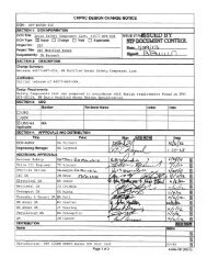
Note:<br />
Premier Technology, Inc.<br />
Factory Acceptance Test <strong>Report</strong><br />
242-A Evaporator HVAC K1 Exhaust Ventilation System Upgrade<br />
RPP-RPT-49670 <strong>Rev</strong> 0<br />
Factory Acceptance Testing (<strong>FAT</strong>) was initiated by Premier Technology, Inc. (Premier) using revision 5 of<br />
the Factory Acceptance Plan which had been approved with comments by Washington River Protection<br />
Solutions (WRPS) authorizing Premier to proceed with specific sections of the <strong>FAT</strong>. As such, certain<br />
sections of the <strong>FAT</strong> were signed off using revision 5 of the <strong>FAT</strong> Plan. These sections can be found in<br />
Attachment B of this report.<br />
Premier revised the <strong>FAT</strong> Plan and submitted rev 6 which addressed the majority of the outstanding<br />
WRPS comments, however not all of them, such that WRPS approved rev 6 of the <strong>FAT</strong> Plan with<br />
comments and authorized Premier to proceed with additional sections of the <strong>FAT</strong>. As such, certain<br />
sections of the <strong>FAT</strong> were signed off using revision 6 of the <strong>FAT</strong> Plan. These sections can be found in<br />
Attachment A of this report.<br />
Lastly, Premier again revised the <strong>FAT</strong> Plan and submitted rev 7 which fully and satisfactorily<br />
incorporated all outstanding WRPS comments such that WRPS approved rev 7 of the <strong>FAT</strong> Plan and fully<br />
authorized Premier to proceed with all remaining sections of the <strong>FAT</strong>. It is this revision that makes up<br />
the main body of this report and the appropriate references to either revision 5 or 6 in attachments B or<br />
A, respectively, are made therein.
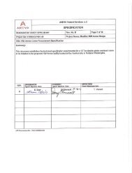
A Premiar T'echnaowg, ISC.<br />
1 858 W, Bridge Streest<br />
BlackfOotZD, 83221<br />
(208) 785-2274<br />
www.ptius.niet<br />
Washington River Protection Solutions 242-A Evaporator K1<br />
Exhaust Ventilation Systems Factory Acceptance Test<br />
Approvals Nm:Signature: Date:<br />
Preparer<br />
Technical J<br />
~ - c1illi<br />
Quality Assurance ~A~<br />
<strong>Rev</strong>ision 7<br />
CONTROLLED
(~?IEMIE -P<br />
PRxEER TECHNOLOGY, INC. Project No. 006765.0.000<br />
-242-A Evaporato Ki Exhaust Contract 40167<br />
\~k~ ag e hno ; I c.V entilation S stem No.<br />
RPP-RPT-49670 <strong>Rev</strong> 0<br />
1FACTORY ACCEPTANCE TEST PLAN S p e No0. R.PSev 0 06<br />
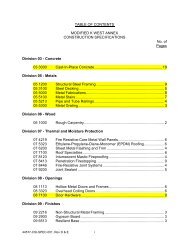
Table of Contents<br />
1.Purpose and Scope;............................................. ....... ..........<br />
1. pups .......................................<br />
. .........................<br />
~.......................... ...............<br />
1 oiscope e............................... ......................<br />
1.5 ..............................................<br />
1. efernScoe .......................... ......... ...... ...... ........ ...........<br />
IA. IformtIo.....................................................................---.... -*...4*<br />
1 .1 Tef ras d.............iti<br />
.. n......................................4<br />
.....<br />
2. TstPesone........................... ........................ 6<br />
2.4<br />
2.1<br />
Genelitu.........................................................<br />
Tes Exde ntions .................. : . ............................... I.................... . . . . . 7<br />
.6 rmRso A e. . . ... .................................<br />
........................................... 7<br />
* 2.71 Syise ..... I................................................<br />
2.8 an RCUD~S uspnsiD Tst.................................<br />
o Tet<br />
2.9 TesPeonneihl .............. ........................................<br />
8<br />
.4 Preuinend info ations..................................................................<br />
3.1 Prsonel sfety.............................. ..................... 9<br />
.2<br />
.6<br />
es Eipen ........................................................<br />
Aar m es pons... ........................................................................................<br />
.<br />
1<br />
.1<br />
4.1.Test.Spe..fic.p....o........i................................<br />
I..................1 7<br />
.2 Spsei1 Stools, Equ...pment........d..Suppli............ .. . . . . . . ............ ........<br />
.8 Susensionof.T.t..n..........et......................... ..............<br />
6.9 TesnusidelifFA............................<br />
6. ~.................<br />
...........................<br />
...................<br />
1<br />
.2 Vaers/Da-aper -................. Te.........*... ...................... 3<br />
6.3 Pessure.rop........................ Damers -<br />
....................... 14<br />
4.2 entandSi~ pecal ools, lies....................................<br />
E uip<br />
6.4 DanpersSeat&.........C<br />
Sch du v ....<br />
:...................................................................A..<br />
1. Pemn O ide e ology,..........................<br />
.....
PREMIER TECHNOLOGY, INC. 1'rojectNo. 006765.0.000<br />
VWS - 242-A Evaporator KI Exhaust Contract 40167<br />
Ventilation System<br />
No.<br />
FACTORY ACCEPTANCE TEST PLAN Spec No. Re 0<br />
RPP-RPT-49670 <strong>Rev</strong> 0<br />
6.5 FilterTran -PessureBoundaryLekage ........................I.....I<br />
....................................... 17<br />
6.6 Instrumentation and power wiring - Continuity and megger testing.........................................is<br />
6.7 Pre-Filter Diffetial Pressure indicators - Verify Differential Pressure Indicator Function............. 19<br />
6.8 Local I' Stage BEPA Section Pressure Indicators - Verify Differential Pressure Indicator Function ... 20<br />
-6.10<br />
6.9 Loal "~Stge EP Sctin resure idcatr- Verify Differential Pressure Indicator Function ... 21<br />
Exhaust Stack <strong>Sample</strong> Pitot Tube and Transport Lines - Leak test & Pitot Tube Alignment............. 22<br />
6.11 Mass Flow Controller Record <strong>Sample</strong>r and Vacuum Pump .................................................. 22<br />
6.12 Mass Flow Controller CAM and Vacuum Pump ......... ... I...............................................2<br />
6.13 Vacum Pump -Verify Purmp operation .......................................................... ......... 24<br />
6.14 Continuous Air Monitoring -Verify CAM Alarm and Interlock Set point .......~........I...............24<br />
6.15 <strong>Sample</strong>r line Vacuum. Indicator - Functional Test (P1-1)................................................... 25<br />
6.16 <strong>Sample</strong>r Line Vacuum Indicator -Functional Test (P1.1l-2)...........I....................................... 25<br />
6.17 CAM Operation - Verify'No Electromagnetic Radation Interference ............ ......................... 25<br />
6.18 Sampling system instrumentation and wiring - Continuity and megger testing............................. 25<br />
6.19 <strong>Sample</strong> Cabinet cooling fan -Functional test ................................................................. 26<br />
620 Verabar Flow Sensor - Verify Exhiauster Flow Indication ................................................... 26-<br />
6.21 Sampling Manifold - Qualification of Filter Sampling System .............................................. 27<br />
6.22 Fan and Motor .- Vibration (Drive motor rotating elements) & Sound ...................................... 28<br />
6.23 Intake Plemn & Expansion Joints - Pressure, Decay Test & Bubble Leak Test............................<br />
7 Procedure..........................................................<br />
.....................................<br />
29<br />
29<br />
7.1 Valves/Dampers - Visual inspections ............... t........................ ................................ 29<br />
7.2 Valve/Dampers - Verify Isolation Valve Position Indication and Function................................. 31<br />
7.3 Filter Train - Visual Inspection ........ 7 . ............ I......................................................... 33<br />
7.4 242-4 Evaporator KI Exhaust - Pressure Decay Test & Bubble Leak Test................................. 35<br />
7.5 Power Instriuent and Control Cabling -Proper voltage and phase sequence at equipment served....39<br />
7.6 Dampers - Damper Cycle Time and Operation ................................. I..................... ......... 40<br />
7.7 KI-S2M Motor and VFD - Proper voltage at equipment served .................................. . ........ 1.42<br />
7.8 KI-5-2 Fan and Motor -Vibration Test (Minimum System Loss)........................................... 46<br />
7.9 Kl-5-2 Fan and Motor - Sound Test...........................................................................<br />
7.0 Section 1 Valves/Dampers - System Pressure Boundary Leak Test......................................... 50<br />
7.1 1( -5-2 Fan and Motor - Vibration Test (Maximum System Loss) .......................................... 51<br />
7.12 K1-5-3M Motor and VFD - Proper voltage at equipment served ............................................ 53<br />
2 Premier Technology, Inc.<br />
006765.0.OOO-<strong>FAT</strong>-OO1-1 (<strong>Rev</strong> 7)<br />
49
PREMIER TECHNOLOGY, INC. Project No. 006765.0.000<br />
[U WEpS - 242-A Evaporator KI Exhaust Contract 40167<br />
\~wv'Thhfll~g4 ~Ventlation System No.<br />
& Te~clno 09y Inc.PPC-36062<br />
FACTORY ACCEPTANCE TEST PLAN Spec No. <strong>Rev</strong> 0<br />
RPP-RPT-49670 <strong>Rev</strong> 0<br />
7.13 KI1-5-3 Fan and Motor - Vibration Test (Minimum System Lass).......................................... 57<br />
6<br />
7.14 Kl1-5-3 Fan and Motor - Sound Tog..................I......................................................<br />
7.15 Section 2 Valves/Dampers - System Pressure Boundary Leak Test.....*................................... 61<br />
7.16 Stack Joint -Bubble leak est....................................................<br />
............................ 62<br />
7.17 KI-5-3 Fan and Motor - Vibration Test (Maximum System Loss)......................................... 63 L<br />
7.18<br />
7.19<br />
Filter Train A - Airflow Distribution (Full System).........................................................64A<br />
Filter Train B - Airflow Distibution (Full System)-...I...........I...................................<br />
...... 66<br />
7.20<br />
7.21<br />
7.22<br />
7.23<br />
Filter Train C -Airflow Distribution (Full Systemf)........................................................6<br />
Stack Sampling location -Angular or Cyclonic flow ......................................................<br />
6<br />
Stack Sampling Location - Contaminant Concentration and Velocity Profiles .........................<br />
.. 71<br />
Exhaust Stack Sarle; Line - Heat Trace Thermostat for CAM airborne Radiation Detector (GS)I....73<br />
8. -Completion of<strong>FAT</strong> Test.............'.........1 ...........- ..................... I..................1<br />
9. Attachment List.................... ............................................................................<br />
1. Purpose and Scope<br />
1.1 purpose<br />
This pro cedure was created for the purpose of performing Factory Acceptance Testing<br />
(<strong>FAT</strong>) of the 242-A Evaporator K1 Exhaust ventilation System provided by Premier<br />
Technology, Inc. for Washington River Protection Solutions (WRJ'S).<br />
The objective of this document is to provide a description of the processes that will be<br />
followed at the manufacturer's facility in order to performi t Factory Acceptance Testing<br />
of the 242-A Evaporator KI Exhaust Ventilation System in order to verify that the unit<br />
comp lies with the requirements of WRPS Specification RPP-SPEC-3 6062, <strong>Rev</strong>. 0 and the<br />
applicable flow down Specifications listed tberem".<br />
) 5M P49WD FA<br />
This Procedure will address all applicable components supplied by this order. These<br />
components are listed i section 6 and 7 of this <strong>FAT</strong> test The findings of each test shall be<br />
recorded in separate section of this document for each component.<br />
The testing will be performed at Premier Technology's facility.<br />
3 Premier Technology, Inc.<br />
fM -M&(hSAP ~ (7r. ~<br />
I 7 7L~ --<br />
OO6765.O.00-<strong>FAT</strong>-O01-1<br />
84<br />
(<strong>Rev</strong> 7)
(i ET<br />
RPP-RPT-49670 <strong>Rev</strong> 0<br />
MIERT<br />
PREMIER TECHNOLOGY, INC.<br />
W.RPS - 242-A Evaporator KI Exhaust<br />
Project No.<br />
Contract<br />
006765.0.000<br />
40167<br />
'Fehooy n.Ventilation System No.<br />
FACTORY ACCEPTANCE TEST PLAN ISpec No. IPPSev -300<br />
7.24 Continuous Air Monitoring - Verify CAM bypass feature .................................................. 74<br />
7.25 Vacuum Pump - Verify Pump operation...................................................................... 76<br />
7.26 C AM Operation - Verify No Electromagnetic Radiation Interference ...................................... 77<br />
7.27 <strong>Sample</strong> Cabinet cooling fan - Functional test ....................... ......................................... 78<br />
7.28 Inlet Plenum & Expansion Joints - Pressure Decay Test & Bubble Leak Test ............................. 79<br />
7.29 Exhaust Stack <strong>Sample</strong> Pitot Tube and Transport Lines - Leak test & Pitot Tube Alignment............. 81<br />
7.30 <strong>Sample</strong>r line Vacuum Indicator - Functional Test (PI1) .................................................... 82<br />
3a Premier Technology, Inc. 006765.O.OOO-<strong>FAT</strong>-0O1-1 (<strong>Rev</strong> 7)
PREMIER TECHNOLOGY, INC. ProjectNo. 006765.0.000<br />
ER WRS 242-A Evaporator Ki Exhaust conwmct<br />
p"DEM<br />
(Z -Tlchnowg Inc. Ventilation Systm No. 40167<br />
1.2 Scope<br />
RPP-RPT-49670 <strong>Rev</strong> 0<br />
FACTORY ACCEPTANCE TEST PLAN Spec No RPPSPEC-36062<br />
<strong>Rev</strong> 0<br />
This procedure is to demonstrate that the 242-A Evaporator KI Exhaust Ventilation System<br />
preforms properly in accordance with the WRPS Specification RPP-SPEC-36062, <strong>Rev</strong>. 0,<br />
NEMA MG-i 2007, ASME AG-I, TFC-ENG-STD-07, and ANSIN13.1.<br />
1.3 Not in Scope<br />
"None"<br />
1.4 Assumptions<br />
Test configuration matches onsite conditions 'with the following exceptions:<br />
* Temporary wiring will be used between major components. (Permanent wire will be<br />
provided new and unused)<br />
* Facility Differential pressure will be simulated by throttling filter housing inlet.<br />
butterfly valves.<br />
6 VCS and MCS are not available, communication will be verified by continuity<br />
checks<br />
0 Temporary power will be used in place. of facility power.<br />
These assumptions have no impact on execution or results of the <strong>FAT</strong>.<br />
1.5 References<br />
1.5.1 -ASHR.AIE 52 2007<br />
1.5.2 IMEE 112 2004<br />
1.5.3 AMCA 500 1989<br />
1.5.4 ANSI N13.1 1999<br />
1.5.5 ASMEfiB31-1 2007<br />
1.5.6 AMCA 2041996<br />
1.5.7 ASME AG-i 2003<br />
1.5.8 40OCFR 60<br />
2. Information<br />
2.1 Terms and Definitions<br />
2.1.1 <strong>FAT</strong> Factory Acceptance Test<br />
4 Premier Technology, Inc. 006765.0.000-<strong>FAT</strong>-001-1 (<strong>Rev</strong> 7)
PREMIER TECHNOLOGY, INC. Project No. 00616&.0.000<br />
WRPS - 242-A Evaporator Ki Exhaust Contract 40167<br />
eMhoo~~Inc. Ventilation System<br />
FACTORY ACCEPTANCIE TMS PLAN Spec No. 0<br />
RPP-RPT-49670 <strong>Rev</strong> 0<br />
2.1.2. RPS Washington River Protection Solutions<br />
2.1.3 QA Quality Assurance<br />
2.1.4 NQA Nuclear Quality Assurance<br />
2.1.5 ASMB American Society Of Mechanical Engineers<br />
2.1.6 AMC Air Monitoring Corporation<br />
2.1.7 PPE personal Protective Equipment<br />
2.1.8 OAT operational acceptance test<br />
2.1.9 VCS Ventilation Control System<br />
2.1.10 SCF Standard Cubic Feet<br />
2.1.11 CAM Continuous Air Monitor<br />
2A1.12 VFD Variable Frequency'Drive<br />
2.1.13 SWC Snall Logic.Controller<br />
2.1.14 )MM, DigitalMultimeter<br />
2.1.15 P1)11 Pressure Differenitial1 Indicating Transmitter<br />
2.1.6 PID '"Proportional Integral Derivative<br />
2.1.17 H~MI. Human Machine Intrface<br />
2.1.18 PLC Programmable Logio Controller<br />
2.1.19 BUMP To briefly energize<br />
2.1.20 M&TE Measurment and Testing Equipment<br />
2.1.21 MCS Monitoring control. system<br />
2.1.22 AWG America Wire Gauge<br />
2.1.23 CAT Construction Acceptance Test<br />
2.1.24 ENSUR Confirm that an activity or condition has occurred in conformance with<br />
specified requirements, and take action to make it so if the condition is<br />
NOT found to be in conformanc-e.<br />
2.1.25 VERIFY Perfor-m a comparison with stated requirements. No manipulation of<br />
equipment of other subsequent actions by the checker are involved.<br />
Verifications normally require initials or signature.<br />
2.1.26 STEADY STATE OPERATION<br />
Fan running at equilibrium at a set flow rate and system warmed up.<br />
2.2 units<br />
2.2.1 % Percent<br />
2.2.2 F Fahrenheit<br />
2.2.3 Hp Horsepower<br />
2.2.4 A Amps<br />
5 Premier Technology, Inc.<br />
006765.O.OOO-<strong>FAT</strong>-OO1-1 (<strong>Rev</strong> 7)
PREMIER TECHNOLOGY, INC. Project ~q 0 006765.0.000<br />
WRPS - 242-A Evaporator K1 Exhaust Contract 40167<br />
RPP-RPT-49670 <strong>Rev</strong> 0<br />
(E~EMIERNo<br />
Tecnkg Ventilation System N.~ ~ C66<br />
Tecnoogy Ic- FACTORY ACCEPTANCE TEST PLAN SpecNo. RP-SEC366<br />
2.2.5 VAC Volts Alternating Current<br />
2.2.6 dBA decibels (weighted on 'A' scale)<br />
2.2.7 psi Pounds per square inch<br />
2.2.8 in inch<br />
2.2.9 mm millimeter<br />
2.2.10 in Hg Inches of mercury<br />
2-2.11 AWG American Wire Gage<br />
2.2.12 IN~ W.G. Inches Water Gauge<br />
2.2.13 IN W.C. Inches Water Column<br />
2.2.14 SCFM Standard Cubic Feet per Minute<br />
2.2.15 rpm revolutions per minute<br />
2.3 Test Personnel<br />
The Following personnel are required to conduct the Factory Acceptance Testingfte22<br />
A Evaporator Ki Exhaust Ventilation SystemA<br />
2.3.1 Test Director<br />
The test director will be present for all testing. This individual will be the Project<br />
Manager for the project unless otherwise designated.<br />
2.3.2 Test Technicians<br />
Test Technicians will assist the Test Director in the preparation of hardware and<br />
equipment for the <strong>FAT</strong> tests. These individuals will be familiar with the equipment.<br />
being used.<br />
2.3.3 QA Personnel<br />
Quality Assurance personnel will be present for all listed functions of the testing. The<br />
QA designee will record the results and test data of the testing.<br />
2.4 General Information<br />
2.4.1 Editorial changes may be made to thids procedure as required to accommodate<br />
procedural/editorial deficiencies that do not affect technical content Redline changes<br />
shall be entered using red ik, initialed and dated by the Test Director.<br />
2.4.2 Testing performed in the fabrication shop shall comply with shop Lock and Tag<br />
policy requirements. Fabricator shall verify general requirements, roles, and<br />
responsibilities.<br />
*6 Premier Technology, In c. 006765.0.000-<strong>FAT</strong>-0O1-1 (<strong>Rev</strong> 7)
PREMIR TECHNOLOGY, INC. Project No. 006765.0.000<br />
(~ T f R WRPS - 242-A Eaporator KI Exhaust contract 406<br />
\&/olo yI±E Ventilation SEste<br />
FACTORY ACCEPTANCE, TEST PLAN spec No. RPPSev-3<br />
RPP-RPT-49670 <strong>Rev</strong> 0<br />
2 .4.3 Verifiation of each test shall be documented at the end of each test section by having<br />
the Test Director and the QA Personnel Sign and date the test section.<br />
2.5 Test Exceptions<br />
2.5.1 Test exceptions are used to document unexpected tes euttcnclpoeua<br />
deficiencies, and identify appropriate action.<br />
2.5.2 A description and a resolution for the test exceptions shall be documented in<br />
Attachment 1 <strong>FAT</strong>, Test Exception Record<br />
2.5.3 In the event of an equipment malfunction or other anomaly, the Test Director shall<br />
document the condition with a&Test Exception Record and assess the effect on<br />
equipment and direct either<br />
* Continuation of the test in. the same section.<br />
*proceeding to another attachrmbnt or section of the test.<br />
* Suspensibn of the test nd tstablishnidtit of a safe condition for equipment<br />
(See Section I!).<br />
2.5.4 Test exceptions and discrepancires that cannot be orreted in- accordance with this<br />
procedure will he documented and addressed on a non-conformnce report, per<br />
Premier Technology, Inc. NQA-l Quality Assurance Program.<br />
2.6 Alarm Response<br />
2.6.1 This procedure identifies all alarms expected as a result of testing, and provides<br />
instructions for responding to those alarms, During testing of Hfigh or Low set points,<br />
High and Low alams are also anticipated.<br />
2.6.2 Unexpected alarms received during testing shall be logged as test exceptions in<br />
Attachment 2, Test Exception Log and evaluated by the Test Director for effect on<br />
the test.<br />
2.6.3 All test exceptions, must be recorded in Attachment 2, <strong>FAT</strong> Test Exception Log,' and<br />
explained in detail in the Attachment 1, <strong>FAT</strong> Test Exception Record.<br />
2.6.4 Variation between EIM alarm terminology and alarm terminology provided in this<br />
<strong>FAT</strong> is not cause to stop testing. The variance shall be evaluated by the Test Director<br />
to confirm desired system response and documented on Attachment 3, <strong>FAT</strong> Test Log.<br />
2.7 System-Status<br />
2.7.1 Record all abnormalities in equipment configuration, comments, observations by<br />
participants, and all other data pertinent to the test in the Attachment 3 <strong>FAT</strong> Test<br />
7 Premier Technology, Inc.<br />
006765.O.OO-<strong>FAT</strong>OO01-1 (Rtev 7)
PREMIER TECHNOLOGY, INC. Project No. 006765.0.000<br />
(P~ IE AI~ R WRPS - 242-A Evaporator K1 Exhaust Contract 40167<br />
RPP-RPT-49670 <strong>Rev</strong> 0<br />
' Teho gyi.Ventilation System .No. RI-PC30<br />
FACTORY ACCEPTANCE TEST PLAN Spec No. RuPSev 0 06<br />
Log. If applicable, initiate a test exception by identifying the condition in the<br />
Attachment 2, <strong>FAT</strong> Test Exception Log.<br />
27.8 Suspension of Test and Resuming Test<br />
2.8.1 The Test Director may, at his discretion, stop testing and place equipment in a safe<br />
condition. All suspension of testing due to exceptions shall be documented in the<br />
Attachmnent 3, <strong>FAT</strong> Test Log.<br />
2.8.2 If a section of the test is suspended for any reason prior to completing all steps, the<br />
Test Director shall establish initial conditions necessary to resume testing for that<br />
section. Previously completed sections need not be repeated unless directed by the<br />
Test Director to establish conditions required to resume the test.<br />
2.8.3 WEPS is to be advised of the condition(s) that resulted in the suspension of any test<br />
along with the expectd resplution. Prior to resuming any terminated test WR.PS is to<br />
be notified.<br />
2.8.4 Sections of this procedure may be performed out of sequence as lon g as components<br />
or-tests are NOT altered. Steps within ech section must be performed in order except<br />
section 7.1 which is pre-.requisite to 7.2 and 7.3 which is a pre-requisite to 7.4 and as<br />
indicated in sections 7.8-7.11, 7.13-7.17, and 7.18-7.22. these tests must be<br />
performed in order.<br />
2.9 Responsibilities<br />
2.9.lIThe Test Directr shall-<br />
8 Premier Technology, Inc.<br />
* .Verify prerequisites are completed prior to start of testing.<br />
*Maintain control of the testing process and change record authorization for<br />
this procedure.<br />
a Ensure all required data is collected.<br />
* Ensure safe working conditions and practices.<br />
'Ensure compliance with test documents.<br />
*Ensure review and approval of all modifications to test procedures are<br />
* complete prior to return to testing.<br />
*Act as direct line of communication and centralized point of control during<br />
normal, abnormal, and casualty situations.<br />
*Conduct pre-test briefings as required.<br />
* Schedule and reschedule tests as required.<br />
*Conduct pre-test system walk-downs.<br />
*<strong>Rev</strong>iew test documents to validate acceptance.<br />
006765.O.OO-<strong>FAT</strong>-OOI-l (<strong>Rev</strong> 7)
P MR TECHNOLOGY, INC. Project No. 006765.0.000<br />
WRPS - 242-A, Evaporator Ki Exhaust Contract 40167<br />
RPP-RPT-49670 <strong>Rev</strong> 0<br />
(~T~CI11OOg)~X1C entilation SYStem No<br />
FACTORY ACCEPTANCE TEST PLAN Spec NO. <strong>Rev</strong>.PR-306<br />
*Record equipment statuis and data in accordance with this procedure.<br />
*<strong>Rev</strong>iew, approve and record data exceptions and their resolutions and other<br />
*notes as required on the applicable attachinents.<br />
*Prepare post-testing documents<br />
*verify component ID is correct for the component being tested.<br />
* verify comnpletion. of each test section.<br />
& Verify proper valve andAlectrical alignment before each test section.<br />
* Provide technical support during testing.<br />
a <strong>Rev</strong>iew test documents to validate acceptance.<br />
* verif current version of software.<br />
0 Sign verification of data on calculation attachments.<br />
. <strong>Rev</strong>iew-recorded data for completeness -and accuracy.<br />
<strong>Rev</strong>iew and approve test exoepiQ~s. and tl~eir resolutions.<br />
*<strong>Rev</strong>iew <strong>FAT</strong> for compltenss w' acqI;1OQW Y.<br />
2.9.2 QA Personnel shall:<br />
* Verify component ID is correct for thecomponent being tested.<br />
* <strong>Rev</strong>iew procedure for accuracy and comnpleteness.<br />
. <strong>Rev</strong>iew the PAT for accuracy and completeness.<br />
* <strong>Rev</strong>iew and approve test exceptions and their resolutions.<br />
2.9.3 The Quality Control Inspector shall:<br />
a Witness testing.<br />
* <strong>Rev</strong>iew recorded data for accuracy and completeness.<br />
-- Verify completion of each test section.<br />
*Verify completion of test exceptions and their resolutions.<br />
2.9.4 Test Technicians shall:<br />
0 Provide assistance during testing.<br />
* provide equipment for performance of this procedure.<br />
3I Precautions and Limitations<br />
3.1 Personnel Safety<br />
All persons within the test area shall wear the appropriate Personal Protective Equipment<br />
(PPE). At a minimum this shall include eye protection. Gloves should be worn where there<br />
is a likelihood of contactig sharp edges or when handling rigging equipment.<br />
9 Premier Technology, Inc.<br />
006765.O.OWO<strong>FAT</strong>-OO1-l (<strong>Rev</strong> 7)
PREMIER TECHlNOLOGY, INC. Project No. 006766.0.000<br />
RPP-RPT-49670 <strong>Rev</strong> 0<br />
(~1 NA ER WRS - 242-A Evaporator Ki Exhaust Contract 40167<br />
TcnlgInc. Ventilation System No.<br />
FACTORY ACCEPTANCE TEST PLAN Spec N~o. RPPeC-306<br />
All persons within the test area are authorized to immediately halt testing should they<br />
observe an unsafe condition that could compromise the safety of themselves, other persons<br />
in the test area or the safety of the equipment Concerns should be addressed to the test<br />
director to ensure an orderly and controlled shutdown of the equipment being tested.<br />
NOTE: Energized circuits and leads are contained inside cabinets, Failure to comply with<br />
appropriate electrical PPE and safety procedures can cause serious personnel injury or death<br />
from electrocution.<br />
3.2 Equipment Safety<br />
3.2.1 A pre-test briefing should be conducted to identify unusual and for hazardous<br />
conditions<br />
3.2.2 Shop'safety rules should be stzictly adhered to during the performance of ths test<br />
3.2.3 Shop Lack and Tag requirements should be followed at all times during the<br />
performance of this test<br />
4. Prerequisites<br />
4.1 Test Specific pre-configurations<br />
4.1.1 Any settings, configurations, etc, which are required for specific tests (prior.to<br />
beginning the numbered test steps) shall be determined by the test director, who shall<br />
direct personnel to make any necessary configuration changes. Prerequisites listed.<br />
elsewhere in this test procedure but not required for a particular test do not have to be<br />
performed, at the discretion of the test director. This includes ensuring that all gaskets<br />
have been installed, holes have been sealed, and any valves have been properly positioned.<br />
4.1.2 Ensure that all apparatus on the 242-A Evaporator KI Exhaust Ventilation Systemn<br />
necessary for the performance of the Test Procedure have been installed and are fully<br />
operational. This includes ensuring that all gaskets have been installed, holes have<br />
been sealed and any valves have been properly positioned.<br />
4. 1.3 Ensure that the equipment to be tested is free of dirt, chips, scale or any other debris<br />
that would hinder testing. Cutting fluids and residual oils shall be removed from the<br />
surfaces of the housing and components.<br />
10 Premier Technology, Inc. 006765.O.00-<strong>FAT</strong>-0O1-1 (<strong>Rev</strong> 7)
I 6.1<br />
RPP-RPT-49670 <strong>Rev</strong> 0<br />
P E M T E C N O L G Y , I N C<br />
WRpS<br />
.<br />
- 242'-,A Evaporator Ki Exhaust Contract J' N 40167 0 7 . . 0<br />
Ventlation 'RstemnNo<br />
& echnology, Inc. P P. M-VC362<br />
FACTORY ACCwzTANCE TEST I LAN SWe N& Rv,<br />
PP LEMIER<br />
4.1.4 Test Procedure <strong>Rev</strong>iew - The test director shaI enure that all Persons participating<br />
in testing as Test Technicians have reviewed and understood the requirements Of the<br />
test procedure and the equipment to be tested.<br />
4.1.5 The signature in Testing Outside of <strong>FAT</strong> serves as confirmation by Premier<br />
indicating that the subject documentation was reviewed, verified, complete, and<br />
accepted.<br />
4.2 Special Tools, Equipmentand Sutpplies<br />
& Compressed air source (0.25 00)<br />
9 covers to seal te~t boundaries<br />
* clock or tinmer capable of reading seconds,<br />
apressuro-indicatg device accurate to t 0.1 in:.wg [02(25 kPA (gage)]*<br />
*flow meter or totalizing gas volume meter accurate to 15%/ (conant-presSure<br />
method)*<br />
*temperafure-indicaiof device accurate to 6-05TF (0.25*C)o<br />
*bubble solution for detecting air leaks (bubble method)<br />
* optional portable electronic sound detection equipment (audible leak method)*<br />
" barometer*<br />
" Amp Meter*<br />
" Volt Metr*<br />
NOTE: *Calibration information required,<br />
5. Schedule<br />
The schedule is.deennned by the test director according to scheduling of subcontractors<br />
and pre-requisites to each specific test listed in section 7.<br />
6,. Testing Outside of <strong>FAT</strong><br />
Testing that was accomplished or will be accomplished by vendors, contractors, and<br />
standard NQA-I manufacturing practices that can be used to validate any <strong>FAT</strong> are verified<br />
in this section.<br />
Electric D~rive Motor - Motor RuD Test<br />
MAT=I REFERENCE - line 1, 2, & 3<br />
11 Premier Technology, Inc.<br />
006765.O.000-<strong>FAT</strong>-0O1-1 (<strong>Rev</strong> 7)
PRELMIER. TECHNOLOGY, INC. Project No. 006765.0.000<br />
(UP E M4IER WRPS - 242-A Evaporator KI Exhaust Contract 40167<br />
\ 4~cn~oy ic Ventilation System No.<br />
Techollgy, nc.RPP-SPEC-36062<br />
FACTORY ACCEPTANCE, TEST PLAN Spec No. <strong>Rev</strong> 0<br />
RPP-RPT-49670 <strong>Rev</strong> 0<br />
BACKGROUND - This test is to show that electric drive motors are in accordance with<br />
IEEE standard 112.<br />
COMPONENT BEING TESTED:<br />
* Kl-5-2-M<br />
* KI-5-3-M<br />
ACCEPTANCE CRITERIA:<br />
0 Motor is free of mechanical and electrical defects and is within mnanufacturers<br />
tolerance<br />
* Efficiency shall equal or exceed 94.1%<br />
* Locked motor current shall not exceed 543 A for 75 Hp motor at 460 VAC<br />
* Motor is certified to NEMA MG-1<br />
TEST PROCEDURE:<br />
6.1.1 RECORD motor efficiency from motor nameplate.<br />
6.1.2 RECORD motor locked rotor amps form motor nameplate.<br />
6.1.3 REVIEW manufacturer's certification documents in Attachment 6.1 (see Baldor<br />
Reliance Product Information Packet ECP843 16T-4 page 8 of 8 & Baldor<br />
Petroleum/Chemical Solutions Cataloged page 5 841XL Motor).4k<br />
Motr*.<br />
IKs-5-24W<br />
Nameplt Certification<br />
Effciecy ockd aps<br />
Efdcy LdamsEfficiency Locked amp'sIs<br />
95A 542 SA4Z-<br />
Intals<br />
Test IQA<br />
Director I nsixotor<br />
KI-5-3-M 954426<br />
6.1.4 CONFIRM the acceptance criteria have been met. I "<br />
6.1.5 Test Director VERIFY test is complete.<br />
Test Director Signature<br />
12 Premier Technology, Inc.<br />
D ate<br />
006765.04000-<strong>FAT</strong>-O01-1 (<strong>Rev</strong> 7)
PREMIER TECHNOLOGY, INC. Projectflo. 006765.0.000<br />
(P ZI M I R WRP - 242-A Evaporator Ki Exhaust Contract 40167 *<br />
N'v~I~echnolog~ inc Ventilation System_____nPSE-66<br />
FACTORY ACCEPTANCE TEST PLAN SpecNo. R" 0<br />
6.1.6. QA Inspector VERUFY test is complete.<br />
QA Inspector Signature<br />
6.2 Valies/Dampers - Shell Leak Test<br />
MATRI REFER~ENCE - line 16 & 17<br />
Date<br />
RPP-RPT-49670 <strong>Rev</strong> 0<br />
BACKGROUND - This test is to show that valves meeting the ASME B3 1.1 requirements<br />
have no visual detectable leaks.<br />
COMPONENT BEING TESTED:<br />
*KI-HV-001<br />
9 ,-3V02<br />
KI-HV-003<br />
*KI-HV-00<br />
*KI-HV-017<br />
K 1l-HV-024<br />
ACCEPTANCE CRITERIA:<br />
*Visually detectable leakage through the pressure boundary is not acceptable. The<br />
pressure boundary includes, along with the body, bonnet, or Cover, all gasketed<br />
joints; however, leakage through the stem seals or stem packing shall not be cause<br />
for rejection. Stem seals or stem packing exempted from the shell test pressure<br />
leakage requirement shall be capable of retaining pressure up to the 38 0 C (I100 0 F)<br />
pressure rat ing without visible leakage.<br />
*Ultra High molecular Weight Polyethylene (UIIM PE) seats shall be tested in<br />
accordance with API 598 hydrostatic high-pressure closure test at 110% of the<br />
design differential pressure at the 100*F rating<br />
TEST PROCZDURE:<br />
6.21 REVWW manufacturer's certification documents located in Attachment 6.2 (see<br />
ABZ Valves & Controls Summary & Manufacture drawing 30" 402-205-Gear).<br />
6.2.2 -CONFIRM the acceptance criteria have been met by initialing data table.<br />
FIAT 6.2 ASME B31.1 Iiil<br />
13 Premier Technology, Inc.<br />
006765.0.000-<strong>FAT</strong>-OO1-1 (<strong>Rev</strong> 7)
PREMIER TECHNOLOGY, INC. Project No. 006765.0.000<br />
(i EM IER WRPS - 242-A Evaporator KI Exhaust Contract 40167<br />
\iw'Technology, '11c. Ventilation System No.<br />
RPP-RPT-49670 <strong>Rev</strong> 0<br />
FACTORY ACCEPTANCE TEST PLAN SpecNo. RPP.SPEC-36062<br />
<strong>Rev</strong><br />
Valve List Satifed Unsatisied Test QA<br />
KCI-HV-001 K___________<br />
ICI-HV-002 3<br />
K-IIV-003<br />
KI-HV-010<br />
X<br />
11<br />
'f<br />
K1-HIV-024,y<br />
6.2.3 Test Director VERIFY test is complete.<br />
Test Director Signature Date<br />
6.2.4 QA Inspector VERIFY test is complete.<br />
QA Inspector Signature Date<br />
6.3 Dampers - Pressare Drop<br />
MATRIX REFERENCE - line 18<br />
BACKGROUND - ASME AG-i, DA-51 10 Pressure drop data shall be based on tests<br />
performed in accordance with AMQA Standard 500. The AMCA Standard number used<br />
shall be stated with the pressure drop data.,<br />
COMPONENT BEING TESTED:<br />
* Kl-MOV-001<br />
* KI-MOV-002<br />
0 KI-BDD-001<br />
* Kl-BDD-002<br />
e K1-)DMPR-001<br />
0 Kl-DMPR-002<br />
K ACCEPTANCE CRITERIA - Pressure drop wil be within 10% of value used to size the<br />
fan. Test data or manufacturer certification on damper style is acceptable..<br />
-56u ie.-r Vrh'-'tI'. ;at AUIE?'QVu C -r 'FaJ'~<br />
TEST PROCEDURE:<br />
14 Premier Technology, Inc. 006765.0.000-<strong>FAT</strong>-001-1 (<strong>Rev</strong> 7)
PiEMIER TECHNOLOGY, INC. ProjectNo. 006165.0.0007<br />
WRIS - 242-A Evaporator Ki Exhaust Cotr 40167<br />
\~ t mhooy n. -Ventilation System No.SEC366<br />
FACTORY ACCEPTANCE TEST PLAN Spec No. <strong>Rev</strong> 0<br />
RPP-RPT-49670 <strong>Rev</strong> 0<br />
6.3.1 REvIEw manufacturer's certification documents located in Attachment 6.3 (see<br />
Quality verification Documentation page 3 and pressure drop chart) and fan sizing<br />
calculation.<br />
6.3.2 CONFIRM the acceptance criterion has bee met by initialing dataL table.<br />
<strong>FAT</strong> 6.3 ASME AG-1, DA-5110 Initials<br />
Test QA<br />
Damper list Satisfied Tisfed 7 kpao<br />
KI-MOV-001 IZ<br />
KI-MOV-001 Fk ' II ..<br />
KI-BDD-002 JL_ __ _ __ _<br />
KI-DNM-401 y C f<br />
R1.DhM-002 y- M h<br />
6.3.3 Test Director VERIFY test is complete.<br />
Test Director Signature<br />
*6.3.4 QA lnspector VERIFY test is complete.<br />
QA Inspector Signature<br />
6.4 Dampers - Seat & Frame Leakage<br />
MATRIX REFEMENCE - line 20 & 21<br />
Date<br />
Date<br />
BACKGROUND - ASME AG-I, DA-5 130, Pressure plates shall be bolted to the inlet and<br />
outlet side of the damper. The chamber created shall be pressurized to the specified frame<br />
design pressure with the blades partially open. Testing industrial style dampers shall be in<br />
accordance with the bubble method. ASME AG-i, DA-5 140, Seat leakage testing shall be<br />
performed or verified after oycle time and cycle repetition testing and frame leakage testing.<br />
COMPONENT BEING TESTED:<br />
e KI-MOV-001<br />
* KI-MOV-002<br />
* Kl-BDD-0Ol**<br />
15 Premier Technology, Inc.<br />
006765.0.0O0-<strong>FAT</strong>-O01-1 (<strong>Rev</strong> 7)
RPP-RPT-49670 <strong>Rev</strong> 0<br />
PREMIER TECHNOLOGY, INC. Prject No. 006765.0.000<br />
EM ER WRPS -242-A Evaporator KI Exhaust Contract 40167<br />
(D<br />
VentilationSystem ___o. ______<br />
FACTORY ACCEPTANCE TEST PLAN Spec No. RPPSevO 60<br />
* Kl.BDD-002**<br />
* KI-DMPR-001<br />
*Kl-DMPR-002<br />
NOTE: "*Dampers that are only required to be cycle tested, frame bubble test will be<br />
conducted in 7. 10 and 7. 15 for customer information only.<br />
ACCEPTANCE CRITERIA:<br />
* The damper shall be bolted to a pressure chamber which is then pressurized to the<br />
specified blade design pressure. A bubble solution (a commercial test solution or a<br />
solution consisting of equal parts liquid detergent, glycerin, and water) shall be<br />
applied to the damper seat area to be tested. A few moments later, but before the<br />
soap solution can dry, check the wetted areas and mark places where bubbles are<br />
being generated. Unless otherwise specified, a leak indication is any bubble 1/6 in.<br />
(1.58 mmn) diameter that forms in I see, or a bubble 9/32 in. (7.14 mm) that forms in<br />
1 mmd. Movement of the blades and actuators and linkage shall be smooth and<br />
without hesitation, and limit switches operate in their intended position.<br />
* Meets Leakage Class IV (DA-I NOTE: (3) Leakage Class TV is for applications<br />
where leakage is of no consideration.)<br />
TEST PROCEDURE:<br />
6.4.1 REVIEW manufacturer's certification documents located in Attachment 6.4 (see test<br />
report for each damper).<br />
6.4.2 CONFIRM th acceptance criteria have been met by initialing data table.<br />
<strong>FAT</strong> 6.4 ASMI AG-i, DA-5130 initials<br />
Dampr atifiedUnstisiedTest<br />
Lst<br />
Damer istSatslcd nsaisfedDirector<br />
QA<br />
Instiector<br />
K1-MOV-001<br />
I-MOV-0O2 VI OrZi~<br />
KI-BDD-002~t2L<br />
______002 X_ _ _ _ _ I-If<br />
6.4.3 Test Director VERIFY test is complete.<br />
/ LJ~t<br />
Test Director Signature Date<br />
16 Premier Technology, Inc. 006765.O.OO-<strong>FAT</strong>-001-I (<strong>Rev</strong> 7)
pRE2!mlIR TECHNOLOGY, INC. Project No. 006766.0-000<br />
(1~'T AM ER WRPS - 242-A Evaporator K1 Exhatust Contract 4016<br />
EMitg Inc. Vetilationi Systeim<br />
& nc.RPP-SPEC-36062<br />
Tecrjoog,<br />
No.<br />
FACTORy ACCE&PTANCE TEST PLAN Spec No. Rei<br />
6.4.4 QA In 3 to 7 VERIFY test is complete.<br />
.6.5 Filter Train -pressure<br />
MAT=I RnwmuNC - line 40<br />
Boundary Leakage<br />
RPP-RPT-49670 <strong>Rev</strong> 0<br />
BACKGROUND - BHEPA jilter' element holding frames at each filter position shall be<br />
press=redecay leak tested in accordance with the requirement of ASME N5 10, Section 7<br />
The filter trains shagl be pressure decay leak tested before test pro-fi1ter and HEPA filters are<br />
installed. Tetsal ecnuted to meet the riquiremetits of, ASM N51 0, Scin6<br />
COMPONENTBEIG TESTED:<br />
e Filter TrainlA<br />
& Filter Train B<br />
* Filter Train C<br />
ACCE'PTANC]& CRITERZIA -The leak rate shall not exceed 0.1% of the housing volume<br />
per hour at the system leak test pressure as defined in ASME AG-1 for leakage Class I<br />
(Table SA-B-13 10)<br />
TEST PROCEDURE:<br />
6.5.j RVIEW xnanufactoreres certification documents located in Attachment 6.5 (see<br />
leak test report for each filter housing)-<br />
6.5.2 CONFIRM the accptance criterion has been Met by initialing data table.-<br />
<strong>FAT</strong> 6.5 AsmE N510 Initials<br />
Tod QA<br />
Filer rati istSaisfedUhsatisfied<br />
Filer rai stisedDiretor Lit<br />
1<br />
Filter Train A<br />
Filter Train B<br />
Filter Train C<br />
17 Premier Technology, Inc,<br />
006765..000<strong>FAT</strong>-001- (<strong>Rev</strong> 7)
RPP-RPT-49670 <strong>Rev</strong> 0<br />
PREMIER TECHNOLOGY, INC. ProjectNo. D06765.0.000*<br />
( KEMIN ER WRPS - 242-A Evaporator Kl Exhaust Crct~ 40167<br />
_ Tchnology Inc Ventilation System - NO.<br />
FACTORY ACCEPTANCE TEST PLAN Spec No. RPP-SPEC-3606Z<br />
<strong>Rev</strong> 0<br />
6.5.3 Test Director VERIFY test is complete.<br />
/ 1 -<br />
Test Director Signature Date<br />
6.5.4 QA Inspector VERIFY test is complete.<br />
QA Inspector Signature bate<br />
6.6 Instrumentation and power wiring - Continuity and megger testing<br />
MIATRIX REWEPXNCE - line 37<br />
BACKGROUND - This test is to show that all wiring is connected properly and meets<br />
industry standards.<br />
ACCEPTANCE CRITERIA -<br />
* Resistance shall be 5 1 ohm for continuity checks for wiring #14 AWG and larger<br />
and:S 3 ohms for wiring #16 AWG and smaller.<br />
* Resistance to ground shall be 50 mega ohm minimum. Conductors rated 2: 600 V<br />
used for services, feeders or branch circuits over 150 V to ground, Phase-to-Phase<br />
and Phase-to-Ground insulation resistance 200 mega ohms. (Voltage output of<br />
megger shall be 1000 V dc nominal).<br />
TEST PROCEDURE:<br />
6.6.1 VERIFY continuity using Exhauster Electrical Assembly Traveler Attachment C -<br />
Continuity (see Attachmient 6.6).<br />
6.6.2 CONFIRM the acceptance criteria have been met<br />
6.6.3 Test Director VERIFY test is complete.<br />
Test Director Signature Date<br />
6.6.4 QA Inspector VERIFY test is complete.<br />
QA Inspector Signature Date<br />
18 Premier Technology, Inc. 006765.0.000-<strong>FAT</strong>-0O1-1 (<strong>Rev</strong> 7)<br />
4
P EMIERINo<br />
RPP-RPT-49670 <strong>Rev</strong> 0<br />
PREAM TECHNOLOGY, INC. Prjc~.0675000 1<br />
WRPS - 242-A Evaporator K1 Exhaust Contract 40167<br />
Inc. Ventilation SstemN.<br />
FACTORY ACCEPTANCE TEST PLAN SPec No. RI<br />
6.7 Pre-Filter Differential Pressure indicators - Verify' Differential Pressure<br />
Indicator Function<br />
MATRIX R~FER~ENCE - line 28<br />
BACKGROUND - Differential pressure is displayed and corresponding 4-20 mA signal is<br />
provided for operating range of -I to 9 inH2O.<br />
COMPONENT BEING TESTED:<br />
*PD1T-Kl -3 06<br />
*PDIT?-Kl -309<br />
*PDrr-K1-312<br />
ACCEPTANCE CRITERIA -Local<br />
output are within -1 to 9 inH2O.<br />
TEST PROCEDURE:<br />
pressure indicationsi and corresponding 4 -20 mA<br />
6.7.1 VERIFY appropriate 4-20 mA using Ehauster Electrical Assembly Traveler<br />
Attachmnent b- Loop Check Table 1. (S69 -WA aMz',n ( .L--<br />
6.7.2 CONFIRM the acceptance criterion has been met.<br />
6.7.3 PD]T-Kl-:306 Test DiretorZ. QA Inspector<br />
6.7A PDIT-Kl-309 Test DiretorX_-N. QA IispectorLkl<br />
6.7.5 PDLT-K1 -3 12 Test DirectorL?2. QA InSpetor~ k<br />
6.7.6 Test Director VERIFY test is complete.<br />
___<br />
Li 1115I<br />
Tes;t irector Signature Date<br />
6.7.7 Q n tor VERIFY test is complete.<br />
QA Inspector Signature<br />
19 Premier Technology, Inc.<br />
Date<br />
006765.O.000-<strong>FAT</strong>-O01-1 (<strong>Rev</strong> 7)
RPP-RPT-49670 <strong>Rev</strong> 0<br />
PREMIER TECHNOLOGY, INC. Project No. 006765.0.000<br />
E I R WRPS - 242-A Evaporator KI Exhaust Coutract 40167<br />
'A ciooy nVentilation System No.<br />
RPP-SPEC-36062<br />
FACTORY ACCEPTANCE TEST PLAN Spec No. <strong>Rev</strong> 0<br />
6.8 Local I" Stage UEPA Section Pressure Indicators - Verify Differential<br />
Pressure Indicator Function<br />
MATRIX REFERENCE - line 30<br />
BACKGROUND - Differential Pressure is displayed and corresponding 4-20 mA signal is<br />
provided for operating range of -1 to 9 inH 2O.<br />
COMPONENT BEING TESTED:<br />
* PDIT-K1-307<br />
e PDIT-KI-310<br />
* PDrT-Kl-')13<br />
ACCEPTANCE CRITERIA - Local pressure indications and corresponding 4 -20 niA<br />
output are withini 4to 9 ioIHaO.<br />
TEST PROCEDURE:<br />
6.8.1 VERIFY appropriate 4-20 mA using Exhauster Electrical Assembly Traveler<br />
Attachment D - Loop Check Table 1 (see Attachment 6.7).<br />
6.8.2 CONFIRM the acceptance criterion has been met<br />
6.8.3 PDlT-Kl-')07. Test DirectorL ~ QA Inspeco<br />
6..4 PDT-l-10Tet<br />
irctr_& - QAInp c<br />
6 w. DTK 30Ts irco.~§ Q npco<br />
6.8.5 PDIT-Kl-313 Test Director..~. QA Inspector .lw...<br />
6.8.6 Test Director VERIFY test is complete.<br />
Test Director Signature Date<br />
6.8.7 QA Inspector VERIFY test is complete.<br />
QA Inspector Signature Date<br />
20 Premier Technology, Inc. 006765.0.000-<strong>FAT</strong>-O01-1 (<strong>Rev</strong> 7)
RPP-RPT-49670 <strong>Rev</strong> 0<br />
PREMIE TECHNOLOGY, INC. Project No. . 0066..0<br />
(~~1VIE~R WRPS - 242-A Evaporator Ki Exhaust Confrac 40167<br />
P~iTcnlg Rnc Ventilationl Stem NO.<br />
Rr?'.SPC36062<br />
FACTORY ACCEPTANCE MET PLAN LSpeeo. Re 0<br />
6.9 Local 2 nd Stage HEPA Section Pressure indicators - Verify Differential<br />
Pressure Indicator Function<br />
MATRIX REFERENCE - line 33<br />
BaACKGROUND - Diffrrential Pressure is displayed and corresponding 4-20 MA signal is<br />
provided for operating range of -1 to 9 mnH 2O.<br />
COMPONENT B3EING TESTED:<br />
" PDIT-KI -308<br />
" PDIT-Kl-311<br />
" PDIT-Kl-314<br />
ACC1PTANCE CRMPRA - Localpressue indications anid orrspoding4 -20 mX<br />
output are within -I to 9 inH 2O.<br />
TEST PROCEDURE:<br />
6.9.1 vsRIFY appropriate 4-20 mA using Exhauster Electrical AssemblY Traveler<br />
Attachment D - Loop Check Table I (see Attahment 6.7).<br />
6.9.2 CONF]IRM the acceptance criterion hats been met<br />
6.9.3 PDIT-Kl -308 Test Dietr~QA Inspector Ct:-<br />
6.9.4 PDIT-Kl-311 Test Direcorjn,. QA Inspetor.i G.<br />
6.9.5 PDIT-KI-314 Test Director_1L!%- QA Inspector<br />
6.9.6 Test Director VERIFY test is complete.<br />
Test Director Signature<br />
6.9.7 QA Inspector VERIFY test is complete.<br />
QA Inspector Signature<br />
21 Premier Technology, Inc.<br />
Date<br />
Date<br />
006765.0.000-<strong>FAT</strong>-O01-1 (<strong>Rev</strong> 7)
RPP-RPT-49670 <strong>Rev</strong> 0<br />
PREMIER TECHNOLOGY, INC. Project No. 006'765.,000<br />
( E XIER WRPS - 24 2 -A Evapora t or Kl Exhaust Contract 406<br />
FACTORY ACCEPTANCE TEST PLAN ISpec No. I feo<br />
6.1OE xbaust Stack <strong>Sample</strong> Pitot Tube and Transport Lines - Leak test & Pitot<br />
Tube Alignment<br />
MATRIX RIF'ERENCE - line 46<br />
BACKGROUND - The stack sampling system shall be inspected for leaks at the time of<br />
installation in accordance with ANSI N13. 1, Section 6.9. PIC 3 stack allows for inspection<br />
as satisfactory method. Isolate and pressurize sample line to 5 psi.<br />
COMPONENT BEING TESTED:<br />
aExhiaust Stack sample pitot tube and transport lines<br />
ACCEPTANCE CRITERIA - No leaks detected using bubble testing on joints.<br />
TEST PROCEDURE:<br />
6.10.1 REVIEW AMC Factory Acceptance test <strong>Report</strong> section 3.1 (e- *Tktt-6 .io<br />
6.10.2 CONFIRM the acceptance criterion has been met.<br />
6.10.3 Test Director VERITY test is complete.<br />
Test Director Signature Date<br />
6.10.4 QA hInsector VERIFY test is complete. 1<br />
QA Inspector Signature Date<br />
6.11 Mass Flow Controller, Record <strong>Sample</strong>r and Vacuum Pump<br />
MATRIX REFERENCE - line 47<br />
BACKGROUND - RPP-SPEC-3 6062, <strong>Rev</strong>. 0, Section 3.3.4.2, # 10; <strong>Sample</strong> Flow<br />
Instrumentation: Each of the sample loops, including the record sampler loop and the CAM.<br />
sample loop shall include a mass flow controller Hastings model HFC-3 03, or Buyer<br />
approved equal. The flow controller shall send a 4-20 mA signal to the 242-A VCS and<br />
receive a 4-20 mA flew setpoint signal from the 242-A VCS. The sample flow will be held<br />
constant to accommodate the requirements of the collector or analyzer.<br />
COMPONENTS LIST:<br />
*22 Premier Technology, Inc. 006765.0.000-<strong>FAT</strong>-0O1-1 (<strong>Rev</strong> 7)
*<br />
PREMIER TECHNOLOGY, INC. Project No. 0067 5.0.0OO<br />
(~ W1 LIIR WRJ'S - 242-A Evaporator Ki Exhaust Contrat 40167<br />
VeEiltion te No.<br />
RPP-RPT-49670 <strong>Rev</strong> 0<br />
C<br />
RPP.SFEC-36062<br />
FACTORY ACCEPTAJNCE TEST PLAN spee <strong>Rev</strong>.<br />
*Mass Flow Controller Record <strong>Sample</strong>r and Vacuum Pump FCV-2.<br />
ACCEPTANCE CRITERIA -The flow read-out and totalizer function of the control valve<br />
will be within 10% of M&TE equipment (<strong>FAT</strong> only). <strong>Sample</strong> flow is constant as the<br />
exhauster flow is varied. <strong>Sample</strong> flow will be maintained at 85%. Record <strong>Sample</strong>r Flow<br />
Low Alarm at 85%/, indicator lights and strobe will activate.<br />
TEST PROCEDURR:<br />
* 1 6.11.1 REVIEW AMC Factory Acceptance Test <strong>Report</strong> section 4.2, 4.3, & 4.4 (NW sw e(wm<br />
6.11.2 CONflM the acceptance criterion has been met<br />
6.11.3 -Test Director VERIFY test is complete.<br />
Test Director Signature<br />
6.11.4 QA Inspector VERIFY test is complete.<br />
QA Inspector Signature<br />
6.12 Mass Flow Controller CAM and Vacuum PUMP<br />
mATRJX REFERENCE - line 48<br />
Date<br />
Date<br />
BACKGROUND- RPP-SPEC-36062, <strong>Rev</strong>. 0, Section 3.3.4.2, #10; <strong>Sample</strong> Flow<br />
bitrumentation: Each of the sample loops, including the record sampler loop and the CAM<br />
sample loop shall include a mass flow controller Hastings model HFC-303, or Buyer<br />
approved equal. The flow controller siall send a 4-20 mA signal to the 242-A VCS and<br />
receive a 42.20 mA flow set point signal from the 242-A VCS. The sample flow will be held<br />
constant to accommodate the requirements of the collector or analyzer.<br />
COMPONENTS BEING TESTED:<br />
*Mass Flow Controller Record <strong>Sample</strong>r and Vacuum Pump FCV-l<br />
ACCEPTANCE CRITERIA -The flow read -out and totalizer function of the control valve<br />
will be within 10%/ of M&TE equipment (<strong>FAT</strong> only). <strong>Sample</strong> flow is constant as the<br />
exhauster flow is varied. <strong>Sample</strong> flow will be maintained at 85%, CAM Flow Low Alarm<br />
activates at 85%, indicator lights and strobe will activate.<br />
25 Premier Technology, Inc.<br />
006765.O.000-<strong>FAT</strong>-001-1 (<strong>Rev</strong> 7)
PREMIER TECHNOLOGY, INC. Project No. 006765.0.000<br />
WRS-242-A Evaporator 1(1 Exhaust Czontract<br />
.~ehooy Inc. - Ventilation System No. 417<br />
TEST PROCEDURE:<br />
FACTORY ACCEPTANCE TEST PLAN Spec No.IRe0<br />
RPP-RPT-49670 <strong>Rev</strong> 0<br />
6.12.1 REVIEW AMC Factory Acceptance Test <strong>Report</strong> section 4.2,4.3, & 4AW " -- O<br />
6.12.2 'CONFIRM the acceptance criteria have been met.<br />
6.12.3 Test Director VERIFY test is complete.<br />
Test Director Signature Date<br />
6,12.4 QA Inspector VERIFY test is complete.<br />
QA Inspector Signature Date<br />
6.13Vacnu m Pump - Verify Pump operation<br />
NOTE: see section 7.25<br />
6.14 Continuous Air Monitoring - Verify CAM Alarm and Interlock Set point<br />
MATRIX REFERENCE - line 50<br />
BACKGROUND - RPP-SPEC-3 6062, <strong>Rev</strong>. 0, Section 3.3.4.2, #12: The local cabinet will<br />
have an alarm box assembly with indicating amber lights, a flashing beacon, and alarm bell.<br />
They will sound and illuminate when the alarmn condition exists.<br />
COMPONENT B~EING TESTED:<br />
. CAM Alarm and Interlock<br />
ACCEPTANCE CEJYCERIA - High Beta Alarm activates and exhauster fan shuts down at<br />
2000 CPM. Indicator light, strobe, and bell will alarm. MCS will display condition (signal<br />
output check in <strong>FAT</strong>). Exhauster fan shuts down on Beta monitor loss of signal. Indicator<br />
light and strobe will alarm. MCS will display condition (signal output check in <strong>FAT</strong>.). All<br />
exhauster automatic dampers and valves shall close on all exhauster shutdowns<br />
(continuity/voltage test).<br />
TEST PROCEDURE:<br />
6.14.1 REVIEW AMC Factory Acceptance Test <strong>Report</strong> section 4.6 (e AMW&AA~ur & .10)<br />
24 Premier Technology, Inc. 006765.0.000-<strong>FAT</strong>-001-1 (<strong>Rev</strong> 7)
RPP-RPT-49670 <strong>Rev</strong> 0<br />
PREMIER TECHNOLOGY, INC. project No. 006765.0.000<br />
(~ M ~ E<br />
E Inc.<br />
& Tecnolgy, ic.<br />
RS - 242-A Evapramtor Ki Exhaust<br />
Vettion Sstem<br />
FACTORY &CCEPTANCE TEST PLAN<br />
Contract<br />
No.<br />
SpecNo.<br />
406<br />
RP.SEC0 66<br />
Pwiehooy<br />
6.14.2 CONFIRM the accptanc,_criteria have been met.<br />
6.14.3 Test Djjtr VERIFY test is Complete.<br />
Test Direcator S ignature<br />
6.14.4 QA Inspector VERIFY test is complete.<br />
Date<br />
QA Inspector Signatur ' Date<br />
6.15 <strong>Sample</strong>r line Vacuum Indicator - Functional Test (P1-i1)<br />
NOTE: see section 7.3 0<br />
6.16 <strong>Sample</strong>r Line Vacuum Idicator - Functional Test (P1-2)<br />
NOTE: Section was remnoved; P1-2 does not exist on final design.<br />
6.17 CAM Operation - Verify No Electromagnetic Radiation Interference<br />
NOTE: see section 7.26<br />
6.18 Sampling system instrumnentationl and wiring - Continuity<br />
MATRIX REFERENCE - line 54<br />
BACKGROUND - Testing per RPP-SPEC-3 6062, <strong>Rev</strong>. 0, Section 4.1.9<br />
COMPONENT BEIG TESTED:<br />
.Electrical wiring<br />
*ACCEPTANCE c~iTE1A -Resistance shall be S 1 olum for continuity checks for<br />
wiring #14 AWG and larger and 5 3 ohms for wiring #16 AWG and smaller.<br />
TEST PROCEDUJRE:<br />
6.18.1 REVIEW AMC shop traveler for Instrumentation and Control Enclosure (see<br />
Attachment 6. 18).<br />
6.18.2 CONFIRM the acceptance criteria have been met.<br />
25 Premier Technology, Inc.<br />
006765.O.OOO-<strong>FAT</strong>-OO1-1<br />
(<strong>Rev</strong> 7)
RPP-RPT-49670 <strong>Rev</strong> 0<br />
PREMIER TECHNOLOGY, INC. Project No. 006765.0.000<br />
( WEM4IER<br />
~wiTcn~gy n<br />
WRPS - 242-A Evaporator Ki Exhaust<br />
Ventilation System<br />
ecPP-SPEC-36062<br />
FACTORY ACCEPTANCE TEST PLAN<br />
Contract<br />
No.<br />
Spec No.<br />
40167<br />
RPPSev 0 6<br />
6.18.3 Test Director VERIFY test is complete. .-<br />
Test Director Signature Date<br />
6.18.4 QA Inspector VERIFY test is complete.<br />
/ /c~<br />
QA Inspector Signature Date<br />
6.19 <strong>Sample</strong> Cabinet cooling fan - Functional test<br />
NOTE: see section 7.27<br />
6.20 Flow Sensor - Verify Exhauster Flow Indication<br />
MATRIX REFERENCE - line 58<br />
BACKGROUND - This test is to verify Exhauster Flow Indications.<br />
COMPONENT BEING TESTED: ~ ~<br />
0 Flow Sensor ('~Y~"~IJ<br />
ACCEPTANCE CRITERIA - Flow is indicated at a range of " O e 19,50& scfm<br />
TE ST PROCEDURE:<br />
6.20.1 REVIEW AMC Factory Acceptance Test <strong>Report</strong> Section 4.5, UeF AVIITA~k E1& .IeA4.<br />
6.20.2 CONFIRM the acceptance criterion has been met.<br />
6.20.3 Test Director VERIFY test is complete.<br />
/4 HI'4<br />
Test Director Signature Date<br />
6.20.4 QA Inspector VERIFY test is complete.<br />
QA Inspector Signature Date<br />
26 Premier Technology, Inc. 006765.0.000-<strong>FAT</strong>-001-1 (<strong>Rev</strong> 7)
(~<br />
PREMIER TECHNOLOGY, INC. ProjectNo. 006765.0.000<br />
E I R WRPS - 242-A Elvaporator K1 Exhavist Contract 06<br />
~Ventilationl System ____<br />
RPP-RPT-49670 <strong>Rev</strong> 0<br />
rechrio~og~<br />
rAcTORY ACCEPTANCE TEST PLAN Spec No,.<br />
RMPSPEC-36062<br />
<strong>Rev</strong><br />
6.21 Sampling Manifold - Qualification of Filter Samplingr System<br />
MATRIX REFERENCE - line 44<br />
BACKGROUND - Sampling manifolds shall be qualified to demonstrate that they collect a.<br />
representable sainple equivalent to a single-point sample taken at a point at least ten, duct<br />
diameters downstream of the filters.<br />
COMPONENT BEING TESTED:<br />
* Filter Traia A<br />
* Filter rain B<br />
* Filter Train C<br />
ACCEpTANCE cRrTERIA - Sampling manifolds shall be kWxa to or greater than the<br />
concentration detected with the single-point sample.<br />
TEST PROCEDURE:<br />
6.21.1 REVIEW manufactilrer's certification documents located in Attachment 6.21<br />
6.21.2 CONFIRM the acceptance criterion has been met by initialing data table.<br />
<strong>FAT</strong> 6.21<br />
Sit1ter Thin LWt Saddled<br />
ASME N510<br />
Duisfied<br />
Initials<br />
Test QA<br />
Diretor to<br />
*FilterTr,iaDB<br />
Filter Train A<br />
I-A<br />
e<br />
Cb<br />
iter Train, C X<br />
6.21.3 Test Director VFIUFY test is complete.<br />
* Test Director Signature<br />
6.21.4 QA Inspector VERIFY test is complete.<br />
27 Premier Technolog y, Inc.<br />
Date<br />
006765.O.OOO-<strong>FAT</strong>-OO1-1 (<strong>Rev</strong> 7
RPP-RPT-49670 <strong>Rev</strong> 0<br />
PREMER TECHNOLOGY, INC. Project No. 006765.0.000<br />
(iM IERT~' AWS - 242-A Evaporator KI Exhaust Contract 40167<br />
Tehooy n. -Ventilation System -. No.<br />
FACTORY ACCEPTANCE TEST PLAN spe No RPPSPEC,36062<br />
_______________<br />
________________________ <strong>Rev</strong> 0<br />
QA Inspector Signature Date<br />
6.22 Fan and Motor - Vibration ()Driv*e motor rotating elements) & Sound.<br />
MATRIX REFERENCE - line 5 & 7<br />
BACKGROUND - Prior to taking the vibration measurements, the fans shall be operated at<br />
the'normal operating speed for a ran in period of time until the bearings reach a stable<br />
equilibrium temperature L+3 0 F over 10 minutes).<br />
The fin speed for the impeller over speed test requirement is 15% above the speed with the<br />
fan operating with a motor input frequency of 60Hz. Motor and fan speeds shall be<br />
recorded. Sound power level ratings shall be taken in accordance with either AMCA 300 or<br />
ASEAE 68<br />
COMPONENTS BEING TESTED:<br />
* KI-5-2<br />
9 Kl-5-3<br />
ACCEPTANCE CRITERIA -<br />
* The criteria for low horsepower, industrial process or petrochemical applications,<br />
FanApplication Category BV-3, 3.8 mm/s peak velocity (filter in). The impeller of<br />
each fan shall be over speed tested to a minimum of 15% above its maximum<br />
operating speed for 10 minute duration without increased vibration. Visual<br />
inspection shall serve to further verify that no deformation or cracks have occurred.<br />
" Mechanical equipment noise emissions at the maximum flow rate condition shall<br />
not create noise levels equal to or greater than 85 dBA 8-hour time weighted<br />
average, or equivalent noise dose, takcen 1 m away from source.<br />
TEST PROCEDURE:<br />
6.22.1 REVICEW manufacturer's certification documents located in Attachment 6.22 (see<br />
Twin City Fan Test Procedure/<strong>Report</strong> Fan Vibration test Sound data will be attached<br />
in test report)<br />
6.22.2 CONFIRM the acceptance cr iterion has been met by initialing data table.<br />
<strong>FAT</strong> 6.22 Vibration Initials<br />
28 Premier Technology, Inc. 006765.0.000-<strong>FAT</strong>-001-1 (<strong>Rev</strong> 7)
PREMIER TrECHNOLOGY, INC. ProjeetNo. 006765.0.000<br />
(~T~ AT R<br />
4T<br />
wRPS 242-A Evaporator KI Er~haUgt<br />
~Ventilation sstem<br />
ContrAct 40161<br />
FACTORY ACCEPTANCE TEST P'LAN SpUcNo. It<br />
E~quipmenlt Stsk UuibdD~eda -W<br />
K1-5-2 -4<br />
KI-5-3<br />
Equipment S~dDoo mc<br />
6.22.3 Test Director VBEFY test is complete.<br />
Test Director Signature<br />
6.22.4 QAban ector VXBXFY test is complete.<br />
QA Inspector Signature<br />
Date<br />
Date<br />
RPP-RPT-49670 <strong>Rev</strong> 0<br />
6.23 Inlet Plenum & Expansion Joints - Pressure Dlecay Test & Bubble Leak<br />
Test<br />
7 Procedure<br />
NOTE: see section 7.28<br />
7.1 Valves/Damapers Visual Inspectionls<br />
* ]&.nIX PR PENCF, - linie 22<br />
BACKGROUND - (ASWvI AG-i TA-3510) a visual inspection is to be conducted to verify<br />
all components are istalled in accordance with the Owner's design specification. This<br />
inspection is to be co-nducted prior to releasing the equipment for normal operation.<br />
ASME AG-i TA--1200 DAMPER. INSPECT[ON ITEMS:<br />
* housing and duct interface<br />
. actuator linkage, motor, and controller<br />
0 interferences with moving parts<br />
* damper shaft seal<br />
0 blade edge seals and damper seat<br />
29 Premier Technology, Inc.<br />
006765.O.OO-<strong>FAT</strong>-0O1-1 (<strong>Rev</strong> 7)
RPP-RPT-49670 <strong>Rev</strong> 0<br />
PREMIER TECHNOLOGY, INC Project No. 006765.0.000<br />
. P -., MT ju_/rRS VWPS - 24-2-A Evaporator I Exhaust Contract 40167<br />
\~.L~.~j.J.J..Ll.Ventilation SystemNo<br />
FACTORY ACCEPTANCE TEST PLAN Spec No. RP-SEC366<br />
* limit switches<br />
* supports and attachments<br />
'9 bolting and fasteners<br />
* electrical connections<br />
a as-built configuration in accordance with design drawings<br />
* damper nameplate<br />
m provisions for access for performing tests and maintenance<br />
COMPONENT BEING TESTED:<br />
* KI-MOV-001<br />
* KI-MOV-002<br />
* KI-BDD-001<br />
* Kl-BDD-002<br />
- K1-DhPR-001<br />
a Kl-DNTR-002<br />
ACCEPTANCE CRITERIA - Visual inspections are acceptable when there are no<br />
indications of improper installation, physical damage, structural distress or degradation that<br />
would impair the ability of the component or system to perform its intended fimotion.<br />
TEST PROCEDIJRE:<br />
7.1.1 VERIFY all inspection items listed in ASME AG-lTA-I-1200<br />
7.1.2 CONFIRM the acceptance criteria have been met for each damper.<br />
<strong>FAT</strong> 7.1 ASME AG-i, TA-3510 Iiil<br />
Daprit Improperly Installed Physical Damage Structural Distress Test QA<br />
Iapelis es No Yes No Yes No 'Drector Inkspector<br />
KI-MOV-001<br />
K1-MOV-002 __<br />
KI-BDD-001<br />
KI-BDD-002<br />
Xl-DMPR-001<br />
Kl-DMPR-002<br />
30 Premier Technology, Inc. 006765.0.000-<strong>FAT</strong>-0O1-1 (<strong>Rev</strong> 7)
PREMIER TECENOLOGY, INC. Projeet No. 006765.0.000G<br />
~ ~~M ER WES - 24Z A vaor tor 1(1 EXhaust Conftic 016<br />
P " E IER:<br />
& Tcho]Og, nc FACTQRY ACCEPTANCE TES~PLAN Spec No. Re 0<br />
RPP-RPT-49670 <strong>Rev</strong> 0<br />
~ s-2"k SytemPN. M C-3 6 0 62<br />
7.1.3 .Test Director VERIY test is comaipete4 ve-' wait<br />
Test Director Signature<br />
7.1.4 QA Inspector yERF testis comple<br />
QA inspector Signature<br />
7.2 Valve/Dampers - Verify Isolation Valve Position Indication and Function<br />
MATRIKX FERE9NCE -line 25'<br />
'BACKGROUJND - prior to the initial pressurizing of the dampe conirol system, Pneumatic<br />
system shall be checked for proper installation And 1eak-tightflesS. Dampers having remote<br />
position indicators shall be observed during operation to verify tgat the mechanical damper<br />
position corresponds to the remote indication, power-operated dampers shall be fuly cycled<br />
using a contrul switch or other actuating device to Verify operation.<br />
COMPONEZNT BEING TXSTE<br />
* KI-MOV-001<br />
" Kil-MOV-QO2.<br />
ACCEPTANCE CRMREIA-<br />
*ASME AG-i TA-4244 Verify that thp.dampers indicator corresponds to the remote<br />
indication.<br />
.ASNM AG-I TA-4245 Damper must fully Cycle<br />
*ASME AG-i TA-4246 Maximum time for any of the cycles shall be less than 20<br />
seconds.<br />
TEST PROCEDUPE-<br />
7.2.1 CONFIEM indicator mark position matches actual damper Position.<br />
7.2.2 RECORD the position of the shaft where it enters the duct in the table below (the<br />
mark should be perpendicular to the duct when the damper is Closed).<br />
31 Premier Technology, Inc. 0O75.OJA OI(ev)<br />
Dat<br />
Dt
RPP-RPT-49670 <strong>Rev</strong> 0<br />
PREAMR TECHNOLOGY, WNC. Project No. 006765.0,000<br />
UP~E MA IER WRPS -2Z42-A Evaporator Ki Exhaust Contr-d 40167<br />
~Technology, jic Ventilation SystemN.<br />
FACTORY ACCEPTANCE TEST PLAN Spec No. PP-SPE-36062<br />
____________________<br />
_______________________________<strong>Rev</strong> 0<br />
7.2.3 ENSURE power to the controller/positioner is on (Note MPZ Breaker in the table<br />
below).<br />
7.2.4 'INSTALL temporary power source to TB-6 terminals 13 and 14 (this is to bypass the<br />
high radiation interlock to the fans).<br />
7.2.5 CHECK for Initial Voltage on the "D~amper Closed" terminal to ground - should be<br />
.0 VAC (See location in table below).<br />
7.2.6 CHECK for Initial Voltge on the "Damper Open" terminal to ground - should be<br />
120 VAC.(See location in table below).<br />
7.2.7 REMOVE the "Run Permissive (RPR) Relay" wire to prevent the fan from starting<br />
and protect it from shorting with a wire nut or other appropriate means (Get location<br />
ftrm table).<br />
7.2.8 SELECT Run on the VFD and verify that the dam per moves to the fll open position<br />
(Mark should be parallel with the duct)<br />
7.2.9 RECORD the Final Voltages of the "Damper Open" and "Damper Closed"<br />
terminals (These should be 120 VAC and 0 VAC respectively).<br />
7.2.10 RECORD the Final Observed position of the damper.<br />
7.2.11 RETURN the VFD Run switch to the Stop Position and note that the damper closes.<br />
7.2.12 RE-CONNECT the RPR relay wire.<br />
7.2.13 INITIAL for completion.<br />
7.2.14 REPEAT steps 7.2.2-7.2-12 for the other fan.<br />
7.2 Isolation Damper Position Initials<br />
ENCIld.i<br />
__ a0 Dam~per Cosed Toradls Damper pn Terminals~<br />
Limpt Dtmt 0rIpe# TtPRQ<br />
Lit RRpesigiti amer ]3k,<br />
By Direotor Inspector<br />
MOV- 1 Tn-S<br />
001 #1<br />
X1. T&S 11<br />
Nov- 2 2<br />
002<br />
7.2.15 CONFIRM damper fully cycles.<br />
32 Premier Technology, Inc. 006765.0.000-<strong>FAT</strong>-001-1 (<strong>Rev</strong> 7)
MBMIXR TECHNOLOGY, INC. Project No. OW6610.000<br />
ER WR PS - 242-A Evaporator KI Exhaust Contract 40167<br />
P noec Ventilation 8 Stemn No.<br />
FACTORY ACCEPTANCE TEST PLAN Spec No, <strong>Rev</strong> 0<br />
7.2.16 MEASUIM the time for the damper to fully open or fully close.<br />
7..7REMOVE temporary power from terminals 13 and 14 on TB-6.<br />
7.2.18 CONFIRM the acceptance criteria have been met for each damper.<br />
MC-MOV-001<br />
matches damper Damper Pully cycdes Te QA<br />
7.2.19 Test Director VERIFY test is competes III<br />
Test Director Signature<br />
7.2.20 QA Insp ector RY eBIteis 011 WV , i~<br />
QA Inspector $ignaline<br />
7.3 Filter Train - Visual Inspectioui<br />
MATRIX DFERENCE, - line 38<br />
Date<br />
Date<br />
RPP-RPT-49670 <strong>Rev</strong> 0<br />
BACKGROUND - (ASMB AG-i TA-3 510) a visual inspection is to be conducted to verify<br />
-all omponejIts ame installed in accordance with the Owner's design specification. This<br />
inspection is to be conducted prior the releasing the equipment for normal operation. A<br />
Visual inspection is to be performed on the filter train, inlet, outlet, cormmon switching<br />
plenum isolation valves, transition to fan inlet, and flexible metal connector sections in<br />
accordance with AG-I<br />
COMPONENTS BEING TESTED:<br />
* Filter Train A<br />
* Filter Train B<br />
* Filter Train C<br />
33 Premier Technology, Inc-<br />
006765..O00<strong>FAT</strong>OO01-1 (<strong>Rev</strong> 7)
RPP-RPT-49670 <strong>Rev</strong> 0<br />
PREMIER TECHNOLOGY, INC. Project No. 006765.0.000<br />
(P& EA4II3R MWIRWS - 242-A Evaporator KI Exhaust Contract 40167<br />
\ciTechnolog. nc. Ventilation System No.<br />
FACTORY ACCEPTANCE TEST PLAN Spec No.<br />
ACCEPTANCE CRMTRIA - Visual inspections are acceptable when there are no<br />
indications of improper installation, physical damage, structural distress or degradation that<br />
would impair the ability of the component or system to perform its intended function.<br />
TEST PROCEDURE:<br />
7.3.1 VERITY all inspection items listed, check box for if item is free of physical damage,<br />
structural. distress or degradation that would impair the ability of the component or<br />
system of perform its intended function.<br />
<strong>FAT</strong> 7.3 ASME AG-i, TA-3510<br />
inpetin tes-Filter Filter Filter<br />
Insecton t~n5~Trai A Train D Train C<br />
Housing and duct connections (no caulking) ____<br />
Access door scals ad gaskets<br />
<strong>Sample</strong> and injection ports, location and caps ____<br />
Supports and attachments<br />
molting dframe cnsgdei<br />
Anstrumeltaconratonncodnce tdsg<br />
Housio5dc pntaio el<br />
lriionufor acessforke housing tests (flns<br />
mauntedanc<br />
Pleniatin alveetrtsselwdd<br />
7 la3es2 C ndtI rtheaccpac rtrahsbe mtfrec itrTan<br />
34 Premier moTnchnolgyam Iclapn 0076.0O8-ATOc (ev7
PREMIER TECHNOLOGY, INC. Project No. 006765.0.000<br />
RPP-RPT-49670 <strong>Rev</strong> 0<br />
(t PV1PR W ps - 242-A4 Evaporator 1(1 xhausft Contract 416<br />
VetiatonSyte No.<br />
vent RPPtSflCsystem<br />
FACTORY ACCEPTANCE TEST PLAN Spec No. <strong>Rev</strong> 0<br />
7.3.3 Test Director VERIFY test is cop~ft4 - ii-- '1PJ<br />
Test Director Signature<br />
7.3.4 QA Inspector VERIFY test is 0mlt-'<br />
QA Inspoctor Signtature<br />
7.4 7242-4 Evaporator 1(1 Exhaust - Pressure Decay Test & Bubble Leak Test<br />
MATPIX REFERENCE - Line'23<br />
Date<br />
Date<br />
BA&CKGROUND - A pressure boundary: leak test shall be conducted to verify leaktightnesof<br />
the damper housing and interfaces with systehil in acordance with ASME ACY-1<br />
Section TA- 3 5 23. and Mandatory Appendix TA-M. (TA-3 5 23 -TA-rn- 100) SUMMARY<br />
OF METHOD Ducts and housings that form the pressureboundary of the system shall be*<br />
leak tested, with air, using one of the methods listed in this procedure. Either method may be<br />
used and will produce a similar test result The constant pressure method is useful for testing<br />
small volumes and is conducted at the maximum operating pressure for the system. The<br />
pressure decay method is useful in testing large volumes and is conducted by pressurizing to<br />
I % times the maximum operating pressure, then allowing the pressure to decay for a fixed<br />
period of timre, or until the pressure decreases to 80% of the maximum operating pressure,<br />
whichever obours first. Fans, dampers, and other components that ate part of the pressure<br />
boundary shIl be installed and tested with the pressure bo undary to verify interface<br />
*connection leak tightness. If the measured leak rate is in excess of the acceptance criteria,<br />
the leaks shall be located by one of the methods listed in this procedure. After leaks are<br />
repaired, the ducat and housing shall be reteste to verify leak-tightniess.<br />
COINPONENTS BNGTESTED:<br />
9 All gasket joints on the system<br />
ACCEPTANCE CRfl2RI:<br />
0 No bubble indications<br />
0 The leak rate shall not exceed 0.1% of the system volume per hour at the system<br />
leak test pressure as defined in ASME AG-1 for leakage Class I (Table SA-B-13 10)<br />
TEST PROCEDURE:<br />
35. Premier Technology, Inc.<br />
006765.0.000-<strong>FAT</strong>-0O1-1 (<strong>Rev</strong> 7)
RPP-RPT-49670 <strong>Rev</strong> 0<br />
PREMIER TECHNOLOGY, INC. Project No. 006765.0.000<br />
WRPS - 242-A Evaporator KI Exhaust<br />
_4__,___<br />
Te6Ch loy - Ventilation System<br />
Contract<br />
N. 406<br />
FACTORY ACCEPTANCE TEST PLAN SpecNo. RPP-SPEC-36062<br />
~M IER ___<br />
7.4.1 INSTALL blankng plate between each Fan Assembly and Fan to Switching Plenum<br />
Expansion Joint. (location 1 & 4) See Figure 7.4 Test Locations<br />
7.4.2 VERIFY valves/dampers are set in accordanc to valve line up table 96<br />
Valve/Damper Description Position Initials<br />
KI-HV-001 Inlet Plenum to Filter Train A ClosedV<br />
KI-HV-002 Inlet Plenum to Filter Train B Closed7<br />
KI-HV-003 Inlet Plenum to Filter Train C Closed d<br />
KI-HV-01O Filter A To Switch Plenum Open<br />
K1-IiV-017 Filter B To Switch Plenum Open<br />
KI-RV-024 Filter C To Switch Plenum Open<br />
KI-MOV-001 Plenium to Fan Isolation Damper (North) (Open)<br />
KI-MOV-002 Plenum to Pan Isolation Damper (South) (Open) _____<br />
7.4.3 INSTALL pressure relief device set at 25 inH 2O<br />
7.4.4 PRESSURIZE system with compressed air to 1 4 times Max Operating Pressure<br />
(23.7 inH2O)<br />
7.4.5 CONDUCT bubble leak test in accordance with PT-TP-1.7 <strong>Rev</strong> 5 Bubble Leak Test<br />
Procedure.<br />
36 Premier Technology, Inc. 006765.0.0O-<strong>FAT</strong>-O0l-l (<strong>Rev</strong> 7)
PREMIER TECHNOLOGY, INC. Praject No. 006765.0.000<br />
W.RpS -242-A Evaporator K1 Exhaust Contract 40167<br />
A EMIER Vniainsse o<br />
RPP-RPT-49670 <strong>Rev</strong> 0<br />
& crchnoiogy, Inc. Vetlto Syte npp-SPEC-36062 ;No.<br />
FACTORY ACCEPTANCE TEST PLAN Spec No. <strong>Rev</strong>O0<br />
91<br />
Figure 7.4 Test Locations<br />
7.4.6 VFRIFY no bubble indications are detected at locations shown if figure 7.4 Test<br />
Locations.<br />
<strong>FAT</strong> 7A4 ASME AG-i, TA-4233 & TA-4234 nfa<br />
Location V DeAzitO aise satused Directo Ins1<br />
2 KI-EJ-004 Ki-MOV-01<br />
3 Ki-MOV4Oi1 SECTION 4 ___<br />
4 TEST PLATE 30-WJ-0113___<br />
5 II-0 K1-MOV-M0<br />
6 KI-MOV-002 PLENUM<br />
8 SECTON I ETO<br />
37 Premier Technology, Inc.<br />
___<br />
006765.0.OOO-<strong>FAT</strong>-001-1 (<strong>Rev</strong> 7)
RPP-RPT-49670 <strong>Rev</strong> 0<br />
PREMIER TECHNOLOGY, INC. Project No. 006765.0.000<br />
WRPS -242-A Evaporator KI Exhaust Conrct 406<br />
TR I RVentilation System No. 416<br />
FACTORY ACCEPTANCE*TEST PLAN Spec No. RPP-SPEC-36062<br />
____ ___ ___ ____<br />
_ _ ___ ____ ___ ___ ____ ___ ___<strong>Rev</strong>O<br />
<strong>FAT</strong> 7.4 ASME AG-i, TA-4233 & TA-4234 Initials<br />
LoaimDescription<br />
__________ From<br />
PLE NUM<br />
To<br />
PLENUM<br />
Unsatisfied<br />
Test<br />
Director<br />
QA<br />
InspectoroU<br />
----- 9<br />
11<br />
SECTION 2<br />
10 PLENUM<br />
10 SECTION 3<br />
FEN<br />
SECTION 4<br />
12 PLENUM<br />
SECTION 4<br />
SECTION 3 __<br />
PLENUM<br />
SECTION 4<br />
PLENUM END<br />
CAP (NORTH)___<br />
KI-EJ-001<br />
11 0<br />
13 KI-EJ-001 KI-HV-010<br />
14 KI-HY-OlO FJOLTER TRAIN A<br />
is PLENUM<br />
________SECTION 3 _____ ____<br />
16 K1-BJ-002 KJ-I-017<br />
17 KI-HV-017 FILTER TRAIN B I<br />
is PLENUM<br />
_________SECTION 1I__<br />
03<br />
- --<br />
__<br />
19 KI-EJ-003 1-HV4)U 4<br />
20 KI-RV-024 FILTER TRAIN C<br />
21 FILTER TRAIN C K1-RV-003<br />
22 FILTER TRAIN R K1-KW-002<br />
23 FILTER TRAIN A ICI-HV-001<br />
7.4.7 CONFIRM the acceptance criteria have been met by initialing table.<br />
7.4.8 CONDUCT rat of decay test in accordance with PTI TP-1. 15.6765 Pressure Decay<br />
Test, using 1949 f 3 (see Attachment 6.23) as the system volume and -23.7 inH 2O as<br />
the test pressure.<br />
7.4.9 CONFIRM TP-1. 15.6765 data table is complete.<br />
7.4.10 REMOVE blanking plates in all three locations.<br />
7.4.11 Test Director VERIFY test is complete.<br />
,!g CV 0§W_ fft<br />
'Test Director Signature Date<br />
7.4.12 QA Inspector VERIFY test is Complet "<br />
QA Inspector Signature Date<br />
38 Premier Technology, Inc. 006765.O.OO0-<strong>FAT</strong>-01-l (<strong>Rev</strong> 7)
P EMIER vniainSse O<br />
PRtEMI= TECHNOLOGY, INC. Pi-oject No. 006765.0.000<br />
WRPS -22A Evaporator K1 Exhaust Contr~act 40161<br />
& echnolog, Inc. Venilaio Spcyo.temOBC<br />
FACTORY ACCEPTANCE TEST.PA pe o <strong>Rev</strong> 0<br />
7.5 Power Instrument and Control Cabling - Proper voltage and phase<br />
sequence at equipment served<br />
M~ATRIX REFERENCE - line 60<br />
BACKGROUND - Perform inspection during cable energizing.<br />
COMPONENTS BEING TESTED:<br />
a; Power Instrument and Control Cabling<br />
RPP-RPT-49670 <strong>Rev</strong> 0<br />
ACCEPTANCE CRITERIA - Specified voltage (see table <strong>FAT</strong> 7.5) at equipment served.<br />
to applicable nameplate ratings. GFI, breakers, and other circuit protection devices function.<br />
TEST PROCEDURE:<br />
7.5.1 RECORD equipment and calibration information.<br />
Equipment Model # Serial #Dte<br />
7.5.2 VERIFY that the power to the panel is on.<br />
Calibration Due<br />
7.5.3 MIEASURE voltage on the Bus-side of the panel using a calibrated Volt Meter.<br />
Record data in data table.<br />
Date<br />
NOTE- if the circuit is a GFCI press the test button and record proper function.<br />
7.5.4 V.ERIFY breaker is on.<br />
7.5.5 MEASURE voltage at the receptacle/equipment<br />
39 Premier Technology, Inc.<br />
006765.0.O00-<strong>FAT</strong>-OO1-1 (<strong>Rev</strong> 7)
RPP-RPT-49670 <strong>Rev</strong> 0<br />
PREIIR TECHNOLOGY, INC. Project No. 006765.0.000<br />
f PV ?1\4 IER WRPS - 242-A Evaporator Ki Exhaust<br />
\ws/~mhnoioy h~.Ventilation System<br />
IFACTORY ACCEPTANCE TEST PLAN<br />
coot .. t 40167<br />
No.________<br />
Sp,, No. P.PP-SPEC-36062<br />
___________________~~~Rn<br />
0_______________Rv<br />
7.5.6 INTIA2L each circuit as it is completed.<br />
<strong>FAT</strong> 7.5 Circu~it Breaker/Voltage and Phase Sequence Verification. Iiil<br />
Panel N Circuit Eupt F GFCl TEST sp~ecified Measured Test Q<br />
KIMP-OI I K] -MO V-001 NO 110 VAC<br />
KIMZO1 3 KI-MOV-002 NO 110 VAC<br />
KI-MPRZ-001 5.7 I-ENCL-400 NO 220 VAC<br />
K1.MPZ-001 6 kI-RCPT-001 YES 110 VAC<br />
K1-MPZ-001, 8 KI-Rr-PT.002 YES 110 VAC<br />
XI-MPZ001 9 K-RCPT-003 YES 10<br />
KI-MPZ-001 10 SPARE NOVC<br />
KI-MP-001 11 HET TAE YES 110 VAC<br />
K-P-0 2 SpAr N 110VC<br />
7.5.7 CONFIRM the acceptance criteria have been met.<br />
7.5.8 Test Director VERIFY test is compiI<br />
~ fJ<br />
~~~4 1S)5 I<br />
Test Director Signtr Date<br />
7.5,9 QAk Inispector VERIFY test is complete.<br />
QA Inspector Signature Date<br />
7.6 Dampers - Damper Cycle Time and Operation<br />
MATRIX REFERENCE - line 19<br />
BACKGROUND -ASME AG-I DA-5 121 The damper or louver assembly, as applicable,<br />
shall be cycled a minimum of 10 times from the full-open to the full-closed position to<br />
verify' the free operation of all parts and the correct adjustment, positioning, and seating of<br />
all blades.<br />
COMPONENTS BEING TESTE D:<br />
KI-BDD-001<br />
40 Premier Technology, Inc. 006765.O.000-<strong>FAT</strong>-OO1-1 (<strong>Rev</strong> 7)
RPP-RPT-49670 <strong>Rev</strong> 0<br />
ppyWMTECHNOLOGY, INC. ProjectNa. 0W0-750.00<br />
® M J R W1~pS 242-,, 1vaporatr K1 Eithaust o.tat 06<br />
& TechnlogyInc. P-.SPEC-36062<br />
FACTORY ACCEPTANCE TEST PLAN SRec 0o<br />
* KI-BDD-002<br />
*K1-DMPR-O01<br />
* KI-DMPR-002<br />
ACCEPTANCE CBITER[M-<br />
* Verf free operation of all parts and the correct adjustment, positioning. and seating<br />
of all blades.<br />
6 Maximum time for operation of any of the cycles shall be less than 20 seconds.<br />
& Movement of the blades and actuators and linkage shall be smooth and without<br />
hesitation. L- cai position indication oporates as required.<br />
TEST PROCEDUlU9:'<br />
7.6.1 VERIFY each damiper can be cycled 10 times<br />
7.6.2 CONFIRM cycle tine is less than 20 seconds<br />
7.6.3 CONFIRM dampers operate without hesitation.<br />
7.6.4 CONFIRM the acceptance criteria have been met for each damper.<br />
Fat 7.6 ASME AG-1, TA-4244, TA-4245 &TA-4246 initials<br />
Correct adustmeit Operates Smoothly Test QA<br />
Damper List Cycle Time ositlon, ad sefiln 0 Drco<br />
10-BDD-001<br />
KI-BDD-002<br />
7.6.5 Test Director VE3RIFY test is Ip<br />
Test Director Signature<br />
7.6.6 QA inspector VERIFY test is eo<br />
QA Inspector Signature<br />
41 Premier Technology, Inc.<br />
Date<br />
Date<br />
006765.O.OO-<strong>FAT</strong>001-1 (<strong>Rev</strong> 7)
P$<br />
RPP-RPT-49670 <strong>Rev</strong> 0<br />
PREMIER TECHNOLOGY, INC. Project No. 00676i.0.000<br />
LEM IJER WRPS - 242-A Evaporator Ki Exhaust Contract 40167<br />
~Tchnolo, Inc. Ventilation System No.<br />
FACTORY ACCEPTANCE TEST PLAN Spec No. RP- 0C366<br />
7.7 K1-5-2M Motor and VFD - Proper voltage at equipment served<br />
MATRIX REFERENCE - Mie 14, 15,26,27 & 74<br />
BACKGROUND - This test is to show that the fan motor supply voltage and amperage<br />
does not exceed the full amp rating of the motor excluding service factor considerations.<br />
COMPONENTS BEING TESTED:<br />
" K1-5-2M<br />
* KI-5-2 VFD<br />
ACCEPTANCE CRITERIA - Thle fan motor supply voltage and amperage shall be<br />
measured for each phase. Motor current is not to exceed full amp rating (85.9 A) of motor<br />
excluding service factor considerations. Voltage will be within t 10% of the nameplate<br />
rating for the motor and VFD. Breakers and other circuit protection devices function.<br />
TEST PROCEDURE:<br />
7.7.1 RECORD equipment and calibration information.<br />
Equipment Model # Serial # Calibration Due<br />
____________<br />
___________ ____________Date:-<br />
7.7.2 RECORD all initial VFD settings in table <strong>FAT</strong> 7.7.<br />
7.7.3 VERIFY valves/dampers are set in accordance to valve line up table<br />
Valve/Damper Description Position Initials q<br />
KI-HV-001 Inlet Plenum to Filter Train A Closed<br />
KI-UV-002 Inlet Plenum to Filter Train B Open<br />
K1-H[V-003 Inlet Plenum to Filter Train C Open<br />
Kl-HV-010 Filter A To Switch Plenum Closed<br />
42 Premier Technology, Inc. 006765..OO-<strong>FAT</strong>-OO1-I (<strong>Rev</strong> 7)
( EMIER w~" aNt'e"""t No.<br />
echnology, m ~'Ventilation Sse<br />
24',contact 40167<br />
FACTORY ACCEPTANCTSPAN peNo <strong>Rev</strong> 0<br />
KI-HV-017 Filter B To Swftch Plenum CIOsed.<br />
KI-HV-M2 Filter C To Switch Penum Closed<br />
K-MQV-OO1 Plnu a 1o ioato Damper (North) (Closed<br />
K1-O-0 plenum to Fan isolation Damper (Sorth) (Closed)<br />
KI-DMPR-OO2 Fan to Stack Isolation Damper (South) Open<br />
7.7.4 vE.RWY power tOboth VFD's are on.<br />
7.7.5 MASURE9 voltage oil the VFD Supply side and record value in table<br />
RPP-RPT-49670 <strong>Rev</strong> 0<br />
NOTE: if the voltage is higher than 600V. stop the test and resolve the issue before<br />
4<br />
continuing.<br />
7.7.6 CONNECT amps meter to the Phase A-of the Kl-5-2-M.<br />
7.7.7 SET the VEDspeedto10 Hz (17%/)<br />
7.7.8 INSTALL temnporary power source to TB-6 terminals 13 and 14 (this is to bypass the<br />
high radiation interlock to the fans).<br />
7.7.9 MXASVRE voltage at terminal 22 to neutral of relays KI -K-005 inside KI-ENCL-<br />
300, there should beiZO0 VAC at this terminal . (if not, this could indicate that there. is<br />
a high Radiation alarmn or that the control circuit fuise is blown resolve issue as<br />
needed.)<br />
7.7.10 MEASURE voltage atterminal 21 to neutral of relays K1-:K-005 inside Kl-ENCL-,<br />
300, there should be 120 VAC at this termninal. Note: checking initial conditions for<br />
fan KI-5-3 interlock.,<br />
7.7.11 MEASURE resistance between terminals 7 ant 8 on TB6 in KI-BNCL-300 (should<br />
be > lOldl) Note: this checks initial condition for supply fan interlock relay KI-5-1<br />
7.7.12 OPEN the K.1-HV-017 and KI-EHV-024 dampers to 10%<br />
.7.7.13 START the motor and record the peak amperage as the motor winds up (should be<br />
less than 6X Name plate FLA rating). Note that the Kl-K-005 Relay changed stats.<br />
7.7.14 VERIFY KI -MOY-00l is open.<br />
43 Premier Technology, Inc.<br />
006765.O.000-<strong>FAT</strong>-0OI-1 (<strong>Rev</strong> 7)
RPP-RPT-49670 <strong>Rev</strong> 0<br />
PREMIER TECHNOLOGY, INC. Project No. 006765.0.000<br />
P EM JE R WRPS - 242-A Evaporator KI Exhaust C.nr.td 06<br />
& ~Tehnokogy, Inc, Ventilation System No. 407<br />
FACTORY ACCEPTANCE TEST PLANJSpec No. RPC6Q<br />
7.7-15 VIERIFY Kl-BDD-001 is open.<br />
7.7.16 MEASURE voltage at terminal 21 to neutral of relays K1-K-005 inside K1-ENCL-<br />
3060, there should be 0 VAC at this terminal. Note: this verifies that the K1 -5-3 fan<br />
interlock is enabled.<br />
7.7.17 MIASURE resistance between terminals 7 ant 8 on TB6 in KI -ENCL-300 (should<br />
be 0 Mf) Note: this verifies that the fan interlock relay Kl-5-1 is working properly.<br />
7.7.18 RECORD the amps on all three phases once the motor has come to steady-state<br />
operation.<br />
7.7.19 INCREASE the VED set point to 60 Hz<br />
7.7.20 VERIFY that the amp distribution across all phases is within 2% of each other.<br />
7.7.2 1 OPEN slowly the Kl-EHV-017 and KI-UV-024 to 50%<br />
7.7.22 RECORD the amps on all three phases once the motor has come to steady-state<br />
operation.<br />
7.7.23 OPEN slowly the Kl-HV-017 and K1-HV-024 to 100%<br />
7.7.24 RECORD the amps on all three phases once the motor has come to steady-state<br />
operation.<br />
Fat 7.7 VFD Output FLA Kl-5-2 InitiW<br />
RlyTerminal otge En VlaeF T Q<br />
RayStopped VRun xrector Imtector<br />
KI-K-00S 221Z<br />
R~esistance Check 0os OHMS Initials<br />
Resistance between terrninals'7 and 8 k<br />
Name Plate Data VD@1 9 1%<br />
IN Volts - -Phase inrush Dampers @ 10% Test QA<br />
ELA Volta Hz Pb-A Pb-B Ph-C Director Inspector<br />
amvs amos amp<br />
VFD @60Hz (100%)<br />
ampe rs @ 10% TT Dampers @ 50% Dampers @ 100% Iiil<br />
44 Premier Technology, Inc. 006765.0.000-<strong>FAT</strong>-001-1 (<strong>Rev</strong> 7)<br />
Iiil
TcchnPogyMInc.<br />
PREMYIER TECHNOLOGY, INC. ProjectNo. 006765.0.00<br />
P,-A ~vapo~r<br />
1 1 MR t -Tontract 406<br />
Ventilation SytemNo<br />
FACTORY ACCEPTANqCE TEST PLAN Spec No. FX<br />
PhAP bh-A -AP- h-C Ph-A Ph-B Ph-C<br />
gs 7.7.2 VEJY1-<br />
7.7.2<br />
O 0<br />
closed.F<br />
IEIF is AMPSD0 closed.omu<br />
7.7.29 ECOD) i all final VFD settngs<br />
7..3 CNIRM'e0cetne crteri haeben -t<br />
7.7.3<br />
MetietrV~Ft~i Z - &02<br />
7I7.= QA<br />
QA Inspcto Ma Sinaur<br />
45 rme Temolgin.<br />
Daedb<br />
FnpctrVdUYtstk<br />
0075..OOFT-a-<br />
bRel<br />
RPP-RPT-49670 <strong>Rev</strong> 0<br />
7)
RPP-RPT-49670 <strong>Rev</strong> 0<br />
PREMIER TECHNOLOGY, INC. Project No. 006765.0.000<br />
(IE?~'AE 'WRPS - 242-A Evaporator Ki Exhaust Contract 40167<br />
\~m~'rchnioy; nc..~Ventilation System No.<br />
FACTORY ACCEPTANCE TEST PLAN Spec No. RPPEC-30<br />
7.8 KI-5-2 Fan and Motor - Vibration Test (Minimum System Loss)<br />
MATRIX REFERENCE - line 8,47 & 48<br />
BACKGROUND - Prior to taking the vibration measurements, the fans shall be operated at<br />
the normal operating speed for a run in period of time until the bearings reach a stable<br />
equilibrium temperature, at which point the temperature no longer rises (+3*F over 10<br />
minutes).This test is to determine the vibration of the fan and motor under minimum system<br />
loss conditions (clean filters). This test is done to determine any problems in the system<br />
prior to the Fan Performanice/Airflow Capacity test. ASME AG- I TA-3533 - Vibration<br />
measurement shall be taken on the accessible motor/fan bearing housing in at least two<br />
different orthogonal planes approximately perpendicular to the line of the rotating shaft.<br />
When the bearing housing is not accessible the frame of -the component may be used if it<br />
will be representative of bearing housing vibration.<br />
COMPONE NTS BEING TESITED:<br />
a KI-5-2 Pan and Motor<br />
ACCEPTANCE CRITERIA.<br />
*Vibration: Measured in all three planes. The criteria for low horsepower, industrial<br />
process or petrochemical applications, Fan Application Category AMCA 204 BV-3,<br />
8.8 mm/s RMS velocity (filter out)<br />
TEST PROCEDURE:<br />
7.8.1 RECORD equipment and calibration information.<br />
Equipment Model # Serial # Calibration Due<br />
7.8.2 INSTALL new clean filters in filter housings A, B, and C.<br />
7.8.3 ENSURE valve line-up is in accordance with valve table<br />
46 Premier Technology, Inc. 006765.O.000-<strong>FAT</strong>-001-1 (<strong>Rev</strong> 7)
RPP-RPT-49670 <strong>Rev</strong> 0<br />
PREMIER TECHNOLOGY, INC- project No. 006765.OJO00<br />
(V EIE<br />
%w hhooyIc<br />
RpS - 242-A Evaporator Ki Exhaust<br />
etlainSse<br />
ACCEPTANCEMn TES PLA<br />
FACTORY ACPACTETPA<br />
Contrac<br />
No.<br />
Se No.<br />
I -N<br />
406<br />
406<br />
V.PSP 3C-36062<br />
<strong>Rev</strong>O 0<br />
Valve/Damper<br />
D Descrton Position Initials<br />
Kl-EV-0O1 Inlet plenum to Filter Train A Closed<br />
Yll-HV-002 Inlet Plenum to il1ter Train B Coe<br />
K.I-HV-003 Inlet Plenum to Filter Train C Wlse<br />
KI-DMPR-001<br />
Plenu to tan Isolation Damper (Nrh) (Cose<br />
KI DWKPR00Z Fan to Stack Isolation Damper (South) open<br />
7.8.4 vERIFY power to the VFD is on.<br />
7.8.5 CONSULT and IPLEM[ENT any additional safetay precaultionS as required by<br />
Premier 1ab-safety/safety-moflitor personnel.<br />
7.8.6 SET the VFD speed to 10 Hz.(17%)<br />
7.8.7 iNSTALL temporary po wer source to T13-6 terminals 13 and 14 (this is to bypass the<br />
high radiation interlock to the fans).<br />
7.8.8 OPEN K1-HWOO02 and Kl-HV-003 to 75 %<br />
7.8.9 START KI-5-2 fan and allow is to run for one hour.<br />
7.8.10 INCREASE VFD Hz setig until 13,500 scfm is Measured.<br />
7.8.11 CONFIRM fan and motor bearings reach a steady equilibrium temperature at which<br />
point the temperature no longer rises (+3 0 F over 10 minutes).<br />
7.8.12 MEASURE the differential pressure between P DIT location KI-PDIT-309 up stream<br />
of the filters and atmosphere, adjust valve setting until a differential pressure of -3.6<br />
+/- 0.5 inH2O is observed<br />
7.8.13 MEASURE the differential pressure between PDIT location Kl-PDIT-3 12 up stream<br />
of the fiter and atmosphere, adjust valve setting until a differential pressure of -3.6<br />
+/- 0.5 inH2O is observed<br />
47 Premier Technology, Inc.<br />
006765.0.OO-<strong>FAT</strong>01-1 (<strong>Rev</strong> 7)
RPP-RPT-49670 <strong>Rev</strong> 0<br />
PREvMER TECHNOLOGY, INC. Project No. 006765.0.000<br />
S WRI'S - 242-.A Evaporator Ki Exhaust Conftat 40167<br />
VniainSystem No. 5EC366<br />
FACTORY ACCEPTANCE TEST PLAN Spec No. "PS 0 366<br />
7.8.14 RECORD controller out % on FITO 2 and 3, motor input frequency, differential<br />
pressure at PD]J7 location Kl-PDIT-3 09, differential pressure at PDIT location 1(1-<br />
PDIT-3 12, stack flow, motor current, motor and fan bearing temperature, fan shaft<br />
bearing vibration, and motor bearing vibration in Attachment 7.8.<br />
7.8.15 RECORD the %open of the FCV-1 and FCV-2 at 13,500 scfmn<br />
7.8.16 INCRE, ASE input frequency by .5 Hz and repeat steps 7.8.11 - 7.8.14 until fan<br />
reaches 19,500 scfin.<br />
NOTE: Data is to be taken over the entire operation range from 13,500-scfin to<br />
19,500-sofm at 30 rpm increments. In cases where the recorded values are close to<br />
the acceptance criterionreading are to be taken at 10 rpm increments.<br />
7.8.17 INCREASE input frequency to 60 Hz and repeat step 7.8.14.<br />
j7.8.18 RECORD the %open of the FCV-1 and FCV-2 at 19,500 scftn<br />
7.8.19 M[EASTJRE the differential pressure between PDIT location KI-PDIT-308<br />
downstream of the filters and 1 " nozzle located just above stack wye section.<br />
7.8.20 RECORD) PDIT to Stack differential pressure..j H 2<br />
7.8.21 REVIEW test results.<br />
7.8.22 CONFIRM the acceptance criteria have been met.<br />
7.8.23 'Test Director VERIFY test is coa ~e.<br />
Test Director Signature Date<br />
7.8.24 QA Inspeo VERIFY estZist)omj),<br />
QA Inspector Signature Date<br />
7.8.25 CONTIN[JE to, sound test 7.9 K-1-5-2 Fan and Motor - Sound Test<br />
48 Premier Technology, Inc. 006765.0.O00-<strong>FAT</strong>.-001-4 (<strong>Rev</strong> 7)
PREMIER TECHNOLOGY, INC. Project No. 006765.0.000<br />
(~E 4I -R WRPS - 247,A Evaporator K1 Exhaust Contract. 40167<br />
\iwt~ehnk~g Ijc.Ventilation System No.<br />
RPP-RPT-49670 <strong>Rev</strong> 0<br />
FACTORY ACCEPTANCE TEST PLAN Spec No. RPPSev 0 -3<br />
7.9 KI-5-2 Fan and Motor - Sound Test<br />
MATRIX REFERENCE - line 5..<br />
BACKCGROUND - This test is to show that the sound level ratings are in accordance with<br />
RPP-SPEC-36062. <strong>Rev</strong> 0<br />
ACCEPTA&NCE CRITERI - Mechanical equipment noise emission at the maximum<br />
flow rate condition do not create levels equal to or greater than 85 dBA over a.weighted 8hour<br />
average or equivalent<br />
COMPONENTS BEING TESTED:<br />
.K175-2 Fan aud Motor.<br />
fl9ST PROd~IVZ<br />
7.9.1 RECORD equipment and caibration information.<br />
Mode # eril ~ aliraton Due<br />
Equipment 'oe#Sril#Date:<br />
7:9.2 VERIFY that the exhauster fan has reached steady state operation.<br />
7.9.3 RECORD max sound at I meter from mechanical equipment. Ala4<br />
Max sound level at I meter from mechanical equipment..... dBA<br />
NOTE: if any sound level is greater than 85 dBA the cause shall be determined and<br />
noted in Attachment 1.<br />
7.9.4 CONFIRM the acceptance criterion has been met<br />
49 Premier Technology, Inc.<br />
006765.0.OOO-<strong>FAT</strong>-O01-1 (<strong>Rev</strong> 7)
RPP-RPT-49670 <strong>Rev</strong> 0<br />
PREMIER TECHNOLOGY, INC. Projcct No. 006765.0.000<br />
( i iM ER VWS - 242-A Evaporator Xl Exhaust Contract 40167<br />
FACTORY ACCEPTANCE TEST PLAN Spec No. evPSPC-0<br />
7.9.5 Test Director VERIFY test is complete.<br />
Test Director Signature Date<br />
7.9.6 QA Inspector VERIFY test is complee<br />
QA Inspector Signature Date<br />
7.9.7 CONTINUJE to sound test 7. 10 Section 1 Valves/Dampers - System Pressure<br />
Bouniday Leak Test<br />
7..10 Section 1 Valves/Dampers - System Pressure Donn.dary Leak'Test<br />
BACKGROUJND - A pressure boundary leak test shall be conducted to verify leaktightness<br />
of the damper'housing and interfaces with system.<br />
COMPONENTS BEING TESTED:<br />
0 Kl-BDD-001<br />
6 Kl-DvIR-001<br />
a KI-MOV-001<br />
ACCEPTANCE CRITERIA - no bubble indications<br />
TEST PROCEDURE:<br />
7.10.1 SET fan speed to achieve 19,500 scfm.<br />
7.10,2 CONDUCT bubble leak test in accordance with PTI-TP-l.7 <strong>Rev</strong> 5 Bubble Leak Test<br />
Procedure.<br />
<strong>FAT</strong> 7.10 ASME AG-1, TA-4233 & TA-4234 Initials.<br />
From j~io To satisfied ~ Director Inspecto<br />
I STACK Kl-DMPR-001 ___<br />
2 KI-DMPR-001 DUCT __ ___<br />
3 DUCT KI-BDD-001<br />
1(-BDD-00l<br />
EXCPANTION<br />
EXPANTION FAN OTT<br />
________JOINT TRANSION ____________<br />
50 Premier Technology, Inc. 006765.0.000-<strong>FAT</strong>-001-1 (<strong>Rev</strong> 7)
- PpyMIER TECHNOLOGY, INC. Project No. 006765.0.000<br />
r~T~LA ER WRPS - 242-A Evaporator KI Exhaust Contract 40167<br />
\iiL~og .; Inc.Ventilation<br />
SystemN.<br />
FACTORY ACCEPTANCE TEST PLAN Spe No. '<strong>Rev</strong> 0<br />
RPP-RPT-49670 <strong>Rev</strong> 0<br />
7.10.3 TEST KI -BDD-O01 frame f bubble leaks. (This is for customer information Only)<br />
VZPV ell[<br />
TEST NOTES: Leak No leak<br />
(Add description of severity and location of leaks)<br />
7.10.4 CONFIRM the acceptance criteriafhave been met for each damper.<br />
7.10.5 Test Director VER1 FY test is completeJ<br />
Test Director S ignature'<br />
7.10.6 QA Inspector VERIFY test is comp~J~<br />
QA Inspector Signature<br />
Date<br />
Date<br />
7.10.7 CONTINUE to Kl-5-2 Fan and Motor 7.11- Vibration Test (Maximum System<br />
Loss)<br />
7.11 K1-5-2 Fan and Motor - Vibration Test (Maximum Systent Loss)<br />
MA&TIU REFERENCE - line 4,9,47 & 48<br />
BACKGROUND - Prior to taking the vibration measurements, the fans shall be operated at<br />
the normal operating speed for a run in peripd of time until the bearinLgs reach a stable<br />
equilibrium temperature, at which point the temperature no longer rises (+3*F over 10"<br />
minutes). ASME AG-i TA-4159 Fan PerformanceAirflow Capacity Test For systems with<br />
filter or absorber banks, the fan performance shall be measured under maximum design dirty<br />
filter conditions. This may be done by increasing the system resistace to the design dirty<br />
filter differential pressure, (design basis maximum dirty filter condition), using artificial'<br />
resistance.<br />
COMPONENTS BEING TESTED:<br />
*KI-5-2 Fan and Motor<br />
51 Premier Technology, Inc.<br />
006765.0.OG0-<strong>FAT</strong>-0I-1 (<strong>Rev</strong> 7)
RPP-RPT-49670 <strong>Rev</strong> 0<br />
PREMIER TECHNOLOGY, INC. Project No. 00675~..00<br />
(~~P~A TP WRPS - 242-A Evaporator Ki Exhaust Contract<br />
'- Thnkry i.Ventilation System No. 416<br />
ACCEPTANCE CRITERIA:<br />
FACTORY ACCEPTANCE TEST PLAN Spec No. RPPeC-306<br />
* Vibration: Measured in all three planes. The criteria for low horsepower, industrial<br />
process or petrochemical applications, Fan Application Category AMCA 204 BV-3,<br />
8.8 mm/s peak velocity (filter out)<br />
" <strong>Sample</strong> flow is constant as the exhauster flow is varied. <strong>Sample</strong> flow will be within<br />
2 scfin.<br />
TEST PROCEDURE:<br />
7.11.1 RECORD equipment and calibration information.<br />
Equipment Model # Serial # Calibration Due<br />
7.11.2 MVEASUYRE the differential pressure between PDI]? location K1-PDIT-309 up stream<br />
of the filters and atmosphere; adjust valve setting until a differential pressure of -8.9<br />
+/- 0.5 inHO is observed.<br />
7.11.3 MEASURE the differential pressure between PDIT location Kl-PDIT-312 up stream<br />
of the filters and atmosphere; adjust valve setting until a differential pressure of -8.9<br />
+1- 0.5 in:H 20 is observed.<br />
7.11.4 MEASURE the differential pressure between PDIT location Kl -PDIT-3 08<br />
downstreamn of the filters and 1" nozzle located just above stack 'wye section.<br />
7.11.5 RECORD PDIT to Stack differential -presur ejn H0 lI"<br />
7.11.6 RECORD motor input frequency, differential pressure at PDIT location K1-PDIT-<br />
3109, differential pressure at PDIT location KI -PDT-3 12, stack flow, motor current,<br />
motor and fan bearing temperature, fan shaft bearing vibration, differential pressure<br />
at filter train PDIT's, and motor bearing vibration in Attachment 7.11.<br />
7.11.7 INCREASE input frequency to 60 Hz and repeat step 7.11.6.<br />
52 Premier Technology, Inc. 006765.0.000-<strong>FAT</strong>-00I-1 (<strong>Rev</strong> 7)
PREMIER TECHNOLOGY, INC. Project No. 006765.0.000<br />
3iP zK ITTP WRPS - 242-A Evaporator Ki Exhaust Contract 4,<br />
Ventilation sstem<br />
No.<br />
7.11.8 ar0<br />
7.11.9 REVIEW test results<br />
RPP-RPT-49670 <strong>Rev</strong> 0<br />
FACTORY ACCEPTANCE TEST PLAN Sp-c No. RPPSey 30 6<br />
7.11.10 CONFIRM the acceptance criteria have been met.<br />
7.11.11 STOP motor and allow it to come to rest.<br />
7.11.12 REMOVE temporary power from terminals 13 and 14 on TB-6.<br />
7.11.13 Test Director VERIFY test is op<br />
Test Director Signatare<br />
7.11.14 QA Inspector VERIFY test is compete.,~<br />
QA Inspector Signature<br />
7.12 KI-5-3M Motor and VFD -Proper<br />
MATRIX REFERENCE - line 14,15,26,27 & 74<br />
Date<br />
Date<br />
voltage at equiipmnent served<br />
BACKGROUND - This test is to show that the fan motor supply voltage and amperage<br />
does not exceed the full amp rating of the motor excluding service factor considerations.<br />
COMPONENTS BEING TESTED:<br />
9 Kl-5-3 Fan and VID<br />
ACCEPTANCE CRITERIA - The fan motor supply voltage and amperage shall be<br />
measured for each phase. Motor current is not to exceed full amup rating (85.9 A) of motor<br />
excluding service factor considerations. Voltage will be yvithin + 10% of the nameplate<br />
rating for the motor and VFD. Breaker s and other circuit protection devices function.<br />
TEST PROCEDURE:<br />
7,12.1 RECORD equipment aid calibration information.<br />
Equipment Model # Serial #. Calibration Due<br />
53 Premier Technology, Inc.<br />
006765.O.OOO-<strong>FAT</strong>-O01-1 (<strong>Rev</strong> 7)
RPP-RPT-49670 <strong>Rev</strong> 0<br />
PREAMER TECHNOLOGY, INC. 'Project No. 006765..O000<br />
M IERRPS - 242-A Evaporator Ki Exhaust Contract 406<br />
& 11Fechnology' 111. Ventilation System No. 406<br />
FACTORY ACCEPTANCE TEST PLAN Spec No. RP-SEC366<br />
~ ~~-<strong>Rev</strong> 0<br />
7.12.2 RECORD initial VFD settings in table <strong>FAT</strong> 7.12 C<br />
7.12.3 VERIFY valves/dampers are set in accordance to valve line up table<br />
Valve/Damper Description - Position Initials<br />
KI(-iIV-0O1 inlet Plenum to Filter Train A Open<br />
KI-HV-002 Inlet Plenum to Filter Train B Open<br />
KI-HfV-003 Inlet Plenum to Filter Train C Closed<br />
K1-{v-01O Filter A To Switch Plenum Closed<br />
KI-HV-017 Filter B To Switch Plenum Closed<br />
KI-ITV-024 Filter C To Switch Plenum Closed<br />
KI-MOV-001 Plenum to Fan Isolation Damper (North) (Closed)<br />
Ki-MOV-02 Plenum to Fan laclation Damper (South) (Closed) 4<br />
KI-DMP>R-00I Fan to Stack Isolation Damper (North) Open<br />
KI-DMPR-002 Fan to Stack Isolation Damper (South) Open<br />
7.12.4 VERIFY power to both VFD's is on.<br />
7.12.5 MEfASIJRE voltage on the VFD Supply side and record value in table<br />
NOTE: if the voltage is higher than 600V stop the test and resolve the issue before<br />
continuing.<br />
7.12.6 CONNECT amp meter to Phase A of the KI-5-3-M.<br />
7.12.7 SET the VFD speed to 10OHz (17%)<br />
7,12.8 INSTALL temporary power source to TB-6 terminals 13 and 14 (this is to bypass the<br />
high radiation interlock to the fans).,<br />
54 Premier Technology, Inc. 006765.O.OOO-<strong>FAT</strong>-001-1 (<strong>Rev</strong> 7)
PREMIER TECHNOLOGY, INC. Proj ect No. 006765.0.00<br />
RPP-RPT-49670 <strong>Rev</strong> 0<br />
(1.E\JER WRPS - 242-A Evaporator 1(1 Exhaust Contract 40167<br />
\(wi'echnoogyy, 11C. VetltonSse No.<br />
SpcN. RPP-PEC-36062<br />
FACTORY ACCEPTANCE TEST PLANI RpeeN.<br />
7.12.9 MEASURE voltage at terminal 22 to neutal of relays Kl-K-006 inside K .I-ENCL-<br />
300, there should be 120 VAC at this terminal. (If not, this could indicate that there is<br />
a high Radiation alarm or that the controcircuit fu.selis blown resolve issue as<br />
needed.)<br />
7.12. 10 MEASUJRE voltage at terminal 21 to neutral of relays K1I-K-006 inside K1 -BNCL-<br />
300, there should be 120 VAC at this terminal. Note: checking initial conditions for<br />
fan Kl-5-2 interlock.<br />
7.12.11 MEASURE resistance between terminals 23 ant 24 on TB6 in KI -ENCL-300<br />
(should be > Il00kal) Note: this checks initial condition for supply fan interlock relay<br />
KI1-5-1<br />
7,12. 12 OPEN the KI-R-010 and KI-EIV-O11 damers tol10%<br />
7,12-13 START the motor and record the peak amperage as the motor winds up.(should be<br />
less than 6X Name plate FLA rating). Note that the KI -K-006 Relay changed states.<br />
7,12.14 VERIFY KI-MOV-002 is open.<br />
7.12.15 VERIFY Kl-BD-002 is open.<br />
7.12.16 MEASURE voltage at terminal 21 to neutral of relays KI-K-006 inside KI-ENCL-<br />
300, there should be 0 VAC at this terminal. Note: this verifies that the KI-5-2 fan<br />
interlock is enabled.<br />
7.12.17 MEASURE resistance between terminals 23 ant 24 on TB6 in KI-ENCL-300<br />
(should be 0 kfl) Note: this test is to verify' supply fan interlock for Kl1-5-1 is<br />
workcing properly..<br />
7.12.18 RECORD the amps on all three phases once the motor has come to steady-state<br />
operation.<br />
7.12.19 INCREASE the VFD set point to 60 Hz<br />
7.12.20 VERIFY that the amp distribution across all phases is within 2% of each other.<br />
7.12.21 OPEN slowly the K1-IEV-010 and KI-EHV-017 to 50%<br />
7.12.22 RECORD the amps on all three phases once the motor has come to steady-state<br />
operation.<br />
55 Premier Technology, Inc.<br />
006765.O.O00-<strong>FAT</strong>-O01-1 (<strong>Rev</strong> 7)
RPP-RPT-49670 <strong>Rev</strong> 0<br />
PREMIER TECHNOLOGY, INC. Project No. 006765.0.000<br />
(ThjiEM1'ER WRPS - 242-A Evaporator K1 Exhaust Contract 40167<br />
\wai~chnolo)gy, Inc. -Ventilation System No.<br />
FACTORY ACCEPTANCE TEST PLAN Spec No. RP.SPEC-36062<br />
____ ___<strong>Rev</strong> ____ ____<br />
0<br />
7.12.23 OPEN slowly the KI-EHV-010 and KI-HV-017 to 100%<br />
7.12.24 RECORD the amps on all three phases once the motor has came to steay-state t<br />
operation.<br />
Fat 7.12 VFt) Output FLA KI-5-2 initials<br />
RMay Terminal 1Voltage Fani -voltage Fain Test ;A<br />
,<br />
-KSlowed Running Director As ector<br />
1(1-K-006 22<br />
Resis tan ce Check j OHIMS OHMS Z Initials<br />
Resistance between terminals 23 and 24 J_________<br />
NamuePlate Data<br />
IN Volts A-Phase Inrush<br />
V'FD @10Hz (17%<br />
Dampers @1I Test QA:<br />
FLA Volts IH. Ph-A Pb- Ph-C Drco npco<br />
_______________ VFD @60Hz (100%)<br />
Dampers @ 10% Dampers @ 50% /Dampers @ 100 Initials<br />
Ph-A IPh-B Ph-C Ph-A Ph-B Ph-C bP-A Ph-B 1Pb-C<br />
ap amn .P.~ aw aMp SPam RI amps amps<br />
___Initial VP]) Settints Finafl Settigs<br />
ICC<br />
CFG<br />
U~r<br />
____<br />
IFLO<br />
A02<br />
Al2t<br />
____<br />
ICC<br />
QG<br />
bFr<br />
_____<br />
FLO<br />
A<br />
Al2t<br />
ACC ACC____<br />
dEC _______ A bk _____ dEC App)Fdbk<br />
LSP _____ Ref _____ ISP App Ref<br />
sFr<br />
tCt<br />
CrL2<br />
______ in Fdbk<br />
XMax Fdbk<br />
Z Min Ref<br />
_____ SFr<br />
itCt<br />
CrL2<br />
_____Min Fdbk<br />
Max Fdbk<br />
Mmn Ref<br />
r2____ 4 Max Ref _____ r2 ____ Max Ref _____<br />
Flu<br />
CHCF 74PG<br />
Int Ref _____ FRI<br />
CIICP<br />
_____<br />
__<br />
Intkef<br />
PG<br />
-nST )c___ 10 T ____ IG<br />
rb ____ DO rCbs ____ D ___<br />
Fri _____ Ramp Frib I____ tI amn<br />
99f _____ Min Out _____ liSf Min out ______<br />
_____ IM2 Out FLR ____Max Out<br />
OPL I<strong>Rev</strong> I IOPL I___ I <strong>Rev</strong><br />
7.12.25 STOP motor and allow it to come to rest.<br />
56 Premier Technology, Inc. 006765.0.000-<strong>FAT</strong>-O01-1 (<strong>Rev</strong> 7)
PREMIER TECHINOLO)GY, INC. ProjectNo. 006765.0.000<br />
RPP-RPT-49670 <strong>Rev</strong> 0<br />
WRPS - 242-A Evaporator Ki Exhaust contract 40167<br />
TTVentilation System No. RIPSC366<br />
-60o gy,11c, FACTORY ACCEPTANCE TEST PLAN Speco RMSEC- 0<br />
7.12.26 VERIF~Y Kl-MOV-002 is closed.<br />
7.12.27 VERIFY KI-BDD-002 is closed.<br />
7.12.28 REMOVE temporary power from terminals 13 and 14 on TB-6.<br />
7.12.29 RECORD final VFD settings.<br />
7.12.30 CONFIRM the acceptance critei have been met<br />
7.12.31 Test Director VERIFY test is cmlt<br />
~14 rr0~~ahpopir<br />
Test Director Signature<br />
7.12.32 Q4 ispctrVERIFY testisonea<br />
QA Wnpector Signature<br />
Date<br />
Date<br />
7.13K:1-5-3 Fan and Motor -VbainTest (Minimum System Loss)<br />
MATRIX REFERENCE - line 8<br />
BACICGROUIID - Prior to taking the vibration measurements, the fans shall be operated at<br />
the normal operating speed for a run in period- of time until the bearings reach a stable<br />
equilibrium temperature, at which point the temperature no longer rises (+3 *F over 10<br />
minutes).This test is to determine the vibration of the fan and motor under ninmum system<br />
loss conditions (clean filters). This test is done to determine any problems in the system<br />
prior to the Fan Perfornaiie/Airflow Capacity test. ASMB AG-I TA-3533 - Vibration<br />
measurement shall be taken on the accessible motor/fkn bearing housing in at least two<br />
different orthogonal planes approximately perpend icular to the line of the rotating shaft.<br />
When the bearing housing is not accessible the frame of the component may be used if it<br />
will be representatve of bearing housing vibration.<br />
CONIPONENTS BEING TESTED:<br />
0Kl-5-3 Fan and Motor<br />
ACCEPTANCE CRITERIA:<br />
57 Premier Technology, Inc.<br />
006765.0.000-<strong>FAT</strong>-001-1 (<strong>Rev</strong> 7)
RPP-RPT-49670 <strong>Rev</strong> 0<br />
PREMIER TECHNOLOGY, INC. ProjetNo. 006765.9.000<br />
IE WRS 11-AEvaporator K1 Exhaust Contract 406<br />
EM<br />
m entilation Systemn No. 407<br />
FACTORY ACCEPTANCE TEST .PLAN Spec No. RPP-SPEC-36062<br />
_____________ ___________________<strong>Rev</strong> 0<br />
Vibration: Measured in all three planes. The criteria for low horsepower, industrial<br />
process or petrochemical applications, Fan Application Category AMCA 204 BV-3,<br />
8.8 minis RMS velocity (filter out)<br />
TEST PROCEDURE:<br />
7.13.1 CONFIRM new clean filters are installed in filter housings A, B, and C.<br />
7.13.2 ENSURE valve line-up is in accordance with valve table<br />
Valve/Damper Description Positiona Initials<br />
KI-RV-001 Inlet Plenum to Filter Train A Closed<br />
Y-1-HV-002 Inlet Plenum to Filter Train B Closed<br />
KI-EHV-003 Inlet Plenum to Filter Train C Closed<br />
K1-HV-01O Filter A To Switch Plenum Open<br />
KI-RV-017 Filter B To Switch Plenum Open<br />
KI-H[V-024 Filter CTo Switch Plenum Closed<br />
KI-MOV-01 Plenum to Fan Isolation Damper (North) (Closed)<br />
KI-MOV-002 Plenum to Fan Isolation Damper (South) (Closed)<br />
Kl-DNWR-00i1 Fan to Stack Isolation Damper (North) Open<br />
K1-DNWROOU- IFantoStack ,Iation Damper(South) Open ____<br />
7.13.3 VERIFY power to the VFD is on.<br />
7.13.4 CONSULT and ThILEM[ENT. any additional safety precautions as required by<br />
Premier lab-safety/safety-monitor personnel.<br />
7.13.5 SET the VFD speed tolo0Hz(17%)<br />
7.13.6 INSTALL temporary power source to TB-6 terminals 13 and 14 (this is to bypass the<br />
high radiation interlock to the fans).<br />
7.13.7 OPEN KI-HV-001 and Kl-HV-002 to 75 %<br />
7.13.8 START Kl-5-3 fan and allow it to run for one hour.<br />
7.13.9 INCREASE VFD Hz setting until 13,500 scfni is measured.<br />
58 Premier Technology, Inc. 006765.0.OO0-<strong>FAT</strong>-O01-1 (<strong>Rev</strong> 7)
RPP-RPT-49670 <strong>Rev</strong> 0<br />
PREIMfERTECHNOLOGY, INC!. Project No. 006765.0.000<br />
IEM R 'wRPS - 242-A Evaporator 1(1 Exhaust<br />
\~Tch okg ~Ventilation System<br />
qtontraet<br />
No.<br />
406<br />
FACTIORY ACCE&PTANCE TEST PLAN SpecNo. - SE-66<br />
( h<br />
7.13.10 CONFIRM fan and motor bearings reach a steady equilibrium temperature at which<br />
point the temperature no longer rises (W3F over 10 minutes).<br />
7.1'3.11 MEASUR~E the difeential pressure betwee PDIT location Ki-PDIT-306 up stream<br />
of the filter and atmosphere, adjust valve setting until a differential pressure of -3.6<br />
+-0.5 inH2O is observed<br />
7.13.12 MEASURE the differential pressure between PDIT location K1-PDIT-309 up stream<br />
of the filters and atmosphere, adjust valve setting until a differential pressure of -3.6<br />
+-0.5 inH20 is observed<br />
7.13.13 RECORD Beta and record flow from I1TC 2 & 3, mot or input frequency,<br />
diferential pressure at PD1T: location KI-PDIT-306 , differential pressure at PDIT<br />
location K1-DTM309, flow at 'stack sixnpling, motor current, motor and fan beating<br />
tertpertore, fan. sh~ft bearinig vibration, differential pressure at filter train PDrr's, ..and<br />
motor bearinig yibration in Attachment 7.13.<br />
7.13.14 INCREASE input frequency by .5 Hz and repeat steps 7.13.11 - 7.13.13<br />
NOTE- Data is to be taken over the entire operation range from 13,500-scfln to<br />
19,500-scfmn at 30 rpm increments. In cases where the recorded values are close to<br />
the acceptance criterion, reading are to be taken at 10 rpm increments.<br />
7.13.15 MEASURE the differential pressure betwee PD1T location K1-PDIT-3 14<br />
downstream of the filters and 1" nozzle located just above stack wyc section,<br />
7.13.16 RXCO1kD PDIT to Stack differenttial pressure 0!!7jnizo<br />
7.13.17 REVIEW test results.<br />
7.13.18 CONFIRM the acceptance criteria have been met.<br />
7.13.19 Test Director VERIFY test is cop - $T<br />
Teat Director Signature<br />
7.13.20 QA Inspector VERIFY test i;cmlt<br />
QA Inspector Signature<br />
59 Premier Technology, Inc.<br />
Date<br />
Date<br />
006765.O.000-<strong>FAT</strong>-O01-1 (<strong>Rev</strong> 7)
RPP-RPT-49670 <strong>Rev</strong> 0<br />
PREMIER TECHNOLOGY, INC. Project No. 006765.0.000<br />
ciU EA IER VWPS - 242-A Evaporator KI Exhaust Contract<br />
FACTORY ACCEPTANCE TEST PLAN S&"cNo. RPP-SPEC-36062<br />
7,13.21 CONTINIJE to 7.14 KI-5-3 Fan and Motor - Sound Test<br />
7.14KI-5-3 Fan and Motor - Sound Test<br />
MATRIX REFERENCE - line 5<br />
BACKGROUND - This test is to show that the sound level ratings are in accordance with<br />
RPP-SPEC-36062, <strong>Rev</strong> 0<br />
COMPONENTS BEING TESTED:<br />
KI-5-2 Fan and Motor<br />
ACCEPTANCE CRITERIA - Mechanic41 equipment noise emission at the maximum<br />
flow rate condition do not create levels equal to or greater than 85 CIBA over a weighted 8hour<br />
average or equivalent<br />
TEST PROCEDURE:<br />
7.14.1 VERIFY that the exhauster fan has reached steady state operation.<br />
7.14.2 RECORD max sound at 1 meter from mechanical equipment.<br />
Max sound level at 1 meter from mechanical equipment: r- dBA<br />
NOTE: if any sound level is greater than 85 CIBA the cause shall be determined and<br />
noted in Attachment 1.<br />
7.14.3 CONFIRM the acceptance criterion has been met.<br />
7.14.4 Test Director VERIFY test is complete.<br />
Test Director Signature Date<br />
7.14.5 QA Inspector VERIFY test iscope.<br />
QA Inspector Signature Date<br />
7.14.6 CONTINUE to sound test 7.15 Section 2 Valves/Dampers - System Pressure<br />
Boundary Leak Test<br />
60 Premier Technology, Inc. 006765.0.000-<strong>FAT</strong>-001-1 (<strong>Rev</strong> 7)
RPP-RPT-49670 <strong>Rev</strong> 0<br />
PREMIER TECHNOLOGY, INC. Project No. 006765.0.000<br />
(~R.MIIER WRpS - 242-A Evaporator KI Exhaust otat 401,67<br />
~lcc,~g~Ic VentilftfiOl Sstem apNo.M6<br />
FACTORY ACCEPTANCE TEST PLAN o.~ <strong>Rev</strong> 0<br />
7.15 Section 2 Valves/Dampers - System Pressure Boundary Leak Test<br />
BACKGROUND - A pressure boundary leak. test shall be conducted to verif leak-<br />
tightness of the damnper housing and interi'aces with system<br />
COMPONENTS BEIG TESTED:<br />
*KI-BDD-002<br />
*KI-DMPR-002<br />
*Kl-MOV-002<br />
ACCEPTANCE CRffER1A - no bubble 'indications<br />
TEST PROCEDURMi 1 .;:1<br />
7.15.1 SET fan speed to achieve 19,500 scfn.<br />
7.15.2 CONDUCT bubble leak test in accordance with PTI-TP-1 .7 <strong>Rev</strong> 5 Bubble Leak Test<br />
Procedure.<br />
<strong>FAT</strong> 7.15 ASME AG-i, TA-4733 &TA-4234 Initials<br />
LoainDes<br />
Lnctio<br />
tion<br />
To Tof~c<br />
Saified Ua*-ie Test<br />
Director~<br />
QA<br />
IMsPoc i<br />
1 STACK KI-D)MYR-I01<br />
.2 KI-DMPR-01 DUCT<br />
3 DVjCT VJ-BDD-002<br />
4 . KI-BDD-001 JM O<br />
EA NTN FAN OUTLET<br />
JOIN<br />
TRANSION<br />
7.15.3 TEST KI-BDD-002 framne for bubble leaks. (This is for customer inforination. only)<br />
61 Premier Technology, Inc.<br />
TEST NOTES: Leak No leak<br />
vat) _ __ __ _ __ _<br />
(Add description of severity and locatio of leaks)<br />
006765.O.000-PAT-0O1-1 (<strong>Rev</strong> 7)
RPP-RPT-49670 <strong>Rev</strong> 0<br />
FREM[ER TECHNOLOGY, INC. Project No. 006765.0.000<br />
( ~EM IRI) WRPS - 242-A Evaporator KI Exhaust<br />
\,,,~i~ehnooy; nc.Ventilation System<br />
Contract<br />
No.<br />
406<br />
406<br />
FACTORY ACCEPTANCE TEST PLAN Spec No.<br />
RPP-SPEC-36062<br />
-<strong>Rev</strong> 0<br />
7.15.4 CONFIM the acceptance criteria have been met for each damper.<br />
7.15.5 Test Director VERIFY test is coxpl~ 7 j 1<br />
'e~rv-eI b 91<br />
Test Director Signature Date<br />
7.15.6 QA Inspector VER Ytest s co jI"<br />
QA Inspector Signature Date<br />
7.15.7 CONTINUE to sound test 7.16 Stack Joint -onayLeak Test<br />
7.16 Stack Joint - Bubble leak test<br />
BACKGROUND - ECN 727024 test is to be performed per ASME AG-l (SA-4533) a<br />
bubble leak tests is to be performed to ensure t hat unmonitored exhaust does not escape<br />
through the joint. The leak test shall be set-up to mimic the on-site conditions, specifically<br />
with respect to gasket material and size, hardware material and size and torque applied to the<br />
bolting.<br />
COMPONENTS BEING TESTED:<br />
Stack Assembly gasketjoint<br />
ACCEPTANCE CRITERA - NO Bubble indications<br />
TEST PROCEDURE:<br />
7.16.1 CONFIRM sampling monitoring system is operating.<br />
7.16.2 CONDUCT bubble leak test in accordance with PTI-TP-1.7 <strong>Rev</strong> 5 Bubble Leak Test<br />
Procedure at all mechanical joints listed for equipment in table below.<br />
<strong>FAT</strong> 7.16 ASMiE AG-i, TA-4233 & TA-4234 initials<br />
Equipment Frm Descripition To Satisfied tid Test 1 QA~<br />
62 Premier Technology, Inc. 006765.O.O00-<strong>FAT</strong>-OG1-1 (<strong>Rev</strong> 7)
RPP-RPT-49670 <strong>Rev</strong> 0<br />
PREMME TECHNOLOGY, INC. Project No. 06765-0.000<br />
(iI~E I R WRpS - 242-A Evaporator Ki Eihanst Contract 406<br />
&,e~Technology, Inetca.n te o i'P-STEC36062<br />
FACTORY ACCEPTANCE TEST PLAN *Spec No. -R 0<br />
7.16.3 CONFIRM the acceptal)ce criterion has been met<br />
7.16.4 Test Director VE2RIFY test is cop - jjia I<br />
~ £. ~-C.( C.-' F<br />
Test Director Signature<br />
7.16.5 QA Inspector VERIFY test i<br />
QA Inspector signature<br />
Date<br />
Date.<br />
7.16.6 CoNTINUE to 7.17 1(1-5-2 Fan and Motor -Vibration Test (Maximum System<br />
Loss)<br />
7A17 KI-5-3 Fan and Motor - Vibration Test (Maximum Syste m Loss)<br />
MAT=I~ pEFERENCE - Hune 4 & 8<br />
BACKGROUND - prior to taking the vibration measureents, the fans shall be cperated at<br />
the normal operating speed for a run in period of time until the bearings reach a stable<br />
equilibrium temperature, at which point the temperature no longer rises (+3 0 F over 10<br />
minutes). ASM.E AG- I TA-4159 Fan Petformance/Airflow Capacity Test For systems with<br />
filter or absorber banks, the fan perforM11nce shal be measured under maximum design dirty<br />
filter conditions. Thi may be done by increasing the system resistance to the design dirty<br />
filter differential pressure, (design basis maximum dirty filter condition), using artificial<br />
resistance.<br />
COMPONENTS BEING TESTED:<br />
.Kl-5-2FanfdMotor<br />
ACCEPTANCE CRITERIA:<br />
a Vibration: Measured in all three planes. The criteria for low horsepower, industrial<br />
process or petrochemical applications, Fan Application Category AMCA 204 BV-3,<br />
8.8 mm/s RMS velocity (filter out)<br />
63 Premier Technology, Inc.<br />
-006765.0.OOO-<strong>FAT</strong>-0O1- (<strong>Rev</strong> 7)
RPP-RPT-49670 <strong>Rev</strong> 0<br />
i PREMIOER TECHNTOLODGY, NC. Project No. 006765.0.000<br />
J ~MH ER WRPS - 242-A Evaporator Ki Exhaust Contract 406<br />
1Ri-Chnolog. 111C. Ventilation System No. 4016<br />
FACTORY ACCEPTANCE TEST PLAN spec No. RPPSC-W62<br />
_____________________________________________________<strong>Rev</strong>o<br />
TEST PROCEDURE:<br />
7.17.1 MEASURE the differential pressure between PDIT location Kl-PDIT-306 up stream<br />
of the filters and atmosphere, adjust valve setting until a differential pressure of 8.9<br />
+-0.5 inH 2O is observed<br />
7.17.2 MEASURE the differential pressure between PDIT location Kl-PDIT-309 up steamn<br />
of the filters and atmosphere, adjus valve settinig until a differential pressure of 8.9<br />
+-0.5 in}{ 20 is observed<br />
7.17.3 MEASURE the differential pressure between PDIT location K1-1'DIT-314<br />
downstream of the filters and 1" nozzle located just above staye sect<br />
7.17.4 RECORD PDIT to Stack differential pressure nH 2 0<br />
7.17.5 RECORD motor input frequency, differential pressure at PDVT location KI -PDIT-<br />
306, differential pressure at PDfl' location K1-PDIT-309, flow at stack sampling,<br />
motor current, motor and fan bearing temperature, fan shaft bearing vibration, and<br />
motor bearing vibration in Attachment 7.17.<br />
7.17.6 REVIEW test results<br />
7.17.7 CONFIRM the acceptance criteria have been met.<br />
7.17.8 STOP motor and allow it to come to rest.<br />
7.17.9 REMOVE temporary power from terminals 13 and 14 on TB-6.<br />
7.17. 10 Test Director VERIF'Ytestiscope.<br />
Test Director Signature Date<br />
7.17.11 QA hispector VERIFY test is cmIit<br />
6W (T #6A-f(eU -r:: /L<br />
QA Inspector Signature Date<br />
7 .181Filter Train A - Airflow Distribution (Fall Systemi)<br />
MATRIX REFERENCE - line 42 A&Q Lj, "D 4c 4,- ~J<br />
64 Premier Technology, Inc. 006765.0.000-<strong>FAT</strong>-001-1 (<strong>Rev</strong> 7)
(VEMVntlainERse<br />
RPP-RPT-49670 <strong>Rev</strong> 0<br />
PREMIER TECHNKOLOGY, INC. Project No. 006065.000O<br />
WRPS - 242-A Evaporator Ki Exhaust Contract 40167<br />
FACTORY ACCEPTANCE TEST PLAN SPecNo. wr-, CM<br />
BACKGROUND -th& section provides the field acceptance test requirements for installed<br />
pre-flter and KEPA filter banks. Acceptance tests shall 1 be conducted with pre-filter and<br />
HqEPA filter banks installed. (ASMB AG-I TA-4632 Airflow Distribution. Test) With the<br />
system operating at design flow rate (18,000 sei; 19,500 max) the airflow distribution shall<br />
be measured downstream of each pre-filter and HEPA filter bank.<br />
CO1%~IoNENTS ]BEING TESTED:<br />
a Filter Train<br />
0 inlet<br />
& Outlet<br />
* Common switching plenum<br />
a isolation valves<br />
* Transition to fan inlet<br />
.. .* Flexible mqta connector<br />
Ductwork<br />
ACCEPTANCE CRTIA -Velocity measurements across the HEPA filter banks sha)<br />
be limited to ±201/ of the average./<br />
TEST PROCEDVU:<br />
7.18.1 ENSURE valve line-up is in accordance with valve tablefL<br />
Vave/Damr Deciio POSitOn ntil<br />
K3-EV-OO1 Inlet Plenum to Filter Train A Closed<br />
KI-!:V-001 inlet Plenum to Filter Train B Closed<br />
K1-EV-003 Inlet Pleaum to Filter Train C CIOse<br />
KI-HV-010i Filter A To Switth Plenum open<br />
IU-HV-017 Filter I To Switch Plenumn Open<br />
KI-EV-024 Fiter C To switch Plenum Closed<br />
KJ-MOV-001 Plenm to Fan isolation Damper (North) (lsd)<br />
XI-MOV-002 plenum to Fan isolation Damr (sou-th) (led)<br />
K1-DMPR-001 Fano to Stack Isolation Damper (Nort) Open<br />
KI.DNMR0 .. Fan to stack isolation Damper (South) Opens<br />
7.18.2 VERIFY power to theVFD ison.<br />
65 Premier Technology, Inc.<br />
No.<br />
006765..000-<strong>FAT</strong>-00l-l (<strong>Rev</strong> 7)
RPP-RPT-49670 <strong>Rev</strong> 0<br />
PREMIER TECH3NOLOGY, INC. Project No. Q06765..000<br />
(~ ~ M J R WRPS - 242-A Evaporator K1 Exhaust Contract 40167<br />
FACTORY ACCEPTANCE TEST PLAN Spec No. RPPSPC-3O6<br />
<strong>Rev</strong>O0<br />
7.18.3 CONSULT arnd IMEPLEIMENT any additional safety precautions as required by<br />
Premier lab-safety/safety-monitor personnel.<br />
7.18.4 SET the VFD speed to the required Hz to achieve 18,000 scfin ±1 0% (use<br />
Attachmnent 7.18 information)<br />
7.18.5 INSTALL temporary power source to TB-6 terminals 13 and 14 (this is to bypass the<br />
high radiation interlock to the fans).<br />
7.18.6 OPEN KI -HV-001 and Kl-HV-002<br />
7.18.7 START Kl-5-3 fan<br />
7.18.8 RUN NUCON procedure 12-101 rev 7 (Attachment 7.18)<br />
7.18.9 CONFIRM the acceptance criteria have been met.<br />
7.18.10 Test Director VERIFY test is omlt<br />
Aa/J S r-S&"nj c<br />
Test Director Signature Date<br />
7.18.11 QA Inspector VERIFY test is compete,<br />
QA Inspector Signature Date<br />
7.18.12 CONTINUE to 7.19 Filter Train B - Airflow Distibution (Full System)<br />
7.19 Filter Train B - Airflow Distribution (Full System)<br />
MATRIX REFERENCE - line 42<br />
BACKGROUND --this section provides the field acceptance test requirements for installed<br />
pre-filter and HEPA filter banks. Acceptance tests shall be conducted with clean pre-filter.<br />
and BPA filter banks inastalled. (ASME AG-i TA-4632 Airflow Distribution Test) With<br />
the system operating at design flow rate (18,000 cfmn; 19,500 max), the airflow distributiou<br />
shall be measured downstream of each pre-filter and HEPA filter bank.<br />
COMPONENTS BEING TESTED:<br />
0 Filter Train<br />
a Inlet<br />
66 Premier Technology, Inc. 006765.O.000-<strong>FAT</strong>-00I-l (<strong>Rev</strong> 7)
RPP-RPT-49670 <strong>Rev</strong> 0<br />
PREMIER TECHNOLOGY, INC. ProjedtNo. 00676S5A000<br />
NWS - 242-A EVaporator KI Exhaust<br />
(VEMIERtinSgeNo<br />
& Tcchnology, In. Vetlto Sse<br />
contract<br />
o<br />
401j67<br />
RpP.SPKC-36062<br />
FACTORY ACCEPTANCE TEST PLAN <strong>Rev</strong>c 0o<br />
* Outlet<br />
*'Common switching plenum<br />
*Isolation valves<br />
*Transition to fan inlet<br />
*Flexible metal connector<br />
*Ductwork<br />
ACCEPTANCE CRITERIA - Velocity measurements across the HEPA filter banks shall<br />
be limited to ±20'/o of the average.<br />
TEST PROCEDURE:<br />
7.19.1 RUN NUCON proced=r 12-101 rev 7 (Attachment 7,18)<br />
7.192 CONFIRM the icoolta13c criterion haes been met for each damper.<br />
7,19.3 Test Director VERIFY test is o'P ,<br />
Test Director Signature<br />
7.19.4 QA lnsiector VERIFY test is 00<br />
Date<br />
7,19.5 QAlInspector Signatllr Date<br />
7.19.6 CONTINUE to 7.20 Filter Train C - Airflow Distributfion (Full System)'<br />
7.ZOFilter Train C - Airflow Distribution (Full System)<br />
MAT= IXEERENCE - line 42<br />
BACKGROUND -this section provides the field acceptance test requirements for installed<br />
pre-filter and HEPA filter banks. Acceptance test shall be conducted with clean pre-filter<br />
and HEPA filter banks istalled. (ASME AG-i TA-4632 Airflow Distribution Test) With<br />
the system operating at design flow rate (18)000 cfm; 19,500 max), the airflow distribution<br />
shall be measured downstream of each pre-filter and HEPA filter bank.<br />
COMPONENTS BEING TESTED:<br />
* Filter Train<br />
67 Premier Technology, Inc-<br />
006765.0.OO-<strong>FAT</strong>-001-1 (<strong>Rev</strong> 7)
RPP-RPT-49670 <strong>Rev</strong> 0<br />
PREMIER TECHNiOLOGY, INC. -Project No. 006765.0.000<br />
(PR E I ERT WRPS -242-A Evaporator Ki Exhaust Contract 406<br />
Ventilation System No. 407<br />
FACTORY ACCEPTANCE TEST PLAN Spec No. PSEC36<br />
0 Inlet<br />
* outlet<br />
0 Common switching plenum<br />
a Isolation valves<br />
* Transition to fan inlet<br />
a Flexible metal connector<br />
* Ductwork<br />
ACCEPTANCE CflITRIA - Velocity measurements across the IHEPA filter banks shall<br />
be limited to +20%4 of the average.<br />
TEST PROCEDURE:<br />
7. 20.1 OPEN KI-HV-003 and KI-HV-024<br />
7.20.2 CLOSE KI-HV-001 and K1-HV-0l0<br />
7.20.3 RUJN NTCONprocedure 12-101 rev 7 (Attachment 7.18)<br />
7.20.4 CONFtM the acceptance criterijon has been raot for each damper.<br />
7.20.5 Test Director VERIFY test iscope.<br />
LW 4 1 M<br />
* Test Director Signature Date<br />
7.20.6 QA Inspector VERIFY test is complete.<br />
QA Inspector Signature Date<br />
7.20.7 CONTINTUE to 7.21 Stack sampling location - Angular or Cyclonic flow<br />
7.21 Stack Sampling location - Angular or Cyclonic flow<br />
*MATRIX REFERENCE - line 56<br />
BACKGROUND -IThis test is to show the angular or cyclonic flow at the stack sampling<br />
location. An appropriate method for determining if a proposed location meets this criterion<br />
is described in 40 CFR 60, Appendix A, Method 1, Section 2.4.<br />
68 Premier Technology, Inc. 006765.O.00-<strong>FAT</strong>-001-1 (<strong>Rev</strong> 7)
PREMER TECHNOLOGY, INC. ProicctNo. 006765.0.00<br />
WRPS - 142- Evaporator KI Exhaust Contract 40167<br />
EM.E Ventilation SystemNo<br />
& nc.RPP.SPEC-36062<br />
1Jre~bnOlgY,<br />
P .hooy<br />
FACTORY ACCEPTANCE TEST PLAN Spot No. Re 0<br />
RPP-RPT-49670 <strong>Rev</strong> 0<br />
2.4 Verification of Absence of Cyclonic Flow. in most stationary sources, the direction of<br />
stack gas flow is essentially parallel to the stack walls. However, cyclonic flow may exist (1)<br />
after such devices as cyclones and inertial demisters following venture scrubbers, or (2) in<br />
stack having tangential inlets or other duct configurations which tend to induce swirling; III<br />
these instances, the presence or absence Of cyclonic flow at the sampling location must be<br />
determined. The following techniques are acceptable for this determination. Level and zero<br />
the manometer. Connect a Type S pitot tube to the manometer. Position the Type S pitot<br />
tube at each traverse point, in succession, so that the plane of the face openings of the pitot<br />
tube are perpendicular to the stack cross-sectional plane; when the Type S pitot tube is in<br />
this Position, it is at "0 dog. reference." Note the differential pressure (DELTAp) reading at<br />
each traverse point. If a null (zero) pitot reading is obtained at 0 dog. reference at a given<br />
traverse point, an acceptable flow condition exists at that pdi. If the pitot reading is not<br />
zero at 0 dog. reference, rotate the pitot tube (up to + 1 -90 dog. yaw angle), until a null<br />
reading is obtained. Carefully determ~ine and record the value of the rotation angle (alpha) to<br />
the nearest degree. Aut the null tecilhf been applied at each traverse point calculate<br />
the average of the absolute values of alpha; assign alpha values of 0 degrees to those points<br />
for which no rotation was requird and include these in the overall average, if the average<br />
value of alpha is greatr than 20 degrees, the overall flow condition in the stack is<br />
unacceptable and alternative methodology, -subject to the approval of the Administrator,<br />
must be used to performn accurate sample and velocity traverses.<br />
COM IOMT BEING TESM:~<br />
0 Stack Sampling system<br />
ACCEPTANCE CRITERIA - The average flow angle shall no~t exceed 200 relative to the<br />
longitudinal axis of the stack. Tracer gas coefficient of variation (COy) shall be less tha or<br />
equal to 20% across an area that encompasses at least the center-Awo-thirds of the crosssectional<br />
area of the stack The COV of stack gas velocity shall be with + 200/ across the<br />
ceter two-thirds of the area of the stack. For the entire cros section, the maximum value of<br />
tracer gas concentration shall not exceed the mean value by more than 3 0% of the meani<br />
value at any point on a complete set of velocity traverse points. Aerosol particle<br />
concentration COV shall not exceed 20% over the center region of the stack that<br />
encompasses at least two-third of the stack area.<br />
69 Premier Technology, Inc.<br />
006765.0.000-<strong>FAT</strong>-001-1 (<strong>Rev</strong> 7)
RPP-RPT-49670 <strong>Rev</strong> 0<br />
PREMIER TECHNOLOGY, INC. Project Na. 00l6765.0.00<br />
C7~'IEL/IJER RPS - 242-A Evaporator KI Exhaust Contract<br />
\wfTchnoog. Te.Ventilation System No. 40167<br />
FACTORY ACCEPTANCE TEST PLAN Spec No. RP-SEC366<br />
7.21.1 MEASUJRE the pressure at each point using an S Type pitot tube.<br />
7.21.2 RECORD pressure and yaw angle.<br />
<strong>FAT</strong> 7.21 Angular or Cyclonic flow Iiil<br />
Location Measurement Sade Ua- Test QA<br />
___ Pressure Yaw Angle satisfied Di~ r inspector<br />
2___ ________<br />
3 ____ __________<br />
34 __________________________<br />
4 ___ ___ /A?<br />
<strong>Rev</strong>0<br />
U. Initials<br />
Data Smmarysatisfi sfed Test QA<br />
___ __ __ __ __ __ ___ _ __ _ __ fircctor Iipco<br />
7.2 1.3 CONFIRM the acceptance criterion has been met.<br />
7.21.4 Test Director VEIFY test is complete.<br />
70 Premier Technology, Inc. 006765.O.000-<strong>FAT</strong>-O01-1 (<strong>Rev</strong> 7)
PREMIER TECHNOLOGY, INC. ProjectNo. 006765.0.000<br />
RPP-RPT-49670 <strong>Rev</strong> 0<br />
~i~~EvIIER WRPS - 242-A Evaporator 1(1 Exhaust contraet 407<br />
,reh ioIe Ventilation SystemN.<br />
RPP-4PEC-36062<br />
FACTORY ACCEPTANCE TEST PLAN Spec No. Re 0<br />
5t!L- piap '5 AK1516?L -OFF I'<br />
Test Director Signature Date<br />
7.21.5 QA Inspector VEREFY test is complete.<br />
QA Inspector Signature Date<br />
7.21.6 CONTINUE to 7.22 Stack sampling location - Contamination Concentration and.<br />
Velocity Profiles<br />
7.22 Stack Sampling Location - Contaminant Concentration and Velocity<br />
Profiles<br />
MATRIX REFERENCE -line 57<br />
BACKGROUND - This test is to show the velocity ai~d concenitration profiles of a<br />
Concentration of 10 ±1I pm AD tracer aerosol (e.g. helium, sulfur hexafluoride) at the stack<br />
sampling location.<br />
COMPONENTS BEING TESTED:<br />
Stack Samnpling System<br />
ACCEPTANCE CIIIIA. - Tracer gas coefficient of variation (COV) shall be less than<br />
or equal to 20% across an area that encompasses at least the center two-thirds of the crosssectional<br />
area of the stank. Th e COV of stack gas velocity shall be with + 20% across the<br />
center two-thirds of the area of the stack. For the entire cross section, the maximum value of<br />
tracer gas concentration shall not exceed the mean value by more than 30% of the mean<br />
value at any point on a complete set of Qeocity traverse points. Aerosol particle<br />
concentration COV shall not exceed 20% over the center region of the stank that<br />
encompasses at least two-tird of the stack area.<br />
TEST PROCEDURE:<br />
7.22.1 WNE CT tracer gas after HEPA filters in Filter Train C.<br />
7.22.2 MEASURE concentration of tracer gas at each location.<br />
71 Premier Technology, Inc.<br />
006765.0.000-<strong>FAT</strong>-001-1 (<strong>Rev</strong> 7)
RPP-RPT-49670 <strong>Rev</strong> 0<br />
PREMIER TECHNOLOGY, INC. Project No. 006765.0.000<br />
P MI R WRPS - 242-A Evaporator Ii Exhaust Contract<br />
______________________________________ No. 40167<br />
yVentilation Syte No.__ ______<br />
FACTORY ACCEPTANCE TEST PLAN Spc RPPSEC-36<br />
7.22.3 RECORD 00oncentration of pratical.<br />
<strong>FAT</strong> 7.22 Angular or Cyclonic nlow nts<br />
Location Meas red<br />
LocationConcentration Sa<br />
U-Q<br />
atsf fid Dr npc<br />
2<br />
3d<br />
4<br />
5<br />
7<br />
10<br />
11<br />
12 i<br />
13<br />
Resu Data Summary Satisfied sans-e Ini a<br />
eOAverage<br />
72 Premier Technologry, Inc. 006765.O.000-<strong>FAT</strong>-ool-1 (<strong>Rev</strong> 7)<br />
ur
PRE1MIE R TECHNOLOGY, INC- Project No. 006765.0.00<br />
®~W JE TgEch noof E<br />
RPS - 242-A Evaporator K.1 Exhaufft<br />
etlation SystemNo<br />
Contract 40167<br />
RPP-RPT-49670 <strong>Rev</strong> 0<br />
FACTORY ACCEPTANCE TEST PLAN Spec No. 1PRC-306<br />
7-22.4 VERIFY that tracer gas variation is less than 20% across the area of the stack<br />
7.22.5 CONFIRM the acceptance criterion has been met<br />
7.22.6 STOP motor and allow it to come to rest.<br />
7.22.7 REMOVE temporary power from termninals 13 and 14 on TB-6.<br />
7.22.8 Test Director VERIFY test is cmlt<br />
TetDirector Signature<br />
7.22.9 QA Inspector VE RIFY test is corn3 e<br />
QA Inspector Signature<br />
Date<br />
-Date<br />
7.23 Exhaust Stuck <strong>Sample</strong> Line - Hleat Trace Thermostat for CAM airborne<br />
Radiation Detector (GS.)<br />
MATRIX REFERENCE - line 45<br />
BACKGROUND - this test is a functional test that is to verify the operability of the sample<br />
line heat tracing. Continuous Air Monitor (CAM) Vendor literature limits the internal gas<br />
temperature to 120 0 F.<br />
COMPONENTS BEING TESTED:<br />
0 Stack Heat Trace<br />
ACCEPTANCE CRITERIA - Verify the thermostat functions to turn the heat trace "ON"<br />
and "OFF' (change of state determined by detection. of heating or energized circuit) at<br />
115 0 F.<br />
TEST PROCEDURE:<br />
7-23.1 ENSURE that the contlroller is-wired as por-instruction manual<br />
7.23.2 ENSURE power to the heat trace circuit is on.<br />
7.23.3 CONNECT an ohm /continuity meter to the Heat trace connections.<br />
73 Premier Technology, Inc.<br />
006765.0.OOO-PAT-O01-1 (<strong>Rev</strong> 7)
RPP-RPT-49670 <strong>Rev</strong> 0<br />
PREMIER TECHNOLOGY, INC. ProjeetNo. 006765.0.000<br />
E M ITER WRIS - 242-A Evaporator Ki Exhaust -Contat 40167<br />
\/i 'chnolog, Inc. Ventilation System No.<br />
( M1<br />
FACTORY ACCEPTANCE TEST PLAN spec No. RMPE-306<br />
7.23.4 SET the thermostat to 11 S 0 F and note that whether that controller relay is open or<br />
closed via the meter reading (should be closed).<br />
7.23.5 HEAT (using a heat guns) the RTD at the end of the thermocouple lead (white cable)<br />
7.23.6 CONFIRM when the temperature reading passes I150'F, note whether or not the<br />
relay opens as the temperature passes the 1 15'F point.<br />
7.23.7 ALLOW the RTD to cool past the set point and note that the relay closes.<br />
7.23.8 RESET the set point to 40 0 F, remove the power And sign off the test.<br />
Fat 7.23HetTaeIial<br />
Reat Trace Step 7.23A Step 7.23.6 Step 7.23.7 Tea QA<br />
Controller (OpenIClosed) (Open/Closed) (Open/Closed) Director Inspector<br />
HTC-1<br />
HTC-2Z7<br />
4<br />
HTC-3 ______<br />
HTC-KI-6-2<br />
Drain ______<br />
UMCK1.5-3<br />
Drain_______<br />
H-TC.Stack<br />
7.23.9 CONFIR.M the acceptince criterion has been met<br />
7.23. 10 Test Director VERIFY test is complete.<br />
Test Director Signature Date<br />
.7.23.11 QA Inspector VERIFYk test is complete.<br />
QA Inspector Signature Date<br />
7.24Continuous Air Monitoring - Verify CAM bypass feature<br />
MATRIX REFERENCE - line 50<br />
BACKGROUND -CAM bypass feature allows functional testing and filter paper change<br />
out while maintaining continuous exhauster operation.<br />
74 Premier Technology, Inc. 006765.0.000-<strong>FAT</strong>-0O1-1 (<strong>Rev</strong> 7)
PREMIE TECH:NOLOGY, INC. Project No. 006765.0.000<br />
(~~ M IE WlPS- 4- Evaporator K1 Exhaust Contract 401,67<br />
RPP-RPT-49670 <strong>Rev</strong> 0<br />
EpP.SPE-C-36062<br />
FACTORY ACCEPTANCE TEST PLAN Spec qNo. <strong>Rev</strong> 0<br />
COMPONENTBEING TESTED:<br />
0 CAM bypass<br />
ACCEPTANCE CRITERIA -CAM bypass feature allows functional testing and filter<br />
'paper change out while maintaining continuous exhauster operation.<br />
TEST PROCEDURE,<br />
7.24.1 ENSURSk valve line-up is in aocordance with valve table<br />
Valve/Dmp Desciption IPosition -<br />
KiI--1 Inlet Plenum to Filter Train A Open<br />
K1-HV-002 Inlet Plenum to Filter Train B open<br />
KI-E[V-03 inlet PJeLumto Filter Train C open<br />
KI-HY-010 Filter A To Switch Plenum Open<br />
KI-HIV-01.7 Filter B To Switch Plenum Open-<br />
KI-HV-024 Filter C To Switch Plenum Open<br />
KIi-MOV-001 Plenum to Fax Isolation Damper (North) 1(Closed)<br />
KI-MOY-002 Plenum to Fan Isolation Damper (South) (Closed)<br />
K1-DMPR-0Ol Fan to Stack Isolation Damper (North) Open<br />
KJ-MPR00 Fa t StckIsoaton Damper (South) Open<br />
7.24.2 VERJXI cabinet 400 is ON.<br />
iitiaw<br />
7.24.3 REMOVE red wire #65 for 1-8 terminal from, AM-i (smart relay). (NOTE: this is to<br />
simulate a high radiation alann).<br />
7.24.4 SET Kl-5-3 VFD to 45 Hz,<br />
7.24.5 START KI-5-3 (NOTE: Kl-5-3 should not be able to start.)A0<br />
7.24.6 CONFIRM if Kl-5-3 will start YES NO<br />
7.24.7 TURN CAM bypass switch to the ON position.<br />
7.24.8 START KI-5-3 (NOTE: KI-5-3 should be able to stalt)/<br />
7.24.9 CONFIRM if Kl-5-3 will start YES NO<br />
75 Premier Technology, Inc.<br />
006765.O.OO-<strong>FAT</strong>-0O1-I (<strong>Rev</strong> 7)
RPP-RPT-49670 <strong>Rev</strong> 0<br />
PREMIER TECHNOLOGY, INC. Project No. 006765.0.000<br />
U EM IERTT 'WRPS - 242-A Evaporator K1 Exhaust Contra 416<br />
,InVentilation System No. 406<br />
FACTORY ACCEPTANCE TEST PLAN Spec No. RP-PC-66<br />
7.24. 10 STOP motor and allow it to come to rest.<br />
7.24.11 RECONNECT red wire #65 to 1-8 terminal.<br />
7.24.12 CONFIRM the acceptance criteria have been met.<br />
.7.24.13 Test Director VERIFY test i o0 e<br />
~-O/<br />
Test Director Signature Date<br />
7.24.14 QA Inspector VERIFY test is cr<br />
~ ~ 4~L .. Ono<br />
QA Inspector Signature Date<br />
7.25 Vacuum Pump - Verify Pump operation<br />
MATRIX REFERENCE - line 49<br />
BACKGROUND - This test is to verify the pump operation and cabinet environmental<br />
conditions.<br />
COMPONENT BEING TESTED:<br />
*Vacuum Pump<br />
ACCEPTANCE CITERIA - The vacuum pumps shall be capable of drawing a minimum<br />
of 1.42 US (3 scfhi both pumps running) at system static pressure through the<br />
sample/monitor loops. The pumps will not surge during operation.<br />
*TEST PROCEDURE:<br />
7.25.1 )SURE cabinet 400 is turned on and a vacuum pump is running.<br />
7.25.2 RECORD FITC-2 and FITC-3 flow readings.<br />
F1TC-2 Flow Reading FITC-3 Flow Reading_<br />
Sum of FITC-2 and FITC-3 flows~ 1401J<br />
7.25.3 CLOSE HV-3 and HV-4 (NOTE: relief valves should lift)<br />
76 Premier Technology, Inc. 006765.0.000-<strong>FAT</strong>-0O1-1 (<strong>Rev</strong> 7)
PR1.EMIER TECHNOLOGY, INC. Project No. 006765.0.000<br />
P E M ~IJER WUPS -242-A Evaporator Ki EhAlist Contract 406<br />
\ w'nog, ~t etltion S stem No. 406<br />
fbhnloyIn. FACTORY ACCEPTANCE TEST PLAN Spec No.<br />
7.25.4 RECORD max vacuum level on PrTC-4 (should be over 12 imug)<br />
P]TC-4 Max Vacuum Readings :5 V 0 (14a -,Ol<br />
7.25.5 OPEN HV-3 and HV-4<br />
7.25.6 CONFIRM thq acceptance criteria. have been met.<br />
7.25.7 Test DirectoZ kP test is comnplet.<br />
'Tst Director Signature<br />
7.25.8 QA Inspector VERIFy to s ee<br />
QA Inspector Signature<br />
Date<br />
Date<br />
7.26 CAM Operation -Verify No Electromagnetic Radiation Interference<br />
MATRIX REFERENCE - line 53<br />
RPP-RPT-49670 <strong>Rev</strong> 0<br />
BACKGROUND - CAM unit is to be checked with exhauster components per RPP-SPEC-<br />
36062, <strong>Rev</strong>. 0, Section 3 2.4.2<br />
COMPONENT BEING TESTED:<br />
*AMS-4-1<br />
ACCEPTANCE CRITERIA - No inadvertent alarms, interlocks, or sporadic indications in<br />
the CAM operation due to interference from outside electronic devices<br />
TEST PROCEDURE:<br />
7.26.1 ENSURE valve line-up is in accordance with valve table '<br />
-Valve/Damper- Description Position 1til<br />
I KkHV4O01 Inlet Plenumj to Filter.Traln A Open<br />
KI-HV-002 Inlet Plenum to Filter Train B Open<br />
KI-HV-003 Inlet Plenun to Filter Traini C Open<br />
77 Premier Technology, Inc.<br />
K1.V-1C Filter A To Switch Plenum Open<br />
006765.0.000-<strong>FAT</strong>-001-1 (<strong>Rev</strong> 7)
RPP-RPT-49670 <strong>Rev</strong> 0<br />
PREMIIER TECH[NOLOGYp [NC. Project No. 906765.0.ooo<br />
&P AHER<br />
'llechno13gy i1C.<br />
WRPS -242-A Evatporaitor Ki Exhaust<br />
Vetlon Sste<br />
Contract<br />
No. 40167<br />
FACTORY ACCEPTANCE TEST PLAN Spec No. R?-PC-66<br />
KI-HV-DI7 Filter 1B To Switch Plenum Open<br />
K.1-HV-024 Filter C To Switch Plenum Openl<br />
KI-MO V-001 Plenum to Fan Isolation Damper (North) (Closed) V<br />
K.1-MOV-OOZ Plenum to Fan Isolation Damper (South) (Closed) 41<br />
rKI-DMPR-O0l Fan to Stack Isolation Damper (North) Open<br />
K-i-DAM-oo Fan to Stack Isolation Damper (South) Open<br />
7.26.2 VERIY cabinet 400 is on.<br />
7.26.3 SET K1-5-3 VFD to45 Hz.<br />
7.26.4 START Kl-5-3<br />
7.26.5 KEY a hand held radio around cabinet 400.<br />
7.26.6 CONFIRM no invert alaums, interlocks Or sporadic indications are observed at the<br />
CAM<br />
7.26.7 CONFIRM if KI-5-3 does not shut down. YES NO<br />
7.26.8 CONFIRM the acceptance criteria have been met.<br />
7.26.9 Test Director VERIFY test i o '<br />
Test Director Signature Date<br />
7.26.10 QA Inspector VERIFY testi a et<br />
(erw~f~ 2<br />
)P<br />
QA Inspector Signature Date<br />
7.27 <strong>Sample</strong> Cabinet cooling fan - Functional test<br />
MATRIX REFERENCE - line 55<br />
BACKGROUNhD - this test is to simulate a temperature conditions to show the proper<br />
function of the sample cabinet cooling fan per RPP-SPEC-36062, <strong>Rev</strong>. 0, Section 4.1.20<br />
COMPONENTS BEING TESTED:<br />
78 Premier Technology, Inc. 006765.0.000-<strong>FAT</strong>-ool-1 (<strong>Rev</strong> 7)<br />
<strong>Rev</strong>
*F-400<br />
ACCEPTANCE CRITERIA -Fan<br />
TEST PROCEDURE:<br />
7.27.1 vERIFY cabinet 400, is on,<br />
RPP-RPT-49670 <strong>Rev</strong> 0<br />
PREMWER TECHNOLOGY, INC. Project No. 006165.0.000<br />
WRPS - 242,A Evskporator Ki Exhaust Coutract 40167<br />
Ventilation SystmN<br />
iPSC-6l<br />
FACTORY ACCEPTANCE TEST PLAN SPCN. <strong>Rev</strong> 0<br />
will turn on at 110* F<br />
7.27.2. EAT cabinet thermostat area with a heat gun.<br />
7.27.3 VERIF cabinet fanwill turnl1ofatl11 0 F<br />
7.27.4 Temperature when fan turned On ~ V<br />
7.27.5. CONFIRM the accptance Criterion has been met.<br />
7.27.6 Test Director VERIFY test isci-WD~<br />
Test Director Signature<br />
7.27.7 QA Inspector VERIFY i tsomlt Q<br />
QA Inspector- Signature<br />
Date<br />
Date<br />
7.281nlet Plenum & Expansion Joint& -,ifessi re De cay Test & Bubble Leak<br />
Test<br />
MATRIX REFERkNCE - Line 23<br />
)BACKGROUND - A pressure boundary leak test shall be conducted to verify leaktightness<br />
of the damper housing and interfame with system in accordance with ASME AG-i<br />
Secton TA-3 523 and Mandatory Appendix TA-I]L (TA-3 523-TA-Ill-i 100) SIJMMAWR<br />
OF METHOD Ducts and housings that form the pressure boundary of the system shall -be<br />
leak tested; with air, using one of the methods listed in this proceure. Either method may be<br />
used and will produce a similar test result. The constant pressure method is useful for testing<br />
small volumes and is conducted at the maximum operating pressure for the system. Thle<br />
pressure decay method is useful in testing large volumes and is conducted by pressuizing to<br />
114 times the maximum operating pressure, then allowing the pressure to decay for a fixed<br />
period of time, or until the pressure decreases to 80% of the maximum operating pressure,<br />
79 Premier Technology, Inc. 006765.0.OOO-<strong>FAT</strong>..OO1- (<strong>Rev</strong> 7)
RPP-RPT-49670 <strong>Rev</strong> 0<br />
PREMIER TECHNOLOGY, INC. Project No. 006765.0.000<br />
(i~F1\4IER<br />
.cn-g,11C<br />
WRPS -242-A Evaporator Ki Exhaust<br />
Ventilation SystemN.<br />
Contract 06<br />
FACTORY ACCEPTANCE TEST PLAN~ Spec No. RP-P30 Re 2<br />
whichever occurs first. Fans, dampers, and other components that are pat of the pressure<br />
boundary shall be installed and tested with the pressure boundary to verify interface<br />
connection leak tightness. If the measured leak rate is in excess of the acceptance criteria,<br />
the leaks shall be located by one of the methods listed in this procedure. After leaks are<br />
repaired, the duct and bousing shall be retested to verify leak-tightness.<br />
COMPONENTS BEING TESTED:<br />
0 All gasket joints on the inlet plenum and expansion joint on the inlet of the filter<br />
trains<br />
ACCEPTANCE CRMIRIA:<br />
9 No bubble indications<br />
a The leak rate shall not exceed 0.23 ft 3 per hour at a pressure of -23 .7 inH 2O (see<br />
Attachment 6.23).<br />
TEST PROCEI)URE:<br />
7.28.1 INSTALL blanking plate on Ember Screen.<br />
7.28.2 VERIFY valves/dampers are set in accordance to valve line up table<br />
Valve/Damper Description Position Initials<br />
KI-HV-001 Inlet Plenum to Filter Train A Closed j7jjj<br />
Il-HV-002. Inlet Plenum to Filter Train B Closed o<br />
KI-HV-003<br />
I-HV-010<br />
Inlet Plenum to Filter Train C<br />
Filter A To Switch Plenum<br />
Closed<br />
open<br />
k<br />
j.<br />
K21-HV-017<br />
KI-HV-024<br />
KI-MOV-001<br />
KI-MOV-00.2<br />
Filter B To Switch Plenum<br />
Filter C To Switch Plenum<br />
Plenum to Fan Isolation Damper (North)<br />
Plenum to Fan Isolation Damper (South)<br />
Open<br />
Open<br />
(Open)<br />
(Open)<br />
l<br />
CI(<br />
(/<br />
3<br />
7.28.3 INSTALL pressure relief device set at-25 inH 2.O<br />
7.28.4 PROVIDE a vacuumi pressure of I 4 times Max Operating Pressure (-23.7 in}{ 20)<br />
7.28.5 CONDUCT bubble leak test in accordance with pT-TP-1 .7 <strong>Rev</strong> 5 Bubble Leak Test<br />
Procedure. 5a~ f cxc ep xitn 010. , /<br />
80) Premier Technology, Inc. 006765.0-O0O-<strong>FAT</strong>-001-1 (<strong>Rev</strong> 7)
PREMIE TECHNOLOGY, INC- Project No. 006765.0.000<br />
RPP-RPT-49670 <strong>Rev</strong> 0<br />
WRP -242A vapraorK1 Elbaust Cootract 40167<br />
(P~nlg~ Ic Ventilation stem No. RPSE-66<br />
FACTORY ACCEPTANCE TEST PLAN Spec No.' <strong>Rev</strong> 0<br />
7.28.6 vERIFy there are no babble indications on gasketjoints.<br />
7.28.7 CONDUCT rate of decay test i n =cOrd&n= with pTT-l.1 5.6765 Pressure Decay<br />
Test (see Attachment 7.4).<br />
7.28.8 CONFIRM the acceptance criteria have been met.<br />
7.28.9 Test Director VERIFY test is complete.<br />
Test Director Signatur<br />
7.28,.10 QA Inspector VERMF test is complete.<br />
QA Inspector Signature<br />
-7.29Exhaust Stack <strong>Sample</strong> Pitot Tube a nd Transport Lines - Leak test & Pitot<br />
Tube Alignment<br />
MATRIX RIEZENCE - line 46<br />
Date<br />
Date<br />
BACKGROUND - The stack sampling system shall be inspected for leaks at the time of<br />
installation in accrdance with ANTSI NI3.1,. Section 6.9. PIC 3 stack allows for inspection<br />
as satisfactory method. Isolate and pressurize sample line to .75 psi.<br />
COMIPONE NT BEING TESTED:<br />
* Exhaust Stack sample pitot tube and transport lines<br />
ACCEPTANCE CBJ.TEIA -No leaks detected using bubble testing on joints and weld<br />
seams.<br />
TEST PROCEDURE:<br />
7.29.1 CAP open ends of sample lines.<br />
.7.29.2 INSTALL pressure relief device set at 25 inE2O.<br />
7.29.3 PRESSURIZE system with compressed air to 23.7 inH2O<br />
81 Premier Technology, Inc.<br />
006765.O.OOO-<strong>FAT</strong>-001-1 (<strong>Rev</strong> 7)
RPP-RPT-49670 <strong>Rev</strong> 0<br />
PREMIER TECHNOLOGY, INC. Project No. 006765.0.000<br />
IJER<br />
.Tchno ) ER<br />
WPS - Z42-A Evaporator Ki Exhaust<br />
Ventilation System<br />
Cotac<br />
No. 40167<br />
(~E1<br />
FACTORY ACCEPTANCE TEST PLAN Spec No. RPPSP-30 6<br />
7.29.4 CONDUCT bubble leak test in accordance with PnhTP-1 .7 <strong>Rev</strong> 5 Bubble Leak Test<br />
Procedure (see Attachment 7.4).<br />
7.29.5 CONFIRM the acceptance criterion has been met<br />
7.29.6 Test Director VERIFY test is c ee<br />
Test Director Sigpatre Date<br />
7.29.7 QA Inspector VERIFY test is compete. I ~<br />
C ~ ~-rf -OP '<br />
QA Inspector Signature Date<br />
7.30 <strong>Sample</strong>r line Vacuium Indicator - Functional Test (P1)<br />
MIATRIX REFERENCE - Hune 51<br />
BACKGROUND -this test is to verify vacuum indicator reads on scale for the normnal<br />
sample flow rate range of 0 to 2 SCFM per RPP-SPEC-3 6062, Section 4.1.16.<br />
COMPONENT BEING TESTED:<br />
0PI-I<br />
ACCEPTANCE CRITERIA - The vacuium indicator will indicate over the calibrated span<br />
of instrument, 0 to 20 in HG vacuum.<br />
TEST PROCEDURE:<br />
7.30.1 REMOVE PI1 from cabinet 400.<br />
7.30.2 CONNECT calibrator.<br />
7.3 0.3 RECORD equipment and calibration information.<br />
Equipment Model # Serial #Dae<br />
7.30.4 SET calibrator toO ming. Sc &. i' )<br />
Calibration Due<br />
82 Premier Technology, Inc. 006765.0.000-<strong>FAT</strong>-O01-1 (<strong>Rev</strong> 7)
PRE1M TECHNOLOGY, INC. Project No. 006165.0.000<br />
( 7 ~TZ AIE . wR2PS - 242-A Evaporator K(1 Exbaust Contract 40161<br />
\~~tg h~C.ventilation S stemn<br />
FACTORY ACCEPTANCE TEST PLAN Spec No. Re<br />
7.30.5 RELEASE anY residual pressure inl P1 by liftig relief plug on top of gauge.<br />
7.30.6 RBCORD P1 readout in table.<br />
7.3 0.7 jNCREASE calibrator setting.<br />
RPP-RPT-49670 <strong>Rev</strong> 0<br />
7.30.8 REPEAT steps 6.15.6 - 6.15.7 until a total of six reading are taken from 0-19 inHg.<br />
<strong>FAT</strong> 7.30 <strong>Sample</strong>r Line Vacuum Indicato r - Calibration Initials<br />
2<br />
3<br />
4<br />
6<br />
Caebrto "Oudg P1: Readoti (Ih111) % Uri-o Director necr<br />
See- ecv,<br />
7.30.9 REMOVE calibra tor.<br />
7.3 0.10 COMFIIOM relief plug is returned to 'Plugged" position.<br />
7.3 0.11 REINSTALL P1 into cabinet 400,<br />
7.30.12 CONFIRM the acceptance criteria have been met.<br />
7.3 0.13 Test Director YERJFY test is complete.<br />
'St , 'v.£ Cq21<br />
Test Director Signature<br />
7.30.14 QA Inspector VERFYF test is complete.<br />
Sce X. v. 6C 'I.Ii<br />
QA Inspector Signature<br />
83 Premier Technology, Inc.<br />
Date<br />
Date<br />
006765.0.000-<strong>FAT</strong>-0O1-1 (<strong>Rev</strong> 7)
RPP-RPT-49670 <strong>Rev</strong> 0<br />
PREMIOER TECHNOLOGY, INC. Froject No. 006765.0.000<br />
(~b 'N UT~D WRPS - 242-A Evaporator Ki Exh~aust Confract 40167<br />
CVentilation System No.<br />
FACTORY ACCEPTANCE TEST PLAN Spec No. RPSev 0 06<br />
8. Completion of <strong>FAT</strong> Test<br />
8.1 Final Sign-off<br />
8.1.1 CONFIRM all testing is complete for sections 6 and 7<br />
8.1.2 Test Director VERI(FY test is complete.<br />
Test Director Signature Date<br />
8.1.3 QA Inspector VERIFY test is complete.<br />
QA Inspector Signature 'Date<br />
9. Attachment List A<br />
Aw1A)A6Vr A. *F St4MQ~wu.-. V~-- 010- & w~<br />
0riMC**-ar'B, Ffrr?. 6ti-pi h~upimfvvu 'A- N%.<br />
Attachment 1, <strong>FAT</strong> Test Exception Record<br />
Attachment 2, <strong>FAT</strong> Test Exception Record<br />
Attachment 3, <strong>FAT</strong> Test Log<br />
Attachment 6.1 Electric Drive Motor Vendor Data<br />
Attachment 6.2 Valve/Damper Vendor Data<br />
Attachment 6.3 Damper Manufacturer Certification Documents<br />
Attachment 6.4 Damper Frame Leakage Documents<br />
Attachment 6.5 Filter Train Pressure Boundary Certification Documents<br />
4 F(, %&w)C AGM& Ltw 7V~ueLf- Pn*4-er- -. h n' t OE~<br />
Attchment 6. 10 AMC Factory Acceptance Test Procedure of 242-A Exhauster Sampling '?<br />
Ssem<br />
Attachment 6. 18 AMC Ship Traveler<br />
Attachment 6.21 Flanders <strong>Sample</strong> Manifold Certification<br />
Attachment 6.22 Twin City Fan test reports<br />
84 Premier Technology, Inc. 006765.O.0OO-<strong>FAT</strong>-OO1-1 (<strong>Rev</strong> 7) 4Ji
PREMIER TEC1HNOLOGY, INC- Project No. 006765.0.000<br />
WRPS -R<br />
w~s- 22-kEvaortorK1 xhast Contract 40167<br />
No.<br />
RPP-RPT-49670 <strong>Rev</strong> 0<br />
FACTORY ACCEPTANqCE TEST PLA spe No. <strong>Rev</strong>-30 6<br />
Attchment 6.23 Volume calculations A1 OA Ol rrp~-<br />
Afc*f 7. xas Fa W)1-- anV Eas Traini Flow Teat (Minimum system Loss)<br />
/~ Attachment 7.11 Exhaust Fan KI -5-3 and Exhaust Train Flow Test (Maximum System<br />
-Attachment 7.13 Exhaust Fan 1(1-5-3 and pjTrain Flow Test (Minimum System Lass)<br />
p~XMA~ -T. 16 *UW&W &Mt 1CW- m<br />
K'T,' 4a* ,=~n Flow Test (Maximum System<br />
Lass)<br />
~Attachment 7.18 NUCON procedures 12-101 rev 7<br />
ew'* r' 1 -46~ e e q ~-~ r<br />
85 Premier Technology, Inic.<br />
006765.O.OOO-FA'iI>O1i1 (<strong>Rev</strong> 7)
Attachment A<br />
RPP-RPT-49670 <strong>Rev</strong> 0<br />
Page A-i
PREIER TE CHNOLOGY, FqC. Project No. 006765.0.000<br />
(mkNIE D WRI'S - 242-A Evaporator KExhaust<br />
~~T-hnkk3 l'cVentilation<br />
System<br />
ContaMCt<br />
No.<br />
40167<br />
FACTORY ACCEPTANCE TEST PLAN<br />
Spc o-<br />
SpcN- <strong>Rev</strong> 0<br />
COPONEN BING TESTED:<br />
0 KI-MOV-001<br />
0 KI-MOV-002<br />
* KI-BDD-001<br />
& KI-BDD-002<br />
* KI-DMPR-001<br />
* KI-DMPR-002<br />
RPP-RPT-49670 <strong>Rev</strong> 0<br />
Page A-2<br />
RP-SPEC-360 62<br />
ACCEPTAC C jrRA -Visual inspections are acceptable when there are no<br />
indiatins o imrope intallatiolt, physical damage , structual distress or degadation that<br />
would impair the ability Of the component or system to perform its intended function.<br />
TEST PROCEDURTE:<br />
-7.1.1 VERIFY all inspection items listed in ASME AG..ITA-1-120 0<br />
7.1.2 CONqFIRM the acceptance criteria have been met for each damper.<br />
<strong>FAT</strong> 7.1 ASME AG-i, TA-3510 Initials<br />
improperly Installed Psieft Damag.e structural Distress Test QA<br />
Damper List Ye o Ys N o Director Inspector<br />
KI-MOV-001<br />
Kl-MOV-002.<br />
KI-BDD-001<br />
KI-BDD-002<br />
KI-DMPR-001<br />
KI-DMPR-002<br />
7.13 Test Director VERIFY test is complete.<br />
Test Director Signature<br />
7.1.4 QA Inspector VEPIFY test is complete.<br />
30 Premier Technology, Inc.<br />
Dt<br />
O6765.0.000FrAT-001-1 (<strong>Rev</strong> 6)
RPP-RPT-49670 <strong>Rev</strong> 0<br />
Page A-3<br />
PREMIER TE CHNOLOGY, INC. Project No. 006765.0.000<br />
VentilationSystem 401___ 7______<br />
FACTORY ACCE PTANCE TEST PLAN Spec No. RPP-SPEC-36062<br />
QA Inspector Signature Date<br />
______<strong>Rev</strong> 0<br />
7.2 Valve/Dampers - Verify 190latiOlt ValVC Position Indication and Function<br />
MATIX REFE4RENCE - line 25<br />
BACKGROUND - Prior to the initial pressurizing of the damper control system, pnieumatic<br />
systems shall be checked for proper installation and leak-tightnless. Dampers having remote<br />
position indicators shall be. observed during operation to 'verify that the mechanical damper<br />
position corresponds to the remote indication. Power-operated dampers shall be fully cycled<br />
using a control switch or other actuating device to verify operation.<br />
COMPONENT BEING TE STED: lt&Sot<br />
SKI-MOV-.00l fhJk r,2 ~ AtwIi-Ihi lc<br />
*KI-MOV-002 i o4~4 e;t' 3/o/zo?-<br />
ACCEPTANCE CRITERI (K1?os C //'<br />
*ASME AG- I TA-4244 Verify that the dampers indicator corresponds to the remote<br />
indication.<br />
*ASME AG-I TA-4245 Damper must fully cycle<br />
*ASMEff AG-i TA-4246 Maximum time for any of the cycles shall be less than 20<br />
seconds.<br />
TEST PROCEDURE:<br />
7.2.1 CONFIRM indicator mark position matches actual damper position.<br />
7.2.2 RECORD the position of the shaft where it enters the duct in the table below (the<br />
mark should be perpendicular to the duct when the damper is closed).<br />
7.2.3 E NSURE power to the controller/positioner is on (Note MTPZ Breaker in the table<br />
below).<br />
7.2.4 INSTALL temporary power source to TB-6 terminals 13 and 14 (this is to bypass the<br />
high radiation interlock to the fanls).<br />
S7.2.5 CHECK for Initial Voltage onl the "Damper Closed" term-inal to ground - should be<br />
0 VAC (See location in table below).<br />
& S-c .Tr-- 10F CNOTQ Co e (jF 4' q 11bi<br />
31 Premier Technology, Inc. 006765.0.000-<strong>FAT</strong>-oo1-1 (<strong>Rev</strong> 6)
IERITTT<br />
RPP-RPT-49670 <strong>Rev</strong> 0<br />
Page A-4<br />
PREMIER TECHNOLOGY, INC. Project No. 006765.0.000<br />
WRPS - 242-A Evaporator KI Exhaust Contract 406<br />
-,y .Ventilation System No. 406<br />
FACTORY ACCEPTANCE TEST PLAN Spec No. RPPEv -300<br />
.,7.2.6 CHECK for Initial Voltage on the "Damper Open" terminal to ground - should be<br />
120 VAC (See location in table below).<br />
7.2.7 REMOVE the "Run Permissive (RPR) Relay" wire to prevent the fan from starting<br />
and protect it from shorting with a wire nut or other appropriate means (Get location<br />
from table).<br />
7.2.8 SELECT Run on the VFD and verifys that the damper moves to the full open position<br />
(Mark should be parallel with the duct)<br />
)7.2.9 RECORD the Final Voltages of the "Damper Open" and "Damper Closed"<br />
terminals (These should be 120 VAC and 0 VAC respectively).<br />
7.2.10 RECORD the Final Observed position of the damper.<br />
7.2.11 RETURN the VFD Run switch to the Stop Position and note that the damper closes.<br />
7.2.12 RE-CONNECT the RPR relay wire.<br />
7.2.13 INITIAL for completion.<br />
7.2.14 REPEAT steps 7.2.2-7.2-12 for the other fan.<br />
7.2 Isolation Damper Position Initials<br />
ENCL.<br />
0<br />
In~itial 300 'rp Clousd T-rnis.I 0 nsper Opess T-inat., Finalr TetQ<br />
List D-npu r P RPR Posto B Tiector A<br />
Positions Brkr N RoDiecty Inspector<br />
T-n Initial Final Initial Final nslpation<br />
Voltago Volrogp Voltog. Voltog,<br />
001 #10 k__T<br />
KI-<br />
Mov- 2 TB.5 #<br />
002 CL0Z 22<br />
7.2.15 CONFIRM damper fully cycles.<br />
7.2.16 MEASURE the time for the damper to fully open or fully close.<br />
7.2.17 REMOVE temporary power from terminals 13 and 14 on TB-6..<br />
7.2.18 CONFIRM the acceptance criteria have been met for each damper.<br />
<strong>FAT</strong> 7.2 AM AG-1, TA-4244, TA-4245 &TA-44 Initials<br />
32 Premier Technology, Inc. 006765.0.000-<strong>FAT</strong>-0O1-1 (<strong>Rev</strong> 6)
RPP-RPT-49670 <strong>Rev</strong> 0<br />
PREMIER TECHNOLOGY, INC. Project No. 006165.0.000<br />
WRPS - 242-A Evaporator KI Exhaust Contract 40167<br />
P E I RVentilation System No.<br />
FACTORY ACCEPTANCE TEST PLAN Spec No. ,PSP. 366<br />
Remote indication<br />
matches damper Damper Fully cycles Test QA<br />
Damper List Cycle Time YesItlI o N Director Inspector<br />
Kl-MOV-002 12,2 o K Ys Ie N<br />
K--01 SW Xse<br />
7.2.19 Test Director VE RIFY test is complete.<br />
Test Director Signature<br />
7.2.20 QA Inspector VERIFY test is complete.<br />
QA Inspector Signature<br />
Date<br />
Date<br />
7.3 Filter Train - Visual Inspection 'C e v, ' .# S'ioyi o<br />
MATRIX REFERENCE - line 38<br />
BACKGROUND - (ASME AG- I TA-3 5 10) a visual inspection is to be conducted to verify<br />
all components are installed in accordance with the Owner's design specification. This<br />
inspection is to be conducted prior the releasing the equipment for normal operation. A<br />
Visual inspection is to be performed on the filter train, inlet, outlet, common switching<br />
plenum isolation valves, transition to fan inlet, and flexible metal connector sections in<br />
accordance with AG- I<br />
COMPONENTS BEING TESTED:<br />
* Filter Train A<br />
* Filter Train B<br />
* Filter Train C<br />
ACCEPTANCE CRITERIA - Visual inspections are acceptable when there are no<br />
indications of improper installation, physical damage, structural distress or degradation that<br />
would impair the ability of the component or system to perform its intended function.<br />
TEST PROCEDURE:<br />
7.3.1 VERIFY all inspection items listed, check box for if item is free of physical damage,<br />
structural distress or degradation that would impair the ability of the component or<br />
system of perform its intended function.<br />
33 Premier Technology, Inc.<br />
006765.O.OOO-<strong>FAT</strong>-OO1-1 (<strong>Rev</strong> 6)
RPP-RPT-49670 <strong>Rev</strong> 0<br />
Page A-6<br />
PREMiER TECHNOLOGY, INC. Project No. 006765.0.000<br />
VW S - 242-A Evaporator 1(1 Exhaust contract 40167<br />
ii -Ventilation System No.<br />
FACTORY ACCEPTANCE TEST PLAN Spec No. ReP-PE-30 6<br />
F AT 7.3 1ASM AG-i, TA-3510<br />
Inspection items: Ftra Filter Filter<br />
TrainA Trin B Train C<br />
Housing and duct connections (no caulking) _________ _____<br />
'Access door seals' and gaskets<br />
<strong>Sample</strong> and injection pores location and caps<br />
Supports and attachnments<br />
Bolting and fasteners<br />
Instrusmentation, connections<br />
Electrical connections<br />
H1ousing/duct penetration seals<br />
lighting conduits and socket husing seals (flush<br />
mRounted)<br />
HEPA frame continuous seal welds<br />
Mounting frame penetrations seal welded<br />
Mounting frame seating surface (weld splatter,<br />
flatness, and scratches)<br />
mounting frame clamping devices<br />
As-built configuratiais in accordance with design<br />
drawings<br />
provisions for access for performing teats and<br />
maintenance<br />
Prefilter mediat, frame, clamps, and gaskets<br />
HEPA filter media, frame, clamps, and gaskets ____<br />
Sealant or caulking (inone allowed)<br />
Blolting and fasteners<br />
IJEPA filter nameplate_____ __________<br />
Plenum isolation valves_____<br />
Flex Connector s<br />
Test Director<br />
QA Inspector<br />
7.3.2 CONFIRM the acceptance criteria has been met for each Filter Train.<br />
7-3.3 Test Director VERIFY test is complete.<br />
Test Director Signature Date<br />
7.3.4 QA Inspector V-ERJFY test is complete.<br />
QA Inspector Signature Date<br />
34 Premier Technology, Inc. 006765.O.OO-<strong>FAT</strong>-0OI-1 (<strong>Rev</strong> 6)
PREMIER TE CHNOLOGY, INC. Project No. 006765.0.000<br />
RPP-RPT-49670 <strong>Rev</strong> 0<br />
Page A-7<br />
WRS - 242-A Evaporator KI Exhaust Contract 40167<br />
C~cdmolgy~in ~Ventilation SystemN.<br />
& _T'':hnlogynC.RPP-SPE C-36062<br />
FACTORY ACCEPTANCE TEST PLAN Spec No. <strong>Rev</strong> 0<br />
7.4 242-4 Evapo rator KKI ExEhaust - Pressure Decay Test & Bubble Leak Test<br />
-c .<br />
rAt 5 " '3)%~ 1 A<br />
MATRIX REFERENCE - Line 23 r<br />
hOCA<br />
BACKGROUND - A pressure boundary leak test shall be conducted to verify leaktightness<br />
of the damper housing and interfaces with system in accordance with ASME AG-i<br />
Section TA-3 523 and Mandatory Appendix TA-EL1. (TA-3 523-TA-ill-i 100) SUMMARY<br />
OF MvIETHIOD Ducts and housings that form the pressure boundary of the system shall be<br />
leak tested, with air, using one of the methods listed in this procedure. Either method may be<br />
used and will produce a similar test result. The constant pressure method is useful for testing<br />
small volumes and is conducted at the maximum operating pressure for the system. The<br />
* pressure decay method is useful in testing large volumes and is conducted by pressurizing to<br />
1 V 4 times the maximxum operating pressure, then allowing the pressure to decay for a fixed<br />
period of time, or until the pressure decreases to 80% of the maximum operating pressure,<br />
whichever occurs first. Fans, dampers, and other components that are part of the pressure<br />
* boundary shall be installed and tested with the pressure boundary to verify interface<br />
connection leak tightness. If the measured leak rate is in excess of the -acceptance criteria,<br />
the leaks shall be located by one of the methods listed in this procedure. After leaks are(<br />
repaired, the duct and housing shall be retested to verify leak-tightness.<br />
COMPONENTS BEING TESTED-.<br />
*All gasket joints on the system<br />
* ACCEPTANCE CRITERIA:<br />
No bubble indications<br />
*P The leak rate shall not exceed 0.1% of the system volume per hour at the system<br />
leak test pressure as defined in ASME AG-I for'leakage Class!I (Table SA-B-13 10)<br />
TEST PROCEDURE:<br />
7.4.1 INSTALL blanking plate between each Fan Assembly and Fan to Switching Plenum<br />
Expansion Joint. (location 1 & 4) See Figure 7.4 Test Locations<br />
7.4.2 VERIFY valves/dampers are set in accordance to valve line up table<br />
Valve/Damper Description Position Initials<br />
KI-HV-001 Inlet Plenum to Filter Train A Closed Ch<br />
KI -HV-002 Inlet Plenum to Filter TrainsCoe /<br />
35 Premier Technology, Inc.<br />
006765.0.000-<strong>FAT</strong>-001-1 (<strong>Rev</strong> 6)
RPP-RPT-49670 <strong>Rev</strong> 0<br />
Page A-B<br />
PREAMER TECHNOLOGY, INC. Project No. 006765.0.000<br />
(PRE IER WRPS - 242-A Evaporator KI Exhaust Contract 406<br />
Tehooy n.Ventilation System No. 407<br />
FACTORY ACCEPTANCE TEST PLAN Spec No. RPFSev0 0<br />
KI-HrV-003 Inlet Plenum to Filter Train C Closed<br />
K1-HV-010 Filter A To Switch Plenum Open 119Y<br />
KI-HV-017 Filter B To Switch Plenum Open 6k<br />
KCI-HV-024 Filter C To Switch Plenum Open<br />
Kl-MOV-001 Plenum to Fan Isolation Damper (North) (Open) CI<br />
KI-MOV-002 Plenum to Fan Isolation Damper (South) (Open)<br />
743 TAIJ pressure relief device et at 25 inH 20<br />
7.4.4 PRESSU(RIZE system with compressed air to 1 14 times Max Operating Pressure<br />
(23.7 inH 2O)<br />
7.4.5 CONDUCT -bubble leak test in accordance with PTI-TP-1 .7 <strong>Rev</strong> 5 Bubble Leak Test<br />
Procedure (see Attachment 7.4).<br />
W2312W<br />
EEll<br />
11 .13<br />
6W16<br />
36 PrmierTecholog,<br />
In. OO76S..OO~F22]O- (ev6
RPP-RPT-49670 <strong>Rev</strong> 0<br />
Page A-9<br />
PREMIER TE CENOLOGY, INC. Project No. 006765.0,0007<br />
J,~ T NA E WRPS -242-A Evaporator XCI Exhaitst Contract 40167<br />
\w Tehnoy 01nlc. -. Ventilation SyternNm<br />
FACTORY ACCEPTANCE TEST PLAN Spec NO. I PeCvo O<br />
Figure 7.4 Test Locations<br />
7.4.6 VERIFY no bubble indications are detected at locations shown if figure 7.4 Test<br />
Locations.<br />
<strong>FAT</strong> 7.4 ASME AG-1, TA-4233 & TA-4234 Iitials<br />
Description Un- Test QA<br />
LoTationFroTO Satisfie Director In spector<br />
4 TEST PLATE *KI-ET-05 ___<br />
S IETION 2 SECTON 3 -<br />
1'PLENUM<br />
3 KI-MO-001 SECION 401<br />
4 TE-SV-LAT FILER TRIN<br />
21 ILER0 TRICI-OV-002<br />
26<br />
ILTER00 T PLNB ENUM02<br />
77 CNPIP the aetnecItrahvbenmtyiiilngal.<br />
IO<br />
79 CONRT-.56 dat tableO iscmpee<br />
37 PreEier TehKlgy-nc<br />
___<br />
066.-00A1014(ev6
RPP-RPT-49670 <strong>Rev</strong> 0<br />
Page A-10<br />
PREMIER TECHNOLOGY, EINC. Project No. 006765.0.000<br />
CIchio' vm - RPS -242-A Evaporator Kl Exhaust Con~act 406<br />
Ventilation SystemN.<br />
RPP-SPEC-3600-<br />
FACTORY ACCEPTANCE TEST PLAN Spec No. <strong>Rev</strong> 0<br />
7.4.10 REMOVE blankinga plates in all three locations.<br />
7,4.11 Test Director VERIFY test is complete.<br />
* Test Director Signature Date<br />
7.4.12 QA Inspector VERIFY test-is complete.<br />
k'<br />
IqlI<br />
QA Inspector Signature Date<br />
7.5 Power Instrti-ment and Coutrol Cabling - Proper voltage and phase<br />
sequence at equipment served S,<br />
MATRIX REFERENCE - line 60<br />
f e- k ' vS~i~<br />
BACKGROUND - Perform inspection during cable energizng<br />
COMPONENTS BEING TESTED:<br />
*Power Instrumrent and Control Cabling<br />
ACCEPTANCE CRITERIA- Specified voltage (see table <strong>FAT</strong> 7.5) at equipment served<br />
to applicable nameplate ratings. GFI, breakers, and other circuit protection devices function.<br />
TEST PROCEDURE:.<br />
7.5.1 RECORD equipment and calibration information.<br />
Equiment Mode -#Seril #Calibration Due<br />
Equimen Modl #Seril ~Date:<br />
38Premier TcnlgInc. 006765.0.000-<strong>FAT</strong>-001-1 (<strong>Rev</strong> 6)
RPP-RPT-49670 <strong>Rev</strong> 0<br />
Page A-1l1<br />
PRE AMER TEC~iNOLOGY, INC. Project No. 006165.0.000<br />
'~' WRPS - 242-A Evaporator 1(1 Exhaust Contract 40167<br />
Inc.Ventilation System No.<br />
3T P S. No. R-PP-SPEC-36062)<br />
FACTORY ACCEPTANCE TEST PLAN Spec No. <strong>Rev</strong> 0<br />
7.5.2 VERIFY that the power to the panel is on.<br />
7.5.3 AMASUIRE voltage oh the Bus-side of the panel using a calibrated Volt Meter.<br />
Record data in data table.<br />
NOTE: if the circuit is a GECI press the test burtton and record proper function.<br />
7.5.4 -VERIFY breaker is on.<br />
7.5.5 MEASUJRE voltage at -the receptacle/equipment.<br />
7.5.6 MNIAJ- each circuit as it is completed.<br />
<strong>FAT</strong> 7.5 Circuit Breaker/Voltage and Phase Sequence Verification Jiil<br />
panel # Circuit Eupet GFC1 GFC1 T)EST Se d Mese Test Q<br />
# qimn good/bad voltage Voltage Director Inspco<br />
KI-MPZ-001 I KI-MOV-001 NO 110 VAC<br />
KJ-MPZ-001 3 KI-MOV-002 NO 110NA<br />
KI-MPZ-001 5.7 K1 -ENCL-400 N 2 A<br />
K1-MP7-001 6 KI-RCPT-001 YES 110 VC____<br />
KSl-MPZ-001 8 K1-RCPT-002 YFS 110 VAC _____<br />
KI-MZ01 9 KI-RCPT-003 YES 110 VAC<br />
KI-MPZ-00I 10 SPARE NO 110 VAC<br />
KI.MP'L-001 11 HEATTRACE YES 110 VAC<br />
K.1-MPZ-001 12 SPARE No - 110 VACI<br />
7.5.7 CONFIRM the acceptance criteria have been met<br />
7.5.8 Test Director VERIFY test is complete.<br />
TPest Director Signature<br />
7.5.9 QA Inspector VE RIFY test is complete.<br />
QA Inspector Signature<br />
39 Premier Technology, Inc.<br />
Date<br />
Date<br />
006765..OOO-<strong>FAT</strong>-OO1-1 (<strong>Rev</strong> 6)
FPREAMER TECHNOLOGY,<br />
RiC. [Project<br />
RPP-RPT-49670 <strong>Rev</strong> 0<br />
Page A-12<br />
No. 006765.0.00<br />
(~>~iE~1II~IR. WRPS - 242-A Evapolrator Ki Exhaust Contract 406<br />
)&Y ici , Ventilation System No.<br />
FACTORY ACCEPTANCE TEST PLAN Sp, ]o RPPeC-306<br />
KI-K-005 22<br />
Resistance Check OHMS OHMS Initials<br />
Resistance between terminals 7 and 8<br />
Name Plate Data VD@1 ~ 1%<br />
IN Volts A-Phase Inrush Dampers @ 10%' Test QA<br />
FLA Volts Hz Ph-A Ph-B Ph- fetr npco<br />
amos amps amps ______<br />
_________________ VFD @ 60HIz (100%) __________<br />
Dampers @10% Dampers @ 50% Dampers @ 100% Initials<br />
Ph-A Ph-B Ph-C Ph-A Ph-B Ph-C Ph-A PiB-B Ph-C<br />
.1p s amps aps Tp am s at-jAmos<br />
____Initial VFD Settings Final VFD Settinos____<br />
tCC I___ FLO I____ teC I___ FLO f____<br />
CFG _____ A02 CFG jA02<br />
bFr _____ Al2t _____ Fr . Al2t<br />
ACC ____ACC<br />
dEC ______App Pdbk dEC i App Fdbk ____<br />
LSP ___ I App Ref LSP App Ref<br />
fr- I _-Min Fdhk SFr jMin Fdbk ____<br />
tCtc ____ Max Fdbk tCt _____..Max Fdbk_____<br />
CrL2 Min Ref' CrL2 Min!l Ref'_____<br />
r2 Max__ MRef r2 Max Ref<br />
FRI _____ IntRef FRI I atC Ref<br />
C1ICF -___ PG CHCF ____I PG<br />
aST ______ DC ST _____ IG<br />
rCb, ____ G eCb Di G<br />
Frib ___ _ R-Amp FrIb _____jRamp<br />
RSf _____ Min-Out RSf Min Out<br />
FLR -_____ flX Out FLR LMax Out<br />
OL _____ <strong>Rev</strong> OPL L <strong>Rev</strong><br />
7.7.25 STOP motor and allow it to come to rest.<br />
7.7.26 VERIFY Kl-MO-001 is closed.<br />
7.7.27- VERIFY KI-BDD-001 is closed.<br />
7.7-28 REMOVET temnporary power from terminals 13 anid 14 on TB-6.<br />
7.7.29 RECORD all final VFD settings.<br />
7.7.30 CONFIRM the acceptance criteria have been met.<br />
7.7.31 Test Director VERIFY test is Complete.<br />
44 Premier TechnologyIc 006765.0.9O-<strong>FAT</strong>-OO1-1 (<strong>Rev</strong> 6)
PIRE MIER TECHNOLOGY, INC. Project No. 006765.0.000<br />
E\/lIRWPS - 242-A Evaporator Ki Exhaust<br />
\~w9~Thchology, ~Ventilation SstemNo<br />
TEST PLAN<br />
coulract<br />
SpecINo.<br />
406<br />
407<br />
(f~L<br />
FACTORY ACCEPTANCE TETI<strong>Rev</strong><br />
/0<br />
Test Director Signiature<br />
7.7.32 QA Inspector VEIMJY test is complete.<br />
QA Inspector Signature<br />
Date<br />
Date<br />
7.8 KI-5-2 Fan and Motor - Vibration Test (Minimum System Loss)<br />
MATRIX REFERENCE - line 8, 47. & 48<br />
RPP-RPT-49670 <strong>Rev</strong> 0<br />
Page A-1 3<br />
BACKGROUND - Prior to taking the vibration measurements, the fans shall be operated at<br />
the normal operating speed for a ruin in period of time until the bearings reach a stable<br />
equilibrium temperature, at which point the temperature no longer rises (+3 0 F over 10<br />
minutes) .This test is to determine the vibration of the fan and motor under minimum system<br />
loss conditions (clean filters). This test is done to determine any problems in the system<br />
prior to the Fan Performance/Airflow Capacity test. ASME AG-I TA-3533 - Vibration<br />
measurement shall be taken on the accessible motor/fan bearing housing in at least two<br />
different orthogonal planes approximately perpendicular to the line of the rotating shaft.<br />
When the bearing housing is not accessible the frame of the. component may be used if it<br />
will be representative of bearing housing vibration.<br />
COMPONENTS BEING TESTED:<br />
0 KI-5-2 Fan and Motor<br />
ACCE PTANCE CRITE RIA:<br />
* Vib ration: Measured in all three planes. The criteria for low horsepower, industrial<br />
process or petrochemical applications, Fan Application Category AMCA 204 BV-3,<br />
8.8 mm/s EMS velocity (filter out)<br />
TEST PROCEDURE:<br />
7.8.1 RE CORD equipment and calibration information.<br />
Equimen Modl #Seril #Calibration Due<br />
Equimen Modl #Seril #Date:<br />
/'Iop) e J(C VprSteteS 75' enx-3 Ll 1<br />
45 Premier Technology, Inc.<br />
006765.O.000-<strong>FAT</strong>-001-1 (<strong>Rev</strong> 6)<br />
0
PREMIER TECIINOLOGY, INC. Project No. 006765.0.000<br />
R MTRPS - 242-A Evaporator Ki Exhaust Contract 406<br />
hn~iog~, ~Ventilation System No. 496<br />
RPP-RPT-49670 <strong>Rev</strong> 0<br />
Page A-14<br />
RPP-SPEC-3606Z?<br />
FACTORY ACCEPTANCE TEST PLAN Spec No. <strong>Rev</strong> 0<br />
Vib Aa~ 00 '2 S 51 CI<br />
7.8.2 INSTALL new clean filters in filter housings A, B, and C.<br />
7.8.3 ENSURE valve line-up is in accordance with valve table<br />
Valve/Damper Description Position Initials<br />
KI-I{V-01 Inlet Plenum to Filter Train A Closed OW~<br />
K] -HV-002 Inlet Plenum to Filter Train B Closed L<br />
KI-HV-003 Inlet Plenum to Filter Train C Closed<br />
KI-HV-010 Filter A To Switch Plenum Closed L<br />
K1-E[V-017 Filter B To Switch Plenum Open LTI<br />
KI-HV-024 Fitter C To Switch Plenum<br />
I~lMOVO0 PlnumtoFanIsoaton ampr Norh)<br />
Open<br />
Clsed<br />
~ j<br />
0Ie<br />
KI-MOV-001 Plenum to Fan isolation Damper (South) (Closed) L4<br />
IU-MOV-02 Faenu to tak Isolation Damper (oth) (Cosed) LA<br />
KI-DMPR-001 Fan to Stack Isolation Damper (South) Open Ok'<br />
7.8.4 VERIFY power to the VFD is on.<br />
7.8.5 CONSULT and EMLEMME T any additional safety precautions as required by<br />
Premier lab-safety/safety-monitor personnel.<br />
7.8.6 SET the VED speed to 10 Hz (17%)<br />
7.8.7 INSTALL temporary power source to TB-6 terminals 13 and 14 (this is to bypass the<br />
high radiation interlock to the fans).<br />
7.8.8 OPEN K1-HV-002 and KI-HV-003 to 75 %<br />
7.8.9 START Kil -5-2 fan and allow is to run for one hour.<br />
7.8.10 INCREASE VFD Hz setting until 13,500 scfrn is measured.<br />
46 Premier Technology, Inc.<br />
006765.O.OO0-<strong>FAT</strong>-O9I-1 (<strong>Rev</strong> 6)
RPP-RPT-49670 <strong>Rev</strong> 0<br />
Page A- 15<br />
b PREMIER TECffNOLOGY, INC. Project No. 006765.0.000<br />
EM ER WRPS - 242-A Evaporator I Exhaust Contract 40167<br />
~TC OO ~ FCORY ACCEPTANCE TEST PLAN SpcON. RPEC-306<br />
7T8.]11 CONFIRM fan and motor bearings reach a steady equilibrium temperature at which<br />
point the temperature no longer rises (+3 0 F over 10 minutes).<br />
7.8.12 MEASURE the differential pressure between ?DIT location K1-PDIT-'109 up stream<br />
of the filters and atmosphere, adjust valve setting until a differential pressure of -3.6<br />
+/- 0.5 inl120 is observed<br />
7.8.13 MEASURE the differential pressure between PDIT location KI -PDIT-312 up stream<br />
of the filters and atmosphere, adjust valve setting until a differential pressure of -3. 6<br />
+/- 0.5 inH 2O is observed<br />
7.8.14 RECORDX. controller out % on FITO 2 and 3, motor input frequency, differential<br />
pressure at PDIT location K1-PDIT-309, differential pressure at PDIT location KI -<br />
PD]J7-3- 12, stack flow, motor current, motor and fan bearing temperature, fan shaft<br />
bearing vibration, and motor be aring vibration in Attachment 7.8.<br />
7. 8.15 RE CORD the % open of the FCV-1 and FCV-2 at 13,500 scfin<br />
FCV-1 L 0 FCV-2 3 d<br />
7.8.16 INCREA&SE input frequency by .5 Hiz and repeat steps 7.8.11 - 7.8.14 until fan<br />
reaches 19,500 scfm.<br />
NOTE: Data is to be taken over the entire operation range from 13,5 00-scfin to<br />
19,500-scfin at 30 rpm increments. In cases where the recorded values are close to<br />
the acceptance criterion, reading are to be taken at 10 rpm increments.<br />
7.8.17 INCREASE input fr-equency to 60 Hz and repeat step 7.8.14.<br />
7.8.18 RECORD the % open of the FCV-1 and FCV-2 at 19,500 scfmn<br />
FCV-1_______0 FCV-2 2U<br />
7.8.19 MEASURE the differential pressure between PDIT l ocation KcPI-3 I<br />
downstream of the filters and I" nozzle located just above stack wye section.<br />
7.8.20 RECORD PDIT to Stack differential pressure, 5 , 71f' ii 2o<br />
7.8.21 REVIE W test results.<br />
7.8.22 CONFIRM the acceptance criteria have been met.<br />
47 Premier Technology, Inc. 006765.O.OOO-<strong>FAT</strong>-0O1-1 (<strong>Rev</strong> 6)
RPP-RPT-49670 <strong>Rev</strong> 0<br />
Page A-16<br />
PiREM~IER TECHNOLOGY, INC. Project No. 006765.0.000<br />
jN'IIER WRPS - 242-A Evaporator K1 Exhaust<br />
FACOR ACEPANCE TEST PLAN<br />
contact 16<br />
Spec No. 1RPP-SPIIC<br />
(7~K<br />
(PREM IERx A Ventilation System No. 406<br />
7.8.23 Test Director VE RIfY test is complete.<br />
Test Director Signature<br />
/ 3/2-qh<br />
7.8.24 QA Inspector VER)IFY test is complete.<br />
/4 / /'/b 4 ~ 4f<br />
QA Inspector Signature<br />
Date<br />
Date<br />
7.8.25 CONTINUE to sound test 7.9 K-1-5-2 Fan and Motor - Sound Test<br />
7.9 KI-5-2 Fan and Motor - Sound Test<br />
MATRIX REFERENCE - line 5<br />
BACKGROUND - This test is to show that the sound level ratingsp are in accordance with<br />
RPP-SPEC-3 6062, <strong>Rev</strong> 0<br />
ACCEPTANCE CRITERIA - Mechanical equipment noise emission at the maximnum<br />
flow rate condition do not create levels equal to or greater than 85 dBA over a weighted 8hour<br />
average or equivalent<br />
COMPONENTS BEING TESTED:<br />
KI-5-2 Fan and Motor<br />
TEST PROCEDURE:<br />
7.9.1 RECORD equipment and calibration information.<br />
Equipment IModel # Srial # Calibration Due<br />
_________________ ________________ Date:<br />
7.9.2 "VERIFY that the exhauster fan has reached steady state operation.<br />
48 Premier Technolog, jnc.<br />
006765.O.OO-<strong>FAT</strong>-0I-1 (<strong>Rev</strong> 6)
RPP-RPT-49670 <strong>Rev</strong> 0<br />
Page A-17<br />
PREMIE R TECHNOLOGY, INC. Project No. 006765.0.000<br />
WRPS - 242-A Evaporator K1 Exhaust Contraet 40167<br />
& TVentilation System No. RVSE-66<br />
FCOYACCEPTANCE TEST PLAN Spec No. RPPSev 0 -3<br />
7.9.3 RECORD max sound at 1 meter from mechanical equipment<br />
Max sound level at 1 meter fromn mechanical equipment:.. R .. dBA<br />
#NOTE: if any so-Lnd level is greater than 85 dBA the cause shall be determained and<br />
noted in Attachment 1.<br />
7.9.4 CONFIRM the acceptance criterion has been met.<br />
7.9.5 Test Director VERITY test is complete.<br />
Test Director Signature<br />
7.9.6 QA Inspector VERIFY test is complete.<br />
/ q ~i<br />
Date<br />
QA Inspector Signature 'rkL~t % Date<br />
7.9.7 CONTINUE to sound test 7.10 Section 1 Valves/Dampers - System Pressure<br />
Boundary Leak Test<br />
7.10 Section I Valves/Dampers - System Pressure Boundary Leak Test<br />
BACKGROUND - A pressure boundary leak test shall be conducted to verify leaktightness<br />
of the damnper housing and interfaces with system.<br />
COMPONENTS BEING TESTE D:<br />
*Kl-BDD-001<br />
0KI-DMPR-001<br />
.KI-MOV-001<br />
ACCEPTANCE CR][TERIA - no bubble indications<br />
TEST PROCEDURE:<br />
7.10.1 SET fan speed to achieve 19,500 scfmn.<br />
7.10.2 CONDUCT bubble leak test in accordance with PTI-TP-l .7 <strong>Rev</strong> 5 Bubble Leak Test<br />
Procedure.<br />
49 Premier ecnloy Ic<br />
006765.0.000-<strong>FAT</strong>-OQ1-1 (<strong>Rev</strong>"6
(~v<br />
PREMIWER TECHNOLOGY, INC. Project No. 006765.0.000<br />
,r~~'R WRPS - 242-A Evaporator 1(1 Exihaust Contract<br />
C ,n, ,gII<br />
.Ventilation System N. 4I<br />
RPP-RPT-49670 <strong>Rev</strong> 0<br />
Page A-18<br />
FACTORY ACCEPTANCE* TEST PLAN. Spec No. R"Sev 06<br />
<strong>FAT</strong> 7.10 ASME AG-i, TA-4233 & TA-4234 Initials<br />
Location Description Satfisfied U11- Test QA<br />
___________ From To _____satisfied Director inspector<br />
2 KI DMPR-001 DUCT 14 IA<br />
3 DUCT KI-BDD-001 y<br />
4 Kl-*BDD-001 EXPATION j~ _<br />
JIT RANSIXON<br />
EXPANTIoN FAN OUTfLET<br />
__ C<br />
7.10.3 TEST KI-BDD-001 frame for bubble leaks. (This is for customer information only)<br />
TEST NOTES: Leak o e<br />
(Addesipon of severity and location of leaks)<br />
e, ksr e yeed~n 44 60 7, M 3soI<br />
7.10.4 CONFIRM the acceptance criteria have been met for each damper.<br />
7.10-5 Test Director VERIFY test is complete.<br />
Test Director Signature Date<br />
7.10.6 QA lInspector VERIFY test is complete.<br />
QA Inspector Signature Date<br />
7.10.7 CONTE14UE to Ki -5-2 Fan and Motor 7.11 -Vibration Test (Maximum System<br />
Loss)<br />
7.1.1 11-5-2 Fan and Motor - Vibration Test (Maximum System Less)<br />
MATRIX REFERENCE - line 4, 9,47 & 48<br />
BACKGROUND - Prior to taking the vibration measurements, the fans shall be operated at<br />
the normal operating speed for a run in period of time until the bearings reach a stable<br />
50 Premier Technology. Inc. 006765.0.000-.<strong>FAT</strong>-001-1 (<strong>Rev</strong> 6)
®entM1ER<br />
RPP-RPT-49670 <strong>Rev</strong> 0<br />
Page A-1 9<br />
PRE MIFER TE CHNOLOGY, INC. Project No. 006765.0.000<br />
WRPS - 242-A Evaporator K(1 Exhaust Contract No. 40167<br />
- hll~ 1 UP. VetiatonS tePEC-36062)<br />
FACTORY ACCEPTANCE TEST PLAN Spec No. <strong>Rev</strong> 0<br />
equilibrium temperature, at which point thle temperature no longer rises (+3 OF over 10<br />
minutes). ASME AG-i TA-4 159 Fan Performiance/Aiflow Capacity Test For systems with<br />
filter or absorber banlcs,'the fan performance shiall b e measured under maximum design dirty<br />
-filter conditions. This may be done by increasing the system resistance to the designadirty<br />
filter differential pressure, (design basis maximum dirty filter condition), using artificial.<br />
resistance.<br />
COMPONENTS BEING TESTED:<br />
* Kl1-5-2 Fan and Motor<br />
ACCEPTANCE CRITERIA:<br />
* Vibration: Measured in all three planes. The criteia for low horsepower, industrial<br />
process or petrochemiical applications, Fan Application Category AMCA 204 BV-3,<br />
8.8 mm/s peak velocity (filter out)<br />
* <strong>Sample</strong> flow is constant as the exhauster flow is varied. <strong>Sample</strong> flow will be with<br />
within 2 scfm.<br />
TEST PROCEDURE:<br />
7.11.1 RECORD equipment and calibration information.<br />
Equimen Modl #Seril #Calibration Due<br />
Equimen Modl USeril #Date:<br />
Theovywc r S'IL& 94. FiUS<br />
ce. AlAt er, P6~<br />
ovtoy4<br />
Odo V -<br />
7.11.2 MEASURE the differential pressure between PDIT location Kl-PDIT-309 up stream<br />
of the filters and atmosphere; adjust valve setting until a differential pressure of -8.9<br />
+/- 0.5 inH2O is observed.<br />
7.11.3 ME ASURE the differential pressure between PDIT location KI -PDIT-3 12 up stream<br />
of the filters and atmosphere; adjust valve setting until a differential pressure of-8.9<br />
+/- 0.5 inHO is observed.<br />
51 Premier Technology, Inc.<br />
006765.0.000-<strong>FAT</strong>-0O1-1 (<strong>Rev</strong> 6)
PREMIER TECHNOLOGY, INC. Project No. 006765.0.000<br />
a,. E I R WPS - 242-A Evaporator 1(1 Exhaust Contract 406<br />
Te2~chno.-jrf- Ventilation System No. 406<br />
RPP-RPT-49670 <strong>Rev</strong> 0<br />
Page A-20<br />
FACTORY ACCEPTANCE TEST PLAN Spec No. RPPSev 0 06<br />
7.11.4 MEASURE the differential pressure between PDIT location K1-PDIT4G Vi2'111<br />
downstream of the filters and 1" nozzle located just above stack Wye section.<br />
7.11.5 RECORD PDIT to Stack differential pressureJa± 7nH 2<br />
7.11.6 RECORD motor input frequency, differential pressure at PDIT location KI-PDIT-<br />
309, differential pressure at PD1T location Ki -PDIT-3 12, stack flow, motor current,<br />
motor and fan bearing temperature, fan shaft bear ing vibration, differential pressure<br />
at filter train PDIT's, and motor bearing vibration in Attachment 7.11.<br />
7.11.7 INCREASE input frequency to 60 Hz and repeat step 7.11.6.<br />
7.11.8 p.of-or<br />
7.11.9 REVIEW test results<br />
7.11.10 CONFIRM the acceptance criteria have been met.<br />
7.11.11 STOP motor and allow it to come to rest.<br />
7.11.12 REMOVE temporary power from terminals 13 and 14 on TB-6.<br />
7.11. 13 Test Director VERIFY test is complete.<br />
Test Director Signature Date<br />
7.11.14 QA Inspector VERIF'Y test is complete.<br />
QA Inspector Signature Date<br />
7.A2KIbS-3M. Motor and --- ,D - Proper voltage at equipment ser'ed<br />
See 1e?& 67 iAprtSri off CA' 9/1t)<br />
MATRIX REFERENCE -line 14, 15, 26, 27 & lr<br />
BACKGROUND - This test is to show that the fan motor supply voltage and amperage<br />
does not exceed the full amp rating of the motor excluding service factor considerations.<br />
COMIPONENTS BEING TE STED:<br />
9*KI -5-3 Fan and VFD<br />
52 Premier Technology, Inc. 006765.O.OOO-<strong>FAT</strong>-0OI-1 (<strong>Rev</strong> 6)
PREMIER TECHNOLOGY, INC. Project No. 006765.0.000<br />
N IT R WEPS - 242-A Evaporator Ki Exhaust Contract 40167<br />
\~~i~Y LJIVentilation System No.<br />
RPP-RPT-49670 <strong>Rev</strong> 0<br />
Page A-21<br />
FACTORY ACCEPTANCE TES TPLA Spec No. , 0SPC366<br />
ACCEPTANCE CRITERIA - The fan motor supply voltage and amperage shall be<br />
measured for each phase. Motor current is not to exceed full amp rating (85.9 A) of motor<br />
excluding service factor considerations. Voltage will be within + 10% of the nameplate<br />
rating for the motor and. VFD. Breakers and other circuit protection devices function.<br />
TEST PROCEDURE:<br />
7.12.1 RE CORD equipment and calibrati on information.<br />
Equimen Modl #Seril #Calibration Due<br />
Equiment Modl ##Seril #Date:<br />
7.12.2 RECORD initial VFD settings in table <strong>FAT</strong> 7.12<br />
7.123 VERIFY valves/dampers are set in accordance to valve line up table<br />
Valve/Damper .Description Position Initials<br />
KI-HV-001* Inlet Plenum to Filter Train A Open _____<br />
I-HV-002 Inlet Plenum to Filter Train R Open<br />
KI-HV-003 Inlet Plenum to r iter Train C Closed<br />
KI-HV-010 Filter A To Switch Plenum closed<br />
KI-11V417 Filter B TJo Switch Plenum Closed<br />
KI-HV-07,4 Filter C To Switch Plenum Closed<br />
KI-MOV-001 Plenum to Fan Isolation Damper (North) (Closed)<br />
KI-MOV-002 Plenum to Fan Isolation Damper (South) (Closed)<br />
Kl-DMPR-01 Fan to Stack Isolation Damper (North) Open<br />
I-DW~R-O00 Fan to S tack Isolation Damper (South) Open<br />
7.12.4 VERIFY power to both VFD's is on.<br />
7.12.5 MEASURE voltage on the VED Supply side and record value in table<br />
53 Premier Technology, Inc. 006765.0.OO-<strong>FAT</strong>OQ01-l (<strong>Rev</strong> 6)
PREM IR TECHNOLOGY, INC. Project No. 006765.0.000<br />
EbTNERrl WRPS - 242-A Evaporator KI Exhaust Contract 406<br />
iX Ventilation System No. 406<br />
RPP-RPT-49670 <strong>Rev</strong> 0<br />
Page A-22<br />
FCTORY ACCEPTANCE TEST PLAN Spec No. RPPSev 06<br />
rCb DG r~b I DG<br />
FrI b Ramp Frib Ramn<br />
ESf Min Out fS Mini Out<br />
FLR Mal Out FLR Max Ot'r<br />
OPL <strong>Rev</strong> OPL Re,<br />
7.12.25 STOP motor and allow it to come to rest.<br />
7.12.26 VERIFY KI -MOV-002 is closed.<br />
7.12.27 VERIFY Kl-BDD-002 is closed.<br />
7.12.28 REMOVE temporary power from terminals 13 and 14 on TB-6.<br />
7.12.29 RECORD final VFD settings.<br />
7.12.30 CONFIRM the acceptance criteria have been met.<br />
7.12.31 Test Director VERIFY test is complete.<br />
Test Director Signature Date<br />
7.12.32 QA Inspector VERIFY test is complete.<br />
QA Inspector Signature Date<br />
7.13 K1$-53 Fan and Nlt~ - Vibration Test (Minimium Systemt Loss)<br />
MIATRIX REFERENCE -line 8<br />
BACKGROUND - Prior to taking the vibration, measurements, the fans shall be operated at<br />
the normal operating speed for a run in. period of time until the bearings reach a stable<br />
equilibrium temperature, at which point the temperature no longer rises (+3 0 F over 10<br />
minutes) .This test is to determine the vibration of the fan and motor under minimum system<br />
loss conditions (clean filters). This test is done to determine any problems in the system<br />
prior to the Fan Performance/Airflow Capacity test. ASIE AG-i TA-3 533 -Vibration<br />
measurement shall be taken on the accessible motor/fiai bearing housing in at least two<br />
different orthogonal planes approximately perpendicular to the line of the rotating shaft.<br />
56 Premier Technology, Inc. 006765 .0000-<strong>FAT</strong>001-1 (<strong>Rev</strong> 6)
RPP-RPT-49670 <strong>Rev</strong> 0<br />
Page A-23<br />
REMJER TECHNOLOGY, INC. Project No. 006765.0.000<br />
1W T N I 1 WRPS - Z4Z-A Evaporator Ki Exhaust Contrac<br />
Y RLt~ Ventilation Systern No. ct 40167<br />
FiACTORY ACCEPTANCE TEST PLAN Spec No. Re<br />
When the bearing housing is not accessible the frame of the component may be used if it.<br />
will be representative of bearing housing vibration.<br />
COMPWONENTS BEING TESTED:<br />
*Kl-5-3 Fan and Motor<br />
ACCE PTANCE CRITERIA:<br />
*0 Vibration: Measured in all three planes. The criteria for low horsepower, industrial<br />
process or petrochemical applications, Fan Application Category AMCA 204 BV-3,<br />
8.8 mm/s RMS velocity (filter out)<br />
TEST PROCEDURE:<br />
7.13.1 CONFIJRM new clean filters are installed in filter housings A, B, and C.<br />
7.13.2 ENSURE valve line-up is in accordance with valve table<br />
Valve/Damper Description Position Initials<br />
KI-HV-O0i Inlet Plenum to Filter Train A Closed CVk'<br />
K1-H1V-002 Inlet Plenum to Filter Train 11 Closed ck'<br />
KII-HV-003 Inlet Plenum to Filter Train C Closed C<br />
Ki-HY-OlO Filter A To Switch Plenum Open<br />
KI-HV-017 Filter D To Switch Plenum Open<br />
KI-HV-024 Filter C To Switch Plenum Closed<br />
Kl-MOV-001 Plenum to Fan Isolation Damper (North) (Closed) A<br />
KI-MOV-002 Plenum to Fan Isolation Damper (South) (Closed)<br />
lKI-DMPR-001 Pan to Stack Isolation Damper (North) Open<br />
KIDPR-002 Fan to Stac k Isolation Damper (Suth) IOpen J C<br />
7.13.3 VER]W power to the VFD is on.<br />
7.13.4 CONSULT and IMPLEIMENT any additional safety precautions as required by<br />
Premier lab-safetyfsafbty-moflitor personnel.<br />
7.13.5 SET the VFD speed to 101Hz (17%)<br />
57 Premier Technology, Inc.<br />
006765.0.OOO-<strong>FAT</strong>-001-1 (<strong>Rev</strong> 6)
EM<br />
PREMvUR TECHNOLOGY, INC. Project No. 006765.0.000<br />
IE WRPS - 242-A Evaporator KJ E xhaust Contc 406<br />
Ventilation SystemN.<br />
RPP-RPT-49670 <strong>Rev</strong> 0<br />
Page A-24<br />
FACTORY ACCEPTANCE TEST PLAN Spec No. PP-SPEC-36062<br />
R~ev 0<br />
7.13.6 INSTALL temporary power source to TB-6 terminals 13 and 14 (this is to bypass the<br />
high radiation interlock to the fans).<br />
7.13.7 OPEN KI -H%7-001 and KI -HV-002 to 75 %<br />
7.1 3.8 START Kl-5-3 fan and allow it to run for one hour.<br />
7.13.9 INCREASE\TFD Hz setting, until 13,500 scfm is measured.<br />
7. 13. 10 CONFIRM fan and motor bearings reach a steady equilibrium temperature at which<br />
point the temperature no longer rises (+3 'T over 10 minutes).<br />
7.13.11 MEASURE the differential pressure between PDIT location Kl-PDIT-306 up stream<br />
of the filters and atmosphere, adjust valve setting until a differential pressure of -3.6<br />
+/- 0.5 inH 2O is observed<br />
7.13.12 MEASURE the differential pressure between PDIT location K1-PDIT-3 09 up stream<br />
of the filters and atmosphere, adjust valve setting until a differential pressure of -3.6<br />
+/- 0.5 inH 2O is observed<br />
7.13.13 RECORD Beta and record flow from FITO 2 & 3, motor input frequency,<br />
differential pressure at PDIT location KI-PDIT-306 , differential pressure at PDIT<br />
location Kl-PDIT-309, flow at stack sampling, motor current, motor and fan bearingol<br />
temperature, fan shaft bearing vibration, differential pressure at filter train PDIT's,<br />
and motor bearing vibration in Attachment 7.13.<br />
7.13.14 INCREASE input frequency by .5 Hz and repeat steps 7.13.11 - 7.13.13<br />
NOTE. Date is to be taken over the entire operation range from 13,5 00-sofin to<br />
19,S00-scfba at 30 rpm increments. In cases where the recorded values arc close to<br />
the acceptance criterion, reading are to be taken at 10 1pm increments.<br />
*7.13.15 ME ASURE the differential pressure between PDIT location KI-PDIT-3-t4'<br />
downstream of the filters and 1" nozzle located just above stack wye section.<br />
7.13.16 RECORD PDIT to Stack differential pressure...i 5 1LnH 2 O<br />
7. 13 .17 REVIEW test results.<br />
7. 13.IS CONFIRM the acceptance criteria have been met.<br />
7.13.19 Test Director VERIFY test is complete.<br />
58 Premnier Technology, Inc- 006765.O.0O-<strong>FAT</strong>-001-1 (i<strong>Rev</strong> 6)
PREMIE R TE CH:NOLOG Y, INC. Project No. 006765..000<br />
I~)N T fh WRPS - 242-A Evaporator Ki Exhaust Contrnct 406<br />
E I RVentilation stemn No. 4D<br />
& nc.RPP-SPEC-360<br />
T,6 noig7,<br />
rFACTORY ACCEPTANCE TEST PLAN Spec No. Re<br />
F<br />
Test Director Signature<br />
7-13.20 QA Inspector VE RITY test is complete.<br />
QA Inspector Signature<br />
Date<br />
Date<br />
7.13.21 cONTJNU[Mto 7.14 KI-5-3 Fan and Motor - Sound Test<br />
7.14KI-5-3 Fani and Motor - Sotmd Test<br />
.1*<br />
MATRIX REFERENCE - line 5<br />
RPP-RPT-49670 <strong>Rev</strong> 0<br />
Page A-25<br />
BACKGROUNTD - This test is to show that the sounid level ratins are in accOrdance wt<br />
RPP-SPEC-3 6062, <strong>Rev</strong> 0<br />
COMPONENTS BETG TESTED:<br />
K1-5-2 Fan and Motor<br />
ACCEPTANCE CRITERIA - Mchanical equipment noise emission at thle maximum<br />
flow rate condition do not create levels equal to or greater than 8 5 dBA over a weighted 8hour<br />
average or equivalent<br />
TEST PROCE DURE:<br />
7.14.1 VERIFY that the exhauster fan has reached steady state operation.<br />
.7.14.2 RECORD rnax sound at 1 meter fromn mechanical equipment.<br />
Max sound level at 1 meter from mechanical equipment: 3 1 dBA<br />
.&NOTE: if any sound level is greater than 85 dBA the cause shall be determined and<br />
noted in Attachment 1.<br />
7.14.3 CONFIRM the acceptance criterion has been met.<br />
7.14.4 Test Di rector VERIFY test is complete.<br />
Test Director Signature<br />
59 Premier Technology, Inc.<br />
/x-/'~i<br />
Date<br />
006765.0.000-<strong>FAT</strong>-001-I<br />
6 2<br />
(<strong>Rev</strong> 6)
RPP-RPT-49670 <strong>Rev</strong> 0<br />
Page A-26<br />
PREMIER TECHNOLOGY, INC. Project No. 006765.0.000<br />
WVRPS - 2,42-A Evaporator KI Exhaust Contract<br />
& EM IER Ventilation System No. 40167<br />
FACTORY ACCEPTANCE TEST PLAN Spec No.Re0<br />
7.14.5 QA Inspector VERIFY test is complete.<br />
6.. c /<br />
QA Inspector Signature A\~'Date<br />
Z-,GFTEl ET-rEPrT1:- DL Ie<br />
7.14.6 CONTINUE to sound test 7.15 Section 2 Valves/Dampers -<br />
Boundary Leak Test<br />
System Pressure<br />
7.15 Section 2 Valves/Dampers - System Pressure Boundary Leak Test<br />
BACKGROUND - A pressure boundary leak test shall be conducted to verify leaktightness<br />
of the damper housing and interfaces with system.<br />
COMPONENTS BEING TESTED:<br />
uKl-BDD-002<br />
*Kl-DMPR-002<br />
*KI-MOV-002<br />
ACCEPTANCE CRITERIA -no bubble indications<br />
TEST PROCEDURE:<br />
7.15.1 SET fan speed to achieve 19,500 scfrn.<br />
7.15.2 CONDUCT bubble leak test in accordance with PTI-TP-l.7 <strong>Rev</strong> 5 Bubble Leak Test<br />
Procedure. )( Ste (cs e.-CeeP&'W~2CQjoI<br />
<strong>FAT</strong> 7.15 ASMEf AG-i, TA-4233 & TA-4234 Initials<br />
LoainDescription ISatisfied Un- Test QA<br />
LoainFrom ] To Satisfied Director Inspector<br />
I STACK KI-DMPR-001 'FAIsi..<br />
2 Kl-DMPR-001 DUCT A L(<br />
3' DUCT KI-]3DD.02 ...L..i1±.-<br />
4 KI-BDD-001 EXI'ANTION ~ ___ A<br />
________JOINT<br />
_________<br />
5 EXPANTION FAN OUTLET _ _ ~A /<br />
60 Premier Technology, Inc. 006765.O.000-<strong>FAT</strong>-001-1 (<strong>Rev</strong> 6)
Tcnig<br />
Teo.<br />
PREMIER TECHINOLOGY, IWC. Project No. 006765.0.000<br />
W RIS - 242-A Evaporator 1(1 Exhaust Contract 40167<br />
Ventilation<br />
No.ei<br />
RPP-RPT-49670 <strong>Rev</strong> 0<br />
Page A-27<br />
FACTORY ACCEPTANCE TEST PLAN Spec No. P-SC366<br />
7.15.3 TEST Kl -BDD-002 frame for bubble leaks. (This is for customer information only)<br />
TEST NOTES: Leak lora:<br />
(Add des ription of severity and location of leaks)<br />
j 0S't (-)Y C0c~r- ~ 0oo7,ek- 3/ya/1,<br />
7.15.4 CONFIRM the accepdonce riteria have been met for each damper.<br />
7.15.5 Test P)or VERIFY test is complete,<br />
Test Director Signature<br />
7.15.6 QA Inspector VE RIFY test is complete.<br />
QA Inspector Signature<br />
Date<br />
7.15.7 CONTINUE to sound test 7.16 Stack Joint -Boundary Leak Test<br />
7.16 Stack Joit - B tbble leak test<br />
BACKGROUND - ECN 727024 test is to be performed per ASME AG-1(SA-4533) a<br />
bubble leak tests is to be per formed to ensure that unmonitored exhaust does not escape<br />
through the joint. The leak test shall be set-up to mimic the on-site conditions, specifically<br />
with respect to gasket material and size, hardware material and size and torque applied to the<br />
*bolting.<br />
COMPONENTS BEING TESTED:<br />
* Stack Assembly gasket joint<br />
ACCEPTANCE CRITERIA -NO Bubble indications<br />
TEST PROCEDURE:<br />
61 Premier Technology, Inc.<br />
Dt<br />
006765.O.OO-F'AT-001-l (<strong>Rev</strong> 6)
3 ~<br />
RPP-RPT-49670 <strong>Rev</strong> 0<br />
Page A-28<br />
PREATIER TECHNOLOGY, INC. Project No. 006765.0.00)1<br />
i IE R WRPS - 24-2-A Evaporator Ki Exhaust Contract 406<br />
RE Inc Ventilation System No. 406<br />
Technkogy 11"C Spe No. RPP.7PEC-36062.<br />
FACTORY'ACCEPTAINCE TEST PLAN SpcN. <strong>Rev</strong> 0<br />
7.16.1 CONFIRM sampling monitoring system is operating.<br />
7.16.2 CONDUCT bubble leak test in accordance with PT1-TP-1 .7 <strong>Rev</strong> 5 Bubble Leak Test<br />
Procedure at all mechanical Joints listed for equipment in table below.<br />
-~~~~~<br />
7.. TA- 42O34 2<br />
<strong>FAT</strong> 7.16 ASMIE AG-i1, TA-4233 & TA-4234 initials<br />
Description Satisfied san- ed t Q<br />
Equipment roTosatisfied Director Inspector<br />
Stak STACKSTC<br />
7.16.3 CONFIRM the acceptance criterion has been met.<br />
7.16.4 Tes D tor VE RIFYtest is complete.<br />
Test Director Signature<br />
Date<br />
/<br />
7.16.5 QA Inssetor VERFY test is complete.<br />
QA Inspector Signature<br />
Date<br />
7.16.6 CONTINUE to 7.17 KI-5-2 Fan and Motor - Vibration Test (Maximum System<br />
Loss)<br />
7.17F,1-573 Fart and Motor- Vibrabtt Test (Maximum System Loss)<br />
MATRIX REFERENCE - line 4 & 8<br />
BACKGROUND - Prior to takingthe vibration measurements, the fans shall -be operated at<br />
the normnal operating speed for a run in period of time until the bearings reach a stable<br />
equilibrium temperature, at which point the temperature no longer rises (+3'F over 10<br />
minutes). ASME AG- I TA-4159 Fan Performance/Airflow Capacity Test For systems with<br />
filter or absorber banks, the fan performance shall be measured under maximum design dirty<br />
filter conditions. This may be done by increasing the system resistance to the design dirty<br />
filter differential pressure, (design basis maximum. dirty filter condition), using artificial<br />
resistance.<br />
62 Premier Technology, Inc. 006765.0.OO-<strong>FAT</strong>OOIA- (<strong>Rev</strong> 6)
~choio~<br />
PREAIER TECHNOLOGY, INC. Project No. 006765..00<br />
WRPS - 242-A E vaporator Ki Exhaust Contract 40167<br />
~Ventilation System No.<br />
RPP-RPT-49670 <strong>Rev</strong> 0<br />
Page A-29<br />
FACT'ORY ACCEPTANCE TEST PLAN Spec No. RFPP*SPEC-~36062<br />
<strong>Rev</strong> 0<br />
COMPONE NTS BEING TE STED:<br />
* K] -5/fian and Motor<br />
ACCEPTANCE CRITERIA:<br />
* Vibration: Measured in all three planes, The criteria for low horsepower, industrial<br />
process or petrochemical applications, Fan Application Category AMCA 204 BV-3,<br />
8.8 mm/s EMS velocity (filter out)<br />
TEST PROCEDURE:<br />
7.17.1 MASURE the differential pressure between PDIT location Kl-PDIT-306 up stream<br />
of the filters and atmosphere, adjust valve setting until a differential pressure of 8.9<br />
+/- 0.5 inH 2O is observed<br />
7.17.2 MASURE the differential pressure between PDIT location KI -PDIT-309 up stream<br />
of the filters and atmosphere, adjust valve setting until a differential pressure of 8.9<br />
+-0.5 in&I2O is observed<br />
7.17.3 ME ASURE the differential pressure between PDIT location K1 -PDIT-3 14<br />
downstream of the filters and 1" nozzle located just above stack wye section.<br />
7.17.4 RECORD PDIT to Stack differential pressure 10-1 inFI 2 O0<br />
7.17.5 RECORD motor input fr-equency, differential pressure at PDIT location Kl-PDIT-<br />
306, differential pressure at PDIT location K1-PDIT-3 09, flow at stack sampling,<br />
motor current, motor and fan bearing temperature, fan shaft bearing vibration, and<br />
motor bearing vibration in Attachment 7.17.<br />
7.17.6 RE VIEW test results<br />
7.17.7 CONFIRM the acceptance criteria have been met.<br />
7.17.8 STOP motor and allow it to come to rest<br />
7.17.9 REMOVE temporary power fromn terminals 13 and 14 on TB-6.<br />
7.17. 10 TestDim otor VERIFY test is complete.<br />
Test Director Signature Date<br />
63 Premier Technology, Inc. 006765.0.000-<strong>FAT</strong>-001-1 (<strong>Rev</strong> 6)
PREMIER TECHJNOLOGY, INC. ProjectNo. 006765.0.000<br />
WRPS - 242-A Evaporator KI Exhaust Contract 406<br />
E I RVentilation System No. 406<br />
RPP-RPT-49670 <strong>Rev</strong> 0<br />
Page A-30<br />
FACTORY ACCEPTANCE TEST PLAN Spec T'o. RPEC-306<br />
7.17.11 QA Inspector 'VERIFY test is complete.<br />
QA Inspector Signature .'Dat<br />
F. F4.;-7nai Ac -~ Aifo D Atib o F (lS ll S!'Sew<br />
Rce lier -49 r S'-CC41i,/<br />
MATRIX REFERENCE - line 42<br />
BACKGROUND) -this section provides the field acceptance test requirements for installed<br />
pre-filter and HEPA filter banks. Acceptance tests shall be conducted with pre-filter and<br />
HEPA filter banks installed. (ASMEff AG-i TA-4632 Airflow Distribution Test) With the<br />
system operating at design flow rate (18,000 scfmn; 19,500 max) the airflow distribution shall<br />
be measured downstream of each pre-filter and HEPA filter bank.<br />
COMONENTS BEING TESTED:<br />
*Filter Train<br />
*Inlet<br />
*Outlet<br />
* Common switching plenum<br />
*Isolation valves<br />
*Transition to fan inlet<br />
*Flexible metal connector<br />
*Ductwork<br />
ACCE PTANCE CRITERIA -Velocity measurements across the HEPA filter banks shallI<br />
be limited to +20% of the average.<br />
TEST PROCEDURE:<br />
7. 19.1 ENSURE valve line-up is in accordance with valve table<br />
Valve/Damper Description Position Initials<br />
KI-HTV-001 In let Plenum to Filter Train A Closed<br />
Kl-HV-002 Inlet Plenum to Filter Train B Closed<br />
KI-HV-003 Inlet Plenum to Filter Train C Closed<br />
KI-HV-010 Filter A To Switch Plenum Open ____<br />
K] -H V-Oil Filter B To Switch Plenum _t Open<br />
64 Premier Technology, Inc. 006765.0.OO-<strong>FAT</strong>-001-1 (<strong>Rev</strong> 6)
RPP-RPT-49670 <strong>Rev</strong> 0<br />
Page A-31<br />
PREMFER TECHNOLOGY, INC. Project No. .006765.0.000<br />
~IN T R WRPS - Z42-A E vaporator KI Exhaust contract 40167<br />
.)E I R Ventilation. System ____<br />
FACTORY ACCEPTANCE TEST PLAN Spec No. RPPSev 06<br />
ICI-HV-024 Filter C To Sivitch Plenum Closed<br />
KI-MOV-001 Plenum to Fan Isolation Damper (North) (Closed)<br />
KI-MOV-002 Plenum to Fan isolation Damper (South) (Closed)_____<br />
Kl-DMPR-001 Fan to Stack Isolation Damper (North) Open<br />
IIDP-0 Fan to Stack Isolation Dampe (South) Open<br />
7.18.2 VERIFY power to the VFD is on..<br />
7.18.3 CONSULT and IMPLEMENT any additional safety precautions as required by<br />
Premier lab-safetylsafety-imonitor personnel.<br />
7.18.4 SET the VFD speed to the required Hz to achieve 18,000 sofin +10% (use<br />
-Attachment 7.18 information)<br />
7.18.5 INSTALL temporary power source to TB-6 terminals 13 and 14 (this is to bypass the<br />
high radiation interlock to the fans).<br />
7.19.6 OPEN Kl-HV-001 and KI-HV-002<br />
7.18.7 START K1-5-3 fan<br />
7.18.8 RUJNNUCON procedure 12-101 rev 7 (Attachment 7.18)<br />
7.18.9 CONFIRM the acceptance criteria have been met.<br />
7.18. 10 Test Director VERIFY test is complete.<br />
Test Dir'ector Signature<br />
7. 19.11 QA Inspector VERIFY test is complete.<br />
QA Inspector Signature<br />
Date<br />
Date<br />
7.18.12 CONTINUE to 7.19 Filter Train B - Airflow Distribution (Full System)<br />
7.19IFilter Train~ B - Airflow Distribution (Full System)<br />
MATRIX REFERENCE - line 42<br />
65 Premier Technology, Inc.<br />
006765.O.OO0-<strong>FAT</strong>-0O1-1 (<strong>Rev</strong> 6)
PREMIER TECHNOLOGY, [NC. Projct 1N. 006765.0.000<br />
~r~MTVT WRPS - 242-A Evaporator K11 Exaust Contract<br />
(AI RVentilation System N.. 40167<br />
FACTORY ACCEPTANCE TEST PLAN Spec No. <strong>Rev</strong> 0<br />
7.22.4 VERIFY that tracer gas variation is less than 20% across the area of the stack<br />
7.22.5 CONFIRM the acceptance criterion has been met.<br />
7.22.6 STOP motor and allow it to come to rest<br />
7.22.7 REMOVE temporary power from termninals 13 and 14 on TB-6.<br />
7.22.8 Test Director VERIFY test is complete.<br />
Test Director Signature<br />
7.22.9 QA Inspector VERIFY test is complete.<br />
QA Inspector Signature<br />
Date<br />
Date<br />
RPP-RPT-49670 <strong>Rev</strong> 0<br />
Page A-32<br />
RP'P-SPEC-36062<br />
7.23 Exhaiist Stack <strong>Sample</strong> Line - -Heat Trace Thermostat for CAkM airborne<br />
Radiation Detector (GS)<br />
MATRIX RZEFERENCE - line 45<br />
BACKGROUND - this test is a functional test that is to verify the operability of the <strong>Sample</strong><br />
line heat tracing. Continuous Air Monitor (CAM) Vendor literature limits the internal gas<br />
temperature to 120"F.<br />
COMPONENTS BEING TESTED:<br />
* Stack Heat Trace<br />
ACCEPTANCE CRITERIA - Verify the thermostat functions to turn the heat trace "ON"<br />
and "OFF" (change of state determined by detection of heating or energized circuit) at<br />
11 5 0 F.<br />
TEST PROCEDURE:<br />
7.23.1 ENSURE that the controller is wired as per instruction manual<br />
7.23.2 ENSURE power to the heat trace circuit is on.<br />
7.23.3 CONNECT an ohm /continuity meter to the Heat trace connections.<br />
72 Premier Technology', Inc.<br />
006765.O.OOO-<strong>FAT</strong>-O01-1 (<strong>Rev</strong> 6)
PREM~IiER TECHNOLOGY, INC. Project No. 006765.0.000<br />
(PEM I ER WRPS - 242-A E vaporator K1 Exhaust Contract 40167<br />
RPP-RPT-49670 <strong>Rev</strong> 0<br />
Page A-33<br />
:llfll~gI<br />
RPP-SPEC-36062<br />
FACTORY ACCE PTANCE TEST PLAN Spec No. <strong>Rev</strong> 0<br />
7.23.4 SET the thermostat to 11 5 0 F and note that whether that controller relay is open or<br />
closed via the meter reading (should be closed).<br />
7.23.5 HEAT (using a heat guns) the RTI) at the end of the thermocouple lead (white cable)<br />
7.23.6 CONFIRM when the temperature reading passes 11 5 0 F, note whether or not the<br />
relay opens as the temperature passes the 1 15'F point.<br />
7.23.7 ALLOW the RTD to cool past the set point and note that the relay closes.<br />
7.23.8 RESET the set point to 40 0 F, remove the power and sign off the test.<br />
Fat 7.23 Heat Trace Inbitials<br />
Hest Trace Step 7.23.A Step 7.23.6 Step 7.23.7 Test QA<br />
Controller. (Open/Closedl) (Open/Closed) (Open/Closed) Dirctlor Inspector<br />
IrC-3<br />
HTC-KI-5-3 1~-5~<br />
tod j xi~<br />
k<br />
Drain 610c___<br />
HTC-Staek Clarr. * ge- Cjar<br />
7.23.9 CONFIRM the acceptance criterion has been met.,<br />
7.23. 10 Test Director VERIFY test is complete.<br />
7.23.11 QA Inspector VERIFY test is complete.<br />
QA Inspector Signature<br />
Date<br />
7.24 Continuous Air Monitoring - Verify CAM by ass feature<br />
MATRIX REFERE~NCE - line 50<br />
BACKGROUND --CAM bypass feature allows functional testing and filter paper change<br />
out while maintaining continuous exhauster operation.<br />
73,- Premier Technology, Inc.<br />
006765.O.OOO-<strong>FAT</strong>-0O1-1 (<strong>Rev</strong> 6)
PREMIIR TECHNOLOGY, INC. Project No. 006765.0.000<br />
RPP-RPT-49670 <strong>Rev</strong> 0<br />
Page A-34<br />
T, j p WRPS - 242-A Evaporator Ki Exhaust Contract 406<br />
Ventilation Sstem:NE.ha0s6<br />
Mc. RPP-SPEC-36062<br />
FACTORY ACCEPTANCE TEST PLAN Spec No. Rv<br />
COMPONENT BEING TESTED:<br />
CAM bypass<br />
ACCEPTANCE CRITERIA -CAM bypass feature allows functional testing, and filter<br />
paper change out while maintaining continuous exhauster operation.<br />
TEST PROCE DURE:<br />
7.24.1 ENSURE valve line-up is in accordance with valve table<br />
Valve/Damper Description Position Initials<br />
KI-HV-001 Inlet Plenum to Filter Train A Open<br />
KI-BV-002 Inlet Plenum to Filter Train B Open CI(<br />
KI-HV-003 inlet Plenum to Filter Train C Open Iy<br />
K1-HY-OlO Filter A To Switch Plenum Open<br />
KI-13V-017 Filter B To Switch Plenum Open.<br />
KI-HV-024 Filter C To Switch Plenum Open COr<br />
LC1-MQV-0O1 Plenum to Fan Isolation Damper (North) (Closed) /<br />
KiI-MOV-D02 Plenum to Fan Isolation Damper (South) (Closed)<br />
KI-DMPR-001 Fan to Stack Isolation Damper (North) Open<br />
KI-DMPR-002 Fan to Stack Isolation Damper (South) Open C<br />
7.24.2 VEERFIY cabinet 400 is ON.<br />
7.24.3 REMOVE red wire #65 for 1-8 terminal from AM-I (smart relay). (NOTE: this is to<br />
simulate a high radiation alarm).<br />
7.24.4 SET KI1-5-3 VFD to 45Hz.7<br />
7.24.5 START KI-5-3 (NOTE: KI1-5-3 should not be able to start.)<br />
7.24.6 CONFIRM if KI1-5-3 will start YES (20V<br />
7.24.7 TURN CAM bypass switch to the ON position.<br />
7.24.8 START KI1-5-3 (NOTE: 1(1-5-3 should be able to start.)<br />
7.24.9 CONFIRM if Kl1-5-3 will start<br />
74 Premier Technology, Inc.<br />
c7DNO<br />
006765.O.0O-<strong>FAT</strong>-01-1 (<strong>Rev</strong> 6)
RPP-RPT-49670 <strong>Rev</strong> 0<br />
Page A-35<br />
PREMIER TECHNOLOGY, INC. I'rojcct No. 006765.0.000<br />
U E IER WRPS - 242-A Evaporator KI Exhaust Contract 40161<br />
~Te-cnoo IncVentilation System No.<br />
FACTORY ACCE PTANCE TEST PLAN Spec No. P-EC30')<br />
<strong>Rev</strong> 0<br />
7.24. 10 STOP nmotor and allow it to come to rest.<br />
7.24.11 RECONNECT red wire #65 to 1-8 terminal.<br />
7.24.12 CONFIRM the acceptance criteria have been met.<br />
7.24. 13 Test Director VERIFY test is complete.<br />
Test'Director Signature Date<br />
7.24 .14 QA kbspector VERIFY test is complete.<br />
QA Inspector Signature Date<br />
7.25 Vacuum Pump - Verify Pump operation<br />
MATRIX REFERENCE - line 49<br />
BACKGROUND) - This test is to verify' the pumnp operation and cabinet envirounental<br />
conditions.<br />
COMPONENT BEING TE STEI):<br />
*Vacuum Pump<br />
ACCE PTANCE CRITERIA - The vacuum pumps shall be capable of drawing a minimum<br />
of 1.42 1'S (3 scfan both pumps running) at system static pressure through the<br />
sample/monitor loops. The pumps will not surge during operation.<br />
TEST PROCEDURE:<br />
7.25.1 INSURE cabinet 400 is turned on and a vacuum pump is running.<br />
7.25.2 RE CORD FITC-2 eand FITC-3 flow readings.<br />
FITC-2 Flow Reading 1, q4 FITC-3 Flow Reading--0<br />
Sum of FITC-2 and FITC-3 flows ''I'<br />
7.25-3 CLOSE HV-3 and HV-4 (NOTE: relief valves should lift)<br />
75 Premier Technology, Inc. 006765.0.0-<strong>FAT</strong>-0l-1 (<strong>Rev</strong> 6)
PREMIER TECHNOLOGY, INC. ProjectNo. 006765.0.000<br />
WRPS .- 242-A Evaporator KI Exhaust E :1rac<br />
Tehooy iVentilation System No. 40167<br />
RPP-RPT-49670 <strong>Rev</strong> 0<br />
Page A-36<br />
FACTORY ACCEPTANCE TEST PLAN Spec No. RPPSE-30 6<br />
7.25.4 RECORD max vacuum level on PITC-4 (should be over 12 ing)<br />
PI1TC-4 Max Vacuum Reading 2, /3h<br />
7.25.5 OPEN HV-3 and )4V-4<br />
7.25.6 CONFIERM the acceptance criteria have been mot,<br />
7.25.7 Test Director VERIFY test is complete.<br />
Test Director Signature<br />
7.25.8 QA Inspector VERIFY test is complete.<br />
QA Inspector Signature<br />
Date<br />
Date<br />
7.126 CAM Operation - Verify No Electromagnetic Radiation interference<br />
MATRIX REFERENCE - line 53<br />
BACKGROUND - CAM unit is to be checked with exhauster components per RPIP-SPBC-<br />
3 6062, <strong>Rev</strong>. 0, Section' 3.2,4.2<br />
COMPONENT BEING TESTED:<br />
AM--<br />
ACCEPTANCE CRITERIA - No inadvertent a larms, interlocks, or sporadic indications in<br />
the CAM operation due to interference from outside electronic devices<br />
TEST PROCEDURE:<br />
7.26.1 ENSURE valve line-up is in accordance with valve table<br />
Valve/Damper Description Position Initials<br />
KI-H"V-001 Inlet Plenum to Filter Train A Open A<br />
Kl-HV-002 Inlet Plenum to Filter Train B Open<br />
KI-EV-003 Inlet Plenum to Filter Train C Open (J(<br />
KI-HIV-010 Filter A To Switch Plenum Opean<br />
76 Premier Technology, Inc.<br />
OO6765.0.00-<strong>FAT</strong>-00I-l (<strong>Rev</strong> 6)
RPP-RPT-49670 <strong>Rev</strong> 0<br />
Page A-37<br />
PREMIER TECHNOLOGY, INC. Project No. 006765.0.000<br />
(P'EMN4 ER WRPS - 242-A Evaporator Ki Exhaust Contract 416<br />
~cholo~ ic.Ventilation System No.<br />
FACTORY ACCEPTANCE *TEST PLAN SpcN. RPP-SPEC-36062<br />
ReevN. 0<br />
Kl-HV-017 Filter B To Switch Plenum Open<br />
KI-HV-024 Filter C To Switch Plenum Open<br />
KI-MOV-001 Plenum to Fan Isolation Damper (North) (Closed) ($<br />
KIl-MOV-002 Plenum to Fan Isolation Damper (South) (Closed)<br />
Kl-DMIPR-001 Fan to Stack Isolation Damper (North) Open CI(<br />
KI-DMIPR-002 Fan to Stack Isolation Damper (South) Open ______<br />
7.26.2 VERPIY cabinet 400 is on.<br />
7.26.3 SET Kl-5-3 VED to 45 Hz.<br />
7.26.4 START Kl-5-3<br />
7.26.5 KEY a hand held radio around cabinet 400.<br />
7.26.6 CONFIRM no invert alarms, interlocks or sporadic indications are observed at the<br />
CAM<br />
7.26.7 CONFIRM if Kl-5-3 does not shut down. YES ~ I<br />
7.26.8 CONFIRM the acceptance criteria have been met.<br />
7.26.9 Test Director VERIFY test is complete.<br />
?est Director Signature Date<br />
7.26.10 QA Inspector VERIFY test is complete.<br />
313'<br />
QA Inspector Signature Date<br />
7.27 <strong>Sample</strong> Cabinet cooling fan - Functional test<br />
MATRIX REFERENCE - line 55<br />
BACKGROUND - this test is to simulate a temperature conditions to show the proper<br />
function of the sample cabinet cooling fain per RPP-SPEC-3 6062, <strong>Rev</strong>. 0, Section 4.1.20<br />
COMPONENTS: BEING TESTED-<br />
F 77 Premier Technology, Inc. 006765.O.000-<strong>FAT</strong>-O01-l (<strong>Rev</strong>' 6)
RPP-RPT-49670 <strong>Rev</strong> 0<br />
Page A-38<br />
I PREMIER TECHNOLOGY, INC. Proj ectNo. 006765.0.000<br />
(~E I~ W RVentilation System<br />
WRES - 242-A Evafporator K1t Exibaust Cont ract 4016'<br />
NO.<br />
~ 1~~inoiigy~Inc.RPP-SPEC-36<br />
FACTORY ACCEPTANCE TEST PLAN Spec No. <strong>Rev</strong> 0<br />
F-400<br />
ACCEPTANCE CRITERIA - Fan will turn on at I10'O F<br />
TE ST PROCEDURE:<br />
7.27.1 VTER]FY cabinet 400 is on.<br />
7.27.2 BEAT cabinet thermostat area with a heat gun.<br />
7.27.3 VERIFY cabinet fan will turn on at 1 100 IF<br />
7.27.4 Temperature when fan turned on S( c C 4Oywm 00 f<br />
7.27.5 CONFIR~M the acceptance criterion has been met.<br />
7.27.6 Test Director VERIFY test is complete.<br />
Test Director Signature<br />
7.27.7 QA Inspector VERIFY test is complete.<br />
6> 4 /6<br />
QA Inspector Signature<br />
Date<br />
Date<br />
7.28inlet Plenumi & Expansion Joints - Pressure Decay Test & Bubble Leak<br />
Test<br />
MATRI REFERENCE - Line 23<br />
BACKGROUND - A pressure boundary leak test shall be conducted to verify leaktightness<br />
of the damper housing and interfaces with system i accordance with ASMIE AG-I<br />
Section TA-3 523 and Mandatory Appendix TA-Hn. (TA-.3523-TA-IU-Ii10) SUNEMARY<br />
OF METHOD Ducts and housings thiat form the pressure boundary of the system shall be<br />
leak tested, with air, using one of the methods listed in this procedure. Either method may be<br />
used and will produce a similar test result. The constant pressure method is -useful for testing<br />
small volumes and is conducted at the maximum operating pressure for the system. Thie<br />
pressure decay method is useful in testing large volumes and is conducted by pressurizing to<br />
1 / times the maximum operating pressure, then. allowing the pressure to decay for a fixed<br />
period of time, or until the pressure decreases to 80% of the maximum operating pressure.<br />
78 Premier Technology, Inc.<br />
06 2<br />
006765.O.0OO-<strong>FAT</strong>001-1 (<strong>Rev</strong> 6)
RPP-RPT-49670 <strong>Rev</strong> 0<br />
Page A-39<br />
PREMIER TECHNOLOGY, INC. Project No. 006765.0.000<br />
ER WRIPS - 242-A Evaporator KI Exhaust Contract 406<br />
Ventilation System No.<br />
FACTORY ACCEPTANCE TEST PLAN SpcN. RIP-SE-6<br />
whichever occurs fist. Fans, dampers, 'and Other -omIponents that are part of the pressure<br />
boundary shall be installed and tested with the pressure boundary to verify interface<br />
connection leak tightness. If the measured leak rate is in excess of the acceptance crteria,<br />
the leaks shall be located by one of the methods listed in this procedure. After leaks are<br />
repaired, the duct and housing shall be retested to verily leak-tightness.<br />
COMPONENTS BEING TESTE D:<br />
*All gasket joints on the inlet plenum and expansion joint on the inlet of the filter<br />
trains<br />
ACCE PTANCE CRITERIA:<br />
*No bubble indications<br />
* The leak rate shall not exceed 0.23 ft? per hour at a pressure of -23.7 inHi2O (see<br />
Attachment 6.23).<br />
TEST PROCEDURE:<br />
7.28.1 INSTA.LL blanking plate on Ember screen.<br />
7.28.2 VERIFY valves/dampers are set in accordiance to valve line up table<br />
-Valve/Damper' Description Position Initials<br />
KI-ffV-0D1 Inlet Plenum to Filter Train A Closed<br />
Kl-BV-00-7 Inlet Plenum to Filter Train B Closed<br />
KI-HV-003 Inlet Plenum to Filter Train C Closed<br />
I-HV-010 Filter A To Switch Plenum Open<br />
KI-HV-017 Filter DI To Switch Plenum Open<br />
K1-BV-024 Filter C To Switch Plenum Open<br />
KCI-MOV-001 Plenum to Fan Isolation Damper (North) (Open)<br />
KI-MOV-002 Plenum to Fan Isolation Damper (South) (Open)<br />
7.28.3 INSTALL pressure relief device set at 25 inH 2O<br />
7.28.4 PRESSURIZE system with compressed air to 1 V/4 times Max Operating pressure<br />
(23.7 inHi 2O)<br />
79 Premier Technology, Inc. O06765.O.OO-<strong>FAT</strong>-ool-I (<strong>Rev</strong> 6)
RPP-RPT-49670 <strong>Rev</strong> 0<br />
Page A-40<br />
PREMIER TECHNOLOGY, INC. Project No. 006765.0.000<br />
r~I1?jA1IIR RMS - 242-A Evaporator K1 Exhaust<br />
E Inc. Ventilation S stem<br />
Techno.09v, nc.<br />
Contract<br />
No.<br />
40167<br />
pp-SPEC- 36 O 62<br />
FACTORY ACCEPTANCE TEST PLAN Spec No. Re 0<br />
7.28.5 CONDUCT bubble leak test in accordance with PTI-TP-l .7 <strong>Rev</strong> 5 Bubble Leak Test<br />
Procedure see Atahent 7.4.<br />
7.28.6 VERIFY there are no bubble indications On gasket joints.<br />
7.28.7 CONDUICT rate of decay test in accordance with PTI TP-1.15,67 65 Pressure Decay<br />
Test (see Attachment 7.4).<br />
7.28.8 CONFIRM the acceptance criteria have been met.<br />
7.28.9 Test Director VERIFY test is complete.<br />
Test Director Signature<br />
7.28.10 QA Inspector VERIFY test is complete.<br />
QA Inspector Signature<br />
7.29 Exhaust Stack <strong>Sample</strong> Pitot Tube and Transport Lines - Leak test & Pitot<br />
Tube Alignment<br />
MATRIX REFERENCE - line 46<br />
Dt<br />
Date<br />
BACKGROUND - The stack sampling system shall be inspected for leaks at the time of<br />
installation in accordance wit ANSI N 13. 1, Section 6.9. PIC03 stack allows for inspection<br />
as satisfactory method. Isolate and pressufize sample line to .75 psi.<br />
COMPONENT BEING TESTED:<br />
*Exhaust Stack sample pitot tube and transport lines<br />
ACCEPTAC CIERIA - No leaks detected using bubble testingy onjoints and weld<br />
seams.<br />
TEST PROCEDURE-<br />
7.29.1 CAP open ends of sample lines.<br />
7.29.2 INSTALL pressure relief device set at 25 inl{2O.<br />
80 Premier Technology, Inc.<br />
0O6 7 65.0.000O<strong>FAT</strong>-001-1<br />
(<strong>Rev</strong> 6)
RPP-RPT-49670 <strong>Rev</strong> 0<br />
Page A-41<br />
PREMIER TECHNOLOGY, INC. Project No. :0067=65.0.000<br />
(i~~E.~4 JER WRPtS - 242-A Evaporator El Exhaust- Cotat 0<br />
Wrinlo, . nc. Ventilation SystemNo 406<br />
FACTORY ACCEPTANCE TEST PLAN Spec No. R~PsPEC36062<br />
<strong>Rev</strong> 0<br />
7.29.3 PRESSURIZE system with compressed air to 23.7 inH 2O<br />
7.29.4 CONDUCT bubble leak test in accordance with PTI-TP-1.7 <strong>Rev</strong> 5 Bubble Leak Test<br />
Procedure (see Attachment 7.4). CKI/2 ell,<br />
7.29.5 CONFIRM the accepta nce, criterion has been met.<br />
.7.29,6 Test Director V7ERiFY test is complete.<br />
Test Director Signature Date<br />
7.29.7 QA Inspector VERIFY test is complete.<br />
QA Inspector Signature Date<br />
7.30 <strong>Sample</strong>r line Vacuium In~dicator -Fiunctional Test (Pb 1)<br />
MATRIX REFERENCE - line 51<br />
BACKGROUND -this test is to verify *vacuum indicator reads on scale for the normal<br />
sample flow rate range of Oto 2 SCFM per RPP-SPEC-36062, Section 4.1.16.<br />
COMPON-ENT BEING TESTED:<br />
.pI1<br />
ACCE PTANCE CRITERIA - The vacuum indicator will indicate over the calibrated span<br />
Qf instrument, 0 to 20 in HG vacuum.<br />
TEST PROCEDURE:<br />
7.3 0.1 REMOVE P1 fr-om cabinet 400.<br />
7.30.2 CONNECT calibrator.<br />
7.30.3 RECORD equipment and calibration information.<br />
Equipment JModel # Seia 4 Date: De<br />
81 Premier Technology, Inc. 06765.0.000-<strong>FAT</strong>001- (<strong>Rev</strong> 6)
PREMIER TECHNOLOGY, INC. ProjctNo. 006765.0.000<br />
WRPS - 242-A Evaporator 1(1 Exhaust<br />
RVentilation System<br />
~O~g) ,AZ.RPP-SPEC-360<br />
FACTORY ACCEPTANCE TEST PLAN<br />
Contract<br />
No.<br />
Spec Ne.<br />
40167<br />
<strong>Rev</strong>O 0<br />
7.30.4 SET calibrator to 0 iig".<br />
7.30.5 RELEASE any residual pressure in Pl-I by lifting relief plug on top of gauge.<br />
7.3 0.6 RECORD P1I readout in table.<br />
7.30.7 INCREASE calibrator setting.<br />
RPP-RPT-49670 <strong>Rev</strong> 0<br />
Page A-42<br />
7.30.8 REPEAT steps 6.15.6 - 6.15.7 until a total of six reading are taken fom 0-19 inlig.<br />
<strong>FAT</strong> 7.30 <strong>Sample</strong>r Line Vacuum Indicator - Calibration Initials<br />
Test Cairtsin~g F5-1 Readout (In~g) %I Error Director Inspector<br />
2 ?- 2-0c -.<br />
S- .<br />
3 Lj.00 1.00 0<br />
4 - .0 q4 - .'?{<br />
6 14 9!1o 05C(<br />
-7 1 '1. - q&voIO 1 *1 - ><br />
7.30.9 REMOVE calibrator.<br />
7 .30.10 COMFIRM relief plug is returned to "pluggred" position.<br />
7.30.11 REINSTALL PT1 into cabinet 400.<br />
7.30.12 CONFIRM the acceptance criteria have been met.<br />
7.30.13 Test Director V-ERIFY test is complete.<br />
24<br />
Test Director Signature<br />
7.30.14 QA Inspector VERIFY test is complete.<br />
QA Inspector Signature<br />
82 Premier Technology, Inc.<br />
Date<br />
Date<br />
62 1<br />
006765.0.00-<strong>FAT</strong>-00I-1 (<strong>Rev</strong> 6)
RPP-RPT-49670 <strong>Rev</strong> 0<br />
Page A-43<br />
PRJEMIER TECHNOLOGY, INC. Project No. 006765.0.000<br />
- WRIS - 242-A Evaporator K] Exhaust Contract 407<br />
\wAchoogVenitilation1 System No. 406<br />
8. Comnpletion of <strong>FAT</strong> Test<br />
8.1 Finkal Sign-off<br />
FACTORY ACCEPTANCE TEST PLAN Spec No. RP-SEC366<br />
8.1.1 CONFIRM all testing is complete for sections 6 and 7<br />
8.1.2 Test Director VE RIFY test is complete.<br />
Test Director Signature Date<br />
8.1.3 QA Inspector VERIFY test is complete.<br />
9. Attachment List<br />
OA InspectornSigiature Date<br />
Attachment 1, <strong>FAT</strong> Test Exception Record<br />
Attachment 2, <strong>FAT</strong> Test Exception Record<br />
Attachment 3, <strong>FAT</strong> Test Log<br />
Attachment 6.1 Electric Drive Motor Vendor Data<br />
Attachment 6.2 Valve/Damper VendOr Data<br />
Attachment 6.3 Damper Manufacture Certification Documents<br />
Attachment 6.4 Damper Frame Leakage Documents<br />
Attachment 6.5 Filter Train Pressure Boundary Certification Documents<br />
Attachment 6. 10 AMC Factory Acceptance Test Procedure of 242-A Exhauster Sampling<br />
System<br />
Attachment 6.23 Volumne calculations<br />
Attachment 7.8 Exhaust Fan K(1-5-2 and Exhaust Train Flow Test (M inimurm System Loss)<br />
83 Premier Technology, Inc. 006765.0.OOO-<strong>FAT</strong>-00l-1 (<strong>Rev</strong> 6)
Attachment B<br />
RPP-RPT-49670 <strong>Rev</strong> 0<br />
Page B-i
RPP-RPT-49670 <strong>Rev</strong> 0<br />
Page B-2<br />
PREMIER TECHNOLOGY, 11C. Project No. 006765.0.000<br />
& M I R WRPS - 242-A Evaporator KI Exhaust Contract 40167<br />
Tehooyn.Ventilation System No. RPSE-66<br />
7 Procedure<br />
FACTORY ACCEPTANCE TEST PLAN Spec No. <strong>Rev</strong> 0<br />
the leaks shall be located by one of the methods listed in this procedure. After leaks are<br />
repaired, the duct and housing shall be retested to verify leak-tightness.<br />
COMPONENTS BEING TESTED:<br />
0 All gasket joints on the inlet plenum and expansion joint on the inlet of the filter<br />
trains<br />
ACCEPTANCE CRITERIA:<br />
*No bubble indications<br />
* The leak rate shall not exceed 0.23 ft 3 per hour at a pressure of 23.7 inH 2O.<br />
TEST PROCEDURE:<br />
6.23.1 VERIFY test results of PT! #6765 - Inlet Plenum Duct<br />
6.23.2 CONFIRM the acceptance criteria have been met.<br />
6.23.3 Test Director VERIFY test is complete.<br />
Test Director Signature Date<br />
6.23.4 QA Inspector VERIFY test is complete.<br />
QA Inspector Signature<br />
7.1 Valves/Dainer - Visual Ispections<br />
MATRIX REFERENCE - line 22<br />
BACKGROUND - (ASME AG-l TA-35 10) a visual inspection is to be conducted to verify<br />
all components are installed in accordance with the Owner's design specification. This<br />
inspection is to be conducted prior to releasing the equipment for normnal operation.<br />
ASMIE AG-I TA-1-1200 DAMPER INSPECTION ITEMS:<br />
*housing and duct interface<br />
33 Premier Technology, Inc. 006765.0.000-<strong>FAT</strong>-001-l (<strong>Rev</strong> 5)<br />
Date
RPP-RPT-49670 <strong>Rev</strong> 0<br />
Page B-3<br />
PREAMER TECHNOLOGY, INC. Project No. 006765.0.000<br />
WRPS - 242-A Evaporator 1(1 Exhaust Contract 4017<br />
SV entlation S ste'm No. 01<br />
FACTORY ACCEPTANCE TEST PLAN Spec No. R0PSE366<br />
" actuator linkage, motor, and controller<br />
* interferences with moving Parts<br />
" damper shaft seal<br />
* blade edge seals and damper seat<br />
" limit switches<br />
* supports and attachments<br />
* bolting and fasteners<br />
* electrical connections<br />
* as-built configuration in accordance with design drawings<br />
* damper nameplate<br />
* provisions for access for performing tests and maintenance<br />
COMPONENT BEING TESTED:<br />
* KI-MOV-001<br />
* KI-MOV-002<br />
* Kl-BDD-001<br />
* Kl-BDD-002<br />
* Kl-DMPR-001<br />
* KI-DMPR-002<br />
ACCEPTANCE CRITERIA - Visual inspections are acceptable when there are no<br />
indications of improper installation, physical damage, structural distress or degradation that<br />
would impair the ability of the component or system to perform its intended function.<br />
TEST PROCEDURE:<br />
7.1.1 VERIFY all inspection items listed in ASME AG-lTA-I- 1200<br />
7.1.2 CONFIRM the acceptance criteria have been met for each damper.<br />
<strong>FAT</strong> 7.1 ASME AG-i, TA-3510 Initials<br />
DmeLit Improperly Installed Physical :Daa,ge StlruuralDsrs Test QA<br />
Inspector<br />
I esirector<br />
Dampe LNs<br />
Kl-MOV-001<br />
KI-MOV-002<br />
KI-BDD-00 1<br />
Kl-BDD- 02C<br />
34 Premier Technology, Inc.<br />
006765.O.O00-<strong>FAT</strong>-001-1<br />
e<br />
(<strong>Rev</strong> 5)
Kl-DMiPR-001<br />
KI-D1WR-00 2 XKC<br />
7.1.3<br />
RPP-RPT-49670 <strong>Rev</strong> 0<br />
Page B-4<br />
PREMIER TECHNOLOGY, INC. Project NO. o06765.0.000<br />
NWS - 242-A Evaporator K1 Exhaust<br />
Ventilation SystemNo<br />
Contract 40167<br />
6 0 62<br />
Rpp-spEC-3<br />
FACTORY ACCEPTANCE TEST PLAN SPec N. <strong>Rev</strong> 0<br />
Test Director VERIFY test is complete.<br />
Test'Director Signature<br />
/Date<br />
7.1.4 QA inspector VERIFY test is complete.<br />
QA inspector Signature<br />
'72 Valve/Dampers - Verify Isolation Valve positionl Indication and Functioni<br />
MATR-x REFERENCE - line 25<br />
BACKGROUD - Prior to the initial pressurizing of the damper control system, Pneumatic<br />
systems shall be checked for proper installation and leak-tightness. Dampers having remote<br />
position indicators shall be observed during operation to verify that the mechanical damper<br />
position corresponds to the remote indication. power-operated dampers shall be frully cycled<br />
using a control switch or other actuating device to verify operation.<br />
COMPONENT BEING TESTED:<br />
a KI-MOV-001<br />
a KI-MOV-00 2<br />
ACCEPTANCE CRITERIA-<br />
* ASME AG-i TA-424 4 Verify that the dampers indicator corresponds to the remote<br />
indication. fulcye<br />
* ASME AG-I TA-424 5 Damper must ul yl<br />
* ASME AG-1 TA-4246 Maximum time for any of the cycles shall be less than 20<br />
seconds.<br />
TEST PROCEDUE:<br />
7.2.1<br />
CONFIRMI indicator mark position matches actual damper position.<br />
35 Pemir nc. Tehn~O~,<br />
0 0 6 76 .0.00O<strong>FAT</strong>-0-1<br />
Dt<br />
-<br />
(<strong>Rev</strong> 5)
RPP-RPT-49670 <strong>Rev</strong> 0<br />
Page B-5<br />
PREMIER TECHNOLOGY, INC. Project No. 006765.0.000<br />
tP E ~ E RPS - 242-A Evaporator K1 Exhaust Contract 406<br />
Ventilation SystemNo 406<br />
0022<br />
RPP-SPEC-36062<br />
FACTORY ACCEPTANCE TEST PLAN Spec No. <strong>Rev</strong> 0<br />
7.2.15 CONFIRM damper fully cycles.<br />
7.2.16 MEASURE the time for the damper to fully open or fully close.<br />
7.2.17 REMOVE temporary power from terminals 13 and 14 on TB-6.<br />
7.2.18 CONFIRM the acceptance criteria have been met for each damper.<br />
<strong>FAT</strong> 7.2 ASME AG-i, TA-4244, TA-4245 &TA-4246 Initials<br />
Remote indication<br />
matches damper Damper Fully cycles Test QA<br />
Damper List Cycle Time osio Director Inspector<br />
Kl-MOV-001<br />
Kl-MOV-002I<br />
Ys<br />
7.2.19 Test Director VERIFY test is complete.<br />
Test Director Signature<br />
7.2.20 QA Inspector VERIFY test is complete.<br />
QA Inspector Signature<br />
7.3 Filter Traini --. Visual Inspection<br />
MATRIX REFERENCE - line 38<br />
N<br />
BACKGROUND - (ASME AG-l TA-3510) a visual inspection is to be conducted to verify<br />
all components are installed in accordance with the Owner's design specification. This<br />
inspection is to be conducted prior the releasing the equipment for normal operation. A<br />
Visual inspection is to be performed on the filter train, inlet, outlet, conmmon switching<br />
plenum isolation valves, transition to fan inlet, and flexible metal connector sections in<br />
accordance with AG-i<br />
COMPONENTS BEING TESTED:<br />
9 Filter Train A<br />
37 Premier Technology, Inc. 006765.0.OOO-<strong>FAT</strong>-0O1- (<strong>Rev</strong> 5)<br />
Date<br />
Date
RPP-RPT-49670 <strong>Rev</strong> 0<br />
Page B-6<br />
PREMIER TECHNOLOGY, INC. Project No. 006765.0.000<br />
WRPS - 242-A Evaporator K1 Exhaust Contract 406<br />
Ventilation System No. 406<br />
& TFACTORY ACCEPTANCE TEST PLAN Specr No. RPP-SPEC-36062<br />
* Filter Train B<br />
* Filter Train C<br />
<strong>Rev</strong> 0O<br />
ACCEPTANCE CRITERIA - Visual inspections are acceptable when there are no<br />
indications of improper installation, physical damage, structural distress or degradation that<br />
would impair the ability of the component or system to perform its intended function.<br />
TEST PROCEDURE:<br />
7.3.1 VERIFY all inspection items listed, check box for if item is free of physical damage,<br />
structural distress or degradation that would impair the ability of the component or<br />
system of perform its intended function.<br />
As-uil cnfstion itconem wilte desgnter<br />
drBi<br />
prvAo ccess forr perfrmin test andkets<br />
Srampler mdji fra, capo, and assI<br />
SupAortermdasrae and lms gasketntsIs<br />
Bolting and fasteners<br />
Pnsumisation calvects<br />
Eletia connectos<br />
HEPA fame setiaeld cntinuos<br />
TestneDirectoratches<br />
provisio nsfoacesorpeorntes a<br />
38 Premie rehnlogydi, Irac. aps and5..OOFT-O- (<strong>Rev</strong>et)<br />
Tri
RPP-RPT-49670 <strong>Rev</strong> 0<br />
Page B-7<br />
I ~PREMIER TECHNOLOGY, INC. Project No. 006765.0.000<br />
wRPS - 242-A Evaporator KI Exhaust Contract 40167<br />
Ventilation System N. RPSE-66<br />
FACTORY ACCEPTANCE TEST PLAN SpecNo. <strong>Rev</strong> 0<br />
7.3.2 CONFIRM the acceptance criteria has been met for each Filter Train.<br />
7.3.3 Test Director VERIFY test is complete.<br />
TestDiarector Signature<br />
7.3.4 QA inspector VERIFY test is complete.<br />
QA Inspector Signature<br />
7.4 242-4 Evaporator K1. Exhaust - Pressure Decay Test & Bubble Leak Test<br />
MATRIX REFERENCE - Line 23<br />
B3ACKGROUND - A pressure boundary leak test shall be conducted to verify leaktightness<br />
of the damper housing and interfaces with system in accordance with ASME AG-i1<br />
Section TA-3 523 and Mandatory Appendix TA-rn. (TA-3 523 -TA-ll- 100) SUMMARY<br />
OF METHOD Ducts and housings that form the pressure boundary of the system shall be<br />
leak tested, with air, using one of the methods listed in this procedure. Either method may be<br />
used and will produce a similar test result. The constant pressure method is useful for testing<br />
small volumes and is conducted at the maximum operating pressure for the system The<br />
pressure decay method is useful in testing large volumes and is conducted by pressurizing to<br />
1 1/ times the maximum operating pressure, then allowing the pressure to decay for a fixed<br />
period of time, or until the pressure decreases to 80% of the maximum operating pressure,<br />
whichever occurs first. Fans, dampers, and other components that are part of the pressure<br />
boundary shall be installed and tested with the pressure boundary to verify interface<br />
connection leak tightness. If the measured leak rate is in excess of the acceptance criteria,<br />
the leaks shall be located by one of the methods listed in this procedure. After leaks are<br />
repaired, the duct and housing shall be retested to verify leak-tightness.<br />
COMPONENTS BEING TESTED:<br />
* All gasket joints on the system<br />
ACCEPTANCE CRITERIA:<br />
39 Premier Technology, Inc.<br />
Date<br />
Date<br />
*No bubble indications<br />
*The leak rate shall not exceed 0. 1% of the system volume per hour at the system<br />
leak test pressure as defined in ASME AG-I for leakage Class I (Table SA-B-l 310)<br />
006765..000-<strong>FAT</strong>O00ll (<strong>Rev</strong> 5)
RPP-RPT-49670 <strong>Rev</strong> 0<br />
Page B-8<br />
PREMIER TECHNOLOGY, INC. Project No. 006E765.0.000<br />
/~ A h ~WRS - 242-A Evaporator K1 Exhaust<br />
Ventilation System<br />
Contract No. 40167 0<br />
&T<br />
FACTORY ACCEPTANCE TEST PLAN Spec No.<br />
RPP-SPELC-36062<br />
Re 0<br />
TEST PROCEDURE:<br />
7.4.1 INSTALL blanking plate between each Fan Assembly and Fan to Switching Plenum<br />
Expansion Joint. (location I & 4) See Figure 7.4 Test Locations<br />
7.4.2 VERIFY valves/dampers are set in accordance to valve line up table<br />
Valve/Damper Description Position Initials<br />
Kl-HV-001 Inlet Plenum to Filter Train A Closed<br />
KI-HV-002 Inlet Plenum to Filter Train B Coe<br />
Kl-HV-003 Inlet Plenum to Filter Train C<br />
K1-H-010 A o SitchPlenm Filtr<br />
Closed<br />
Opn<br />
CA<br />
A<br />
K1-HV-010 Filter B To Switch Plenum Open<br />
Kl-HV-017 Filter B To Switch Plenum Open C<br />
K-EOV-024 PiletoFnIltonDmer lnmOpen) (Nrh (oSic<br />
KI-MOV-001 Plenum to Fan isolation Damper (South) (Open)<br />
7.4.3 INSTALL pressure relief device set at 25 inH 2 O<br />
7.4.4 PRESSURIZE system with compressed air to 1 1/ times Max Operating Pressure<br />
(23.7 inH2 O)<br />
7.4.5 CONDUCT bubble leak test in accordance with PTI-TP-l .7 <strong>Rev</strong> 5 Bubble Leak Test<br />
Procedure.<br />
40 Premier Technology, Inc.<br />
006765.0.000-<strong>FAT</strong>-001-1 (<strong>Rev</strong> 5)
RPP-RPT-49670 <strong>Rev</strong> 0<br />
Page B-9<br />
PREMIER TECHNOLOGY, INC. Project No. 006765.0.000<br />
/\Z~ iNA ER WRPS - 242-A Evaporator K1 Exhaust Contract 40167<br />
P E I RVentilation System No.<br />
FACTORY ACCEPTANCE TEST PLAN Spec No. .RPPSev 06<br />
10<br />
ii 13<br />
16<br />
4 5 L18J 20<br />
61 7 19<br />
Figure 7.4 Test Locations<br />
7.4.6 VERIFY no bubble indications. are detected at locations shown if figure 7.4 Test<br />
Locations.<br />
<strong>FAT</strong> 7.4 ASME AG-i, TA-4233 & TA-4234 Initials<br />
Description<br />
Stsid Un- Test QA<br />
Location from To Stsidsatisfied Director hIspector<br />
I TEST PLATE KI-EJ-004e<br />
2 KI-EJ-004 Kl-MOV-001<br />
3 K-MOV-001 PLENUM x 6<br />
4 TEST PLATE KCI-EJ-00S<br />
5 Kl-EJ-005 Kl-MOV-002<br />
6 KI-MQV-0 PLENUM<br />
PLENUM END PLENUMl<br />
7 CAP> (SOUTH) SECTION 1C<br />
PLENUM<br />
PLENUM/<br />
8 SEiO1 SETO2<br />
41 Premier Technology, Inc.<br />
2<br />
PA<br />
21<br />
(4<br />
O 6765.O000<strong>FAT</strong>001-1<br />
(<strong>Rev</strong> 5)
PREMIER TECHNOLOGY, INC- Project No. 006765.0.000<br />
RPP-RPT-49670 <strong>Rev</strong> 0<br />
Page B-10<br />
W*RPS - 242-A Evaporator Ki Exhaulst Contract 40167<br />
toyPc<br />
Ventilation SystemNo<br />
), Y FACTORY ACCEPTANCE TEST PLAN Spec No. RPPSe 0 0 6<br />
<strong>FAT</strong> 7.4 ASME AG-i, TA-4233 & TA-4234 hitials<br />
Desritin atsfed Un- Test QA<br />
LocationiO satisfTo satisfied Director Inspector<br />
9<br />
PLENUM<br />
SECTION 2<br />
PLENUM<br />
SECTION 3<br />
& e<br />
10<br />
10<br />
PLENUM<br />
SECTION 3<br />
PLENUM<br />
SECTION 4of<br />
21 FLER ANM K--00<br />
22 KlFLTR001 N K-HV-00<br />
23 K-H-1 FILTER TRAIN iH-0 A<br />
18I, SECT/ONi<br />
6<br />
7.4.7 CONFIRM teapt11.6 ancrtea ae se cmet. ntiln tbe<br />
7.4.10 CODUC blankin pldeaytes In actrae lctions. -*5665Pesue ea<br />
7.4.11 TetDrcorrRF ~,x -r<br />
test Directore SintreDt<br />
esi opetehol<br />
7.4.12 QAs isector VERIFY test is complete.<br />
TestDiretor ignaureDate<br />
QA Inspector Signature<br />
42 Premier Technolog~y, Inc.<br />
Dt<br />
006765.0.000-<strong>FAT</strong>-001-1 (<strong>Rev</strong> 5)
PREMIER TECHNOLOGY, INC. Project No. 006765.0.000<br />
/~r 'N/TERWS - 242-A Evaporator K1 Exhaust Contract 40167<br />
P I RVentilation System No.<br />
FACTORY ACCEPTANCE TEST PLAN SRec P.PC6 0<br />
7.5 Power I~nStrumnent and Control Cabling - Proper voltage and phase<br />
sequence at equipment served<br />
MATRIX REFERENCE - line 60<br />
BACKGROUND - perform inspection during cable energizing.<br />
COMPONENTS BEING TESTED:<br />
0 power Instrument and Control Cabling<br />
RPP-RPT-49670 <strong>Rev</strong> 0<br />
Page B-1i1<br />
ACCEPTANCE CRITERIA - Specified voltage (see table <strong>FAT</strong> 7.5) at equipment served<br />
to applicable nameplate ratings. GFI, breakers, and other circuit protection devices function.<br />
TEST PROCEDURE:<br />
7.5.1<br />
RECORD equipment and calibration infornmationl.<br />
Equimen Modl #Seril<br />
Equiment Mode~<br />
#Calibration<br />
Seial#Date:<br />
0 141wc -C r' 3 14<br />
7.5.2 VERIFY that the power to the panel is on.<br />
7.5.3<br />
Due<br />
MEASURE voltage on the Bus-side of the panel using a calibrated Volt Meter.<br />
Record data in data table.<br />
NOTE: if the circuit is a GFCI press the test button and record proper functionl.<br />
7.5.4 VERIFY breaker is on.<br />
7.5.5<br />
43 Premier Technology, Inc.<br />
MEASURE voltage at the receptacle/equipment.<br />
OO6 7 65 .0.000-<strong>FAT</strong>OO1-1<br />
6<br />
(<strong>Rev</strong> 5)
<strong>FAT</strong> 7.5<br />
7.5.6<br />
KI-MPZ00<br />
In- FACTORY ACCEPTANCE TEST PLAN Spec No. <strong>Rev</strong> 0<br />
RPP-RPT-49670 <strong>Rev</strong> 0<br />
Page B-1 2<br />
INITIAL each circuit as it is completed.<br />
Circi BreakerIV lage and Phase Sequence Verification<br />
initials<br />
Fael Crcit Eqipen GCIGFCI TEST Specified Measured Test QA<br />
Pael# Cicit Eqimet GF1 good/bad Voltage Voltage Dirmector Inspeco<br />
I K1-MOV- 00 1 NO 4- 110 VAC fjC<br />
KI.MPZ-0 5, KI-E-0 NO<br />
20VI-<br />
Kl 100 4 110 VAC<br />
O i 1 EATR1ACE YES<br />
Kl.MPZ-OM 12 SPARE NO /0 110 VAC 21<br />
7.5.7<br />
CONFERM the acceptance criteria have been met.<br />
7.5.8 Test Director VERIFY test is complete.<br />
'e'*' k____--.3<br />
7.5.9<br />
Test Director Signature<br />
QAIsetrVRIFY test is complete.<br />
QA Inspector Signature<br />
7.6 DamperS - Di=iPer Cycle Time and Operation<br />
19<br />
MATRIX REFERENCE-irne<br />
2<br />
Date<br />
BACKGROND -ASME AG-i DA-5 121 The damper or louver assembly, as applicable,<br />
shal becyced minmumof 0 tmesfrom the fll-open to the fullclosed position to<br />
verify the free operation of all parts and the correct adjustment, oiinn~adsaigo<br />
all blades.<br />
COMPOENS BEING TESTED*<br />
KI-BDD-001<br />
44 Premier Techolo~g, Inc.<br />
Dt<br />
00 6 7 65 .O.OOO<strong>FAT</strong>-001-1 (<strong>Rev</strong> 5)
RPP-RPT-49670 <strong>Rev</strong> 0<br />
Page B-1 3<br />
PREMIER TECHNOLOGY, INC. Project No. 006765.0.000<br />
WRPS - 242-A Evaporator K1 Exhaust Contract 40167<br />
olg TcVentilation<br />
SystemNo<br />
FACTORY ACCEPTANCE TEST PLAN Spec No. RPP-SPEC-36062<br />
* Kl-BDD-002<br />
" Kl-DM!PR-001<br />
* Kl-DMPR-002<br />
ACCEPTANCE CRITERIA:<br />
* Verify free operation of all parts and the correct adjustment, positioning, and seating<br />
of all blades.<br />
* Maximum time for operation of any of the cycles shall be less than 20 seconds.<br />
* Movement of the blades and actuators and linkage shall be smooth and without<br />
hesitation. Local position indication operates as required.<br />
TEST PROCEDURE:<br />
7.6.1 VERIFY each damper can be cycled 10 times<br />
7.6.2 CONFIRM cycle time is less than 20 seconds<br />
7.6.3 CONFIRM dampers operate without hesitation.<br />
7.6.4 CONFIRM the acceptance criteria have been met for each damper.<br />
Fat 7.6 ASME AG-i, TA-4244, TA-4245 &TA-4246 nitials<br />
Damper List Cycle Time<br />
Crt adutI t<br />
Position, and seatingDrco<br />
No<br />
Operates Smoothly<br />
Ye<br />
Test QA<br />
npco<br />
Kl-BDD-001 c<br />
C<br />
Yes x.5<br />
ki-DP-002 I'C7X.<br />
K1-DMPR-00, '7 X~<br />
7.6.5 Test Director VERIFY test is complete.<br />
Test Director Signature<br />
Date<br />
7.6.6 QA Inspector VERIFY test is complete.<br />
(4J' .A W 71cc ~<br />
QA Inspector Signature<br />
Date<br />
45 Premier Technolo--v. Inc.<br />
cj qj4I<br />
006765.O.OO0-<strong>FAT</strong>-001-1 (<strong>Rev</strong> 5)
RPP-RPT-49670 <strong>Rev</strong> 0<br />
Page B-14<br />
PREMIER TECHNOLOGY, INC. Project No. 006765.0.000<br />
I ER WRPS - 242-A Evaporator K1 Exhaust Contract 406<br />
n Rg; Ventilation System 40167 ____<br />
FACTORY ACCEPTANCE TEST PLAN Spec No. RP-Sev Q6<br />
7.7 KI.-5-2M Motor and VFD - Proper voltage at equipment served<br />
MATRIX REFERENCE - line 14,15,26,27 & 74<br />
BACKGROUND - This test is to show that the fan motor supply voltage and amperage<br />
does not exceed the full amp rating of the motor excluding service factor considerations.<br />
COMPONENTS BEING TESTED:<br />
" Kl-5-2M<br />
* Kl-5-2 VFD<br />
ACCEPTANCE CRITERIA - The fan motor supply voltage and amperage shall be<br />
measured for each phase. Motor current is not to exceed full amp rating (85.9 A) of motor<br />
excluding service factor considerations. Voltage will be within + 10% of the nameplate<br />
rating for the motor and VED. Breakers and other circuit protection devices function.<br />
TEST PROCEDURE:<br />
7.7.1 RECORD equipment and calibration information.<br />
EupetSerial # Calibration Due<br />
Equipment K3 A I Date:<br />
Vo kF-C'fr,- " -clir~ 1R ~ is~ I /l& I<br />
7.7.2 RECORD all initial VED settings in table <strong>FAT</strong> 7.7.<br />
7.7.3 VERIFY valves/dampers are set in accordance to valve line up table<br />
Valve/Damper Description Position Initials<br />
Kl-HV-001 Inlet Plenum to Filter Train A Closed e<br />
KI-H{V-002 Inlet Plenum to Filter Train B Open C/(<br />
KI-HV-003 Inlet Plenum to Filter Train C Open C/c<br />
Kl-HV-010 F ilter A To Switch Plenum Closed 10(<br />
46 Premier Technology, Inc. 006765.O.OOO-<strong>FAT</strong>-OO1-1 (<strong>Rev</strong> 5)
RPP-RPT-49670 <strong>Rev</strong> 0<br />
Page B-1 5<br />
PREMIER TECHNOLOGY, INC. Project No. 006765.0.000<br />
WRPS - 242-A Evaporator K1 Exhaust Co.ac 40161<br />
()~ech ologv~ nc Ventilation SystemNo<br />
RPPSPEC.62<br />
FACTORY ACCEPTANCE TEST PLAN Spec No. <strong>Rev</strong> 0<br />
Kl-HV-017 Filter B To Switch Plenum Closed C/(<br />
Kl-HV-024 Filter C To Switch Plenum Closed c<br />
KI-MOV-001 Plenum to Fan isolation Damper (North) (Closed) C<br />
KI-MOV-002 Plenum to Fan Isolation Damper (South) A(Closed) CU<br />
KI-DMPR-001 Fan to Stack Isolation Damper (North) Open <<br />
Kl-DMPR-002 Fan to Stack Isolation Damper (South) Open C/<br />
7.7.4 VERIFY power to both VFD's is on.<br />
7.7.5 MEASURE voltage on the VFD Supply side and record value in table<br />
NOTE: if the voltage is higher than 600V stop the test and resolve the issue before<br />
continuing.<br />
7.7.6 CONNECT amps meter to the Phase A of the K1 -5-2-M.<br />
7.7.7 SET the VFD speed to 10 Hz (17%)<br />
7.7.8 INSTALL temporary power source to TB-6 terminals 13 and 14 (this is to bypass the<br />
high radiation interlock to the fans).<br />
7.7.9 MEASURE voltage at terminal 22 to neutral of relays K1 -K-005 inside Kl -ENCL-<br />
300, there should be 120 VAC at this terminal. (If not, this could indicate that there is<br />
a high Radiation alarm or that the control circuit fuse is blown resolve issue as<br />
needed.)<br />
7.7.10 MEASURE voltage at terminal 21 to neutral of relays Kl -K-005 inside KI-ENCL-<br />
300, there should be 120 VAC at this terminal. Note: checking initial conditions for<br />
fan K 1 -5 -3 interlock.<br />
7.7.11 MEASURE resistance between terminals 7 ant 8 on TB36 in Kl -ENCL-300 (should<br />
be > 1 00k.Q) Note: this checks initial condition for supply fan interlock relay K1 -5-1<br />
7.7.12 OPEN the K1-EIV-017 and K1-HV-024 dampers to 10%<br />
7.7.13 START the motor and record the peak amperage as the motor winds up (should be<br />
less than 6X Name plate FLA rating). Note that the KI -K-005 Relay changed stats.<br />
7.7.14 VERIFY KI -MOV-001I is open.<br />
47 Premier Technology, Inc.<br />
006765.0.000-<strong>FAT</strong>-001-1 (<strong>Rev</strong> 5)
RPP-RPT-49670 <strong>Rev</strong> 0<br />
Page B-16<br />
PREMjIER TECHINOLOGY, INC. ProjectNo. 006765.0.000<br />
WRMPS - 242-,A Evaporator 1(1 Exhaust Contract 40167<br />
P M E Ventilation System No.<br />
& nc. -Tflchnoogy,<br />
pp-SPIEC-36062<br />
FACTORY ACCEPTANCE TEST PLAN Spec No. <strong>Rev</strong> 0<br />
7.7.15 MEASURE voltage at terminal 2Zto neutral of relays Kl-K-005 inside K1-ENCL-<br />
300, there should be 0 VAC at this terminal. Note: this verifies that the KI-5-3 fan<br />
interlock is enabled.<br />
7.7.16 mASURE resistance between terminals 7 ant 8 on TB6 in Kl -ENCL-300 (should<br />
be 0 M~) Note: this verifies that the fan interlock relay Kl -5-1 is working properly.<br />
-\7.7.17 RECORD the amps on all three phases once the motor has come to steady-state<br />
operation.<br />
7.7.18 INCREASE the VFD set point to 60 Hz<br />
7.7.19 VERIFY that the amp distribution across all phases is withbin 2% of each other.<br />
7.7.20 OPEN slowly the K1-HV-017 and K1-HV-024 to 50%<br />
7.7.21 RECORD the amps on all three phases once the motor has come to steady-state<br />
operation.<br />
7.7.22 OPEN slowly the K1-HV-017 and K1-IIV-024 to 100%<br />
7.7.23 RECORD the amps on all three phases once the motor has come to steady-state<br />
operation.<br />
Fat 7.7 VFD Output FLA Kl-5-2 Initials<br />
Voltage Fan voltage Fan Test QA<br />
RlyTerminal<br />
ed Rssnnn Director Inspector<br />
RaySto<br />
KI-K-005 21 110 C)<br />
Kl-K-005- 22 Z 0<br />
Resistance Check<br />
vEDF Hz (10(1%)<br />
OHMS OMS Initials<br />
Damer Vot A-%PDamer I h Damper @ 100% TestiA<br />
PhA Ph-ts H -C P-zh<br />
P - Ph-A Ph-B Ph-C D rco n p co<br />
sa .4J<br />
.iY 5 ?q1 1f 62g<br />
am s amS amps amps ams sinms ama sams am<br />
48 Premier Technology, Inc.<br />
@6<br />
O06765..000-<strong>FAT</strong>-001-1 (<strong>Rev</strong> 5)
PREMIER TECHNOLOGY, INC. Project No. 006165.0.000<br />
RPP-RPT-49670 <strong>Rev</strong> 0<br />
Page B-17<br />
WE7PS - 242-A Evaporator Ki Exh'aust Contract 40167<br />
\±~~jio~oy; i~Ventilation<br />
System<br />
No.<br />
FACTORY ACCEPTANCE TEST PLAN Spec No. RPPSev 30 6<br />
7ni7.27 RECOD alfinl VF settings.etinc<br />
P ARe -I _ R1I<br />
Tes Dieco Sinaur<br />
7..3 QA Inp x Cto I Y test is coplte<br />
Datet<br />
I ~~ I .. Re C/I P<br />
Fnpco QA iGntr Date<br />
T. K~% TaI GdMtr-Va~iYs<br />
MATDG REEENE-lie847&4<br />
(~ilUnSsel<br />
4 Prme b ehfOOV nc O 7 5O.0FTOb Rv5<br />
o
RPP-RPT-49670 <strong>Rev</strong> 0<br />
Page B-1 8<br />
PREMIER TECHNOLOGY, INC. Project No. 006765.0.000<br />
WRPS - 242-A Evaporator Ki Exhaust Contract 406<br />
Ventilation System No. 406<br />
FACTORY ACCEPTANCE TEST PLAN Spec No. RPPSev 06<br />
7.11.8 CONFIRM the acceptance criteria have been met.<br />
7.11.9 STOP motor and allow it to come to rest.<br />
7.11. 10 REMOVE temporary power from terminals 13 and 14 on TB-6.<br />
7.11.11 Test Director VERIFY test is complete.<br />
Test Director Signature Date<br />
7.11.12 QA Inspector VERIFY test is complete.<br />
QA Inspector Signature Date<br />
7.12 VKbS-3M Motor and V.FD - Proper voltage at equipment Served<br />
MATRIXK REFERENCE - line 14,15,26, 27 & 74<br />
BACKGROUND - This test is to show that the fan motor supply voltage and amperage<br />
does not exceed the full amp rating of the motor excluding service factor considerations.<br />
COMPONENTS BEING TESTED:<br />
0Kl-5-3 Fan and VFD<br />
ACCEPTANCE CRITERIA - The fan motor supply voltage and amperage shall be<br />
measured for each phase. Motor current is not to exceed full amp rating (85.9 A) of motor<br />
excluding service factor considerations. Voltage will be within + 10% of the nameplate<br />
rating for the motor and VFD. Breakers and other circuit protection devices function.<br />
TEST PROCEDURE:<br />
7.12.1 RECORD equipment and calibration information.<br />
Equipment Model # Serial # Calibration Due<br />
V +I~i&,'~ 4~ S~ _____Date1.<br />
57 Premier Technology, Inc. 006765.0.O00-<strong>FAT</strong>-0O1-1 (<strong>Rev</strong> 5)
., EIRNo<br />
,rVentilation<br />
RPP-RPT-49670 <strong>Rev</strong> 0<br />
Page B-19<br />
PREMIER TECHNOLOGY, INC. Project No. 006765.0.000<br />
WRPS - 242-A Evaporator KI Exhaust Contract 40167<br />
SystemNo<br />
FACTORY ACCEPTANCE TEST PLAN SpecNo' RPPPE-30 6<br />
7.12.2 RECORD initial VED settings in table <strong>FAT</strong> 7.12<br />
7.12.3 VERIFY valves/dampers are set in accordance to valve line up table<br />
Valve/Damper Description Position Initials<br />
KI-H-001 Inlet Plenum to Filter Train A Open<br />
KI-HV-002 Inlet Plenum to Filter Train B Open C<br />
K1-HV-003 Inlet Plenum to Filter Train C Closed (<br />
K1-HV- 10 Filter A To Switch Plenum Closed C(<br />
KI-HV-017 Filter B To Switch Plenum Closed<br />
Kl-HV-024 Filter C To Switch Plenum Closed (<br />
KI-MOV-001 Plenum to Fan Isolation Damper (North) (Closed) /<br />
Kl-MOV-002 Plenum to Fan Isolation Damper (South) (Closed) (<br />
Kl-DMPR-001 Fan to Stack Isolation Damper (North) Open<br />
Kl-DMPR-002 Fan to Stack Isolation Damper (South) Open r(4"<br />
7.12.4 VERFY power to both VD's is on.<br />
7.12.5 MEASURE voltage on the VFD Supply side and record value in table<br />
NOTE: if the voltage is higher than 600V stop the test and resolve the issue before<br />
continuing.<br />
7.12.6 CONNECT amp meter to Phase A of the K1 -5-3-M.<br />
7.12.7 SET the VFD speed to 10 Hz (17%)<br />
7.12.8 INSTALL temporary power source to TB-6 terminals 13 and 14 (this is to bypass the<br />
high radiation interlock to the fans).<br />
7.12.9 MEASURE voltage at terminal 22 to neutral of relays K1 -K-006 inside K1 -ENCL-<br />
300, there should be 120 VAC at this terminal. (If riot, this could indicate that there is<br />
a high Radiation alarm or that the control circuit fuse is blown resolve issue as<br />
needed.)
PREMIER TECHNOLOGY, INC. Project No. 006765.0.000<br />
WRpS - 242-A Evaporator 1( xast Contract 40167<br />
\/' e C noog A! . Ventilation System<br />
FACT ORY ACCEPTANCE TEST PLAN Spec No. <strong>Rev</strong> 0<br />
RPP-RPT-49670 <strong>Rev</strong> 0<br />
Page B-20<br />
RpSE-66<br />
7.12.10 MEASURE voltage at terminal 21 to neutral of relays K1 -K-00 6 inside Kl -ENCL-<br />
300, there should be 120 VAC at this terminal. Note: checking initial conditions for<br />
fan K1l-5 -2 interlock.<br />
7.12.11 MEASURE resistance between terminals 23 ant 24 on '[36 in Kl1-ENCL-3<br />
(should be> 1 00K?2) Note: this checks initial condition for supply fan interlock relay<br />
Kl-5-1<br />
7.12.12 OPEN the Ki-I-O01 and KI-IW-017 dampers to 10%<br />
7.12.13 START the motor and record the peak amperage as the motor winds UP (should be<br />
less tan 6X Name plate FLA rating). Note that the K1-K-006 Relay changed states.<br />
7.12.14 VERIFY KI-MOVO00 2 is open LK~ ll sK K06isd I-NL<br />
7.12.15 MEASURE voltage at terminal 21'to neutral of relays I--0 nieK-NL<br />
300, there should be 0 VAC at this terminal. Note: this verifies that the KI-5-2 fan<br />
interlock is enabled.<br />
7.12.16 MEASURE resistance between terminals 23 ant 24 on TB6 in K1-ENGL-<br />
(should be 0 k Q) Note: this test is to verify supply fan interlock for KI -5-1 is<br />
working properly.<br />
7.12.17 RECORD the amps on all three phases once the motor has come to steady-state<br />
operation.<br />
7.12.18 INCREASE the VIFD set point to 60 Hz<br />
7.12.19 VERIFY that the amnp distribution across all phases is within 2% of each other.<br />
7.12.20 OPEN slowly the K1-lIV-010 and KI-HV-01 7 to 50%<br />
7.12.21 RECORD the amps on all three phases once the motor has come to steady-state<br />
operation.<br />
7.12.22 OPEN slowly the K1-IFV-010 and K1-HV-017 to 100%<br />
7.12.23 RECORD the amps on all three phases once the motor has come to steady-state<br />
operation.<br />
59 Premier Technology, Inc.<br />
0 0<br />
3 0 0<br />
0 0 6 7 6 5.0.000<strong>FAT</strong>-0I 1 (<strong>Rev</strong> 5)
PREMIER TECHNOLOGY, INC- Project No. 006165.0.000<br />
/~~2N~ fJ{ WRPS - 242-A Evaporator K1 Exhaust .zontract 40167<br />
Ventilation System. No. ppc-62<br />
RPP-RPT-49670 <strong>Rev</strong> 0<br />
Page B-21<br />
FACTORY ACCEPTANCE TEST PLAN Spec No. RPPSev -6<br />
Fa 712vFD output FLA KI-5-2~ ^ Initials<br />
Relay<br />
Temial<br />
Temnlt9<br />
voltage Fan IVoltage Fan<br />
ed Runnin<br />
T est<br />
Dirctor<br />
Q<br />
in ector<br />
21<br />
0<br />
KI-K-006<br />
K1-K-006 22 1 0 : Ck<br />
Resistance check<br />
Resistance between ternuinals 23 and 24 0 .<br />
Name Plate Data<br />
FLA Volts Hz<br />
Daprs12.2<br />
OHMS OHMS initials<br />
VFD @ 10 Hz (17%)<br />
E:D-P:<br />
0<br />
IN Volts A-Phase Inrush Dmes@0% Direc~ npco<br />
Ph -A Ph-B Ph-C<br />
a ms a<br />
DEO tmpra a po e from termnal 13- an 1 o T -<br />
7.12.27~ina fSnlttinsttigs ECOR<br />
i. itial CON tII tne acetncFrtriLaebenm t<br />
60~ Prme ecoogy In. 0 6 7 5000FT0 1 Rv<br />
6
7.12.29 TestOLGY Dircto VERIFYt test is6complete.<br />
7.23 QA setrVR FY tes is2- cvaoplto1E. hut Cnrc 06<br />
7A 153 n Mtr-Vniration Sst~m irumSse Lo)<br />
MARXR FAECEOR ACETAC 8LN TEne ISe o e<br />
TACKROUDire rior ttakigtevbainaueets D tefashllboprtdt<br />
the.3 norAl opeatgspeed RFor atru in copeoftimeni.hebaigeahasal<br />
eQuiiru tepeatre atwicionteepature noaoner ie -- vr1<br />
RPP-RPT-49670 <strong>Rev</strong> 0<br />
Page B-22<br />
KT5- minutes s test Mto isd dtrmn t vibration ofsth fain nd mor uneSiuystemLos<br />
loss conditions (clean filters). This test is done to determine any problems in the system<br />
prior to the Fan Performance/Airflow Capacity test. ASME AG-i TA-3533 - Vibration<br />
measurement shall be taken on the accessible motor/fan bearing housing in at least two<br />
different orthogonal planes approximately perpendicular to the line of the rotating shaft.<br />
When the bearing housing is not accessible the frame of the component may be used if it<br />
will be representative of bearing housing vibration.<br />
COMPONENTS BEIN G TESTED:<br />
0 Kl-5-3 Fan and Motor<br />
ACCEPTANCE CRITERIA:<br />
* Vibration: Measured in all three planes. The criteria for low horsepower, industrial<br />
process or petrochemnical applications, Fan Application Category AIVCA 204 BV-3,<br />
6.4 mm/s peak velocity (filter out)<br />
TEST PROCEDURE:<br />
7.13.1 CONFIRM new clean filters are installed in filter housings A, B, and C.<br />
7.13.2 ENSURE valve line-up is in accordance with valve table<br />
~i ~ ~ ~006765 ,0.000-<strong>FAT</strong>-001-I (<strong>Rev</strong> 5)
FMIER<br />
T,.<br />
RPP-RPT-49670 <strong>Rev</strong> 0<br />
Page B-23<br />
PREMIER TECHNOLOGY, INC. Project No. 006765.0.000<br />
WRS - 242-A Evaporator K1 Exhaust<br />
Ventilation SystemN.<br />
Technk)VInc.RPP-SPEC-36062<br />
Contract<br />
o<br />
40167<br />
IFACTORY ACCEPTANCE TEST PLAN Spec No. <strong>Rev</strong> 0<br />
7.17.3 MEASURE the differential pressure between PDIT location KI-PDIT-314<br />
downstream of the filters and 1" nozzle located just above stack wye section.<br />
7.17.4 RECORD PDIT to Stack differential pressure inH 2O<br />
7.17.5 RECORD motor input frequency, differential pressure at PD1T location K1-PDIT-<br />
306, differential pressure at PDIT location K1 -PDIT-309, flow at, stack sampling,<br />
motor current, motor and fan bearing temperature, fan shaft bearing vibration, and<br />
motor bearing vibration in Attachment 7.17.<br />
7.17.6 REVIEW test results<br />
7.17.7 CONFIRM the acceptance criteria have been met.<br />
7.17.8 STOP motor and allow it to come to rest.<br />
7.17.9 REMOVE temporary power from terminals 13 and 14 onTB-6.<br />
7.17.10 Test Director VERIFY test is complete.<br />
Test Director Signature<br />
7.17.11 QA Inspector VERIEFY test is complete.<br />
QA Inspector Signature<br />
7.18 Filter Train A - Airflow Distibution (Full System)<br />
Date<br />
Date<br />
MATRIX REFERENCE - line 42 AOIJ q",/j ( ' iI /<br />
BACKGROUND -this section provides the field acceptance test requirements for installed<br />
pre-filter, and HIEPA filter banks. Acceptance tests shall be conducted with pre-filter and<br />
ITEPA filter banks installed. (ASME AG-l TA-4632 Airflow Distribution Test) With the<br />
system operating at design flow rate (18,000 scfm; 19,500 max) the airflow distribution shall<br />
be measured downstream of each pre-filter, and IfEPA filter bank.<br />
COMPONENTS BEING TESTED:<br />
* Filter Train<br />
* inlet<br />
* Outlet<br />
S,-,v. ~nnr7rt hI Ofin-VAT-n(f11-1 (<strong>Rev</strong>
RPP-RPT-49670 <strong>Rev</strong> 0<br />
Page B-24<br />
PREMIER TECHNOLOGY, INC. Project No. 006765.0.000<br />
WRPS - 242-A Evaporator K1 Exhaust Contrac<br />
Ventilation System N o. 406<br />
FACTORY ACCEPTAN4CE TEST PLAN Spec No. <strong>Rev</strong> 0<br />
* Common switching plenum<br />
" Isolation valves<br />
* Transition to fan inlet<br />
" Flexible metal connector<br />
* Ductwork<br />
Sp<br />
RPP-SPEC-36062<br />
ACCEPTANCE CRITERIA -Velocity measurements across the HiEPA filter banks shall<br />
be limited to +20% of the average.<br />
TEST PROCEDURE:<br />
7.18.1 ENSURE valve line-up is in accordance with valve table<br />
Valve/Damper Description Position I nitials<br />
KI-HEV-001 Inlet Plenum to Filter Train A Closed<br />
Kl-HV-002 Inlet Plenum to Filter Train B Closed<br />
Kl-HV-003 Inlet Plenum to Filter Train C ClIosed<br />
KI-H-010 Filter A To Switch Plenum Open C K<br />
Kl-HV-017 Filter B To Switch Plenum Open 11<br />
KI-HV-024 Filter C To Switch Plenum Closed %fr<br />
K1-MO4V-001 Plenum to Fan Isolation Damper (North) (Closed) ~ K<br />
KI-MOV-002 Plenum to Fan Isolation Damper (South) (Closed) K<br />
KI-DMPR-001 Fan to Stack Isolation Damper (North) Open (<br />
KI-DMPR-002 Fan to Stack Isolation Damper (South) Oe<br />
7.18.2 VERIFY power to the VED is on.<br />
7.18.3 CONSULT and IMPLEATENT any additional safety precautions as required by<br />
Premier lab-safety/safety-monitor personnel.<br />
7.18.4 SET the VFD speed to the required Hz to achieve 18,000 scfmn+10% (use<br />
Attachment 7.18 information)<br />
7.18.5 INSTALL temporary power source to TB-6 terminals 13 and 14 (this is to bypass the<br />
high radiation interlock to the fans).<br />
7.18.6 OPEN KI -11V-001 and KI-HIV-002<br />
6ig Premier Tech nologv. Inc. 006765..000-<strong>FAT</strong>-01-l (<strong>Rev</strong> 5)
7.18.7 START Kl-5-3 fan<br />
RPP-RPT-49670 <strong>Rev</strong> 0<br />
Page B-25<br />
PREMIER TECHNOLOGY, INC. Project No. 006765.0-000<br />
WVRPS - 242-A Evaporator K1 Exhaust Contract 40167<br />
Ventilation System<br />
FACTORY ACCEPTANCE TEST PLAN Spec No. RPPSev 06<br />
7.18.8 RUN NUCOM procedure 12-101 rev 7 (Attachment 7.18)<br />
7.18.9 CONFIRM the acceptance criteria have been met.<br />
7.18. 10 Test Director VERIFY test is complete.<br />
Test Director Signature<br />
/J<br />
Date<br />
7.18.11 QA Inpecto7 VRIFY test is complete.<br />
- Ak /<br />
QA Inspector Signature<br />
Date<br />
SCC' 1-(S4<br />
00Cdh1<br />
7.18.12 CONTINUE to 7.19 Filter Train B - Airflow Distribution (Full System)<br />
7.19 Filter Train B - Airflow Distribution (Full System)<br />
O2~c 3/22i/ 5c frs exer( Ck)}/ 2/11<br />
MATRIX REFERENCE - line 42 A&D , ji4it<br />
BACKGROUND -this section provides the field acceptance test requirements for installed<br />
pre-filter and IJEPA filter banks. Acceptance tests shall be conducted with clean pre-filter<br />
and HEPA filter banks installed. (ASME AG- I TA-4632 Airflow Distribution Test) With<br />
the system operating at design flow rate (18,000 cfm; 19,500 max), the airflow distribution<br />
shall be measured downstream of each pre-filter, and HEPA filter bank.<br />
COMP'ONENTS BEING TESTED:<br />
*Filter Train<br />
* Inlet<br />
* Outlet<br />
* Common switching plenum<br />
* Isolation valves<br />
* Transition to fan inlet<br />
* Flexible metal connector<br />
* Ductwork<br />
ACCEPTANCE CRITERIA - Velocity measurements across the ITEPA filter banks shall<br />
be limited to +20% of the average.<br />
No.
F<br />
RPP-RPT-49670 <strong>Rev</strong> 0<br />
Page B-26<br />
PREMIER TECHNOLOGY, INC. Project No. 006765.0.000<br />
(~ Ei il R WRPS - 242-A Evaporator K1 Exhaust Contract 40167<br />
olg; fC Ventilation System No.<br />
V RPP-SPEC-36062<br />
FACTORY ACCEPTANCE TEST PLAN Spec No. <strong>Rev</strong> 0<br />
TEST PROCEDURE:<br />
7.19.1 RUN NUCON procedure 12-101 rev 7 (Attachment 7.18)<br />
7.19.2 CONFIRM the acceptance criterion has been met for each damper.<br />
7.19.3 Test Director VERIFY test is complete.<br />
Test Director Signature<br />
7.19.4 QAins tector VERITY test is complete.<br />
Date<br />
7.19.5 ~AInspector Signature Date<br />
!rce'A crm dO2 6.CkAt3/I t'i lz~ff XCA('f"' 6o .<br />
7.19.6 CONTINUE to 7.20 ilter Train C - Airflow Distribution (Full System)21<br />
7.20 Filter Train C - Airflow Distribution (Full System)<br />
MATRIX REFERENCE - line 42 AM) -V 143-- 1 I.<br />
BACKGROUND -this section provides the field acceptance test requirements for installed<br />
pre-filter and HLEPA filter banks. Acceptance tests shall be conducted with clean pre-filter<br />
and HEPA filter banks installed. (ASME AG-i TA-4632 Airflow Distribution Test) With<br />
the system operating at design flow rate (18,000 cfin; 19,500 max), the airflow distribution<br />
shall be measured downstream of each pre-filter, and HEPA filter bank.<br />
COMPONENTS BEING TESTED:<br />
* Filter Train<br />
* inlet<br />
* outlet<br />
* Common switching plenum<br />
* Isolation valves<br />
* Transition to fan inlet<br />
* Flexible metal connector<br />
* Ductwork<br />
ACCEPTANCE CRITERIA - Velocity measurements across the HEPA filter banks shall<br />
be limited to +20% of the average.<br />
'71 Vr-mipr Technonnv. Inc. 006765.0.000-<strong>FAT</strong>OOI4- (<strong>Rev</strong> 5)
RPP-RPT-49670 <strong>Rev</strong> 0<br />
Page B-27<br />
PREMIER TECHNOLOGY, INC. Project No. 006765.0.000<br />
WRPS - 242-A Evaporator Ki Exhaust Contract 406<br />
P/T E MhIokg.J Ventilation System No. 417<br />
& ,fne h n ol g -y, h<br />
ic .R PP-SPE C -36062<br />
TEST PROCEDURE:<br />
FACTORY ACCEPTANCE TEST PLAN Spec No. <strong>Rev</strong> 0<br />
7.20.1 OPEN K1-HV-003 and K1-H{V-024<br />
7.20.2 CLOSE Kl-HV-001 and Kl-HV-010<br />
7.20.3 RUN NIJCOM procedure 1 2-101 rev 7 (Attachment 7.18)<br />
7.20.4 CONFMIR the acceptance criterion has been met for each damper.<br />
7.20.5 Test Director VERIFY test is complete.<br />
R _<br />
l Ir 1 1<br />
Test Director Signature Date<br />
7.20.6 Q IneorVERIFY test is complete.<br />
QA Inspector Signature Date<br />
tSJ 1 Ce(fST'1 602 .Ch'31 ol t,5, Scc ks CI1' o 1(22/I/<br />
Sccf +<br />
7.20.7 CONTINUE to 7.21 Stack samp] ig ocation - Angular or Cyclonic flow<br />
7.21. Stack Sampling location - Aug I rCyclonic -flow '<br />
MATRIX REFERENCE-Iline 56Z FID2. r0i; 76(1~c<br />
BACKGROUND - This test is to show the angular or cyclonic flow at the stack sampling<br />
location. An appropriate method for determining if a proposed location meets this criterion<br />
is described in 40 CFR 60, Appendix A, Method 1, Section 2.4.'<br />
2.4 Verification of Absence of Cyclonic Flow. In most stationary sources, the direction of<br />
stack gas flow is essentially parallel to the stack walls. However, cyclonic flow may exist (1)<br />
after such devices as cyclones and inertial demnisters following venture scrubbers, or (2) in<br />
stacks having tangential inlets or other duct configurations which tend to induce swirling; in<br />
these instances, the presence or absence of cyclonic flow at the sampling location must be<br />
determined. The following techniques are acceptable for this determination. Level and zero<br />
the manometer. Connect a Type S pitot tube to the manometer. Position the Type S pitot<br />
tube at each traverse point, in succession, so that the planes of the face openings of the pitot<br />
tube are perpendicular to the stack cross-sectional plane; when the Type S pitot tube is in<br />
this position, it is at "0 deg. reference." Note the differential pressure (DELTAp) reading at<br />
each traverse point. If a null (zero) pitot reading is obtained at 0 deg. reference at a given<br />
traverse point, an acceptable flow condition exists at that point. If the pitot reading is not<br />
72 Premier Technolozy, Inc. 006765.0.O00-<strong>FAT</strong>-001-1 (<strong>Rev</strong> 5)
17'<br />
RPP-RPT-49670 <strong>Rev</strong> 0<br />
Page B-28<br />
PREMIER TECHNOLOGY, INC. Project No. 006765.0.000<br />
WRPS - 242-A Evaporator Ki Exhaust Contract 40167<br />
,lory ~ Ventilation SystemNo<br />
FACTORY ACCEPTANCE TEST PLAN Spec No.<br />
RPP-SPEC-36062<br />
<strong>Rev</strong> 0<br />
zero at 0 deg. reference, rotate the pitot tube (up to + /-90 deg. yaw angle), until a null<br />
reading is obtained. Carefully determine and record the value of the rotation angle (alpha) to<br />
the nearest degree. After the null technique has been applied at each traverse point, calculate<br />
the average of the absolute values of alpha: assign alpha values of 0 degrees to those points<br />
for which no rotation was required, and include these in the overall average. If the average<br />
value of alpha is greater than 20 degrees, the overall flow condition in the stack is<br />
unacceptable and alternative methodology, subject to the approval of the Administrator,<br />
must be used to perform accurate sample and velocity traverses.<br />
COMPONENTS BEIN4G TESTED:<br />
a Stack Sampling System<br />
ACCEPTANCE CRITERIA - The average flow angle shall not exceed 200 relative to the<br />
longitudinal axis of the stack. Tracer gas coefficient of variation (COV) shall be less than or<br />
equal to 20% across an area that encompasses at least the center two-thirds of the crosssectional<br />
area of the stack. The COV of stack gas velocity shall be with + 20% across the<br />
center two-thirds of the area of the stack. For the entire cross section, the maximum value of<br />
tracer gas concentration shall not exceed the mean value by more than 30% of the mean<br />
value at any point on a complete set of velocity traverse points. Aerosol particle<br />
concentration COY shall not exceed 20% over the center region of the stack that<br />
encompasses at least two-third of the stack area.<br />
2 2'<br />
7.21.1 MEASURE the pressure at each point using an S Type pitot tube.<br />
7.21.2 RECORD pressure and yaw angle.<br />
m'flO76z;fi_00l<strong>FAT</strong>_01_1<br />
0<br />
(<strong>Rev</strong> I;)
<strong>FAT</strong> 7.21<br />
pXEMTR TECHNOLOGY, INC. Project No. o06765.0.000<br />
RPP-RPT-49670 <strong>Rev</strong> 0<br />
Page B-29<br />
WRIS - 242-A Evaporator Ki Exhaust Contract 40167<br />
1or .Ventilation n<br />
System N . R PS E 66<br />
FACTORY ACCEPTANCE TEST PLAN Spec No. Re 0<br />
Angular or Cyclonlic flow<br />
initials<br />
Test QA<br />
MesuemntUn-<br />
MesuemntSatisfied satisfied Director inspector<br />
Location Pressure Yaw An le<br />
2<br />
3ihs<br />
Loes<br />
Avrg5<br />
7.13CN6Mteacpac rtro a enmt<br />
7.14CNIEto72Stcsapiglcto-CntniatnCocnrtoan<br />
TeDDre tor Sn ar aife aife et I co<br />
QAslt<br />
7.2. CONEt 2 Stack San'MiP<br />
Velcit Proile<br />
7.2A5TRIt DreFtrERICE<br />
74~ Prmer~~ni;y:;z<br />
~ esrc~<br />
lingiO1 lotatna<br />
tes line cop7te<br />
DnsectrcSgnaur<br />
- Cotmntion Conetatonand<br />
0 6 6 .D00AT01(Rv5
RPP-RPT-49670 <strong>Rev</strong> 0<br />
Page B-30<br />
PREMIER TECHNOLOGY, INC. Project No. 006765.0.000<br />
WVipS - 242-A Evaporator K1 Exhaust Contract 40167<br />
I . RVentilation SystemNo<br />
BACKGROUND -This<br />
0 6<br />
FACTORY ACCEPTANCE TEST PLAN Spec No. RPSev 6<br />
test is to show the velocity and concentration profiles o<br />
Concentration of 10 + 1 Rim AD tracer aerosol (e.g. helium, sulfur hexafluoride) at the stack<br />
sampling location.<br />
COMPONENTS BEING TESTED:<br />
0 Stack Sampling System<br />
ACCEPTANCE CRITERIA _ Tracer gas coefficient of variation (COY) shall be less than<br />
or equal to 20% across an area that encompasses at least the center two-thirds of the crosssectional<br />
area of the stack. The COY of stack gas velocity shall be with + 20% across the<br />
center two-thirds of the area of the stack. For the entire cross section, the maximum value of<br />
tracer gas concentration shall not exceed the mean value by more than 30% of the mean<br />
value at any point on a complete set of velocity traverse points. Aerosol particle<br />
concentration COY shall not exceed 20% over the center region of the stack that<br />
encompasses at least two-third of the stack area.<br />
TEST PROCEDURE:<br />
7.22.1 INJECT tracer gas after ITEPA filters in Filter Train C.<br />
7.22.2 MEASURE concentration of tracer gas at each location.<br />
7.22.3 RECORD concentration ofptactical.<br />
1.~~<br />
r~nA,7(I 0f0iAT-001-1 CW~ov
RPP-RPT-49670 <strong>Rev</strong> 0<br />
Page B-31<br />
PREMIER TECHNOLOGY, INC. Project No. 00676.00<br />
e<br />
WVRPS - 242-A Evaporator K0 Exhaust<br />
RVentilat-ion I<br />
Cnrc 06<br />
SystemNo<br />
& T c-mloyIn. FACTORY ACCEPTANCE TEST PLAN Spec No. <strong>Rev</strong><br />
K2/iIiil<br />
<strong>FAT</strong> 7.22<br />
1Wia yuscfuv<br />
Mesre aisid Un- Test QA<br />
Location fieta tton, Stsfe satisfied Director Inspector<br />
Re2 t<br />
Avrg<br />
2aaSm ayStsfeaife7irco<br />
n co<br />
7.4 VRF httae a aito sls hn2%ars h rao h tc<br />
7.5 CNIMteacpac rtro aenmt<br />
7.6 SO oo n lo tt oetet<br />
7.2.<br />
EOEtmoaypwrfo<br />
7.8 TetDietr2EY et scmpee<br />
9/<br />
emnl 3ad1 nTB6<br />
QAI inpe t Sgnare aife - TQ<br />
AveageI<br />
76~~~~~~~~~ ehooy n.O66..OFTO- 0rme<br />
X 4d ~ ,tC#-<br />
Rv5
Equipment for 7.22<br />
Equipment Model # Serial # Dte<br />
Calibration Due<br />
RPP-RPT-49670 <strong>Rev</strong> 0<br />
Page B-32<br />
73-~' N6-sI F--/_Ooo-HLn e
,12<br />
RPP.RPT-49670 <strong>Rev</strong> 0<br />
Page B-33<br />
PrMIER TECHNOLOGY, INC- Project No. 006765.0.000<br />
W 7 -22AEaporator 1(1 Exhaust Contract 40161<br />
emNo.<br />
Venilaio System<br />
& -technoogy Inc Syt , ESTRPP-SPEC-3<br />
FACTORY ACCEPTANCE TEST PLAN Spec No. <strong>Rev</strong> 0<br />
pVentilation<br />
logyE<br />
<strong>FAT</strong> 7.22 4~~An yzzac lo Initials<br />
Location<br />
3vrg<br />
Measured Stsid Un- Test QA<br />
Concenratio<br />
satisfied Director inspector<br />
DaaSmayDretr<br />
7.4 VRF httae a aito sls n2%ars h rao h tc<br />
7.5 C 2-IMte cetne rtroha enmt<br />
7.6 STO moo6n llwi ocoetet<br />
7.7 REOV teprr0 oe3fo emnl 3 n 4o B<br />
7.21 Q Inpco IFYtss opee<br />
QA InspetorcSorntarepDat<br />
7.2. VRIthat tae a aito sls hn2%ars h rao htc<br />
7.22.5 ~ th ~ acetac ~ crteio4hs CONIR ~ (~ eeamt<br />
Isc<br />
60 6 2
Equipment for 7.22<br />
Equipment Model #Serial #Date:<br />
Calibration Due<br />
C, '9 3/of 0747 250/<br />
kh~b"~ ~<br />
cK~33/(<br />
RPP-RPT-49670 <strong>Rev</strong> 0<br />
Page B-34
)<br />
Test~<br />
Attachment 1, <strong>FAT</strong> Test Exception Record<br />
(This pape may be reproduced as necessey)<br />
nme:Tst<br />
ete exception number~<br />
Description: b0 r-,t d-c.4ff<br />
61W-ao<br />
(oflM- Jt>4 F'l~ rl ' -3 --<br />
Director<br />
aeTest<br />
RPP-RPT-49670 <strong>Rev</strong> 0<br />
Page C-2<br />
cit<br />
~ / ir~ -- 7 rsf<br />
DateEnie
Attachment 1, <strong>FAT</strong> Test Exception Record<br />
(Mhs page may be reproduced as necessary)<br />
Te~pl1~~T) j'~ Z.0 Testexepfhio1Iube* ova<br />
Descriptfin -TC l1?( ~ -~ o 0<br />
efebk2I4 32 Cns<br />
921<br />
" ,A<br />
oiiato4 Tet ircor D<br />
RM ~ t su<br />
RPP-RPT-49670 <strong>Rev</strong> 0<br />
Page C-3
Attachment 1, <strong>FAT</strong> Test Exception Record<br />
(This page may be reproduced as necessary)<br />
Tes se~ ume. Test exep,~ number c103ts~<br />
DTescription:<br />
OrgntrTest<br />
Director<br />
32q11<br />
RPP-RPT-49670 <strong>Rev</strong> 0<br />
Page C-4<br />
Holdon fo eslton Ts.<br />
Retes Required46<br />
~Dt<br />
Dnesrip etion a cp ed Fiareoltonacepe<br />
fDate<br />
estie~ Dt nmeef' Date<br />
Qu tyAssur cDt<br />
alAsr"Date
Attachment 1, <strong>FAT</strong> Test Exception Record<br />
(This pagre may be reproduced as necessary)<br />
Test step number: 7 /If 7AC 7 20 Test exception number:06<br />
Des cription: Al<br />
-~-P<br />
I(rc- 1/a kicd disbj-0<br />
RPP-RPT-49670 <strong>Rev</strong> 0<br />
Page C-5<br />
Lam' 55,&4% & /K<br />
(~~~ I-Hld for Resolution: nuet<br />
_____,_14f73L2-<br />
Originator Date Test Director Date<br />
Description- A- ASw4rV& P1%L-X 0<br />
Test~~~ DiecorDae<br />
Dnerip etion acpe:Fnlreouinacpe<br />
Tsiretr4ginee<br />
Ineimrslto cetd<br />
DateDate<br />
r~gi~<br />
Date<br />
ialrslto cetd<br />
at<br />
iL
ITEM:<br />
Oty. Rejected: 3 sets<br />
Re 11-168Date:<br />
rtNO.:<br />
Flanders pr-filters<br />
Contract, Code/Standard or Specification Violated:<br />
systems Factory Acceptance Test <strong>Rev</strong> 5.<br />
Technology, Inc. a2.'<br />
32401<br />
Job No.: 66<br />
RPP-RPT-49670 <strong>Rev</strong> 0<br />
Page C-6<br />
Serial No.l Filter Housing A,' FitrHusing B, Filter Housing C<br />
<strong>FAT</strong> test 242-A Evaporator KI Exhaust Ventilation<br />
Desciptin ofNoncnfority: Sections 7.18, 7.19, and 7.2 ofu th state F requires that a distribution<br />
tesrbetdon tonsur eoity:rs each of the filters is limited to 20% of the average. When testing the pre-filters It was<br />
discovered that they did not meet this requirement. See attached reports.-<br />
Ientified By: Caleb Killian<br />
Cause:<br />
Flanders design of the transition.<br />
Date: 312411<br />
01
FT-1 6 (<strong>Rev</strong>. 5. 11105) - Date: z.<br />
NUCON Internationa,,Inc. Project g<br />
Z[AIRFLOW CAPACITY AND i OR DISTRIBuTION TEST REPORT<br />
client/I Plant: ~<br />
RPP-RPT-49670 <strong>Rev</strong> 0<br />
Page C-7<br />
Unit: Ox Q s-s' C 7 -IT reL Test No:____<br />
Test Type: Capacity_____ and/or. Distribution____<br />
Test Location: Duct 7< or Filter Face______<br />
CAPACITY DISTRIBUTION<br />
Flow Rats: Face Velocity<br />
Specfie IS ooo -!:-d1 MCFM, ACFM, o SCF Total ki-2-e-2- FPM:<br />
Speciied one) SJFAverage Lt1-. .5-- FPM<br />
Measured [ -4itg MCFM, ACFM, o CF Obtained Readings<br />
(circle on) Ma~dmum I L-1- FPM<br />
%of~sl~n~z.%Minimum - 4-2-4 FPM<br />
ofgh Design<br />
Mesue<br />
of DI Dsign xOOHDeviation from Average.,<br />
____ ___ ____ ____ ___ ____ ___Low- - iq %<br />
Fan Stability Check. __~ ((crn-~<br />
____Unsat. (-~n tpaKkX1m]<br />
Acceptance Criteria Met? 'Yes 'No<br />
tpIComments: 15-.1. J.C.<br />
Test Personnel Signature(s): NUCON International, Inc,<br />
Client <strong>Rev</strong>iew
5T.21 (<strong>Rev</strong>, 3 11105)<br />
NUCON Internatioali Inc.<br />
S client 1 Plant<br />
1 nstrument(s) ID:<br />
RAW DATA GRID<br />
RPP-RPT-49670 <strong>Rev</strong> 0<br />
Page C-8<br />
Dt:z.. i T<br />
Prolect-<br />
Bank IdentifitatiOM<br />
Type of Test Airflow Capa d~ wiltle sa pi g - - t e , -<br />
Notes I comments:<br />
Airflow DjstbtibUf.& Air/Aeosol<br />
A<br />
4~ %igh +<br />
%/Lovv-<br />
~ Pcr~fflf~ 1 s ,rnfRtur(s); NUCON International, Inc-<br />
"Test__________________________<br />
Velocity or ConCentration<br />
(d4rte one)<br />
DealO30ro Average<br />
-'w ~<br />
OIoflwcpct<br />
T
FT-IS6 (<strong>Rev</strong>. 5, 11/05) Date: 7~- c,<br />
PN NUCON Iriternationcd, Inc. Project -ljf &.- L<br />
[-LOW A CAPACITY AND I OR DISTRIBUTION TEST RPR<br />
RPP-RPT-49670 <strong>Rev</strong> 0<br />
Page C-9<br />
client IPlant: _ _ _ _ _ _ _ _ _ _ _ _ _ _ _ _ _ _ _ _ _ _ _ _ _ _ _ _ _<br />
Unit: C-KIA bl-4z C--t- t3 Test No: ___<br />
Test Type: Capacity___ and/or Distribution_______<br />
Test Location-. Duct____ or Filter Face___________<br />
Flow Rt:Face<br />
CAPACITYDISTRIBUTION<br />
Velocity<br />
Specified MOFM ACE or SCFM<br />
Total ~Is---<br />
Average_~.(<br />
-FPM<br />
FPM<br />
- Measured ~ ' FM, ACEM, or SCFMObiedRaig<br />
(droe one) Maximum I~d FPM<br />
%of Deign_ %Minimum -7- FPM<br />
Deviation from Average:<br />
%of~s~gn xiO IHigh + %*-<br />
LOW- -5-~ %<br />
fan Stability Check: Sat Mcn.-o1r1<br />
U-Jnsat oan<br />
Acceptanice Criteria Met? ____Yes V-'No<br />
* Notes I Commentst se " hA ~e-<br />
Test Personnel Signature(s): NUCON International, Inc.<br />
Client <strong>Rev</strong>iew
FT-21 (<strong>Rev</strong>. 3 11105)<br />
NUCON lnternctiof l Inc.<br />
Client I Plant\_*&<br />
Uni ''p - 5<br />
RAW DATA GRID<br />
~Test<br />
Poet<br />
Poet<br />
iTa-<br />
RPP-RPT-49670 <strong>Rev</strong> 0<br />
Page C-10<br />
NO '.-<br />
"S_~~<br />
Bank Identification:<br />
T ofT p t: AirfloW CapaiY Multiple Sa plin -- - ot e<br />
T Of"et p<br />
Airflow DIsa fy -n -6; AirIAero sol Distributionl~- ~ t e . .<br />
r..<br />
Average<br />
(drcie onea)<br />
~<br />
%/Deviatiofl from Average<br />
+ l2S f<br />
~-%High %Low<br />
iirZ 1 ~~a~j..<br />
-_____<br />
a.Devion~f<br />
jK~)-comsonent Area<br />
CoP<br />
~~~~~=t ~~~ ~ ~ FniiUe(t ~ *o of~~ff~<br />
UO lttltsfaiIc<br />
-
FT-1 6(<strong>Rev</strong>.5, 11/V05) Date, ---. --<br />
RPP-RPT-49670 <strong>Rev</strong> 0<br />
Page C-1 1<br />
NUCON Internationotl, Inc. Project: c;ic*<br />
E~ AIRFLOW CAPACITY AND!I OR DISTRIBUTION TEST REPOR<br />
~Client/Plant:<br />
Unit" Test No, ____<br />
Test Type: Capacity________ and/or Distribution____<br />
Test Location: Duct___ or Filter Face_______<br />
CAPACITY<br />
DISTRIBUTION<br />
Total LL q t- FPM<br />
Spectfled ______MFM, ACF SCFM Average 4R 7 FPM<br />
(circle one)<br />
Measured _______ M, ACFM, orSCFMObiedRans<br />
I aid one) Maximum i3'.3 FPM<br />
% of Design-<br />
Minimum -~= FPM<br />
Deviation from Average:.<br />
%fDsg=Measured X10High + (-;-I<br />
Design Low- .f. %<br />
Fan Stability Check- ___sat. /V~c=(xrn-v<br />
___Unsat.<br />
,,<br />
'Acceptance Criteria Met? ___Ys X: No<br />
Notes I Comments: "(JtCc '-&<br />
t c<br />
Test Personnel Signature(s): NUCON international, ]nc.<br />
Client <strong>Rev</strong>iew<br />
.c..
F=T-21 (<strong>Rev</strong>. 3 11105)Daz-.'--Tme.-<br />
NCNItroiniInc.<br />
clen ln<br />
I<br />
Project<br />
RPP-RPT-49670 <strong>Rev</strong> 0<br />
Page C-12<br />
Clien a~ lantTest No:..t_<br />
unit i' 11E. TE<br />
Bank identification:.<br />
~<br />
Ty eo t Alirflow Capacity* Multiple Sa pi g - Oh r -<br />
Tirpl Ofst<br />
Aet ir/Aerosol Dist-lbutio fl...O he-<br />
Li i3~'? ~,obtained ~<br />
-r-. P~rmr'nn~<br />
te-e<br />
'1<br />
Commneflts<br />
; 1n~tUre(s)* WucON International. Inc.<br />
Readings<br />
%Deviatiof rom Average<br />
~~%H + .12LAZ-<br />
%Low<br />
of<br />
-A(g. w1
RPP-RPT-49670 <strong>Rev</strong> 0<br />
Page C-1 3<br />
1. Submmtal No.<br />
Washington River Protection<br />
SUPPLIER SUBMITTAL406NASB29<br />
9<br />
4 l7N~U0<br />
Solutions LLC (WRPS)<br />
2. To3. From<br />
z.aTon lr Paul M~cBride (PTI)<br />
4 .h r o c ne l a r k<br />
9 . D a t e<br />
04/04/2011<br />
242A Evaporator KI Exhaust Ventilat .ion System<br />
5PON.6. Project No. 7. Ton Farm/Tank No. .Aallg.No. 18. <strong>Rev</strong>iew Distibutionl<br />
N/A<br />
242A Evaporator VT Donigan, R.3-26<br />
NITIP52<br />
- TFP ENG <strong>Rev</strong>iew<br />
40167, Release NA Premier Technology, Inc.REle,125 -HVAC SME <strong>Rev</strong>ie;W<br />
'12.j Pre-Pturchass Evaluation Approval Data ~IIV1 information/Record TO Kaiser, S5-08<br />
-<br />
13. Paragraph 14.. Section 16. SOW/specffiC~If<br />
Sys Eng <strong>Rev</strong>iew<br />
5.9.3 RPP-SPEC-360 6 2 WL Adams, R3-26<br />
-QA <strong>Rev</strong>i ew<br />
17, Special Instructions:<br />
Resubml R Additfional Info. . Substitution<br />
19. Submittal propoaes DeviationsC from contract documents? LJ Yeas No<br />
20. Z Approved Not Approved [] Approved with Comments 10 Resubmit El lnfofrnatiofl/Record.<br />
21. Comments:<br />
WRPS concurs iwith the proposed use-as-is' disposition 'with the following justification<br />
discussion:<br />
In order to test airflow distribution across the pre-filters, Premier contracted NUCON who<br />
implements a cover over the access ports which provide access to the air space for taking<br />
velocity measurements. Because of the lack of clearance around the pre-filters, this method<br />
did not allow the velocity measurement readings to be taken with the pre-filterS installed.<br />
Therefore, the velocities were measured without the pre-filters installed at the estimated<br />
center point of each vacant filter space. it is these readinga. that did not fall. within the<br />
acceptabl 'e 20% range. These readings that did not meet the acceptance criteria can be<br />
accepted for 'the following. reasons:<br />
1.) Because the pre-filters were not installed-during testing, no resistance was present in<br />
the'air space that would have assisted in the function of equally distributing the inlet air<br />
to the 9 vacant spaces in each housing unit.<br />
.2.) The inlet Air was introduced through a 36" diameter opening exposed to wind and<br />
turbulence. Actual facility conditions will not be subject to such a condition.<br />
3.) The center point location of the pre-filters was an estimate only.,<br />
4. ) The ist and 2nd Stage HEPA filter banks were tested with the pre-f ilters installed and<br />
both passed the distribution test and met the acceptance criteria.<br />
Page I of 2<br />
A-6003-219 (REVI 2)
1Sumta] No.<br />
RPP-RPT-49670 <strong>Rev</strong> 0<br />
Page C-14<br />
Washington River Protection SUPPLIER SUBMITTAL (continued) 4 01671- NA - S;4 o~ C4<br />
Solutions, LL-C (WRPS)<br />
22. Changes Required to Contract Documents? Yes Z No 7 : 2:DTt<br />
23. Signa~e2.Dt<br />
Page 2of 2<br />
A-500321D(REV 2)
SUPPLIER SUBMITTAL<br />
1. Submittal NO.<br />
Washington River Protection<br />
Solutions (WRPS)3.Fo<br />
3. From 4. Sheet 101of2<br />
2. To<br />
Sharon Clark<br />
6. project Title<br />
Pn<br />
Paul ~-rd<br />
Dcartd<br />
14.4Dat<br />
a.<br />
242-A Eva Orator KI Exhaust Ventilation S stem21ReiwDsrbto<br />
PO No. 7. Project No. 8. Tank FaIn/ank No. 9. Arealaldg. No,. 1 eiwDitiuif<br />
ucnrc 4i o n ees c 12. Subontractor or Supplier<br />
Pmmier Technologync<br />
13.0Pre~Purchass Evaluation<br />
14.3 rga1.<br />
Approval Date<br />
Section<br />
5.1.2<br />
0 i nformatlonRecotd<br />
16. specification<br />
Rpp.SpEC-3606 2<br />
17. Descriptionl of Item Submitted<br />
18, special instructions 0Resubmit CAdditional Into. 177 SubsIttion 2.FiaDspito<br />
Dimensional Drawings<br />
Equipment Weights<br />
Specifallo-t~l<br />
Material Descriptioni<br />
Performance Data<br />
- OrcJContral Diagram<br />
Date Sheets<br />
operate. InatruclJOras<br />
maint Instructions<br />
illusrativ Cuontrol stamps<br />
RPP-RPT-49670 <strong>Rev</strong> 0<br />
Page 0-1 5<br />
28. Changes Required-to Contract Document$? Yes [No<br />
29. Slgnatlure A-6003-219 (01-02)
RPP-RPT-49670 <strong>Rev</strong> 0<br />
Page C-16<br />
A-600 3 - 2 1 9 (01-02)
*<br />
*EchnO gy, Inc.<br />
44onodifformanlce Re Poft<br />
RPP-RPT-49670 <strong>Rev</strong> 0<br />
Page -17<br />
Re rt-No.:<br />
ITEM:<br />
11-168<br />
Fianders pre-tilters<br />
QtyRejcte 3 etsSerat<br />
Date: 3/24/2011<br />
JoCo; 88<br />
No. Filter Housing A, Filter HousingS, Fter HousingC<br />
* onrtColtfdrdoSpeoification Violated:<br />
systems Factory Acceptance, Teat <strong>Rev</strong> S.<br />
<strong>FAT</strong>.... .... test 2,2_A Evaporato r KI =Exha ust Vent ation<br />
Decito of.........~ll Sect11ionS 71B,7.19., and 7.20 of the state FArquire that a distribution.<br />
test be dlone to ensure velocity across each of the tlhers is limited to2%oftevra.Whnesigher-ilrsIws<br />
discovered that they did not meet this requirement. See attached reports.<br />
Identified BY. CaeG hha<br />
Flander desi n of the transition.<br />
Quality Assurance acceptance<br />
Disposito:(hOkoe Use-As-IS ~ Repair<br />
No action required<br />
Date: 3124111<br />
ffrgineeringfloieCL Manager acceptance<br />
Reectork-<br />
The flanders fiter housing does not facliltate airflow distribution tasting on the preifters without the pretilters, removed. This test was<br />
Cilient Approval Required (if no, prvd refpalT1Iafl<br />
N<br />
Yes
FT-16 (<strong>Rev</strong>. 5, '106)<br />
Date, -.. ~ z-'1<br />
4 IE!j<br />
C NUCON InternationaQI, Inc, O*project<br />
AAIT M DISTRIBUTION TEST REPORT<br />
EZ ~ ~ ~ ~~V OR~LW<br />
Unit,<br />
RPP-RPT-49670 <strong>Rev</strong> 0<br />
Page C-1 8<br />
aeI Plant________________________<br />
Test Type; Capaty.... and/or. Distribution<br />
V<br />
TatCo<br />
Test Location: Duct 7< or. miter Face________<br />
IFlow RatFace<br />
Spealfied 8, I<br />
CAPACITY<br />
tdO MCPM, ACFM, ) SCF<br />
DISTRIBUTION'<br />
Velocity,<br />
Total_ - 4 . FPM<br />
kverage . F4 PM<br />
Measuredrd on'~1e )CM CP .o C Obtained Readings<br />
(*de qle Ma~dmum It~-1,11 FPM<br />
a.of Design I iiu '~- P<br />
- Deviation from Average:<br />
Fan tablIty Check:<br />
No<br />
%of ~ g LeOgW '1{~ 9/<br />
U(____________E5_______<br />
t itent RiC<br />
met<br />
A.<br />
sit<br />
Acceptance Criterlia Met? ___-Yes-
NUCON InternotionaL~<br />
CII<br />
instrumaentka) ID:<br />
InC.<br />
RAW DATA GRID<br />
C n t I P l a n t1 T e t N o : .J . . .<br />
'<br />
Type of Test Airflow CaPacity*_......~ pfiitpis sarping.-<br />
Airflow DistributiOn ArIVAerosol Distribution - te- -<br />
+33L) 4 10<br />
Total___<br />
Average >-<br />
RPP-RPT-49670 <strong>Rev</strong> 0<br />
Page C-1 9<br />
%DevlaIofl 'from Average<br />
* %High +- " -<br />
%Lofiw ________l<br />
Notes ~ ~ ~ ~ ~ ~ ~~~o of Comet Wants__________________<br />
"r-+ P- nnl-I A~ Shrnsture(s) NUCON international, Inc.-<br />
6r~ct
FT-i 6 (<strong>Rev</strong>. 6, 11105) D ate: L-4- ME~<br />
NUCON Internton.i, Inc. PrWot :trz<br />
AIFLOW APACITY AND I OR DISTRIBUTION TEST RPR<br />
Client IPl-ant<br />
Unit C-11 bowi -m'-- zTest -. No: .. L<br />
Test Type- Capacity . and/or Dlsibuton_____<br />
Test Location: Duct~.. or Filter Face_______<br />
CAPACITY<br />
DISTRIBUTION<br />
Face Velocity<br />
PlwRate:1<br />
Totaed ~ FP<br />
Specified MCFMK ACF ,r SCFM Average _S *FPM<br />
(*old on<br />
Measured ~ ' FM, AoFM, or SCFMObandRunS<br />
e one-)Maximum 1-52 ' FPM<br />
-/ of Design<br />
M%~u ~c5 P<br />
Deviation fromn kVerage:<br />
%of Desig l -)dO H-igh + %<br />
Far.tablt.h : _ -at.<br />
Aiocepitnoe Criteria Met? __Yes Vi _o<br />
*Notes I Comments.-4:.$& "'~ - ---<br />
Test Personnel Slgnature(s): NUCON Internationa, Ino.<br />
Client <strong>Rev</strong>iew<br />
RPP-RPT-49670 <strong>Rev</strong> 0<br />
Page C-20
FT-21 (<strong>Rev</strong>. 3 iiIOS5)<br />
t)keM,2t_-Tm.<br />
NUCON Internationai, Inc. Projsct Lik<br />
FRAWDATA GRID<br />
OllecuntI Plant\<br />
*Uni~t &i- Test No-L<br />
instrument(s) QD:<br />
Bank Identillcaflofl<br />
0- e'k-:<br />
ell-~---<br />
RPP-RPT-49670 <strong>Rev</strong> 0<br />
Page C-21<br />
* Typep TesBt~ Airflow Capaoity MUltiple Sarnpllng _<br />
Airflow Distibutio%; Air/Arosol Distibution - Othr_____<br />
( At Obtained Readings<br />
Notes I Comments'<br />
uI.DeviatioI from Average<br />
ic~iI~ ( 1 1~ ~%High + _122.Y<br />
____________________________<br />
7T. Parmrnnfli A Srin~atLJe(S): NUCON International, Inc.<br />
ff required for.
F-rA 6 (<strong>Rev</strong>. 5, 11105)<br />
! NIJCON internotonlc, Inc. rjc<br />
Date '. -~-<br />
__________<br />
Al FjLOW CApACIT'( AND I OR DISRBTO ETRPR<br />
Test Type: capa*fl.-<br />
Test Location- Dut..-<br />
and/or Dltbt~_:_<br />
Or Filter P-ace_________<br />
Test No,<br />
CAPACITYDisTRiBUTION<br />
CAPACTY -ace Velocity<br />
spelledMCFMI ACF SCFM kv g<br />
Notes I Comments:<br />
Measred _________ , ACWIor SFM<br />
~ ~r AGeO ne)<br />
btaIlned Readings<br />
Mam rfl 133 FPM<br />
minimumFP<br />
of Deign Deviation from Average,<br />
Measured<br />
.of Desig= ~~Xloo<br />
j-lih 1<br />
+-____<br />
Unsat<br />
'Acceptance Criteria Met? __Yes. ____<br />
Test Personne Signature(s): NUCON international, mop.<br />
Client <strong>Rev</strong>iew<br />
''<br />
(Ir)A 1<br />
RPP-RPT-49670 <strong>Rev</strong> 0<br />
Page C-22
FT-2.1 (<strong>Rev</strong>.3 '11105)<br />
NUCON Intornatioflcil, Inc.<br />
LIZ<br />
S client / Plant __4______________________________<br />
Unit Pviz-- -'-ThtNo2-<br />
instrument(S) WD:<br />
Bank idenifteiOnl'<br />
RW DAA GRID<br />
cs--<br />
___________<br />
RPP-RPT-49670 <strong>Rev</strong> 0<br />
Page C-23<br />
Time,--_<br />
Type of Test. A110iW C~padW Multipla Sanplg..<br />
Airflow Disttbuflon V7 Air/Aerol Distribution-Ohe______<br />
(Speff)<br />
0: /3~ ~ .. ~Obtained Readings<br />
%Deviationl tram Average<br />
%Low -<br />
Notasi~ ~ ~ ~ ~ ~ ~ ~ ComnsF__________________________<br />
~~~~A<br />
r=~~~~~~~~~~+~I<br />
Irtreab UONItraioaI<br />
required~ f<br />
(3
Attachment 1, <strong>FAT</strong> Test Exception Record<br />
(This page may be reproduced as necessary)<br />
Test step numbe: , q ITest exception number: ((<br />
Desciption: Nme ~ , 1Ih 002- Ltk~ cnodt t6<br />
2 11133C-S Ilkk r,<br />
-F<br />
PlL~P~ r"<br />
Testt Director<br />
Derip etion acpe:Fnlrslto<br />
Q<br />
'CA<br />
cetd<br />
RPP-RPT-49670 <strong>Rev</strong> 0<br />
Page C-24<br />
uet igin r Daze ,zi Date<br />
Asssur Dt aity<br />
ae<br />
t<br />
Date
Test step number<br />
Attachment 1, <strong>FAT</strong> Test Exception Record<br />
(This page may be reproduced as necessary)<br />
' I.2 Test exception number: O<br />
Description: Prr m -cr ks rocedrc rif "ic a<br />
(ILY 1/- 17/1<br />
_________ //<br />
Hold for Resolution: ne t<br />
Originator Date iecoDt<br />
Interim resolution accepted:<br />
Final resoluion accepted*<br />
RPP-RPT-49670 <strong>Rev</strong> 0<br />
Page C-25<br />
~ni ~Date nginer Date<br />
A/L ,<br />
ua Assumance Date ssurance Date
IWETechngy, Inc.<br />
<strong>Report</strong> No. 11-171 Date: 3/20111<br />
ITEM: 242-A Evaporator KI Job No.: 67e5<br />
RPP-RPT-49670 <strong>Rev</strong> 0<br />
Page C-26<br />
Qty. Rejected: 4 tests Serial No. NDE report #s:<br />
___________________________________11-1512, 11-1538,11-1539, 11-1540<br />
Contract Code/Standard or Specification Violated: Premier Bubble Leak Test procedure TP-1 .7 REV 5<br />
Description of Nonconformity: Premier procedure TP-1 .7 REV 5 requires a surface temperature between<br />
50 and 125 deg. F during testing. The actual surface temperature taken during testing on all four tests was below 50 deg. R. Test<br />
reports have been attached for specific temperatures.<br />
Identified By: Caleb Killian -rate: 3/30111<br />
Cause: Test was performed outside. Temperature of the entire assembly could not be controlled.<br />
Disposition: (check one) Use-As-Is fJ Repair flRework EJ Reject.E<br />
Instruction/Corrective Action:<br />
No further action required<br />
Engineering Justification, End condition:<br />
Premier uses Swagelok Snoop liquid leak detector which will work to temperatures as low as 27 degree F. (See attached)<br />
The lowest temperature recorded in the attached test reports Is 42.5 DEG F.<br />
Client Approval Required (if no, provide brief explanation): LI No Ld Yes<br />
Part 21 <strong>Report</strong>able: ID No DYes<br />
P roecManagerEngineer SignaturelI Date Quality Assurance Manager I Date<br />
All Signature I Date (if required) 1Ciis1mer IDat (frequ~d<br />
NCR CLOSURE VERIFICATION<br />
Disposition as stated above has been satisfactorily completed and accepted by the Quaity Control Department<br />
Items listed above now conform to the requirements as outlined in the stated disposition. Production is authorized<br />
to proceed with fabrication or processing activities. D<br />
Al or 3rd Paty (if appocabe Date Quality Control Department -Date<br />
QA-15.1-1, <strong>Rev</strong>ision 2,11113/08
RPP-RPT-49670 <strong>Rev</strong> 0<br />
Page C-27<br />
Thohnoogy. ~Test<br />
#- 11-1:538<br />
Pro-ect Description:<br />
Bubble Leak Test <strong>Report</strong> -Io<br />
W on River Protection Solutions 242-A By I tV Ki<br />
Pressuire Gaenl, SeIc. Prmbe:<br />
Nopesr7a6e5e.Pesuewsstad anandb<br />
Commens : N/A~~l-11<br />
Dats tes satiste 1h eqieensofse07/11i esaedFT<br />
procedure Numbe<br />
<strong>Rev</strong>;~oi<br />
.a-nd<br />
0,31.6/EV
RPP-RPT-49670 <strong>Rev</strong> 0<br />
Page C-28<br />
Teoho~og~<br />
b ~Tet#: 11-1539<br />
Bubble Leak Test <strong>Report</strong><br />
Pro-ect Desc' ~tiou Wasbingdon Rivier Protetion Solutions 242-A Ev<br />
Pmer Teclinology, Inc. Pro' eat #. 6765<br />
Client PO #:<br />
N/A<br />
Date of Test:<br />
3/30/11<br />
?Z1gl<br />
rto (<br />
Test pefformed By & Cort. Level: Caleb ilian. Level II Z d& 4',e t<br />
Wtessed B:Pu<br />
crd<br />
Item ilD or Serial Number: 242-jA Ev oqratorK1<br />
S3~~etc~ ord th ubdyelw<br />
eeho<br />
maintaiqed<br />
Ths stifeshe es uiemnl f, t 719502 anMped er10.3 in stt on vein<br />
FomTP .7-], nion<br />
360
TIeoly.IC<br />
TeTMehoo Teci iet<br />
Test#: 1.1-1540<br />
Bubble Leak Test Re<br />
6LO5<br />
CommenPOs: 1 3S/3011117<br />
Tethefomd 38t ert tisfie Cleb lnLevel ofHs71. n753jsaeFT<br />
RPP-RPT-49670 <strong>Rev</strong> 0<br />
Page C-29<br />
1 0V<br />
ear Numbe andI 1.7 REV<strong>Rev</strong>.sol<br />
0,
RPP-RPT-49670 <strong>Rev</strong> 0<br />
Page C-30<br />
O TechnooyM Ic<br />
Te st#: 11-1512<br />
Pro. ect s ion:<br />
Bubble Leak Test <strong>Report</strong><br />
P g I of 1<br />
'Wasbig ORvrotc~timl Solutons; 242 = -A Evaorator K1<br />
Wiofnest B:2/1<br />
Procedure, Number and <strong>Rev</strong>: 'I? 1.7 REV -5<br />
Test Method or Technique:<br />
FLOW<br />
item ID or Serial Number,<br />
242-A Evaporator Ki<br />
Pressure Gan e Serial Number: PTI-378<br />
Cal Date and Due Date: 6/14/10-6/14/11<br />
Pressure CauE e: 0-3OnHGz -M<br />
Pressure Gauge Manufacturer DWYER<br />
Pressure GauvModel: DPGW-00<br />
Test Pressure:<br />
*24.2 IN H20<br />
Desi Pressure: 18.96 IN H20<br />
Trace G"s used:<br />
AIR<br />
Leak Solution ManUUcture IBrand Swagelock/ Snoop/ MS-SNOOP-GAL<br />
Name / Part Number<br />
Ten erature GaSe Serial Numaber: PTI-584<br />
Resut of Test: Ac taoble LjUn-Ace tble lanBelow<br />
Comiments-, *Pressujre mandated by step 7.29.3.<br />
**See NCR 11-171. FT<br />
This test satisfies the meats of stp7.29.4 in the stated FT<br />
-Farm TP-1.7-1, <strong>Rev</strong>ision 0, 3/6/09
2- Leak Detectors, Lubricants, and Sealants$Q<br />
Liquid Leak Veterctors<br />
Snoop and Real Cool Snoop liquid leak detectors detect gas leaks in hard-to-reach areas.<br />
Features<br />
" Sustained bubble action works even on very small leaks and vertical surfaces.<br />
* Flexible snooper tube extends for hard-to-reach areas.<br />
" Noncorrosive, nonflammable formula does not contain chlorine.<br />
11 Contains corrosion Inhibitor for added protection.<br />
8 Formula dries clean, without staining.<br />
Ordering Information<br />
RPP-RPT-49670 <strong>Rev</strong> 0<br />
Page C-31<br />
~ i~~<br />
noop Liquid Leak Detector<br />
U Specifications:~ Meets the<br />
U Notoxi forulaperformance requirements ...<br />
*<br />
of:<br />
MIL-PRF-25567 Leak Detector<br />
Technical Informationi<br />
Compound, Oxygen Systems,<br />
* Compostiol: Deionized water and a Type I, 1 to 701C (33 to 158*F).<br />
surfactant. ~.NFPA 52 Section 6-12.2 Leak<br />
U Temperature rating- Can be used<br />
Testing Compressed Natural Gas<br />
o.er a temperature range of 27 to Vehicular Fuel System<br />
2000 F (- o90) P at60, Appendix A,<br />
Method 21, Section 4.3.3<br />
IZ<br />
Alternative Screening Procedures<br />
Using Soap Solutions.<br />
Ul ASTM G18B6-05, Standard Test<br />
Method for Determining Whether<br />
Gae-Leak-Datector Fluid Solutions<br />
Can Cause Stress Corrosion<br />
Cracking of Brass Alloys.<br />
Realicool Snoop<br />
K Specifications:. Meets the<br />
Liquid Leak Detector<br />
performance requirements of:<br />
U Works at temperatures as low as . i MIL-PRF-25567 Leak Detector<br />
(-54C) even on very small Compound, Oxygen Systems,<br />
-~-85*F<br />
leaks and vertical surf aces.<br />
Type 11, -54 to 100 (-65 to 33*F).<br />
t-* NFPA 52 Section 6-12.2 Leak<br />
Technical Information<br />
Testing Compressed Natural Gas<br />
isS4 ~ . a Composition, Deionized water, a Vehicular Fuel System.<br />
, s~~"' urfactant, and ethylene glycol to EPA Par 60, Appendix A.<br />
prevent freezing at low temperatures. Method 21, Section 4.3.3<br />
0 Temperature rating- Can be used Alternative Screening Procedures<br />
&over a temperature range of -65 to Using Soap Solutions.<br />
- ~ 200 -4t 30.r:AT G186-05, Standard Test<br />
Method for Determining Whether<br />
Gas-Leak-etctr Fluid Solutions<br />
Can Cause Stress Corrosion<br />
cracking of Brass Alloys.<br />
A? Warning: Usb Snoop and Real<br />
Cool Snoop liquid leak detectors<br />
- nodnrn only on external surfaces.<br />
. p<br />
2 toz 11 (59 mi. 1 IM$. SNOP-2OZ: .' 6 in. 060fcm)<br />
S 11 OZ (236 m1L) I S.,SNOOP-BOZ7- 12 In. (so cm)<br />
I gal (s.$ l) M-NOPGL0<br />
P<br />
8 f1 oz Ps5 mL) TMS-RC-SNOOP--0Z: 12 In. (~3O cm) MaeilSafety Data Sheets are available from your<br />
1 al(381 Sl--O-G - fauthorized Swagelo k representative or at swagelokOorm
RPP-RPT-49670 <strong>Rev</strong> 0<br />
Page 0-32<br />
11/02/2010 13:07 2082388425 BISO PO30ATELLO (\A(G.. atI3<br />
PoebW FOX Note .7W7<br />
PoTLO ID<br />
No., Peet NumberA<br />
I M-6NOOP-AL 4w -<br />
I ~ ~ I ~ sO~Rd d<br />
440.51*AWT fox<br />
4ONVIF"PpLY<br />
mirao n ontinbd itat. bove m rdmh~<br />
,ppriowst) orf t owcson am for eftramim pqpoefl a*l.<br />
rssponswbMt4. for t t=ncy or reiabKt afuicbbkxnwml<br />
swegobproduobemw ,mnb'*red undffrionGwfltttl -we<br />
been ued fin puducb of y=Ur der end no UK="a baring<br />
meinztc*jit aemmwy,ntesng In wici, a VIrarTsKw5Im0*-n<br />
@WDSOI eopIsnuuls florn JIUWW ndud in<br />
and SPA P.rt±6O App3SIIZ A, mfffud 21. $NdO-A tS 0nooP<br />
am ua rmut<br />
ICOIrIWWanr<br />
mmu~y No NMzvy boo<br />
or~te equlpinenthhv<br />
%fibw*vt L PRF 2858, MMP<br />
tave dtft 15 yesm<br />
"te<br />
take<br />
compoflflb hivm<br />
Used bn Moir<br />
melon 8-12-2<br />
Nto agbastm or ab~s*WdSUw~wr oOrOrfttgflf URsai<br />
TeSngaoit produss eedfd sho u am ru lor ums In<br />
reiot .deetDemer in, On. WsqakcoflyamYIS ~fIa 800<br />
*~ (I)MH-<br />
~ ~~O<br />
/Dwp M~<br />
grgqcfiannSmmp<br />
Q& ar 9 Af 7 Joehmwew<br />
Ant~d I<br />
At~~~zro T-.k 1 ferj&P r .. e6tA<br />
P=140235 pae:s I of 1I10221
RPP-RPT-49670 <strong>Rev</strong> 0<br />
Page C-33<br />
Washington Rivpr Protection<br />
Solutions LLC (WRPS).<br />
SUPPLIER SUBMITTAL<br />
1. Subm~tal 0;~<br />
4 Q 7-NA-SUB-023. .<br />
I..<br />
2. To<br />
From.om<br />
Sharon'Clark<br />
Paul McBride (PTI)<br />
4.Poect Tis<br />
*242A Evaporator 1(1 Exhaust Ventilation System<br />
5. PO No. 6. Project No. 7. Tank FarmdTank No. 8. Aralldg. No.<br />
N/A TlPS2 N/A 242A Evaporator<br />
9. Date<br />
04/21/2010<br />
18.<strong>Rev</strong>ieW Distrdbution<br />
WT Donigan, R3-26<br />
*10. SubcontratNo.arid Release. No.<br />
40167, Release NA<br />
I i. Subcontractor or Suppier<br />
Premier technology, Inc.<br />
-TFly .en, <strong>Rev</strong>ie8<br />
E.yeR25<br />
-HyAC SME <strong>Rev</strong>iew<br />
12..~ Pre-Purchase Evaluation<br />
13. Paragraph . ~<br />
APProva Data<br />
14. Section<br />
Table 5-1<br />
\I Information/Rasoard<br />
15. SOW I Sppoication<br />
RPP-SPEC-36062<br />
WL Adam, R3-26<br />
-QA <strong>Rev</strong>iew<br />
-S Gingrich, stan..'<br />
Te. escipton f itm Sbmitedgingrich~urs-com~<br />
Premier NCR 11-171 * .NDE<br />
Auth <strong>Rev</strong>iew<br />
17. Speciel lnstrudtiona: jResqbml E Additional lnfo . 0 Substtution<br />
19. Suibmtalproposes OeVlatblS from contact documewnts? E] Yes N o<br />
20. S Approved j~Not Approved [] Approved whh Comnments flResubmit flWncMIofl/Racord<br />
21. Comments:<br />
WRPS concurs with Premi~er's proposed "Use-as-is" dispositionto NCR .11-171. WRPS has<br />
reviewed the applicable codes and standards for this contract and was unable* to identify a<br />
reguieement to maixrtain the surface temperatl~re above 50 degrees F. The ductile -to-brittle<br />
tra:6aitidn- point for 300 series stainless steel is in the range of -200 degrees F. The<br />
stack was designed -in accordance with ASbIE STS-1 and the other components. to ASME AG-1. and<br />
were confirmed by ptructural analysis for wind, seismic, and temperature to the applicable<br />
zone. ASME AG-1 Sections SA-4540 and TA-4300 and TA-III74300 do not specify a minimum<br />
temperature for testing. Each test run passed the pressure test at an airflow range of<br />
19i516 scfm -' 19, 850 scfm. As such, the components tested meet the leak test requir~enents<br />
of ASME AG-i-.<br />
22- Chenges Required to Contract Documents? Yea S.No<br />
23. Signature<br />
Page I of I<br />
4 Date<br />
A-6003-219 (REV 2)
* Washington River Protecionl<br />
-Solutions (ViIRPIS<br />
ShO<br />
*<br />
SUPPLIER SUBMrTTAL<br />
~~3.<br />
RPP-RPT-49670 <strong>Rev</strong> 0<br />
Page C-34<br />
Frm45e~t<br />
Pault Mc d Da2 4,i of<br />
a.<br />
242-A<br />
o.<br />
8.~~~1 PP~c ~l<br />
rtrK 1 Exhaust Ventilation<br />
PPr No. No .Taen Far/Taink No. 19. Area/Bldg. No.<br />
21* Re4iew-Disrbto<br />
Reiw _,4_ itibt<br />
40167<br />
11. Subonact No. ad etNo. I2. Sutiiractoror supplier<br />
Premier Technology Inc.<br />
13. [l pre-purhase Evaiualion Approval Data El vi E3 trrformationlReord<br />
4. Paragrapl' 18. Section 18. Speclication<br />
5.1.2RPP-SPEC-36062<br />
7. Desipfin of Item Submitted<br />
PTI-35.6 RO NCR 11 -171 <strong>Rev</strong>. 0<br />
* 1. istrctons Se~i<br />
lJ Resubmit ElAdditional info. alsbtiuln 22. Final Disposition<br />
1.24.<br />
D1 stion<br />
Date 20. Datla Descripion. N ItDale Appd. PJ Not Reaub.<br />
* Dirnenbjlonal Drawings<br />
EquIlpment Weights<br />
* Spacliftins<br />
* Material Descriptioni<br />
Periormance Data ---- ---- 7 1 1<br />
Circ./Oofllmi Diagram<br />
Date Sheet4.CntutinDcmn<br />
I<br />
illustrative Cuts<br />
install Instruclone<br />
. 3ConstrulctaDm en<br />
* operate. instructionls<br />
Meit. Instruollons,<br />
Spare Parts Usi<br />
28. Submitiall proposes Deviations from contract documents? El yes 0 No<br />
*Premier has completed a constructablilty review of the attached documents<br />
28. Changes Required to Contract Documnts? E Yes No<br />
- 29.1Signatur<br />
A-150034219 (01.02)
RPP-RPT-49670 <strong>Rev</strong> 0<br />
Page C-35<br />
A-6003-219 (01.02)
TchnologY, Inc.<br />
Rt tNo:7 1-7<br />
Date: 31301201<br />
ITEM: 242-A Evaporator KI Job No.: 6785<br />
RPP-RPT-49670 <strong>Rev</strong> 0<br />
Page C-36<br />
KCIIAVl<br />
5 4 . tstsSerial Rejet~d<br />
No. NDE report t:<br />
Oty 411-1512, Rjeced<br />
1,141538, 11-1539,11-54<br />
Contract U -de/Standard or Spectfication Viola-td:<br />
Premriler Bubble Leak-Test procedure TP-1.7 RV 5<br />
Desripti-on of Noncofiformlty Premier proc-edure TP-1 .7 REV 5 requires a surface temperature between<br />
50 and 12 deg. F during teat. The actual surface temperature taken during teting on all four tests was below 50 deg. F. Test<br />
reports have been attached for specific temperatuires.<br />
Identife By: Calb Klin<br />
Cause.,<br />
ale; M1011<br />
Test was perforrried outside. Tempeature of the entire assemblyouyld not be controlled.<br />
uality Assurance acceptance,<br />
Englneerlh Jsloation, I End condition:<br />
Promie uses Swagelok Snoop liquid leak detector which will.<br />
he lowest: ternereturn recorded in the attached test reports Is 42.5 DEG'F.<br />
Eneringirplect Manager acceptance<br />
lEng.1P3M<br />
otr eun slws2 ere Wol ee atch<br />
Clen Approval Required (Nf no, provide brief explanation): ONLIO Ilyes<br />
Part 21 Reporabie: 21 No [jYes<br />
nagrlnglier ~gntuef Date<br />
QualitY ASSurance Manager I Date<br />
AlSinaur IDae(if required) CU, mr D~ate (if required)<br />
NCR CLOSPRE VERIFICATION<br />
Disposition as stated above has been satisfaictoily completed and accepted by the Quailty Control Department<br />
Items listed above now conformh to the requirements as outlined in the stated disposition. Production is authorized<br />
to proceed with fabrication or processing activities.<br />
Alor3r (f Prt ppicbl)Date Quality Control Department Date<br />
QA-1 5.1-1, <strong>Rev</strong>ision 2j 11113108
Teobnlogy.Inc.Test#-<br />
TMt eior+ By & CwL Level: Caleb Kiflisxi Level HI<br />
MehdoIT ': F<br />
pIcd NForm and3 Re-I. Tio 1.7 REVO5<br />
Tes<br />
11-1538<br />
W River protectoi Solutions 242-A B oZao 1<br />
RPP-RPT-49670 <strong>Rev</strong> 0<br />
Page 0-37<br />
It Do eilNIw 4-.xao e ni b
Technology. Inc. Te~t#: 11-1539<br />
Bubble Leak Test Re ort.<br />
Bmtm Rtem oKI Prote)o Souton 24i1Nimb) -42A<br />
p* za Tear =s1 091 b: PI - Pesr /.AcnlSF 95<br />
Dsi Psife 18.6N11A<br />
ar of Test<br />
3/30/1<br />
T qtr Tuna CatLvlPaeMYljr 2&0 LvlI<br />
Avt Pre Pawt *46.5De.<br />
Co mens and NRv 11-.171.<br />
Tsm dorThi tet teOWrmYso FLse t .02an .03i ttdFT<br />
item~~or iD- o7-r .22- Serial~ Eapraor<br />
Numn<br />
RPP-RPT-49670 <strong>Rev</strong> 0<br />
Page C-38<br />
o
Teohnoogy.<br />
nc. Tes-t# 4<br />
Bubble Leak Test Re: Or<br />
RPP-RPT-49670 <strong>Rev</strong> 0<br />
Page C-39<br />
J~~~~~ tern~~24<br />
-A<br />
l M E<br />
rSiJNu<br />
4-<br />
br<br />
~ Pressure Ia FaT .ii~n Rver oao ProtecSltionous 22A~pr~l<br />
Raesu of Test: Ac tale/3A0/11ai B~o<br />
Tet the lmetd o&Crt eel.Iqae LeelUow:wUr<br />
Item.For MJ- o7r1 Seiso 0*<br />
Nube;I5/08<br />
FV rAM<br />
Prsue ewa ub opesr ag s&Is'a n oitndb
Tec'61-lyTestc#:<br />
1141512<br />
proeot<br />
Bubble Leak Test <strong>Report</strong><br />
n ia Prtto Solution 242-A<br />
Pg I ofIl<br />
toair Ki<br />
I I eichn 1130yin Poiect#: 6765<br />
Cljet PO#:<br />
NIA<br />
Date of Test<br />
U/28f1<br />
Test Per0reBY & cart. Lee: Caleb 1(llan LeI II<br />
Wiftne eB.<br />
paw Mobide<br />
proceclir Numbei and Rv TP 1.7 RERV 5<br />
Test Meth1od oTwhi<br />
FLOW<br />
ltmir ID or Seial Numbe. 242-A Eva ror KI<br />
1'resrare iaNutber.' W<br />
PTI-378<br />
Cal Dateand Due Date. 6/14/10-6/14/11<br />
* PresaireG(o e .0-30IN HO<br />
Pressue auc . D'WYER<br />
preamire Gine Model' DPGWAA<br />
Name / Part Nmber':5P<br />
Date nd 11 Dte 11/21-1/21<br />
T This st tef there Aase ants f 72. ntesaeA<br />
RPP-RPT-49670 <strong>Rev</strong> 0<br />
Page C-40<br />
FOrrp-i .7-j,Rzvision 0,3/6/0S
2 Leak Deors, Lubricants, and Sesants<br />
Liquid Leak Detectors<br />
Snoop and Real Cool Snoop lliid leak detectors detct gas leaks In hard-to-reach areas-<br />
Feetures<br />
lz Sustained bubble action workcs even on very s"Il leaks and vertical surfaces.<br />
9 Flexible snooper tube extends for hard-to-rach areas.<br />
dos rit contain chlorine.<br />
N NonoorrOslV9, nonflammableformua<br />
19 contains corrosion inhibitor for added protection.'<br />
n Formula dries clean, withotstaining,<br />
RPP-RPT-49670 <strong>Rev</strong> 0<br />
Page C-41<br />
Vop Liquid Leak Deatecr<br />
n Wnod fruamiL-PRr-25667<br />
\ Speoffltoflsos Meet the<br />
promnerequirements Oft<br />
Leak Detector<br />
*<br />
-- ~~ .<br />
Technical Information Compound, Oxygen Systemls.<br />
Ucompositl qlr DeionIzed water and a TpeIIo7C(3to5F)<br />
s, po jnt NFPA 52 section 6-12.2 Leak<br />
Tmertre ~ ~~ ratlngt Can beue Testing Compressed Natural Gas<br />
over a tamperature range of127 of to t.Vehicular Fuel System.<br />
\ 200*F (-2 to .93*0).<br />
k. EPA Pr 0 pedXA<br />
Method 21, Section 4.3.3<br />
ScreenIng Procedures<br />
-SnootAlternative<br />
N No-c&ASTM E W<br />
-~ -<br />
Using soap Solutions.<br />
GIS$B-o5. Standard Test<br />
Method for Determining Whether<br />
Gas -Leak.Detot Fluid Solutions<br />
Can Cause Stress Corrosion<br />
Cracking of Bras Alloys<br />
- Real COol Snoop g UspeofficatihSw. Meets the<br />
* Liquid Loak Detector performance requirements oft'<br />
* ~ ~ ~ ~ ~ Work attmeaue.slwa<br />
. MIL-PRF-26W8 Leak Detector<br />
111 ork at5C) ve n onverylo ams compound, Oxygen systems.<br />
:4 .- leaks and venal vsrfaces. l T yo. 11 -54 to 1 '0 -6 to 33S'F).<br />
le k n v ri a NFPA 52 Section 6-12 2 Leak<br />
Technical InforIMation<br />
Testing Compressed Natural Gas<br />
5-'.a Compositifl. Deionized water. a Vehicular Fuel System.<br />
X&S<br />
wsoatant, and ethylene glycol to.<br />
prevent freezing at I-W temperatures.<br />
z Temperature rating- Can be ueed<br />
over a temperature range of -65 to<br />
~20G-F (-54 to 93-0).<br />
. K EpA pan 60, Appndx A,<br />
Method 21, Section 4-3-8<br />
Alernative screening Procedures<br />
Sa Solton.des<br />
,sn<br />
V SMG160 n hte<br />
method for Determin~n hte<br />
Bgas-Leak-Detator Fluid Solutions<br />
Can Cause Stress Corrosion'<br />
Cracking Of Brass Alloys-<br />
.A Warrng ueb Snoop and Real<br />
orderIng Infor .mation Snoop liquid leak detectOrG<br />
. ,..,Cool ..<br />
a r ubeonly<br />
on external surfaces.<br />
2 f! o (9 ML) M.SNO0P-20Z.. j -. 5 In. 05 Orl<br />
I gal~.5 O-SNOP-Cal. MS<br />
Sat D~ata Stmt a aillle from your.at<br />
or swagelok.00rrL
RPP-RPT-49670 <strong>Rev</strong> 0<br />
Page C-42<br />
111/82/20iO 13'87 2082388425 BIM FOCATV-.LO PAGE 01/91-<br />
posW tFax Nots. 7M7<br />
NO M-NOOPbL w<br />
-air,'<br />
Ourtkcat~r<br />
Oonhto<br />
44024LGOM<br />
Vo*wnion ontidIn Ow Ib~ matm add~ns ( w~ Iea I pitdbr OS'72 Wur<br />
$ufco, omb1Iuf ousft i fowaomm ntw satoao<br />
and PA P6 Amn* Sod Z1, a=4A& 8ne<br />
me A A'' *~ contocasmi md<br />
In*<br />
li. 1v~~odIpChspooc4Ud am am coffdfor t n w<br />
~gIcam'dwu nodamd kv mcmdnw mu.. d k aewt 0unIwivu1.<br />
rsVdiH, d; D.z.r 10, 2WQ)L aMg*mbOVWV*oa wwotso U mmO rmI ftlui #<br />
*W& a 'D ~ikpw t<br />
lasorwlhaldig<br />
P001026 11 Iof.<br />
_ie<br />
7<br />
euid
Attachment 1, <strong>FAT</strong> Test Exception Record<br />
(This page may be reproduced as necessary)<br />
Test step number: 7/,Z Z/3 a 7 16 Vf63 ['est exception number: 007(<br />
Description:<br />
r)tl Arr~ "~ced-c6.<br />
i~'"~-<br />
Origirlator DTest Director Dt<br />
Descriotionfl<br />
Description:. c.Q.- 1-1-7 t&)M<br />
Retest Required:<br />
Test Director Date E ierDate<br />
Interim resolution accepted:<br />
ngi -Date nleeDate<br />
Final resolution accepted:<br />
RPP-RPT-49670 <strong>Rev</strong> 0<br />
Page C-43<br />
Reetntqired:<br />
~11:7 Ksurance Date Qua I ssu~rane Date<br />
a --
Attachment 1, <strong>FAT</strong> Test Exception Record<br />
(This page may be reproduced as necessary)<br />
Test step number 'a. 7.2 & 7. Z -9 Test exception number: C>>(<br />
Description' VtOP<br />
biterimHol acetdRnlesol resluio<br />
OrigeatDaDae<br />
RPP-RPT-49670 <strong>Rev</strong> 0<br />
Page C-44<br />
ution: a C ontiueest<br />
STes airetor Date
Attachment 1, <strong>FAT</strong> Test Exception Record<br />
(This page may be reproduced as necessary)<br />
Test step number: 7 7a~Test exception number:~<br />
RPP-RPT-49670 <strong>Rev</strong> 0<br />
Page C-45<br />
7s 'O wFLAf# L-2 ice 0Yr L-&I 4<br />
Description:<br />
~jctj~ill. ~~44 ~Hold for Resof ution: Tet<br />
Oriinaor ate Test Director .Date<br />
Description: IV_. ~ 3r2<br />
Retest Required:<br />
Rtenote uied:<br />
Test Director Date Date<br />
Interim resolution accepted: Final resolution accepted !<br />
alty Assura e Cae Q ty Assur
Attachment 1, <strong>FAT</strong> Test Exception Record<br />
(This page may be reproduced as necessary)<br />
Test step number: 7Y 7.2f,6 I Test exception number: 010<br />
Description: 96 1-6 Ie f /-, 0 00 4-/ e-1'7 AI e<br />
is t de 91 (Oute g n 10 M re ~ AVC L07 A7<br />
0&<br />
RPP-RPT-49670 <strong>Rev</strong> 0<br />
Page C-46<br />
(o14 itf A A r,<br />
Hold for Res olution: i u es<br />
01 iginator ate Test Director Date<br />
Description<br />
SRetest<br />
Required: Retest not require<br />
Test Director -Date iner Date<br />
Interim resolution accepted:<br />
Final resolution accepted:<br />
Date n, Dat<br />
MV Assurance, Date Q ,uality Asurance<br />
Dt
Attachment 1, <strong>FAT</strong> Test Exception Record<br />
(Thiis page may be reproduced as necessary)<br />
Test step number: 7*' c ~ Test exception number: Cj-<br />
Description:~<br />
~~I~oiutonI~ Continue. Test:<br />
g0inator Dae Test Director Dt<br />
Description: TF- ;R~fej-- p _p2<br />
~( '~~- ~ 1tqi( Retest Required: Rett ot equired:<br />
Test Diredtor Date ~ ier ~Date<br />
Interim resolution accepted:<br />
Final resolution accepted:<br />
Date ?i/siDate<br />
RPP-RPT-49670 <strong>Rev</strong> 0<br />
Page C-47<br />
1 7Assurance Date Quality Assurance Date
REQUEST FOR INFORMATION<br />
RPP-RPT-49670 <strong>Rev</strong> 0<br />
Page -48<br />
Contract No.: 40161. Rel No.: NA RFI No. (ContrasctNo-ReI. Alo.-RFI-S eq. No. <strong>Rev</strong>. No,): 4016NAFI-039 RO<br />
Project Description. 242-A Evaporator K1l HVAC Exhaust Skid -----<br />
RFI Title/DescriptiOnl<br />
RFI Initiated By:<br />
Noise levels<br />
Paul McBride<br />
Proped Cai e To D honCs)? Yesete No/1<br />
Repos<br />
De.cit of Request 4/5/11 dtlo<br />
Phone: 2087829195 FAX No. ________<br />
Phone: 509-3739894. FAX No. ________<br />
Section 3o3.10.1 sttes theato "The stack and mechanical equipment noise emis sions at the<br />
maximum flow rate condition shall not create noise levels equal to or greae htl8<br />
8-hour time weighted average, or equivalent nos oe . prme mased8-1BAt<br />
one meter away from the fan belt guard and under the Wye section of the, stack. Please<br />
provide guidance whether this is an acceptable level or if further evaluation is re \aired.<br />
Recommedationl:<br />
Requestor: Paul McBride<br />
Section 2<br />
Response to Request<br />
By:<br />
Date: 4/5/11<br />
Contract Change Required? Yes No Contract Change Request No.:______________<br />
ECN/pCN Required? Yes No ECN/FCN No.:_________________<br />
Enginese'ring <strong>Rev</strong>iew Necessary? Z Yes F- No Date Sent to Engineering: ~//<br />
amYe W1J"~Az<br />
Clarification Only?<br />
Responder.<br />
Buyer's Technical<br />
ERepresentative (TR)C-'~I..~Dt<br />
Leti Irn/S~r<br />
Page I of I<br />
Date 1O.jA<br />
A-603417 (REV 1)
Response:<br />
40167-NA-RFI-039 RO<br />
Noise Levels<br />
Attachment 1: WRPS Response<br />
WRPS can accept the noise levels measured in two places at 89-91 dBA.<br />
Discussion:*<br />
RPP-RPT-49670 <strong>Rev</strong> 0<br />
Page C-49<br />
While it would be guaranteed -that an 8-hour time weighted average less than 85 d.BA would be achieved<br />
with noise readings less.than 85 dBA in all places, individual readings of 89-91 dBA do not necessarily<br />
exceed this 8-hour time weighted average for the following reasons:<br />
*Premier's facility conditions do not mimic the actual on-site conditions where this equipment<br />
will be installed.<br />
*All readings where facility work will be performed did not exceed 85 dBA. The readings that<br />
exceeded 85 dBA were in locations where an employee may pass by but will not slop or stand<br />
while per-forming normal work activities.<br />
* Normal work activities do not require workers to be in the vicinity of the fans (i.e. at those<br />
points with noise levels greater than 85 dBA) for lengthy periods of time, such that an individual<br />
reading is not representative of an 8-hour time weighted average for a worker.<br />
' Should the noise levels be deemed excessive in the immediate vicinity of the fans and stack at.<br />
the time of installation, warning signs can be posted advising workers of the hazards and<br />
providing PPE requirements (i.e. hearing protection) or other administrative controls as<br />
*appropriate.<br />
Changes to specification RPP-SPEC-36062:<br />
No changes to the specification are required as a result of this RFI<br />
Will Donigan<br />
WRPS Project Engineering<br />
April 8th, 2011<br />
Note: This, response has been coordinated with W. Adams and M. Cranston.
Attachment 1, <strong>FAT</strong> Test Exception Record<br />
(This page may be reproduced as necessary)<br />
Test step number . Test exception numben 1.<br />
-- US I. ~ ~ -<br />
* Description: -o<br />
Hold for Resolutio : Continue Test<br />
Oriinaor te Test Director Date<br />
Dc.AJpil TVALefrL~ - f~(u - AcL we ,r'- q rm-<br />
it It-r AttEP-I-rcATM UE- ')jqAk-M<br />
TVSg5---x-A.-r-<br />
RPP-RPT-49670 <strong>Rev</strong> 0<br />
Page C-50
REQUEST FOR INFORmATION<br />
RPP-RPT-49670 <strong>Rev</strong> 0<br />
Page C-51<br />
Cotr1tNo: 72 R l No.-. NA RFI No. (conractNo.Re. No.-RFI-sq. No. <strong>Rev</strong>. No.): 4 0167 -NARFI-04o RO<br />
Project Descriptiom, 242-A Evprtr1( ACEhutSd<br />
RFI tltleIDescriptiofl<br />
Damnpers<br />
RFI Initiated By' Paul mcBride Phne 097894 FAX No. ________<br />
FaxdlEM~led o: ho Clark Phone: 593384 FXN.________<br />
proposed Change to Document(s)? yes []No<br />
Description of RequestJReCOmmlendation sae,"rsuedo ilb ihn1%O<br />
Premier's <strong>FAT</strong> section 6.3 acceptance criteria ilb ihn1%o<br />
sae,"rsuedo<br />
value used to size Ithe fan. Test data or manufacturer certification on damper style is<br />
acceptable.' This requirement was take from WRPS's TRMF however, the only requirement in<br />
our specification is AG-1, DA-5110 which requires the pressure drop to be<br />
calculated/tested in accordance with.AMCA 500. Premier wants to write a test exception to<br />
change the acceptance criteria to verify that the pressure drop testing/ calculations were<br />
in accordance with AG-l, DA-511O.<br />
Recommenldation<br />
*Contract Change Required? r- Yes No Contract Change Request No.: -------- __________<br />
ECNIFCN Required? I] Yes Z No ECNIFCN No.:_________________<br />
Engineering <strong>Rev</strong>iew Necessary? Yes U No Date Sent to Engineering: 'I SA~I<br />
Clarification Only? 5 .Yes 41~TO leI o.f/ A 0/<br />
Responder:<br />
Buyer's Technical<br />
Representative (BTR)<br />
VeSDte1<br />
A"c.W*e oADt<br />
Page I of I<br />
Date ________<br />
______<br />
11fI<br />
A-6003-41 7 (RiEV 1)
40167-NA-RFI-040 RO<br />
Dampers<br />
Attachment 1: WRPS Response<br />
RPP-RPT-49670 <strong>Rev</strong> 0<br />
Page C-52<br />
Rpo ns: eie request to write a test exception to change the accep tance criteria in Section 6.3<br />
of the <strong>FAT</strong> Procedure to verify complianc ihAM GiD-10<br />
Discussion-<br />
While the Test Requirements Matrix (TRM) has been supplied to Premier, it has been done informnally<br />
for Premier's and WRPS' mutual benefit such that it is not a contractual document for Premier. premier<br />
is contractually obligated to comply with the procurement specification, RPP-SPEC-36O 6 2- This request<br />
aligns with the requirements included-in RPP-SPEC-36 062 (see section 3.3.2.8) for dampers. Line item<br />
18 of the TRM does reference ASMVE AG-i DA-51i10 as the basis for the test which is in accordance with<br />
the requirements of RPP-SPEC-36 062 ; however, the basis for the acceptance criter .ia is listed as<br />
engineering judgment. While WRPS does expect Premier to discuss differenc *es between vendor<br />
supplied data and design inputs used in calculations and analysis with thi engineering subcontractor,<br />
the system (including fans and dampers) have passed all functional and acceptance testing in<br />
accordance with the remainder of the Factory Acceptance Test (<strong>FAT</strong>) procedure such that any variances<br />
between the calculation and the values for the actual components implemented in the system have<br />
been proven to be of no effect. With the assurance that the dampers meet ASME AG-i requirements,<br />
the approval of this request does not affect form, fit, or function of the dampers, fans, other system<br />
components, or the system as a whole.<br />
Changes to the Test Requirement Matrix:<br />
The TRMV line item 18 will be revised as follows:<br />
Was:<br />
I Dampers Pressure ASMVE<br />
Drop AG-i,<br />
(meeting ASMVE Section<br />
AG-i) DA-5110<br />
Ki-MOV-00l<br />
KI-MO-002500.<br />
2<br />
Ki-OV-0<br />
<strong>FAT</strong> Pressure drop Pressure drop will<br />
data shall be be within 10% of<br />
based on tests value used to size<br />
performed in the fan. Test data<br />
accordance with or manufacturer<br />
AMCA Standard certification on<br />
The AMCA damper style is<br />
Standard acceptable.<br />
Good<br />
engineering<br />
practice.<br />
Kl-BDD-001<br />
K1-BD-002shall<br />
number used<br />
be stated<br />
Kl-DMPR001<br />
Kl-DMPR-00 2<br />
Ki-BD-002with<br />
the<br />
pressure drop<br />
data.
Is:<br />
40167-NA-RPI-040 RD<br />
Dampers<br />
Attachment 1: WRPS Response<br />
RPP-RPT-49670 <strong>Rev</strong> 0<br />
Page C-53<br />
18DmesPressure<br />
19DmesDrop<br />
(meeting ASME<br />
AG-i)<br />
ASME<br />
AG-i,<br />
Section<br />
DA-5110<br />
<strong>FAT</strong> -Pressure drop Pressure drop shall<br />
data shall be be based on tests<br />
based on tests performed in<br />
performed In accordance, with<br />
accordance with AMCA Standard<br />
AMCA standard 500. Test data or<br />
ASME AG<br />
1, Section.<br />
DA-5110.<br />
K1-MV-O500,D<br />
KIMV01Standard.<br />
The AMCA manufacturer<br />
certification on<br />
KI-MOV-00 2 numb er used shall be stated<br />
damper style is<br />
acceptable.<br />
K1-BD-0O1with<br />
K1-BDD-002<br />
the<br />
pressure drop<br />
data.<br />
Kl DMPR-001<br />
K1-DMPR-002<br />
Will Donigan<br />
WRPS Project Engineering<br />
April 19th, 2011<br />
Note: This resp~onse has been coordinated with D. Gerken.<br />
2
Attachment 1, <strong>FAT</strong> Test Exception Record<br />
(This page may be. reproduced as necessary)<br />
Test step number 4 Test exception number CA<br />
f:79 L<br />
-<br />
-t<br />
for Reo Continue Test<br />
originator Dae Test Director Date<br />
Description:<br />
q<br />
Retest Required:<br />
Retettrequired<br />
RPP-RPT-49670 <strong>Rev</strong> 0<br />
Page 0-54<br />
Test Director Dat Date<br />
Itrmrsolution accepted:<br />
Finral resolution accepted:<br />
Quality Assurance Date Quality Assurance Date<br />
Date<br />
Date
Attachment 2, <strong>FAT</strong> Test Exception Record<br />
(This page may be reproduced as necessary)<br />
VAGE1Ofj..-<br />
1PWP~ o a !<br />
OOz 3 1S/f Q o- r -<br />
3 203 I3.sj /c77 or ytjfce cv<br />
007 3l If PrrU- /i k csI.' lc#<br />
00c4: Tc2str-<br />
RPP-RPT-49670 <strong>Rev</strong> 0<br />
Page 0-55<br />
4<br />
e' X"4C ~riiS Lkn1~
Attachment 3, <strong>FAT</strong> Test log<br />
(This page may be reproduced as necessary)<br />
PAGE 1 of-<br />
DAIE~jP~E 2 ESORP~IO - -- INtIAL<br />
3tA<br />
Aner 7.3~<br />
/7 4'7 i'i/ul ,<br />
S #"f1, x f<br />
3 1/11 /:00 3 7 IV ~ cc ~02 0<br />
32311)O~oo<br />
1h~s~124<br />
.<br />
3 M6 C - - r<br />
3/2~~~~~~~v&A e,<br />
'Ibiies /cr-" (.J I~iY -i<br />
32q ~ ~ ~ if 7, f'of'! A,~~~s<br />
32, 14 e:on e<br />
3 i)J.OAfl o 1 PredL Vk3 its 7 17lk<br />
3 2Dh o~oh~~ PA<br />
2/<br />
7,11~f~t' G;<br />
~'j' '31n1" OuA- Olo ' 1 $ ~ ~ ~ 19''3~~<br />
RPP-RPT-49670 <strong>Rev</strong> 0<br />
Page C-56
Attachment 3, <strong>FAT</strong> Test log<br />
(This page may be reproduced as necessary)<br />
PAGEZof<br />
oil~~it(c~ I&44diS 7/ 2~~'<br />
33/ lOO 11fr4rL1S<br />
331~~ ~ni<br />
4 23<br />
L(~ ~ ~ ~ ~ ~~1<br />
as 72o~j<br />
RPP-RPT-49670 <strong>Rev</strong> 0<br />
Page C-57<br />
:v~7&~J~~eiLc gr<br />
7 f<br />
TIAA
Attachment 3, <strong>FAT</strong> Test log<br />
(This page may be reprodUced as neressarY)<br />
PAGE<br />
.- of<br />
.....<br />
RPP-RPT-49670 <strong>Rev</strong> 0<br />
Page C-58
RPP-RPT-49670 <strong>Rev</strong> 0<br />
Page C-59<br />
PREMIEh TECHNOLOGY, INC. Project No. 006,765.000<br />
(PZI PjIJR VWS -242-A Evaporator KI Exhaust Contmct 40167<br />
Inc. Ventilation System No.<br />
FACTORY ACCEPTANCE TEST PLAN Sper.No. RPY-SPEC-36062<br />
____ ___ ___<br />
___ ___ ___ ____ ___ ___ ___<strong>Rev</strong> 0<br />
Attachment 6.1
RPP-RPT-49670 <strong>Rev</strong> 0<br />
Page C-60<br />
Baldor Test <strong>Report</strong> & Product Information Packet<br />
has been removed from this report and relocated in<br />
VI File 50676 (See Supplement 10)
RPP-RPT-49670 <strong>Rev</strong> 0<br />
Page C-61<br />
1 PREM'~IER TECHNOLOGY, INC. FrojtdNo. 006765.0.000<br />
(IVMJ R VWPS - 242-A Evaporator 1(1 Exhaust coatact 40167<br />
1c(),Ventilation System No.<br />
RPUP-SPEC-36062<br />
FACrORY ACCEPTANCE TEST PLAN Spec No. Re 0<br />
Attachment 6.2.
li0<br />
r<br />
4-4<br />
'0 .<br />
Qjj<br />
w :5<br />
w 0 Z<br />
*-<br />
0jj 4. )<br />
RPP-RPT-49670 <strong>Rev</strong> 0<br />
Page C-62<br />
.j.%
ABZ Valves & Controls<br />
A GFT Company<br />
L P.O. Boxl157 - 113 West Main<br />
YA ~Madisoni, KS 66860<br />
website: 'www.abzvalve.com * e-mail: info@1bzvMveXo-m<br />
VA (620) 437-2440 * Fax (620) 437-2435<br />
Justification for AIBZ Valves & Controls<br />
ABZolute Series High Perfonnance Butterfly Valve Usage<br />
Per ASN{E 31.1 Power Piping<br />
RPP-RPT-49670 <strong>Rev</strong> 0<br />
Page 0-63<br />
:ASM B3 1.1 Power Piping provides the design basis for making new, repair or replacement of piping typically<br />
found in electric power generating stations, in industrial and institutional plants, geothermal heating systems, and<br />
central and district beatinig and cooling systems.<br />
Justification is provided below to validate compliance of the ABZ Valve and Controls ABZolute Series High<br />
Performance Butterfly Valve to ASME 3 1.1.Code.<br />
Code Sectioin 107 VALVES<br />
107.1 General<br />
(A) Valves complying with the standards and specifications listed in Table 126.1 shall be used within the specified<br />
pressure-temperature ratings.<br />
Just#1cation - The ABZoluto Series ffigh Performance Butterfly Valve is designed in accordance with AN~SI<br />
BI 6.34 and API 609 Category B. Both standards are. listed in Table 126.1.<br />
(B) Valves not complying with (A) above shl be of a design, or equal to the design, which the manufacturer<br />
recommends for the service as stipulated in paragraph 102.2.2.<br />
Justification - ABZolute Series complies with (A).<br />
(C) Some valves are capable of sealing simultaneously against a pressure diffemtial between. an internal cavity of<br />
the valve and the adjacent pipe in both directions. Where liquid is entrapped in such a valve and is, subsequently<br />
beated, a dangerous rise in pressure can result. Where this condition is possible, the Owner shall provide means<br />
in design, installation, and/or operation to asure that the pressure in the valve shall not exceed the rated<br />
pressure for the attained temperature. A relief device used solely for the over-pressure protection from such<br />
entrapped fluid end conforning to (A) or (B) above need not comply with the requikrments of paragraph 107.8.<br />
Any penetration of the pressure retaininig wall of the valve shall meet the requirements of this Code.<br />
Justification - Not applicable.<br />
(D) Only valves designed such that the valve stemn is retined from blow-out by an assembly which functions<br />
independently of the stem seal retaier shall be used.<br />
Justifica<br />
tion -Blowout proof stem retention system is de-signed per API 609 standards and is located above the<br />
packing area.
(E) Materials used for pressure retention for valves in flammable, combustible, or toxic fluid systems shall in<br />
addition conform to the requirements of paragraphs 122.7 and 122.8.<br />
RPP-RPT-49670 <strong>Rev</strong> 0<br />
Page C-64<br />
Justification - In addition to ANSI BI 6.34 and API 609 Category B, the ABZolute Series High Performance<br />
Butterfly Valve can be purchased meeting the requirements of API 607 / ISO 10497 Fire Test for Soft-seated<br />
Quarter-turn. Valve certification.<br />
107.2 Marking<br />
Each valve shall bear the manufacturer's name or trademark and reference symbol to indicate the service conditions<br />
for which the manufacturer guarantees the valve. The marking shall be in accordance with ASME BI 6.5 and<br />
B1 6.34.<br />
Justijfication - The AB3Zolute Series High Performance Butterfly Valve is identified in accordance with ANSI<br />
B 16.34 and API 609 Category B.<br />
107.3 Ends<br />
Valves may be used with flanged, threaded, butt welding, socket welding, or other ends in accordance with<br />
applicable standards as specified in paragraph 107.1(A).<br />
Justification - The ABZolute Series High Performance Butterfly Valve is designed in accordance with the<br />
applicable flange specification listed in Table 126.1. Specifically, ASMSE B16.5 & B16.47.<br />
107.4 Stem Threads<br />
Stem threads of valves may be internal or external with reference to the valve bonnet. Outside screw and yoke<br />
design shall be used for valves NPS 3 and larger for pressures above 600 psi (4150 kPa).<br />
Justification - Not applicable. The ABZolute Series has no stemn threads.<br />
107.5 Bonnet Joints<br />
Bonnet joints may be of flanged, welded, pressure seal, union type, or other design, except that screwed bonnet<br />
connections in which the seal depends on a steam tight threaded j oint shall not be per-mitted as source valves in<br />
steam service at pressures above 250 psi (1750 kPa).<br />
Just fication - Not applicable. The ABZolute Series has no bonnet joint<br />
107.6 Bypasses<br />
Sizes of bypasses shall be in accordance with MSS SP-45 as a minimum standard. Pipe for bypasses shall be at least<br />
schedule 80 seamless, and of a material of the same nominal chemical composition and physical properties as that<br />
used for the main line. Bypasses may be integral or attached.<br />
Justification - Not applicable. The ABZolute Series has no bypasses.<br />
107.8 Safety, Safety Relief, and Relief Valves<br />
107.8.1 General. Safety, safety reliect and relief valves shall conform to the requirements specified in this Code for<br />
flanges, valves, and fittings for the pressures and temperatures to which they may be subjected.<br />
Justification - Not applicable. The ABZolute Series is not designed as a safety, safety relief; and relief valve.<br />
*Summary:<br />
The ABZolute Series H1igh Performance Butterfly Valve satisfies the requirements of ASMB B3 1 .1 Power Piping<br />
* Code.
ABZ Valves & Controls<br />
A GFT Company<br />
P.O. Box157 - 113 West Main<br />
Madison, KS 66860<br />
website: www abzvalve.coin & e-mail-, info(~abzvalve.gom<br />
(620) 437-2440 a Fax (620) 437-24351<br />
RPP-RPT-49670 <strong>Rev</strong> 0<br />
Page 0-65<br />
Addendum:<br />
The ABZolute High Performaance Butterfly Valve Series 400 has been specified for a customer<br />
application requiring design parameters of -30 inH2O at an atmospheric temperature range of -250<br />
to 1150 F and a n internal temperature of 5 9' to 1150 F. Thie stated flowniedia is. air.<br />
Further customer specifications include meeting the material requirements of...<br />
Body 316 Stainless Steel<br />
Disc =316 Stainless Steel / ENP<br />
Stem =17-4 Stainless Steel<br />
Seat = UHMWPE (Ultra High Molecular Weiglat.Polyethylene.)<br />
The 'ABZolute Series 402 Class 150 lug valve meets the design requirements for its intended use<br />
within the above stated criterion. The body is, cast from: I 16*stainless steel specification ASTM<br />
,5 A3 1-CF8M. Per the valve design specification ASME B 10~4, this is a' Group 2. material.<br />
Table 2-2.2A for Group 2 materials of standard class valyes designates CF8M at 200'F to have. a<br />
max pressure of 235 psig.<br />
The limiting component of the valve trim is the UI1MWvE seat. The temperature range for this<br />
material is -70*F to max temperature of 1 75 0 F. The system temperature criterion is enicompassed<br />
within the range of the UHMfWPE material.<br />
Testing:<br />
The ABZolute Series is ain API 609 Category B valve and is tested in. accordance~w with API 598<br />
& ASME BI 6.34 specifications. Required tests include a hydrostatic shell test at 1.5 times the<br />
1 00*F body rating and a hydrostatic high-pressure closure test at 110% of the design differential<br />
pressure at the 1 00*F rating.<br />
ABZ Valves & Controls provides a Manufacturer's Test Certificate in association with Material<br />
Test <strong>Report</strong>s (MTfR). 'Upon manufacture and assigning valve serial numbers testing will be<br />
performed and logged with the MTK-<br />
Conclusion:<br />
The ABZ Valves & Controls ABZolute series valve encompasses the customer stated design<br />
requirements and is suitable for the application.
RPP-RPT-49670 <strong>Rev</strong> 0<br />
Page C-66<br />
ABZ ABZolute High Performance Butterfly Valve<br />
Drawing has been removed from this report and<br />
relocated in VI File 50676 (See Supplement 7,<br />
attachment to 40167-NA-RFI-021)
RPP-RPT-49670 <strong>Rev</strong> 0<br />
Page C-67<br />
PR~EMIER TECHNOLOGY, INC. ProjedtNoL 006765.0.000(<br />
(DPCPNJLR WRS - 242-A Evaporator 1(1 Exhaunst Conrt 401.<br />
Z"I I rc Ventilation System No.__ ______<br />
FACTORY ACCEPTANCE TEST PLAN Spec N~O. nPP-)'EC36062<br />
Attachment 6.3
DOCUMENT #.246-QVD-021<br />
I 000060<br />
DOCUMENT NAME: QUAITY VERIFICATtON Doc UMENTATION<br />
REV.:<br />
<strong>Rev</strong>,<br />
= DATE: 2P161201I<br />
ffDUST~S 1<br />
340i Grand Avenue<br />
Pittsburgh, PA 15225<br />
Phone 41 a-777-5i01<br />
PWEl III Fax 412-771-53B2 Page l of 3<br />
DOCUMENT No.- 246-~QVD-0211000060 <strong>Rev</strong>.1<br />
Premier Tec-hnology, Inc.<br />
Purchase Order Number 92378 Change Order 2<br />
Job Number PP246<br />
Invoice Number IVPL-0211000060<br />
RPP-RPT-49670 <strong>Rev</strong> 0<br />
Page 0-68<br />
Prerecholokbe QCRgliisedib<br />
Maki#), D e~VeMi & A~CDTW h<br />
Appiwve Bp __hE Ufaikip<br />
2415-lVD-0210OIJBO Rav. I .doc
0 -mDATE'<br />
DOCUMENT #: 246-OVD-021100006D<br />
DOCUMENT NAME QUALITY VERIFICATION DOCUMENTATION<br />
REV.:<br />
<strong>Rev</strong>. I<br />
211612011<br />
-<br />
m~sJNC.<br />
3401 Grand Avenue<br />
Plttsburgh, PA 15225<br />
Phone 412-777-5101.<br />
Po~ ~VBIPax 412-771-5382 Page 2 of 3<br />
Tai o ntentsPacias2<br />
SSM Industries, Inc. Certificate of Conformance Pac-e 3<br />
RPP-RPT-49670 <strong>Rev</strong> 0<br />
Page C-69<br />
&1gimnt =VNral VoIffed MctvPr<br />
Nilkom& cdiNQA4/ IE SBI 1'~t..<br />
246.-QVD.021 WOOSO Rv 1 cloc
DOCUMENT #:<br />
246-QVD-0211 000060<br />
DOCUMENT NAME: QUALITY VERF~iC)ATION DOUMENTATION<br />
REV:<br />
<strong>Rev</strong>. I<br />
' !'= 19DATE:. 2116I2011<br />
3401 Grand Avenue<br />
IN~tSTRESINC. Pittsburgh, PA 15225<br />
Phonea 412-777-5101<br />
POWER DYSOFX427158Pae<br />
CERTIFICATE OF CONFORMANCE<br />
CUSTOMER: Premier Technology, Inc.<br />
MATERIAL.-DESCRIPTION:<br />
O Line Q Descri tion:<br />
11 Ea- 30' isolation Damper Ta Number KI-MOV-O01 <strong>Rev</strong>.0<br />
2 1 s 0IoinDerTa Number KI-M0V-002 <strong>Rev</strong>.0<br />
3 1 Ea. 35' x 20' Backdraft Damper Tag Number K1 -BDD)-001<br />
4 1~. 36E 0 a~rf DamTa Number KI-BDD-002<br />
5 1 Ea. 35" x 20' Isolation ar rTpNme 1DP-0<br />
6 1E Es. 36 x 2"IsoLation auTlNme IOP-0<br />
DOCUMENT #:246-QVDJ-021<br />
SHIPME~T #:0211000060<br />
'PURCHASE ORDER:<br />
.JOB #:<br />
3 of 3<br />
1000060 <strong>Rev</strong>. 1<br />
92378 Change Order 2<br />
PP246<br />
RPP-RPT-49670 <strong>Rev</strong> 0<br />
Page C-70<br />
SSM Industries, Inc. located at 3401 Grand Avenue, Pittsburgh, PA hereby certfes that the<br />
material and/or parts based on the Suppliers Information furnished conform to the terms<br />
outlined below,<br />
1 . Premier Technology, Inc- Purchase Order 92378 Change Order 2 dated<br />
10/2812010.<br />
2. ASME AG-I 2003 thrTu 2004 Addenda for the design, material, fabrication, a nd<br />
testing of the dampers.<br />
31 SSM Industries, Inc. Quality As~urance Program SSM-QAP-01 <strong>Rev</strong>. I1I Dated<br />
* 7/7/2009, which includes <strong>Rev</strong>. 6 of the SSM aA Manual.<br />
Calvin F. Shannon l~~l<br />
Qualit Assurance Represeftative/DatB<br />
pew 3~.==.DRL~<br />
3 a-0-e 3$<br />
2.46-QVD-21 100050 <strong>Rev</strong> I doe
SS~l 1A<br />
Industries Inc.<br />
LEAKAGE CLASS 0 & 1 DAMPERS<br />
(BUBBLE TIGHT)<br />
PRESSURE DROP CHART<br />
10.000 - _ _ _ _ _ _ _ _ _ _ _ _ _ _ _ _ _ _ _ _ _ _ _ _ _ _ _ _ _<br />
1.000-<br />
AP<br />
in<br />
W.G.<br />
0.100-<br />
RPP-RPT-49670 <strong>Rev</strong> 0<br />
Page C-71<br />
0.010 - III I *<br />
I1000.0 Free Area Velocity FPM 10000.0
Attachment "B" to <strong>Report</strong> SSM-BD-LT IAP<br />
Taken f rom <strong>Report</strong> 001 -QSLJM-D0 Fle # (9-1)P12P<br />
S, A<strong>Report</strong> Numbers - Pml1 7spP~ Pml I , PM124SP, M" P<br />
Industries Inc- PM,3SSp, pM1 34j, pM140SpaTnd PM143P :2<br />
10.000<br />
1.000<br />
AP<br />
BACKD RATDAMPER<br />
PRESSURE DROP CHART<br />
0.100<br />
FD<br />
1000.0 FPMW 10000.0<br />
RPP-RPT-49670 <strong>Rev</strong> 0<br />
Page C-72<br />
100.
RPP-RPT-49670 <strong>Rev</strong> 0<br />
Page C-73<br />
-~PREYMR TECHNOLOGY, INC. Projcct No. 006765.0.000<br />
WRPS - 242-A Evaporator Ki )Exhaust Cotrc 406<br />
~~Ventilation ~~~<br />
System No.__ ______<br />
FACTORY ACCEPTANC E ST PLAN Spec No. RPPeC-30<br />
Attachment 6.4
RPP-RPT-49670 <strong>Rev</strong> 0<br />
Page C-74<br />
DOCUMENT#: 246-LKK&OP-BTBTO-A25-S-Ol 3401 Grand Ave.<br />
La v 1 "m REVISION: 0 Pittsburgh, PA 152.5-1507<br />
= = O#. 2378(412) 777-510D1<br />
PO #: 9237 Fax (412) 771-5382<br />
JOB #: PP246 AE1 F1<br />
DNDUSRUESINC. JOB NAME: PREMIER BT, BT o & BDPAE1OF6<br />
DATE: 021181201 1<br />
P W R DI-VISION TITLE: BUBBLE & O 'PERATIONAL TESTING<br />
PROCEDURE<br />
DESIGN TYPE: 02102A<br />
LOCATION: HANFORD<br />
Fle #1 -54-<br />
DATA SHEET<br />
BUBBLE METHOD LEAK TEST TEST# D I<br />
Job Name & Numben Premier BT, BTO & BD PP246 Data Sheet# Dl Page _1 of. _I<br />
Lab Name: SSM Industries, Inc. Date: 2/812011<br />
Device Tested: BD Type of Observation: Direct<br />
Tag Number. K1-BDD-0O1 SBrometric Pressure: N/A<br />
Device Model Number, SSM-BD-01 Supply Air Pressure N/A<br />
Device Size: 20" x 36x 8' Signal Air Pressure or Voltage N/A<br />
Temperature: (wet and/or dry as appflcable) N/A Required max Open I Close Time (sec.) NIA<br />
Added Test Description: N/A Min# of Cycles: 10<br />
Positioner Operaflon (Poe Op) Verification: N/A System Test Pressure : N/A<br />
Added Tes DI.9sc; Syste<br />
DtTest (LI( or<br />
Type<br />
lop)<br />
(Blade<br />
Cycle.<br />
Sel,<br />
Pas. Op. Frame.<br />
elo) in-~<br />
Pres<br />
QC<br />
Ace/Rej<br />
lo ntiDate<br />
Comments<br />
(Any added test or test result Information to clarify test. & results<br />
Record actions taken in connection with any deviations noted)<br />
QC Retest<br />
AceRej<br />
lnthdata<br />
T OP Cycle N/A AC Cycled 10 Times wvith Smooth Operation<br />
2<br />
7<br />
101 -1 1<br />
Comments:<br />
Puli Test 3 LBS Continuous<br />
Engineering <strong>Rev</strong>iew & Approval (mnt/Date) ag- -k<br />
Note: Form may vary due to computerization<br />
Z46-OP&LK-BTBT0-S25--0I rev0-I
----------------<br />
D ODOCUMENT*# 246-LK&OP-BTBTO-A6SS01<br />
RPP-RPT-49670 <strong>Rev</strong> 0<br />
Page C-75<br />
3401 Grand Ave.<br />
Pittsburgh, PA 165-1507<br />
* __W REVISION: 0 (412) 777-51 01<br />
-30=PO#: 92378 Fax (412) 71-.5382<br />
JB #- PP4 PAGE 15 OF 16<br />
*NDUSTR1ESINC. JOB NAME: PREMIER BT, BT 0 &BD<br />
DATE: 021118/20111<br />
TITLE: BUB~i E & OPERATIONAL TESTING<br />
SPON PR6CEDURE<br />
DESIGN TYPE:~ 02102A<br />
LOCATION: HANFORD<br />
DATA SHEET<br />
BUS13LE METHOD LEAK TEST<br />
TEST001ag<br />
Job Name & Number* Prem1I ier BT, BTo & 31) PP2t6 Data Sheet # 01 Pag 1 Of -I-<br />
Lab Mama: SSM industries, Inc. Date: Dir/201<br />
Device Tested: 51)<br />
Typeomtd ofsur- ObNvanIArc<br />
Ta iubr. K1-BIDD-002<br />
Brmti rsue /<br />
De e dl Number, SSM-BD-01<br />
Supply Air Presre N/A<br />
Deviqe Size: 20'x 38"x 8Signal<br />
Air Pressure or voltageN/A<br />
Temperature: (wet anid/or dry.. as .applicable) N/A<br />
RequIred max Open / Close Time (sac.) NIA<br />
Added Test Decription: N/A<br />
M ri Of Cycles: '10<br />
PoaltionerO Oeratlon (Pos Op Verifir tion: N/A Sse etrsue /<br />
2<br />
3-<br />
4<br />
5<br />
6<br />
7<br />
8<br />
10<br />
Added Test Ciso system 00 Comments, QC Retest<br />
Test Type (Siade Sea, Frame P a Acc/i'j Any added tes orlest resultinformatloflitoc clIf test results' Aco/Rel<br />
OPL c C prs.Pb In. Int/Date R ecorod awwt Io taken in! connetioni wvh a 'SeViatointd I W~ale<br />
i ~cycle N/A AO Cycle d 10 Times with Smooth Operation<br />
Pull Test 3 LBS Continus<br />
FEngineering <strong>Rev</strong>iew &ADrylD tlae.~ ~''<br />
Note: Form may vary due to computerization.<br />
24&OP&LKBTBT0-SZ-S-W fwev0A
RPP-RPT-49670 <strong>Rev</strong> 0<br />
Page C-76<br />
DOCUMENT #: 246-LK&0 P-BTBTO-A25-S-01<br />
~- ~- EV1SON --- 0Pittsburgh,<br />
am# 9237<br />
PO#-27<br />
3401 Grand Ave.<br />
PA 1525-1507<br />
(412) 777-510DI<br />
Fax (412) 771-5382<br />
INDUS~rES~NG.<br />
JOB #: PP246PAE1OF6<br />
JOB NAME: PREMIER ST, BT o & BD<br />
DATE: 02/1812011<br />
F1<br />
POWER DIVISION TITLE: BUBBLE & OPERATIONAL TESTING<br />
PROCEDURE<br />
DESIGN TYPE: 02102A<br />
LOCATION: HANIFORD<br />
File #1-54<br />
DATA SHEET<br />
BUBBLE METHOD LEAK TEST .TEST#<br />
01<br />
Job Name & Number, Premier BT, STO & BD/ PP246 Data Sheet # 01 Page I of I<br />
Lab Name: SS nutis n.Date:<br />
2J1 112011<br />
Device Tested: BT<br />
Type of Obsevation: Direct<br />
TagNumber: KI-DMVR-UUI<br />
Barometric Pressure: 30.13<br />
Deie Model Number, SSM-ET-01 Su Il Air Pressure NIA<br />
Device Size: 20" x 36" X B"<br />
Signal Air Pressure or Voltage -NIA<br />
Temperature: (wet arnd/or dry as applicable) W-38, D-47 Required max Open / Close Time (sec.) N/A<br />
Added Test Description: N/A<br />
Min# of Cycles: 10<br />
Posifloner Operation (Pas Op) Verification- N/A<br />
System Test Pressure: NfA<br />
Added Test Disc. System , CComments QC Retest<br />
Det ATest:Type (Slade Seat~ Frame, Pres AcclRq] : Any added test or test result inlormation to claritfy test & results Acc/Rel<br />
(LK or OP)Cce oOp etc) in.j wg nt)Oati. Record actions taken in connection with any deviations noted) lnt/datle<br />
I LK Blade Seal, 30" 1Zero Leakage ( No Bubbles)<br />
2* OP- Cycle N/A Cycled 10 imes with Smooth Operation<br />
4<br />
5<br />
6<br />
7-<br />
8<br />
10_______<br />
Comments:<br />
*M&TE: QC-SP-01<br />
Seat Torque Test 0.21" wg Q~ 20 Ft Lbs.<br />
Engineering <strong>Rev</strong>iew & Approval (nt/Date) ~ ~,!5c'"Yvl Gt: .v N \I~ -<br />
Note: Form may vary due to computerization.
RPP-RPT-49670 <strong>Rev</strong> 0<br />
Page C-77<br />
DOCUENT# -24-LKOP-BBTO-.26--013401 Grand Ave..<br />
REOCUMEN : 04-K O-TBOA5S<br />
REVISIN: 0<br />
PO #:92378<br />
Pftsburgh, PA 162541507<br />
412) 777-51'01<br />
rax (412)771-6382-<br />
JOB #: PP246 PAUE 16 OF is<br />
M UsTIMsONG. JOB NAME: PREMIER BT, BT 0 & BD<br />
DATE: 02/18W011<br />
powER Iii TITLE: BUBBLE. & OPERATIONAL TESTING<br />
POWE DIVSIONPROCEDURE<br />
DESIGN TYPE: 02102A<br />
LOCATION: HANFORD<br />
Flle#14<br />
DATA SHEET<br />
BUBBLE METHOD LEAK TEST<br />
TEST # 01<br />
Job Name & Number. Premier BT, BTO & BDl PP246 Data Sheet# 01 Page I1 of _I_<br />
Lab Name: SS nutis n.Date: W172011<br />
Device Tested: BT<br />
Type of~ Observation: Direcot<br />
T ubr KI-DMPR-002<br />
Barometric Pressure. 29.98<br />
DceMdel Number: 5SSM-BT-01<br />
Suoply Air Pressure NIA<br />
Device Size: 20" x 36" x 8"<br />
Signal Air Pressure or Voltage N/A<br />
Temperature: (wet and/or dry a plabeW36, D-48 . Required max Open / Close Time (sec.) N/A<br />
Added Test Description: N/A<br />
Min # of Cycles :10<br />
Positloner Operation (Poe Op) yerlisln N/A<br />
System Test Pressure :.N/A<br />
Added Test Disc; System: .. !qc Comments ~ t9 -<br />
De .<br />
1 LK<br />
fise~pl.ram4, Prevs Aco/Re]<br />
Cyc~e; P6&, Op. eo 16Y IritlDate<br />
Blade Seal, 30' AC<br />
Any added test or test result Information to dlrl, tet.&iot.A<br />
Record actions taken in connection wllh any deviations itiotbI<br />
Zero Leakage ( No Bubbles)<br />
p OR........<br />
t~ae n<br />
2 OP<br />
F~rame___<br />
Cycle Ni/A Cycled, 10 Times with Smooth Operation<br />
4<br />
5<br />
6r<br />
7<br />
-Comments:<br />
M&TE: QC-SP-01<br />
Seat Torque Test 0.20' w 21 Ft Lbs.<br />
Engineering <strong>Rev</strong>iew &Approval (It/Date). V1_:2t L4VA -y t. 7-<br />
Note: Form may vary due to computerizat~on.<br />
246-OP&LK-B1BT0S256*.1 ,Tv0-1
RPP-RPT-49670 <strong>Rev</strong> 0<br />
Page C-78<br />
DOCMET #84- -BTT-25S<br />
D O C U M Es lN : 2 4 -K0- T T - - 5 S 0<br />
ME : 9278(412) R PO<br />
PO#: 2378Fax<br />
JOB #: PP246PAE1OFi<br />
3401 Grand Ave.<br />
P itts b u rg h P A 1 5 2 5 -1 0 7<br />
777-5101<br />
(412) 771-53B2<br />
WIDUSTRIE&INC. JOB NAME: PREMIER BT, BT o & BDPAE5OF1<br />
DATE: 0211812011<br />
POWR ~V~sONTIT-LE: BUBBLE & OPERATIONAL TESTING'<br />
POWE DIVSIONPROCEDURE<br />
DESIGN TYPE: 02/02A<br />
LOCATION* HANFORD<br />
File #1 -54<br />
DATA SHEET<br />
BUBBLE METHOD LEAK TEST<br />
TEST# 01<br />
Job Name & Number: Prmier BT. BT0 & BDI PP246 Data Sheet #01 Page 1- of I-<br />
Lab Name: SSM industrieS, inc.<br />
Date: 2111/2011<br />
Device Tested: BTO<br />
Type of Observation: Direct<br />
Tag Number: Kl-MOV-001<br />
Barometric Pressure: 30.13<br />
Device Moe ubr -BT-DI Supply Air Pressure N/A<br />
Device Size: 30" x 9' Signal Air Pretsure or Voltage NIA<br />
Temperature: (wet and/or dry as applicable) W-35, D-44 Required max Openi I Close Time (sec.) N/A<br />
Added Test Description: N/A_<br />
Min 9 of Cycles: 10<br />
Positioner Operation (Pos Op) Verification: NIA System Test Pressure: NIA<br />
TT Added 7est Disc system<br />
bet 0M<br />
(LK<br />
Tet~<br />
or )Cce<br />
(Blade Sal,<br />
.,&o)~<br />
Frame, Pres<br />
in. g<br />
QC<br />
AcrdRej<br />
lnhJDae<br />
Comments<br />
[Any added test or test result informetion to clarfy test & results<br />
Record a ctions taken In connecton iwith any deviations noted)<br />
ac Retest<br />
Acc/Rej<br />
intldate<br />
1 LK Blade Seal, 30" AC ~ Zero Leakage ( No Bubbles)<br />
2<br />
______<br />
OP<br />
Frame<br />
Cycle N/A -AC Cycled 10 Times with Smooth Operation<br />
Comments:<br />
M&TE: QC-SP-01<br />
Seat Torque Test 0.475" wg t35 Ft Lbs.<br />
Engineering <strong>Rev</strong>iew & Approval (Int/Date) Q) :l:-, ~ k,-%,, ~<br />
Note: Form may vary due to compuiterization.<br />
24&;OP&LK-B=0-SS-S-01 rev0-I
RPP-RPT-49670 <strong>Rev</strong> 0<br />
Page C-79<br />
DOCUMENT *: 246-LK&OP-BTBTO-A26-S-0l<br />
REVISION: 0<br />
LlP0 #: 92378<br />
Jos 0: PP246<br />
NDUTDSIC JOB NAME: PREMIER 5T, BT 0 & BD<br />
DATE: 02M1812011<br />
POWER DIVISION TITLE: BUBBLE & OPERATIONAL TESTING<br />
PROCEDURE<br />
DESIGN TYPE: 02/02A<br />
3401 Grand Ave.<br />
Pitsburgh, PA 1 525-1507<br />
Pa (4'12).771-5382<br />
PG~oI<br />
LOCATION: HANFORD<br />
DATA SHEET<br />
BUBBLE METHOD LEAK TEST<br />
TEST#01<br />
Job Name & Number Premier ST, BTO & BDI PP246 Data Sheet # 01 Page j.of I<br />
-Lab Nomew SSM Industries, Inc,<br />
Date: 2/1012011<br />
Device Tested: BTO<br />
Type of Observation: Direc<br />
Tan NumbrKih-M-0102<br />
Barometric Pressure: 30.02<br />
Device Model Number: SSm-sT-01<br />
Supply Air Pressure N/A<br />
Device Size: 30"x Ir<br />
Signal Air Pressure or Voltage N/A<br />
Temperature: (wet and/or dry as aPplicable) WV6 D4 Required max Open / Close Time (sec.) N/A<br />
Added Test Descrition: NIA,<br />
Mn #of Cycles: 10<br />
Positloner Operation (Pos Op6eilaln N/<br />
ytem Tesl Pressure: NIA<br />
Added Test Pp Sstm C Comments QO Retest<br />
aet Tes<br />
Pye*8~d~~<br />
roq Pr AwC/Fte (Any added~test or tpst result information to clarify test & rdsiq$ts AcfR~<br />
i, lne,2s 1 w tiat Record actions talier in j6irnedfion with gpy devlations notid)<br />
I LK Blade Seal ZeroLeaKage (No BUbbles)<br />
Frame<br />
2 ~ Cce ~ ~ /ycled 4 OP<br />
10 imes w~th Smooth. Operation<br />
4<br />
.6<br />
7<br />
Comments.<br />
M&TE: QC-SP-01<br />
Seat Torque Test 0.475" wg c 40 Ft Lbs..<br />
Engineering <strong>Rev</strong>iew & Approyal (It/Date) f<br />
Note: Form may vary due to computerization<br />
246.OP&LK40BTT-$2-S rev0L-1<br />
rt
PREMIER TECHNOLOGY, IN4C. Project No. 006765.0.000<br />
U ~EAIIER WR2PS - 242-A Evaporator Ki Exhaust Contract 4W,6<br />
STee, Ventilation System No.___<br />
FACTORY ACCEPTANCE TEST PLAN Spec No. 0<br />
Attachment 6.5<br />
RPP-RPT-49670 <strong>Rev</strong> 0<br />
Page 0-80
V R<br />
RPP-RPT-49670 <strong>Rev</strong> 0<br />
Page C-81<br />
Cu SOMER:.<br />
PREMIER TECHNOLOGY INC<br />
CUSTOMER ORDER NO.:.<br />
931077<br />
FCS<br />
NU0ERA<br />
CONTROL JOB NO.:<br />
6601O.<br />
HOUSINGS MODEL NO.:<br />
BF1-3HSW FILTRATION UNIT<br />
HOU0NG6ERAL-O.<br />
m<br />
Pim Initial Manometer Test Pressure Req'd -30 . 141IcesWG.A Total Test T1M-: 15 Min,<br />
TestMethd; RESSRE ECAY PE ANS/ASI9'JNSJ M 'od of Leak Detection: SOAP SUBBLE. PER Nl 510<br />
TIME START (ti) RDIN 76-21i TABL At = MAX. W ~ LEA O S THE P E AIED RAL E-E T D S A U<br />
MANOMETERE (POU S S<br />
50SSR (m)in. ii 2mi. 3 li 60li m i . Fna<br />
(Max.. Lea)___)<br />
STEP. STR FINISH~_______<br />
ISF LES THAN7 MA.PRISILTEK, HOSN OR9. SYSTMICETBE<br />
MOMETER TEARL) @ - UTME ~CPE<br />
BAROMETRI<br />
( 1 I -1 9c<br />
e<br />
ThERMOMETER<br />
Is?.l /<br />
3; ? Y FIN45 ARLY Pm Customer<br />
~ ~ ~ ~ ~ ~ ~ inhe W.~ to<br />
1.~ ~ ~ P ~ ~ f(ovr ~ ~ rmP ~ ~ ~ ~ RA-5.-2ueemn ~ P ~ .0 ~~~~II f 07<br />
v5. YALY -.. 3 - ) FCCQ. Rviwdb
RPP-RPT-49670 <strong>Rev</strong> 0<br />
Page C-82<br />
. .. .. .. ..... R O R D E R N O .: F IC s C C O N T R O L JO B N O . :<br />
PRSTOIER TEHNOLOGY, INC 9071 1005601<br />
HOUSING MODEL NO.: BFI-1-H3W FILTRATION UNIT 1HO00N6SEIALNO.<br />
Pjm= Initial Manometer Test Pressure Req'd -30 Inches W.G.1 ATotal Test Time: 15 m.<br />
'4g( - ERDA 78-21, TABLE WHERE MAX- LEAK<br />
0.0005 CFM/FT 3<br />
' OF VOLUME RATE IS 0.1% OF HOUSING VOLUME OTHER SPECIFIED VALUE:<br />
SAV = 0.03 x V<br />
60min.60in<br />
SAV =0.03x<br />
___=_0001x_<br />
SAV =0.002 x 569.513<br />
SV=CFM SAV= .0949 OFM<br />
(max Permissible Leak) (Max Permissible Leak) ___<br />
a TIME START (t) FINISH (t) At =v t ELD JOI SHOP DWG. REPAIRED RTTEDSTATUS<br />
(Min.) 60a ' Li- ID No. No. BY BY<br />
FINISH<br />
TM.START<br />
(IF)+ 49.7= T,-22 1 3 + 459.7 =T<br />
___<br />
7f __<br />
MANOMETER (Ph,) I@ a 0 §. (PW __<br />
PRESSURE (Pm) Initial 1 min. 2 mmn. 3 miri. 4 min. Final<br />
(inch~esW.G.) -3 '' 2v '-i -39ITesting Techlan-- Date Q-7<br />
BAROMETRI INITIAL =PB FINAL Pis<br />
PRESSURE (Pa)<br />
ell~4-<br />
.Customer<br />
39<br />
Witne3ssedo. By<br />
(inches Hg)<br />
2. D~terrnlne P 1 & Pr (Convert.from inches W.G. to IblFt 2 ):<br />
1. RA =53.35<br />
(Gas Constant P, = i +PEx 70.73 pr =f x 5.204 + Pis x 70.73<br />
for~ir) Pj&r -&~204 + xc3 70.73 p=.'/ x.204+ 0~3' x0.73<br />
3. CALCULATE AVERAGE LEAK RATE OF.HOUSING USING THE FOLLOWING EQUATION: (STEPS A - E<br />
Step A. j ,\ VStop~ B. /. &91/(-7 111. ic2L !53 5-13<br />
Q KT, T RA At (0.075) 5Sp O (53)E 005<br />
StepC. ~ - '~ ~ 5~/~Step D./ , \StE<br />
StpC- oo '.&4a9 &~/g7 - - ~ 2)i 2 e&9 99! CFM<br />
SAV 0,00949 CFM<br />
IF Q IS LESS THAN MAX. PERMISSIBLE LEAKAGE. HOUSING OR SYSTEM IS ACCEPTABLE..<br />
p jESCRIPTION SERIAL No, FREQUENCY OF CA LAST DATE FICSC PROJECT FILE, ORIGINAL<br />
L42aMANOMETER 7 - DAILY. WHEN USE ., - CUSTOMER: CPE<br />
BAROMETER (11 ~- H US D 9- OTHER:<br />
=THERMOMETER<br />
YEARLY Ito -,P93 I/o FICSC Q.A <strong>Rev</strong>iewed by:<br />
/
HOUSING MODEL NO,:HOSNSEILO.<br />
RPP-RPT-49670 <strong>Rev</strong> 0<br />
Page C-83<br />
-V =Volume of Houaing to be Pressurized (No dummy Ster) 509.518 cubIc feet<br />
$A -Surfae Ara pf Housing to be Pressurized (No dummy filter)<br />
square_________feet____<br />
Phw miiInltal Manometer Teat Pressure Reqrd -30 Inchesl W.G.&t Total Teat Time: 15 M I.<br />
Test Method P1WPSSUBDMY, PEAANSIASMSNSJO0 Method of Leak Detection: SOAP BUBBLE, PER N 510<br />
SAV = 0.03_____xC<br />
V SAVe =0.004 X V CF<br />
(Max PermIssIble Leek) (Max PermilbLsa)<br />
TIME START t FINISH (tOA),- WLD Jo! SHOP OWO. REPAIRED RETESTED STATUS<br />
- -n, ID No.. No. BY BY,<br />
TEMP. START FINISH _______<br />
(8F) 23 + 45e.7=T -7 + 459.7 T 1 _________<br />
MANOMETER '(Pti TG a (Pw_ ___ __<br />
PRESSURE (Pmn -In~lI mln. 2 mn. .3 min,,j 4 mlii. Final<br />
(_nb__W___) 07__ S c 9 1ci a Test Technician: Dqate .'-'//<br />
BAROMETRIC<br />
PRESSURE (P8 )i<br />
* (Inphag<br />
INITIAL<br />
3o.<br />
Pil FINAL =P 8<br />
-3a<br />
usoe<br />
Witneased By<br />
/<br />
1. RA =53.835 ?2. Determine P1 & P, (Convert from Inches W.G. to lb/Ft 2)<br />
2 4<br />
(Gor itntr) P , ,D +L Pox.76.73 3P. q X70.73 P1, xj 5. FileQx +<br />
70.7<br />
(Gaa Aonr) n P, = 5. 07 204+ 3<br />
x 70.73 q<br />
P, x6 204 &P xt + 70.73<br />
(-/ & .c 07 (0 )+4(; I$ , RISA. P (-4)3 W ) +(-?/Si. e7sral<br />
$. CALCULATE AVERAGE LEAK RATE OF HOUSING USING THE FOLLOWING EQUATION: (STEPS-A -E)<br />
Stop A. PV<br />
T ( -T T-<br />
"tpO. ' ~ (3,.6 o-7 -<br />
RA At (0,076)<br />
,; NA<br />
Step B. 19l7A,2Sb4lc o -1 f<br />
0= \ 3 0 o S.7<br />
.f StopD. f \j \Se<br />
(ooS7 0-000)k') bc - "-<br />
/(53.35) ( iC ) (0.075)<br />
- 00 Q00o~ CFM<br />
SAV = 0.0090:9 .:CFM<br />
IF 0 IS LESS THAN MAX. PERMISSIBLE LEAKAGE, HOUSING OR SYSTEM IS ACCEPTABLE,<br />
DESCRIPTION SERIAL No. FREQUENCY OF CAL LAST DATE FICSC PROJECT FILE: ORIGINAL<br />
W'iV sMAOMETERWtfJ 307-g< -i WHEN USED - 9-/0 CUlSTOMER: CPE<br />
BAROMETER Fj-5~c-7 YEARLY .. o. OTHER: .<br />
ITHERMOMETER 3C oo0- YE-ARLY -1 -FICSO<br />
0 A.Re~ewed by:
Attach ment 6.6<br />
RPP-RPT-49670 <strong>Rev</strong> 0<br />
Page C-84
1<br />
(6<br />
Vi Exhauster Electrical Assembly Traveler REV2.xlsx<br />
Attachment C - Continuity<br />
RPP-RPT-49670 <strong>Rev</strong> 0<br />
Page C-85<br />
Page 1 of S<br />
-I'<br />
I -1242-A Evap 1(<br />
Exhaust Vent<br />
Jn ob Name; System NlST Instrument #: 3411t' / 9~7iI00 V ?c3<br />
Job #: 6765 Calibration Date: ///oO 7 3'/e~i<br />
Technician Signature(s): 7IL 7JA -<br />
H<br />
E Engine 'o-bserer e~~~<br />
Test Date: 6 /p ________________<br />
[] Purpose:<br />
H Procedure:<br />
~~" I ' ' ~~Jumper Resistance: . ~ ~ ,-' /<br />
1. To verify continuity from/to each point identified in Table 1 Below:<br />
2. To verify electrical isolation from ground<br />
1. Using an NIST Calibrated, certified inst'rument:<br />
A. Check for continuity between the listed wire ends as shown in Table 1<br />
Fl<br />
SJ -Nate:<br />
U 2<br />
-<br />
-<br />
B. Verify that the resistance from each conductor to ground is > 100K C2.<br />
Ensure ground conductors have good continuity before being landed 'on a grounded connection.<br />
Ground circuits should be checked before and after landing the grouniding/grounded conductors.<br />
2. Document the resistance reading for Steps 1A and Ig .inTablel:Ibelow<br />
3. Place your initials in the INI box next to each wire asit -is "checked<br />
TABLE 1 _ _ _ _ _ _ _ _ _ _<br />
Tes Point Results (a INI<br />
F-rom (Point A) To (Point B) End to End (near 0 a2) Wire to Ground (> 100k 92)<br />
Li Kl-K-002 TERM-41<br />
Kl-ENCL300 TB-5-2<br />
Kl-K-006 TERM-22<br />
Kl-K-006 TERM-21 Am"<br />
'Kl-ENC1300 TB5-1 KI-K-002 TERM-44 . I g~<br />
Li Kl-ENCL-300 TB-5-7 Kl-K-007 TERM Al ____________<br />
Kl-ENCL-300 TB-5-8 Kl-K-007 TERM A2Z____________<br />
1 Kl-ENCL-300 TB-5-9 Kl-MOV-001 TB-7<br />
Kl-ENCL-300 TB-5-10 Kl-MOV-00lT-<br />
Kl-ENCL-300 TB--li Kl-MOV-001 TB-10 ____________<br />
KI-ENCL-300 TB-5-12<br />
Kl-MOV-001 TB-il11___________<br />
KI-ENCL-300 TB-5-13 Kl-K-002 TERM-il .0<br />
KI-K-002 TERM-14 Kl-K-005 TERM-22 * 0 ___________<br />
Kl-ENCL-300 TB-5-14 Kl-K-005 TERM-21 .1<br />
KI-ENCL-300 TB-5-15 Kl-K-004 TERM-il112<br />
KlENCL-300 TB-5-i6 K-K-004 TERM-14<br />
KIENCL-300 TB-5-17 Kl-K-006 TERM-Al<br />
_ _ _ TB5-8zl-z06<br />
_ _ _ __30<br />
KENCL-300 TB-5-19 K1-K-006 TERM-Al<br />
I<br />
AMI<br />
zz-A<br />
KlENCL-300 TB-5-20 lKl-K-008 TERM A2 z z ~ z z~
-~<br />
Attachm ent C - CofltflI ty<br />
Exhauster Electrical Assembly Traveler REV2.xlsx<br />
Resul s (LI<br />
RPP-RPT-49670 <strong>Rev</strong> 0<br />
Page C-86<br />
Fro (PintA)To (Point B) End to End (near 0 El) Wire to Ground (> look n2)<br />
Kl-ENCL-300 TB-5- 2 1<br />
Kl-ENCL-300 TB--2<br />
Kl-MOV-002 TB-B<br />
Ii-M-002 TB-8<br />
r1 K-ENC 300 TB5243 K-O-0B1<br />
~ l -ENCL-300on TB--24 K-MO-2 TB-11+<br />
r 1 K-ENCL-300 Tb-t,-6<br />
K-ENCL-300 TB--i<br />
K-ENCL-300 TB-6-3B<br />
KlI-ENCL-300 TB-6-40<br />
KiI-ENCL-300 TB-6-51<br />
SHL5--VD T-<br />
Kl-5--VFD TB-Ol<br />
Kl5--VD T-<br />
Kl-5--VFD TB-S2+<br />
K-5--VFD TB-S3<br />
I K-ENCL-300 TB-6-23<br />
L.ii K-EC-30 B6-4<br />
K HL-KO6TR-4<br />
Kl-K-00 TERM-il<br />
Ki-ENCL-300 TB-6-6<br />
i-ENCL-300 TB-6-7<br />
B2<br />
Ki-K-004 TERM-1<br />
I K-ENCL-300 TB-6-9 Kl -AF TB--i)<br />
KI-ENCL-300 TB-6-0 KI-AF TB--2L<br />
KiENCL-300 TB-6-1<br />
L Kl-ENCL300TB-6-2<br />
I Bl-A TBR--7<br />
B-A0 TBR--B<br />
I KiENCL-300TB-63 KiJBA li<br />
KI-ENCL-300 TB-6-4<br />
KJB-ATB-l#A1<br />
K-ENCL-300 TB-6-7 1 B-A-F TB-i-i5<br />
I -ENCL-300 TB-6-8<br />
Kl-ENCL-300 TB-6-9<br />
KlB-BF TB-2-l<br />
IA -BTB2-<br />
K-ENCL-300 TB-6-2<br />
KI-ENCL-300 TB-6-iI<br />
SLABBT--D<br />
Bl-B-F TB-20<br />
0F<br />
aim<br />
I53VF<br />
A
~ttachment C - Continuity<br />
T est PollintIN<br />
Exhauster Electrical Assembly Traveler REV2.xIsx<br />
RPP-RPT-49670 <strong>Rev</strong> 0<br />
Page C-87<br />
prm PontA)To (Point B) End to End (near 0 LI) Wire to Groun (> 100k P<br />
Kl-ENCL-30 0 TB-6-42 J- T--<br />
Kl-ENCL-30 0 TB-6-43 J- T--<br />
Kl-ENCL-30 0 TB-6-449J- T--.<br />
SI Kl-ENCL-30 0 TB-6-452 IBTB21<br />
KENLOOTB-6-6<br />
UJB- TB--15<br />
SKl-ENCL-30 0 TB6-7/<br />
Kl-ENCL-300 TB6-48<br />
K-ENCL-30<br />
Kl-ENCL- TB-3-<br />
Kl-CL- TB-3-3<br />
0 TB--5<br />
Kl-ENCL-3<br />
IJ-ECL4TB-34<br />
0 0 TB-6-0<br />
IJ-ECL4TB-3-5<br />
KlENCL-300 TB--6 Kl-CL- TB-3-8 6<br />
* K-ENCL-300 TB-6-2 Kl-C-4TB-3-B<br />
Kl-ENCL-300 TB-6-3<br />
Kl-ENCL-300 TB-6-4<br />
K-ENCL-300 TB-6-69<br />
K-ENCL-300 TB-6-0,<br />
Kl-ENCL-300 TB6-72<br />
K-$L0 TB-6-7<br />
KlENCL-0 TB6-7<br />
K-ENCL-300 TB-6-9<br />
Kl-ENCL-300 TB-6-6<br />
KlIENCL-30 B6 +iBA5B--<br />
)K- DC13T--3 -<br />
K1-CL- TB-3-<br />
IJ-CL0TB-3-1<br />
IJ-CL4TB-3-1<br />
K-ENCL-400 TB-3-5<br />
Kl-ENCL-400 TB--3<br />
KlENCL-40TB-3<br />
KlEC-0TB4O<br />
Kl-ENCL-40 0 TB-47<br />
Kl-ENCL-40 0 TB-4-8I<br />
i-EBC-A TB--8<br />
KI-ENCL-30 T hdiB-A-5 K-EC-0 TB--10<br />
Kl-ENCL-30 66 K UBNC-A0 TB--111<br />
PDIT-KCL-307- B-6B71B--16<br />
Page 3 of 5
F<br />
Exhauster Electrical Assembly Traveler REV2.xlsx<br />
RPP-RPT-49670 <strong>Rev</strong> 0<br />
Page 0-88<br />
,,ttachment C - ContinuityPae4f<br />
Test Point<br />
Results (fl)N<br />
From (Point A) To (Point B) End to End (near 0 £0) Wire to Ground (> 100k a) N<br />
PDIT-Kl-307 shid IJB-ATB-1-9 74,L<br />
PD[T-K-308 +<br />
PDIT-Kl-308 -<br />
PDIT-Kl-308 shId<br />
IJB-A TB114<br />
Ii B-A TB-1-13<br />
UJB-A TB-1-15<br />
_____________q_<br />
______________<br />
I I PDIT-Kl-309 +<br />
iJPDIT-KI-309 -<br />
vi<br />
PDIT-K1-30)9 shid<br />
PDIT-Kl-310 +<br />
IJ B-BTB-21<br />
_________TB-2-2<br />
1.1B-B3 TB-2-3<br />
I.1B-B3 TB-2-7<br />
_<br />
A___________<br />
I~04<br />
PDlt-K1-310 - 1.11-13 TB-2-8 4s____________<br />
PDIT-K1-310 shid IJB-B TB-2-9 j(~- .<br />
PDIT-(1-31 +<br />
lB-B TB-2-13<br />
PDIT-K1-311 -1131<br />
B21<br />
PDIT-Kl-311 shid<br />
PDIT-K1-312.+<br />
Ii B-B TB-2-15<br />
IJB-CTB-3- 12<br />
PDIT-KI-312.,-..<br />
ADT K1-3.12 shid.<br />
IJB-CTB-32<br />
~ T:IB-B33<br />
PDIT-K1 313-IiCT38<br />
P IT-K 1-3 13 shi 1J-<br />
PITK-3 13 +<br />
PDITK1314 +IJB-CTB-3143_<br />
IJB-C TB-3-7<br />
_ _313_ IJ-C B--<br />
TB390_<br />
J-Ts31<br />
_____________<br />
________<br />
___________<br />
____________ _ _ _ _ _ _ _ _ _ _<br />
_ _ _ _ _ _ _ _ _<br />
____________<br />
PDIT-Kl-314 shid<br />
Kl-MOV-001 TB-TERM 2<br />
IJB-CTB-315<br />
K1-K-007 TERM-14 1<br />
K1-MOV-001 TB-TERM 3<br />
KI-MOV-001 TB-TERM 6<br />
KI-MOV-002 TB-TERM 2<br />
K1-MOV-002 TB-TERM 3<br />
KI-MOV-002 TB-TERM 6<br />
K1-K-007 TERM-12<br />
K1-K7 TEM-il<br />
K1-I(-008 TERM I Z<br />
K1-K-008 TERM..- 11<br />
K1-K-008 TERM-li<br />
A<br />
10<br />
'1<br />
Jo ,~<br />
J( E IL ------- C
.tachment C - ContinuitY<br />
Test Point<br />
Exhauster Electrical Assembly Traveler REV2.xIsx<br />
RPP-RPT-49670 <strong>Rev</strong> 0<br />
Page C-89<br />
Frm o n t EdOpen<br />
Wire to Ground<br />
Landed<br />
~60<br />
-Ci<br />
.1r e- 1bo-.<br />
jV<br />
Pg~f<br />
N<br />
INI
Attachment 6.7<br />
RPP-RPT-49670 <strong>Rev</strong> 0<br />
Page C-90
RPP-RPT-49670 <strong>Rev</strong> 0<br />
p ~ Ji -,7 v,- Page C-91<br />
Exhauster Electrical Assembly Traveler REV2.xlsx<br />
ctachment D - Loop CheckPaeIo7<br />
242-A Evaporator KI<br />
Job Name: Exhaust Ventilation<br />
System<br />
Job # 6765<br />
Tes Dte 1/NIST<br />
NIST Loop Calibrator#i: 3<br />
~Calibration Date: 45,<br />
Pressure Pump/Guage Mif: k<br />
4V/<br />
E ngner:<br />
observer:<br />
Technician Signature(s):<br />
Purpose: Verification of appropriate 4-20 mA signal when a known pressure is applied to the transmitter<br />
Procedure: 1. Break the inktrument loop and insert a calibrated 4-20 instrument calibrator<br />
2. Attach the pressure pump/guage to the pressure transducer<br />
3.. Pump up the pressure to the first test point<br />
4. Record the m4 reading from the calibrator in Table 1 Below<br />
5. Adjust the 0 and/or span if needed to obtain the proper reading<br />
6. Place your initials in the INI Column<br />
7. Repeat Steps I toG for each pressure setpoiflt you wish to test<br />
l-PlDT-306<br />
K1--PIDT-30B<br />
K1I-PIDT-310 - $<br />
K1-PIDT-312<br />
9 Kl-PIDT-314<br />
-,<br />
-<br />
d<br />
___ressuna,-,;<br />
7017<br />
3.<br />
-A I lie.<br />
f<br />
,<br />
00
PRpKRTECNOLOGY, IC. projectNo. 006765.0.000<br />
-&A EMIEBR Vextlation System No.<br />
WRPS - 242-A Evaporator K]. Exhatust Contract 40167<br />
FACTORY ACCEPTANCE TEST PLAN SpecNo. <strong>Rev</strong>SPC 3<br />
0<br />
Attachment 6.10<br />
RPP-RPT-49670 <strong>Rev</strong> 0<br />
Page C-92
RPP-RPT-49670 <strong>Rev</strong> 0<br />
Page C-93<br />
'Ai1KMONITOR. A~ W~ifCorporate offices<br />
P.O. Box Bs<br />
Santa Rosa, CA 95408<br />
C ORTel: (707) 544-2708<br />
AnoN Fax. (707) 528-2825<br />
FACTORY ACCEPTANCE TEST PROCEDURE<br />
OF<br />
242-A EXHAUSTER SAMPLING SYSTEM<br />
PREMIER TECHNOLOGY, INC.<br />
* P-O, No.. 90788<br />
AMC W.O. No. 71566<br />
3) I<strong>Rev</strong>ision 1, 2f4111<br />
Table of Contenft<br />
u Section 1: introduction<br />
a section 2: Preliminary Calibration<br />
.1 Section 3: Hardware Testing<br />
in Section 4: System Performance/<br />
Operation Check<br />
N Section .5: Data Sheets<br />
Prepared By: __ _ __ _ _ __ _ _ Date: ~,2 -ef-//<br />
<strong>Rev</strong>iewed By: Date . t-<br />
Witnessed By:. {LVJ Date: Q 0-
Factory Acceptance Test Procedur<br />
2of 13<br />
SECTION 1.0 - introduc-tion<br />
The subsequent sections of this procedure outline the various tasks required to verify that the 242-A<br />
Exhauster Samping System Is operating In accordance with design requirements.<br />
RPP-RPT-49670 <strong>Rev</strong> 0<br />
Page C-94<br />
1.1 Equipment Requirements: Equipment I Instrumepntation used in this procedure for verification<br />
of accuracy shall be currently calibrated to NIST. They shall include as necessary, electronic<br />
manometers, dligital multi-meters, signal generator, thermometer, and low pressure air source.<br />
Record serial number, calibration date and due date of equipment used on data sheet<br />
1.2 Personnel: Persons performing this procedure shall -have sufficienft knowledge [ training to<br />
understand the requirements and interpret results.<br />
1.3 Data Recording: Where requested during the performance of this procedure, data shall be<br />
recorded an appropriate data sheets.<br />
Persons performing tests and recording data shall enter their signatures and date at the end of<br />
the applicable section.<br />
1.4 Appicable revision to the following drawings shall be available during the test VV71558AA,<br />
W71558AC, W7156BAE, W7ISSBAF, W7156SAG, W71568AH, W7156SAJ and, W71586AK(<br />
SECTION 2.0 - Preliminary Calibration<br />
Q 2.1 Calibration: To calibrate components to design requirements prior to Installation in system.<br />
2.2.1 MASS-tron 11 mass flow tranarmitters; / controllers (FIT-I, FITC-2, FITC-B) shall be calibrated in<br />
arccordance with Factory Set-up Information Sheet (FSU) prior to Installing in Instrumentation<br />
enclosure. Record serial numbers on Data Sheet and attach FSU to this procedure when<br />
complete.<br />
2.2.2 VEL-trol 11 pressure transmitter! qontroller (PITC-4) shall be calibrated in accordance With<br />
Factory Set-up Information Sheet (FSU prior to installing in instrumentation enclosure: Record<br />
serial number on Data Sheet and attach FSU to this procedure when complete.<br />
Z.2.3 Temperature transmitters (TT-I, TT-2 & TT-3) shall be programmed and verified in accordance<br />
with span calculaton heet prior to installing in instrumentation enclosure. Record serial number<br />
on Data Sheet and attach set-up sheet to this procedure when complete.<br />
SECTION 3.0 - Hardware Testing<br />
3.1 Leak Testing: To verify physical integrity of sample transport tubing.<br />
3.1.1 <strong>Sample</strong> transport tubing in the Instrumentation enclosure shall be leak tested according to the<br />
following:<br />
a) DISConnect electrical power by positioning PDAI to the OFF position and locing out for the<br />
duration of the leek test.
Factory Acceptance Test Procedure<br />
RPP-RPT-49670 <strong>Rev</strong> 0<br />
Page C-95<br />
b) Remove flexible tubing at BETA CAM's in-line head AMS-4-1 & sea[ end'of tubing. -Note:"<br />
BETA CAM's In-fine head AWa-4-1, MASS-trans and VEL-trol dannot be positively<br />
pressurized, therefore It must be omitted from this leak test.<br />
) Close Isolation valves HV-5 thru HV-1 1.<br />
d) Open Isolation valves HV-3 end HV-4.<br />
e) Seal Record <strong>Sample</strong> inlet (Connection Code B) an top of enclosure.<br />
f) Seal sample exhaust (Oonneoflon Code G) fitting at boftom right of enclosure.<br />
g) Remove vacuum relief valves VRV-1 VRV-2 and sea( openings.<br />
h) Remove vacuum gauge P1 and seal opening.<br />
I)Remove signaI lines at P 8-1 & PS!2 and seal<br />
j)Position sample flow control valves FCV-I FCV-2 to 100% open by manually disengaging<br />
clutch and turning. handle.<br />
k) Position PCV-i to 60% open by manually disengaging clutch and turning handle.<br />
I)Pos~ton ICV-I and lCV-2 to pump P-1 by manually disengaging clutch andi turning harldle.,<br />
mn) Remove make-up air-fiftar FL-I. on the left side of enclosure and connect source of.<br />
instrument air with regulator and shut-off Valve Tee in a 0-20 pslg gauge near inlet<br />
q) Open shut-off valve and adjust pressure regulator (as read on gauge). to 6 psig.<br />
o) Listen for any audible leeks and repair as necessary.<br />
p), Apply liquid leak detector to alJoints and conneutions frr sample transport piping betwveen<br />
Record <strong>Sample</strong> Inlet B and. sample exhausi(excluding pump. P-1). Repair any leaks<br />
detected..<br />
ti) Manually position Isolation valves ICV-1 and IGV-2 to route pressure through pump P-2.<br />
r) Apply liquid leak detector to all Joinds and'conneotioris between ICV1 & ICV-2 on pump P-2<br />
side (excluding pump P-2). Repair any leaks detected.<br />
a) Disconnect test equipment, remove seals on connections and reconnect items previously<br />
removed.<br />
Performed 13. K 1 Date: A~ /i /f'.<br />
S.2 VOLU-probellSS shall be leak tested according SOP U.,'
jeaotory AOceptaflce Test Praredure<br />
4 Of 13<br />
3.4 power and functionalt cher.c To verify proper distribution of electical power and'<br />
functionality of coMPOfleflts-<br />
-<br />
-<br />
04 -<br />
-b)<br />
a) Verify isolation valves KV-3 thru HV-I I are open.<br />
RPP-RPTF-49670 <strong>Rev</strong> 0<br />
Page C-96<br />
Verify incoming power at PDAI is 240 VAC. Positonpower disconn'ect PD-A In the ON<br />
position. (:2 C, - lZ4O VAC) ~ ./));i<br />
c) Position C ircuit Breaker GB-I to the ON position and verify displays on transmitters<br />
FIT-i? FITC-2, FrrC-3 & PM0C4 are on.<br />
-6f d) Verify that temperature transmiltrs TT7-1, TT-2 & TT-3, totalizers TOT-I & TOT-2 and<br />
alarm* module AM-I are on, AA'v 4,gAt ~ (_ r ~rSIC~~ /<br />
-<br />
r4\ ) Verify that flow control valves FCV-I and FCV-2 position themselves in the open ~/0/i<br />
-_<br />
-1)<br />
-n)<br />
position. Verif that pressure control valve Pcv-i positions itself in the full vacuum<br />
(0% make-up air) position.<br />
t)Turn on both power switches of the AMS-4 beta monitor RM-I and verify display comes<br />
on.<br />
g) Position circuit breaker CE?-2 to the OAF position and verify enclosure ight LT-i<br />
*comes on.<br />
h) Positionl Circuit Breaker CS-4 to the ON position and varfy fans in heaters i-T-i & NT-<br />
2 come on.<br />
) Adjust thermostat on heaters HT-i & HT-2 below ambient temperature and verify the<br />
1) Adjust thermfostat on air conditioner ACAI above ambient temperature and verify it. begins<br />
to cool.<br />
Position Circuit Breaker C13-3 to the ON position.<br />
mn) Position "HeadOff-AaJt~'switch SW-I to Auto, verify pump P-1 Is in lead by visual<br />
verification, and momentarily depress "Pump Start I Stop" pushbutton P13-3.<br />
Verify that after approximately 30 seconds pump P-I starts running and "pump #1<br />
On"' light L-6 comes on.<br />
o____ ) Verify vacuum gauge P1I indicates a vacuum.<br />
p) Momentarily depr-ess Pump LeibdILag"; pushbutton PB-& and verfy that pump P-I<br />
stops and "Pump f On" fight L-6 goes out.<br />
q) Verify isolation valves ICV-I and ICV-2 b egin to repositio n themselves to pump P-2,<br />
_____r)<br />
~<br />
Verify that after approximnately 30 seconds pump P-:2 starts running and "Pump -02<br />
On" light L-7 comoes on.<br />
* 'o<br />
-s) Verify vacuum gauge PI1 indicates a vacuum.<br />
4 ~t) Momentarly depress "Pump Start I Stop" pushbutton PB-3 and- verify that pump P-2<br />
stops and "Pump 02 On" light L-7 goes out.
Factory Acsptanne Test Pracedura<br />
O 5cf13<br />
RPP-RPT-49670 <strong>Rev</strong> 0<br />
Page C-97<br />
A U) Position Cbwit Breaker CB-S to the ON position and veify Voltage between terminals<br />
LI and 12 of ternral blockTIB-71Is 240 Vac. (2c -*#' V,a) 0j, OArIII<br />
rk( v) Verify that heat trace controllers HTC-1, -2 & -3 are on and power Is available at their<br />
output terminals-<br />
_____w) Position power disconnect PP-A in the OFF posltin and verify all components go off.-<br />
_____ x) Position power disconnect PDAI in the ON posItion and verify all components come on.<br />
&y) Reposition Circuit Breaker CS-5 to the OAF position<br />
Perfored'1Y. ______________ ate e of<br />
SECTON 4,D -Systarm Performance/I Operation Check<br />
4.1 Scope: To operate the system anid check It a erall performance and operation of lts-Intagral<br />
components as a system,<br />
This section Is to be performed onlly aftsie Sectis 2.0 and 3.0 have been successfully<br />
completed.<br />
D 4.2 <strong>Sample</strong> Flow Control Loop: To verify sample flow controllers are rmintalinng constant volume<br />
42.1 Start pump P-I.<br />
42.2 Verify stack flow as read on FIT-I Is 0 SCFM.<br />
4.2.3 Aftr several mdnutes, the sample flows, as Oispiayed on FITC-2 & FITC-3 should stabilize at<br />
approxriately 2.00 SC$M. Record these flows.<br />
42.4 For the sample flows (recorded In 4.2.3), calculate the percent deviation from the Idea[ sample<br />
flow of 2.00 SCFM. These dieviations should be . 5%.<br />
% Devadon = DMraed SCFM - 2.00 SCFMx 100<br />
2. 00 SCFM.<br />
42.5 Monitor and record the Ifollowing output slgnvals (4 - 20'mnAdr.) atTB-3:<br />
Beta sample flow at terminals 3 & 4.<br />
Record sample flow at terminels; 5 & 6.<br />
Calculate and record devlatIonifrom Ideal output of 18.55 mAdc for each sample..<br />
4.2.6 Verif each sample flow control valve (FCV-I & FCV-2) is open between 35 to 85% by recording<br />
controller output as dlrsplayad on tine 4 of FITC-1 & FlTC 2:<br />
4.2.7 Simulate a stack flow of I 9,k0Q SCFM.<br />
4.2.8 Verify that sample flows are not effected by changes in stack flow by repeating steps 4.2.3<br />
through 42.0.
Factory Acceptance Test Prcoedure<br />
RPP-RPT-49670 <strong>Rev</strong> 0<br />
Page C-98<br />
4,3 <strong>Sample</strong> Low Flow Alarms* To verlfy low Beta and Record sample flow alarms are functioning<br />
properly.<br />
4-3.1 Allow sufficienlt time for FCV-1 & lFCV-2 to bring samples undercontrol at 2.0D SCFM.<br />
4.3.2 Change Beta sample flow set-polnt to 1.50 SCFM (internal to the FITC-2).<br />
4.3.3 Once Beta sample flow drops below 1.70 SCFM, begin timing via stopwatch and verify after 30<br />
seconds the following alarm conditions:<br />
- Continuity does not exist across terminals I and 2 of TB-4 (remote alarm contacts).<br />
- OLow Beta <strong>Sample</strong> Fow' light L1 comes on.<br />
- Cabinet strobe light LT-2 comes on.<br />
4-3.4 Return set-point for Be9ta sample to 2.00 SCFM. Aftr Beta sample flow is above 1.70 SDFM<br />
alarm conditions remain.<br />
Momentanly depress "Alarm Reset" pushbutton PB3-8 and verify the following:<br />
- Continuity across terminals 'I and 2 of 71B-4.<br />
- "Low Beta <strong>Sample</strong>.Flow" light LA1 is off.<br />
- Cabinet strobe light LT-2 is off.<br />
4.3.5 Change Record sample flow set-point to 1.50 SUFM (internal to the FrlTC-3).<br />
4.3-6 Once Record sample flow dropi below 1.70 SCFM, begin timing via stopwatch and verify after<br />
30 seconds the following alarm conditions:<br />
-Continuity does not exist across terminals 3 and 4 of TB-4 (remote, alarm contacts).<br />
uLojw Record <strong>Sample</strong> Flouwv light L-2 comes on.<br />
-Cabinet strobe light L-T-2 comes. on.<br />
4.3.7 Return set-point for Record sample to 2.00 SCFM. After Beta sample fHow Is above 1.70 SCFM<br />
alarm conditions remain.<br />
Momnentaily depress "Alarm Reset" pushbutton PD-6 and verify the follovWng:<br />
-Continuity across terminals 3Sand 4 of TB-4.<br />
-"Low Record <strong>Sample</strong> flow" light L-2 is off.<br />
-Cabinet strobe light LT-2 is off.<br />
4.4 <strong>Sample</strong> Flow Totalizers: To verify low Beta and Record sample flow totalizers are functioning<br />
proparly.<br />
4.4-1 With both Beta and Record sample flows stable at 2.00 SCFM, record each totalizer value as<br />
indicated on display. Start stop watch.<br />
4.4.2 After 50 minutes record b*oth Beta and Record sample totalizer values as indicated on display.<br />
4.4.3 For both Beta'and Record samples, calculate each sample volumes for the 50 minute period -by<br />
subtracting the values recorded in step 4.4.1 from values recorded in step 4.4.2.<br />
Verify each volume Is 10 +/- I SCF.<br />
4.5 Stack Flow: To verify stack flow transmitter Is functioning properly.<br />
4.5.1 Simulate a pressure input of approximately 40% full scale (8,580 SCFM) to stack mass-flow<br />
'0 transmitter FIT-I.
Factory Acceptance Test Procedure<br />
7 Of is<br />
RPP-RPT-49670 <strong>Rev</strong> 0<br />
Page C-99<br />
4.5.2 Monitor arnd record 4 -20 mAdrc signal o f stack flow at terminals 1 & 2 of T13-3. Verify that'<br />
output is 10.40 4-1- 0.05 r'nAdc.<br />
4.5.3 Repeat step 4,5.2 for following stack flows:<br />
So% full scale (12,870 SOFM), 13.60 +1- 0. 05 rAda<br />
80%Y full scale (17,160 SON~), 15.80 +1- 0.05 mAda<br />
I100% full scals. (21.450 SCFM), 20.00+1 0.05 mAdc,<br />
4.6 Radiation Monitor alarms: To verify radiation alarms are functioning properly.<br />
4.6.1 Simulate a high radiation alarm from RM..1 and verify the tollowirig alarm conditions:<br />
- Continuity does not exist across terminals B and 6 of T13-4 (remote alarm .contacts).<br />
- Continuity does not exist acrss terminals 7 and 8 of TB-.4 (exhaust fan interlock contacts).<br />
-"Bet High Radiationff light L-3 comei an.<br />
-Bell BL-1 sounds.<br />
-Cabinet strobe light LT-2 comes on.<br />
4,6.2 Depress 'Alarm Mute" pushbutton MB-4 and Verify, that-bell BL-1 Is silenced and PBA is<br />
illuminated.<br />
4.6.3 Correct high radiation alarm from R-.Aamc~dif8rrah<br />
Momentarily depress "Alarmo Reset" pushboutton P13-6 arnd verfythe following-.<br />
Continuity across terminals 5 and 8 of TB-4.<br />
-Continuity across terminals 7 and 5 of T5-4.<br />
-Wata High Radiaton" light L-3 is off,<br />
-Cabinet stobe light LT-2 is1 olT.<br />
*4.8.4 Depress "Alarm Mate" pushbutto.1 PB-4 and verify that bell-BL-1 does not sound and 13141is<br />
not illuminated.<br />
kwe~ nr*Amotd&.c\<br />
4.6 Simulate a radiation detector failure alarm from RMd-1 and verify the following alanm conditions:..<br />
*-Continuity does not exist across terminals 9 -and 10 of T!34.(remnots, alarm contacts).<br />
'Beta Monitor Pailure" light L.A comes on. -<br />
-Cabinet<br />
strobe light LT-2 comes on.<br />
4.6.6 Correct a radiation) d etector failure alarm from RM-1. Alarm conditions reimain.<br />
Momentarily depress "Alarm Reset" pushbutton P13-6 and verify the following:<br />
Continuity across terminals 9 and 10 of T134.<br />
'"Befa Monitor Feilure" light L-4 Is off.<br />
-Cabinet<br />
strobe light LT-2 is off.<br />
4.7 Cabinst Temperature alarm: To verify cabinet temperature alarm is funotioning properly.<br />
4.7.1 Simulate a high cabinet temrperature using heat gun on teMperature sensor TE-3 arnd verfy the<br />
following alarm conditons<br />
- Continuity does not exist across terminals 11.and 12 of T13-4 (remote alarm contacts).<br />
- "Hi/L Cabinet Twmperiature" light L-5 comes on.<br />
-Cabine t strobe light UT-2 comes on.
Factory Acceptance Test Procedure<br />
8 Of Is<br />
K4.7.2. Correct cabinet high temperature condifti. Alarm conditions remain.<br />
Momentarily depress "Alaim Resut" pushbutton PB-6 and verify the followng:<br />
- Continuity across terminals I1I and 12 of TB-4.<br />
- "HI!f Lo Cabinet Temperature"v light L-5 is off.<br />
- Cabinet strobe light LT-2 Is Off.<br />
4.7.3 Simulate a low cabinet temperature using ice pack on temperature sensor TE-3 and verify the<br />
following alarm conditions:<br />
- Continuity does not exist across terminals I I and 12 of TB-4 (remote alarm contacts).<br />
-HiILC) Cabinet Temparmture"'light L-5 comes on.<br />
- Cabinet strobe light LT-2 comes oni.<br />
4.7.4 Correct cabinet low temperature condition. Alarm conditions remain.<br />
Momentarily depress "Alarm Reset" pushbutton 131-8 and verify the following:<br />
- Continuity across terminals 11 and 12 of TB-4.<br />
- "Hi / Lo Cabinet Temperature" light L.-5 Is off .<br />
- Cabinet strobe light LT-2 is off.<br />
RPP-RPT-49670 <strong>Rev</strong> 0<br />
Page C-100<br />
4.8 'Auto Pump Control: To verify that upon failure of one pump, the othar pump will automatically<br />
start to maintain sampling system operation, and that failure alarms are workdig.<br />
(D ____4.8.2<br />
____4.8.1<br />
____4.5.3<br />
____4.8.4<br />
Start system with pump P-1 in lead. After pump P-I has started running, simulate Its<br />
failure by removing signal line to PS-I. Verify pump PAI stops, -Pump #1 On" right L-<br />
5 goes off and 'Pump @1 Failure' light 1.-B comes on.<br />
Verify isolation valves iGV-1 and ICV-2 begin to reposition themselves to p ump P-2.<br />
Verify that after approximately 30 seconds pump P-2 starts running and "Pump ;92<br />
On " light L-7 comes on.<br />
Momentarily depress "Pump Lead/ Lag" pushbutton PB-5 and verify nothing<br />
happens.<br />
S 4-8.5 Reconnect signal line to PS-I.<br />
_____4.8.8' Momentarily depress "Alarm Reset" pushbutton PB-6 and verfy "Pump 01 Failure"<br />
light 1.-B is off.<br />
X L 4.8.7 Simulate a failure of pump P-2 by removing signal lihe to PS-2. Verify pump P-2<br />
stops and "Pump #2 On" ight L-7 goes off and "Pump 112 Failure" light L-9 comes<br />
on.<br />
V ~4.8.8 Verify isolation valves ]CV-1 and ICV-2 begin to reposition themselves to pump P-1.<br />
_____4.8.10<br />
4.13.9 Verify that after approximately 30 seconds pump P-1 starts running-andi "Pump #f<br />
On" light L-8 comes on.<br />
Momeintarily depress 'Pumpj LearLeg" pushbutton PB-S and verify nothing changes<br />
happens.<br />
S 4.811 Reconnect signal line to PS-2.
Fac~tory Acceptance Test Procedure<br />
,of Is<br />
RPP-RPT-49670 <strong>Rev</strong> 0<br />
Page C-101<br />
K~~) ______4.8.12 Momentarfly depress "Alarm Reset" pushbutton PB-S and vertfy "Pump *I4falre*<br />
Performed BY: _____________Date:<br />
4.9 Remote Pump Control.. To verify that pumps can be started and'swapped via remote<br />
commands.<br />
____4.9.1<br />
_____4.9.2<br />
Position "I-anct Oft'Arito" switch SW- to Auto. Simulate a remote pump start<br />
command by jumping terminals IS~ and 14 of TB.-4, Verify isolation valves iOV-1 and<br />
IGV-2 begin to reposition themselves to pump% P-1.<br />
Verify that after approximately $0 seconds pump P-1 start runnin g and "Pump Of<br />
On" right L-6 comes on.<br />
.9.3 Simulaig a remote pump swap command Iby jumping terminals 15 and IS of TB-4.<br />
and veriy that pump P-1 stops and "Pump,#1 On" lg! -6. goes out.<br />
-.. 4,.a.4 Verify Isolation. valves IGV-I and iCV-2 begi to raposltlcn thaessh to puipp P-2.<br />
4.9.5 Verify that after approximately 30 seconds pump P-2 starts running and "Pump 42<br />
O On" light L-7 comed on.<br />
4.9.6 Remove jumper at terminals 13 and 14 of TB-4. Verify pump P-2 stops and "Pumnp<br />
#2 On". light L_7 is off.<br />
'
* Faotory Aorpc est Procdure<br />
10 Of 13SEOTION 5.0 - DATA SHEETS<br />
1. 'Test Equipment<br />
Declf~/oe<br />
I! flJ - S/N: _ g A406- Cal: I!-86-ic Due G-R-L<br />
DacpinMdl V- .R.4rA SIN: _cr 0 Cal: 01~-'it Due.. G 2.iZ L<br />
Desciptiol/Moel- M-4V1 ea; /: 9- Cal: G~-)-1 Dua: G - 'I:<br />
DesriplflIondet SIN: ______Cal: _____ Due:-___<br />
1. Drawings Used: WI5'-A* AZ7 C.7t+ A AK<br />
2.2.1 MASS-tron 11 MVass Flow TransmiftrslCoflfrollers:<br />
FIT-I SIN: 1 fo oA<br />
F17TQ,2 S/N: '7.IGGiJr,<br />
SIN: _____<br />
FITC-3<br />
0 -7-2 VEL-Itrol 11 Static; Pressure TransmttrCoftroller.<br />
PITG-4 S/N: UCGJ<br />
2-2.3 Temperature Transmitters:<br />
TTI1 SIN: I Z q4,r7G<br />
1T-2 S/N: V1<br />
Tr-3 S/N: q-9,5 11 I<br />
22.4 Temperature Controllers:<br />
IITC-1<br />
S/N: _______<br />
HTC-2 SIN:___ ____<br />
HTC-3<br />
SIN: _______<br />
RPP-RPT-49670 <strong>Rev</strong> 0<br />
Page C-102
Factory Acceptance Test Procedure<br />
11 Of 1<br />
4.2 <strong>Sample</strong> Flow Control - 0 SCFM Stack Flow<br />
RPP-RPT-49670 <strong>Rev</strong> 0<br />
Page C-1 03<br />
4.2.3 Beta <strong>Sample</strong> Flow (FITC-2 display): _ SCFM<br />
4.2.3 Record <strong>Sample</strong> Flow (FITC-3 display): ________SCFM<br />
4_2A4 % Deviation between actual and ideal Record sample flow %~%<br />
4.2.4 % Deviation between actual and ideal Beta sample flow (
Factory Accept ance Test Procedure<br />
12 of 13<br />
4.3.6 Continuity at terminals 3 & 4, T8-4 (ye's or no):_________<br />
State of "L~ow Record <strong>Sample</strong> Rlow" light L-2 (on or oft):<br />
4.3.7 Continuity at termninals; 3 & 4, TB-4 (yes or no):<br />
State of 'If-ow Record <strong>Sample</strong> Rlow" light L-2 (on or of):<br />
Performed By: ______ ______Date: -<br />
Y £<br />
RPP-RPT-49670 <strong>Rev</strong> 0<br />
Page C-104<br />
44 <strong>Sample</strong> Flow Totalizers<br />
4.4.1 Beta sample totalizer value at start 10SciF<br />
4.4.1 Record sample totalizervalue attt sr<br />
4.4.2 Beta sample totalizer value at start?\H ? C<br />
4.4.2 Record sample totalizer value at<br />
4,4.3 Beta sample totalizer volume :3SGF<br />
4.4.3 Record sample totalizer volume:<br />
Performed By: _____________<br />
4.5 Stack Flow<br />
ii3<br />
Date.:-<br />
4<br />
________SCF<br />
9SCF<br />
4.5.2 40% Stack flow at terminals 1 & 2 I-m~ d o<br />
4-5.2 80% Stack flow at terminals I & 2 l359 mAdc<br />
4.5.2 80% Stack flow at terminals I & 2<br />
4.5.2 100% Stack flow at terminals 1 2<br />
Performed By: ________ ______Date: ~'<br />
4.5 Radiation MonitorAlarms;<br />
4.6.1 Continuity at terminals 5 & 8, TB-4 (yes or no): AC<br />
Continuity at terminals 7 & 8, TB-4 (Ves or no):VV<br />
State of "Bata High Radlatfon" light L-3 (on or off):<br />
State of bell BL-1 (on or oft):<br />
State of cabinet strobe right LT-2 (on or off):<br />
C_________<br />
-SCF<br />
-OC>O rAdc.
Factory Acceptance Test Procedure<br />
13 Of 13<br />
4.9 6.2 State of bell EL-.1 (on or oft):<br />
State of PS-4 (on or offl:<br />
4.5.3* Con~tinuity at termkIals 5 & 6, T134 "ys or nio): ________<br />
Continuity at tearminals 7 & 8, TD4 (yes or no):<br />
State of "Setaffligh Radiaton" light L-3 (on or ofl):________<br />
State of cabinestrombe light LT-2 (on or off):_________<br />
4.6.4 State of bell SW- (on or oft):<br />
State Of P13-4 (on or oft:<br />
4.8.5 Continuity at terminals 9 & 10, TE3-4 (yes or no):<br />
State of "Sat Mantor Failure ' light L-4 (on or oft):<br />
State.-Of cabinet strobe light LT-2 (on or oft):0 \<br />
4.8.6 Continuity at terminals 9 & 16, 113-4 (Yes o no): ~e<br />
Stats of "Beta Mapftor~aII a" light L-4 (6n orof) -<br />
State- of cabinet strobe light LT-2 (on or off):<br />
Performed By:.-" Date: -. '~~<br />
4.71 Cabinet Tearhiperature, Alarm<br />
4.7.1 Continuity at termilnals I1I & 12, 11-4 (yes or no): AO~<br />
State of 'HIlLo Cabinet Temperature"' light L- (on oroft):<br />
State of cabinet strobe fight LT-2 (on or oft): . I ~ L<br />
4.7.2 Continuity at termInals 11 & 12, TB-4 (ye or no):<br />
State of "Hi/Lo Cabinet TemperatureO light 4-5 (on or 0ff: _________<br />
State of cabinet strobe light LT-2 (on or of):<br />
4.7.3 Continuity at terminals I1I & 12, TB-4 (yes or no):;A.<br />
State of "OHi/Lo Cabinet Temperature' light L-5 (on or offl: _________<br />
State of cabinet strobe light LT-2 (on or oft):'V<br />
4.7.4 Continuity at terminals I1I & 12, TB-4 (yes or no):<br />
State of vHi/Lo Cabinet Temperature" light Lr5 (on or oft):<br />
State of cab~net strobe light LT-2 (on or oft: ________<br />
Performed By:-, ____________ Date:.__________<br />
RPP-RPT-49670 <strong>Rev</strong> 0<br />
Page C-1 05
PREMIER TECHNOLOGY, INC. Project No. 006165.0.000<br />
(IPM ER WRPS - 242-A1 Evaporator 1(1 Exhaust contraot406<br />
\/i~~ioog~.~ -Ventilation<br />
System N o. 406<br />
RPP-RPT-49670 <strong>Rev</strong> 0<br />
Page C-106<br />
FACTORY ACCEPTANCE TEST PLAN SpecNlo. <strong>Rev</strong> 0LC366<br />
Attachment 6.18
Am MONITOR<br />
SHOP TRAVELER<br />
for<br />
Instrumpntatiofl and Control EnlOosurs<br />
Project 242-A Exhauster Samping SYstem Unit No I Quantity: None I Qt I<br />
Purchaser Premier Technology, ]no contract No: 90786<br />
RPP-RPT-49670 <strong>Rev</strong> 0<br />
Page C-1 07<br />
pge Iof -<br />
AMC W.O. No: 71566 Reference Dwgv: W71 566AA,AC.ADAEAFAG<br />
AH.AJ.AK.aL& B<br />
A. FAB3RIdATION<br />
* Release enclosure to Production, "Inspected By: 2 ~<br />
Veiycret enclosure part number adn h'ia<br />
damage.<br />
Locate and punch holes In enclosure.<br />
.Name<br />
By:rformed-By:<br />
Inspection Hold oint<br />
Verify all dimensions of penetration locations, Inspected By: ~-L Ic<br />
~'mount components to back plate. Performed By: .tr- L~L z)<br />
verify proper component orientation and installat~on lnspected 13y: .J 4d /2 -<br />
*PJumb sample piping, valving & LO0-flo's. Performed BY: IAI,.,<br />
verify proper Iplumbing configuration. Inspected By: ~,<br />
* Install transmitters and control circuitry. Performed By: }/ X 2 )-',<br />
Verify correct installation, Inspected By' Z L<br />
*Wire<br />
components.<br />
Data<br />
Performed By: ~ . ~ z i<br />
Verify wiring Is correct per schematic and point-to-point Inspected By: I r't<br />
drawings.<br />
1050 Hopyper Avenue * PO a658 Saxita Rosa,'CA -05406 (707) 544-2706 * (7M7 526-2825 Itax<br />
Form 9-1,<br />
<strong>Rev</strong>. 4/92
SHOP TRAVELER<br />
for<br />
instrumentation and Control Enclosure<br />
AMC W.0. NO: 71566 Unit ID No: None<br />
RPP-RPT-49670 <strong>Rev</strong> 0<br />
Page 0-1 08<br />
*Install tubing. Performed By: /-/.,<br />
Verify correct tubing connections.<br />
B, TESTING!I FINAL INSPECTION<br />
Inspected By:<br />
Page.2Lof 3<br />
Perform Leak Test of system piping per <strong>FAT</strong> for W71 566. Performed By, ;~-'-/<br />
Verify results of leak testing are acceptable. <strong>Rev</strong>iewed By -1 2-b 10~<br />
*Perform Factory Acceptance Test per F.A.T. WV71566. Performed BY: P- Z V'<br />
Verify results of F.A.T. are acceptable. <strong>Rev</strong>iewed By:Z 6-i<br />
Fia npcinof completed Instrumentaio and Control InspectdBy:__<br />
enclosure. PEAAIN ~ B<br />
*Seal enclosure penetrations with tape/plugs. Performed By: J.<br />
Inspected By: f<br />
*Secure enalosure I access6ries In shipping crate. Performed By. _____<br />
L<br />
Inspected By: z_________<br />
*Include all markings I documentation with shipment. Performed By, Luw 11-A914/<br />
Form 9-1,<br />
<strong>Rev</strong>. 4192<br />
Inspected By:<br />
10-50 Hlopper A-vexnue *PO o658 Santa Rosa, CA 95406 * (707) 544-2706 (707 526-2825 Fax<br />
-2(
SHOP TRAVELER<br />
for<br />
lnstrumehittlofl and Control Enclosure<br />
AMC W.0. NO: 715_6 Unit ID No: None<br />
sH-IPMENT<br />
Date of Shipmenit<br />
Carier __________________<br />
Bill of Lading:<br />
Form 9-1.<br />
<strong>Rev</strong>. 42<br />
RPP-RPT-49670 <strong>Rev</strong> 0<br />
Page C-1 09<br />
page 3 .of3<br />
105 HoporAveue p.. D 638 *Sats Rosa, C& 95406 *C707):544-2706 *(70) 526-2825 Fax
AJRMNONITOR<br />
RPP-RPT-49670 <strong>Rev</strong> 0<br />
Page C-1 10<br />
Corporate Offices<br />
1050 Hopper Averni<br />
Santa Rosa CA 95403<br />
Tel: (707) 544-2706<br />
CORPO ATIONFax: (707) 526-2825<br />
CERTIFICATE OF CALIBRATION<br />
Air Monitor Corporation hereby certifies that ths instrument meets or exceeds all published<br />
AMC W.O. No. 71666<br />
specifications and has been calibrated using standards whose accuracy's are traceable to the<br />
National Institute of Standards and Technology within the limitations of the Institute's calibration<br />
services, or have been derived from acceptable values of natural physical constants, or have been<br />
derived by the ratio type of self-calibration techniques.<br />
Ct. Description Serial Number l.D.ITan No.<br />
1 MASS-tron 11 71566A EXHAUST STACK (FIT-I)<br />
Operating Span: 0 to 0.8077 In w.c.<br />
Output #1: 0.00 to 10.00 Vdc (Flow)<br />
Output #2: 0.00 to 10.00 Vdc (Temperature)<br />
Output #3: 0.00 to 10.00 Vdc (Absolute Pressure)<br />
Output #4: 0.00 to 10.00 Vdc (Differential Pressure)<br />
Display Line #1: 0 to 21,450 SCFM<br />
Display Line #2: 0 to I 50*1F<br />
Display Line #3: 26.00 to 34.00 In Hg<br />
Display Line #4: 0 to 0.8077 In w.c.<br />
Display Line #5: EXHAUST STACK (FIT-I)<br />
Power~ 24 Vacldc<br />
kJ~r--,- - 'r<br />
Calibrated By<br />
Date<br />
Q'r*AssuacMnge<br />
Date
RPP-RPT-49670 <strong>Rev</strong> 0<br />
Page C-Ill1<br />
rM M<br />
A ITORSanta m M O<br />
Corporate Offices<br />
1050 Hopper Avenue<br />
Rosa, CA 95403<br />
Tel: (707) 544-2706<br />
CORPO ATIONFax: (707) 526-2825<br />
CERTIFICATE OF CALIBRATION<br />
AMC W.O. No. 71566<br />
Air Monitor Corporation hereby certifies that this instrument meets or exceeds all published<br />
specifications and has been calibrated using standards whose accuracy's are traceable to the<br />
National Institute of Standards and Technology within the limitations of the Institute's calibration<br />
services, or have been derived from acceptable values of natural physical constants, or have been<br />
derived by the ratio type of self-calibration technirq!ues.-<br />
M. Description Serial Number ... l.D./Taci No.,<br />
1 MASS-tron I1 71 566B BETA SAMPLE (FITC-2)<br />
Operating Span: 0 to 0.1482 In w.c.<br />
Output #1: 0.00 to 10.00 Vdc (Flow)<br />
Output #2: 2.00 to 10.00 Vdc (Controller Output)<br />
Output #3: 0. 00 to 10.00 Vdc (Absolute Pressure)<br />
Output #4: 0.00 to 10.00 Vdc (Differentia Pressure)<br />
Low Alarm Setpoint 1.70 SCFM<br />
Display Line #1: 0 to 2.20 SCFM<br />
Display Line #2: 0 to 150'F<br />
Display Line #3-.16.00 to 34.00 In Hg<br />
Display Line #4: 2.00 SUFM (Controller Setpoint)<br />
Display Line #5: BETA SAMPLE (FITC-2)<br />
Power: 24 Vacfdc<br />
Calibrated By Date<br />
00KfAssurneMng Date
RPP-RPT-49670 <strong>Rev</strong> 0<br />
Page 0-1 12<br />
Corporate Offices<br />
1050 Hopper Avenue<br />
Santa pRsCA 95403<br />
AIRMONITOR<br />
CORPO ATIONTel: (707) 544-2706<br />
(707) 526-2825<br />
71=n COPORAIONFax<br />
CERTIFICATE OF CALIBRATION<br />
AMC W.O. No. 7166<br />
Air monitor corporation hereby certifies that this instrument meets or exceeds all published<br />
specifications and has been calibrated using standards whose accuracy's are traceable to the<br />
National Institute of Standards and Technology within the limitations of the Instituters calibration<br />
services-or have been derived from acceptable values of natural physical constants, or have been<br />
derived by the ratio type of self-calibration techniques.<br />
Qt. Description Serial Number I.D./Taci No<br />
1 MASS-tron 11 715660 REC. SAMPLE (FITC-3)<br />
Operating Span: 0 to 0.1482 In w.c..<br />
Output #1: 0.00 to 10.00 Vdc (Flow)<br />
Output #2: 2.00 to 10.00 Vdc (Controller OutputY<br />
Output #3: 0.00 to 10.00 Vdc (Absolute Pressure)<br />
Output #4: 0.00 to 10.00 Vdc (Differential Pressure)<br />
Low Alarm Setpoint: 1.70 SCFM<br />
Display Line #1: 0 to 2.20 SCFM<br />
Display Line #2: 0 to I 50*F<br />
Display Line #3:16.00 to 34.00 In Hg<br />
Display Line #4: 2.00 SCFM (Controller Setpoint)<br />
Display Line #5: REC. SAMPLE (FITC-3)<br />
Power 24 Vacldc<br />
Calibrated By<br />
Quiffty Assurance Manaor<br />
Date<br />
Date
AIR ITOR MIO<br />
AmMONITORSanta<br />
COR IONFax ORA<br />
CERTIFICATE OF CALIBRATION<br />
RPP-RPT-49670 <strong>Rev</strong> 0<br />
Page C-1 13<br />
Corporate Offices<br />
150 Hopper Avenue<br />
Rosa, CA 95403<br />
Tel: (707) 544-2706<br />
(707) 526-2825<br />
AMC W-O. No. 71566<br />
Air Monitor corporation hereby certifies that this instrument meets or exceeds all published<br />
specifications and has been calibrated using standards whose accuracy's are traceable to the<br />
National Institute of Standards and Technology within the limitations of the Institute's calibration<br />
services, or have been derived from acceptable values of natural physical constants1 -or have. been<br />
derived by the ratio type of self-calibration techniques.<br />
Oy 'Description Serial Number I D.ITaca No. -<br />
1 E-rlI 71560D MAN. VACUUM (PITC-4)<br />
Operating Span: 0 to 11.033 In Hg (150" wc)<br />
Output #1: 4.00 to 20.00 mAdc. (Flow)<br />
Output #2: 2.00 to 10.00 Vdc (Controller Output).<br />
Display Line #1: 0Oto 7.000 In Hg<br />
Display Line #2: 2.00 SCFM (Controller Setpoint)<br />
Power 24 Vacldc<br />
Calibrated By<br />
Quality Assurance Manag&<br />
Date<br />
Date
RPP-RPT-49670 <strong>Rev</strong> 0<br />
Page C-1 14<br />
lk rCorporate AIR iTOR1050 M ~<br />
A ITORSanta m MO<br />
Offices<br />
Hopper Avenue<br />
Rosa, CA 95403<br />
CORPOATION<br />
Tel: (707) 544-2706<br />
Fax: (707) 526-2825<br />
CERTIFICATE OF CALIBRATION<br />
AMC W.O. No. 71566<br />
Air Monitor corporation hereby certifies that this instrument meets or exceeds all published<br />
specifications and has been calibrated using standards whose accuracy's are traceable to the<br />
National Institute of Standards and Technology within the limitations of the Institute's calibration<br />
services, or have-been derived from acceptable values of natural physical constants, or havebeen<br />
derived by, the ratio type -of self-calibration techniques.<br />
_h Desddption Serial Number -DIaiNo~<br />
3. Moore Industries. Temperature 2129375 iT-I<br />
Transmitter, Model CPT 2129376 TT-2<br />
Input 0 to 150'F,.100 Ohm RTD 2129377 TT-3<br />
Output 0.00 to 10.00 Vdc<br />
\\~~-At7u . - ~-<br />
Calibrated By<br />
Date<br />
Z ityAsssuraneMn r Date
PREMIER TECHNOLOGY, IC. Project No. 006765.0.000<br />
W7- iRPS - 242-A Evaporator KU Exhaus Co 0167<br />
Ventlato Stm L No.<br />
FACTORY ACCEPTANCE TEST PLAN Spec No P-P306<br />
Attach ment 6.21<br />
RPP-RPT-49670 <strong>Rev</strong> 0<br />
Page C-1 15
* .~<br />
* Ftauelsrgo<br />
7013 RT. 92B<br />
BATA~ NC 27808<br />
TEL. 252-923-2911<br />
FAXC 212-923-6931<br />
1LANDMJO8CSC 3N ]atUS ORDER No. 503<br />
CONTMPLON DATE: Id44t8<br />
Set" and docee± masn ment for~i sytw nfigimtinn for t10 test sectfoM/BBA filter bousiV<br />
UNL<br />
TIS R rSTRMOG PLATE WAS UN~ ON THE<br />
Figur 1.K<br />
. mesuremiits(Note-, Doumen<br />
Drawing not to scale)<br />
2.. ~ 8 2<br />
FlandersCSC model no. of tast sectios:<br />
Combination TSC-1H2W-0-04TM<br />
Otlet TSO-1H2W430G-304-Dl<br />
Flanders/CSC drawng no. and revision for inzm comb~ination, and outlet teat s.. tion<br />
Combination TS-01 7 Ra<br />
Outiet M023 <strong>Rev</strong>,<br />
FlandersICSC model no. of filter housings<br />
lst. Bank 31-12W-OGF-304-D1<br />
2nd. Bank BrGI-lH2M-c16ji-3o4lyi<br />
Pagel I<br />
RPP-RPT-49670 <strong>Rev</strong> 0<br />
Page C-1 16
Fk&a lSl<br />
7013 XT. 99'<br />
BATHI, NC 27808<br />
TEL 252-923-29l11<br />
FAX: 252-923-6931<br />
planders/MS drawing no. andrevision forfimter housings<br />
Ms Bank B-26 &eM I<br />
2ad. Bak ROAM EmL<br />
Document measuremefliS<br />
21~<br />
a B.<br />
Setup and document measureents for the convenltional single wide HEPA systemn<br />
AIR~ FLOW STATION~<br />
W&, ULTRATEC14. INC.<br />
29. a F~LEX DUCT BaE<br />
A/ I! HL<br />
Figure 2<br />
(Note: Drawing not to scale)<br />
Flanlders/CSC model no. of fjlter housing 33QxllHl-W--QQE3k4-<br />
Flanders/CSC drawing no. and revisicn Q-07 key<br />
Install prefitecs in inlet test section<br />
A. Size of prefilter .24~x2"X=<br />
Efficienzy of prefiter 3TI%<br />
C. Prefilter manufacturer Flianders Air Pure<br />
D. preflter nmanufacturer model no. FAP 3<br />
Page 2<br />
IN CENTER<br />
RPP-RPT-49670 <strong>Rev</strong> 0<br />
Page C-1 17
7013 VT. 92B<br />
BATE, NC 27808<br />
TEL, 252-92J-2911<br />
FAX 252-923-6931<br />
Install HEPA fUit n thme rst (no. 1) BEPA filter housing<br />
A. Sim of HEPA filIarno. I 24""xAI1IX<br />
B. liBPA no.1I manufacturer Yaler<br />
C. Manufacturer model no. of HEPA no.1 I -007-W-08-03-111-l -00-GG-FU5<br />
D. Efficiency of'HBA no.1I 22S22%<br />
E. Pressure drop fIEPA no. I D.2r w.g. at I=Q CFM<br />
X. Serial no. of WA no.I 1O717<br />
6. Size of HEPA filter no.2 2!",c2Alx la<br />
H. IIEPA no. 2 manufacturr Plod rFilter<br />
-1 Manfeotermodelno. ofMWEA no.2E-0--O.0-U11-0G-I<br />
I. Efficiency ofMHPA no. 2 22M22%<br />
IC. Pressure drop HEPA no. 2' DL24w.g. at1M CFM<br />
L. Serial no. of EWA no.2, J.170Q.<br />
Install EWA filters in the 2nd HEPA filter honu&<br />
A. Size aiEVA filterio. '2A*n2H1I<br />
B. HEPA no. I mamiffct=e Flandr.Elters<br />
C. Manuflattirermodelno. ofEPA no.l 1 000-W-OR-03-TGIEJ-00--GGnFU5<br />
D. Efficiency ofEWA no'. 1 92.998 %<br />
H. Press=r drop of BEPA no. I D w.g. at=~ CFM<br />
F. Serial no. of HEPA wo. 11XQ7590<br />
0. Size ofHEWA no.2 24"xWX~iU(2<br />
K. EPA no. 2 manufacturer =WFitr<br />
L Manufaoturer model no. of HEPA noc. 2 6-007-W-08-03-IT-1 1-90G-S<br />
3. Efficiency ofIHBPA no. 2 99,99 %<br />
9- Pressure, drop EPA no. 2 UL7'wg. at1IOM CPM<br />
L. Serial no. of HEA no.2 108718<br />
Objective 1<br />
Perfunn seal aurhwc and a complete pressure boundry leak test on the test seotion/fflter housing system per<br />
ASME NSIO-1989 (see attacimnent no. 1, objective no. Iafr results).<br />
RPP-RPT-49670 <strong>Rev</strong> 0<br />
Page 0-1 18<br />
Objective 2<br />
Poxform, seal surface and a complete pressure b~oundary leok test on the conventional single wide filter housing<br />
systemper ASviE N510-1 989 (see attachment no. 2, objective no,.2 for results).<br />
Objective 3 HP nuta ilt adok eto<br />
at5fori rcpacittest on the single wide B A it Ier system per, Init etlt an dbo eton9<br />
at CF 5D pr fltr.Diameter of ductwork is 12 inches. Refer to figure no. 2 & 11g=rno. 3for location of<br />
airflow sample in. the duct<br />
Page 3.
7013 XT. 923<br />
BATH, NC 27808<br />
TEL: 252-923-2911<br />
FAX 252-923-6931<br />
Airflow tolerance per ANSIASME N510-1980 and ASMM N510-1999 equals +/- 10% of flowrat<br />
Document readings on chart<br />
Vertical velocity<br />
readip(itfeetper<br />
mmi.)<br />
ffodzoatal velocity<br />
readinp fipfat per<br />
mlii.)<br />
Z000<br />
1910<br />
1 2 2<br />
2000<br />
I2025 -<br />
31415.16<br />
I<br />
1990 1 90D<br />
2050 1950<br />
M92<br />
2000<br />
1900<br />
1900<br />
7<br />
1700<br />
1900<br />
8<br />
1650,<br />
1100<br />
9<br />
1625<br />
1500<br />
10<br />
1600<br />
1.300<br />
Mean Velocity equals scm of velocity/ # readings<br />
XMQ/2=E261PM<br />
AV AD=2 f? 1 x 1826fpm =IAU CFM<br />
where Q=volume of flow (CFM)<br />
A - rea of duct (ft 2 )<br />
V - velocity (PM<br />
is actual CPM within +/- 10% -X-Yes -no<br />
Test equipment TIM MODEL 1650 AZR VELOCIYMEl1<br />
*Serial no.: 707A<br />
TeSt teChniiE ______________<br />
Date of test, :<br />
RPP-RPT-49670 <strong>Rev</strong> 0<br />
Page C-1 19<br />
Objective 4<br />
* Qualify conventional downstream sample port on the single wide HEPA filter system at 1500 OEM per filter,<br />
per ASMEA N509-1989. The numiber of sample points shatl be in accordance with Section 9 of the lndustrial<br />
Ventilation Handbook.<br />
Tolerance requires that any single point sample shall be. witin +1- 5% of the calculated average concentration.<br />
Page 4
PORT<br />
Figure 3<br />
(Not. Dra int to scale)<br />
fliareetaiof ductwork Is 12 inches<br />
BAThI, NC 278<br />
TEL: 252-923-2911<br />
FAX: 252-M2-6931<br />
Test rslsi ioogrmws per Ittar<br />
Verlicea con kation readings IBorizonta1 concentation readings<br />
(1) 8 (6)?7 (1) 7 (6) 7<br />
(2)7 (7) 7_______ (2) 7 (7) 7<br />
(3) 7 (8) 7 (3)7. (8) 7<br />
(Q)8 (9) 7 (4) 7 (9) 7<br />
Required CFM at test MD<br />
Aotu4 GEM at test "n~<br />
Phiotometer n. AUl<br />
Photometer model no.<br />
Photomneter serial no. 22<br />
Aerosol generator modelno.If&5<br />
Aerosol type Pb-Aq:Qpi<br />
Approx aize of hole in filter 0,125 hbg<br />
RPP-RPT-49670 <strong>Rev</strong> 0<br />
Page C-120<br />
NOTES: A HEPA filter was installed in the single filter bank housing. The BEPA filter had a hole in the<br />
center of the filter Aerosol was injected upstream of the H~EM filter. A downstream sample wax thn takent<br />
through the downstreamnsamplo port in accordance withi Section. 9 of the Indlustrial Ventlation Ha~udbook (see<br />
fgur no,.2 for actual location of port),<br />
Page 5
*<br />
*<br />
Ftwtau~5 4<br />
7013 RT. 92E<br />
BATH, NC 278<br />
TEL: 252-923-2911<br />
PAX 252-923-6931<br />
Tot,a cn ,,I atralneadings divided bytIe inmbe of readings.<br />
laI 12Q = mean concentration<br />
Allowable tolerances equals mean +1- 5%.<br />
* typperlimit 7 4 concentration<br />
Lower limit fi3. concenitration<br />
Single point concentration, taken from the center of the duct tough ihe downstream samnple Port<br />
(see figure; no. 3)2 concenration.<br />
is the single point concentration<br />
Test technician<br />
Date of test 2MM12<br />
1 wiitin +15% of iffe mnean concentration?<br />
X.Yes _____A<br />
RPP-RPT-49670 <strong>Rev</strong> 0<br />
Page 0-121<br />
Objetive 5<br />
Perform air capacity test on the teat jieciou/filter housing HEPA filter system per, Industrial Ventflii<br />
Handbook, Section 9 at 1500 CM per filter. Dimater of ductwork where sample is taken is 12 inches, Refer<br />
to figure no.1I & figuse no. 3 for location of airflorw samTpl in the duct.<br />
Aitow toleranceper ANSI/ABIENS 10- 9 80 and ASUM X510198 9 equals +/-- 10% Of flow rate.-<br />
1 2<br />
Document -readings on chart<br />
3 4 5 6 7 8 9 10<br />
Vertical velocity<br />
readings (in feet par<br />
min.)<br />
3775 3500 3700 3750 3900 3900 3675 3600 3550 3500<br />
oraiznta ( veloetyr 3 5 3900 3900 350 3900 3800 3650 3500 2950 2700<br />
W<br />
Mean Velocity equals surm of velocity/ # readings<br />
72850 / Q 3421 FPM<br />
Q7- AV I= ftI! x I6IU fpm = 2M2 CFM (both filters)<br />
where Qvolume of flow (CFM)<br />
A. area of duct (ft 2 )<br />
V -velocity (FPM)<br />
Is actual CpM wffo&nI 10% Xyes _no<br />
Test equipment S oe 15 i elct ee<br />
Serial no.:<br />
Test technician.<br />
Dat of test NU2LIA<br />
Page 6
F6", /am<br />
7013 RT. 92B<br />
BATE, NC 27808<br />
TB: 252-923-2911<br />
TAX 252-923-6931<br />
RPP-RPT-49670 <strong>Rev</strong> 0<br />
Page C-122<br />
Objective 5 (continued)<br />
PeiffornPrewmD~ drop test on the Wellt test section. binmibfl test setion, and oulet-lust sectionat 1500<br />
CFM Per ifiter witha maxircm pressure drop across each test section in the,"test" mode of 1. 10 inches water<br />
gage.<br />
Required CFMQQQ (both filters)<br />
Actual test CFM 2L5 (both filters)<br />
Air capacity test t0Mole Mc is +-10% Per AMVIASM NSIO-1980 & ASME N510-1989Q<br />
Maximumn pressure drop tolerance is 1.10 at 1500 CFM per olter in the "teat" mode for. Wnet combination, and<br />
* outlet test section<br />
Actual pressure drop of inlet tea section at 1500 CFM per filtet ,B4 inches Water gag.<br />
Actual presur drop of combin.Ation test section. at 1500 a~mper filter SAinches water gage.<br />
Actua pressure drop of outlet test section at 1500 CPM per fiter2 inches water gage.<br />
Are reading. accptble? Xyes = n<br />
Instrument used to measure pressure drop hridyA DfMutne.<br />
Serial number M935UA<br />
Test techiia<br />
Date of test 9t10198<br />
Objective 6<br />
Perform pressure drop test on the inet testsecton, cunblntlontent section, anld Outlet test section at 1500 . -<br />
CFM per filter with a mium pressure drop'across ea test section in the "Operating' mode of 0.05 inches<br />
water gage.<br />
Requird CFM 300 (both. filters)<br />
Actual test CFM 2Z2 (both filt=r)<br />
Air capacity testtulerance is +1- 10% per ANSI/ASMGN510 4980 & AgMENSl(O-I989<br />
Maxhrmn pressure drop tolerance, is 0.05 at 1500 CPM p r filter in the "operatig mode for inlet,<br />
combination, and outlt test secton.<br />
Actual presur drop of inlet test section at 1500 CPM per filter inches water gage.<br />
Actual pressure drop of combination tes setion, at 1500 CFM per flter ~LA inches water gage.<br />
Actual pressure drop of outlet test section at 1500 CFM per flter DJU inches water gage.<br />
Are readings acceptable? X-yes -__no<br />
Page 7
F~ I~u<br />
7013 R.T. 923<br />
BATN, NC 27808<br />
TEL: 252-923-2911<br />
FAY- 252-923-6931<br />
Instrument used to measure presanr drop ShrrdeArDt<br />
-<br />
Seriainuber M354<br />
Test technician__________<br />
Date of tvst 910/98<br />
Objective 7<br />
Perform air aerosol uniformity teet on Ist HEPA filter bank (upstream) at 1500 CFM per fflter, per ASME<br />
N510-1989 with the inlet, combination, and outlet test sections in the "test" mode.<br />
Air aerosol tolerance per ASlvM N510-1999 equals +/- 20%.<br />
- Document percenst concentration readings on chart<br />
Required CFM at test =QQ (both filters)<br />
Actual CFM at test 2M~ (bath filters)<br />
Photometer mnfr. Anl<br />
Photometer model no. IQ&2l<br />
Photometer serial no. 2M2<br />
Aerosol generator model no. I12&.5Ak<br />
Aerosol type Po~y--AlpJ%lekin<br />
RPP-RPT-49670 <strong>Rev</strong> 0<br />
Page C-123<br />
742d% 77 % 0 0<br />
R<br />
Bottom<br />
* NOTES: Aerosol was. injected into the aerosol injection ports on the inlet test section. The inlet, combination,<br />
* and outtWs sections were in the "test mode. Aerosol readings were taken through test ports located on the<br />
1stEPAiffIter housingupstream of the ifiters. All upsiream concentration readings were taken using the,<br />
100%/ scale on the photometer.<br />
Total all concentration readings divided by the number of readings.<br />
2~ = 2k mean % concentration.<br />
Upper limit .21 % concentration<br />
Lower Eimit 11 %h concentration<br />
.Are the allowable limits within +1- 20% of the mean? 2L-yes__n<br />
Page 8<br />
D
Date oftst325/98 'C'<br />
f7 013 RIM 92<br />
BATI, NC 27808<br />
TEL* 252-923-2911<br />
FA]t.: 252-923-6931<br />
Objectdve 7 (continued)<br />
Peform air aerosol uniformity test on Ist HEPA fiter bank (upstream) at 1500 CFM per filter, per<br />
ANSXIASIVf N510-1980 with inlet combialit and Outlet test sectIOn, In the "test* made.<br />
Air aerosol toleranc per ANSI/ASME N510-1980 +/-20 0 A.<br />
Document percent eoacentration readings on chart<br />
RPP-RPT-49670 <strong>Rev</strong> 0<br />
Page C-1 24<br />
86% 76% 73% 65% 70% 81% 8 5% 91%Y<br />
88% 80% 740p 67% 68% 7 8% 8 5 /% 94% D<br />
0<br />
994 2% 71% 71%/a !161k 70%~ g91/o 93% 0<br />
89% 80% 79%Y- 69%y 72% 80% 89+% 92%<br />
Required CFMat t (bothfiltets)-<br />
Aztua CPM at test ZM~ (Oth filters)<br />
Photometer mfr. AUl<br />
Photomnewe model no.I&2<br />
Photometer aerial no, IM2<br />
Aerosol generator model no. TD-&<br />
Aeosol type Mny-A Ie ffin<br />
*Bottom<br />
NOMES Aerosol was isujerWe into the aerosol injection ports oni the inlet test section. Inlet combination, and<br />
outlet test seotions were in the "testmodeP, Aerosolireadings were taken throughi test ports located on the 1st<br />
BEPA filter housing, upstream of the fiters. -All upstream. conceutrationreadings were taken using the 100%<br />
scale on t photometer+.<br />
Total. all concentration readings divided by the nmber of readings.<br />
i~/f" Mxean % concentration<br />
upper liita % Concetration<br />
Lower limit 64 % concentration<br />
Are, the allowable limits wltiu +1 20% of the mean? L..yes --- o<br />
Date of test M ML2<br />
Page 9
* W<br />
Fknuu I L<br />
7013 PCT. 92E<br />
BATHL NC 27808<br />
TEL: 252-923-2911<br />
FAXM 252-923-6931<br />
objective 7 (continued)<br />
perform air aerosol unifocrmity test on 2nd REPA filter bank (downstream) at 1500 CFM per fite-r, Per ASME<br />
NS510-1989 with the inlet, combination, and outlet test sections in the "test!' mode,<br />
Air aerosol tolerance per ASM N510-1989 equals +-20%.<br />
Required CM at test 3Q (both filters)<br />
Actual CFM at test 2M (both filters)<br />
Photometer mfr. Al<br />
Photometer model no. TA2<br />
Photometer serial no. 2M2<br />
Aerosol generatorodel no. IDA-5A<br />
Aerosol type D-~f<br />
Document percent concentration readings on chart<br />
TOP<br />
Bottom<br />
RPP-RPT-49670 <strong>Rev</strong> 0<br />
Page C-125<br />
NOTES: Aerosol was injected into the aerosol injection ports on the combination test section lnlet,<br />
combination, and outlet test sections were in the -,test mode,. Aerosolireadings were take thlrough test Ports<br />
located on the 2nd BEPA filt~er housing, Upstream of the filters. All upstream concentration readings Were<br />
taken using the 100% scale on the photometer.<br />
Total all concentration readings divied bynumhe of readinlgs.<br />
L- Bi2j £mean % concentration<br />
Upper limi~t Ml % concentration<br />
Lower limit b2 % cancentration<br />
Are the allowable limits withxin -F/- 20%A of the mean? X.ye5 .... nmo<br />
Test tehica<br />
Date of test 8125198R<br />
Objective 7 (continued)<br />
Peform air aerosol uniformity test on 2ud HEPA filter bank (dow~nstream) at 1500 CFM per tilter, per<br />
ANSI/ASME N510-1980 with inlet, combination, and outlet test section in the "test" mode.<br />
Air aerosol tolerance per ANSVASME N510-1980 +/-20%.<br />
Page 10<br />
D<br />
0
70131M. 92B<br />
BA7th NC 27808<br />
TEL: 252-923-2911<br />
PAX, 252-923-6931<br />
Docmentperoln concentration readings on chart<br />
RPP-RPT-49670 <strong>Rev</strong> 0<br />
Page C-126<br />
-87% 8% 79% 78 % 92%V 100% O/ 9% 92%<br />
* 87% 84-% 82% 81F%. 89% -92% 24% 22% D'<br />
0<br />
78% 80%Y 82% 82% 91% 96% 94% 90%0<br />
8% -1 85% al7Y 97% _28%/ 98% 89%<br />
Required CFM at test3Dfl (bot filters)<br />
Actual CFM at test 2M~ (both filtmr)<br />
Photometer iofr. Anl<br />
Photometer model no. Il2<br />
Photometer aerial no. 17<br />
5 Aerosol generator model no. TD-S<br />
Aerosol tp bA b~a<br />
Bottom<br />
NOTES: Aerosol was fjorted into the aerosol injection ports on the combination test-section. Inlet;<br />
combination, and outlet test sections were in the "~test mode". Aerosol readings ware taken through teat ports<br />
located on the 2nd HHPA filter housing, upstream, of the filters. All upstreami concentration readings wore<br />
taken using the 100/c, scale onl the photometer.<br />
Total all concentration readings dividedby the imunber of readings.<br />
Me1t M3~ maean % concentration<br />
Upper limit JM~%cocnrtn<br />
* Lower limit 7Q % concentration<br />
* Are the allowable limits within +-20% of the mean? Xyea --- o<br />
Testtehiin___________ _<br />
Date of test 8125/98<br />
ObJective 8<br />
Perform air distribution test on IdtlIEA ffiter bank-(upstreani) at 1500 CFM per filter, per ABMB NS 10-1989<br />
with the inlet, combination, and outlet Wet sections in the "operating" mode.<br />
S Air disribution tolerance per ASME X51O-4989 equals +/- 20%.<br />
Page 11
7013 XT. 92E<br />
RATH, NC 27808<br />
TEL: 252-923-2911<br />
FAX- 252-923-6931<br />
Document velocity readings on chait<br />
RPP-RPT-49670 <strong>Rev</strong> 0<br />
Page C-127<br />
58fl.pm 57-~ 0 0<br />
R<br />
Bottom<br />
RezquiredCPM at test 3 (bothfilters)<br />
Actual CFM at test 2M~ (both filters)<br />
Velocity instrument 'rSI 1650 ArVelocity MIdeir<br />
Serial number 4707AA<br />
NOTES- Air distribution readings were td=ce with the inlet combination, and outlet test sections in the<br />
UoperatiWg. All readings were taken through sample parts locatd downstream of the 1st EHPA filter bank on<br />
t HEPA filter housing. Readings are recorded as feet per minute (fpm).<br />
Total all velocity readings divided by the number of readings<br />
IM / 2= 5M pm(mean)<br />
Mean M +1- 20%<br />
Upper limit Mfptn<br />
Lower limit _4fi fpm,<br />
Are all readings within the allowable limit? X-yes ---- n<br />
Test technician______________<br />
Dat of test L1082<br />
ObjectiveS8 (continued)<br />
Perform air distribution test on 1st H1PA filter bank (upstream) at 1500 CFM perffilter 1 per ANSI/ASIM<br />
N510-1980 with the inlet, combination, and outlet test sections in the "operating "mode.<br />
Air distributiontolerance per ANSI/ASMbI N5IO-1980 equals +/- 201/.<br />
Document velocityr readings in feet per minute (PPM) on chart<br />
TOP<br />
590 570 600 550 D<br />
580 570 0<br />
570 570 570 550<br />
Bottom<br />
Page 12<br />
D
Namte,~ fE<br />
7013 RT. 92E<br />
BAIZ NC 27808<br />
S TEL: 2S2-929-2911<br />
FAX 252,923-6931<br />
Required crM at test (b~f oth filters)<br />
Actual CPM at toot 2M~ (both Maltrs)<br />
Velocity inst meat -TS 165Q Air Velo ft Meter'<br />
Seriai mnber 4707AA<br />
RPP-RPT-49670 <strong>Rev</strong> 0<br />
Page C-128<br />
NOTES: Air distribution readings were taken with the inet combination, and outlet test sections in the<br />
"4operating" Ali readingswere taken tfi~ug sample ports locatedi downstram of~ the lot EMA filter bank on<br />
theIIEPAfflterbousing. Readings are recorded as foot per minute (fpm).<br />
Total all velocity readings divided by the number of readings<br />
I=~ 1/1 IQ z fpm (mean)<br />
Mean M2 +1. 20%<br />
Uplimitm-ipmm<br />
Lower limit 4~Rfp)In.<br />
Axe alireadingswithinthe allo~wable limit X-Yas _U<br />
Test technician -j<br />
Date of test 9/14L129<br />
Objective 8 (continued)<br />
Performa alrdistribution test on 2nd REPA fitr bank (downstream) at 1500 CFM per fiter, per ASUEN5 10-<br />
1989 with toe inlet, combination, sa outlet test sections in the "operating "mode,<br />
Air distibution tolerance per ASNIE N5 10- 1989 equals 4--20%/.<br />
R~equired CFMv at test NMD~bothi filters)<br />
Actual CFM at test 2W (bolh fiters)<br />
Velocity ustrWnent TST 1650 Air Velocid Me<br />
Serial number 4707A<br />
Docnxnent velocity readings on chart<br />
TOP<br />
Bottom<br />
NOTES-. Air distribution readings were taken with the inlet, combination, audoutlet test seotiLns in the<br />
"operating". Allireadings were taken through sample ports located downstream of the 2nd EPA f~lter bank<br />
on the I{BPA filter housing. Readings ame recorded as feet per minute (fpm).<br />
Page 13<br />
D
703RT. 973<br />
BATH. NC 27808<br />
TBL.: 252-923-2911<br />
FAML 252-923-6931<br />
Total a V loct -readings divided by the mmibar of ieadigs<br />
i2Qim 2Qpm.(me=n)<br />
Tipper limit 22.Q fP=<br />
Lower limit 4801 im<br />
Aie all readings witIn the allowable limit? Xyes _no<br />
Test<br />
Date Of test 911AL<br />
Objective 8 (continued)<br />
perform air dimibutioa test on 2nrIHEpA finter hank (downstream) at 1500 CFM per Nlter, per ANS/ASIM<br />
1451671980 with the ilet combination, and outlet test sections inx the "operating " mod&<br />
Air distribution toleanoe per ) ~sIIASN3 NSIO-1980 equals +/9- 20 0 h.<br />
Docun2±velocitY readings in feet Per minrute (F~bM on chart<br />
600 590 610 590 D 0<br />
600 600 0<br />
60D 610 650 600<br />
Required, CFM at test 3M (both Miters)<br />
Actual CFM at test 2(both 11tex4)<br />
Velocity instrument S160ArVlntMer<br />
Senal monnber 4707A<br />
RPP-RPT-49670 <strong>Rev</strong> 0<br />
Page C-129<br />
"operating. All reading$ -were taken through sample Ports located do wtream of the 2nd H~pA filter bank on<br />
c mbiain ( f n ultes et01 z<br />
NOTouSn .A'<br />
the IMI A ffiter hosig.Radings are -recorded as fefctpr iluty ib<br />
page 14
7D13 RT. 92B<br />
13ATH, NC 27808<br />
TEL: 252-923-2911<br />
FAX 2.52-923-6931<br />
Total all velocity readings divided by the number of readings<br />
fi 1 fpmn (mnean)<br />
Mean AU +1- 20%<br />
Upper limit 2M~ fpM<br />
Lower limit 484 fpmn<br />
Are all readings within tke allowable limit? Xyes _ _no<br />
Test technician______________<br />
Date of test9148<br />
RPP-RPT-49670 <strong>Rev</strong> 0<br />
Page C-130<br />
Objective 9<br />
Fince aMHBA fiterin a single Wide HrA filter housing that has been setup for a conventional aerosol leak.<br />
tost (see figure no. 2), Perform aerosol leak test and documnent results, Test flaw at 1500 CPM.<br />
Downstream percent<br />
concentration reaings<br />
of HEPA filter<br />
* 0.01<br />
LI<br />
kequired cFm atost I<br />
Actzal CFM at test 4<br />
Photometer infr, All<br />
Photometer model no. IA2-M<br />
Photometer serial no. 2M1<br />
Aerosol generator model no, n .5<br />
Aerosol type b*-Alpha leIn<br />
0.01<br />
NOTBS: Aerosol was irniected into the inlet of-the-duotwork. Downstream sample was taken a minimium of<br />
ten duct diameters -downstream of the H"SPA filter (see figure no. 2). The "black dot" indicates where the hole<br />
is located during the test, The upstream. cqncenwradon readings were 100% when using the 100% scale ofthe<br />
photometer. The leak is expressed in a percentage of the downstream photometer reading to the upstream<br />
Photometer reading.<br />
The following conditions apply to the remainder of the teslinr.<br />
(1) The leakc is expressed in a percentage of the-downstreanmphotomneter reading to the upstream photometer<br />
reading.<br />
()The HEPA filter that was used in the single wide conventional aerosol leak test was removed and placed in<br />
the multi-wide test sectionlfilter housing system<br />
Pagoe15
F6"er IA MA<br />
7013 XtT. 92E<br />
BATH, NC 27808<br />
TEL: 252-923-2911<br />
FAX. 252-923-6931<br />
Objective 9 (contiued)<br />
Perfonn aerosol loak test orithe 1stHBPAfaer bank (BMPA #1) trough the inlet and omnbination test<br />
sections. Test flow at 1500 CPM. Documet results.<br />
HEPA I HIEPA 2<br />
Rtequired CFM at test flQ(both fiters)<br />
ActulW CFM attest 28592 (both filers)<br />
Photometer m~fr. Anl<br />
Photometer model no. T2A2f<br />
Photometer serial no. IM2<br />
Aerosol generator model no.- DA*<br />
Aerosol type Roiv_-AbIlia-Ol<br />
Concentration readings<br />
downstream of HEPA #1 through<br />
test section<br />
0.01<br />
0.01<br />
0.01<br />
0.01<br />
RPP-RPT-49670 <strong>Rev</strong> 0<br />
Page C-131<br />
istHiEPAbank(lstHBPAfllter): 'tearslijcinprsa h iKttscin h e.cmiain<br />
* ~NOTES: Aerosol was injected into th eooneto ort onteaine testae e trouh the ntrmbiain<br />
and outlet test sections wareC in the !,test mode". Upstream aeroso rea wa00/ taken ousig the ujDKsc'anl<br />
*sample ports on the inlet test section, Upstream~ concentration readings wr 0%we ~igte10 cl<br />
on the photometer. Downstream Teadings Were taken throu~gh the downstream sample Port located on the<br />
combination test section, lVehind the leakingfitur only. The "'black- dor~ indicates where the hole is-located<br />
during each test<br />
Page 16
__<br />
W<br />
7013 xT. 92B<br />
BATH, NC 27808<br />
TEL: 252-923-4911<br />
!FX252-923-6931<br />
objective' R (continued)<br />
perform aerosol leak test ort the IstH.BPA filter bank WHBA #.2) through the inlet Ind combination test<br />
sections. Test flow at±15D0 CF. Dacunent results.<br />
HEPA I H3PA2<br />
Concentzation readingS<br />
downstream OfMBPA #2 through<br />
the teot section<br />
0.01<br />
1 0.01<br />
Required CFM at test Mi (both filters) - -<br />
AotWs C7M at test =5 (both f flters)<br />
Phtmtrmfr- All<br />
Pooeamodelzo, MfA-ZE<br />
Photometer serial no.=<br />
Aerosol generstormodelno. TDA-S<br />
Aerosol type ElQlYn-k-<br />
1 st REPA bank (2nd EVA flter):<br />
RPP-RPT-49670 <strong>Rev</strong> 0<br />
Page C-I 32<br />
* .NO~S: erosol wa injeetedinto the aerosol injeotitm ports on the inlet test section. Teilt oibntei<br />
and, outlet test sections were in the "it mode". Upstream Aerosol reading w~z taken through the upstram<br />
,a'eports on the Wnettest section. *Upstream. concentaflon radig pwere 100% whenuin he10<br />
* ~scale on th phtmeeI<br />
&ontemtdnBW-<br />
re tWk through the downstream sample poxt located on the<br />
combination test section, behind the leaking filter only. Thle '.1black o"idctswee h oei oae<br />
during eaoh test<br />
Pape17
Rautkn /~&Fi<br />
7013 RT. 92E<br />
BATH, NC 27808<br />
TEL.: 252-923-29211<br />
FAX: 252-923-6931<br />
Objective 9 (continued)<br />
perform aerosol leak test on the 2nd HEPA filter bank (HEPA #1) through the combination and downstream<br />
test sections. Test flow at 1500 MLIA Document results.<br />
EWA 1 EHEPA 2<br />
Concentration readings<br />
downstream of HEPA #1 thiroughi<br />
the test section<br />
~ 0.01<br />
Required CFM at test (othifliters)<br />
Actual CFM at test 2M. (both filters)<br />
Photometer M&. AUl<br />
Photometer model nio. T<br />
Photometer serial o. =32<br />
Aerosol generator model no, TDA-SA<br />
Aerosol type i'olv-Alo'h--efif<br />
0.01<br />
0.01<br />
0,01<br />
RPP-RPT-49670 <strong>Rev</strong> 0<br />
Page C-1 33<br />
2nd HEPA bank (1st HEPA Miter):.<br />
NOTES: Aerosol was injected into &he aerosol injection ports on the combination test section. The inlet,<br />
combination, and outlet test sections were in the "test mode'. Upstream, aerosol reading was taken through the<br />
u pstream samople ports on the comtbination test section. Upstream concentration readings 'were 100% when<br />
using the 100% scale on the photometer. Downstream readings were taken thirough the downstream sample<br />
port located on the downstream test section, behind the leaking fIter only. The "black dot" indicates Where the<br />
hale is located during each test<br />
Page Is
7013 XT. 92H<br />
BATS, 'NC 27808<br />
TIM: 252-923-2911<br />
FAX: 252-923-6931<br />
*Objective 9 (contineti<br />
Perform aerosol leek test on the 2nd BEPA filter bankc (HEI'A #2) through the combination and downstream<br />
*test sections. Tedt flow at 1500 CFM. Document results.<br />
IMEA 1 HPA 2<br />
Required CFM at test MQ~ (both filters)<br />
ActmuaM at test 25<br />
Photometer nif. AUf<br />
photometer model no. M -2<br />
Photometer serial no. 2IM5<br />
Aerosol generator model no. MfAS-A<br />
Concentration redins<br />
downstream of HBPA #2 thrrough<br />
thetatbSection<br />
0.01<br />
0.01<br />
RPP-RPT-49670 <strong>Rev</strong> 0<br />
Page C-134<br />
2nZxd EPA bank (2nd EEPA filter): tearslijcinprso h obnto etscin h lt<br />
NOTES: Aerosol was injected intothaeooinetopotontecmitonesscin.TeIet<br />
* combination, and cutlet test sections were in the "test mode. Upstream. =rool reading was taken through the<br />
upstrn sample ports on the combion test secto. Upstream. concentration~ readhng were 100% when<br />
* using the 100% scale on ft~ pbptometer. Downsteam readings wore taken through the downatrei= sample<br />
-ptort located qnthe downsiroarri test section, behind the leakcing filter only. TheL ".bladk dof indicates -where the<br />
hole is located during =4chtest<br />
ObjeetIVe 9 (continued)<br />
Compar the downstream concentration readings from the Ist HEPA filter bank (HEPA fiter no.1I & 2)and the<br />
2nd BBPA filter bank (BEPA filter no. 1 & 2) to the conventional aerosol leak test fore itgle wide HEPA<br />
housing.<br />
. Page 19
7013 KT, 928<br />
B3ATY4 NC 27808<br />
TEL: 252-923-2911<br />
FAX: 252-923-6931<br />
Tolerance requires that test section concentration readings are within +15% of single wide filter housing<br />
conventional aerSol leak test<br />
Are all readings ac ebe X-'O5 .no<br />
Test techniia ,2'<br />
Date of test 9/09/99 1<br />
RPP-RPT-49670 <strong>Rev</strong> 0<br />
Page C-1 35<br />
In conclusion, the test proved that the Flnders/CSC in-place test sections meets the requirements of air aerosol<br />
uimfo~rmity. and air distribution of A2NSIAShVE NSJl l9S & ASIMNS510-1989. V4=i performning an aerosol<br />
leak test on a HEPA fllter, the FlandeWsCSC in-place test section will detect a failed HEPA filter as well as a<br />
conventional aerosol leak test,<br />
Testpersoialfled<br />
AistonDunbar, LevelmIIN45.2.6 (1978)<br />
Tony Chrifmon, LevelII N45.2.6 (1978)<br />
JohnMw~nsFlanders/CSC Q-6- Manager<br />
REFERENCES:<br />
* ANSL'ASMEN45.2,6-197 ......... Qualification of inspection, Examination, and Testing Personnel for<br />
0<br />
*<br />
Nuclear Power P'lants<br />
ANSIIASIMN5. 0-1980 ............ Testing, of Nuclear Air-Treatmaent Systems<br />
ASMBN510-1989 ................... Testing of Nuclear Air-Treatment Systems<br />
) NDUSTRIAL VENTILATlON HANDBOOK-18TE EDITION.A Manual of Recommended. Practice<br />
PLM.IDERSICSC FILENAME<br />
2F:\USERkWh\WFD0C\R&kl5OO)CPM<br />
Page 20
RPP-RPT-49670 <strong>Rev</strong> 0<br />
Page C-1 36<br />
PRENM TECHNOLOGY, INC. Projeet No. -- 006765.0.000<br />
(VRF MIR<br />
%w~fThnoogy<br />
rlS -242-A Evaporator Ki Exhanast<br />
Ventilation Systemn<br />
FACTORY ACCEPANCE TMS PLAN<br />
Contrct .06<br />
N..________<br />
EPP-SEC-36062<br />
Spec No. <strong>Rev</strong> 0<br />
Attachment 6.22
RPP-RPT-49670 <strong>Rev</strong> 0<br />
Page C-1 37<br />
Twin City Fan, Inc Test Procedure and <strong>Report</strong> has<br />
been removed from this report and relocated in VI<br />
File 50676 (See Supplement 10)
PRiEMIER TECHNOLOGY, INC. Project No. 006765.0-000<br />
RPP-RPT-49670 <strong>Rev</strong> 0<br />
Page C-1 38<br />
V WRP S - 242-A Evaporator 1(1 Exhaust Contract 40167<br />
~~IiL~hrA~gx; ~Ventflation System No. RPSE-66<br />
FACTORY ACCEPTANCE TEST PLAN Spec No. Rey o<br />
Attachment 6.23
Engineer. Y~- sc= Io -do I Iae~-<br />
.........<br />
j a A, I 1<br />
4-- -<br />
-<br />
4-<br />
J.<br />
L<br />
i~sfJ~r g~ I I<br />
RPP-RPT-49670 <strong>Rev</strong> 0<br />
Page C-1 39<br />
.,..
Engineer: Y-3- l Job: ~c ~~~ Date:~<br />
-~~~~<br />
Ls'na<br />
.z1.<br />
J.<br />
I<br />
k L<br />
U d Au - *<br />
ILL<br />
II-<br />
4-<br />
T T<br />
-..<br />
'~~.......-.. .<br />
~I2Li~i I~.~T~§ 1 .<br />
I<br />
RPP-RPT-49670 <strong>Rev</strong> 0<br />
Page C-140<br />
V<br />
_k'6
Eniner -OY- ~u!T1 Jb-6 e-- Date;~ ~-5-<br />
a 3 3jW Nq .~ R-"~~*~.<br />
T ~ I<br />
A<br />
F"<br />
T~<br />
4 1'-TT~ '~~<br />
*<br />
I ~TL<br />
RPP-RPT-49670 <strong>Rev</strong> 0<br />
Page C-141<br />
a<br />
V
RPP-RPT-49670 <strong>Rev</strong> 0<br />
Page C-142<br />
CaI<br />
o2fl -<br />
wp<br />
zz
00<br />
000<br />
CuJO<br />
u<br />
-1Id-t)I<br />
-J.Kld-1)I<br />
z 3.1<br />
----------------------------------<br />
a) ZpJ.o"-)<br />
RPP-RPT-49670 <strong>Rev</strong> 0<br />
Page C-143
Attachment 7.4<br />
RPP-RPT-49670 <strong>Rev</strong> 0<br />
Page C-144
Tchnolog9y, Test #: 11-1445<br />
Bubble Leak Test <strong>Report</strong><br />
RPP-RPT-49670 <strong>Rev</strong> 0<br />
Page C-145<br />
Pro' ect Descrintin:n<br />
Premier Technology, Inc. Project #:<br />
client P0 #:<br />
Date of Test:<br />
Test performed By & Cert. Level:<br />
Witnessed Bx:<br />
Procedure Number and <strong>Rev</strong>:<br />
Test Method or Technique:<br />
item ID or Serial Number:<br />
Pressure Gauge Serial Number:<br />
Cal Date and Due Date:<br />
Pressure G~auge Range:<br />
Pg I of 1I(<br />
Washington River Protection Solutions 242-A Eaorator KI<br />
6765<br />
N/A<br />
3/17/11<br />
Caleb Killian Levie I eV<br />
Paul Mcbride<br />
TP 1.7 REV 5<br />
FLOW<br />
242-A Eva orator Ki<br />
PTI-378<br />
6/14/10-6/14/11<br />
0-30 IN HG<br />
Pressure Gauge Manufacturer:<br />
Pressure Gauge Model:<br />
DWYER<br />
DP GW-00<br />
Test Pressure:<br />
23.8 in H2O*<br />
Desig Pressure:<br />
18.96 IN H20<br />
Tracer Gas Used:<br />
AIR<br />
Leak Solution Manufacture /Brand Swagelock/ Snoop/ MS-SNOOP-GAL<br />
Name / Part Number:<br />
Start Time:<br />
2:40 PM<br />
End Time:<br />
3:15 PM<br />
Tern rature Gauge Serial Number: PTI-397<br />
Cal Date and Due Date: 6/17/10-6/17/11<br />
Tempe-rature Glauge Range: -58 DEG F TO 2000 DEG F<br />
Temperature Gauge Manufacturer: Coo er-Atkins Corp<br />
Ternperature Gauge Model: TD2000-01<br />
Avera e Ter perature Dunin Test: 51 DEG F<br />
Results of Test: Acceptable U-cceptable (x<br />
Sketch the method or technique used below:<br />
lain Below)<br />
Comments: *This pressure mandated by <strong>FAT</strong> test step 7.4.4.<br />
This inspection satisfies steps 7.4.4, 7.4.5, 7.4.6, and 7.4.7.<br />
Form n-l1.7-1, <strong>Rev</strong>ision 0, 3/6/08
PREMIIER TECHNOLOGY, INC.<br />
Rate of Decay Test <strong>Report</strong> Test #: 11-1569<br />
Isolation Barrier Identification: 242-A Evaporator KI Exhaust Ventilation System<br />
Test Equipment<br />
Manometer/Pressure Gauge: S/N: PTI-378 Calibration Due: 6/14/11<br />
Barometric Pressure gauge S/N: PC30121A71 Calibration Due: 6/22/11<br />
identification<br />
Thermometer S/N: PTI-584 Calibration Due: 11/12/11<br />
Test Parameter<br />
V =Volume of System to be Tested 1949 cubic feet<br />
At=Total Test Time: 15 mini<br />
P= Required Test Pressure -23..7 -inH2O<br />
Convert Specified Acceptance Value (SAV) into CFM using the equation below:<br />
SAV= 0.O0ixV SAV 0.001 X 1949 SAV= 0.0325 -CFM<br />
60 mm. 60 min. Max.Permissible Leak<br />
RPP-RPT-49670 <strong>Rev</strong> 0<br />
Page C-146<br />
Test Readings<br />
TIME Start Finish At =tf A.<br />
(Mn)7:44 AM 7:59 AM 15<br />
TEMP. Start Finish<br />
(OF)<br />
31.3 +459.7=Ti 31.7 +459.7 Tf<br />
MANOMETER/ (Pim) Initial (Pm) Final<br />
PRESSURE GAUGE<br />
(Pm) -24.3 -24.0<br />
(inl{ 20)<br />
BAROMETRIC Initial =PiB Final =Pf<br />
PRESSURE (PB) (mug) 25.59 25.59<br />
TP-l.15.6765 Rate of Decay Test for 6765 Rvson 0<br />
1lof 2 /
PREMEER TECHNOLOGY, INC.<br />
CalculationsHgt<br />
be<br />
1. R 2.Deterniie Pi & Pf (Convert from inches W.G. and IN H ol/<br />
53.35 pi= Pim x 5.204 + AiB x 70.73 Pf = Pfn x 5.204 +. PfB x 70.73<br />
p<br />
f 703<br />
(Gas =-23x5.0+259x707<br />
Constant p~= -2. .0 55 07 f=-24.0 x 5.204 +I 25.59 x 70.73<br />
for Air) Pi (-126.4572) + (1809.9807) Pf =(-124.896) + (1809.9807)<br />
P. 163,523 pf =1685.047<br />
RPP-RPT-49670 <strong>Rev</strong> 0<br />
Page C-147<br />
3 .Calculat Ie Average Leak Rate of Housing using the following equation: Steps A-E<br />
(Pf' V (1683.5235 1685.0847 1949<br />
Stp . TI Tf ) R At (0.075) SeB.=k 491.0 491.4 (53.35)(15) (0.075)<br />
Step C. =(3.4288 - 3.4292) 1949 Step D. = (-.0004) (32.4732)<br />
60.01875<br />
Step E. = -Q029EM<br />
SAYV= 0.0325 C-LFM<br />
If Qis less than SAy. permissible leakage, housing or system is aceptable.....~. ..<br />
Test Results<br />
Test Duration Average total leakage Accept/Reject Test Date<br />
15 MIN.<br />
-0.0129 CFM ACCEPT 4/4/11<br />
Test Performed by: 4 Certification! Level Date:<br />
Print Caleb Killian<br />
Signature J 1<br />
Level 11q111<br />
Test Witnessed by: Paul Mcbride Date 4/4/11<br />
TP-115.765Rate of Decay Test for 6765<br />
2 of 2<br />
<strong>Rev</strong>ision 0<br />
.
premir Im.Bubble Tecnolmy<br />
Project Des 'tion:<br />
Premnier TechnolOgY, Inc- Proed #:<br />
client PO #:<br />
Date of Test:<br />
Test erormed By & Cert. Level:<br />
Wtessed By<br />
pcedure Number and <strong>Rev</strong>'<br />
Test Method or Techliue:<br />
item ID or Serial Number:<br />
DePressure peSraNub:<br />
Trassure Gas Used:e<br />
Leak Solution Manufacture fBrand<br />
Name / Part Number:<br />
Start Time:<br />
End Time:<br />
T erature Gau e eilNmer.<br />
Bubble Leak Test <strong>Report</strong><br />
RPP-RPT-49670 <strong>Rev</strong> 0<br />
Page C-148<br />
Leak Test Procedtre-<br />
Av e T erature Durin Te<br />
Results of Test: Ace eU- ale li eo<br />
Sketch the method or techni e used below:<br />
Location of Leak<br />
Repair Method<br />
Co ents:<br />
* ITP1.7 Bubble Leak Test procedure <strong>Rev</strong>ision 5<br />
UNCONTROLLED IF49HARDCOPY F ORM
-Y<br />
VIC~<br />
S TE tZ-'<br />
-JJCd-TN<br />
-h1ad-TNl<br />
___<br />
0 z_ -<br />
Ile.<br />
- --- -<br />
.0 c<br />
*<br />
_ E _D<br />
- a<br />
'<br />
.<br />
_ 1A _ ll<br />
_ _<br />
IJOA ~~ ~ ~ h ~-s .<br />
4 jJ14<br />
cz"-, ISv.<br />
_ Jo~IL~ ~z - -<br />
E0<br />
4o*vIL<br />
WA<br />
- - ZZ<br />
N.4<br />
RPP-RPT-49670 <strong>Rev</strong> 0<br />
PAge C-149<br />
-
It))<br />
U)1X<br />
IT-<br />
602<br />
-iKid-1N 6<br />
EM<br />
E:.U<br />
-zJio<br />
coJOH7 4- - --<br />
caa I<br />
60<br />
m IB'<br />
RPP-RPT-49670 <strong>Rev</strong> a<br />
Page C-1 50
Attachment 7.10<br />
RPP-RPT-49670 <strong>Rev</strong> 0,<br />
Page C-1 51
Te Chnolog-y, ifC. Test #: 11-1539<br />
Bubble Leak Test <strong>Report</strong><br />
RPP-RPT-49670 <strong>Rev</strong> 0<br />
Page C-1 52<br />
Pr~et ifon:Washington<br />
Dscr<br />
Pg 1, of 1<br />
River Protection Solutions 242-A Evaporator K1<br />
Premier Technolo ,y Inc. Project #: 167651<br />
Client PO #:<br />
N/A1<br />
Date of Test:<br />
13/30/11<br />
Test Pei fonned By & Cert. Level: Caleb Killian LII<br />
Witnessed By:<br />
Paul Mcbride<br />
procedure Number and <strong>Rev</strong>. TP 1.7 REV 5<br />
Test Method or Technique:<br />
FLOW<br />
~<br />
Item ID or Serial Number:<br />
Pressure Gauge Serial Number:<br />
Cal Date and Due Date:<br />
Pressure Gauge Range:<br />
Pressur e Gauge Manufacturer:<br />
242-A Evaporator Ki tadminandb<br />
No pressure gauge used. Pressure was seanmitiedb<br />
setting fans to 19,500 SCFM speed per the instruction given in<br />
<strong>FAT</strong> Washington River Protection Solutions 242-A Evaporator<br />
KI Exhaust Ventilation Systems Factory Acceptance Test <strong>Rev</strong><br />
puae 9au e FL K<br />
Tererasure Gauge Ma uatrr Model: 516. Temoee<br />
rests ofrestur: Aresue N/.tuabl U-c ce tabeai8Blo<br />
Comments *Se Thiiresest NC-111 satisfie the reureet ot12 71.2ad7.03insaedFT<br />
Time:I<br />
w0<br />
Form<br />
4M<br />
R2vsio 0,3//0
goo z9<br />
c<br />
C O<br />
0I0<br />
-4*<br />
RPP-RPT-49670 <strong>Rev</strong> 0<br />
Page C-153
V8X<br />
kn~ .i<br />
fls<br />
OT<br />
-JJC~d-t)l<br />
L 60S<br />
-±Ia~d-I<br />
* ZD.W<br />
* E _____<br />
ro<br />
*2JJOH<br />
ieox<br />
EI*) .'03<br />
j- -. JdT<br />
/E<br />
n 0<br />
Ifl..<br />
up:<br />
60S<br />
906<br />
NQ I<br />
RPP-RPT-49670 <strong>Rev</strong> 0<br />
Page C-1 54
S. ~ I. t~ A~<br />
lAO%<br />
'poll<br />
E0<br />
-. Lad-t<br />
110dS tM A<br />
~~:E<br />
- - tZ<br />
~apcy o<br />
-hC-Q<br />
~BN I~bc<br />
RPP-RPT-49670 <strong>Rev</strong> 0<br />
Page C-155
*4n<br />
o ~-.<br />
k- .4. to<br />
-s:<br />
0<br />
k 6O<br />
DI<br />
to ~ -D<br />
b.i E<br />
E)_i<br />
rn UOH<br />
, ( bi<br />
RPP-RPT-49670 <strong>Rev</strong> 0<br />
Page C-1 56<br />
'm- ~ ~ - - - - - -<br />
0 * /,<br />
E~ VOA :-~o~<br />
r=~<br />
6k 00Eli<br />
a & t
Attachment 7.15<br />
RPP-RPT-49670 <strong>Rev</strong> 0<br />
Page C-157
RPP-RPT-49670 <strong>Rev</strong>O0<br />
Page C-1 58<br />
Technlogy.~flC.Test #: 11-1540<br />
Bubble Leak Test <strong>Report</strong> Pg 1 of 1I C<br />
Pro-ect Descri ti on: Wsnon River Protection Solutions 242-A Eva orator K1<br />
Premier Technology, Inc. Project #: 6765<br />
client P0 #:<br />
N/A<br />
Date of Test:<br />
3/30/11<br />
Test Performed By & Cert. Level: Caleb Killian Level 11 16" V&<br />
Witnessed By:<br />
Paul Mcbride<br />
Procedure Number and <strong>Rev</strong>:<br />
TP 1.7 REV 5<br />
Test Method or Technique:<br />
FLOW<br />
Item ID or Serial Number:<br />
242-A Evaporator Kl<br />
Pressure Gau e Serial Number: No pressure gauge used. Pressure was se and maintained by<br />
Cal Date and Due Date: setting fans to 19,500 SCFM speed per the instruction given in<br />
Pressure Gauge Range: <strong>FAT</strong> Washington River Protection Solutions 242-A Evaporator<br />
pressure Gauge Manufacturer: KI Exhaust Ventilation Systems Factory Acceptance Test <strong>Rev</strong><br />
ae-o<br />
Name / Part Number:<br />
Start Time:<br />
2:3 5PM<br />
End Time:<br />
3:03 PM<br />
Ternperature Gauge Serial Number: PTI-584<br />
Cal Date and Due Date: 11/12/10- 11/12/11<br />
Temperature Gauge Range: -127 to 600 DEG C.<br />
eraerature Gauge Manufacturer: IFLUKE ,'<br />
Temperature (Ian e Model: 5111I Thermometer<br />
Avera e Ter erature Dun et *46.5 Deg. F.<br />
Results of Test: Acceptable [1Un-Acceptable ( lain Below)<br />
Sketch the method or technique used below:<br />
Comments *See NCR 11-171.<br />
This test satisfies the requirements of steps 7.15.2 and 7.15.3 in stated <strong>FAT</strong>.<br />
Form TP-1.7-1, <strong>Rev</strong>ision 0, 3/6/08
Attachment 7.16<br />
RPP-RPT-49670 <strong>Rev</strong> 0<br />
Page C-1 59
Technogy. I1C,<br />
Test#: 11-1538<br />
Bubble Leak Test <strong>Report</strong><br />
RPP-RPT-49670 <strong>Rev</strong> 0<br />
Page C-160<br />
Pg 1 of 1<br />
Pro'ect Descrinti On:<br />
IWashin onRiver Protection Solutions 242-A Evaporator K1<br />
Premier Technology, Inc. Project #: 16765<br />
Client P0 #:<br />
N/A<br />
fDate of Test:<br />
13/30/11<br />
Test Performed By & Cert. Level: Caleb Killian Level HIee<br />
Witnessed B e:<br />
Paul Mcbride<br />
Procedure Number and <strong>Rev</strong>:<br />
TP 1.7 REV 5<br />
Test Method or Technique:<br />
FLOW<br />
item ID or Serial Number:<br />
242-A Evaporator K1<br />
Pressure Gauge Serial Number: No pressure gauge used. Pressure was set and maintained by<br />
Cal Date and Due Date: setting fans to 19,500 SCEM speed per the instruction given in<br />
Pressure Gau e Ran e: <strong>FAT</strong> Washington River Protection Solutions 242-A Evaporator<br />
Pressure Gauge Manufacturer: K1 Exhaust Ventilation Systems Factory Acceptance Test <strong>Rev</strong><br />
Pressure Gau e Model: 6.<br />
Test Pressure:<br />
Desig Pr essure:<br />
Pressure 18.96 IN N/A. 1120 Actual SCFM 19,F5.166<br />
Tracer Gas Used:<br />
AIR<br />
Leak Solution Mnftue IBrand Swagelock/ Snoop! MS-SNOOP-GAL<br />
Name / Part Number:<br />
Start Time:<br />
1:00 PM<br />
End Time:<br />
1:15 PM<br />
Tem erature Gauge Serial Number: PTI-584<br />
Cal Date and Due Date: 11/12/10- 11/12/11<br />
Tem nerature Gauge Ran e: -12-l7 to 600 DEG C.<br />
Te erature Gauge Manufacturer. FLUKE<br />
Temperature Gauge Model: 51 HI Thermometer<br />
Avera, e Temperature During Ts: *25DG F.<br />
Results of Test: Acceptabl UnAccentable (Ex lain Belo<br />
Sketch the method or technique used below:<br />
Comments: *See NCR 11-171.<br />
This test satisfies the requirements of step 7.16.2 in the stated <strong>FAT</strong>.<br />
Form TP-1.7-l, <strong>Rev</strong>ision 0, 3/6/08<br />
Q
4)4<br />
V m<br />
0<br />
-x<br />
.SEn<br />
cm-<br />
E<br />
RPP-RPT-49670 <strong>Rev</strong> 0<br />
Page C-161
RPP-RPT-49670 <strong>Rev</strong> 0<br />
Page C- 162<br />
PREMIER TECHNOLOGY, INC. Project No. 006765.0.000<br />
?~AIE WRPS -242-A Evaporator Ki Exhaust Contc<br />
Te'cchnolloiy Inc. Ventilation System NO. 6<br />
FAC~TORY ACCEPTANCE TEST PLAN Spec No. "RSeC-30<br />
Attachmnent 7.18<br />
115
AIRFLOW CAPCITY<br />
AND<br />
- - -DISTRIBUTION TEST,<br />
NUCON Procedure 12-101 <strong>Rev</strong>ision 7<br />
UNCONTROLLED COPY<br />
This is an uncontrolled copy and<br />
will not be updated wit additions<br />
and / or revisions-<br />
NUCON international, Inc.<br />
RPP-RPT-49670 <strong>Rev</strong> 0<br />
Page C-163
NUCON Procedure 12-1 01 <strong>Rev</strong>. 7<br />
Original Issue Prepared By <strong>Rev</strong>ised By Approval By<br />
01 April 198l ________ zX____ _.4_Z<br />
R, G. Cruickshank K. M. Fleming C. L. Karn<br />
<strong>Rev</strong>. I<br />
16 Dec. 82 W* 'W 4 ,R SMOff H. l 4C<br />
All Pae John Hunt R. R Sommer C. L Kerm<br />
<strong>Rev</strong>ision 2<br />
01 Feb 84__ _ _ _ 6'Sd# Zoei<br />
Set 5.3 & 5.4 .1. W. Jacax R G, Cruickshank Mv. J. Toeppe<br />
<strong>Rev</strong>ision 3<br />
26 April 85 _ _)._54*<br />
~All Pages K. 0. Jackson R, R. Sommer 11 E. D. Shepherd<br />
<strong>Rev</strong>ision 4<br />
RPP-RPT-49670 <strong>Rev</strong> 0<br />
Page C-164<br />
16 Oct. 87__ _ _ _ 'SOMIt_ _ _ _<br />
Ail Pages K. D. Jackson R. R. Sommer 11 S. A. Fratlanne<br />
<strong>Rev</strong>ision 5<br />
4Feb. 87 5, WS&X ) .1A9Mw<br />
All Pages E . M. Banks K. D, Jackson S. A. Fratlanrie<br />
<strong>Rev</strong>ision 6<br />
July 93 _ _ _ _<br />
All Pages W. 0. Wikaff J. I. Otermat P. E. Kovach<br />
Prepared By Validated By ,, 6 7 proval<br />
<strong>Rev</strong>ision 7<br />
April 2007 Even. R. Solarailo, ric, M. Banks Paull E. Kovach<br />
All Pager./,-<br />
DateDateDate<br />
117
NUCON Procedure 12-101 <strong>Rev</strong>. 7<br />
1.0 SCOPE<br />
RPP-RPT-49670 <strong>Rev</strong> 0<br />
Page C-165<br />
1.1. This procedure is utilized to perform airflow capacity and distribution tests on<br />
air cleaning / treatment units and systems. Airflow capacity tests are<br />
performed for acceptance testing arnd for surveillance testing. Airflow<br />
distribution tests are performed for acceptance testing of the original<br />
installation and following modification, or major repair of the air cleaning<br />
system. This procedure has been developed to meet the requirements of<br />
Reg. Guide 1.140,1.52, ASME N-510, AG-I and complies with the quality<br />
assurance requirements of NUCON 045.<br />
1~0 APPLICABLE DOCUMENTS (current revision unless noted otherwise)<br />
2.1. NUCON 045, Quality Assurance Program Manual.<br />
2.2. NUCON Procedure 7QA-1 81, Evaluation and f or <strong>Report</strong>ing Procedure in<br />
Compliance with 1 OCFR2I.<br />
2.3, NUCON Procedure 7QA-23Q, Collection, Storage, and Maintenance of<br />
Quality Assurance Records.<br />
2.4. NUCON Procedure 12-225, Training and Qualification of Personnel to<br />
Perform ANSI N51 0 Testing.<br />
2.5. NUCON Procedure 12-255, Visual Inspection of Nuclear Air Treatment<br />
Systems (as applicable).<br />
2.6. NUCON Procedure 12-307, Airflow Correction Factors for Correcting<br />
Measured Velocity or Volumetric Flow Rate to Standard or Actual Conditions.<br />
2.7. ASME (ANSIIASME) N.-61 0, Testing of Nuclear Air Cleaning / Treatment<br />
Systems (applicable revision).<br />
2.8. ASME AG-I, Code on Nuclear Air and Gas Treatment (applicable revision).<br />
2.9. NRC Regulatory Guide 1.140, (applicable revision) Design, Testing, and<br />
Mainteniance'Criteria For Normal Ventilation Exhaust System Air Filtration and<br />
Adsorption Units of Light-water-Cooled Nuclear Power Plants (as applicable).<br />
2.10. NRC Regulatory Guide 1.52, (applicable revision) Design, Testing,- and<br />
Maintenance Criteria For Post Accident Eng ineered-Safety-Feature<br />
Atmosphere Cleanup System Air Filtration and Adsorption Units of Light-<br />
Water-Cooled Nuclear Power Plants (as applicable).<br />
2.11. American Conference of Governmental Industrial Hygienists (ACGIH)<br />
Industrial Veptilation, Section 9, (applicable revision).<br />
Page 1 ofII<br />
lie
NUGON Procedure 12-101 <strong>Rev</strong>. 7<br />
2.12. Attachments:<br />
2.12.1. NUCON Form FB-07A, Rectangular Duct Traverse <strong>Report</strong>.<br />
2.12.2. NUCON Form FB-07B3, Round Duct Traverse <strong>Report</strong>.<br />
2.12.3. NUCON Form FB-08, Duct Traverse-Zone Summary.<br />
2.12.4. NUCON Formn FT-I 3, Acceptance for In-Place Testing.<br />
RPP-RPT-49670 <strong>Rev</strong> 0<br />
Page C-166<br />
2.12.5. NUCON Form FT-16, Airflow Capacity and/or Distribution Test <strong>Report</strong><br />
Form<br />
2.12.6. NUCON Form FT-21, Raw Data Grid.<br />
2.12.7. NUCON Form FT-28A, Duct Traverse and Calculation Form<br />
(Uncorrected).<br />
2.12.8. NUCON Form FT-28B3, Duct Traverse and Calculation Form<br />
(Corrected)..<br />
3.0 SUMMARY OF METHOD<br />
3.1. This procedure provides a method in which to quantify the volumetric airflow<br />
rTatp and / or the air~distribution within a duct or air cleaning / treatment<br />
system. For airflow capacity, this is accompli Ished by traversing, at<br />
predetermined points in the duct, with an appropriate airflow measuring<br />
device (e~g., Pitot tube and manometer, heated wire anemometer, etc.).<br />
These readings are averaged and then multiplied by the duct area to arrive at*<br />
the volumetrip airflow ra Ite, in cubic feet per minute (6frn).<br />
3.2. For airflow distribution, the face velocity of the: individual components is<br />
obtained by using an appropriate airflow measuring device (e.g., heated Wire<br />
anemometer, rotating vane anemometer, etc.). These readings are averaged<br />
and the highest and lowest readings are compared to the average reading.<br />
4.0 DEFINITIONS,<br />
4.1. HEPA filter High Efficiency Particulate Air filter.<br />
4.2. Pressure drop, design clean - The minimum housing component pressure<br />
drop in an air cleaning I treatment system. This pressure drop is based on<br />
newly installed components.<br />
Page 2 of 11
NUCON Procedure 12-101 <strong>Rev</strong>. 7<br />
4,3. Pressure drop. desicin dirty - The maximum housing component- pressure<br />
drop in an air cleaning I treatment system. This pressure drop is based on<br />
the calculated maximum individual component pressure drop, assuming<br />
maximurbn component loading.<br />
5.0 EQUIPMENT<br />
5.1. Pitot Tube.(as required)<br />
Range: N/A<br />
Accuracy: N/A<br />
5.2. Manometer or equivalent (as required)<br />
RPP-RPT-49670 <strong>Rev</strong> 0<br />
Page C-167<br />
Range: As required, (minimum resolution of 0.01'inches w.g.)<br />
Accuracy: Per project specifications or applicable revision of ASME N51 0 or<br />
AG-I.<br />
5.3. Rotating Vane or Heated Wire Anemometer, or equivalent (as required)<br />
Range: As required<br />
Accuracy: Per project specifications or applicable revision of ASME N510 b r<br />
AG-I.<br />
5.4. Thermometer (as required)<br />
Range: 32OF to 120OF<br />
Accuracy: ±1 0 F<br />
5.5. Psychrometer (as required)<br />
Range: 32OF to 120OF<br />
Accuracy: ± 1 0 F<br />
5.6. Barometer (as required)<br />
Range: As required, (minimum resolution of 0.10 inches of Hg)<br />
Accuracy:, Per project specifications or applicable revision of ASME N51 0 or<br />
AG-I.<br />
Page 3 of 11<br />
120
NUCON Procedure 12-101 <strong>Rev</strong>. 7<br />
80 SAFETY PRECAUTIONS<br />
6.1. Due to the nature of -the testing. environment, safe work practices shall be<br />
observed during all phases of testing. As a minimum, NUCON and site<br />
specific (as applicable) SAFE work practices shall be followed.<br />
7.0 PREREQUISITES<br />
RPP-RPT-49670 <strong>Rev</strong> 0<br />
Page C-168<br />
7.1. Personnel performing this procedure shall be, as a minimum, QUALIFIED as<br />
a Level 11 in accordance with NUCON Procedure 12-225.<br />
7.1.1. NUCON Level I personnel may perform portions of this procedure under<br />
the direct supervision of a NUCON Level 11 or ill.<br />
7.2. AF the unit being tested fails to meet the prerequisites of this procedure, AND<br />
I OR the client elects to waive any of these prerequisites, it shall be NOTED<br />
on Form FT-1 3.<br />
7.3. A visual inspection, shall be initiated per NUCON Procedure 12-255, as<br />
applicable, prior to this test,<br />
7.4. CONDUCT an inspection of the system to ensure that it is ready for testing.<br />
RECORD any deficiencies on Form FB-08 or FT-16 and inform the Client.<br />
7.5. The Client SHOULD NOT allow any system alignment changes for the<br />
system being tested or any system changes that may affect the flowrate of<br />
the system being tested.<br />
8.0 PROCEDURE<br />
NOTE: These steps may be performed out of sequence as deemed necessary by<br />
the NUCON Test Engineer to facilitate performance of this procedure.<br />
8.1. Airflow Capacity<br />
8.1.1. Surveillance Testing<br />
8....SELECT a position in the duct work for a Pitot tube or anemometer<br />
traverse where the airflow is steady and, if possible, where no flow<br />
disturbances occur for at least 8 duct diameters upstream and 2<br />
duct diameters downstream of that position. If this is not possible,<br />
SELECT a position that is thought to provide the best readings for<br />
the given conditions. IF airflow capacity is to be determined by<br />
using the component average velocity, refer to Section 8.2.<br />
Page 4 of I1I<br />
121
NUCON Procedure 12-101 <strong>Rev</strong>. 7<br />
CAUTION: VERIFY that there is no internal obstruction that may<br />
interfere with the accuracy of the reading. IF internal<br />
interference is noted THEN consideration should be given' to<br />
relcatng hetraers pint AloVERIFY that the duct is<br />
not internally insulated, if it is, then take this into account in<br />
the duct area calculation-<br />
8.1.1.2. MEASURE the internal duct size and RECORD on the appropriate<br />
Form FT-28 or F13-07.<br />
8.1.1.3. CALCULATE and MARK the Pitot tube or anemometer probe at<br />
the appropriate divisions, as determnined by Section 8 of ACGIH<br />
Industrial Ventilation, or other traverse guidelines (e.g. Log-<br />
Tchebycheff) for the duct traverse being performed.<br />
8.1.1.4. VERIFY that the system under test is properly aligned and<br />
operating to the clients specification.<br />
8.1.1.5. MEASURE and RECORD the velocities or'velocity pressures as<br />
applicable, on Form FT-28 or F13-07.<br />
RPP-RPT-49670 <strong>Rev</strong> 0<br />
Page C-169<br />
8....MEASURE and RECORD the duct static pressure on Form FT-28<br />
or FB-07, as applicable.<br />
CAUTION. Exercise caution to avoid evacuating the manometer<br />
of Its fluid or, over (under) pressurizing the test<br />
I instrument.<br />
8.11.61.When OBTAINING the duct centerline static pressure for<br />
a NEGATIVE pressure system, REMOVE the total<br />
pressure line from the Pitot tube.<br />
*8.1.1.6.2.<br />
When OBTAINING the duct centerline static pressure for<br />
a POSITIVE pressure system, DISCONNECT both the<br />
total pressure and static pressure lines from the Pitot tube.<br />
RECONNECT the total pressure line to the static<br />
pressure port on the Pitot tube.<br />
ffNT:Refer to NUCON Procedure 12-307 for additional information onl<br />
NOE:applying correction factors.<br />
8.1.1.7. IF corrections for density are to be taken into account, MEASURE<br />
the dry bulb temperature and center line static at the traverse point,<br />
inside the duct. Also, obtain the local barometric pressure.<br />
RECORD this data onto Form FT-28B or F13-07.<br />
Page 5 of 11<br />
122
NUCON Procedure 12-101 <strong>Rev</strong>. 7<br />
8....IF NO corrections are required UTILIZE Form FT-28A~or FB-07.<br />
8.1.1.9. PERFORM all calculations in accordance with Section 9 of this<br />
procedure and the appropriate Form FT-28 or FB-07.<br />
INOTE:<br />
This section is performed only following original installation,<br />
modification, or major repair of the air cleaning system.I<br />
8.1.2. Acceptance Testing<br />
RPP-RPT-49670 <strong>Rev</strong> 0<br />
Page C-170<br />
8.1.2. 1. SIMULATE the design clean filter resistance.(this, Is not applicable<br />
If all internal components have been installed in the air cleaning<br />
unit) as specified by the project specifications.<br />
WARNING: Unstable fan operation is indicated when one or more of the<br />
following conditions exist; fan surging, changes In fan noise,<br />
changes in filter resistances, etc.J<br />
8.1.2.2. CHECK for stable fan operation over a fifteen-mInute period at this<br />
filter resistance. IF unstable fan operation is noted at any time,<br />
IMMEDIATELY REDUCE the filter resistance to the point at which<br />
the fan is returned to a stable condition OR STOP the fan.<br />
8.1.2.3. PERFORM airflow. measurements in accordance with Sections<br />
8.1.1.1 through 841.1.9 of this procedure, as applicable.<br />
WARNING:The following step may create an unstable fan condition that<br />
WARNNG:could cause d amage to the fan and to the surroundingI<br />
8.1.2.4. CREATE an artificial filter resistance of at least 1.25 times the<br />
design dirty filter condition or as required by the project<br />
specifications.<br />
8.1.2.5. CHECK for stable fan operation over a fifteen-minute period at this<br />
filter resistance. IF unstable fan operation is noted at any time,<br />
IMMEDIATELY REDUCE the filter resistance to the point at which<br />
the fan is returnedl to a stable condition OR STOP the fan.<br />
8.1.2.6. -Perform airflow measurements in accordance with Sections 8.1.1.1<br />
through 8.1.1.9 of this procedure, as applicable.<br />
8.1.2.7. CREATE an artificial filter resistance that Is about 50% (midway)<br />
between the resistance determined in Step 8.1.2.1 and 8.1.2.4, or<br />
as required by project specifications.<br />
Page 6 of I1I<br />
123
NUCON Procedure 12-101 <strong>Rev</strong>. 7<br />
8,1.2.8, PERFORM airflow measurements in accordance with Sections<br />
RPP-RPT-49670 <strong>Rev</strong> 0<br />
Page C-171<br />
- .-. .~~-----**-8.11through 8.1.1.9 of this procedure, as applicable_--- --<br />
8.2. Airflow Distribution<br />
Tifno<br />
NOTE: This section is normally performed following original installation,<br />
modification or major repair of the air cleaning system. In addition,<br />
possible traverse point is available in the ducting (or lack of<br />
ducting) this may be used to confirm the approximate airflow<br />
capacity.<br />
NT:Care should be taken so as not toditrtharfoptentrug<br />
NT:the filter bank being tested. dstrtharfo ptentrug<br />
8 .2.1. Velocity measurements should be taken immediately downstream of the<br />
bank being tested using a vane anemometer, heated wire anemometer,<br />
or equivalent. When this is not possible, EVALUATE an alternative<br />
method and denote on Form FT-21. IMPLEMENT the alternative<br />
method.<br />
NOTE, For units with only one filter component in a bank, the distribution<br />
test may not be required. Refer to the project specifications.<br />
8.2.2. The MINIMUM number of readings for any given bank of components is<br />
ten, or as required by the project specifications. These readings shall be<br />
measured in the center of each component. Where less than ten<br />
components per bank exist, refer to the following steps.<br />
8.2.3. For prefilters, moisture separators, HEPA's, Type I and Type IV adsorbers<br />
and similar components:<br />
8.2.3.1. For filter banks containing fewer than 10 HEPA filters, moisture<br />
separators, prefilters, Type I or Type IV adsorbers, the minimum<br />
number of velocity readings will be 10 or as required by the project<br />
specifications. This will include at least one reading in the center of<br />
each filter component in the bank.<br />
8.2.3.2. MEASURE and RECORD on Form FT-21 the velocity for each<br />
component.<br />
Page 7 of I I<br />
124
NUCON Procedure 12-1 01 <strong>Rev</strong>. 7<br />
8.2.4, For Type I I adsorbers:<br />
RPP-RPT-49670 <strong>Rev</strong> 0<br />
Page C-1 72<br />
NOTE: Care must be exercised when performing air distributions on Type<br />
11 adsorbers. The probe of the velocity-measuring. device must be<br />
held exactly the same distance from the air channel on each<br />
reading, to help reduce wide variances in these readings.<br />
8.2.4.1. For Type 11 adsorber trays, the air distribution test will follow the<br />
same procedure as specified in 8.2.2. The exception to this is that<br />
all velocity measurements will be made precisely in the plane of the<br />
face of the air channels, in the center of every open channel, and<br />
not less than 10 measurements or as required by the project<br />
specifications.<br />
8.2.4.-2.. MEASURE and RECORD on Form FT-21 the velocity for each<br />
component<br />
8.2.5. For Type IlI adsorbers:<br />
NOTE: Care must be exercised when taking readings on the upstream or<br />
downstream face of the Type Ill adsorber. Some designs only<br />
allow for -% the normal velocity on the two outer air channels, this<br />
must be taken into account when readings are obtained. As in<br />
Type It adsorbers, the probe placement is critical and must be the<br />
same distance from the air channel for each reading.<br />
8.2.5.1. For Type Ill adsorbers, velocity measurements for the air<br />
distribution test shall be made in the centers of equal areas that<br />
cover the entire open face, not in excess of 12 inches between<br />
points, and not less than 10 measurements or as required by the<br />
project specifications.<br />
8.2.5.2. MEASURE and RECORD on Form FT-21 the velocity for each<br />
component.<br />
8.2.6. After all- readings are obtained, an average of all the readings is then<br />
calculated. This average Is, compared to the highest and lowest reading,<br />
and a percentage difference is then calculated. Refer to Section 9 of this<br />
procedure.<br />
Page 8 of 11<br />
125
NUCON Procedure 12-101 <strong>Rev</strong>. 7<br />
INOTE: This technique should only be used when a traverse of the duct<br />
-- - ---- system cannot be performed. - --<br />
8.2.6.1. IF a quantitative value for airflow through the unit is to be<br />
calculated, the velocities are averaged as in Step 8.2.7. This<br />
aver-age is then multiplied by the area of the bank under test to<br />
determine the volume of air passing through the unit, in cfm.<br />
9.0 CALCULATIONS<br />
9.1. Converting velocity pressure (VP) to feet per minute (fpin):<br />
9.1.1. FPM =4005 x IV-<br />
Where: EPM = Feet per Minute<br />
VP =Velocity Pressure (inches w.g.)<br />
9.2. Area of a duct or filter component (A).<br />
NOTE: When the area of a component is being calculated, only that area<br />
9.2.1. For a rectangular duct or component<br />
9.2..1.Are (F2)~ =Width (inches) x Height (inches)<br />
9.2..1.Areat-r144<br />
9.2.2. For a round duct or component<br />
9.2.2.1.<br />
Ae(p<br />
RPP-RPT-49670 <strong>Rev</strong> 0<br />
Page C-1 73<br />
Where: Tr 3.14159<br />
r the square of the radius of the duct or Component in inches<br />
Page 9 of 11<br />
126
NUCON Procedure 12-101 <strong>Rev</strong>. 7<br />
9.3. Density calculation (p)<br />
7B+460<br />
Where: -p =Density of air (Rho), (Ibm IFt?)<br />
Pb = Barometric Pressure, (inches of mercury, Hg)<br />
Ps Center Line Static taken (inches w.g.)<br />
TDB = Dry Bulb Temperature (OF)<br />
9.4. Density correction factor for actual conditions(dci)<br />
9A. 1. dof=:<br />
p<br />
Where: p =Calculated Density from 9.3<br />
9.5. Average velocity (Va)<br />
9.5.1. V1<br />
Nubrof. je dIngs<br />
Where: Vt = Total velocity, the sum of all velocities (fpm).<br />
9.6. Volumetric flow rate (Q)<br />
9.6. 1. Q -V. xA<br />
Where: Q = Volumetric flow rate (cfrn)<br />
Vt Average velocity, from 9.5 (fpm)<br />
A = Area of the duct or component from 9.2 Mf 2<br />
9.7. Airflow distribution (% Difference From Average)<br />
9.7.1.. % High<br />
Highest Reading - Average Reading10<br />
9.7. 1. 1. % High = Average Readingx10<br />
9.7.2. % Low<br />
9.72. . %LO= Lowest Reading -Average Reading. Xl00<br />
9.7..1. LowAverage Reading<br />
Page 10 of 11<br />
127<br />
RPP-RPT-49670 <strong>Rev</strong> 0<br />
Page C-174
N UCON Procedure 12-101 <strong>Rev</strong>. 7<br />
10.0 ACCEPTANCE CRITERIA<br />
RPP-RPT-49670 <strong>Rev</strong> 0<br />
Page C-1 75<br />
10.1. COMPARE results with the project Specification. NOTIFY the client of the<br />
test results. Adjustments and further testing shall be performed at the clients<br />
discretion.<br />
11.0 REPORTING<br />
11.1. REPORT test results on Form FB-08 or FT-16.<br />
11.2. IF multiple tests are required due to multiple banks or failure of the preceding<br />
test(s), RECORD results for each test on separate applicable raw data sheets<br />
Forms FT-28 or FB-07, and / or FT-21 (as applicable).<br />
11.3. Evaluation and reporting of 100CFR21 deviations or non-compliances shall be<br />
in accordance with NUCON Procedure 7QA-181 (as applicable).<br />
11.4. Test data shall be maintained in accordance with NUCON Procedure 7QA-<br />
230.<br />
Page 1 of I1I<br />
128
FB-07A (<strong>Rev</strong>. 2 06/05)<br />
NUCON International, Inc.<br />
Date:_________<br />
Poet<br />
CI RECTANGULAR DUCT TRAVERSE<br />
RPP-RPT-49670 <strong>Rev</strong> 0<br />
Page C-1 76<br />
ClientlIPlant:_______________________________<br />
system: Ts o:___<br />
Traverse station: Barmert Prssr o________<br />
Instrument(s) I D:__Barometric:_____Pressure:___<br />
Temp. DB / WB:__________ Density:_____ Correction Factor:__________<br />
DUC~T REQUIRED RECORDED<br />
S.P. ____Tdnp.___ A, S, or M CFM _______ A, S, r CFM_______<br />
Machk forintamdifsuatof and obstrctions) FPM_______FP _____%D89f<br />
D STANGE<br />
FROM PoSITION 1 2 3 4 5 6 7 8 a 10 111 12 13<br />
EDGE ____<br />
2<br />
3<br />
8<br />
10<br />
11- - - - - -<br />
12-<br />
13-<br />
DISTANCE FROM<br />
DUCT EDGE == ==<br />
NOTE Traft readings with air hiowing towr the obswvw.<br />
Remarks:<br />
Test Personnel Signature(s): NUCON International. Inc.<br />
129
FB-07B (<strong>Rev</strong>. 2 06/05)<br />
NUCON Internationa'l, Inc.<br />
ROUND DUCT TRAVERSE<br />
Date:_________<br />
Project:<br />
RPP-RPT-49670 <strong>Rev</strong> 0<br />
Page C-1 77<br />
Client!I Plant<br />
;System: Ts o:<br />
Traverse Station:Baoeti<br />
Pesssure:<br />
Istrument(s) ID:______________________ CoaroetinPressr:__________<br />
TmeaueDB I WB:_______ Density:________Creto<br />
DUCT REQUIRED RECORDED<br />
S____Temp. S,or MCFM __ _ _ _ _ A, S, or MCFM_<br />
rchack for inten at InsullOn -nd obstnwiion) FPM FM____%Dsg<br />
NOTE: Take readings with air flowing toward the observer.<br />
Distance<br />
from<br />
Edge of<br />
Duct<br />
2-<br />
3<br />
4 __<br />
9_<br />
10-<br />
Remarks:<br />
Hoz 1-01-Suttl Number of Point' -___<br />
Vert. Subtotal:,vrg:_______<br />
Test Personnel Sign tre(s): NUCON International, Inc.<br />
130
FB-08 (<strong>Rev</strong>. 1 06/05) Dt<br />
NUCON InternationoIl, Inc.<br />
DUCT TRAVERSE-ZONE SUMMARYI<br />
RPP-RPT-49670 <strong>Rev</strong> 0<br />
Page C-1 78<br />
Project_ ________<br />
Client/I Plant:_______________________________<br />
System:<br />
SYSTEM ZONE DUCT DUCT DESIGN MEASURED I 5wATIC<br />
NO. NO. SIZE AREA VL CPM VEL. CFM -A ESS.<br />
Remarks:<br />
Test Personnel Signature(s): NUCON International, Inc.<br />
131
FT- 13 (<strong>Rev</strong>. 7 111Q5)<br />
NUCON Internotiorkol, Inc.<br />
Unit:<br />
Date:<br />
Project:<br />
_________<br />
Clen Pan:ACCEPTANCE FOR IN-PLACE TESTING*<br />
Location:<br />
RPP-RPT-49670 <strong>Rev</strong> 0<br />
Page C-1 79<br />
Aceptance Test Yes - No_- Testing standard: ANSI/ASME N510-.....<br />
Other.<br />
ANSI N51 0 Test Section(s)- Sec. 5 Sec. 6 Sec. 7 Sec. 8 Sec. 9<br />
(circle section(s) utilized) Sec. 10 Sec. 11 Sec. 12 Sec. 13 Sec. 14<br />
FAirflow:<br />
______________________<br />
Acceptance Criteria<br />
H-EPA Max. Leak:,________________________<br />
Adsorber Max. Leak:______________<br />
_________<br />
Commenlts:_ _ _ _ _ _ _ _ _ _ _ _ _ _ _ _ _ _ _ _ _ _ _ _ _ _ _ _ _ _<br />
.*Only one (1) FT-13 needs to be comnpleted for each test series performed on each system.<br />
Accepted By (Signature)<br />
NUCON _ _ _ _ _ _ _ _ _ _ _ _ _ _ _ _ _ _ _ _ _ _ _ _<br />
Client<br />
132
RPP-RPT-49670 <strong>Rev</strong> 0<br />
Page C-180<br />
FT-1 6 (<strong>Rev</strong>. 5,11/05) Date:________<br />
SNUCON International, I'm. Project:________<br />
cJ AIRFLOW CAPACITY AND I OR DISTRIBUTION TES<br />
client IPlant: ________________________________<br />
Unit: _______________________________Test<br />
Test Type: Capacity____ and/or Distribution_____<br />
Test LodAtldn: Duct_______ or - Filter Face_______<br />
CAPACITY DISTRIBUTION<br />
Flow Rate: Face Velocity<br />
No:____<br />
Total_____ FPM<br />
P<br />
Specified ________MCFM, ACEM, or SCFMAvrg_____ P<br />
(circle one)Avrg<br />
Measured _______MCFM, ACFM, or SCFM Obtained Readings<br />
(ollrde one) Mxmm____ P<br />
% of Design<br />
Minimum____ FPM<br />
Minimum___FPM<br />
* / Deviation from Average:<br />
(0/6 of Design = -Measign X00) High + %____<br />
Designtow -___ %_<br />
Fan Stability Check: ___Sat<br />
___Unsat.<br />
DIc = (NiCctMn)-A~x.0<br />
%~iin ~.~n<br />
___N/A _________<br />
Acceptance Criteria Met? __Yes No<br />
Notes IComments:_____________________<br />
Test Personnel Signature(s): NUCON International, Inc.<br />
Client <strong>Rev</strong>iew<br />
133
FT-21 (<strong>Rev</strong>. 3 11105)<br />
NUCON Internoioflal, Inc.<br />
client / Plant:<br />
instrument(s) ID: ______________________________________<br />
Bank Identification:<br />
RAW DATA GRID<br />
RPP-RPT-49670 <strong>Rev</strong> 0<br />
Page C-1 81<br />
Date:______ Time:_____<br />
Project:<br />
Test_____________________No:____________<br />
Type of Test: Airflow CapactY*. - - MutileSapl<br />
Airflow Distribution......... AirlAerosol Distribution_ Ohr________<br />
(specify)<br />
Notes I Comments: ____________________________<br />
Test Personnel & Signature(s): NUCON rIntemariawa, Inc.<br />
Velocity or Concentration<br />
(circle one)<br />
Total_______ __<br />
Average<br />
Obtained Readings<br />
Maximum_______<br />
Minimum________<br />
%Deviationl from Average<br />
%High + ______<br />
%Low-____<br />
_<br />
(MaxD cwin.) - Avg.<br />
Eration=<br />
~k. A. Reading<br />
If required for<br />
airflow capacity<br />
*Componient Area<br />
FT?<br />
*No. of Components<br />
*Bank Area<br />
*CFM<br />
FT 2<br />
lO
RPP-RPT-49670 <strong>Rev</strong> 0<br />
Page C-182<br />
FT-28A (<strong>Rev</strong>. 4, 11105) Page 1 of 2<br />
NUCON International Inc. Date: Time:_____<br />
Proje ct:__ __<br />
DUCT TRAVERSE & CALCULATION F ORM (UNCORRECTED)<br />
Client IPlant: _ _ _ _ _ _ _ _ _ _ _ _ _ _ _ _ _ _ _ _ _ _ _ _ _ _ _ _ _ _ _ _ _ _ _ _<br />
Unit: __ _ _ _ _ _ _ _ _ _ _ _ _ _ _ _ _ _ _ _ _ _ _ _ _ _ _ Test No: _ _ _ _ _ _<br />
Traverse Station:__ _ _ _ _ _ _ _ _ _ _ _ _ _ _ _ _ _ _ _ _ _ _ _ _ _ _ _ _ _ _<br />
Instrument(s) ID:_____________________________________<br />
1 *Dc Width _____inches X Duct Height ______inches<br />
Duct Area _______In.<br />
C) *Dc Diameter (________inches )2 X 0. 78539 =Duct Area __________in 2<br />
*Check for internal insulatifon and obstruct~ons<br />
Duct Area (in2) Duct Area 0F2)<br />
144<br />
Total Velocity MFPM +No. of Readings ____Ave. Velocity______ MFPM<br />
Ave. Velocity MFPM X Duct Area ____Ft<br />
Notes I Comments: ____________________________<br />
Test Personnel Signature(s): NUCON International, Inc.<br />
2 Measured CFM MCEM
E311<br />
FT-28A (<strong>Rev</strong>. 4, '11105)<br />
NUCON Inlterna~tional Inc. D ate T9e______<br />
ProlJect:<br />
Velit<br />
DUCT TRIA VE R SE 1R EAD1 NG=<br />
a:___________esedFePeMnueMF)<br />
position<br />
RPP-RPT-49670 <strong>Rev</strong> 0<br />
Page C-183<br />
Page 2 of 2
RPP-RPT-49670 <strong>Rev</strong> 0<br />
Page C-184<br />
FT-28B (<strong>Rev</strong>. 4 11/05) Page I of 2<br />
SNUCON International, Inc Date: _____Time: _____<br />
Project:______________<br />
1J DUCT TRAVERSE & CALCULATION FORM (CORRETD<br />
Client / Plant: _____________________________________<br />
Unit: ___________________________Test No:_____<br />
Traverse Station: _________________________________<br />
Instrument(s) ID: ______________________________________<br />
Uncorrected Barometric Pressure =____ inches Hg (Pb) Air Temperature OF<br />
(D.B. /W.B.)<br />
.Duct Static Pressure _ _ _ _ _ __in. w.g. + 13.6 _______in. Hg (Ps)<br />
Actual Correction Factor (ACF) to Calculate ACFM<br />
AirDesit =(Pb)+ _ (Ps) =0.<br />
AirDesit = FD..) x 1.328 0.0_____Ibm/ft2 (p)<br />
(RHO~p)) 460 + ____<br />
]o.075 + 0.0 (p)= _____ACF<br />
Standard Correotion Factor (SCF) to Calculate SCFM<br />
_(Pb) + rP)x53 C<br />
29.921 (Ps} 460 + 530 *(D.B.)J C<br />
177 *Duct Width _____inches X Duct Height_____ inches =Duct Area _______in2 2<br />
0*utDiameter( ________nches)<br />
X 0.78539 =Duct Area in_______2__<br />
*Check for internal insulation and obstructons<br />
Duct Area In 2 =DutAe 2<br />
144<br />
Total Velocity _______FPM - No. of Readings =Ave. Velocity ______FPM<br />
Ave. Velocity ______FPM X Duct Area, F1f [F~ared CFMCF<br />
MCFM X ACF lActual CFM ACFMI<br />
MCFM _______X SCF _____Standard CFM .S~<br />
Notes:<br />
Test Personnel Signature(s): NUCON International, Inc.<br />
13
RF-28B (<strong>Rev</strong>. 4 11/05)<br />
! ~NUCON Internioflali Inc.<br />
Ition<br />
Date:_____<br />
DUCT TRAVERSE READINGS<br />
----- 138<br />
RPP-RPT-49670 <strong>Rev</strong> 0<br />
Page C-1 85<br />
Page 2of 2<br />
(Crceaprprtt:nis
FT-16 (<strong>Rev</strong>. 5,11/05) Date: Z2L , 4 2,011<br />
RPP-RPT-49670 <strong>Rev</strong> 0<br />
Page C-186<br />
NUCON International, Inc. Project: 1UQv>laAy 1+4<br />
ciAIRFLOW CAPACITY AND I OR DISTRIBUTION TEST REPORT<br />
CletPlant: IiL~<br />
Unit: 6; Z L4A'OU,- Test No:4.<br />
Test Type: Capacity___c-'' and/or Distribution____<br />
Test Location: Duc lz or Filter Face_______<br />
CAPACITY DISTRIBUTION<br />
Flow Rate: Face Velocity<br />
Specified 155 00; 66!= I&0/.CFM, ACFM, o[ CLF Aveage ___ FP<br />
(circle one) I AeaeF<br />
Measured i~ iMCFM, ACFM, or A Obtained Read! s<br />
4 (circle one)MaiuFM<br />
% ofDesgn imum FPM<br />
Deviation om Average:<br />
Measured N<br />
%of Design= -X100 High+ ____<br />
Design Low %_____<br />
Fan Stability Check: _ _Sat. ~(Mccrm) -ftlO<br />
Acceptance Criteria Met? _..i es No<br />
Nte l Comments: 71L,! roaw -,~~tt a "a= aflA4JIOC4404:4 7L-4J -.<br />
W S'-' e rcvu' I- oparmc .~-0r . -rc-.<br />
Test Per onne nature(s): NUCON International, Inc.<br />
Client <strong>Rev</strong>iew
FB.0 7 B (<strong>Rev</strong>. 2 06105)<br />
NUCON Internatiofl, Inc.<br />
Project:.~<br />
EROUND DUCT TRAVERSE<br />
RPP-RPT-49670 <strong>Rev</strong> 0<br />
Page C-1 87<br />
rmR Client / plant:<br />
system: . iy~e<br />
armti resr. --<br />
Traverse Station:<br />
CoBaretion Frctor:<br />
instrument(s) ID:-<br />
Temperature DB / WB.________ West_______ Cor to Facto-YR:______________<br />
SieX~<br />
Distance<br />
from<br />
Edge of<br />
Duct<br />
0- -934.<br />
Remarks:<br />
~ UTREQUIRED<br />
2 Area<br />
6o r Z .Zb4<br />
7 _ 7e<br />
8-W-3:4<br />
r t . S u b<br />
Total: 60 e55<br />
NOTE: Take readins wiSarfoigtwr<br />
FPM~<br />
h bevr<br />
45 N u m b e r Po i nsf2<br />
to t l . - R r A v e ra g e : ~<br />
ATest ersonneII Siqnaure(s): NUcl\ inenational, Inc.<br />
1-- D 1
RPP-RPT-49670 <strong>Rev</strong> 0<br />
Page C-188<br />
FT-16 (<strong>Rev</strong>. 5,11/05) Date: 2zZAt,J 4 26/<br />
NUCON International, Inc. Project: 10,fi qSZ<br />
AIRFLOW CAPACITY AND!I OR DISTRIBUTION TEST REPORT<br />
client/IPlant: Are#v,-e r<br />
Unit: al Test No: L<br />
Flow Rate:<br />
Test Type: Capacity___ and/or Distribution____<br />
Test Location: Duct____ or Filter Face......eXi1I<br />
CAPACITY<br />
DISTRIBUTION<br />
Face Velocity<br />
Specified ________MCFM, AC ,or SCFM Total sgz _FPM<br />
(circle on Average -FPM<br />
Measured FM, ACEM, or SCFM Obtained Readings<br />
(circle one) Maximumn 6'99 FPM<br />
Minimum 5*9 FPM<br />
% ofDesin %Deviation from Average:<br />
%of Design= Mesrdx100 High + 6-?1' %<br />
__________ Design _____ Low - X-. %<br />
Fan Stability Check: ___Sat. j(m(mcrlmr)-Af. x1Xd<br />
Lsat. Ag.Reading<br />
Acceptance Criteria Met? Yes No<br />
Notes I Comments: M-L- t~ee, -Tsi - S<br />
Test Personnel ignature(s): NUCON International, Inc.<br />
Client <strong>Rev</strong>iew
FT-21 (<strong>Rev</strong>. 3 11/05)<br />
RPP-RPT-49670 <strong>Rev</strong> 0<br />
Page C-189<br />
fae2i~tA Time:___<br />
NUCON Interna~tional, Inc. Project: 4Q#~iA6/<br />
RAW DATA GRID<br />
~ client/IPlant: '''i# c k(lV<br />
Unit: "'A ZZ 1 5<br />
Instrument(s) ID: kv1Z-<br />
Bank Identification: A ' I<br />
6r1u&A c4 -.<br />
TestNo<br />
Type of Test: Airflow Capacity* ~.Multiple Sampling<br />
Airflow Distribution Air/Aerosol Distribution_ Other_________)<br />
TI 2 3 Velocity or Concentration<br />
(circe one)<br />
6P 4' 9 Total S'92 Z<br />
Average<br />
_ _<br />
Obtained Readings<br />
e3 40maximum ( J -<br />
____<br />
&?' "'%High ~3/<br />
____<br />
Minimum 4 ~<br />
9 %Deviation from Average<br />
+ -<br />
- 94<br />
____%Low ____<br />
Dvain=(max or Miri) - Avg. 10<br />
Notes~ ~ ~ ~ ~ ~ ~~~~~~~~Ag Reomns:ading___________________________<br />
T~~~~~~~~~+~~*1<br />
C NItrntoaIc<br />
required~ forfntr(S~N
RPP-RPT-49670 <strong>Rev</strong> 0<br />
Page C-1 90<br />
FT-16 (<strong>Rev</strong>. 5,11/05) Date: .,,a-4 ?(<br />
NUCON International, Inc. Project: 'P?7 gY<br />
cz jAIRFLOW CAPACITY AND I OR DISTRIBUTION TEST REPORT<br />
Client /Plant: Paalt I~ ej<br />
Unit: A- Test No<br />
Test Type: Capacity___ and/or Distribution..<br />
Test Location: Duct____ or, Filter Face_______<br />
CAPACITY DISTRIBUTION<br />
Flow Rate: Face Velocity<br />
Specified ______ MCFM, ACF1M CFM Total 5-6? FPM<br />
(cirle ne)Average (a Z?- FPM<br />
Measured FM, ACEM, or SCEM Obtained Readings<br />
(circle one) Maximum &9'3 FPM<br />
% of Design Miiu%7 P<br />
Deviation from Average:<br />
% of Design esignd X100 High + JR,-/ %<br />
________________Design _______ Low - la,-3 - %<br />
Fan Stability Check: ___Sat. E(/6DMc (Kxr~ A A00]<br />
. sat. Avg.Pazrg<br />
Acceptance Criteria Met? j Yes __No<br />
Notes I Comments: V ~ei rt-nS<br />
Test Personnel $ignature(s): NUCON International, Inc.<br />
Client <strong>Rev</strong>iew
FT-21 (<strong>Rev</strong>. 3 11/05)<br />
NUCON Internationlal, Inc.<br />
CLI<br />
RAW DATA GRID<br />
Client I Plant #2e A dy<br />
Unit: 4Test<br />
RPP-RPT-49670 <strong>Rev</strong> 0<br />
Page C-191<br />
Dae~~I.-Time:-<br />
Project: /9 ROk qg1 r'S<br />
No:-L-<br />
instrument(s) ID: _ _ _ _ _ _ _ _ _ _ _ _ _ _ _ _ _ _ _ _ _ _ _ _ _ _ _ _ _ _ _ _ _ _ _<br />
Bank Identification:A<br />
Type of Test: Airflow Capacity m...~~ultiple Sampling -<br />
Airflow DistributioflL _Z .Air/Aerosol Distributio Othr___________<br />
'L/<br />
~'3 5'~Maximum<br />
'1<br />
Velcityor Concentration<br />
(circle one)<br />
obtained Readings<br />
Minimum<br />
69 43<br />
Z~<br />
b%High<br />
%Deviationl from Average<br />
+ .<br />
% Low-<br />
Notes~ ~ ~ ~ ~ ~ ~ ~~~~~~o Commnts<br />
of<br />
_______________________________<br />
tr(~ UO nentoaIc<br />
~~~~~~~~~~~~Bn A~~f aI~<br />
(Mabn ax. or Min.) - Avg. x11)
RPP-RPT-49670 <strong>Rev</strong> 0<br />
Page C-1 92<br />
FT-1 6 (<strong>Rev</strong>. 5, 11 /05) Date: -z--- '~ol<br />
NUCON Internaitional, Inc. Project:_1.'? q q-g T<br />
LzAIRFLOIW CAPACITY AND I OR DISTRIBUTION TEST REPORT]<br />
Client IPlant: _ _ _ _ _ _ _ _ _ _ _ _ _ _ _ _ _ _ _ _ _ _ _ _ _ _ _ _ _ _ _ _ _<br />
Unit:, "-1;" u/S 9 Test No:<br />
Flow Rate:<br />
Test Type: Capacity_____ and/or DistributionA~<br />
Test Location: Duct____ or Filter Face_______<br />
CAPACITYDISTRIBUTION<br />
Face Velocity<br />
Spciie MF AC o SFMTotal S ' -. FPM<br />
Spciie<br />
_______ CM, ACe o SCFM Average Lz FPM<br />
(circle<br />
one:<br />
Measured FM, ACFM, or SCFM Otie Raig<br />
4clrcle one) Maimum FPM<br />
Minimum _S FPM<br />
Deviation from Average:<br />
% of Design= Measured X10High + %<br />
Design Low - '' %<br />
Fan Stability Check: ___Sat. 1 (% (MMwXorM) -Avg. ln<br />
Unsat.<br />
Avg.emair<br />
Acceptance Criteria Met? Yes -No<br />
Notes IComments: L - q E?' 6 7 -S < V<br />
~I57 L '_sc<br />
Test Personnel Signature(s): NUCON International, Inc.<br />
Client <strong>Rev</strong>iew
FT-21 (<strong>Rev</strong>. 3 11/05)<br />
ae2 jK-Ti,.<br />
RPP-RPT-49670 <strong>Rev</strong> 0<br />
Page C-193<br />
NUCON InnatlOiona~l, Inc. Project:__ '2'- gtc<br />
~,e0<br />
client I Plant:<br />
Unit: "" (1<br />
RAW DATA GRID<br />
instrument(s)<br />
Bank identification: "1: s 4~e<br />
_ __ _ __ _ _No:- __ _ __ _ Test___ __ _ __ _ -] __ --_<br />
ID: _ _ _ _ _ _ _ _ _ _ _ _ _ _ _ _ _ _ _ _ _ _ _ _ _ _ _ _ _ _ _ _<br />
Type of Test: Airflow Capacity Multiple Sampling te--<br />
Airflow Distribution-; Air/Aerosol Distribution_ Othr___________<br />
AAq<br />
(lo 5*<br />
I<br />
t 5<br />
S2~5( 1 (-I1-%High ~<br />
Note _____________________________________________<br />
I Cmmets:<br />
,~~~~~~~~e+~~~'iw<br />
UONItraioaI<br />
R,.irtueS<br />
Veocityor Concentration<br />
(circle one)<br />
Obtained Readings<br />
Maximumn<br />
Minimum<br />
%Deviationl from Average<br />
+<br />
Y.laio<br />
(Mxo n.) - Avg.<br />
Rea~n~
FT-1 6 (<strong>Rev</strong>. 5, 11 /05) Date: ~'a~-<br />
RPP-RPT-49670 <strong>Rev</strong> 0<br />
Page C-194<br />
" NUCON International, Inc. Project:_______________qy<br />
czAIRFLOW CAPACITY AND I OR DISTRIBUTION TEST REPORT<br />
C3 Client /Plant:__ _ _ _ _ _ _ _ _ _ _ _ _ _ _ _ _ _ _ _ _ _ _ _ _ _ _ _ _ _<br />
Unit: ~ '-Sk 13sP(P-<br />
Flow Rate:<br />
Test Type: Capacity_____ and/or Distribution_____<br />
Test Location: Duct_____ or Filter Face_______<br />
CAPACITY<br />
Test No:<br />
DISTRIBUTION<br />
Face Velocity<br />
Specfie MCF, AFM, r MTotal '15-4 FPM<br />
Specifiedrd~<br />
_______Moe)AEo Average L-t' FPM<br />
Measured ________M , ACFM, or SCFM Obtained Readings<br />
rd oe)Maximum 4?-FPM<br />
% of Design%<br />
Minimum FPM<br />
MeasuredDeviation<br />
% of Design~ MeasuredHih<br />
from Average:<br />
k-2-<br />
(00o '-esIgn Low - %<br />
Fan Stability Check: ___Sat. ((xorMn.) -Avg. xc<br />
7U.nsat.<br />
1KAg.e~rl<br />
____-N/A_____<br />
___<br />
Acceptance Criteria Met? ____Ye s No<br />
Notes I Comments: WEf~4-{e T-Sulc<br />
Test Personnel Signature(s): NUCON International, Inc.<br />
Client <strong>Rev</strong>iew
FT-21 (<strong>Rev</strong>. 3 11/05)<br />
NUCON Internationaol, Inlc.________<br />
IW ~wA TA GR I D<br />
Date--z __ Tme'<br />
RPP-RPT-49670 <strong>Rev</strong> 0<br />
Page C-1 95<br />
~~ ~client!I Plant:__ _ _ _ _ _ _ _ _ _ _ _ _ _ _ _ _ _ _ _ _ _ _ _ _ _ _ _<br />
Test No:_.......<br />
Unit ....<br />
Instrument(s) ID:<br />
Bank Identification:'3<br />
L<br />
Type of Test: Airflow Caait* Multiple Sampling<br />
~'<br />
Airflow Distribution _~.-~ AirIAerosol iti~if.. ~Ohr_______<br />
T~~~~~~~~~~~+~I<br />
504<br />
U O nerainlI<br />
Minimumfy)<br />
Avea tlfrmAvrg<br />
%H-igh + L 6<br />
%Low -<br />
Dl afon<br />
(ma or IMn.) - Avg.<br />
Avg. ReaAn<br />
requiredn~ forn~~eS'
FT-1 6 (<strong>Rev</strong>. 5, 11/05) Date: ;72,04+f, Z?4il<br />
RPP-RPT-49670 <strong>Rev</strong> 0<br />
Page C-1 96<br />
Fl NUCON Internationail, Inc. Project: P,6.qSs<br />
cijAIRFLOW CAPACITY AND! OR DISTRIBUTION TEST REPORT<br />
Client IPlant:-Tt,<br />
Unit: Z64 £,Z 4. Test No:<br />
Test Type: Capacity_____ and/or Distribution_______<br />
Test Location: Duct____ or Filter Face...... 1 ..<br />
CAPACITY DISTRIBUTION<br />
Flow Rate: Face Velocity<br />
Specified _______MCFM, ACFM, o FM Aveage !F Z FPM<br />
Measured ________M , ACFM, or SCFM Obtained Readings<br />
rlon)Maximum FPM<br />
% of Design Minimum ?v FPM<br />
Deviation from Average:<br />
%of Design= MesrdX100 High + %<br />
_________ Design______ Low -42<br />
Fan Stability Check: ___Sat. (Mr. or Mn) -Av. 1]<br />
Acceptance Criteria Met? VYes __No<br />
Notes I Comments: ttepc -(61S 5&-T<br />
1~s'l~eronne-FSnature(s): NUCON International, Inc.<br />
Client <strong>Rev</strong>iew
FT-2l (<strong>Rev</strong>. 3 11/05)<br />
NUCON Internationa~l, Inc.Pret:<br />
ci RAWDATA GRID (<br />
client1 / Plant:<br />
Unit c.<br />
instrument(s) ID: f6~z<br />
Bank Identification:<br />
Ca A16 4tA4<br />
Date-_2j<br />
p<br />
RPP-RPT-49670 <strong>Rev</strong> 0<br />
Page C-197<br />
Time<br />
6#<br />
TetN:-I<br />
etN:.....<br />
Type of Test: Airflow Capacity* Multiple Sapig- te<br />
Airflow iboZI_, ? Air/Aerosol Distribution Ote_______<br />
-'n7 Sll<br />
Notes I Comments:<br />
Test<br />
z<br />
Velocity or Concentration<br />
13 Toaximum 1 67<br />
L~4~%High<br />
046%Low<br />
rsonne & Signature(s): NUCON International, Inc.<br />
%Deviationl from Average<br />
+ 1;<br />
Dei ao (- (max or wnr.) -Avg. 0)<br />
*No. of Compo nts
RPP-RPT-49670 <strong>Rev</strong> 0<br />
Page C-198<br />
FT-1 6 (<strong>Rev</strong>. 5, 11/05) Date: z,4,- 2/<br />
NUCON International, Inc. Project: i<br />
czjAIRFLOW CAPACITY AND I OR DISTRIBUTION TEST REPORT<br />
Client/ Plant: Plimiz- ~ .<br />
Unit: 6~7 /e4Test No:<br />
Test Type: Capacity___ and/or Distribution...~ Il<br />
Test Location: Duct____ or Filter Face..c:1II<br />
CAPACITY DISTRIBUTION<br />
Flow Rate: Face Velocity<br />
Specified__ MC ACE r SCFM Total 5'29 FPM<br />
Specifiedcl one)____MCM Average FPM<br />
Measured _______ M, ACFM, or SCFM Obtained Readings<br />
circle one) Maximum (,2? FPM<br />
% of Design Minimum . ZFPM<br />
MeasuredDeviation<br />
from Average:<br />
%of Design= Design x100 High + :71____ %<br />
___ __ ___ ___ __ ___ ___ __ ___ __ ___ __Low - 3, %<br />
Fan Stability Check: ___Sat. (r/1Da cc- rMr)-Avg. X0<br />
____Unsat. AvgkI~ xl<br />
Acceptance Criteria Met? es: _es _No<br />
Notes I Comments: ASLL... H4 epc -E1rs ::,<br />
T~gt PersonneI Sign-aure(s): NUCON International, Inc.<br />
Client <strong>Rev</strong>iew
FT-21 (kev. 3 11/05)<br />
Dt:Z~g~-Tm:.~<br />
NUCON Interntiona~l, Inc. Project:-Z -<br />
CI<br />
Instrument(s) ID:<br />
RAWIATA GRID<br />
client 1 Plant: 1N iA-4-"'<br />
Tes<br />
Unit: 6 i ,14<br />
O'-<br />
Bank Identification: r ~~4<br />
/<br />
RPP-RPT-49670 <strong>Rev</strong> 0<br />
Page C-199<br />
15# ~'4<br />
etN : .<br />
Type of Test: Airflow Capacity* Multiple Sampling<br />
Airflow DistributioI Air/Aerosol Distribution_ Other__________<br />
Aveat:il fo vrg<br />
%High +<br />
%Low-<br />
( eito (maxc or vln.) - Avg.<br />
AgReacing<br />
1<br />
If required for<br />
*Component Area<br />
Notes I Commenlts:_ _ _ _ _ _ _ _ _ _ _ _ _ _ __ _ _ _ _ _ _ _ _ _ _ _ _ _ _<br />
TrrrYlI<br />
sirn,ttjre( s):NU CON nter national, Inc.
FT-16 (<strong>Rev</strong>. 5,11105) Date: ~<br />
NUCON International, Inc. Project:<br />
RPP-RPT-49670 <strong>Rev</strong> 0<br />
Page C-200<br />
SAIRFLOW CAPACITY AND I* OR DISTRIBUTION TEST REPORT<br />
Client IPlant:__ _ _ _ _ _ _ _ _ _ _ _ _ _ _ _ _ _ _ _ _ _ _ _ _ _<br />
Unit: O'-o.3S-e C' 1-7: VM -reZ Test No:____<br />
Test Type: Capacity_______ and/or Distribution____<br />
Test Location: Duct____ or Filter Face______<br />
CAPACITY DISTRIBUTION<br />
Flow Rate: Face Velocity<br />
I ~ Spciie 6 MCFM, ACFM, o SCF Total ki -2- ( - FPM<br />
(circle one) I vrg P<br />
Measured 1-448, MOEM, ACFM, o CFOtandRdig<br />
(circle one) Maximum I ( )FPM<br />
% o Deign ~ %Minimum - 147" FPM<br />
Deviation from Average:<br />
%of Design= esignd X100 High + -z2,l %~<br />
______________Design ________ Low - glkiI %<br />
Fan Stability Check: ___Sat. I(1/6~~r (M-xr~.) -A\,. X0<br />
____Unsat. I K Paing<br />
x N/A<br />
Acceptance Criteria Met? Yes /"No<br />
Notes I Comments: A-tLraco,.aE~- -~ 4E<br />
clu C; S. ~ -Cr- &'YxL~-<br />
0 N L-L- L).T--cs t>Z'-se ' i a 5e ,3-- cpc<br />
-r~-r~ ~s~T~ ~9 ~C2' v17-.e C:: ~ -1:r ~~r<br />
Test Pesnnel Signature(s): NUCON International, Inc.<br />
Client <strong>Rev</strong>iew
FT-21 (<strong>Rev</strong>. 3 11/05)<br />
NUCON Interflcioill Inc.<br />
CII"<br />
EJ client! Plant: ___________________________________<br />
instrument(s) ID:<br />
Bank Identification:<br />
RAW DATA GRID<br />
Date:<br />
Project: -L<br />
RPP-RPT-49670 <strong>Rev</strong> 0<br />
Page C-201<br />
Type of Test: Aifown J_ util<br />
Airflow DistributioL... I Aijr/Aerosol Distribution-.~ Othr___________<br />
+%Aea~<br />
ime:-<br />
frm5veag<br />
%High +<br />
%/Low- IS7<br />
I iabo n (Max or tfin.) - Ag.x<br />
*componenlt Ar<br />
*No of Co ponents<br />
Notes I Commenlts:_ _ _ _ _ _ _ _ _ _ _ _ _ _ __ _ _ _ _ _ _ _ _ _ _ _ _ _ _<br />
-r. iD.rejnflI x sinflqT1rPe(b]. UCNinternational, Inc.
FT-1 6 (<strong>Rev</strong>. 5, 11 /05) Date: -Z- 'I---<br />
RPP-RPT-49670 <strong>Rev</strong> 0<br />
Page C-202<br />
NUCON internaitional, Inc. Project:<br />
iz AIRFLOW CAPACITY AND I OR DISTRIBUTION TEST REPORT<br />
SClient /Plant: _ _ _ _ _ _ _ _ _ _ _ _ _ _ _ _ _ _ _ _ _ _ _ _ _ _<br />
Unit: ? Tz -i.rr Test No: ____<br />
Test Type: Capacity___ and/or Distribution____<br />
Test Location: Duct____ or Filter Face_______<br />
CAPACITYDISTRIBUTION<br />
FlowRate: Face Velocity<br />
Speciied<br />
Specifiedrcl<br />
MFM. CF orSCFMTotal - S-i :f-z-<br />
CM one_____ AFSF Average s--*. -~<br />
FPM<br />
FPM<br />
Measured FM, ACFM, or SCFM Obtained Readings<br />
(circle one) Maximum 1313 FPM<br />
Minimum - O FPM<br />
MeasuredDeviation<br />
from Average:<br />
%of Design=- X100 High + '77-W %<br />
L_____Design__________ Low- -13c<br />
Fan Stability Check: ___Sat. [/EDaio=Kxrr)-v.10<br />
A.___N/A :A S A'.<br />
Acceptance Criteria Met? Yes v-i"o<br />
Notes I Comments: $~~C tz~. E''-<br />
Test Personnel Signature(s): NUCON International, Inc.<br />
Client <strong>Rev</strong>iew
FT-21 (<strong>Rev</strong>. 3 11105)<br />
NUCON InternaQtionl, Inc.<br />
CII<br />
instrument(s) ID:<br />
RAW DATA GRID<br />
Dae77-'-6-<br />
Prjc-2=<br />
-<br />
RPP-RPT-49670 <strong>Rev</strong> 0<br />
Page C-203<br />
client iPlanit _~~- -c TestNounit~<br />
-<br />
Bank Identification,<br />
~<br />
L_~?3<br />
x-<br />
Tye fTet Airflow Capacity* multiple Smpling~--- -- Ohe<br />
ofst Test:Z ATrflo<br />
Air/Aerosol Distributionl-~~Ohr_______<br />
Airflw Ditribtion(specify)<br />
7;: +<br />
Notes~ ~ ~ ~ ~ ~~~~~~~"o Commmpt<br />
_______________________________<br />
x~~~rfP s iinnture(sM: NUCON International, Inc.<br />
%DefAea~ fro Aveag<br />
%High~ + 2 -<br />
%Low -_________<br />
*Ifc rq ie TorM.)-Ag 10<br />
of
FT-16 (<strong>Rev</strong>. 5,11/05) Date: -- '--<br />
RPP-RPT-49670 <strong>Rev</strong> 0<br />
Page C-204<br />
F4 NUCON Interncition al, Inc. Project:________<br />
czAIRFLOW CAPACITY AND I OR DISTRIBUTION TEST REPORT<br />
C3<br />
SClient / Plant:______________________________________________<br />
Unit:<br />
Flow Rate:<br />
Test Type: Capacity___ and/or Distribution____<br />
Test Location: Duct____ or Filter Face__________<br />
CAPACITY<br />
Test No:<br />
DISTRIBUTION<br />
Face Velocity<br />
Specified __ ____MCFM, ACEM SCFM Total Llq4 FPM<br />
(circl one)Average Wt'S .5 FPM<br />
Measured _______ , ACEM, or SCFM Obtained Readings<br />
f? circle one) Maximum 1-3q3 FPM<br />
Minimum -'. FPM<br />
MeasuredDeviation<br />
from Average:<br />
%of Design= Deinx100 High + -1 -%<br />
J _ _ _ _ _ _ _ _ _ _ _ _ _ _ _ _ _ Low - - 1 G3 -<br />
Fan Stability Check: ___Sat. I(Weicn (N~x or Mn.) -Aug. 1X 1<br />
"<br />
____Unsat. Ag Pal n<br />
Acceptance Criteria Met? Yes "~No<br />
Notes/IComments: ~6 ' ~ ~ ~<br />
Test Personnel Signature(s): NUCON International, Inc.<br />
Client <strong>Rev</strong>iew
FT-21 (<strong>Rev</strong>. 3 11/05)<br />
NUCON Internotioflal, Inc._Prject:--------c~z<br />
RAW DATA GRID<br />
Dt: z<br />
RPP-RPT-49670 <strong>Rev</strong> 0<br />
Page C-205<br />
client I Planlt:_ _ _ _ _ _ _ _ _ _ _ _ _ __ _ _ _ _ _ _ _ _ _ _ _<br />
Unit .~' '~~~ -- e&Test No:.L -<br />
Instrument(s) ID:<br />
Bank Identificatiofl ~<br />
L-O_'VCk<br />
'~<br />
-<br />
Type of Test: Airflow Cpct*_<br />
Ai~o Capcot<br />
multiple sampling ----<br />
Air/Aerosol Distribution- Other_______<br />
13<br />
Y~ ;~c~n~ s ~Inn (<br />
Veit~<br />
romerageo<br />
Aeae:(Mw~o vn)-Ag<br />
%DUCatio fntrntona Avnc.g
Attachment 7.28<br />
RPP-RPT-49670 <strong>Rev</strong> 0<br />
Page C-206
ehoogc IiC<br />
Test #: 11-1704<br />
RPP-RPT-49670 <strong>Rev</strong> 0<br />
Page C-207<br />
Pg I of 1<br />
Bubble Leak Test <strong>Report</strong><br />
Wasbigon River protection Solutions 242-AEvortrK<br />
Pro'ect Descri-2tion:<br />
premier Technolo Y, Inc. Project #: 6765<br />
Client P0 :<br />
N/A<br />
Date of Test:<br />
4/18/11<br />
Test Perfrmed By & Cert. Level: Caleb Killian Level 11 A<br />
Witnessed B3v:<br />
Pau Mcbride<br />
Procedure Number and <strong>Rev</strong>: TP 1.7 REV 5<br />
Test Method or Technique:<br />
FLOW<br />
Item ID or Serial Number:<br />
242-A Evaporator KI<br />
Pressur Gauge Serial Number: PTI-378<br />
Cal Date and Due Date: 6/14/10-6/14/11<br />
Pressure Gauge Ran e: 0-30 IN HG<br />
Pressure Gauge Manufacturer: D)W YER<br />
Pressure Gau, e Model: DPGW-00<br />
Test Pressure:<br />
*24.2 IN H120<br />
Desi Pressure:<br />
18.96 IN H20<br />
Tracer Gas Used:<br />
AIR<br />
Leak Solution Mnfcre / Brand Swagelock/ Snoop! MS-SNOOP-GAL<br />
Name / Part Number:<br />
Start Time:<br />
3:10 PM<br />
End Time:<br />
3:26 PM<br />
Ter erature Gauge Serial Number: PTI-4 16<br />
Cal Date and Due Date: 9/23/10-9/23/11<br />
Ter erature Gau e Ran e: -127 to 600 deg. C.<br />
Ter erature Gauge Manufacturer: Fluke<br />
Ternperature Gauge Model: 52 11 thermometer<br />
Avera. e Tern erature, Durnn Test: 55.4 de .-F.<br />
Results of Test: Acce-otable F- U-n-Acce tbe(E an eo<br />
Sketch the method or technique used below:<br />
Comments: *Pressure mandated by <strong>FAT</strong>. See test exception 010.<br />
'This test satisfies the requirements of steps 7.28.5 and 7 .28.6 of <strong>FAT</strong> for job 6765.
PREMIER TECHNOLOGY, INC.<br />
Rate of De y Test <strong>Report</strong> Test #:11-1705<br />
Isolation Barrier Identification: 22AEaoao iEhutVniainSse<br />
Test Equip ent<br />
Manomneter/pressure Gauge: S/N: PTI-378 Calibration Due: 16/14/11<br />
Barometric Pressure gauge S/N: PC30121A71 Calibration Due: 6/22/11<br />
identification<br />
Thermometer IS/N: PTI-41 6 Calibration Due: M9/23/1 1<br />
Test Parameter<br />
V = Volume of System to be Tested 232.21 cubic feet<br />
At =Total Test Time _ 15 m.n<br />
P= Required Test Pressure -23.7 ______nH2O<br />
Convert Specified Acceptance Value (SAY) into CFM using the equation below:<br />
SAV= 000xV SAV= 0.001 X 232.21 SAV = 0.0039 -CFM<br />
60 Min. 60 mim Max.Permissible Leak<br />
RPP-RPT-49670 <strong>Rev</strong> 0<br />
Page C-208<br />
Test Readings<br />
TIEStart Finish At tf A 1<br />
(Min.) 7:26 AM 7:41 AM 1<br />
nTEMP.<br />
Start<br />
Finish<br />
(O)29.6 +459.7 =Ti 30.1 +45E9.7 = T<br />
PRESSURE (PB) (in~g) 25.40254<br />
TP-1. 15.6765 Rate of Decay Test for 6765 <strong>Rev</strong>ision 0<br />
1of2
PREMIER TECHNOLOGY, INC.<br />
Calculatious WG n NH oI<br />
1. R = I2.Deternmine Pi & Pf (Convert from inches W.G an INm Hg to20 +b/Ft 07<br />
RPP-RPT-49670 <strong>Rev</strong> 0<br />
Page C-209<br />
5 3.3 5 P= Pjm x 5.204 + P x 70.73 P ~524+Px07<br />
(Gas P.= - 24.9 x 5.204 + 25.4) x 70.73 -P 2. .0 54 70.73<br />
Constant<br />
for Air) pi ( -129.5796) + (1796.5420) Pf =(-127,4980) + (1796.5420)<br />
P 166.924 P= -1669.0440-<br />
3 .alulteAverage Leak Rate of H-ousing using the following equation: Steps A-E<br />
~~Pi Pf~ V SeB.-(1666.9624 1669.0440 232.21<br />
StepA . -~Ti Tf'. RAt (0,075) StpB 489.3 489.8 ) (53.35)(15) (0.075)<br />
Step C., (3.4068 -3,4076) -- L2-2 Step D. = (-.0008 ) (3.8689)<br />
Step E. = -031 FM =-.1860 CFH<br />
SAV 0.039 CM =0.2340 CH<br />
if Qis less than SAV. permissible leakage, housing or system is acceptable<br />
Test Results<br />
Test Duration Average total leakage Accept/Reject Test Date<br />
15 MIN.<br />
-0. 1860 CFIll ACCEPT 4/19/11<br />
Test Performed by: Certification ILevel Date:<br />
Print Caleb Killian<br />
Signature j jit lb<br />
Test Witnessed by: Paul Mcbride<br />
LvlI<br />
Date 4/19/11<br />
TP1.15665 Rate of Decay Test for 6765 Rvso<br />
2 of 2
Attachment 7.29<br />
RPP-RPT-49670 <strong>Rev</strong> 0<br />
Page C-210
RPP-RPT-49670 <strong>Rev</strong> 0<br />
Page C-211<br />
Techoloy.<br />
nc.Test#:l11-1512<br />
Bubble Leak Test <strong>Report</strong><br />
Pg I of I<br />
Proe, Descri tion:<br />
Premier Technology, Inc. Proect #:<br />
Client PO #:<br />
Date of Test:<br />
Test Performed By.& Cert. Level:<br />
Washington River Protection Solutions 242-A Evaporator K1<br />
6765<br />
N/A<br />
3/28/l1<br />
Caleb Killian Level HI t_2 I<br />
Witnessed. BY:<br />
Paul Mcbride<br />
Namceur Number.dRv ? . E<br />
Tesd Meho<br />
4:30PMqu LO<br />
Treaure Gaue Serial Number: PTI-3784<br />
Cal Date and Due Date: 1/1/10-/12/11<br />
Treraure Gauge Range: -17t 00 DE G C<br />
Terersture Gauge Manufacturer: FLUER<br />
Preue NCRg 11e-171.-0<br />
This testure satifie the reu H2n0ofs 72. nth ttdFT<br />
Des' Presure .7-1, ReiNo 0H36/0