DH100ACDC Air Duct Smoke Detector - Fire-Lite Alarms
DH100ACDC Air Duct Smoke Detector - Fire-Lite Alarms
DH100ACDC Air Duct Smoke Detector - Fire-Lite Alarms

You also want an ePaper? Increase the reach of your titles
YUMPU automatically turns print PDFs into web optimized ePapers that Google loves.
2. Vacuum sensing chamber before using clean, compressed<br />
air to loosen and blow out any remaining debris.<br />
[8.0] Board Replacement<br />
[8.1] <strong>Detector</strong> Board Replacement<br />
1. Remove the two detector board mounting screws.<br />
2. Pull gently on the board to remove it.<br />
3. To replace the board, align the board mounting features,<br />
holes, and the interconnect terminals. Push the<br />
board into place.<br />
4. Secure board with the two mounting screws.<br />
System Sensor warrants its enclosed air duct smoke detector to be free<br />
from defects in materials and workmanship under normal use and service<br />
for a period of three years from date of manufacture. System Sensor makes<br />
no other express warranty for this air duct smoke detector. No agent, representative,<br />
dealer, or employee of the Company has the authority to increase<br />
or alter the obligations or limitations of this Warranty. The<br />
Company’s obligation of this Warranty shall be limited to the repair or replacement<br />
of any part of the air duct smoke detector which is found to be<br />
defective in materials or workmanship under normal use and service during<br />
the three year period commencing with the date of manufacture. After<br />
phoning System Sensor’s toll free number 800-SENSOR2 (736-7672) for a<br />
Return Authorization number, send defective units postage prepaid to:<br />
Three-Year Limited Warranty<br />
[8.2] Power Board replacement<br />
1. Disconnect wiring from the terminal block.<br />
2. Remove the two power board mounting screws.<br />
3. Pull gently on the board to remove it.<br />
4. To replace the board, align the board mounting features,<br />
holes, and the interconnect terminals. Push the<br />
board into place.<br />
5. Secure board with the two mounting screws.<br />
6. Re-connect wiring to terminal block.<br />
[9] Model <strong>DH100ACDC</strong> <strong>Air</strong> <strong>Duct</strong> <strong>Smoke</strong> <strong>Detector</strong> Specifications<br />
Temperature:<br />
<strong>DH100ACDC</strong>P 32° to 131° F 0° to 55° C<br />
<strong>DH100ACDC</strong>I 32° to 120° F 0° to 49° C<br />
Humidity: 10% to 93% R.H. noncondensing<br />
<strong>Air</strong> Velocity: 500 to 4000 ft./min. 2.5 to 20.3 m/sec.<br />
Dimensions: 14.38″ L x 5.5″ W x 2.75″ D 37cm L x 14cm W x 7cm D<br />
Weight: 3.75 pounds 1.7 kg<br />
Electrical Specifications<br />
Power supply voltage: 20-29 VDC 24 VAC 50-60-Hz 120 VAC 50-60 Hz 220/240 VAC 50-60 Hz<br />
Input capacitance: 270 μF max. 270 μF max. N/A N/A<br />
Reset voltage: 3.0 VDC min. 2.0 VAC min. 10 VAC min. 20 VAC min.<br />
Reset time (with RTS451): .03 to 0.3 sec. .03 to 0.3 sec. .03 to 0.3 sec. .03 to 0.3 sec.<br />
Reset time (by power down): 0.6 sec. max. 0.6 sec. max. 0.6 sec. max. 0.6 sec. max.<br />
Power up time: 34 sec. max. 34 sec. max. 34 sec. max. 34 sec. max.<br />
Alarm response time: 2 to 17 sec. 2 to 17 sec. 2 to 17 sec. 2 to 17 sec.<br />
Sensitivity Test: See detector label See detector label See detector label See detector label<br />
Power Supply Voltage 20 - 29 VDC 24 VAC 50 - 60 Hz 120 VAC 50 - 60 Hz 220/240 VAC 50 - 60 Hz<br />
CURRENT REQUIREMENTS (USING NO ACCESSORIES)<br />
Max. standby current 15 mA 35 mA RMS 25 mA RMS* 15 mA RMS*<br />
Max. alarm current 70 mA 125 mA RMS 35 mA RMS* 25 mA RMS*<br />
CONTACT RATINGS<br />
Alarm initiation contacts (SPST) 2.0A @ 30 VDC (resistive)<br />
Alarm auxiliary contacts (DPDT) 10A @ 30 VDC<br />
10A @ 250 VAC<br />
Note: Alarm auxiliary contacts must switch 100 mA minimum at 5VDC. Alarm auxiliary contacts shall not be<br />
connected to inititaing circuits of control panels. Use the alarm initiation contact for this purpose.<br />
Trouble contacts (SPDT) 2.0A @ 30 VDC (resistive)<br />
ACCESSORY CURRENT LOADS AT 24 VDC<br />
DEVICE<br />
STANDBY ALARM<br />
APA451<br />
12.5mA Max. 30mA Max.<br />
PA400<br />
0mA 15mA Max.<br />
RA400Z<br />
0mA 10mA Max.<br />
RTS451/ RTS451KEY 12mA 7.5mA Max.<br />
* NOTE: When a unit is powered at the 120VAC or 220/240VAC input, any<br />
combination of accessories may be used such that the given accessory loads are:<br />
60 mA or less in the standby state,<br />
110 mA or less in the alarm state.<br />
System Sensor, Repair Department, RA #__________, 3825 Ohio Avenue,<br />
St. Charles, IL 60174. Please include a note describing the malfunction and<br />
suspected cause of failure. The Company shall not be obligated to repair<br />
or replace units which are found to be defective because of damage, unreasonable<br />
use, modifications, or alterations occurring after the date of<br />
manufacture. In no case shall the Company be liable for any consequential<br />
or incidental damages for breach of this or any other Warranty, expressed<br />
or implied whatsoever, even if the loss or damage is caused by the<br />
Company’s negligence or fault. Some states do not allow the exclusion or<br />
limitation of incidental or consequential damages, so the above limitation<br />
or exclusion may not apply to you. This Warranty gives you specific legal<br />
rights, and you may also have other rights which vary from state to state.<br />
D100-68-00 8 I56-1147-07<br />
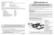
INSTALLATION AND MAINTENANCE INSTRUCTIONS<br />
<strong>DH100ACDC</strong> <strong>Air</strong> <strong>Duct</strong> <strong>Smoke</strong> <strong>Detector</strong><br />
Before Installing<br />
Please thoroughly read the System Sensor Guide for Proper<br />
Use of <strong>Smoke</strong> <strong>Detector</strong>s in <strong>Duct</strong> Applications (I56-473), which<br />
provides detailed information on detector spacing, placement,<br />
zoning, wiring, and special applications. Copies of this<br />
manual are available from System Sensor. NFPA Standards 72<br />
and 90A should also be referenced for detailed information.<br />
NOTICE: This manual should be left with the owner/user<br />
of this equipment.<br />
IMPORTANT: This detector must be tested and maintained<br />
regularly following NFPA 72 requirements. The detector<br />
should be cleaned at least once a year.<br />
Table of Contents Page<br />
[1] General Description 1<br />
[2] Limitations of <strong>Duct</strong> <strong>Smoke</strong> <strong>Detector</strong>s 1<br />
[3] Exploded View of <strong>Duct</strong> <strong>Smoke</strong> <strong>Detector</strong> Components 2<br />
[4] Contents of the <strong>Duct</strong> <strong>Smoke</strong> <strong>Detector</strong> Kit 2<br />
[5] Installation Sequence 2<br />
[6] <strong>Duct</strong> <strong>Smoke</strong> <strong>Detector</strong> Maintenance and Test Procedures 5<br />
[7] <strong>Detector</strong> Cleaning Procedures 7<br />
[8] Board Replacement 8<br />
[9] Specifications 8<br />
Warranty 8<br />
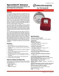
[1] General Description<br />
An HVAC system supplies conditioned air to virtually every<br />
area of a building. <strong>Smoke</strong> introduced into this air duct system<br />
will be distributed to the entire building. <strong>Smoke</strong> detectors<br />
designed for use in air duct systems are used to sense<br />
the presence of smoke in the duct.<br />
Model <strong>DH100ACDC</strong> <strong>Air</strong> <strong>Duct</strong> <strong>Smoke</strong> <strong>Detector</strong>s are supplied<br />
as an ionization model or photoelectronic model. These<br />
two smoke detection methods are combined with an efficient<br />
housing design that samples air passing through a<br />
duct and allows detection of a developing hazardous condition.<br />
When sufficient smoke is sensed, an alarm signal is<br />
initiated at the fire control panel monitoring the detector,<br />
and appropriate action can be taken to shut off fans, blowers,<br />
change over air handling systems, etc. These actions<br />
can facilitate the management of toxic smoke and fire gases<br />
throughout the areas served by the duct system.<br />
<strong>DH100ACDC</strong> detectors are designed to operate on 24 VDC/<br />
VAC, 120 VAC, or 240 VAC. Alarm and supervisory relay con-<br />
A Division of Pittway<br />
3825 Ohio Avenue, St. Charles, Illinois 60174<br />
1-800-SENSOR2, FAX: 630-377-6495<br />
tacts are available for control panel interface (alarm initiation),<br />
HVAC control, and other auxiliary functions. Auxiliary<br />
relays are also provided for fan shut down or signaling of up<br />
to 9 other detectors in the loop for multiple fan shut down.<br />
These detectors are not designed for 2-wire applications.<br />
For testing, the alarm can be enabled by a magnet activated<br />
test switch or by the optional remote test station.<br />
The duct smoke detector latches into alarm state when an<br />
alarm occurs. A green LED flashes to indicate power, a<br />
red LED signals local alarm indication, and optional accessories<br />
offer a variety of annunciation capabilities.<br />
The <strong>DH100ACDC</strong> can be reset by a momentary power interruption,<br />
the reset button on the front cover, the control<br />
panel, or remote reset accessory.<br />
[2] Limitations Of <strong>Duct</strong> <strong>Smoke</strong> <strong>Detector</strong>s<br />
WARNING<br />
The National <strong>Fire</strong> Protection Association has established<br />
that DUCT DETECTORS MUST NOT BE USED AS A SUB-<br />
STITUTE FOR OPEN AREA DETECTOR PROTECTION as a<br />
means of providing life safety. Nor are they a substitute for<br />
early warning in a building’s regular fire detection system.<br />
System Sensor supports this position and strongly recommends<br />
that the user read NFPA Standards 90A, 72, and 101. The<br />
<strong>DH100ACDC</strong> <strong>Air</strong> <strong>Duct</strong> <strong>Smoke</strong> <strong>Detector</strong>s are listed per UL 268A.<br />
WARNING<br />
This device will not operate without electrical power.<br />
<strong>Fire</strong> situations may cause an interruption of power. The<br />
system safeguards should be discussed with your local fire<br />
protection specialist.<br />
WARNING<br />
This device will not sense smoke unless the ventilation system<br />
is operating and the cover is installed.<br />
WARNING<br />
For this detector to function properly, it MUST be installed<br />
according to the instructions in this manual. Furthermore,<br />
the detector MUST be protected from the elements and operated<br />
within ALL electrical and environmental specifications<br />
listed in this manual. Failure to comply with these<br />
requirements may prevent the detector from activating<br />
when smoke is present in the air duct.<br />
D100-68-00 1 I56-1147-07
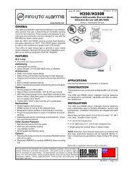
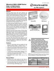
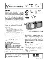
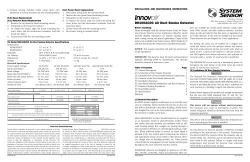
[3] Figure 1: Exploded View Of <strong>Duct</strong> <strong>Smoke</strong> <strong>Detector</strong> Components<br />
TELESCOPING TUBE<br />
FOAM<br />
GASKETS<br />
TELESCOPING TUBE<br />
SELF-TAPPING SCREW<br />
DETECTOR BOARD<br />
SAMPLING TUBE<br />
FILTERS<br />
DETECTOR<br />
COVER<br />
CONDUIT HOLES<br />
COVER MOUNTING<br />
SCREWS<br />
[4] Contents Of The <strong>Duct</strong> <strong>Smoke</strong> <strong>Detector</strong> Kit<br />
1. Complete housing base and cover assembly<br />
2. Two #10 machine screws for mounting<br />
3. Two sampling tube filters<br />
4. One test magnet<br />
5. Drilling template<br />
6. Two foam gaskets<br />
7. Four #6-self tapping mounting screws for the metal<br />
sampling tube and optional exhaust tube extension<br />
8. Two jack nuts<br />
9. One inlet tube end plug<br />
10. One telescoping sampling tube<br />
11. One #8 self-tapping screw for the telescoping sampling<br />
tube<br />
NOTE: For ducts over 1 1 /2 feet, longer inlet sampling tubes<br />
must be ordered to complete the installation. They<br />
must be the correct length for the width of the duct<br />
where they will be installed. See Table 1 on page 3<br />
to determine the inlet tube required for different<br />
duct widths.<br />
[5] Installation Sequence<br />
[5.1] Verify <strong>Duct</strong> <strong>Air</strong> Flow Direction And Velocity<br />
Model <strong>DH100ACDC</strong> detectors are designed to be used in air<br />
handling systems having air velocities of 500 to 4000 feet<br />
per minute. Be sure to check engineering specifications to<br />
ensure that the air velocity in the duct falls within these parameters.<br />
If necessary, use a velocity meter to check the air<br />
velocity in the duct.<br />
[5.2] Drill The Mounting Holes<br />
Remove the paper backing from the mounting template<br />
supplied. Affix the template to the duct at the desired<br />
mounting location. Make sure the template lies flat and<br />
DETECTOR<br />
HOUSING<br />
TERMINAL STRIP<br />
POWER BOARD<br />
Tube Installation Chart:<br />
Supplemental <strong>Duct</strong><br />
Tube Holes Width<br />
5 12″-14″<br />
6 14″-16″<br />
7 16″-18″<br />
smooth on the duct. Center punch holes A and B. Drill the<br />
holes as indicated on the template. Insert the two jack nut<br />
receptacles. Drive a #10 machine screw into jacket to flare<br />
the retainer, then back out the screw to use for detector<br />
mounting.<br />
[5.2.1] Sampling Tube Installation for <strong>Duct</strong>s Less<br />
Than 1 1 /2 Feet Wide (see Figure 2)<br />
1. Remove the front cover.<br />
2. Use the tube installation chart above to determine the<br />
set screw setting.<br />
3. Slide the sampling tube into the housing bushing.<br />
4. Align the holes in the bushing with the holes in the<br />
sampling tube. Make sure the number of exposed holes<br />
on the supplemental tube matches the number as determined<br />
in step 2. Secure with the #8 self-tapping screw<br />
into the bottom of the permanent tube.<br />
NOTE: For ducts greater than 1 1 /2 feet in width, refer to<br />
sections [5.4.1] and [5.4.2].<br />
Figure 2. Sampling tube connected to duct smoke<br />
detector:<br />
[5.3] Secure The <strong>Detector</strong> Housing To The <strong>Duct</strong><br />
Slide the foam gaskets over the tube bushings as shown in<br />
Figure 3. Use the two machine screws to screw the detector<br />
D100-68-00 2 I56-1147-07<br />
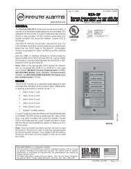
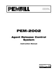
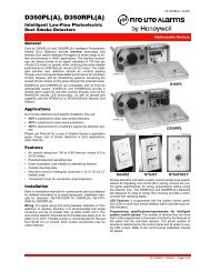
Figure 10. Wiring diagrams for optional accessories (see page 6 for APA451 wiring diagram):<br />
ALARM SIGNAL (+)<br />
AUX POWER (–)<br />
DUCT DETECTOR<br />
<strong>DH100ACDC</strong><br />
Figure 11. Testing detector alarm:<br />
A78-2325-00<br />
[6.2.2.2] RTS451/RTS451KEY Remote Test Station<br />
The RTS451/RTS451KEY Remote Test Station facilitates<br />
test of the alarm capability of the duct smoke detector<br />
as indicated in the RTS451/RTS451KEY manual. The<br />
<strong>DH100ACDC</strong> duct smoke detector can be reset by the<br />
RTS451/RTS451KEY. If a system control panel is used,<br />
the panel itself may also require testing.<br />
To install the RTS451/RTS451KEY, connect the device as<br />
shown in Figure 9; wire runs must be limited to 25 ohms or<br />
less per interconnecting wire.<br />
[6.2.3] Sensitivity Tests<br />
[6.2.3.1] MOD400 or MOD400R Test<br />
After verification of alarm capability, use the MOD400R test<br />
module with a voltmeter to check detector sensitivity as indicated<br />
in the test module’s manual. The housing cover<br />
must be removed to perform this test.<br />
15<br />
20<br />
(+)<br />
(–)<br />
PA400 (OPTIONAL)<br />
AUDIBLE ALERT<br />
ACCESSORY CURRENT LOADS AT 24 VDC<br />
DEVICE<br />
STANDBY ALARM<br />
APA451<br />
12.5mA Max. 30mA Max.<br />
PA400<br />
0mA 15mA Max.<br />
RA400Z<br />
0mA 10mA Max.<br />
RTS451/RTS451KEY 12mA Max. 7.5mA Max.<br />
When a unit is powered at the 120VAC or 220/240VAC input,<br />
any combination of accessories may be used such that the given<br />
accessory loads are:<br />
60mA or less in the standby state,<br />
110mA or less in the alarm state.<br />
ALARM SIGNAL (+)<br />
AUX POWER (–)<br />
DUCT DETECTOR<br />
<strong>DH100ACDC</strong><br />
If test module readings indicate that the detector head is<br />
outside of the acceptable range that is printed on the label<br />
of the detector, the detector chamber requires cleaning per<br />
Section [7] of this manual.<br />
[7] <strong>Detector</strong> Cleaning Procedures<br />
Notify the proper authorities that the smoke detector system<br />
is undergoing maintenance, and that the system will<br />
temporarily be out of service. Disable the zone or system<br />
undergoing maintenance to prevent unwanted alarms and<br />
possible dispatch of the fire department.<br />
[7.1] <strong>Air</strong> Filters<br />
1. Turn off power to the system.<br />
2. Remove and inspect sampling tube filters.<br />
3. If filters are heavily coated with dirt, replace them with<br />
new filters. If they are not heavily coated, use a vacuum<br />
cleaner or compressed air nozzle to remove dust, then<br />
reinstall the filters.<br />
[7.2] Photo <strong>Detector</strong> Boards<br />
1. Remove the screen by gently grasping on each side and<br />
pulling straight off.<br />
2. Lift the photo chamber in the same fashion. Vacuum the<br />
screen and cover. Use clean, compressed air to loosen<br />
and blow out any remaining debris. Replacement<br />
screens (S08-39-01) are available.<br />
3. Vacuum photo chamber, then use clean compressed air<br />
to blow area clean.<br />
4. Replace the chamber by pressing it onto the base.<br />
Press the screen into place. It should fit tightly on the<br />
chamber.<br />
[7.3] Ion <strong>Detector</strong> Boards<br />
1. Brush or vacuum inside area of cover. Chamber may<br />
then be blown out using clean, compressed air.<br />
D100-68-00 7 I56-1147-07<br />
15<br />
20<br />
(+)<br />
(–)<br />
RED<br />
RA400Z (OPTIONAL)<br />
REMOTE (LED)<br />
ANNUNCIATOR<br />
A78-2354-05
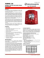
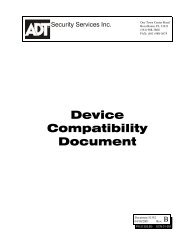
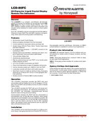
Figure 7. System wiring diagram for 4-wire duct smoke detectors (detectors powered from initiating circuit):<br />
POWER INPUTS ACCEPT<br />
24 VDC, 24 VAC 50-60 HZ,<br />
120 VAC 50-60 HZ, OR<br />
220/240 VAC 50-60 HZ.<br />
CONNECT POWER SOURCE<br />
TO APPROPRIATE TERMINALS<br />
OF EACH DETECTOR.<br />
AUX. CONTACT RATINGS<br />
10A @ 30 VDC RESISTIVE<br />
10A @ 250 VAC<br />
100mA MINIMUM @ 5 VDC<br />
NOT INTENDED FOR<br />
CONNECTION TO CONTROL<br />
PANELS.<br />
TROUBLE CONTACT RATING<br />
2.0 A @ 30 VDC resistive<br />
ALARM<br />
INITIATION<br />
LOOP<br />
+<br />
—<br />
UL LISTED 4-WIRE<br />
CONTROL PANEL<br />
N.C.<br />
AVAILABLE POWER INPUTS<br />
9 10 A B C<br />
24V<br />
120<br />
VAC<br />
220/240<br />
VAC<br />
ALARM AUXILIARY CONTACTS<br />
FOR FAN SHUTDOWN, ETC.<br />
16 6 17 7 18 8<br />
C.<br />
N.O.<br />
N.O.<br />
ALARM AUXILIARY CONTACTS SHOWN IN<br />
STANDBY. CONTACTS TRANSFER DURING<br />
ALARM AS INDICATED BY THE ARROWS.<br />
C.<br />
SUPERVISORY TROUBLE CONTACTS<br />
N.C.<br />
TROUBLE CONTACTS CLOSED IN ALARM AND STANDBY.<br />
CONTACTS OPEN WHILE DETECTOR HEAD OR POWER IS<br />
REMOVED OR WHEN TAMPER FEATURE TIMES OUT. OPEN<br />
CONTACTS SIGNAL TROUBLE CONDITION TO PANEL.<br />
ALARM<br />
INITIATION<br />
CONTACTS<br />
D100-68-00 6 I56-1147-07<br />
N.C.<br />
AVAILABLE POWER INPUTS<br />
9 10 A B C<br />
24V<br />
220/240<br />
VAC<br />
ALARM AUXILIARY CONTACTS<br />
FOR FAN SHUTDOWN, ETC.<br />
16 6 17 7 18 8<br />
C.<br />
N.O.<br />
N.O.<br />
ALARM AUXILIARY CONTACTS SHOWN IN<br />
STANDBY. CONTACTS TRANSFER DURING<br />
ALARM AS INDICATED BY THE ARROWS.<br />
C.<br />
SUPERVISORY TROUBLE CONTACTS<br />
3 14 3 14<br />
4<br />
5<br />
CONTACTS SHOWN<br />
OPEN IN STANDBY.<br />
CONTACTS CLOSE<br />
IN ALARM.<br />
FIRST DETECTOR IN THE LOOP<br />
<strong>DH100ACDC</strong><br />
CAUTION<br />
Do not loop wire under terminals when wiring detectors. Break wire runs to provide system supervision of connections.<br />
Figure 8. Wiring diagram for <strong>DH100ACDC</strong> to APA451:<br />
<strong>DH100ACDC</strong><br />
Alarm Signal<br />
Aux. Power +<br />
Sup. N. O.<br />
Sup. COM<br />
Aux. Power –<br />
15<br />
19<br />
14<br />
3<br />
20<br />
2<br />
3<br />
1<br />
APA451<br />
Alarm<br />
Power<br />
Common<br />
NOTE: Wiring diagram shown is for <strong>DH100ACDC</strong> 4-wire duct<br />
smoke detector system equipped without a control panel.<br />
N.C.<br />
TROUBLE CONTACTS CLOSED IN ALARM AND STANDBY.<br />
CONTACTS OPEN WHILE DETECTOR HEAD OR POWER IS<br />
REMOVED OR WHEN TAMPER FEATURE TIMES OUT. OPEN<br />
CONTACTS SIGNAL TROUBLE CONDITION TO PANEL.<br />
ALARM<br />
INITIATION<br />
CONTACTS<br />
4<br />
5<br />
120<br />
VAC<br />
CONTACTS SHOWN<br />
OPEN IN STANDBY.<br />
CONTACTS CLOSE<br />
IN ALARM.<br />
LAST DETECTOR IN THE LOOP<br />
<strong>DH100ACDC</strong><br />
CONNECT POWER SOURCE<br />
TO APPROPRIATE TERMINALS<br />
OF EACH DETECTOR. SEE<br />
SPECIFICATIONS FOR<br />
ADDITIONAL POWER SUPPLY<br />
INFORMATION.<br />
FOR WIRING OF AUXILIARY<br />
DEVICES, REFER TO<br />
MANUFACTURER’S<br />
INSTALLATION INSTRUCTIONS<br />
OR CONTACT MANUFACTURER.<br />
NOTE: THE SUPERVISORY RELAY NOW<br />
PROVIDES A "FORM C" CONTACT FOR<br />
CUSTOMIZED APPLICATIONS.<br />
FOR STANDARD APPLICATIONS, ONLY<br />
THE "NO" CONTACT IS USED<br />
Figure 9. Wiring diagram for <strong>DH100ACDC</strong> to<br />
RTS451KEY and interconnect feature:<br />
<strong>DH100ACDC</strong><br />
Alarm Signal<br />
Aux. Power +<br />
Sup. N. O.<br />
Sup. COM<br />
Aux. Power –<br />
Reset<br />
Test<br />
Interconnect +<br />
Interconnect –<br />
<strong>DH100ACDC</strong><br />
Unit Two<br />
15<br />
19<br />
14<br />
3<br />
20<br />
2<br />
11<br />
12<br />
1<br />
12<br />
1<br />
1<br />
6<br />
2<br />
EOL RESISTOR<br />
SPECIFIED BY<br />
PANEL MANUFACTURER<br />
RTS451KEY<br />
(Red LED) Alarm<br />
(Green LED) Power<br />
Common<br />
3 Reset<br />
4<br />
5<br />
Common<br />
Test<br />
A78-2352-03<br />
NOTE: Wiring diagram shown is for<br />
<strong>DH100ACDC</strong> 4-wire duct smoke<br />
detector system equipped<br />
without a control panel.<br />
IMPORTANT!<br />
ALL INTERCONNECTED<br />
UNITS MUST BE POWERED<br />
BY THE SAME,<br />
INDEPENDENT POWER<br />
SUPPLY.<br />
housing to the duct.<br />
CAUTION: Do not overtighten the screws.<br />
Figure 3. Installation of foam gaskets over sampling<br />
tube bushings:<br />
SCREW HOLES FOR<br />
ATTACHING HOUSING<br />
TO DUCT WORK.<br />
A78-2045-00<br />
[5.4] Sampling Tube Installation for <strong>Duct</strong>s Greater<br />
Than 1 1 /2 Feet Wide<br />
The sampling tube is identified by a series of air inlet holes<br />
on the tube. A telescoping tube is included for ducts up to<br />
18″ in width. All other lengths must be purchased separately.<br />
Order the correct length, as specified in Table 1, for<br />
width of the duct where it will be installed. The exhaust<br />
tube is molded onto the base of the duct housing, and the<br />
A2440-00 Exhaust Tube Extension is available as an accessory<br />
in those cases where the molded exhaust port does not<br />
extend at least 2 inches into the duct.<br />
The inlet tube is always installed with the air inlet holes<br />
facing into the air flow. To assist proper installation, the<br />
tube’s mounting flange is marked with arrows. Make sure<br />
the inlet tube is mounted so that the arrows point into the<br />
air flow (see Figure 4). Figure 5 shows the various combinations<br />
of tube mounting configurations with respect to air<br />
flow. Mounting the detector housing in a vertical orientation<br />
is acceptable, provided that the air flows directly into<br />
the sampling tube holes as indicated in Figure 4.<br />
Table 1. Inlet tubes required for different duct<br />
widths:<br />
Outside <strong>Duct</strong> Width Inlet Tube Required<br />
1 to 2 ft. ST-1.5<br />
2 to 4 ft. ST-3<br />
4 to 8 ft. ST-5<br />
8 to 12 ft. ST-10<br />
[5.4.1] Installation For <strong>Duct</strong>s Greater Than 1 1 /2 Feet<br />
But Less Than 8 Feet Wide<br />
1. If the tube is longer than the width of the air duct, drill a<br />
3 /4″ hole in the duct opposite the hole already cut for the<br />
inlet tube. Make sure the hole is 1″ to 2″ below the inlet<br />
hole on the opposite side of the duct to allow moisture<br />
drainage away from the detector. If the tube is shorter than<br />
the width of the air duct, install the end plug into the inlet<br />
tube as shown in Figure 4. Sampling tubes over 3 ft. long<br />
must be supported at the end opposite the duct detector.<br />
2. Slide the tube into the housing bushing that meets the<br />
air flow first. Position the tube so that the arrows point<br />
into the air flow.<br />
3. Secure the tube flange to the housing bushing with two<br />
#6 self-tapping screws.<br />
4. For tubes longer than the width of the air duct, the tube<br />
should extend out of the opposite side of the duct. If<br />
there are more than 2 holes in the section of the tube extending<br />
out of the duct, select a different length using<br />
Table 1. Otherwise, trim the end of the tube protruding<br />
through the duct so that 1″ to 2″ of the tube extend outside<br />
the duct. Plug this end with the end plug and tape<br />
closed any holes in the protruding section of the tube. Be<br />
sure to seal the duct where the tube protrudes.<br />
Figure 4. <strong>Air</strong> duct detector inlet sampling tube:<br />
FLANGE<br />
A78-2047-00<br />
Figure 5. Tube mounting configurations with varying<br />
air flow direction:<br />
AIR FLOW<br />
DIRECTION<br />
DUCT<br />
DETECTOR<br />
HOUSING<br />
DUCT<br />
DETECTOR<br />
HOUSING<br />
INLET<br />
TUBE<br />
EXHAUST<br />
TUBE<br />
AIR HOLES<br />
ARROWS<br />
MUST FACE<br />
INTO AIR FLOW<br />
EXHAUST<br />
TUBE<br />
INLET<br />
TUBE<br />
AIR FLOW<br />
DIRECTION<br />
DOTS INDICATE POSITION OF<br />
SAMPLING TUBE HOLES<br />
A.<br />
C.<br />
EXHAUST<br />
TUBE<br />
EXHAUST<br />
TUBE<br />
AIR FLOW<br />
DIRECTION<br />
INLET<br />
TUBE<br />
INLET<br />
TUBE<br />
NOTE: Orientations C and D apply only to metal sampling tubes.<br />
WARNING<br />
AIR FLOW DIRECTION<br />
AIR FLOW<br />
DIRECTION<br />
DUCT<br />
DETECTOR<br />
HOUSING<br />
B.<br />
DUCT<br />
DETECTOR<br />
HOUSING<br />
In no case should more than 2 air inlet holes be cut off the<br />
tube. There must be a minimum of 10 holes in the tube exposed<br />
to the air stream.<br />
[5.4.2] Installation For <strong>Duct</strong>s More Than 8 Feet Wide<br />
NOTE: To install inlet tubes in ducts more than 8 feet wide,<br />
D100-68-00 3 I56-1147-07<br />
D.<br />
INLET<br />
TUBE<br />
END<br />
PLUG
work must be performed inside the air duct. Sampling<br />
of air in ducts wider than 8 feet is accomplished by<br />
using the ST-10 inlet sampling tube. If the tube is<br />
shorter than the width of the air duct, install the end<br />
plug into the inlet tube as shown in Figure 4 and support<br />
the end opposite the duct smoke detector.<br />
Install the inlet tube as follows:<br />
1. Drill a 3 /4-inch hole in the duct directly opposite the hole<br />
already drilled for the inlet tube. Make sure the hole is 1<br />
to 2″ below the inlet hole on the opposite side of the<br />
duct to allow for moisture drainage.<br />
2. Slide the inlet tube with the flange into the housing<br />
bushing that meets the air flow first. Position the tube so<br />
that the arrows point into the air flow. Secure the tube<br />
flange to the housing bushing with two #6 self-tapping<br />
screws.<br />
3. From inside the duct, couple the other sections of the inlet<br />
tube to the section already installed using the 1 /2-inch<br />
conduit fittings supplied. Make sure that the holes on<br />
both of the air inlet tubes are lined up and facing into<br />
the air flow.<br />
4. Trim the end of the tube protruding through the duct so<br />
that 1 to 2″ of the tube extend outside the duct. Plug this<br />
end with the end plug and tape closed any holes in the<br />
protruding section of the tube. Be sure to seal the duct<br />
when the tube protrudes.<br />
NOTE: An alternate method to using the ST-10 is to use<br />
two ST-5 inlet tubes. Remove the flange from one<br />
of the tubes and install as described above. After<br />
the installation, use electrical tape to close off<br />
some of the sampling holes so that there are a total<br />
of 10 to 12 holes spaced as evenly as possible<br />
across the width of the duct.<br />
NOTE: <strong>Air</strong> currents inside the duct may cause excessive<br />
vibration, especially when the longer sampling<br />
tubes are used. In these cases a 3 inch floor flange<br />
(available at most plumbing supply stores) may be<br />
used to fasten the sampling tube to the other side<br />
of the duct. When using the flange/connector<br />
mounting technique, drill a 1-inch to 1 1 /4-inch hole<br />
where the flange will be used.<br />
[5.4.3] Modifications of Inlet Sampling Tubes<br />
There may be applications where duct widths are not what<br />
is specified for the installation. In such cases, it is permissible<br />
to modify an inlet sampling tube that is longer than<br />
necessary to span the duct width.<br />
Use a 0.193-inch diameter (#11) drill and add the appropriate<br />
number of holes so that the total number of holes exposed to<br />
the air flow in the duct is 10 to 12. Space the additional holes<br />
as evenly as possible over the length of the tube.<br />
NOTE: This procedure should only be used as a temporary<br />
fix. It is not intended as a permanent substitute for<br />
ordering the correct length tubes.<br />
[5.5] Install The Filters<br />
To install the sampling tube filters, simply push the filters<br />
into the sampling and exhaust tube holes, as shown in Figure<br />
6. If a metal sampling tube is used, install the filters<br />
over the tube ends.<br />
Figure 6. Sampling tube filter installation:<br />
CAUTION<br />
A78-2106-01<br />
Filters require periodic cleaning or replacement, depending<br />
on the amount of dust and dirt accumulated. Visually inspect<br />
the filters at least quarterly; inspect them more often<br />
if the dust accumulation warrants it. See Section [6] for<br />
more information. Replacement filters can be ordered from<br />
System Sensor, 3825 Ohio Ave., St. Charles, IL 60174. (Exhaust<br />
tube/intake tube filter P/N F36-09-00)<br />
[5.6] Field Wiring<br />
Wiring Installation Guidelines<br />
All wiring must be installed in compliance with the National<br />
Electrical Code and the local codes having jurisdiction.<br />
Proper wire gauges should be used. The conductors<br />
used to connect smoke detectors to control panels and accessory<br />
devices should be color-coded to prevent wiring<br />
mistakes. Improper connections can prevent a system from<br />
responding properly in the event of a fire.<br />
For signal wiring, (the wiring between interconnected detectors<br />
or from detectors to auxiliary devices), it is usually<br />
recommended that single conductor wire be no smaller<br />
than 18 gauge. The duct smoke detector terminals accommodate<br />
wire sizes up to 12 gauge. The last foot of conduit<br />
should be flexible conduit (available in electrical supply<br />
houses), which facilitates easier installation and puts less<br />
strain on the conduit holes in the housing. Solid conduit<br />
connections may be used if desired.<br />
D100-68-00 4 I56-1147-07<br />
<strong>Smoke</strong> detectors and alarm system control panels have<br />
specifications for allowable loop resistance. Consult the<br />
control panel manufacturer’s specifications for the total<br />
loop resistance allowed for the particular model control<br />
panel being used before wiring the detector loop.<br />
Wiring Instructions<br />
The <strong>DH100ACDC</strong> detectors are designed for easy wiring.<br />
The housing provides a terminal strip with clamping<br />
plates. Wiring connections are made by stripping about<br />
3 /8-inch of insulation from the end of the wire, sliding<br />
the bare end under the plate, and tightening the clamping<br />
plate screw.<br />
[5.7] Perform <strong>Detector</strong> Check<br />
1. Perform STANDBY AND TROUBLE TEST per Section<br />
[6.2.1].<br />
2. Perform MAGNET TEST per Section [6.2.2.1]. The<br />
RTS451 test of Section [6.2.2.2] may substitute for this<br />
requirement.<br />
3. Perform AIR FLOW TEST per Section [6.1.1].<br />
4. Perform SMOKE RESPONSE TEST per Section [6.1.2].<br />
5. Perform SENSITIVITY TEST per Section [6.2.3].<br />
[5.8] Install The Cover<br />
Install the cover using the four screws that are captured in<br />
the housing cover. Be certain filters are installed as specified<br />
in Section [5.5]. Make sure that the cover fits into the<br />
base groove and that all gaskets are in their proper positions.<br />
Tighten the four screws.<br />
[6] <strong>Duct</strong> <strong>Smoke</strong> <strong>Detector</strong> Maintenance And Test<br />
Procedures<br />
Test and maintain duct detectors as recommended in NFPA<br />
72. The tests contained in this manual were devised to assist<br />
maintenance personnel in verification of proper detector<br />
operation.<br />
Before conducting these tests, notify the proper authorities<br />
that the smoke detection system will be temporarily out of<br />
service. Disable the zone or system under test to prevent<br />
unwanted alarms.<br />
[6.1] <strong>Smoke</strong> Entry Tests<br />
[6.1.1] <strong>Air</strong> Flow<br />
To verify sufficient sampling of ducted air, use a manometer<br />
to measure the differential pressure created from air flow<br />
across the sampling tubes. The pressure should measure no<br />
less than 0.03 inches of water and no greater than 1.4 inches<br />
of water. The air handler must be operating for this test.<br />
[6.1.2] <strong>Smoke</strong> Response<br />
To determine if smoke is capable of entering the sensing<br />
chamber, visually identify any obstructions. Plug the ex-<br />
haust and inlet tube holes to prevent ducted air from carrying<br />
smoke away from the detector head, then blow smoke<br />
such as cigarette, cotton wick, or punk directly at the head<br />
to cause an alarm. REMEMBER TO REMOVE THE PLUGS<br />
AFTER THIS TEST, OR THE DETECTOR WILL NOT FUNC-<br />
TION PROPERLY.<br />
[6.1.3] Filter Replacement<br />
The filters do not substantially affect smoke performance<br />
even when up to 90% of the filter is clogged. Quarterly visual<br />
inspection usually suffices to determine whether the<br />
filters should be replaced because only a high percentage of<br />
contamination affects performance. If further testing is required,<br />
compare differential pressure readings with and<br />
without the filters installed. If the difference exceeds 10%<br />
replace the filters. In no case should the pressure differential<br />
fall below 0.03 inches of water.<br />
[6.2] Standby, Alarm, And Sensitivity Tests<br />
[6.2.1] Standby And Trouble<br />
Standby — Look for the presence of the flashing green<br />
LED through the transparent housing cover.<br />
The LED should flash approximately every<br />
10 seconds.<br />
Trouble — If the detector LED does not flash, then the<br />
detector lacks power (check wiring, panel, or<br />
power supply), the detector board is missing<br />
(replace), or the unit is defective (return for<br />
repair)<br />
Test — The trouble condition can be caused intentionally<br />
to verify correct operation of the system.<br />
Remove the detector board to cause a<br />
trouble condition locally and at the system<br />
control panel.<br />
Cover<br />
Tamper — If the cover is removed for a period longer<br />
than 20 minutes, a trouble signal is generated<br />
to indicate the cover is missing.<br />
[6.2.2] Alarm Tests<br />
[6.2.2.1] M02-04-00 Magnet Test<br />
1. Place the painted surface of the magnet onto the TEST<br />
locator on the bottom of the housing (Figure 11).<br />
2. The red alarm LED on the detector should latch on, as<br />
should any accessories (i.e. RA400Z, RTS451). Verify<br />
system control panel alarm status and control panel execution<br />
of all intended auxiliary functions (i.e. fan shutdown,<br />
damper control, etc.).<br />
3. The detector must be reset by system control panel, front<br />
cover reset button, or remote accessory.<br />
D100-68-00 5 I56-1147-07