SLX Series 2000 Installation and Use Manual - Emerson Network ...
SLX Series 2000 Installation and Use Manual - Emerson Network ...
SLX Series 2000 Installation and Use Manual - Emerson Network ...

You also want an ePaper? Increase the reach of your titles
YUMPU automatically turns print PDFs into web optimized ePapers that Google loves.
<strong>SLX</strong> <strong>Series</strong> <strong>2000</strong> <strong>Installation</strong><br />
<strong>and</strong> <strong>Use</strong> <strong>Manual</strong><br />
<strong>SLX</strong>A/IH1<br />
September 1999
Notice<br />
While reasonable efforts have been made to assure the accuracy of this document,<br />
Motorola, Inc. assumes no liability resulting from any omissions in this document, or from<br />
the use of the information obtained therein. Motorola reserves the right to revise this<br />
document <strong>and</strong> to make changes from time to time in the content hereof without obligation<br />
of Motorola to notify any person of such revision or changes.<br />
Electronic versions of this material may be read online, downloaded for personal use, or<br />
included in another document as a URL from the Motorola Computer Group website. The<br />
text itself may not be published commercially in print or electronic form, edited, translated,<br />
or otherwise altered without the permission of Motorola, Inc.<br />
It is possible that this publication may contain reference to or information about Motorola<br />
products (machines <strong>and</strong> programs), programming, or services that are not announced in<br />
your country. Such references or information must not be construed to mean that Motorola<br />
intends to announce such Motorola products, programming, or services in your country.<br />
Restricted Rights Legend<br />
If the documentation contained herein is supplied, directly or indirectly, to the U.S.<br />
Government, the following notice shall apply unless otherwise agreed to in writing by<br />
Motorola, Inc.<br />
<strong>Use</strong>, duplication, or disclosure by the Government is subject to restrictions as set forth in<br />
subparagraph (c)(1)(ii) of the Rights in Technical Data <strong>and</strong> Computer Software clause at<br />
DFARS 252.227-7013.<br />
Motorola, Inc.<br />
Computer Group<br />
2900 South Diablo Way<br />
Tempe, Arizona 85282<br />
Motorola ® <strong>and</strong> the Motorola symbol are registered trademarks of Motorola, Inc.<br />
All other products mentioned in this document are trademarks or registered trademarks of<br />
their respective holders.<br />
© Copyright Motorola, Inc. 1999<br />
All Rights Reserved<br />
Printed in the United States of America
Preface<br />
The <strong>SLX</strong> <strong>Series</strong> <strong>Installation</strong> <strong>and</strong> <strong>Use</strong> <strong>Manual</strong> provides technical specifications of the <strong>SLX</strong><br />
<strong>Series</strong> as well as describing the recommended procedures for installing <strong>and</strong> upgrading the<br />
system.<br />
Summary of Changes<br />
The following table provides a summary of changes that have been made to this manual <strong>and</strong><br />
the dates they have been made.<br />
Change Date<br />
Added Illustration of the AGP <strong>and</strong> PCI<br />
Risers on Figure 3-4<br />
September 1999<br />
Original Publication August 1999
Safety Summary<br />
Safety Depends On You<br />
The following general safety precautions must be observed during all phases of operation, service, <strong>and</strong> repair of this<br />
equipment. Failure to comply with these precautions or with specific warnings elsewhere in this manual violates safety<br />
st<strong>and</strong>ards of design, manufacture, <strong>and</strong> intended use of the equipment. Motorola, Inc. assumes no liability for the<br />
customer’s failure to comply with these requirements.<br />
The safety precautions listed below represent warnings of certain dangers of which Motorola is aware. You, as the<br />
user of the product, should follow these warnings <strong>and</strong> all other safety precautions necessary for the safe operation of<br />
the equipment in your operating environment.<br />
Ground the Instrument.<br />
To minimize shock hazard, the equipment chassis <strong>and</strong> enclosure must be connected to an electrical ground. The<br />
equipment is supplied with a three-conductor ac power cable. The power cable must be plugged into an approved<br />
three-contact electrical outlet. The power jack <strong>and</strong> mating plug of the power cable meet International Electrotechnical<br />
Commission (IEC) safety st<strong>and</strong>ards.<br />
Do Not Operate in an Explosive Atmosphere.<br />
Do not operate the equipment in the presence of flammable gases or fumes. Operation of any electrical equipment in<br />
such an environment constitutes a definite safety hazard.<br />
Keep Away From Live Circuits.<br />
Operating personnel must not remove equipment covers. Only Factory Authorized Service Personnel or other<br />
qualified maintenance personnel may remove equipment covers for internal subassembly or component replacement<br />
or any internal adjustment. Do not replace components with power cable connected. Under certain conditions,<br />
dangerous voltages may exist even with the power cable removed. To avoid injuries, always disconnect power <strong>and</strong><br />
discharge circuits before touching them.<br />
Do Not Service or Adjust Alone.<br />
Do not attempt internal service or adjustment unless another person capable of rendering first aid <strong>and</strong> resuscitation is<br />
present.<br />
<strong>Use</strong> Caution When Exposing or H<strong>and</strong>ling the CRT.<br />
Breakage of the Cathode-Ray Tube (CRT) causes a high-velocity scattering of glass fragments (implosion). To<br />
prevent CRT implosion, avoid rough h<strong>and</strong>ling or jarring of the equipment. H<strong>and</strong>ling of the CRT should be done only<br />
by qualified maintenance personnel using approved safety mask <strong>and</strong> gloves.<br />
Do Not Substitute Parts or Modify Equipment.<br />
Because of the danger of introducing additional hazards, do not install substitute parts or perform any unauthorized<br />
modification of the equipment. Contact your local Motorola representative for service <strong>and</strong> repair to ensure that safety<br />
features are maintained.<br />
Dangerous Procedure Warnings.<br />
Warnings, such as the example below, precede potentially dangerous procedures throughout this manual. Instructions<br />
contained in the warnings must be followed. You should also employ all other safety precautions which you deem<br />
necessary for the operation of the equipment in your operating environment.<br />
!<br />
Warning<br />
Dangerous voltages, capable of causing death, are present in<br />
this equipment. <strong>Use</strong> extreme caution when h<strong>and</strong>ling, testing,<br />
<strong>and</strong> adjusting.
Flammability<br />
All Motorola PWBs (printed wiring boards) are manufactured with a flammability rating<br />
of 94V-0 by UL-recognized manufacturers.<br />
EMI Caution<br />
!<br />
Caution<br />
Lithium Battery Caution<br />
This equipment generates, uses <strong>and</strong> can radiate<br />
electromagnetic energy. It may cause or be susceptible to<br />
electromagnetic interference (EMI) if not installed <strong>and</strong> used in<br />
a cabinet with adequate EMI protection.<br />
This equipment generates, uses <strong>and</strong> can radiate<br />
electromagnetic energy. It may cause or be susceptible to<br />
electromagnetic interference (EMI) if not installed <strong>and</strong> used in<br />
a cabinet with adequate EMI protection.<br />
This product contains a lithium battery to power the clock <strong>and</strong> calendar circuitry.<br />
Caution<br />
!<br />
Caution<br />
Caution<br />
!<br />
Attention<br />
Caution<br />
!<br />
Vorsicht<br />
Danger of explosion if battery is replaced incorrectly. Replace<br />
battery only with the same or equivalent type recommended<br />
by the equipment manufacturer. Dispose of used batteries<br />
according to the manufacturer’s instructions.<br />
Il y a danger d’explosion s’il y a remplacement incorrect de la<br />
batterie. Remplacer uniquement avec une batterie du même<br />
type ou d’un type équivalent recomm<strong>and</strong>é par le constructeur.<br />
Mettre au rebut les batteries usagées conformément aux<br />
instructions du fabricant.<br />
Explosionsgefahr bei unsachgemäßem Austausch der<br />
Batterie. Ersatz nur durch denselben oder einen vom<br />
Hersteller empfohlenen Typ. Entsorgung gebrauchter<br />
Batterien nach Angaben des Herstellers.
CE Notice (European Community)<br />
Warning<br />
!<br />
Warning<br />
This is a Class A product. In a domestic environment, this<br />
product may cause radio interference, in which case the user<br />
may be required to take adequate measures.<br />
Motorola Computer Group products with the CE marking comply with the EMC Directive<br />
(89/336/EEC). Compliance with this directive implies conformity to the following<br />
European Norms:<br />
EN55022 “Limits <strong>and</strong> Methods of Measurement of Radio Interference Characteristics<br />
of Information Technology Equipment”; this product tested to Equipment Class A<br />
EN50082-1:1997 “Electromagnetic Compatibility—Generic Immunity St<strong>and</strong>ard,<br />
Part 1. Residential, Commercial <strong>and</strong> Light Industry”<br />
The product also fulfills EN60950 (product safety) which is essentially the requirement for<br />
the Low Voltage Directive (73/23/EEC).<br />
Board products are tested in a representative system to show compliance with the above<br />
mentioned requirements. A proper installation in a CE-marked system will maintain the<br />
required EMC/safety performance.<br />
In accordance with European Community directives, a “Declaration of Conformity” has<br />
been made <strong>and</strong> is on file at Motorola, Inc.—Computer Group, 27 Market Street,<br />
Maidenhead, United Kingdom, SL6 8AE.<br />
FCC Class A<br />
This equipment has been tested <strong>and</strong> found to comply with the limits for a Class A digital<br />
device, pursuant to Part 15 of the FCC Rules. These limits are designed to provide<br />
reasonable protection against harmful interference when the equipment is operated in a<br />
commercial environment. This equipment generates, uses, <strong>and</strong> can radiate radio frequency<br />
energy <strong>and</strong>, if not installed <strong>and</strong> used in accordance with the instruction manual, may cause<br />
harmful interference to radio communications. Operation of this equipment in a residential<br />
area is likely to cause harmful interference in which case the user will be required to correct<br />
the interference at his own expense.
Industrie Canada<br />
This product meets the requirements of the Canadian Interference-Causing Equipment<br />
St<strong>and</strong>ard ICES-003.<br />
Cet appareil numérique est conforme à la norme NMB-003 du Canada.
Contents<br />
CHAPTER 1 Introduction<br />
Who Should <strong>Use</strong> This Guide .....................................................................................1-1<br />
Product Description ...................................................................................................1-2<br />
Front Panel Features of the <strong>SLX</strong>2020.................................................................1-3<br />
Rear Panel Features of the <strong>SLX</strong>2020..................................................................1-4<br />
Related Documentation..............................................................................................1-5<br />
MCG Customer Services ...........................................................................................1-6<br />
CHAPTER 2 <strong>Installation</strong> Instructions for <strong>SLX</strong> <strong>Series</strong> Systems<br />
Receiving <strong>and</strong> Unpacking the System .......................................................................2-1<br />
Guidelines for Locating the System...........................................................................2-2<br />
Following ESD <strong>and</strong> Safety Procedures......................................................................2-2<br />
Grounding the <strong>SLX</strong>2020 System........................................................................2-3<br />
Safety <strong>and</strong> Regulatory Compliance ...........................................................................2-4<br />
Regulatory Notes .......................................................................................................2-4<br />
Lithium Battery Caution ............................................................................................2-4<br />
Environmental Considerations...................................................................................2-5<br />
Cooling the Enclosure................................................................................................2-5<br />
Power Circuit Loading Considerations ......................................................................2-5<br />
Installing an <strong>SLX</strong> <strong>Series</strong> System in a 19-Inch Rack ..................................................2-6<br />
Connecting the System ..............................................................................................2-8<br />
Turning On the AC System........................................................................................2-8<br />
CHAPTER 3 Upgrading Your System<br />
Introduction................................................................................................................3-1<br />
Installing a PCI Card..................................................................................................3-2<br />
Removing the Chassis Cover..............................................................................3-3<br />
Removing the Graphics Card..............................................................................3-4<br />
Removing the Expansion Slot Cover..................................................................3-5<br />
Inserting the PCI Card into the PCI Riser...........................................................3-6<br />
Installing the PCI Card <strong>and</strong> Riser into the <strong>SLX</strong>2020 Chassis ............................3-8<br />
Reinstalling the Graphics Card...........................................................................3-9<br />
Reinstalling the Chassis Cover .........................................................................3-10<br />
ix
x<br />
Installing Additional Memory Modules .................................................................. 3-11<br />
Removing the Chassis Cover ........................................................................... 3-12<br />
Installing Additional Memory Modules ........................................................... 3-13<br />
Reinstalling the Chassis Cover......................................................................... 3-14<br />
APPENDIX A System Specifications<br />
Specifications for the <strong>SLX</strong>2020 ............................................................................... A-1<br />
Chassis Specifications .............................................................................................. A-2<br />
Environmental <strong>and</strong> Regulatory Specifications ......................................................... A-4<br />
APPENDIX B <strong>Installation</strong>sanweisung für Systeme der Serie <strong>SLX</strong><br />
Empfangen und Auspacken des Systems ................................................................. B-1<br />
Richtlinien zum Aufstellen des Systems .................................................................. B-1<br />
ESE- und Sicherheitsmaßnahmen ............................................................................ B-2<br />
Sicherheit und Approbationen .................................................................................. B-3<br />
Vorsichtshinweis zur Lithium-Batterie..................................................................... B-3<br />
Berücksichtigungen bei Wahl der Betriebsumgebung.............................................. B-4<br />
Kühlen des Gehäuses................................................................................................ B-4<br />
Berücksichtigungen zur Stromkreisbelastung .......................................................... B-4<br />
Einbau eines <strong>SLX</strong>-Serie-Systems in ein 19-Zoll-Rack ............................................ B-5<br />
Anschließen des Systems.......................................................................................... B-5<br />
Einschalten des Netzstroms ...................................................................................... B-6<br />
Anmerkungen ........................................................................................................... B-7
List of Figures<br />
Figure 1-1. Front Panel Features of the <strong>SLX</strong>2020 .....................................................1-3<br />
Figure 1-2. Rear Panel Features on the <strong>SLX</strong>2020 .....................................................1-4<br />
Figure 2-1. Placing the <strong>SLX</strong>2020 in a Rack ..............................................................2-7<br />
Figure 3-1. Removing the Chassis Cover ..................................................................3-3<br />
Figure 3-2. Removing the Graphics Card ..................................................................3-4<br />
Figure 3-3. Removing the Slot Cover ........................................................................3-5<br />
Figure 3-4. AGP <strong>and</strong> PCI Risers................................................................................3-7<br />
Figure 3-5. Inserting the PCI Card into the PCI Riser...............................................3-7<br />
Figure 3-6. Installing the PCI Card <strong>and</strong> Riser into the <strong>SLX</strong>2020 Chassis.................3-8<br />
Figure 3-7. Reinstalling the Graphics Card ...............................................................3-9<br />
Figure 3-8. Reinstalling the Chassis Cover..............................................................3-10<br />
Figure 3-9. Removing the Chassis Cover ................................................................3-12<br />
Figure 3-10. Installing Additional Memory Modules..............................................3-13<br />
Figure 3-11. Reinstalling the Chassis Cover............................................................3-14<br />
xi
xii
List of Tables<br />
Table A-1. Specifications for the <strong>SLX</strong>2020 Chassis ...............................................A-3<br />
Table A-2. Environmental <strong>and</strong> Regulatorty Specifications for the <strong>SLX</strong>2020 .........A-4<br />
xiii
xiv
Who Should <strong>Use</strong> This Guide<br />
1Introduction<br />
1<br />
This guide contains information on Motorola Computer Group’s <strong>SLX</strong><br />
2020, the first member of the <strong>SLX</strong> <strong>Series</strong> family of network-optimized<br />
systems. The information in this guide is written for system installers,<br />
original equipment manufacturers (OEM) <strong>and</strong> technicians. The procedures<br />
assume familiarity with the safety practices <strong>and</strong> regulatory compliance<br />
required for using <strong>and</strong> modifying electronic equipment. Personnel who<br />
install <strong>SLX</strong> 2020 systems should be trained <strong>and</strong> experienced with the<br />
installation of computers <strong>and</strong> computer equipment<br />
1-1
1<br />
Introduction<br />
Product Description<br />
Then <strong>SLX</strong>2020 includes:<br />
❏ A Motorola PATX 3000, ATX-form factor motherboard with<br />
– 10/100 Base Tx Ethernet<br />
– 2 USB ports<br />
– CompactFlash socket<br />
– MCG’s PhoenixBIOS<br />
❏ A 450MHz Intel Pentium III processor with 512KB L2 cache<br />
❏ 128MB, PC100 SDRAM<br />
❏ CD-ROM drive (EIDE)<br />
❏ Floppy disk<br />
❏ 6.4GB ATA hard disk<br />
❏ High-performance Accelerated Graphics Video Adapter <strong>and</strong> an<br />
AGP riser<br />
❏ 1 PCI expansion slot <strong>and</strong> a PCI riser that is shipped with the system<br />
in separate, protective packaging.<br />
❏ 3 DIMM expansion slots.<br />
The <strong>SLX</strong>2020 also features a low-profile 2U chassis, which is designed for<br />
mounting in a st<strong>and</strong>ard 19-inch rack.<br />
1-2 Computer Group Literature Center Web Site
Front Panel Features of the <strong>SLX</strong>2020<br />
Reset<br />
RESET<br />
Power<br />
Product Description<br />
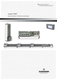
Front panel features on the <strong>SLX</strong>2020 chassis (Figure 1-1) include:<br />
❏ Reset switch (momentary)<br />
❏ Power switch<br />
❏ CD-ROM drive<br />
❏ 1.44 MB floppy disk drive<br />
CD-ROM Drive<br />
3.5 inch<br />
Floppy Drive<br />
Figure 1-1. Front Panel Features of the <strong>SLX</strong>2020<br />
2600 9908<br />
http://www.mcg.mot.com/literature 1-3<br />
1
1<br />
Introduction<br />
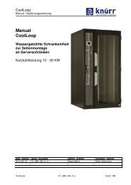
Rear Panel Features of the <strong>SLX</strong>2020<br />
Rear panel features on the <strong>SLX</strong>2020 chassis (Figure 1-2) include:<br />
❏ St<strong>and</strong>ard power connector<br />
❏ 2 USB ports<br />
❏ PS/2 Mouse port<br />
❏ Keyboard port<br />
❏ 2 COM ports<br />
❏ 10/100 Base Tx Ethernet port<br />
❏ Printer port<br />
❏ Video port<br />
❏ PCI expansion slot<br />
USB Ports Mouse Port COM2<br />
Printer Port<br />
Video Port<br />
Power Keyboard<br />
Connector<br />
Port<br />
COM1<br />
Ethernet<br />
Port<br />
Figure 1-2. Rear Panel Features on the <strong>SLX</strong>2020<br />
PCI Expansion<br />
Slot<br />
2599 990<br />
1-4 Computer Group Literature Center Web Site
Related Documentation<br />
Related Documentation<br />
The Motorola titles listed below are available in electronic format on the<br />
MCG literature page, at:<br />
http://www.mcg.mot.com/literature<br />
They can also be ordered by calling the Motorola Computer Group<br />
Literature Center at 888-432-1877 or at 602-804-7378.<br />
❏ PATX3000 ATX Motherboard BIOS <strong>and</strong> Programmer’s Reference<br />
Guide (PATX3BOSA/RM)<br />
❏ PATX3000 Pentium III ATX Motherboard <strong>Installation</strong> <strong>and</strong> <strong>Use</strong><br />
(PATX3A/IH)<br />
http://www.mcg.mot.com/literature 1-5<br />
1
1<br />
Introduction<br />
MCG Customer Services<br />
The Motorola Computer Group Customer Services organization provides<br />
numerous services that support the needs of our OEM customers<br />
throughout the qualification, development, deployment, <strong>and</strong> continued<br />
service phases of their product life cycles. Specific areas of support<br />
include:<br />
❏ Helping you identify <strong>and</strong> address your unique needs for providing<br />
outst<strong>and</strong>ing products to your customers<br />
❏ Extended warranties<br />
❏ 24 X 7 access to the high-level technical assistance that is crucial for<br />
mission critical applications around the world<br />
❏ 24 X 7 access to the latest technical information on MCG products,<br />
including known problems <strong>and</strong> a solutions database<br />
❏ Customized training available at the MCG campus or at any of your<br />
sites across the world<br />
❏ Customized documentation <strong>and</strong> 24 X 7 Internet access to product<br />
documentation<br />
❏ Services Central, a one-stop information source about customer<br />
services -- program content, pricing, <strong>and</strong> availability<br />
For information on what services are available, or to purchase a support<br />
contract, call us at Services Central, at 1-800-624-6745 or 602-438-5875,<br />
or visit our website at http://www.mcg.mot.com/support.<br />
1-6 Computer Group Literature Center Web Site
2<strong>Installation</strong> Instructions for <strong>SLX</strong><br />
<strong>Series</strong> Systems<br />
Receiving <strong>and</strong> Unpacking the System<br />
Note If the shipping cartons are damaged when received, request<br />
that the carrier’s agent be present during the unpacking <strong>and</strong><br />
inspection of the equipment.<br />
2<br />
You should receive a packing list, listing all the parts shipped with your<br />
system. Compare this packing list with the items you received. If it does<br />
not agree, immediately notify your carrier agent <strong>and</strong> Motorola. Any<br />
options ordered with the system are factory-installed <strong>and</strong> are not listed<br />
separately on the packing list. Save the shipping cartons for reuse.<br />
1. Make sure the packing carton is upright.<br />
2. Carefully cut the sealing tape with a box cutter <strong>and</strong> open the box.<br />
3. Remove the cardboard packing, any foam packing material <strong>and</strong><br />
protective plastic.<br />
4. Lift the chassis carefully out of the carton <strong>and</strong> move it to the location<br />
designated for the installation.<br />
2-1
2<br />
<strong>Installation</strong> Instructions for <strong>SLX</strong> <strong>Series</strong> Systems<br />
Guidelines for Locating the System<br />
❏ Locate the system in a stable area, free of excess movement <strong>and</strong><br />
jarring.<br />
❏ Install the system safely. Ensure cables <strong>and</strong> cords are out of the way.<br />
❏ Allow room for proper air flow for cooling. Allow at least three<br />
inches of space at the front <strong>and</strong> rear of the system.<br />
❏ Locate the system where it can be easily serviced. Service requires<br />
access to the front, rear, <strong>and</strong> top of the system.<br />
❏ Locate the system in an area free of heat, dust, smoke <strong>and</strong><br />
Electrostatic Discharge (ESD).<br />
Following ESD <strong>and</strong> Safety Procedures<br />
<strong>Use</strong> ESD<br />
Wrist Strap<br />
!<br />
Warning<br />
Motorola strongly recommends that you use an antistatic wrist strap <strong>and</strong> a<br />
conductive foam pad when installing or upgrading the system. Electronic<br />
components, such as disk drives, computer boards, <strong>and</strong> memory modules, can<br />
be extremely sensitive to ESD. After removing the component from the system<br />
or its protective wrapper, place the component flat on a grounded, static-free<br />
surface, <strong>and</strong> in the case of a board, component-side up. Do not slide the<br />
component over any surface.<br />
If an ESD station is not available, you can avoid damage resulting from ESD<br />
by wearing an antistatic wrist strap (available at electronics stores). Wrap one<br />
end of the wrist grounding strap around your wrist. Attach the grounding end<br />
(usually a piece of copper foil or an alligator clip) to an electrical ground. An<br />
electrical ground can be a piece of metal that runs into the ground (such as an<br />
unpainted metal pipe) or a metal part of a grounded electrical appliance. An<br />
appliance is grounded if it has a three-prong plug <strong>and</strong> is plugged into a threeprong<br />
grounded outlet. You cannot use the computer itself as a ground,<br />
because it is unplugged when you work on it.<br />
Turn system power off <strong>and</strong> unplug the system from its<br />
power source before you perform these procedures.<br />
Failure to turn the power off before opening the system can<br />
2-2 Computer Group Literature Center Web Site
Following ESD <strong>and</strong> Safety Procedures<br />
result in personal injury or equipment damage. Hazardous<br />
voltage, current <strong>and</strong> energy levels are present in this product.<br />
Power switch terminals can have hazardous voltages present<br />
even when the power switch is off. Do not operate the system<br />
with the covers removed. Always replace the covers before<br />
turning on the system.<br />
Grounding the <strong>SLX</strong>2020 System<br />
Mount the chassis with metal screws or bolts that give a good electrical<br />
connection between the screws or bolts <strong>and</strong> the mounting surface.<br />
Note Failure to observe proper grounding practices may cause a<br />
variety of noise, electrostatic discharge <strong>and</strong> RFI (Radio<br />
Frequency Interference) problems.<br />
http://www.mcg.mot.com/literature 2-3<br />
2
2<br />
<strong>Installation</strong> Instructions for <strong>SLX</strong> <strong>Series</strong> Systems<br />
Safety <strong>and</strong> Regulatory Compliance<br />
<strong>SLX</strong> <strong>Series</strong> systems comply with the safety <strong>and</strong> regulatory st<strong>and</strong>ards<br />
applicable to component-level equipment. It is possible, however, to use<br />
this product with other components that produce a system not in<br />
compliance with system guidelines. Since Motorola cannot anticipate what<br />
equipment may be used with this enclosure or how it may be used, the<br />
responsibility for designing a system that conforms overall to<br />
UL/CSA/VDE safety requirements <strong>and</strong> EMI/RFI emission limits rests<br />
entirely with the system integrator <strong>and</strong> installer.<br />
Regulatory Notes<br />
The <strong>SLX</strong>2020 has been evaulated to EN60950. The end user is to meet all<br />
EN60950 requirements when installing power supply into end use product.<br />
The <strong>SLX</strong>2020 is class 1 equipment.<br />
Lithium Battery Caution<br />
!<br />
Caution<br />
This system contains lithium batteries.<br />
Lithium batteries can explode if they are replaced incorrectly.<br />
Replace only with the same or equivalent type recommended<br />
by the equipment manufacturer. Dispose of used batteries<br />
according to the manufacturer’s instructions.<br />
2-4 Computer Group Literature Center Web Site
Environmental Considerations<br />
Environmental Considerations<br />
When installing the system in a particular environment, keep the<br />
environmental specifications of the system components in mind. For<br />
example, floppy <strong>and</strong> hard disk drives typically do not operate reliably<br />
above 50º C (122º F) ambient temperature. In an enclosed environment<br />
you need to consider the internal temperature rise over the worst case<br />
external ambient temperature. For this reason, the maximum operating<br />
temperature should not exceed 40º C.<br />
Cooling the Enclosure<br />
It is essential to properly cool all of the equipment used in a rack mounted<br />
system. The components of the system require an input air temperature<br />
below 50º C (122º F). Internal DC powered fans cool the system’s drives<br />
<strong>and</strong> modules. Natural convection cools the transition modules mounted in<br />
the back of the chassis. To ensure adequate cooling:<br />
❏ allow at least three inches of space at the front <strong>and</strong> back of the<br />
system.<br />
❏ make sure panels are in place, all front <strong>and</strong> back slots are filled <strong>and</strong><br />
all openings are covered.<br />
❏ cover all unused module slots.<br />
Power Circuit Loading Considerations<br />
Power for the rack system must come from totally dedicated circuit<br />
breakers. Do not plug any other electrical device into an outlet connected<br />
to the circuit breaker serving the rack equipment.<br />
Note Data loss can occur if the circuit is overloaded <strong>and</strong> the circuit<br />
breaker trips.<br />
http://www.mcg.mot.com/literature 2-5<br />
2
2<br />
<strong>Installation</strong> Instructions for <strong>SLX</strong> <strong>Series</strong> Systems<br />
Installing an <strong>SLX</strong> <strong>Series</strong> System in a 19-Inch<br />
Rack<br />
!<br />
Caution<br />
Do not mount the chassis at the top of the rack. A top-heavy<br />
rack can tip, causing damage to equipment <strong>and</strong> injury to<br />
personnel. See Figure 2-1.<br />
Two people should perform the following steps to avoid<br />
personal injury or damage to the equipment.<br />
1. Slide the <strong>SLX</strong> <strong>Series</strong> system into the front of the rack.<br />
2. Attach with four Phillips head screws.<br />
2-6 Computer Group Literature Center Web Site
Installing an <strong>SLX</strong> <strong>Series</strong> System in a 19-Inch Rack<br />
2601 9908<br />
Figure 2-1. Placing the <strong>SLX</strong>2020 in a Rack<br />
http://www.mcg.mot.com/literature 2-7<br />
2
2<br />
<strong>Installation</strong> Instructions for <strong>SLX</strong> <strong>Series</strong> Systems<br />
Connecting the System<br />
!<br />
Warning<br />
1. Plug the socket end of the chassis power cord packed with your<br />
system into the AC inlet on the rear of the chassis.<br />
2. If you are using a monitor:<br />
a. connect the socket end of the monitor’s power cord into the<br />
connector on the back of the monitor.<br />
b. Connect one end of the monitor (video) cable into the port on the<br />
monitor. (Not necessary if your monitor comes with the cable<br />
attached.)<br />
c. Plug the other end of the video cable into the 15-pin video<br />
connector on the rear of the system.<br />
3. If you are using a keyboard <strong>and</strong> mouse, connect the keyboard <strong>and</strong><br />
mouse cables into their ports on the rear of the system.<br />
4. Plug all power cords into a grounded, surge-protected power source.<br />
Disconnect the power cord before servicing the chassis to<br />
reduce the risk of electric shock or other possible hazards.<br />
Turning On the AC System<br />
Note Cover all open module slots <strong>and</strong> put all panels in place before<br />
turning on AC power. This is necessary to properly cool the<br />
chassis <strong>and</strong> to avoid electrical shock <strong>and</strong> other possible<br />
hazards. Slot covers <strong>and</strong> panels must remain in place during<br />
system operation.<br />
To turn on the AC system, press the power switch on the front of the<br />
chassis. The system begins its normal start-up routine <strong>and</strong> is ready to use.<br />
2-8 Computer Group Literature Center Web Site
Introduction<br />
3Upgrading Your System<br />
This chapter contains procedures for upgrading your system by:<br />
❏ Adding a PCI expansion card, see 3-2, <strong>and</strong><br />
❏ Adding additional memory, see 3-11.<br />
3<br />
3-1
3<br />
Upgrading Your System<br />
Installing a PCI Card<br />
<strong>SLX</strong>2020 systems ship from the MCG factory with one AGP graphics card<br />
<strong>and</strong> one PCI expansion slot. In order to install a PCI card, you should take<br />
the following steps:<br />
1. Remove the chassis cover, see 3-3.<br />
2. Remove the graphics card, see 3-4<br />
3. Remove the slot cover, see 3-5<br />
4. Insert the PCI card into the riser, see 3-6<br />
5. Install the PCI card <strong>and</strong> riser into the motherboard, see 3-8<br />
6. Reinstall the graphics card, see 3-9<br />
7. Reinstall the chassis cover, see 3-10<br />
3-2 Computer Group Literature Center Web Site
Removing the Chassis Cover<br />
Figure 3-1 shows how to remove the <strong>SLX</strong>2020 chassis cover.<br />
Figure 3-1. Removing the Chassis Cover<br />
Installing a PCI Card<br />
1. Remove the four phillips-head screws from the top of the cover.<br />
2. Push the cover back, <strong>and</strong><br />
3. Lift the cover off of the chassis.<br />
http://www.mcg.mot.com/literature 3-3<br />
3
3<br />
Upgrading Your System<br />
Removing the Graphics Card<br />
Figure 3-2 shows how to remove the graphics card from the <strong>SLX</strong>2020<br />
chassis.<br />
Figure 3-2. Removing the Graphics Card<br />
1. Remove the upper phillips-head screw from the side of the chassis.<br />
2. Disconnect the graphics card <strong>and</strong> riser from the motherboard by<br />
lifting directly up on the riser.<br />
3. Slide the card towards the chassis wall in order to remove the slot<br />
cover from the bracket, <strong>and</strong><br />
4. Remove the card.<br />
2594 9908<br />
3-4 Computer Group Literature Center Web Site
Removing the Expansion Slot Cover<br />
Figure 3-3 shows how to remove the expansion slot cover.<br />
Figure 3-3. Removing the Slot Cover<br />
Installing a PCI Card<br />
1. Remove the lower phillips-head screw from the side of the chassis.<br />
2. Remove the slot cover from the bracket by sliding it towards the<br />
chassis wall, <strong>and</strong><br />
3. Remove the slot cover.<br />
http://www.mcg.mot.com/literature 3-5<br />
3
3<br />
Upgrading Your System<br />
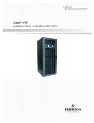
Inserting the PCI Card into the PCI Riser<br />
First, you should take the PCI riser that came with your system out of it’s<br />
protective packaging. Note that, as shown in, Figure 3-4, the PCI riser is<br />
shorter than the AGP riser that goes with your graphics card.<br />
AGP Riser<br />
PCI Riser<br />
3-6 Computer Group Literature Center Web Site
Figure 3-4. AGP <strong>and</strong> PCI Risers<br />
Installing a PCI Card<br />
Figure 3-5 shows how to, then, attach a PCI card to the PCI riser.<br />
Figure 3-5. Inserting the PCI Card into the PCI Riser<br />
1. Ensure that the card <strong>and</strong> riser are properly aligned.<br />
2. Slide the riser onto the PCI card.<br />
3. Ensure that the riser <strong>and</strong> PCI card are firmly connected.<br />
http://www.mcg.mot.com/literature 3-7<br />
3
3<br />
Upgrading Your System<br />
Installing the PCI Card <strong>and</strong> Riser into the <strong>SLX</strong>2020 Chassis<br />
Figure 3-6 shows how to install the PCI card <strong>and</strong> riser into the <strong>SLX</strong>2020<br />
chassis.<br />
Figure 3-6. Installing the PCI Card <strong>and</strong> Riser into the <strong>SLX</strong>2020 Chassis<br />
1. Insert the riser into the outer-most PCI slot on the motherboard.<br />
2. Insert the slot cover in the lower bracket.<br />
3. Ensure that the PCI slot-Riser connection is secure, <strong>and</strong><br />
4. Replace the lower phillips-head screw.<br />
3-8 Computer Group Literature Center Web Site
Reinstalling the Graphics Card<br />
Figure 3-7 shows how to reinstall the AGP graphics card.<br />
Figure 3-7. Reinstalling the Graphics Card<br />
1. Insert the riser into the graphics slot on the motherboard.<br />
2. Insert the slot cover in the upper bracket.<br />
3. Ensure that the AGP slot-Riser connection is secure, <strong>and</strong><br />
4. Replace the upper phillips-head screw.<br />
Installing a PCI Card<br />
http://www.mcg.mot.com/literature 3-9<br />
3
3<br />
Upgrading Your System<br />
Reinstalling the Chassis Cover<br />
Figure 3-8 shows how to replace the chassis cover once you are done<br />
adding the PCI card.<br />
Figure 3-8. Reinstalling the Chassis Cover<br />
1. Lower the cover onto the chassis.<br />
2. Slide the cover forward, <strong>and</strong><br />
3. Replace the four phillips-head screws.<br />
3-10 Computer Group Literature Center Web Site
Installing Additional Memory Modules<br />
Installing Additional Memory Modules<br />
The <strong>SLX</strong>2020 base system includes 128 MB of R<strong>and</strong>om Access memory.<br />
You can add up to three additional 128MB DIMMs by following these<br />
steps:<br />
1. Removing the chassis cover, see 3-12<br />
2. Installing the additional memory modules, see 3-13<br />
3. Replacing the chassis cover, see 3-14<br />
http://www.mcg.mot.com/literature 3-11<br />
3
3<br />
Upgrading Your System<br />
Removing the Chassis Cover<br />
Figure 3-9 shows how to remove the <strong>SLX</strong>2020 chassis cover.<br />
Figure 3-9. Removing the Chassis Cover<br />
1. Remove the four phillips-head screws from the top of the cover.<br />
2. Push the cover back, <strong>and</strong><br />
3. Lift the cover off of the chassis.<br />
3-12 Computer Group Literature Center Web Site
Installing Additional Memory Modules<br />
Installing Additional Memory Modules<br />
Figure 3-10 shows how to add additional memory modules.<br />
Figure 3-10. Installing Additional Memory Modules<br />
1. Open the clips on the side of the first vacant memory slot on the<br />
motherboard.<br />
2. Align the slots on the bottom of the memory module with the ridges<br />
in the expansion slot.<br />
3. Insert the memory module into the slot.<br />
4. Ensure that the module is securely connected to the motherboard,<br />
<strong>and</strong><br />
5. Fasten the clips on the side of the memory module.<br />
http://www.mcg.mot.com/literature 3-13<br />
3
3<br />
Upgrading Your System<br />
Reinstalling the Chassis Cover<br />
Figure 3-11 shows how to replace the chassis cover once you are done<br />
adding additional memory modules.<br />
Figure 3-11. Reinstalling the Chassis Cover<br />
1. Lower the cover onto the chassis.<br />
2. Slide the cover forward, <strong>and</strong><br />
3. Replace the four phillips-head screws.<br />
3-14 Computer Group Literature Center Web Site
ASystem Specifications<br />
Specifications for the <strong>SLX</strong>2020<br />
A<br />
This Appendix provides specifications on the <strong>SLX</strong>2020 system as well as<br />
providing recommended environmental specifications. It contains the<br />
following sections:<br />
❏ Chassis Specifications on page A-2<br />
❏ Environmental <strong>and</strong> Regulatory Specifications on page A-4<br />
A-1
A<br />
Chassis Specifications<br />
Chassis Specifications<br />
A-2<br />
The <strong>SLX</strong>2020 chassis is a 2U chassis that is suitable for mounting in a<br />
st<strong>and</strong>ard 19-inch rack. The chassis dimensions, as shown in Figure A-1,<br />
are:<br />
❏ 3.5 inches high<br />
❏ 17 inches wide<br />
❏ 18.75 inches deep<br />
17 ”<br />
Figure A-1. <strong>SLX</strong>2020 chassis dimensions.<br />
3.5 ’’<br />
18.75 ”
Table A-1 contains specifications for the <strong>SLX</strong>2020 chassis.<br />
Table A-1. Specifications for the <strong>SLX</strong>2020 Chassis<br />
Specifications Description<br />
Chassis Dimensions 17 inches wide<br />
3.5 inches high<br />
18.75 inches deep<br />
Weight Approximately 25 pounds.<br />
Power Supply 145 Watts<br />
Voltage: AC 100-120/200-240V<br />
Frequency: 60/50 Hz<br />
Current: 2.0/1.0A<br />
System Specifications<br />
A-3<br />
A
A<br />
Environmental <strong>and</strong> Regulatory Specifications<br />
Environmental <strong>and</strong> Regulatory Specifications<br />
A-4<br />
An <strong>SLX</strong>2020 system requires minimum maintenance <strong>and</strong> care to keep it<br />
operating properly. A proper environment for the system means placing<br />
the unit within the appropriate temperature, humidity <strong>and</strong> altitude ranges.<br />
For the best system performance keep environmental parameters as close<br />
as possible to the middle of these environmental ranges. Environmental<br />
conditions should not change abruptly.<br />
Table A-2 contains recommended environmental specifications for the<br />
<strong>SLX</strong>2020.<br />
Table A-2. Environmental <strong>and</strong> Regulatorty Specifications for the <strong>SLX</strong>2020<br />
Specifications Description<br />
Environmental Temperature: +5º C to +40º C (operating)<br />
-20º C to +70º C (storage)<br />
Humidity: 5% to 95% @40º C (operating)<br />
0% to 95% @ 40º C (storage)<br />
Altitude: 6000 feet (1829 m) (operating) / 50,000 feet (15,240<br />
m) (storage)<br />
Shock: 10G @ 10ms duration (operating) 40G @ 10ms<br />
duration (storage)<br />
Vibration: 1.5G @ 5 to 150Hz (operating) / 5G @ 5 to 150Hz<br />
(storage)<br />
Static Discharge: IEC 801-2 Level 3 (8KV)<br />
Acoustic Noise: >54 dBA (peripherals idle, at 1 m)<br />
Regulatory Conformance Safety: UL1950, 2nd edition; CUL; VDE<br />
Flammability: Backplane material FR-4, UL 94V-1<br />
EMI/RFI: FCC Class A; CE Mark to CISPR 22 for Class A<br />
ESD: Per IEC 801-2/3/4/5, Level 3
B<strong>Installation</strong>sanweisung für<br />
Systeme der Serie <strong>SLX</strong><br />
Empfangen und Auspacken des Systems<br />
Hinweis Falls die Vers<strong>and</strong>kartons bei Empfang beschädigt sind,<br />
sollten Sie den Lieferungsagenten bitten, bei dem<br />
Auspacken und der Inspektion des Gerätes anwesend zu<br />
sein.<br />
B<br />
Dem Gerät sollte eine Teileliste beiliegen, die alle im Lieferumfang des<br />
Systems enthaltenen Teile auflistet. Vergleichen Sie diese Teileliste mit<br />
den erhaltenen Teilen. Sollte die Teileliste nicht mit den erhaltenen Teilen<br />
übereinstimmen, benachrichtigen Sie unverzüglich den Lieferungsagenten<br />
und Motorola. Alle mit dem System bestellten Optionen sind werkseitig<br />
installiert und werden nicht separat auf der Teileliste aufgelistet. Bewahren<br />
Sie die Vers<strong>and</strong>kartons auf, um sie ggf. wiederverwenden zu können.<br />
1. Stellen Sie sicher, daß sich der Verpackungskarton in aufrechter<br />
Position befindet.<br />
2. Schneiden Sie das Verpackungsklebeb<strong>and</strong> vorsichtig mit einem<br />
Kartonschneider auf, und öffnen Sie dann den Karton.<br />
3. Entfernen Sie die Kartonverpackung, das<br />
Schaumstoffverpackungsmaterial und die schützende<br />
Plastikverpackung.<br />
4. Heben Sie das Chassis vorsichtig aus dem Karton, und plazieren Sie<br />
es an dem gewünschten Aufstellungsort.<br />
Richtlinien zum Aufstellen des Systems<br />
❏ Stellen Sie das System in einem Bereich auf, der frei von<br />
übermäßigen Bewegungen und Erschütterungen ist.<br />
B-1
B<br />
ESE- und Sicherheitsmaßnahmen<br />
B-2<br />
❏ Installieren Sie das System im Hinblick auf Sicherheit. Stellen Sie<br />
sicher, daß Kabel und Drähte den Zugang nicht behindern.<br />
❏ Lassen Sie Platz für eine ausreichende Luftzirkulation zur Kühlung.<br />
Stellen Sie sicher, daß vor und hinter dem System mindestens 10 cm<br />
Freiraum gelassen wird.<br />
❏ Stellen Sie das System so auf, daß es problemlos gewartet werden<br />
kann. Bei Wartungsarbeiten ist Zugang zur Vorder- und Rückseite<br />
des Systems erforderlich.<br />
❏ Stellen Sie das System in einem Bereich auf, an dem es nicht Hitze,<br />
Staub, Rauch und elektrostatischer Entladung (ESE) ausgesetzt ist.<br />
ESE- und Sicherheitsmaßnahmen<br />
ESE-Anti-<br />
statikb<strong>and</strong><br />
verwenden<br />
Motorola empfiehlt, bei den <strong>Installation</strong>s- oder Aufrüstarbeiten am System<br />
ein Antistatikb<strong>and</strong> und eine ableitende Schaumstoffunterlage zu<br />
verwenden. Elektronische Komponenten, wie z.B. Plattenlaufwerke,<br />
Platinen und Speichermodule, können gegen ESE äußerst empfindlich<br />
sein. Nach dem Entfernen eines Bauteils aus dem System oder aus der<br />
Schutzhülle wird das Bauteil flach auf eine geerdete und statikfreie<br />
Oberfläche gelegt, und im Falle einer Platine mit der Komponentenseite<br />
nach oben. Das Bauteil nicht auf der Oberfläche hin und her bewegen.<br />
Wenn kein ESE-Arbeitsplatz verfügbar ist, können ESE-Gefahren durch<br />
das Tragen eines Antistatikb<strong>and</strong>s vermieden werden (erhältlich in<br />
Elektronik-Fachgeschäften). Dabei ist ein Ende des B<strong>and</strong>es um das<br />
H<strong>and</strong>gelenk zu legen. Das Erdungsende (normalerweise ein Stück<br />
Kupferfolie oder eine Krokodilklemme) an einer elektrischen<br />
Masseverbindung anschließen. Hierbei kann es sich um ein Stück Metall<br />
h<strong>and</strong>eln, daß direkt zur Erde führt (z.B. ein unbeschichtetes Metallrohr)<br />
oder ein Metallteil eines geerdeten, elektrischen Gerätes. Ein elektrisches<br />
Gerät ist geerdet, wenn es einen dreistiftigen Schukostecker besitzt, der in<br />
eine Schuko-Steckdose gesteckt wird. Das System selbst kann nicht als<br />
Masseverbindung verwendet werden, weil es bei allen Arbeiten vom Netz<br />
getrennt wird.
!<br />
Warnung<br />
<strong>Installation</strong>sanweisung für Systeme der Serie <strong>SLX</strong><br />
Vor dem Ausführen dieser Verfahren ist die Stromzufuhr<br />
des Systems auszuschalten und das System vom Stromnetz<br />
zu trennen. Wenn der Strom vor dem Öffnen des Systems<br />
nicht ausgeschaltet wird, besteht die Gefahr von<br />
Körperverletzungen und Beschädigungen des Gerätes. Im<br />
Gerät sind gefährliche Spannungen, Strom und Hochenergie<br />
vorh<strong>and</strong>en. An den Anschlußpunkten der Betriebsschalter<br />
können gefährliche Spannungen anliegen, auch wenn sich der<br />
Schalter in der ausgeschalteten Position befindet. Das System<br />
darf nicht bei abgenommener Gehäuseabdeckung betrieben<br />
werden. Vor dem Einschalten des Systems ist die<br />
Gehäuseabdeckung stets anzubringen.<br />
Sicherheit und Approbationen<br />
Die Systeme Serie <strong>SLX</strong> entsprechen allen Sicherheits- bzw. EMI-<br />
Bestimmungen, die auf einzelne Geräteteile zutreffen. Es ist jedoch<br />
möglich, dieses Produkt mit <strong>and</strong>eren Einzelteilen zusammen zu<br />
verwenden, die ein System ergeben, das den Systemrichtlinien nicht<br />
entspricht. Da Motorola nicht voraussehen kann, welche Geräte auf<br />
welche Weise mit diesem Gehäuse verwendet werden, ist der<br />
Systemintegrator und Installateur völlig dafür verantwortlich, daß das<br />
gesamte fertiggestellte System den Sicherheitsanforderungen von<br />
UL/CSA/VDE sowie den EMI/HFI-Emissionsgrenzen entspricht.<br />
Vorsichtshinweis zur Lithium-Batterie<br />
!<br />
Vorsicht<br />
Dieses System enthält Lithium-Batterien.<br />
Bei einem unsachgemäßen Austausch der Lithium-Batterien<br />
besteht Explosionsgefahr. Ersetzen Sie die Batterien nur<br />
durch denselben oder einem vom Herstellen empfohlenen<br />
gleichwertigen Batterietyp. Entsorgen Sie gebrauchte<br />
Batterien gemäß den Anweisungen des Herstellers.<br />
B-3<br />
B
B<br />
Berücksichtigungen bei Wahl der Betriebsumgebung<br />
Berücksichtigungen bei Wahl der<br />
Betriebsumgebung<br />
B-4<br />
Bei der <strong>Installation</strong> des Systems in einer bestimmten Betriebsumgebung<br />
sollten die technischen Daten zur Betriebsumgebung der<br />
Systemkomponenten beachtet werden. Zum Beispiel: Der Betrieb von<br />
Disketten- und Festplattenlaufwerken ist bei Umgebungstemperaturen<br />
über 50º C (122º F) nicht mehr zuverlässig. Bei einem Gerät, das in einem<br />
Gehäuse installiert ist, sollten Sie beachten, daß die interne<br />
Umgebungstemperatur über die maximal mögliche, externe<br />
Umgebungstemperatur ansteigen kann. Die maximale<br />
Umgebungstemperatur betraegt 40º C.<br />
Kühlen des Gehäuses<br />
Es ist äußerst wichtig, daß alle Geräte eines Rack-Systems auf angemessene<br />
Weise gekühlt werden. Die Eingangslufttemperatur der Systemkomponenten<br />
muß unter 50º C (122º F) liegen. Interne durch Gleichstrom<br />
betriebene Ventilatoren kühlen die Laufwerke und Module des Systems.<br />
Die Übergangsmodule an der Rückseite des Chassis werden durch natürliche<br />
Konvektion gekühlt. Um eine ausreichende Kühlung zu gewährleisten,<br />
sollten Sie:<br />
❏ Dafür sorgen, daß vor und hinter dem System mindestens 10 cm<br />
Freiraum gelassen wird.<br />
❏ Sicherstellen, daß alle Verkleidungen aufgesetzt, alle Modulschlitze<br />
vorn und hinten gefüllt und alle sonstigen Einbauöffnungen<br />
abgedeckt sind.<br />
Berücksichtigungen zur Stromkreisbelastung<br />
Das Rack-System muß von einem völlig dedizierten Stromunterbrecher<br />
mit Netzstrom versorgt werden. Schließen Sie kein <strong>and</strong>eres elektrisches<br />
Gerät an eine Steckdose an, die mit dem Stromunterbrecher verbunden ist,<br />
der das Rack-Gerät mit Strom versorgt.
<strong>Installation</strong>sanweisung für Systeme der Serie <strong>SLX</strong><br />
Hinweis Wenn der Stromkreis überlastet wird und der<br />
Stromunterbrecher kippt, besteht die Gefahr von<br />
Datenverlust.<br />
Einbau eines <strong>SLX</strong>-Serie-Systems in ein 19-Zoll-<br />
Rack<br />
!<br />
Vorsicht<br />
Installieren Sie das Chassis nicht oben am Rack. Ein<br />
kopflastiges Rack kann Umkippen und Geräte beschädigen<br />
oder Personal verletzen.<br />
Die folgenden Schritte sollten von zwei Personen ausgeführt<br />
werden, um Verletzungen von Personen bzw.<br />
Beschädigungen der Geräte zu vermeiden.<br />
1. Schieben Sie das System Serie <strong>SLX</strong> vorne in das Rack.<br />
2. Befestigen Sie das Chassis mit vier Kreuzschlitzschrauben.<br />
Anschließen des Systems<br />
1. Stellen Sie sicher, daß der Netzschalter (EIN/AUS) an der<br />
Vorderseite des Chassis auf AUS (O) gesetzt ist.<br />
2. Stecken Sie das Sockelende des im Lieferumfang des Systems<br />
enthaltenen Chassisnetzkabels in die Netzsteckbuchse an der<br />
Rückseite des Chassis.<br />
3. Stecken Sie das Sockelende des Monitornetzkabels in die<br />
Anschlußbuchse an der Rückseite des Monitors.<br />
4. Stecken Sie ein Ende des Videokabels in die Anschlußbuchse des<br />
Monitors. (Dies ist nicht erforderlich, wenn das Videokabel des<br />
Monitors permanent am Monitor befestigt ist.)<br />
B-5<br />
B
B<br />
Einschalten des Netzstroms<br />
B-6<br />
5. Stecken Sie das <strong>and</strong>ere Ende des Videokabels in die 15polige<br />
Videoanschlußbuchse an der Rückseite des Chassis.<br />
6. Stecken Sie die Tastatur- und Mauskabel in die entsprechenden<br />
Anschlußbuchsen an der Rückseite des Chassis.<br />
7. Stecken Sie alle Netzkabel in eine geerdete, gegen<br />
Spannungsspitzen geschützte Schuko-Steckdose.<br />
!<br />
Warnung<br />
Vor Wartungsarbeiten am Chassis ist das Netzkabel vom Stromnetz zu trennen, um die<br />
Gefahr eines elektrischen Schlages oder <strong>and</strong>ere mögliche Gefahren zu reduzieren.<br />
Einschalten des Netzstroms<br />
Hinweis Decken Sie alle offenen Modulschlitze ab, und setzen Sie<br />
alle Verkleidungen auf, bevor Sie den Netzstrom<br />
einschalten. Diese Maßnahmen sind notwendig, sowohl<br />
um eine angemessene Kühlung des Chassis zu sichern als<br />
auch um das Risiko eines elektrischen Schlages und <strong>and</strong>ere<br />
mögliche Gefahren zu vermeiden. Für die Dauer des<br />
Systembetriebs müssen die Schlitzabdeckungen und<br />
Verkleidungen am Chassis bleiben.<br />
Um den Netzstrom einzuschalten, bewegen Sie den Kippschalter in die<br />
Position EIN (I). Die normale Startroutine des Systems erfolt, und das<br />
System ist dann einsatzbereit.
Anmerkungen<br />
<strong>Installation</strong>sanweisung für Systeme der Serie <strong>SLX</strong><br />
Das <strong>Network</strong> server ist ein Geraet der Schutzklasse 1.<br />
Das Gerätl ist nur zum Einbau fuer EN 60950 Geraete.<br />
Bein Aufstellen des Gerätes ist daraf zu achten das alle Andforderungen<br />
gemäß EN60950 eingehalten werden.<br />
B-7<br />
B
B<br />
Anmerkungen<br />
B-8