MODEL 300MB-SD - Federal Signal
MODEL 300MB-SD - Federal Signal
MODEL 300MB-SD - Federal Signal

Create successful ePaper yourself
Turn your PDF publications into a flip-book with our unique Google optimized e-Paper software.
GND<br />
enable and signal in terminals. The SIG COM terminals<br />
(TB1-16) of both uinits also need to be connected<br />
together as shown in figure 3-2.<br />
3-7. SIGNAL LINES.<br />
120/240 VAC<br />
CLASS I FIELD WIRING<br />
COMPARTMENT<br />
NOT USED<br />
NOT USED<br />
The signal lines transfer the messages from a<br />
CommCenter to the remote SelecTone devices. In<br />
order to reduce the possibility of cross talk, hum, and<br />
static noise pick-up, the signal lines must be twisted<br />
pair audio cable. In the majority of systems, use<br />
AWG 18 twisted pair audio cables. Shielded, twisted<br />
pair cable is recommended when the Class II signal<br />
circuit is in the vicinity of welding equipment, carbon<br />
arc equipment, or similar electrical devices. Never<br />
use a cable having wire smaller than AWG 22.<br />
<strong>Federal</strong> <strong>Signal</strong> Corporation does not recommend<br />
that new or existing telephone lines be<br />
used as signal lines in a SelecTone system for<br />
the following reasons:<br />
1. Interference from other services or<br />
systems, or interference from the<br />
system to other services.<br />
2. Cross talk, interference, or hum<br />
induced by other telephone lines.<br />
+ 24VDC<br />
- 24VDC<br />
POWER DOWN<br />
3. Extended downtime because of the<br />
second party involvement required to<br />
service the lines.<br />
POWER<br />
MONITOR<br />
RELAY<br />
NO<br />
NC<br />
COM<br />
KNOCK-OUTS IN REAR OF HOUSING<br />
CASCADE<br />
IN<br />
ENABLE<br />
SIGNAL<br />
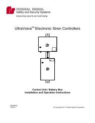
Figure 3-1. Model <strong>300MB</strong> Rear View.<br />
3-3<br />
OUTPUT LEVEL<br />
MIC OUT<br />
SIG COM<br />
SIG HI<br />
SIG<br />
25 VRMS<br />
LINE<br />
SIG<br />
CASCADE<br />
OUT<br />
SIGNAL<br />
ENABLE<br />
PTT<br />
RELAY<br />
COM<br />
NC<br />
NO<br />
COM<br />
MESSAGE 1<br />
MESSAGE 2<br />
MESSAGE 3<br />
MESSAGE 4<br />
MESSAGE 5<br />
MESSAGE 6<br />
TB2 TB1<br />
10 9 8 7 6 5 4 3 2 1 17 16 15 14 13 12 11 10 9 8 7 6 5 4 3 2 1<br />
<strong>MODEL</strong> <strong>300MB</strong> REAR VIEW<br />
(BACK OF HOUSING IS REMOVED FOR CLARITY)<br />
CLASS II FIELD WIRING<br />
COMPARTMENT<br />
290A2923<br />
4. The additional cost of installation,<br />
interfacing devices and monthly<br />
charges as opposed to a one-time cost<br />
of performing the installation.<br />
3-8. <strong>MODEL</strong> <strong>300MB</strong> SIGNAL CONNECTIONS.<br />
Mixing signal lines with power lines could<br />
cause electrical interference, which could<br />
impede or render the system inoperable. Do<br />
not install signal lines in the same conduit<br />
with power lines.<br />
To connect the signal lines of the SelecTone system<br />
to the <strong>300MB</strong>, connect a color coded twisted pair<br />
of audio cables having conductors no smaller than 18<br />
AWG to SIG HI (TB1-15) and SIG COM (TB1-16) terminals<br />
on TB1 (see figure 3-1). Every remote Selec-<br />
Tone signaling device in the system will be connected<br />
in parallel to these lines. When connecting the remote<br />
devices in parallel to the signal lines, observe the<br />
correct polarity and install wire nuts over the connections.<br />
The yellow wires on the 300CK should be<br />
connected to the SIG HI while the blue wires should<br />
be connected to SIG COM.<br />
The 25Vrms speaker output is available at<br />
TB1-13 and TB1-14 for direct connection to ceiling<br />
speakers (see figure 3-1). Remove the labeled jumper<br />
from terminals TB1-13 and TB1-14 of terminal block<br />
TB1, before using these positions. <strong>Signal</strong> line losses