WARNING!
WARNING!
WARNING!

Create successful ePaper yourself
Turn your PDF publications into a flip-book with our unique Google optimized e-Paper software.
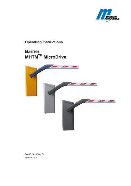
Operating Instructions<br />
Barrier<br />
MHTM TM MicroDrive<br />
Doc-ID: 5815,5001EN<br />
Version: 02.6
Translation of the Original Operating Instructions<br />
MAGNETIC Autocontrol GmbH<br />
Grienmatt 20<br />
79650 Schopfheim<br />
Germany<br />
Tel.: +49 (0)7622 695 5<br />
Fax.: +49 (0)7622 695 602<br />
E-Mail: info@ac-magnetic.com<br />
Internet: www.ac-magnetic.com<br />
2 5815,5001EN / Version 02.6
Contents<br />
Barrier MHTM TM MicroDrive<br />
Contents<br />
1 General..................................................................................10<br />
1.1 Information regarding the operating instructions .........10<br />
1.2 Pictogram explanation .................................................11<br />
1.3 Limitation of liability......................................................12<br />
1.4 Copyright protection.....................................................12<br />
1.5 Scope of delivery .........................................................13<br />
1.6 Warranty ......................................................................13<br />
1.7 Disclaimer ....................................................................13<br />
1.8 Customer service.........................................................13<br />
1.9 EC-Declarations of conformity.....................................14<br />
1.10 Environmental protection .............................................14<br />
2 Safety ....................................................................................15<br />
2.1 Intended use of the barriers.........................................15<br />
2.1.1 Intended use for certain road vehicles .........15<br />
2.1.2 Barrier, pedestrian traffic impossible............15<br />
2.1.3 Barrier, pedestrian traffic not impossible......16<br />
2.1.4 Non-intended use .........................................16<br />
2.2 Operator's responsibility ..............................................17<br />
2.3 Changes and modifications .........................................17<br />
2.4 Specialists and operating personnel............................18<br />
2.4.1 Requirements ...............................................18<br />
2.5 Personal protective equipment ....................................19<br />
2.6 Occupational safety and special dangers....................19<br />
2.6.1 Danger symbols on the<br />
MHTM TM MicroDrive barrier..........................19<br />
2.6.2 Hazard notes and occupational safety .........20<br />
2.7 Danger area.................................................................27<br />
3 Identification.........................................................................28<br />
3.1 Type plate ....................................................................28<br />
3.2 Type code ....................................................................29<br />
4 Technical data ......................................................................30<br />
4.1 Access .........................................................................30<br />
4.1.1 Dimensions and weight ................................30<br />
4.1.2 Electrical connection ....................................31<br />
4.1.3 Operating conditions ....................................31<br />
4.1.4 Operating times ............................................31<br />
5815,5001EN / Version 02.6 3
Barrier MHTM TM MicroDrive<br />
Contents<br />
4.2 Access Pro H .............................................................. 32<br />
4.2.1 Dimensions and weight ............................... 32<br />
4.2.2 Electrical connection.................................... 33<br />
4.2.3 Operating conditions.................................... 33<br />
4.2.4 Operating times ........................................... 33<br />
4.3 Parking ........................................................................ 34<br />
4.3.1 Dimensions and weight ............................... 34<br />
4.3.2 Electrical connection.................................... 35<br />
4.3.3 Operating conditions.................................... 35<br />
4.3.4 Operating times ........................................... 35<br />
4.4 Toll............................................................................... 36<br />
4.4.1 Dimensions and weight ............................... 36<br />
4.4.2 Electrical connection.................................... 37<br />
4.4.3 Operating conditions.................................... 37<br />
4.4.4 Operating times ........................................... 37<br />
4.5 Control unit.................................................................. 38<br />
4.6 Plug-in module "Detector A–B" ................................... 39<br />
4.7 Plug-in module "Radio" ............................................... 39<br />
5 Design and function............................................................ 40<br />
5.1 Design ......................................................................... 40<br />
5.1.1 Access and Parking..................................... 40<br />
5.1.2 Access Pro H ............................................... 41<br />
5.1.3 Toll ............................................................... 42<br />
5.2 Function ...................................................................... 43<br />
6 Transport and storage ........................................................ 44<br />
6.1 Safety notes for transport............................................ 44<br />
6.2 Transport inspection.................................................... 45<br />
6.3 Transport..................................................................... 46<br />
6.4 Storage........................................................................ 46<br />
7 Design notes for induction loops ...................................... 47<br />
8 Assembly and installation.................................................. 51<br />
8.1 Safety .......................................................................... 51<br />
8.2 Required steps ............................................................ 52<br />
8.3 Foundation and empty conduits.................................. 53<br />
8.3.1 Foundation and empty conduits<br />
for the barrier ............................................... 54<br />
8.3.2 Foundation and empty conduits for<br />
nesting post or light barrier post .................. 57<br />
8.4 Assembly and installation of induction loops .............. 59<br />
8.4.1 Directions for the assembly and<br />
installation of induction loops....................... 59<br />
8.4.2 Induction loops............................................. 61<br />
8.4.3 Testing induction loops................................ 61<br />
4 5815,5001EN / Version 02.6
Barrier MHTM TM MicroDrive<br />
Contents<br />
8.4.4 Installing induction loops in bitumen,<br />
asphalt, or concrete......................................61<br />
8.4.5 Installing induction loops under<br />
interlocking stone paving..............................63<br />
8.5 Unpacking....................................................................64<br />
8.6 Assemble housing .......................................................64<br />
8.7 Assemble nesting post or light barrier post .................66<br />
8.8 Assemble safety light barrier .......................................67<br />
8.8.1 Assemble transmitter....................................67<br />
8.8.2 Assemble receiver........................................68<br />
8.9 Assemble barrier boom type "VarioBoom" ..................69<br />
8.10 Assemble edge protection ...........................................69<br />
8.11 Assembling flange and barrier boom...........................70<br />
8.11.1 Barrier boom type "VarioBoom" and<br />
"MicroBoom".................................................70<br />
8.11.2 Barrier boom type "MicroBoom-T"................73<br />
8.12 Conversion "left version" – "right version"<br />
(VarioBoom and MicroBoom) ......................................76<br />
8.13 Check and set the balancing springs in the<br />
lever system.................................................................80<br />
8.13.1 Setting balancing springs .............................81<br />
8.13.2 Overview table balancing springs ................82<br />
8.14 Align barrier housing and post.....................................84<br />
8.15 Set nesting post height ................................................85<br />
8.16 Stick on prohibition signs .............................................86<br />
8.17 Check assembly and installation .................................86<br />
9 Electrical connection...........................................................87<br />
9.1 Safety...........................................................................87<br />
9.2 Installing electrical protective devices .........................88<br />
9.3 Connecting the power cable ........................................89<br />
9.4 Connect customer's control lines (signalling devices) .91<br />
9.4.1 Connecting safety devices ...........................92<br />
9.4.2 Plausibility check of the safety devices ........92<br />
9.4.3 Connecting safety loop.................................93<br />
9.4.4 Connect and test the safety light barriers.....94<br />
9.4.5 Connecting emergency opening contacts ....94<br />
9.4.6 Digital inputs.................................................95<br />
9.4.7 Digital outputs and output relays..................97<br />
9.5 Checking the electrical connection ............................102<br />
10 Parameterising control unit ..............................................103<br />
10.1 Safety ....................................................................103<br />
10.2 Control elements control unit.....................................103<br />
10.3 Displays on the control unit........................................104<br />
5815,5001EN / Version 02.6 5
Barrier MHTM TM MicroDrive<br />
Contents<br />
10.4 Symbols in the display .............................................. 105<br />
10.4.1 Control button functions............................. 105<br />
10.4.2 Current state of the barrier ........................ 106<br />
10.4.3 Current programme mode ......................... 107<br />
10.4.4 Current state of the induction loops........... 107<br />
10.4.5 Further symbols......................................... 107<br />
10.5 Parameterising options ............................................. 108<br />
10.6 Parameterising values............................................... 109<br />
10.7 Select programme mode........................................... 110<br />
10.7.1 Mode 1: Maintained contact ...................... 111<br />
10.7.2 Mode 2: Deadman ..................................... 112<br />
10.7.3 Mode 3: Pulse control (bistable) ................ 113<br />
10.7.4 Mode 4: Two-pulse control ........................ 114<br />
10.7.5 Automatic Modes 5 to 8:<br />
Drive direction 1 –<br />
overview and differences........................... 115<br />
10.7.6 Automatic Modes 5 to 8:<br />
Drive direction 2......................................... 119<br />
10.7.7 Mode "Service" .......................................... 120<br />
10.8 Menu "Information" ( ) .............................................. 121<br />
10.9 Programme mode ..................................................... 121<br />
10.10 Menu "Setup" ............................................................ 122<br />
10.10.1 Barrier speed ............................................. 122<br />
10.10.2 Delays........................................................ 122<br />
10.10.3 Cut off angle .............................................. 124<br />
10.10.4 Inputs ......................................................... 124<br />
10.10.5 Outputs ...................................................... 124<br />
10.10.6 Vend count................................................. 125<br />
10.10.7 Impact settings........................................... 128<br />
10.10.8 Start-up behaviour ..................................... 129<br />
10.10.9 Power failure.............................................. 133<br />
10.10.10 Closure by light barrier .............................. 134<br />
10.10.11 Master/Slave.............................................. 134<br />
10.10.12 Menu "Language" ...................................... 135<br />
10.11 Menu "Attachments".................................................. 135<br />
10.11.1 Signal light ................................................. 135<br />
10.11.2 Boom contact settings ............................... 138<br />
10.11.3 Boom locking ............................................. 139<br />
10.12 Menu "Service".......................................................... 140<br />
10.13 Menu "Information".................................................... 140<br />
10.14 Menu "Motor GW (Gateway)..................................... 140<br />
6 5815,5001EN / Version 02.6
Barrier MHTM TM MicroDrive<br />
Contents<br />
10.15 Menu "Detector 1 (A-B)" ............................................141<br />
10.15.1 Check the working frequency of<br />
the induction loops .....................................142<br />
10.15.2 Reconciling and setting the operating<br />
frequency of the induction loop ..................143<br />
10.16 Menu "Detector 2 (C-D)"............................................145<br />
10.17 Menu "Radio control FM"...........................................145<br />
10.18 Factory settings..........................................................148<br />
11 Start-up and operation ......................................................149<br />
11.1 Safety ....................................................................149<br />
11.2 Commissioning ..........................................................150<br />
11.3 Switching on and off the barrier.................................150<br />
11.4 Putting the barrier temporarily out of operation .........151<br />
12 Maintenance .......................................................................153<br />
12.1 Safety ....................................................................153<br />
12.2 Cleaning ....................................................................154<br />
12.3 Maintenance schedule...............................................155<br />
13 Malfunctions .......................................................................157<br />
13.1 Safety ....................................................................157<br />
13.2 Malfunction table – barrier malfunctions....................158<br />
13.3 Warning and interference messages on<br />
the display..................................................................161<br />
13.3.1 Warning and interference messages –<br />
Logic control (control unit) ..........................161<br />
13.3.2 Warning and interference messages –<br />
Motor GW ...................................................163<br />
13.3.3 Warning and interference messages –<br />
detector.......................................................164<br />
13.3.4 Warning and interference messages –<br />
All modules.................................................165<br />
13.4 Reset the barrier ........................................................165<br />
13.5 Closing or opening the barrier boom in case<br />
of power failure ..........................................................166<br />
14 Repair ..................................................................................167<br />
14.1 Safety ....................................................................167<br />
14.2 Spare parts ................................................................168<br />
14.3 Replacing the barrier boom .......................................168<br />
14.3.1 Barrier boom type "VarioBoom" and<br />
"MicroBoom"...............................................168<br />
14.3.2 Barrier boom type "MicroBoom-T"..............172<br />
5815,5001EN / Version 02.6 7
Barrier MHTM TM MicroDrive<br />
Contents<br />
15 Decommissioning, disassembly and disposal............... 174<br />
16 EC-Declarations of conformity ........................................ 175<br />
16.1 Barrier, pedestrian traffic impossible......................... 175<br />
16.2 Barrier, pedestrian traffic not impossible................... 177<br />
17 Appendix ............................................................................ 179<br />
17.1 Wiring diagram .......................................................... 179<br />
17.2 Menu setup ............................................................... 187<br />
Index........................................................................................... 191<br />
8 5815,5001EN / Version 02.6
Barrier MHTM TM MicroDrive<br />
General<br />
5815,5001EN / Version 02.6 9
Barrier MHTM TM MicroDrive<br />
General<br />
1 General<br />
1.1 Information regarding the operating instructions<br />
Programme versions<br />
Control unit MGC and<br />
plug modules<br />
These operating instructions provide crucial information on handling<br />
of MAGNETIC barriers MHTM TM MicroDrive. Pre-requisite for<br />
safe working is the observance of all specified safety notes and instructions.<br />
In addition, the local accident prevention regulations valid at the<br />
barrier's area of application and general safety regulations have to<br />
be complied with.<br />
Carefully read the operating instructions before starting any work!<br />
They are a product component and must be kept in direct proximity<br />
of the barrier, well accessible to the personnel at all times.<br />
When passing the barrier on to third parties, the operating instructions<br />
must also be handed over.<br />
Components from other suppliers may have their own safety regulations<br />
and instructions for use. These must also be observed.<br />
This operating instruction is valid for the following programme<br />
versions. Software number (software #) and software version<br />
(SW version) are indicated in the respective menu "Information" or<br />
"Motor GW".<br />
Designation Software # SW version<br />
Master Controller Standard 4915,1000 0.7<br />
Motor Gateway Controller 4915,3000 0.6<br />
Detector module 2-channel 4915,3001 0.6<br />
Radio module 433 MHz 4915,3003 0.4<br />
Ethernet Module 4915,3004 0.1<br />
Table 1: Programme versions<br />
10 5815,5001EN / Version 02.6
1.2 Pictogram explanation<br />
Barrier MHTM TM MicroDrive<br />
General<br />
Warning notes Warning notes are characterised by pictograms in these operating<br />
instructions. The warning notes are prelude by signal words expressing<br />
the scale of the hazard.<br />
It is absolutely essential to observe the notes and to proceed with<br />
caution in order to prevent accidents as well as bodily injuries and<br />
property damage.<br />
Hints and recommendations<br />
DANGER!<br />
DANGER!<br />
… points to an immediately dangerous situation,<br />
which leads to death or severe injuries if it is not<br />
avoided.<br />
<strong>WARNING</strong>!<br />
<strong>WARNING</strong>!<br />
…points to a possibly dangerous situation that may<br />
lead to death or severe injuries if it is not avoided.<br />
CAUTION!<br />
CAUTION!<br />
… points to a potentially dangerous situation, which<br />
can lead to minor injuries if it is not avoided.<br />
NOTICE!<br />
NOTICE!<br />
… points to a potentially harmful situation, which<br />
can lead to property damage if it is not avoided.<br />
NOTE!<br />
…highlights useful hints and recommendations as<br />
well as information for an efficient and trouble-free<br />
operation.<br />
5815,5001EN / Version 02.6 11
Barrier MHTM TM MicroDrive<br />
General<br />
1.3 Limitation of liability<br />
1.4 Copyright protection<br />
All specifications and notes in these operating instructions were<br />
compiled with consideration to the valid standards and regulations,<br />
the state of the art as well as to our long-standing knowledge and<br />
experience.<br />
The manufacturer is not liable for damages caused by:<br />
� Non-observance of the operating instructions<br />
� Improper use<br />
� Deployment of non-trained personnel<br />
� Arbitrary modifications<br />
� Technical changes<br />
� Use of non-approved spare and wear parts.<br />
The actual scope of supply may differ from the explanations and illustrations<br />
described in this manual in case of special designs, if<br />
additional order options are made use of, or due to latest technical<br />
changes.<br />
Surrendering the operating instructions to third parties without written<br />
permission of the manufacturer is not permitted.<br />
NOTE!<br />
Content details, texts, drawings, pictures and other<br />
illustrations are protected by copyright and are subject<br />
to industrial property rights. Any improper use<br />
shall be liable to prosecution.<br />
Any type and form of duplication – also of extracts – as well as the<br />
exploitation and/or communication of the contents are not permitted<br />
without the manufacturer's written declaration of consent.<br />
12 5815,5001EN / Version 02.6
1.5 Scope of delivery<br />
1.6 Warranty<br />
1.7 Disclaimer<br />
1.8 Customer service<br />
The scope of delivery comprises:<br />
� 1 barrier housing<br />
incl. drive unit and control<br />
� 1 Barrier<br />
� 2 Attachment profiles<br />
� 2 Prohibition sign stickers<br />
� Edge protection<br />
� Options if applicable<br />
Supplied documentation per barrier:<br />
� These operating instructions.<br />
Barrier MHTM TM MicroDrive<br />
General<br />
Subject to the condition that the operating instructions are observed,<br />
and that no inadmissible operations are carried out on the<br />
technical equipment, and that the installation has suffered no mechanical<br />
damage, MAGNETIC grants a warranty on all mechanical<br />
and electrical components of the product to the extend as stated in<br />
its standard terms of sales and delivery or as contractually agreed<br />
in writing.<br />
MAGNETIC expressly disclaims all implied and statutory warranties,<br />
including but not limited to, the implied warranties of merchantability<br />
and fitness for a particular purpose with respect to the<br />
product and the statutory warranty of non-infringement of third<br />
party rights set forth in section 2312(3) of the uniform commercial<br />
code.<br />
Your vendor is available to you for technical information<br />
For the address, see invoice, delivery note or the reverse of these<br />
instructions.<br />
NOTE!<br />
In order to enable fast handling note the data of the<br />
type plate such as type key, serial number, etc. before<br />
calling.<br />
5815,5001EN / Version 02.6 13
Barrier MHTM TM MicroDrive<br />
General<br />
1.9 EC-Declarations of conformity<br />
1.10 Environmental protection<br />
EC-Declarations of conformity (pursuant to EC Machinery Directive<br />
2006/42/EC, Annex II) refer to page 175.<br />
NOTICE!<br />
NOTICE!<br />
Danger for the environment by improper<br />
disposal of components or the barrier!<br />
In case of improper disposal of components or the<br />
barrier, damage to the environment may result.<br />
Therefore:<br />
– Observe the valid environmental directives.<br />
– After appropriate disassembly the parts have to<br />
be recycled.<br />
– Separate recyclable fraction and feed to recycling.<br />
14 5815,5001EN / Version 02.6
2 Safety<br />
2.1 Intended use of the barriers<br />
2.1.1 Intended use for certain road vehicles<br />
2.1.2 Barrier, pedestrian traffic impossible<br />
Barrier MHTM TM MicroDrive<br />
Safety<br />
The MAGNETIC MHTM TM MicroDrive barriers are exclusively intended<br />
for controlling access to and exit of certain road vehicles in<br />
or from certain areas.<br />
The barrier is either controlled by a person in manual operating<br />
modes or by access control systems in automatic operating modes<br />
and monitored by induction loops and/or safety light barriers.<br />
Electrical energy is used exclusively for operating the barrier. The<br />
barrier boom weight is balanced out by spring energy.<br />
The barrier consists of a barrier housing with drive system and<br />
control, as well as the barrier boom.<br />
Certain road vehicles according to chapter 2.1 paragraph 1 need to<br />
have sufficiently large metal areas in the vehicle floor area to enable<br />
detection by induction loops.<br />
Other or complementary safety facilities must be provided for road<br />
vehicles that cannot be detected by induction looks due to the<br />
metal area in the vehicle floor area being too small.<br />
Additional safety installations must be provided for motorcycles.<br />
� Also see page 47, arrangement of "passenger car and motorcycle<br />
loops".<br />
In vehicle barriers where personal traffic is excluded, use for personal<br />
traffic is non-intended use.<br />
The presence of persons and animals must be excluded by the<br />
operator. This shall apply for the following barrier types:<br />
� Access Pro<br />
� Parking, Parking Pro, Parking Select<br />
� Toll, Toll Pro.<br />
5815,5001EN / Version 02.6 15
Barrier MHTM TM MicroDrive<br />
Safety<br />
2.1.3 Barrier, pedestrian traffic not impossible<br />
2.1.4 Non-intended use<br />
In vehicle barriers where personal traffic cannot be excluded, use<br />
for personal traffic is intended use.<br />
If persons and animals may be present, only the following barriers<br />
may be used in connection with MAGNETIC safety PE-beams.<br />
� Access<br />
� Access-L<br />
� Access Pro L, Access Select L<br />
� Access Pro H, Access Select H.<br />
Control of pedestrian traffic as contrary to intended use.<br />
The barriers must not be used at railway crossings.<br />
The barriers are not approved for pedestrian traffic, bicycles or<br />
animals.<br />
The barriers must not be used in explosive environments.<br />
All uses not described as intended use are prohibited.<br />
No accessories must be connected or installed if they are not<br />
specified expressly according to quantity and characteristics and<br />
approved by Magnetic Autocontrol.<br />
<strong>WARNING</strong>!<br />
<strong>WARNING</strong>!<br />
Non-intended use is dangerous!<br />
Every non-intended use can lead to dangerous<br />
situations.<br />
Therefore:<br />
– Only use barrier as intended.<br />
– All specifications in these operating instructions<br />
have to be strictly complied with.<br />
Any types of claims due to damage arising from improper use are<br />
excluded. The operator alone shall be responsible for any damage<br />
arising from improper use.<br />
16 5815,5001EN / Version 02.6
2.2 Operator's responsibility<br />
2.3 Changes and modifications<br />
Barrier MHTM TM MicroDrive<br />
Safety<br />
The operator must comply with the statutory obligations regarding<br />
work safety.<br />
In addition to the work safety notes in these operating instructions,<br />
the safety, accident prevention and environmental provisions applicable<br />
for the area the barrier is used in must be complied with.<br />
In particular, the operator must:<br />
� gather information on applicable work protection provisions.<br />
� determine additional danger in a danger analysis.<br />
� implement the required code of conduct for operation of the barrier<br />
on site in operating instructions.<br />
� regularly verify throughout the barrier's time of use that the operating<br />
instructions drawn up by him comply with the current<br />
state of the regulations.<br />
� adapt the operating instructions to any new provisions, standards<br />
and usage conditions - where required.<br />
� clearly determine the responsibilities for installation, operation,<br />
maintenance and cleaning of the barrier.<br />
� ensure that all employees that are working at or with the barrier<br />
have read and understood the operating instructions.<br />
� Furthermore, the operator must train personnel regarding the<br />
use of the barrier at regular intervals and provide information on<br />
possible danger.<br />
Furthermore, the operator is responsible for:<br />
� keeping the barrier in perfect technical order and condition at all<br />
times.<br />
� maintaining the barrier according to the maintenance intervals<br />
and performing the safety inspections as stipulated.<br />
� checking all protective facilities for completeness and proper<br />
function at regular intervals.<br />
The operator is also responsible that the danger area of the barrier<br />
boom cannot be accessed by any unauthorised persons, and in<br />
particular not by children, under any circumstances.<br />
Changes, modifications and re-builds of the barrier or installation<br />
can cause unforeseen danger.<br />
A written authorisation of the manufacturer is required before executing<br />
any technical changes and extensions on the barrier.<br />
5815,5001EN / Version 02.6 17
Barrier MHTM TM MicroDrive<br />
Safety<br />
2.4 Specialists and operating personnel<br />
2.4.1 Requirements<br />
<strong>WARNING</strong>!<br />
<strong>WARNING</strong>!<br />
Risk of injury in case of inadequate<br />
qualification!<br />
Improper handling can lead to considerable bodily<br />
injuries and property damage.<br />
Therefore:<br />
– Have any activities only carried out by the individuals<br />
designated for that purpose.<br />
The operating instructions specify the following qualification requirements<br />
for the different fields of activity:<br />
� Instructed people<br />
have been instructed during instructions provided by the operator<br />
with regard to the work assigned to them and possible hazards<br />
arising from improper conduct.<br />
� Specialised staff<br />
is due to its technical training, knowledge and experience as<br />
well as due to its knowledge of the pertinent regulations able to<br />
carry out the work assigned to it and to independently recognise<br />
potential hazards.<br />
� Electrical specialists<br />
are able, due to their technical training, knowledge and experiences<br />
as well as knowledge of the relevant standards and regulations,<br />
to execute tasks on electrical systems and to independently<br />
recognise possible hazards.<br />
In Germany, the electrical specialist must comply with the provisions<br />
of accident prevention regulation BGV A3 (e.g. master<br />
electrical fitter). Appropriate regulations apply in other countries.<br />
The regulations valid there must be observed.<br />
� MHTM TM MicroDrive service experts<br />
comply with the requirements of the electricians named here.<br />
Additionally, these electricians are trained and authorised by<br />
MAGNETIC to perform special repair and service work at<br />
MHTM TM MicroDrive barriers.<br />
It must be expected that only those people are deployed who carry<br />
out their work reliably. People, whose ability to respond is affected,<br />
e.g. by drugs, alcohol or medicines, may not be assigned. Furthermore,<br />
the age and profession-specific regulations valid at the<br />
operating location must be observed when selecting personnel.<br />
18 5815,5001EN / Version 02.6
2.5 Personal protective equipment<br />
2.6 Occupational safety and special dangers<br />
Barrier MHTM TM MicroDrive<br />
Safety<br />
It is necessary to wear personal protective equipment when dealing<br />
with the barrier so as to minimise health hazards.<br />
Before carrying out any work, properly dress in the necessary protective<br />
equipment such as work clothes, protective gloves, safety<br />
shoes, helmet and wear during work.<br />
The remaining risks resulting from the risk analysis are specified in<br />
the following section.<br />
Observe the safety notes listed here and the warning notes mentioned<br />
in the other chapters of these instructions to reduce health<br />
hazards and to avoid dangerous situations.<br />
2.6.1 Danger symbols on the MHTM TM MicroDrive barrier<br />
Electric voltage<br />
Danger of crushing<br />
The relevant dangerous areas on the barriers can be identified by<br />
the following pictograms:<br />
DANGER!<br />
DANGER!<br />
Mortal danger by electric voltage!<br />
... indicates life threatening situations caused by<br />
electric voltage. Non-observance of the safety instructions<br />
causes severe injuries or death. Necessary<br />
work may only be carried out by an electrical<br />
specialist.<br />
This pictogram is fixed on the following component:<br />
– Assembly plate in the barrier housing.<br />
<strong>WARNING</strong>!<br />
<strong>WARNING</strong>!<br />
Danger of crushing!<br />
… indicates the presence of components and items<br />
moving towards each other. Non-observance of the<br />
safety instructions can cause severe injuries.<br />
This pictogram is fixed on the following component:<br />
– At the access points for the lever system on the<br />
front and rear of the top assembly plate.<br />
– At the access point for the flanged shaft on the<br />
front and rear of the top assembly plate.<br />
5815,5001EN / Version 02.6 19
Barrier MHTM TM MicroDrive<br />
Safety<br />
Hot surfaces<br />
2.6.2 Hazard notes and occupational safety<br />
Electric voltage<br />
CAUTION!<br />
CAUTION!<br />
Danger of burns!<br />
… indicates the presence of a hot surface. Nonobservance<br />
of the safety instructions can lead to<br />
minor injuries.<br />
This pictogram is fixed on the following component:<br />
– Motor in the barrier housing.<br />
– Heating (optional) in the barrier housing.<br />
For your own safety and for the protections of the barrier<br />
modules, the following information must be observed and<br />
complied with:<br />
DANGER!<br />
DANGER!<br />
Mortal danger by electric voltage!<br />
Touching live parts can be lethal.<br />
Damage to the insulation or to individual components<br />
can be lethal.<br />
Therefore:<br />
– Switch off the power supply immediately in case<br />
of damage to the insulation and arrange repair.<br />
– Only electrical specialists may carry out work on<br />
the electrical system.<br />
– Switch off power supply and secure against reactivation<br />
before performing any work. Test for<br />
absence of voltage!<br />
– Never bypass or deactivate fuses.<br />
– When replacing fuses observe the correct amperage<br />
specification.<br />
– Keep moisture and dust away from live parts.<br />
Moisture or dust may cause a short circuit. If the<br />
electrical connection is established at precipitation,<br />
e.g. rain or snow, penetration of moisture<br />
must be prevented by suitable measures, such<br />
as a protective cover.<br />
20 5815,5001EN / Version 02.6
Electric voltage –<br />
missing safety installations<br />
Thunderstorm, lightning,<br />
electric voltage<br />
DANGER!<br />
Barrier MHTM TM MicroDrive<br />
Safety<br />
DANGER!<br />
Mortal danger by electric voltage!<br />
The safety installations that are required according<br />
to regional and local regulations must be provided<br />
by the customer. Usually these are:<br />
– Residual current device (RCD)<br />
– Circuit-breaker<br />
– Lockable 2-pole main switch according to<br />
EN 60947-3.<br />
DANGER!<br />
DANGER!<br />
Mortal danger from lightning and electrical<br />
voltage!<br />
If lightning strikes the barrier, contact to the barrier<br />
components and direct proximity to the barrier includes<br />
mortal danger.<br />
Therefore:<br />
– Never install the barrier housing and barrier<br />
boom during thunderstorms.<br />
– Protect yourself in buildings or vehicles.<br />
5815,5001EN / Version 02.6 21
Barrier MHTM TM MicroDrive<br />
Safety<br />
Improper operation<br />
Entering the danger area of<br />
the barrier –<br />
Pedestrian traffic possible<br />
<strong>WARNING</strong>!<br />
<strong>WARNING</strong>!<br />
Danger from improper operation of the barrier!<br />
Improper operation of the barrier can cause severe<br />
or lethal injuries!<br />
Therefore:<br />
– The barrier closes automatically in certain programme<br />
modes. Passing of two vehicles within<br />
a single opening process must be prevented by<br />
the construction and appropriate signs or signals.<br />
– The barrier is intended for a single drive direction<br />
at the same time. The operator must prevent<br />
concurrent oncoming traffic by suitable<br />
measures, such as signs.<br />
– Only additions to the barrier casing or boom that<br />
are permitted by the manufacturer may be installed.<br />
– Keep barrier area free from objects.<br />
– Do not use the barrier boom as a lifting device.<br />
– Never climb over or crawl under boom.<br />
– Never sit on the barrier housing or climb over it.<br />
– Do not sit or have yourself lifted by the boom.<br />
– Never open or stop the boom manually.<br />
CAUTION!<br />
<strong>WARNING</strong>!<br />
Danger from entering the danger area!<br />
The MAGNETIC MHTM TM MicroDrive barriers are<br />
intended exclusively for closing off passages for<br />
motor vehicles and trucks. For vehicles that cannot<br />
be detected by induction loops, additional safety<br />
measures must be provided. Presence of persons<br />
and animals is possible. Entering the danger area<br />
can cause injuries!<br />
Therefore, the operator must take the following<br />
measures:<br />
– Observing country-specific laws and regulations.<br />
– Marking the danger area by prohibition signs for<br />
persons, bicycles, etc.<br />
22 5815,5001EN / Version 02.6
Entering the danger area<br />
of the barrier –<br />
Pedestrian traffic impossible<br />
Closing boom<br />
<strong>WARNING</strong>!<br />
Barrier MHTM TM MicroDrive<br />
Safety<br />
<strong>WARNING</strong>!<br />
Danger from entering the danger area!<br />
The MAGNETIC MHTM TM MicroDrive barriers are<br />
intended exclusively for closing off passages for<br />
motor vehicles and trucks. For vehicles that cannot<br />
be detected by induction loops, additional safety<br />
measures must be provided. Entering the danger<br />
area can cause severe or lethal injuries!<br />
Therefore, the operator must take the following<br />
measures:<br />
– Observing country-specific laws and regulations.<br />
– Presence of persons and animals must be excluded.<br />
– Marking the danger area by prohibition signs for<br />
persons, bicycles, etc.<br />
– If required, set up barriers such as fences and<br />
railings.<br />
– If required, set up separate passageway for<br />
persons and bicycles.<br />
<strong>WARNING</strong>!<br />
<strong>WARNING</strong>!<br />
Danger from closing boom!<br />
A closing boom may cause severe or lethal injury<br />
to persons, bicyclers, cabriolet drivers and motorcycle<br />
drivers!<br />
Therefore:<br />
– Install safety installations, such as a<br />
MAGNETIC safety light barrier as surveillance<br />
device. The surveillance device must prevent<br />
the closing of the barrier in case a person or a<br />
vehicle is standing below the barrier.<br />
– Only use barrier booms approved of by<br />
MAGNETIC.<br />
– Assemble edge protection.<br />
– If the edge protection was damaged it must be<br />
replaced immediately or the barrier must be<br />
taken out of operation.<br />
5815,5001EN / Version 02.6 23
Barrier MHTM TM MicroDrive<br />
Safety<br />
Improper transport<br />
Heavy weight<br />
Falling components<br />
<strong>WARNING</strong>!<br />
<strong>WARNING</strong>!<br />
Danger from improper transport of the barrier<br />
boom and housing!<br />
The weight of the barrier boom or housing can severely<br />
injure a person!<br />
Therefore:<br />
– Have them transported by specialists only.<br />
– Use lifting gear or forklift with a suitable pallet.<br />
– Use suitable lifting gear (loops, etc.) for lifting<br />
the barrier boom and barrier housing. The lifting<br />
gear must be designed for the respective<br />
weights.<br />
– Carrying and lifting the barrier boom and housing<br />
from the pallet should be done by at least<br />
two people.<br />
<strong>WARNING</strong>!<br />
<strong>WARNING</strong>!<br />
Risk of injury when lifting heavy objects alone!<br />
The weight of heavy objects can severely injure a<br />
person!<br />
Therefore:<br />
– Lifting and carrying the barrier boom and housing<br />
from the pallet should be done by a minimum<br />
of two people.<br />
<strong>WARNING</strong>!<br />
<strong>WARNING</strong>!<br />
Risk of injury from falling components!<br />
Calling components such as the barrier boom can<br />
cause severe injury!<br />
Therefore:<br />
– Only place the barrier boom horizontally.<br />
– Only install the barrier boom when there is no or<br />
little wind.<br />
– Secure the barrier housing against tilting before<br />
assembly.<br />
– Install the barrier housing correctly.<br />
24 5815,5001EN / Version 02.6
Insufficient fixing<br />
Insufficient fixing<br />
<strong>WARNING</strong>!<br />
Barrier MHTM TM MicroDrive<br />
Safety<br />
<strong>WARNING</strong>!<br />
Risk of injury at insufficient fixing!<br />
Insufficient fixing of individual components such as<br />
barrier housing, barrier boom and additions permitted<br />
by the manufacturer can cause severe injury!<br />
Therefore:<br />
– Only qualified and skilled personnel are allowed<br />
to assemble the barrier and the appropriate<br />
components.<br />
– Check the foundation anchors fit tightly before<br />
starting the barrier.<br />
– Check the firm fixing of all screws according to<br />
maintenance schedule.<br />
<strong>WARNING</strong>!<br />
<strong>WARNING</strong>!<br />
Risk of injury at insufficient fixing!<br />
Insufficient fixing of individual components such as<br />
barrier housing, barrier boom and additions permitted<br />
by the manufacturer can cause severe injury!<br />
Therefore:<br />
– Only qualified and skilled personnel are allowed<br />
to assemble the barrier and the appropriate<br />
components.<br />
– Check the foundation anchors fit tightly before<br />
starting the barrier.<br />
– Check the firm fixing of all screws according to<br />
maintenance schedule.<br />
5815,5001EN / Version 02.6 25
Barrier MHTM TM MicroDrive<br />
Safety<br />
Danger of crushing, lever system<br />
and flange shaft<br />
Danger of crushing,<br />
barrier boom and flange<br />
Illegible signage<br />
<strong>WARNING</strong>!<br />
<strong>WARNING</strong>!<br />
Danger of crushing at opened barrier housing<br />
at the lever system and flange shaft!<br />
The lever system and the flange shaft in the barrier<br />
housing can cause serious crushing injuries!<br />
Therefore:<br />
– Only skilled personnel are allowed work on the<br />
barrier housing and barrier boom.<br />
– Only work at the barrier housing when the<br />
power supply is turned off.<br />
– Assemble barrier housing without barrier boom.<br />
– For assembly of the barrier boom, strictly observe<br />
the descriptions in chapter 8.<br />
– Wear protective gloves if necessary.<br />
<strong>WARNING</strong>!<br />
<strong>WARNING</strong>!<br />
Danger of crushing between barrier boom and<br />
barrier housing!<br />
Moving parts may cause serious crushing injuries!<br />
Therefore:<br />
– Only skilled personnel are allowed work on the<br />
barrier housing and barrier boom.<br />
– Only work at the barrier housing when the<br />
power supply is turned off.<br />
CAUTION!<br />
CAUTION!<br />
Risk of injury by illegible symbols!<br />
Labels and signs can become dirty or unrecognisable<br />
in the course of time.<br />
Therefore:<br />
– Always keep safety, warning and operating<br />
notes in a well readable condition.<br />
– Immediately renew damaged or unrecognisable<br />
signs or labels.<br />
26 5815,5001EN / Version 02.6
2.7 Danger area<br />
Danger of crushing and shearing,<br />
barrier boom<br />
<strong>WARNING</strong>!<br />
Barrier MHTM TM MicroDrive<br />
Safety<br />
<strong>WARNING</strong>!<br />
Danger of crushing and shearing if the safety<br />
distance between the barrier boom and other<br />
objects is too low!<br />
A closing or opening barrier boom can cause severe<br />
injuries from crushing if the safety distance to<br />
other objects is too low!<br />
Therefore:<br />
– Keep a safety distance of at least 500 mm between<br />
the barrier boom and other objects, such<br />
as walls, masonry or houses.<br />
A: min. 500 mm<br />
A<br />
5815,5001EN / Version 02.6 27<br />
A<br />
A<br />
A<br />
A A<br />
A<br />
Fig. 1: Danger area<br />
A Danger area of 500 mm<br />
A<br />
A<br />
A<br />
Mag00208
Barrier MHTM TM MicroDrive<br />
Identification<br />
3 Identification<br />
3.1 Type plate<br />
The type plate is provided inside at the barrier housing, next to the<br />
hood attachment.<br />
Made in Germany<br />
6<br />
3 4<br />
28 5815,5001EN / Version 02.6<br />
1<br />
10<br />
Fig. 2: Type plate<br />
9<br />
Magnetic<br />
Autocontrol GmbH<br />
D-79650 Schopfheim<br />
S-Nr.<br />
1 Type code<br />
2 Serial number<br />
3 Power supply, Frequency<br />
4 Current consumption<br />
5 Power consumption<br />
6 Operating time (Opening time/closing time)<br />
7 Protection class<br />
8 Duty cycle<br />
9 Manufacturing year and month<br />
10 Bar code for type code<br />
11 Bar code for serial number<br />
7<br />
11<br />
2<br />
5<br />
8<br />
Q<br />
Mag00168a
3.2 Type code<br />
Barrier MHTM TM MicroDrive<br />
Identification<br />
– R A 0 3 0 0 0<br />
1 2 3 4 5 6 7 8 9 10 11 12 13 14 15 16 17 18 19 20 21<br />
Position Description<br />
1 – 13 Product group:<br />
ACCESS Magnetic.Acess<br />
ACCESS-L Magnetic.Access long<br />
ACCESS PRO Magnetic.Access Pro<br />
ACCESS PRO-L Magnetic.Access Pro long<br />
ACCESS PRO-H Magnetic.Access Pro high<br />
ACCESS SEL Magnetic.Access Select<br />
ACCESS SEL-L Magnetic.Access Select long<br />
PARKING Magnetic.Parking<br />
PARING PRO Magnetic.Parking Pro<br />
PARKING SEL Magnetic.Parking Select<br />
TOLL Magnetic.Toll<br />
TOLL PRO Magnetic.Toll Pro<br />
14 –<br />
15 L = Left version<br />
R = Right version<br />
16 A = Standard wide range 85 – 264 V AC / 47 – 63 Hz<br />
C = UL-version (US market)<br />
17 – 19 Barrier boom length<br />
Standard length:<br />
025 = 2.5 metre<br />
030 = 3.0 metre<br />
035 = 3.5 metre<br />
045 = 4.5 metre<br />
050 = 5.0 metre<br />
060 = 6.0 metre<br />
20 Colours<br />
0 = Top cover: IGP-DuraFace 581MA20000A00 (RAL 2000)<br />
Housing: IGP-DuraFace 622SA22770A00 (RAL2000)<br />
Doors: IGP-DuraFace 5803E 71319A10 (anthracite)<br />
21 0<br />
1 = Top cover: IGP-DuraFace 581ME71384A10 (grey aluminium)<br />
Housing: IGP-DuraFace 622SE71384A10 (grey aluminium)<br />
Doors: IGP-DuraFace 5803E 71319A10 (anthracite)<br />
2 = Top cover: IGP-DuraFace 581ME90060A10 (white aluminium)<br />
Housing: IGP-DuraFace 622SE90060A10 (white aluminium)<br />
Doors: IGP-DuraFace 5803E 71319A10 (anthracite)<br />
X = Special coats of paint<br />
5815,5001EN / Version 02.6 29
Barrier MHTM TM MicroDrive<br />
Technical data<br />
4 Technical data<br />
4.1 Access<br />
4.1.1 Dimensions and weight<br />
A<br />
B<br />
1<br />
min. 500<br />
915<br />
675<br />
315<br />
360<br />
97<br />
3500 / 5000 / 6000<br />
min. 800<br />
30 5815,5001EN / Version 02.6<br />
875<br />
1<br />
min. 500<br />
Fig. 3: Dimensions barrier system and barrier boom profile – "Access" series<br />
1 Object such as wall, building, etc.<br />
2 VarioBoom (barrier boom) with octagon boom profile<br />
A Barrier, left version<br />
B Barrier, right version<br />
245<br />
925<br />
VarioBoom<br />
2<br />
55<br />
100<br />
Mag00109c
Barrier MHTM TM MicroDrive<br />
Technical data<br />
Designation Unit Access Access Pro Access Select<br />
L L L<br />
Locking width mm 3500 5000 3500 6000 3500 6000<br />
Barrier housing<br />
(width x depth x height)<br />
Barrier housing<br />
weight<br />
Table 2: Dimensions and weight – "Access" series<br />
4.1.2 Electrical connection<br />
mm � See page 30, Fig. 3.<br />
(315 x 360 x 915)<br />
kg 40<br />
Designation Unit Access Access Pro Access Select<br />
L L L<br />
Supply voltage V AC 85 to 264<br />
Frequency Hz 50 / 60<br />
Max.<br />
current consumption 1)<br />
A 0.25 0.25 0.8 0.25 0.8 0.25<br />
Max.<br />
power consumption 1)<br />
W 25 30 95 25 95 25<br />
Duty cycle % 100<br />
1) The values refer to power supply of 230 V AC / 50 Hz and without accessories.<br />
Table 3: Electrical connection – "Access" series<br />
4.1.3 Operating conditions<br />
Designation Unit Access Access Pro Access Select<br />
L L L<br />
Ambient temperature<br />
range<br />
°C –30 to +50<br />
Wind force Bft<br />
(Beaufort)<br />
max. 10<br />
Protection class barrier<br />
housing<br />
─ IP 54<br />
Table 4: Operating conditions – "Access" series<br />
4.1.4 Operating times<br />
Designation Unit Access Access Pro Access Select<br />
Opening time/<br />
closing time<br />
Table 5: Operating times – "Access" series<br />
L L L<br />
s 2.2 4.0 1.3 4.0 1.3 4.0<br />
5815,5001EN / Version 02.6 31
Barrier MHTM TM MicroDrive<br />
Technical data<br />
4.2 Access Pro H<br />
4.2.1 Dimensions and weight<br />
1<br />
min. 500<br />
A<br />
B<br />
1115<br />
315<br />
360<br />
97<br />
3500 / 4500 / 5000 / 6000<br />
min. 800<br />
MicroBoom<br />
32 5815,5001EN / Version 02.6<br />
875<br />
245<br />
1<br />
min. 500<br />
Fig. 4: Dimensions barrier system and barrier boom profile – "Access Pro H" series<br />
1 Object such as wall, building, etc.<br />
2 MicroBoom (barrier boom) with octagon boom profile<br />
A Barrier, left version<br />
B Barrier, right version<br />
925<br />
55<br />
100<br />
2<br />
Mag00202a
Designation Unit Access Pro H<br />
Barrier MHTM TM MicroDrive<br />
Technical data<br />
3.5 m 4.5 m 5.0 m 6.0 m<br />
Locking width mm 3500 4500 5000 6000<br />
Barrier housing<br />
(width x depth x height)<br />
Barrier housing<br />
weight<br />
Table 6: Dimensions and weight – "Access Pro H" series<br />
4.2.2 Electrical connection<br />
mm � See page 36, Fig. 4.<br />
(315 x 360 x 1115)<br />
kg 44<br />
Designation Unit Access Pro H<br />
3.5 m 4.5 m 5.0 m 6.0 m<br />
Supply voltage V AC 85 to 264<br />
Frequency Hz 50 / 60<br />
Max.<br />
current consumption 1)<br />
A 0.2 0.2 0.2 0.25<br />
Max.<br />
power consumption 1)<br />
W 20 20 20 25<br />
Duty cycle % 100<br />
1) The values refer to power supply of 230 V AC and without accessories.<br />
Table 7: Electrical connection – "Access Pro H" series<br />
4.2.3 Operating conditions<br />
Designation Unit Access Pro H<br />
3.5 m 4.5 m 5.0 m 6.0 m<br />
Ambient temperature<br />
range<br />
°C –30 to +50<br />
Wind force Bft<br />
(Beaufort)<br />
max. 10<br />
Protection class barrier<br />
housing<br />
─ IP 54<br />
Table 8: Operating conditions – "Access Pro H"<br />
4.2.4 Operating times<br />
Designation Unit Access Pro H<br />
Opening time/<br />
closing time<br />
Table 9: Operating times – "Access Pro H"<br />
3.5 m 4.5 m 5.0 m 6.0 m<br />
s 4.0 4.0 4.0 4.0<br />
5815,5001EN / Version 02.6 33
Barrier MHTM TM MicroDrive<br />
Technical data<br />
4.3 Parking<br />
4.3.1 Dimensions and weight<br />
A<br />
B<br />
1<br />
min. 500<br />
915<br />
675<br />
315<br />
360<br />
97<br />
3500<br />
min. 800<br />
34 5815,5001EN / Version 02.6<br />
875<br />
1<br />
min. 500<br />
Fig. 5: Dimensions barrier system and barrier boom profile – "Parking" series<br />
1 Object such as wall, building, etc.<br />
2 VarioBoom (barrier boom) with octagon boom profile<br />
A Barrier, left version<br />
B Barrier, right version<br />
245<br />
925<br />
VarioBoom<br />
2<br />
55<br />
100<br />
Mag00198a
Barrier MHTM TM MicroDrive<br />
Technical data<br />
Designation Unit Parking Parking Pro Parking Select<br />
Locking width mm 3500 3500 3500<br />
Barrier housing<br />
(width x depth x height)<br />
Barrier housing<br />
weight<br />
Table 10: Dimensions and weight – "Parking" series<br />
4.3.2 Electrical connection<br />
mm � See page 34, Fig. 5.<br />
(315 x 360 x 915)<br />
kg 40<br />
Designation Unit Parking Parking Pro Parking Select<br />
Supply voltage V AC 85 to 264<br />
Frequency Hz 50 / 60<br />
Max.<br />
current consumption 1)<br />
A 0.35 0.8 0.8<br />
Max.<br />
power consumption 1)<br />
W 35 95 95<br />
Duty cycle % 100<br />
1) The values refer to power supply of 230 V AC and without accessories.<br />
Table 11: Electrical connection – "Parking" series<br />
4.3.3 Operating conditions<br />
Designation Unit Parking Parking Pro Parking Select<br />
Ambient temperature<br />
range<br />
°C –30 to +50<br />
Wind force Bft<br />
(Beaufort)<br />
max. 10<br />
Protection class barrier<br />
housing<br />
─ IP 54<br />
Table 12: Operating conditions – "Parking" series<br />
4.3.4 Operating times<br />
Designation Unit Parking Parking Pro Parking Select<br />
Opening time/<br />
closing time<br />
Table 13: Operating times – "Parking" series<br />
s 1.8 1.3 1.3<br />
5815,5001EN / Version 02.6 35
Barrier MHTM TM MicroDrive<br />
Technical data<br />
4.4 Toll<br />
4.4.1 Dimensions and weight<br />
A<br />
B<br />
1<br />
min. 500<br />
315 1115<br />
360<br />
97<br />
3000<br />
min. 800<br />
Fig. 6: Dimensions barrier system and barrier boom profile – "Toll" series<br />
1 Object such as wall, building, etc.<br />
2 MicroBoom-T (barrier boom) with round boom profile<br />
A Barrier, left version<br />
B Barrier, right version<br />
MicroBoom-T<br />
2<br />
36 5815,5001EN / Version 02.6<br />
1<br />
min. 500<br />
875<br />
255<br />
910<br />
75<br />
Mag00108b
Barrier MHTM TM MicroDrive<br />
Designation Unit Toll Toll Pro<br />
Locking width mm 3000<br />
Barrier housing<br />
(width x depth x height)<br />
Barrier housing<br />
weight<br />
Table 14: Dimensions and weight – "Toll" series<br />
4.4.2 Electrical connection<br />
mm � See page 36, Fig. 6.<br />
(315 x 360 x 1115)<br />
kg 42<br />
Designation Unit Toll Toll Pro<br />
Supply voltage V AC 85 to 264<br />
Frequency Hz 50 / 60<br />
Max. current A 0.5 0.8<br />
Max.<br />
power consumption 1)<br />
W 55 95<br />
Duty cycle % 100<br />
1) The values refer to power supply of 230 V AC / 50 Hz and without accessories.<br />
Table 15: Electrical connection and weight – "Toll" series<br />
4.4.3 Operating conditions<br />
Designation Unit Toll Toll Pro<br />
Ambient temperature<br />
range<br />
°C –30 to +50<br />
Wind force Bft<br />
(Beaufort)<br />
max. 10<br />
Protection class barrier<br />
housing<br />
─ IP 54<br />
Table 16: Operating conditions – "Toll" series<br />
4.4.4 Operating times<br />
Designation Unit Toll Toll Pro<br />
Opening time/<br />
closing time<br />
Table 17: Operating times – "Toll" series<br />
s 1.3 0.9<br />
Technical data<br />
5815,5001EN / Version 02.6 37
Barrier MHTM TM MicroDrive<br />
Technical data<br />
4.5 Control unit<br />
Designation Unit MGC<br />
(MAGNETIC Gate Controller)<br />
Supply voltage V DC 24<br />
Current consumption ─ max. 1 A<br />
max. 300 mA + current consumption<br />
of the different plug-in modules<br />
Power consumption ─ max 24 W.<br />
Max. 7.2 W + power consumption<br />
of the different plug-in modules<br />
Control unit safety ─ 1 A T<br />
Output clamp X2 Output voltage V DC 24<br />
Max. output current mA 300<br />
Digital inputs<br />
Number ─ 8<br />
Input voltage V DC 24 ± 10 %<br />
Input current ─ < 10 mA per input<br />
Max. line length without<br />
overvoltage module 1)<br />
m 30<br />
Digital outputs<br />
Number ─ 4 (open collector)<br />
Switching voltage V DC 24 ± 10 %<br />
Max. switching current mA 100<br />
Max. line length without<br />
overvoltage module 1)<br />
m 30<br />
Output relay<br />
Number ─ 3 normally-open contact and<br />
3 change-over contacts, isolated<br />
Max. switching voltage V AC / DC 30<br />
Switching current mA 10 mA to 1 A<br />
Max. line length without<br />
overvoltage module 1)<br />
m 30<br />
Display ─ Graphics display, 128 x 65 Pixel<br />
Language display ─ Selectable: German, English,<br />
French, Spanish, Italian or<br />
Portuguese<br />
Number of slots for plug-in modules ─ 5<br />
1) For line lengths exceeding 30 m, overvoltage modules must be installed in front of the terminal clamps.<br />
Table 18: Control unit<br />
38 5815,5001EN / Version 02.6
4.6 Plug-in module "Detector A–B"<br />
Barrier MHTM TM MicroDrive<br />
Technical data<br />
Designation Unit Plug-in module "Detector A–B"<br />
Current consumption mA 50<br />
Number of loop detectors ─ 2 (A and B)<br />
Inductance range �H 70 to 500<br />
Number of induction loop<br />
sensitivity levels<br />
Response sensitivity<br />
induction loop<br />
Table 19: Plug-in module "Detector A–B"<br />
4.7 Plug-in module "Radio"<br />
─ 10 levels<br />
% Selectable: 0.01 to 2.0<br />
Designation Unit Plug-in module "Radio"<br />
Current consumption mA 20<br />
Frequency hand transmitter MHz 433<br />
HF modulation – FM/AM (depending on region)<br />
Table 20: Plug-in module "Radio"<br />
5815,5001EN / Version 02.6 39
Barrier MHTM TM MicroDrive<br />
Design and function<br />
5 Design and function<br />
5.1 Design<br />
5.1.1 Access and Parking<br />
1<br />
40 5815,5001EN / Version 02.6<br />
6<br />
5<br />
Fig. 7: Barrier system design Series "Access" and Series "Parking"<br />
2<br />
1 Barrier housing<br />
2 VarioBoom (barrier boom)<br />
3 Pendulum support from 3.5 m barrier boom length (accessory)<br />
4 Nesting post (accessory)<br />
5 Empty conduits for mains cable, control lines and induction loop<br />
6 Concrete foundation with reinforcement<br />
3<br />
4<br />
Mag00199
5.1.2 Access Pro H<br />
1<br />
Barrier MHTM TM MicroDrive<br />
Design and function<br />
5815,5001EN / Version 02.6 41<br />
6<br />
Fig. 8: Design barrier Series "Access Pro H"<br />
5<br />
2<br />
1 Barrier housing<br />
2 MicroBoom (barrier boom)<br />
3 Pendulum support from 3.5 m barrier boom length (accessory)<br />
4 Nesting post (accessory)<br />
5 Empty conduits for mains cable, control lines and induction loop<br />
6 Concrete foundation with reinforcement<br />
3<br />
4<br />
Mag00203
Barrier MHTM TM MicroDrive<br />
Design and function<br />
5.1.3 Toll<br />
1<br />
42 5815,5001EN / Version 02.6<br />
4<br />
Fig. 9: Design barrier system Series "Toll"<br />
3<br />
2<br />
1 Barrier housing<br />
2 MicroBoom-T (barrier boom)<br />
3 Empty conduits for mains cable, control lines and induction loop<br />
4 Concrete foundation with reinforcement<br />
Mag00200
5.2 Function<br />
Barrier MHTM TM MicroDrive<br />
Design and function<br />
The barrier consists of a barrier housing with drive system and a<br />
barrier boom.<br />
The drive system consists of an electric motor, control unit, and the<br />
lever system. The lever system locks the barrier boom in both end<br />
positions. In case of power outage, the barrier boom can easily be<br />
moved by hand. Integrated balancing springs in the lever system<br />
balance out the boom weight exactly. These balancing springs are<br />
pre-set in the factory.<br />
Sensors integrated in the motor supply exact data on every correct<br />
position of the barrier boom and thus serve the control unit to control<br />
the best acceleration and deceleration.<br />
For the series "Access" and "Parking", the angled barrier boom<br />
"VarioBoom" is used, this barrier boom enables driving through<br />
even at an opening of only 35°.<br />
For the "Toll" series, the barrier boom is designed as a "Swing<br />
Away". That means, if a vehicle drives against the boom, it will<br />
snap from its flange. Depending on version, the barrier boom will<br />
automatically or by hand be returned to its original position.<br />
Safety facilities like induction loops or safety light barriers must be<br />
installed on site in all cases. The safety installations must ensure<br />
that the barrier closes only after the vehicle has passed through.<br />
Safety installations, such as induction loops can be purchased<br />
from MAGNETIC. The safety light barriers must be MAGNETIC<br />
ones.<br />
5815,5001EN / Version 02.6 43
Barrier MHTM TM MicroDrive<br />
Transport and storage<br />
6 Transport and storage<br />
6.1 Safety notes for transport<br />
Improper transport<br />
Heavy weight<br />
<strong>WARNING</strong>!<br />
<strong>WARNING</strong>!<br />
Danger from improper transport of the barrier<br />
boom and housing!<br />
The weight of the barrier boom or housing can severely<br />
injure a person!<br />
Therefore:<br />
– Have them transported by specialists only.<br />
– Use lifting gear or forklift with a suitable pallet.<br />
– Use suitable lifting gear (loops, etc.) for lifting<br />
the barrier boom and barrier housing. The lifting<br />
gear must be designed for the respective<br />
weights.<br />
– Lifting and carrying the barrier boom and housing<br />
from the pallet should be done by a minimum<br />
of two people.<br />
<strong>WARNING</strong>!<br />
<strong>WARNING</strong>!<br />
Risk of injury when lifting heavy objects alone!<br />
The weight of heavy objects can severely injure a<br />
person!<br />
Therefore:<br />
– Lifting and carrying the barrier boom and housing<br />
from the pallet should be done by a minimum<br />
of two people.<br />
44 5815,5001EN / Version 02.6
Improper transport<br />
NOTICE!<br />
NOTICE!<br />
Barrier MHTM TM MicroDrive<br />
Transport and storage<br />
The barrier system can be damaged by improper<br />
transport!<br />
Substantial material damages can result from improper<br />
transport.<br />
Therefore:<br />
– Have all transport work performed by trained<br />
personnel.<br />
– When unloading the packages and during inplant<br />
transportation always proceed with<br />
greatest care and caution.<br />
– Observe the symbols on the packaging.<br />
– Observe the dimensions of the barrier system.<br />
– Loading, unloading as well as moving the barrier<br />
system must take place with greatest care.<br />
– Only remove packaging directly before assembly.<br />
Personal protective equipment The following must be worn during all transport work:<br />
� Work clothes<br />
� Protective gloves<br />
� Safety shoes<br />
� Protective helmet.<br />
6.2 Transport inspection<br />
Immediately check the delivery after receipt for completeness and<br />
transport damages.<br />
Proceed as follows in the case of outwardly recognisable transport<br />
damage:<br />
� Do not accept the delivery or only under reserve.<br />
� Note the extent of damage on the transport documents or on<br />
the delivery note of the forwarder.<br />
� Lodge complaint.<br />
NOTE!<br />
Lodge a complaint for each defect, as soon as it is<br />
recognised. Compensation claims can only be<br />
submitted within the valid complaint periods.<br />
5815,5001EN / Version 02.6 45
Barrier MHTM TM MicroDrive<br />
Transport and storage<br />
6.3 Transport<br />
6.4 Storage<br />
Barrier housing and barrier boom are delivered separately.<br />
The lifting gear must be designed for the weight of the barrier<br />
housing and barrier boom.<br />
For transport barrier modules refer to the safety notes on page 44,<br />
chapter 6.1.<br />
For future transports:<br />
� Secure loose cables.<br />
� Secure against vibrations.<br />
� Securely fasten the barrier housing and barrier boom prior to<br />
transport (e.g. screw it onto a pallet).<br />
� Transport and put down barrier housing and barrier boom with a<br />
forklift and lift with suitable lifting gear.<br />
Store the barrier or packages under the following conditions:<br />
� Do not store outdoors.<br />
� Store dry and dust free.<br />
� Do not expose to aggressive media.<br />
� Protect against solar irradiation.<br />
� Avoid mechanical vibrations.<br />
� Storage temperature:–30 to +70 °C<br />
� Relative humidity: max. 95 %, non-condensing<br />
� Check the general condition of all components and packaging<br />
regularly, if they are stored for longer periods than 3 months.<br />
46 5815,5001EN / Version 02.6
7 Design notes for induction loops<br />
Arrangement passenger car loops<br />
– standard<br />
Barrier MHTM TM MicroDrive<br />
Design notes for induction loops<br />
� For assembly and inspection, see page 59, chapter 8.4.<br />
Please observe following points when dimensioning the induction<br />
loops:<br />
� Induction loops respond only to metal. The mass is thereby not<br />
important, but the size of the loop's surface, which will be covered<br />
by the metal part.<br />
� The induction loops must not respond to persons or objects with<br />
a small metal portion like a bicycle for instance.<br />
� Motorcycles can be detected with appropriately installed induction<br />
loops. However, the induction loops are not a sufficient<br />
safety installation for motorcycles. Additional safety equipment,<br />
such as light barriers, light curtains etc. must be installed.<br />
� Safety loops must secure the danger area underneath the barrier<br />
boom throughout the entire length.<br />
� Opening loops must be installed right in front of the safety loop.<br />
The maximum distance between safety loop and opening loop<br />
must be not greater than max. 1.0 m.<br />
1.00 m<br />
1<br />
max.<br />
1.00 m 1.00 m<br />
2 3<br />
5815,5001EN / Version 02.6 47<br />
4<br />
Fig. 10: Passenger car loop<br />
1 Maximum distance between opening loop and safety loop<br />
2 Safety loop<br />
3 Opening loop<br />
4 Barrier<br />
2.00 m<br />
ca. 0.30 m<br />
Mag00073
Barrier MHTM TM MicroDrive<br />
Design notes for induction loops<br />
Arrangement passenger car loops<br />
– passage with long opening loop<br />
Arrangement of lorry loops<br />
3<br />
48 5815,5001EN / Version 02.6<br />
1<br />
Fig. 11: Passenger car loops – passage with long opening time<br />
1 Safety loop<br />
2 Opening loop<br />
3 Barrier<br />
Due to a long opening loop vehicles can drive through without<br />
needing to stop.<br />
2.50 m – 4.00 m 1.00 m<br />
Fig. 12: Lorry loops<br />
1 Safety loop<br />
2 Opening loop<br />
3 Barrier<br />
2<br />
1.00 m<br />
1 2<br />
3 Mag00075<br />
Mag00074<br />
max. 4.00 m<br />
ca. 0.30 m<br />
For lorry passages the safety loop in the direction of travel must be<br />
at least 2.5 m long.
Arrangement of lorry/<br />
passenger car loops<br />
Calculation of the overall<br />
inductance for series circuits<br />
Calculation of the overall<br />
inductance for parallel circuits<br />
ca. 1.00 m<br />
ca. 1.50 m<br />
ca. 1.00 m<br />
ca. 1.00 m<br />
Barrier MHTM TM MicroDrive<br />
Design notes for induction loops<br />
ca. 1.50 m<br />
Fig. 13: Lorry/passenger car loops<br />
5815,5001EN / Version 02.6 49<br />
4<br />
ca. 1.00 m<br />
1.00 m<br />
1 Safety loop lorry (inductance "L1")<br />
2 Safety loop passenger car (inductance "L2")<br />
3 Opening loop lorry and passenger car<br />
4 Barrier<br />
1<br />
2<br />
1.00 m<br />
Observe overall inductance "Ltotal". For calculation, see below.<br />
For combined lorry/passenger car loops following points must be<br />
additionally observed:<br />
� The winding direction of the inner safety loop for passenger<br />
cars must be identical to the outer safety loop for lorries. Meaning,<br />
the sensitivity in the middle between outer and inner loop is<br />
then at its maximum.<br />
� Outer and inner loop can be both connected with one detector<br />
channel, as the case may be.<br />
� The overall inductance determines, whether the lorry and the<br />
passenger car loop have to be implemented as series or as<br />
parallel circuit. Always lead both feed lines into the barrier housing.<br />
The overall inductance must be between 70 and 500 �H.<br />
Ltotal � L1<br />
� L2<br />
L1<br />
• L2<br />
Ltotal �<br />
L1<br />
� L2<br />
3<br />
Mag00076
Barrier MHTM TM MicroDrive<br />
Design notes for induction loops<br />
Arrangement of passenger car and<br />
motorcycle loops<br />
1.00 m 0.50 m 1.00 m<br />
1 2<br />
Fig. 14: Passenger car and motorcycle loops<br />
1 Safety loop passenger car<br />
2 Opening loop passenger car<br />
3 Safety loop motorcycle<br />
4 Opening loop motorcycle<br />
5 Marked motorcycle track<br />
6 Barrier<br />
50 5815,5001EN / Version 02.6<br />
6<br />
3<br />
4 5<br />
2.00 m<br />
0.50 m<br />
For passenger car loops combined with motorcycle loops following<br />
points must be additionally observed:<br />
� Motorcycles can be detected with appropriately installed induction<br />
loops. However, the induction loops are not a sufficient<br />
safety installation for motorcycles. Additional safety equipment,<br />
such as light barriers, light curtains etc. must be installed.<br />
� Use trapezium or slanted rectangular loops for passenger car<br />
loops combined with motorcycle loops. The angle to the direction<br />
of travel should preferably be 45°.<br />
� Mark the motorcycle track clearly.<br />
� The motorcycle track must consist of at least 6 windings.<br />
� The winding direction of the passenger car loop and the motorcycle<br />
loop must be identical.<br />
Mag00077
8 Assembly and installation<br />
8.1 Safety<br />
General<br />
Danger of crushing and shearing,<br />
barrier boom<br />
Barrier MHTM TM MicroDrive<br />
Assembly and installation<br />
� See also safety notes on page 19, chapter 2.6 "Occupational<br />
safety and special dangers".<br />
<strong>WARNING</strong>!<br />
<strong>WARNING</strong>!<br />
Danger by inappropriate installation!<br />
Inappropriate installation can cause severe injuries!<br />
Therefore:<br />
– Only specialist personnel or electrical specialists<br />
must perform any assembly and installation<br />
tasks.<br />
– Prior to work, ensure that there is sufficient assembly<br />
space.<br />
– Pay attention to tidiness and cleanness at the<br />
assembly site! Loosely stacked or lying around<br />
components and tools are accident sources.<br />
– Comply with specifications for foundations and<br />
reinforcement.<br />
– Ensure correct arrangement and fit on all assemblies<br />
and components.<br />
– Install the indicated fastening elements correctly.<br />
<strong>WARNING</strong>!<br />
<strong>WARNING</strong>!<br />
Danger of crushing and shearing if the safety<br />
distance between the barrier boom and other<br />
objects is too low!<br />
A closing or opening barrier boom can cause severe<br />
injuries from crushing if the safety distance to<br />
other objects is too low!<br />
Therefore:<br />
– Keep a safety distance of at least 500 mm between<br />
the barrier boom and other objects, such<br />
as walls, masonry or houses. � See page 27,<br />
chapter 2.7.<br />
– Assemble and install barrier system according<br />
to Fig. 15.<br />
5815,5001EN / Version 02.6 51
Barrier MHTM TM MicroDrive<br />
Assembly and installation<br />
Personal protective equipment The following must be worn during all assembly and installation<br />
work:<br />
� Work clothes<br />
� Protective gloves<br />
� Safety shoes<br />
� Protective helmet.<br />
8.2 Required steps<br />
The following steps are to be completed prior to assembly and installation:<br />
� Laying the foundation with reinforcement for the barrier and install<br />
empty conduits.<br />
� Set up foundation for nesting post or light barrier post and<br />
empty conduits.<br />
� Installing induction loops.<br />
The following procedures have to be observed during assembly<br />
and installation:<br />
� Unpack barrier and accessories.<br />
� Mount barrier housing on the foundation.<br />
� Mount nesting post or light barrier post on the foundation.<br />
� Mount safety light barrier.<br />
� Assemble barrier boom (VarioBoom only).<br />
� Mount edge protection.<br />
� Mount barrier boom.<br />
� Adjust balancing springs.<br />
� Align barrier housing and nesting post or light barrier post.<br />
� Set nesting post height.<br />
� Assemble and install signalling device.<br />
� Arrange electrical connections.<br />
� See page 89, chapter 9.3.<br />
52 5815,5001EN / Version 02.6
8.3 Foundation and empty conduits<br />
1<br />
min. 500<br />
min. 800<br />
100<br />
600<br />
Fig. 15: Assembly boom system<br />
Barrier MHTM TM MicroDrive<br />
Assembly and installation<br />
5815,5001EN / Version 02.6 53<br />
3<br />
4<br />
5<br />
6<br />
7<br />
2<br />
50<br />
300<br />
1<br />
min. 500<br />
1 Object like wall, building, etc.<br />
Keep a safety distance of at least 500 mm between the barrier boom<br />
and other objects, such as walls, masonry or houses<br />
2 Posts, e.g. nesting posts, place post centre at a distance of 50 mm to<br />
the barrier boom tip<br />
3 Empty conduit for induction loop connection<br />
4 One empty conduit each for mains cable and control lines<br />
5 Foundation with reinforcement grid for barrier housing<br />
6 Optional: Empty conduit for safety light barriers, connection line<br />
receiver<br />
7 Optional: Foundation for nesting post or light barrier post, nesting<br />
post displayed here<br />
min. 800<br />
Mag00227a
Barrier MHTM TM MicroDrive<br />
Assembly and installation<br />
8.3.1 Foundation and empty conduits for the barrier<br />
Assembly site The assembly site must meet the following requirements:<br />
� The barrier must not be put up where there is a danger of flooding.<br />
� Keep a safety distance of at least 500 mm between the tip of<br />
the barrier boom and other objects, such as walls, masonry or<br />
houses. � See page 53, Fig. 15.<br />
Foundation and reinforcement The foundation must meet the following requirements:<br />
� See page 53, Fig. 15 and page 55, Fig. 17.<br />
� have sufficient load-carrying capacity.<br />
(concrete foundations: C35/45 XD3 XF2)<br />
� Water cement value: 0.5<br />
� Foundation depth: at least 800 mm, frost-protected<br />
foundation depth to be adjusted to the local situation.<br />
� Foundation section: 450 mm x 600 mm<br />
� Reinforcing grid as shown in figure Fig. 17<br />
Empty conduits The empty conduits must meet the following requirements:<br />
� See page 55, Fig. 16.<br />
� Separate empty conduits for mains cable and control line<br />
Diameter: 29 mm each<br />
� Optional empty conduit for induction loop.<br />
Diameter: 29 mm each<br />
� Conduits have to be planned to a sufficient length.<br />
NOTE!<br />
To provide a trouble-free operation use separate<br />
conduits for control lines and mains cables.<br />
54 5815,5001EN / Version 02.6
Laying the foundation,<br />
installing empty conduits<br />
7<br />
min. 800<br />
A A<br />
450<br />
135 180 135<br />
600<br />
Fig. 16: Foundation plan<br />
Barrier MHTM TM MicroDrive<br />
Assembly and installation<br />
500<br />
180 160<br />
5815,5001EN / Version 02.6 55<br />
160<br />
1 Foundation anchor (4 pcs.)<br />
2 Optional when using loop connection;<br />
empty conduit for loop connection, diameter: 29 mm<br />
3 Empty conduit for induction loop, diameter: 29 mm<br />
4 Empty conduit for control lines, diameter: 29 mm<br />
5 Concrete foundations (C35/45 XD3 XF2)<br />
6 Carriageway<br />
7 Foundation depth: at least 800 mm, frost-protected<br />
foundation depth to be adjusted to the local situation.<br />
1. Dig foundation hole pursuant to Fig. 15 and Fig. 16.<br />
165 165<br />
Fig. 17: Reinforcement grid<br />
3 x �12<br />
6<br />
1<br />
2<br />
3 4<br />
5<br />
Mag00155<br />
5x�8 450 x 390<br />
640x410<br />
2. Place reinforcement grid pursuant to Fig. 17 in the foundation<br />
hole.<br />
3. Place empty conduits pursuant to Fig. 16 in the foundation<br />
hole.<br />
4. Close empty conduits to prevent water from entering.<br />
5. Fill concrete foundation pursuant to Fig. 16.<br />
Mag00156
Barrier MHTM TM MicroDrive<br />
Assembly and installation<br />
6. Create flat line in the base area. The following requirements<br />
must be fulfilled:<br />
� Level and horizontal.<br />
� Surface deviation: max. 1 mm/m²<br />
7. Let concrete cure.<br />
8. Apply moisture protection agent to concrete surface.<br />
NOTE!<br />
We recommend applying moisture protection either<br />
in the form of sealing sludges such as 1100 Hansit<br />
or ready-made solution such as Sikagard ® 703 W<br />
or deepdry ® to the concrete surface before housing<br />
assembly. Moisture protection prevents entering of<br />
moisture into the housing from the concrete floor.<br />
56 5815,5001EN / Version 02.6
Barrier MHTM TM MicroDrive<br />
Assembly and installation<br />
8.3.2 Foundation and empty conduits for nesting post or light barrier post<br />
Danger of crushing<br />
Dimensions<br />
CAUTION!<br />
CAUTION!<br />
Crushing danger between the fork at the<br />
nesting post and the barrier boom!<br />
Fingers and hands can be crushed when the barrier<br />
boom runs into the nesting post when closing.<br />
Therefore:<br />
– Switch off power supply during assembly.<br />
– Do not hold on to fork from the inside. Wear<br />
safety gloves if required.<br />
D + 130 mm<br />
Fig. 18: Dimensions barrier casing – post<br />
Mag00236a<br />
Assembly site � The nesting post and light barrier post must not be put up<br />
where there is a danger of flooding.<br />
� Place post centre at a distance of 50 mm from the barrier boom<br />
tip. � See page 57, Fig. 18.<br />
5815,5001EN / Version 02.6 57<br />
D<br />
– 160 +40<br />
245<br />
50
Barrier MHTM TM MicroDrive<br />
Assembly and installation<br />
Foundation The foundation must meet the following requirements:<br />
� See page 53, Fig. 15 and page 58, Fig. 18.<br />
� Have sufficient load-carrying capacity.<br />
(concrete foundations: C35/45 XD3 XF2)<br />
� Water cement value: 0.5<br />
� Foundation depth: at least 800 mm, frost-protected<br />
foundation depth to be adjusted to the local situation.<br />
� Foundation section: 300 mm x 300 mm<br />
Empty conduit If the barrier system is equipped with a light barrier, an empty conduit<br />
must be installed for the transmitter connection line. Conduits<br />
have to be planned to a sufficient length.<br />
Laying the foundation,<br />
Installing empty conduits<br />
4<br />
min. 800<br />
110<br />
80<br />
300<br />
100 100 100<br />
300<br />
100 100 100<br />
Fig. 19: Foundation plan for nesting post and light barrier post<br />
1 Foundation anchor (4 pcs.)<br />
2 Concrete foundations (C35/45 XD3 XF2)<br />
3 Optional for light barriers:<br />
Empty conduit for transmitter connection line<br />
4 Foundation depth: at least 800 mm, frost-protected<br />
foundation depth to be adjusted to the local situation.<br />
1. Dig foundation hole pursuant to and Fig. 19.<br />
2. Place empty conduit pursuant to Fig. 19 in the foundation<br />
hole.<br />
3. Close empty conduit to prevent water from entering.<br />
4. Fill concrete foundation pursuant to Fig. 19.<br />
5. Create flat line in the base area. The following requirements<br />
must be fulfilled:<br />
� Level and horizontal.<br />
� Surface deviation: max. 1 mm/m²<br />
6. Let concrete cure.<br />
58 5815,5001EN / Version 02.6<br />
1<br />
2<br />
3<br />
Mag00223
8.4 Assembly and installation of induction loops<br />
Barrier MHTM TM MicroDrive<br />
Assembly and installation<br />
Depending on the application safety installations must be installed<br />
on site. Induction loops, light barriers, etc. can be used as safety<br />
installations.<br />
The safety installations must ensure that the barrier closes only after<br />
the vehicle has passed through. Safety installations, such as<br />
induction loops can be purchased from MAGNETIC.<br />
8.4.1 Directions for the assembly and installation of induction loops<br />
Example<br />
On barriers with an automatic closing function induction loops are<br />
used for the detection of vehicles. The loop underneath the barrier<br />
boom always serves as monitor and closing loop. Meaning, as long<br />
as a vehicle is standing on the loop, the barrier stays open. Only<br />
after the vehicle has left the loop the barrier will be closed.<br />
Fig. 20: Arrangement example of an induction loop for<br />
passenger car operation<br />
1 Carriageway<br />
2 Induction loop<br />
3 Projection of the barrier boom onto the subsurface with a standard<br />
installation of the loop<br />
� The induction loop setup depends on the application case. For<br />
other application cases, refer to page 47, chapter 7.<br />
5815,5001EN / Version 02.6 59<br />
1<br />
2<br />
3<br />
Mag00204
Barrier MHTM TM MicroDrive<br />
Assembly and installation<br />
Please observe following points when installing the induction loop:<br />
Loop geometry and clearances � Install the loop symmetrically to the barrier boom. Please make<br />
sure that the barrier boom is attached to the side of the barrier<br />
housing.<br />
� Refer from page 30, Fig. 3 to page 36, Fig. 6.<br />
� The clearance of the safety loop for passenger cars in front of,<br />
and behind the barrier boom must be at least 500 mm. The<br />
safety loop for lorries must be dimensioned larger.<br />
� The distance of the induction loop from the roadside should be<br />
about 300 to 500 mm.<br />
� Install opening loops right in front of the safety loop. The clearance<br />
between opening loop and safety loop must be not greater<br />
than 1 m for lorries and passenger cars, and 0.5 m for motorcycles.<br />
� If there are iron reinforcements, ramp heating etc. in the carriageway,<br />
the induction loop must have a clearance of at least<br />
50 mm from those. Metals in the proximity of the induction loop<br />
affect the response sensitivity.<br />
� Avoid direct contact of induction loops with reinforcement and<br />
ramp heating.<br />
� Install induction loops with sufficient clearance from sliding<br />
gates, roller grilles etc.<br />
Installation and ground conditions � Please make sure when moulding or installing that the loop can<br />
not move anymore once it is in operation. Any geometric alteration<br />
will act as inductance change, which will set the detector to<br />
an error state.<br />
� Brittle road surfaces, loose pavements, gravel paths etc. are not<br />
suited for the application of induction loops.<br />
Feed line � The feed line to the loop must not exceed 15 m.<br />
� The loop connection cable must protrude about 1.5 m from the<br />
foundation.<br />
� Shorten the feed line to the loop to the proper length. The feed<br />
line must by no means be coiled.<br />
� The feed line must be twisted up to right in front of the terminals<br />
of the loop detector with approx. 20 twists per metre.<br />
60 5815,5001EN / Version 02.6
8.4.2 Induction loops<br />
8.4.3 Testing induction loops<br />
Barrier MHTM TM MicroDrive<br />
Assembly and installation<br />
The induction loops are available as ready assembled cables in<br />
various lengths (Type KAS 1 to 5) from MAGNETIC.<br />
Alternatively a loop can be manufactured from single wire. The following<br />
requirements must be fulfilled:<br />
� Wire cross section: 0.75 to 1.5 mm 2<br />
� Inductance of the loop: 70 to 500 �H. This is equivalent to a<br />
loop with 3 to 6 windings.<br />
� When using hot pouring compounds, such as bitumen temperature<br />
resistant loop cables/strands must be used.<br />
To scrutiny the contact resistance, insulation resistance, and inductance<br />
of the loop must be measured after its installation:<br />
� Contact resistance: 0.8 to 2.0 ohms<br />
� Insulation resistance to earth: > 1 Mohm.<br />
� Inductance of the loop: 70 to 500 μH<br />
If the values are not within the specified ranges, the loop is defective.<br />
8.4.4 Installing induction loops in bitumen, asphalt, or concrete<br />
1. Cut a 50 mm deep groove into the surface or asphalt using a<br />
cutting disc. The groove must be equally deep at every point.<br />
According to Fig. 14 the corners of the groove must be cut in a<br />
45° angle.<br />
1<br />
5815,5001EN / Version 02.6 61<br />
2<br />
3<br />
Fig. 21: Installing induction loop in bitumen, asphalt, or concrete<br />
1 Groove for induction loop feed line<br />
2 Corners cut diagonally<br />
3 Groove for induction loop<br />
4 Induction loop<br />
4<br />
Mag00085
Barrier MHTM TM MicroDrive<br />
Assembly and installation<br />
2. Lay the loop carefully into the groove and push it down by<br />
means of a blunt object, such as a piece of wood. The insulation<br />
must by no means be damaged.<br />
3. To avoid slipping of the loop, fix the loop using small wooden<br />
wedges. Remove the wooden wedges later on.<br />
4. Push the loop feed line through the empty conduit in place into<br />
the barrier housing.<br />
5. Measure the induction loop according to chapter 8.4.3.<br />
6. We recommend to cover the inserted loop using quartz sand.<br />
Make sure that at least 25 mm remain between the upper<br />
edge of the carriageway and the quartz sand for the potting<br />
compound.<br />
7. Seal the groove with the potting compound.<br />
� The temperature resistance of the loop must match the<br />
temperature of the potting compound.<br />
8. Allow the potting compound to cure.<br />
150<br />
62 5815,5001EN / Version 02.6<br />
50<br />
300<br />
30<br />
25<br />
1<br />
2<br />
3<br />
4<br />
5<br />
6<br />
S0104a<br />
Fig. 22: Installing induction loop in bitumen, asphalt, or concrete<br />
1 Barrier housing<br />
2 Groove with potting compound<br />
3 Asphalt surface<br />
4 Quartz sand filling<br />
5 Loop cable<br />
6 Foundation
Barrier MHTM TM MicroDrive<br />
Assembly and installation<br />
8.4.5 Installing induction loops under interlocking stone paving<br />
150<br />
5815,5001EN / Version 02.6 63<br />
300<br />
30<br />
Fig. 23: Installing an induction loop under interlocking stone paving<br />
1 Barrier housing<br />
2 Paving<br />
3 Loop cable<br />
4 Sand bed<br />
5 Substructure<br />
1<br />
2<br />
3<br />
4<br />
5<br />
S0105a<br />
When installing induction loops under interlocking stone paving,<br />
following points must be observed additionally:<br />
� Use only pre-assembled cables provided by MAGNETIC<br />
(Type KAS 1 to KAS 5).<br />
� Install the induction loop in sand only. The induction loop must<br />
not be installed in gravel or split.<br />
� The induction loop must not slip or shift or be damaged during<br />
later vehicle traffic.<br />
� Keep a minimum clearance between paving and loop cable of<br />
approx. 30 mm.
Barrier MHTM TM MicroDrive<br />
Assembly and installation<br />
8.5 Unpacking<br />
8.6 Assemble housing<br />
Requirements<br />
mounting material<br />
The individual packages are packed according to the expected<br />
transport conditions. Only environment-friendly materials have<br />
been used for the packaging.<br />
The packaging should protect the individual components against<br />
transport damages, corrosion, etc up to the assembly. Therefore<br />
do not destroy the packaging and remove only directly before assembly.<br />
1. Unpack barrier.<br />
2. Set up barrier housing vertically.<br />
3. Lay down barrier boom.<br />
4. Unpack and lay out accessories.<br />
5. Separate material according to type and size and continue to<br />
use them after recycling.<br />
The barrier housing is attached by 4 foundation anchors via 2 attachment<br />
profiles. The attachment profiles are included in delivery.<br />
You can order a mounting set consisting of foundation anchor,<br />
discs, spring rings and hexagon nuts from MAGNETIC Autocontrol<br />
GmbH as accessories.<br />
If you are using your own mounting material, it must meet the following<br />
requirements:<br />
� 4 foundation anchors:<br />
� Features: suitable for concrete C35/45 XD3 XF2<br />
� Material: electrogalvanised<br />
� Size: M8 x 160<br />
� Tensile strength: at least 8.8 kN<br />
Foundation anchors that are optionally available from<br />
MAGNETIC achieve the tensile strength of 8.8 kN at a drilling<br />
depth of 80 mm.<br />
� 4 discs DIN 9021 d13, zinc-plated<br />
� 4 discs DIN 9021 d8,4, zinc-plated<br />
� 4 spring washers DIN 128 A8, zinc-plated<br />
� 4 hexagon nuts DIN 934 M8, zinc-plated.<br />
64 5815,5001EN / Version 02.6
Fig. 24: Assemble housing<br />
1 Barrier housing<br />
2 Nut<br />
3 Spring washer<br />
4 Disc d8,4<br />
5 Disc d13<br />
6 Mounting profile<br />
7 Foundation anchor<br />
8 Foundation<br />
9 Silicon joint<br />
Barrier MHTM TM MicroDrive<br />
Assembly and installation<br />
Assemble housing 1. The foundation must have cured.<br />
2. Drill holes for the foundation anchors according to the foundation<br />
plan, page 55, Fig. 16. Compliance with the indicate<br />
sizes.<br />
� Drill-hole distance: 180 mm, square alignment<br />
� Diameter: 10 mm<br />
� Depth: 80 mm<br />
(At this drilling depth, a minimum tensile strength of 8.8 kN<br />
must be guaranteed.)<br />
3. Set four foundation anchors M8 x 160.<br />
4. Set up barrier housing upright on foundation.<br />
5. Barrier housing attached to mounting profile on the foundation<br />
with foundation anchors. Tighten nuts slightly for this.<br />
6 Align barrier housing. Tighten nuts firmly. If a nesting post or<br />
light barrier post is installed, observe page 84, chapter 8.14.<br />
7. Seal barrier housing with silicon joint.<br />
5815,5001EN / Version 02.6 65<br />
1<br />
2<br />
3<br />
4<br />
5<br />
6<br />
7<br />
8<br />
9<br />
Mag00205
Barrier MHTM TM MicroDrive<br />
Assembly and installation<br />
8.7 Assemble nesting post or light barrier post<br />
The nesting post and the light barrier post are attached with 4<br />
foundation anchors each. You can order a mounting set consisting<br />
of foundation anchor, discs, spring rings and hexagon nuts from<br />
MAGNETIC Autocontrol GmbH as accessories.<br />
Requirements mounting material If you are using your own mounting material, it must meet the following<br />
requirements:<br />
� 4 foundation anchors:<br />
� Features: suitable for concrete C35/45 XD3 XF2<br />
� Material: Stainless steel<br />
� Size: M8 x 110<br />
� Tensile strength: at least 9 kN<br />
Foundation anchors that are optionally available from<br />
MAGNETIC achieve the tensile strength of 9 kN at a drilling<br />
depth of 80 mm.<br />
� 4 discs DIN 9021 d8,4, stainless steel<br />
� 4 spring washers DIN 128 A8, stainless steel<br />
� 4 hexagon nuts DIN 934 M8, stainless steel<br />
Assemble nesting post or<br />
light barrier post<br />
1. The foundation must have cured.<br />
2. Drill holes for the foundation anchors according to the foundation<br />
plan, page 58, Fig. 19. Compliance with the indicate<br />
sizes.<br />
� Drill-hole distance: 100 mm, square alignment<br />
� Diameter: 10 mm<br />
� Depth: 80 mm<br />
(At this drilling depth, a minimum tensile strength of 9 kN<br />
must be guaranteed.)<br />
3. Set four foundation anchors M8 x 110.<br />
4. Set up post upright on foundation.<br />
5. Post attached on the foundation with foundation anchors.<br />
Tighten nuts tightly for this.<br />
66 5815,5001EN / Version 02.6
8.8 Assemble safety light barrier<br />
8.8.1 Assemble transmitter<br />
A B<br />
440<br />
~<br />
160<br />
280<br />
292<br />
17<br />
Barrier MHTM TM MicroDrive<br />
Assembly and installation<br />
Only MAGNETIC safety light barriers must be used.<br />
70<br />
A<br />
30<br />
15<br />
Ø 6<br />
Ø 6<br />
Ø 13<br />
5815,5001EN / Version 02.6 67<br />
B<br />
100<br />
30<br />
15<br />
Ø 6<br />
Ø 6<br />
Ø 13<br />
160<br />
17<br />
280<br />
292<br />
Fig. 25: Assemble of the transmitter´s light barrier housing on the barrier<br />
housing<br />
A View A<br />
B View B<br />
C Light barrier housing transmitter<br />
1 Hexagon socket screws 5 AF<br />
2 Transmitter<br />
3 Transmitter connection line<br />
4 Cable screw connection<br />
1. Drill holes for the light barrier housing according to Fig. 25.<br />
Mount the cable screws at the housing with counternut.<br />
2. Connect connection line for transmitter to the control unit.<br />
3. Guide connection line through cable screws.<br />
4. Mount light barrier housing to housing with the hexagon<br />
socket screws 5 AF.<br />
C<br />
1<br />
2<br />
3<br />
1<br />
4<br />
Mag00224
Barrier MHTM TM MicroDrive<br />
Assembly and installation<br />
8.8.2 Assemble receiver<br />
X<br />
160<br />
309<br />
A<br />
X<br />
68 5815,5001EN / Version 02.6<br />
1<br />
X<br />
160<br />
309<br />
B<br />
30 30<br />
X<br />
Fig. 26: Assemble the receiver's light barrier housing on the post<br />
A Light barrier post<br />
B Nesting post<br />
C Light barrier housing<br />
1 Gap<br />
2 Drill holes for blind rivet nut<br />
3 Hexagon socket screws 5 AF<br />
4 Receiver<br />
5 Receiver connection line<br />
1<br />
1. Press the two blind rivet nuts into the two intended bores at<br />
the post.<br />
2. Guide the connection line for receiver through the gap in the<br />
post.<br />
3. Connect connection line for receiver to the receiver.<br />
4. Mount light barrier housing to housing with the hexagon<br />
socket screws 5 AF<br />
5. Close empty conduits with construction foam to prevent water<br />
from entering them.<br />
X<br />
2<br />
C<br />
3<br />
4<br />
5<br />
3<br />
Mag00225
8.9 Assemble barrier boom type "VarioBoom"<br />
8.10 Assemble edge protection<br />
Missing edge protection at<br />
the barrier boom<br />
Barrier MHTM TM MicroDrive<br />
Assembly and installation<br />
The barrier boom type "VarioBoom" is delivered in two parts<br />
� Install short barrier boom profile with assembled connection<br />
plates, half-shells and closing lids.<br />
� Long barrier boom profile<br />
The mounting material is included in delivery.<br />
1. Remove transport rubbers.<br />
2. Disassemble the two half-shells from the short barrier boom<br />
profile.<br />
3. Slide long barrier boom profile over the two connection plates.<br />
4. Attach long barrier boom profile to both connection plates with<br />
the 4 flat-head screws. The larger bores must remain free.<br />
5. Attach the two half-shells with the discs and the hexagon<br />
socket screws.<br />
<strong>WARNING</strong>!<br />
<strong>WARNING</strong>!<br />
Danger from missing edge protection at the<br />
barrier boom!<br />
Missing edge protection at the barrier boom may<br />
cause severe or lethal injuries for persons, bicyclers,<br />
cabriolet drivers and motorcycle drivers when<br />
the barrier boom closes!<br />
Therefore:<br />
– Assemble edge protection.<br />
– If the edge protection is damaged, it must be<br />
replaced immediately.<br />
NOTE!<br />
If you use a pendulum support, observe that you<br />
must mount part of the edge protection in front of<br />
the pendulum support and part of the edge protection<br />
behind the pendulum support.<br />
5815,5001EN / Version 02.6 69
Barrier MHTM TM MicroDrive<br />
Assembly and installation<br />
8.11 Assembling flange and barrier boom<br />
Danger of injury<br />
The edge protection is included in the delivery loosely in 2 m<br />
pieces. If the barrier was ordered with the light strips option, the<br />
barrier boom is delivered with the mounted edge protection.<br />
The number of edge protections is according to the length of the<br />
long barrier boom profile.<br />
1. Measure the length of the long barrier boom profile.<br />
2. Shorten edge protection to the required length with a saw.<br />
When the length of the barrier boom profile is, for example,<br />
3.5 m, saw off one edge protection to 1.5 m.<br />
3. Moisten lateral lower area of the barrier boom onto which the<br />
edge protection is pushed with water.<br />
4. Slide edge protection in the barrier boom groove.<br />
5. Slide further edge protections into the intended groove until<br />
the edge protection ends flush with the barrier boom.<br />
CAUTION!<br />
CAUTION!<br />
Danger of injury!<br />
There is a danger of injury when mounting the barrier<br />
boom.<br />
Therefore:<br />
– Barrier booms as of a length of 4.5 m must be<br />
installed by two persons. We recommend also<br />
installing shorter barrier booms with two persons.<br />
8.11.1 Barrier boom type "VarioBoom" and "MicroBoom"<br />
Do not grease<br />
NOTICE!<br />
NOTICE!<br />
Improper lubrication of components, in<br />
particular the counter bearing or flange shaft,<br />
may lead to damage of the equipment!<br />
Therefore:<br />
– Do not grease the counter bearing and flange<br />
shaft.<br />
1. Secure barrier danger area e.g. with barrier tape.<br />
2. Remove the barrier housing hood.<br />
3. Remove the barrier housing door.<br />
70 5815,5001EN / Version 02.6
Barrier MHTM TM MicroDrive<br />
Assembly and installation<br />
<strong>WARNING</strong>!<br />
Danger of crushing between barrier boom and<br />
barrier housing!<br />
4. Switch off power supply. Ensure that the system is powered<br />
down. Secure against reactivation. The balancing springs in<br />
the lever system are relaxed.<br />
5. Remove closing lid from the barrier boom.<br />
Fig. 27: Disassemble closing lid<br />
6. Slide a slot nut into the groove at the underside of the barrier<br />
boom. Place a slot nut on the upper side of the barrier boom.<br />
Fig. 28: Assemble slot nuts<br />
7. Attach the flange with the 4 hexagon socket screw and the<br />
two slot nuts to the barrier boom. The shorter protrusion of the<br />
flange must point towards the barrier boom end.<br />
� Torque wrench with hexagon socket: 5 AF<br />
� Tightening torque: 16 Nm<br />
Fig. 29: Assembling flange<br />
5815,5001EN / Version 02.6 71<br />
Mag00173<br />
Mag00170<br />
Mag00171
Barrier MHTM TM MicroDrive<br />
Assembly and installation<br />
8. Install closing lid to the barrier boom.<br />
Fig. 30: Install closing lid<br />
9. Push barrier boom with pre-assembled flange onto the flange<br />
shaft.<br />
Fig. 31: Assemble flange with barrier boom<br />
72 5815,5001EN / Version 02.6<br />
Mag00175<br />
10. Align barrier boom vertically.<br />
11. Install the flange on the flange shaft using the 4 hexagon<br />
socket screws. To tighten the screws evenly.<br />
� Torque wrench with hexagon socket: 10 AF<br />
� Tightening torque: 75 Nm<br />
12. Close screws and threaded bores with the included grey plastic<br />
covers.<br />
Mag00172a
8.11.2 Barrier boom type "MicroBoom-T"<br />
Barrier MHTM TM MicroDrive<br />
Assembly and installation<br />
13. Push the barrier into the top-most position. The clamping lever<br />
must be at the stop for the "open" position. If required, push<br />
straight through the upper tool bore with a tool to press the<br />
lever arm from the dead point. � See page 166, chapter 13.5.<br />
14. Check the vertical alignment of the barrier boom with a spirit<br />
level and correct with the hexagon socket screws at the flange<br />
if necessary.<br />
15. Switch on power supply.<br />
16. Switch the "Service" switch on the control unit. The LED lights<br />
red. The display backlighting flashes.<br />
� See page 120, chapter 10.7.7 Mode "Service".<br />
17. Close the barrier with the middle right button at the control<br />
unit.<br />
18. Check the horizontal alignment of the barrier boom with a<br />
spirit level and correct with the hexagon socket screws at the<br />
flange if necessary.<br />
19. Switch the "Service" switch on the control unit The LED must<br />
light green.<br />
20. Switch off power supply.<br />
21. Install the barrier housing door.<br />
22. Attach and lock the barrier housing hood.<br />
1. Secure barrier danger area e.g. with barrier tape.<br />
2. Remove the barrier housing hood.<br />
3. Remove the barrier housing door.<br />
<strong>WARNING</strong>!<br />
Danger of crushing between barrier boom and<br />
barrier housing!<br />
4. Switch off power supply. Ensure that the system is powered<br />
down. Secure against reactivation. The balancing springs in<br />
the lever system are relaxed.<br />
5815,5001EN / Version 02.6 73
Barrier MHTM TM MicroDrive<br />
Assembly and installation<br />
5. Install the flange on the flange plates with the 2 hexagon<br />
socket screws 8 AF. Make sure:<br />
� Tighten the screws evenly with a tightening torque of<br />
60 Nm.<br />
� That the air gap between flange and flange plate must be<br />
consistent.<br />
Fig. 32: Install flange to flange plate<br />
6. Slide steel sleeve into the intended bore in the barrier boom.<br />
7. Place barrier boom in the flange so that the barrier boom can<br />
be assembled.<br />
8. Assemble barrier boom with hexagon screw, washer and<br />
hexagon nut.<br />
Fig. 33: Assemble barrier boom<br />
74 5815,5001EN / Version 02.6<br />
Mag00265<br />
Mag00266
Barrier MHTM TM MicroDrive<br />
Assembly and installation<br />
9. Push the barrier into the top-most position. The clamping lever<br />
must be at the stop for the "open" position. If required, push<br />
straight through the upper tool bore with a tool to press the<br />
lever arm from the dead point. � See page 166, chapter 13.5.<br />
10. Check the vertical alignment of the barrier boom with a spirit<br />
level and correct with the hexagon socket screws at the flange<br />
if necessary.<br />
11. Switch on power supply.<br />
12. Switch the "Service" switch on the control unit The LED lights<br />
red. The display backlighting flashes.<br />
� See page 120, chapter 10.7.7 Mode "Service".<br />
13. Close the barrier with the middle right button at the control<br />
unit.<br />
14. Check the horizontal alignment of the barrier boom with a<br />
spirit level and correct with the hexagon socket screws at the<br />
flange if necessary.<br />
15. Switch the "Service" switch on the control unit The LED must<br />
light green.<br />
16. Switch off power supply.<br />
17. Install the barrier housing door.<br />
18. Attach and lock the barrier housing hood.<br />
5815,5001EN / Version 02.6 75
Barrier MHTM TM MicroDrive<br />
Assembly and installation<br />
8.12 Conversion "left version" – "right version"<br />
(VarioBoom and MicroBoom)<br />
Danger of injury<br />
Do not grease<br />
CAUTION!<br />
CAUTION!<br />
Danger of injury!<br />
There is a danger of injury when mounting the barrier<br />
boom.<br />
Therefore:<br />
– Barrier booms as of a length of 4.5 m must be<br />
installed by two persons. We recommend also<br />
installing shorter barrier booms with two persons.<br />
NOTICE!<br />
NOTICE!<br />
Improper lubrication of components, in<br />
particular the counter bearing or flange shaft,<br />
may lead to damage of the equipment!<br />
Therefore:<br />
– Do not grease the counter bearing and flange<br />
shaft.<br />
All MHTM TM MicroDrive barriers are available as "left version" and<br />
"right version". � See type code, page 29 and as of page 30,<br />
Fig. 3 to Fig. 6.<br />
If required, you can also remove the barrier boom yourself from<br />
one side of the barrier housing and replace it on the other.<br />
1. Secure barrier danger area e.g. with barrier tape.<br />
2. Remove the barrier housing hood.<br />
3. Remove the barrier housing door.<br />
<strong>WARNING</strong>!<br />
Danger of crushing between barrier boom and<br />
barrier housing!<br />
4. Switch off power supply. Ensure that the system is powered<br />
down. Secure against reactivation. The balancing springs in<br />
the lever system are relaxed.<br />
5. The barrier must be open. Open barrier boom manually if required.<br />
6. Disassemble flange from the flange shaft together with the<br />
barrier boom. For this, loosen the 4 hexagon socket screws<br />
10 AF at the flange.<br />
76 5815,5001EN / Version 02.6
7. Remove the flange with the barrier boom.<br />
Fig. 34: Disassemble flange with barrier boom<br />
8. Remove the v-ring from the flange shaft.<br />
Fig. 35: Remove the v-ring<br />
Barrier MHTM TM MicroDrive<br />
Assembly and installation<br />
5815,5001EN / Version 02.6 77<br />
Mag00175<br />
Mag00174<br />
9. Slightly loosen the two hexagon socket screws 10 AF of the<br />
clamping lever at the flange shaft. Do not remove the hexagon<br />
socket screws.<br />
Mag00176<br />
Fig. 36: Loosen hexagon socket screws at the clamping lever
Barrier MHTM TM MicroDrive<br />
Assembly and installation<br />
10. Unhook the balancing springs in the lever system. For this,<br />
press a tool straight through the upper tool bore. The lever<br />
arm is pressed from the upper dead point � See page 166,<br />
chapter 13.5.<br />
11. Remove the flange shaft cover disc of the barrier housing.<br />
Push a long rod through the flange shaft for this and slightly<br />
push it against the cover.<br />
12. Push the flange shaft to the other side by turning. The flange<br />
shaft must be flush with the counter bearing on the side where<br />
the barrier is not mounted. The flange shaft points out of the<br />
barrier housing by approx. 62 mm on the other side.<br />
13. Tighten the two hexagon socket screws of the clamping lever<br />
at the flange shaft.<br />
� Torque wrench with hexagon socket: 10 AF<br />
� Tightening torque: 120 Nm<br />
14. Hook in the balancing springs in the lever system.<br />
15. Slip the v-ring over the flange shaft. The sealing lip points towards<br />
the barrier housing. � See also page 77, Fig. 35.<br />
16. Remove flange from the barrier boom. For this, loosen the 4<br />
hexagon socket screws 5 AF at the barrier boom.<br />
17. Attach the flange on the other side of the barrier boom. Observe<br />
position of the two slot nuts. The shorter protrusion of<br />
the flange must point towards the barrier boom end. � See<br />
also page 72, Fig. 29.<br />
� Torque wrench with hexagon socket: AF 5<br />
� Tightening torque: 16 Nm<br />
18. Push barrier boom with pre-assembled flange onto the flange<br />
shaft.<br />
19. Align barrier boom vertically.<br />
20. Install the flange on the flange shaft using the 4 hexagon<br />
socket screws. To tighten the screws evenly.<br />
� Torque wrench with hexagon socket: 10 AF<br />
� Tightening torque: 75 Nm<br />
21. Close screws and threaded bores with the included grey plastic<br />
covers.<br />
22. Insert the cover disc for the flange shaft.<br />
23. Push the barrier into the top-most position. The clamping lever<br />
must be at the stop for the "open" position. If required, push<br />
straight through the upper tool bore with a tool to press the lever<br />
arm from the dead point. � See page 166, chapter 13.5.<br />
24. Check the vertical alignment of the barrier boom with a spirit<br />
level and correct with the hexagon socket screws at the flange<br />
if necessary.<br />
25. Switch on power supply.<br />
78 5815,5001EN / Version 02.6
Barrier MHTM TM MicroDrive<br />
Assembly and installation<br />
26. Switch the "Service" switch on the control unit The LED lights<br />
red. The display backlighting flashes.<br />
� See page 120, chapter 10.7.7 Mode "Service".<br />
27. Close the barrier with the middle right button at the control<br />
unit.<br />
28. Check the horizontal alignment of the barrier boom with a<br />
spirit level and correct with the hexagon socket screws at the<br />
flange if necessary.<br />
29. Switch the "Service" switch on the control unit The LED must<br />
light green.<br />
30. Switch off power supply.<br />
31. Install the barrier housing door.<br />
32. Attach and lock the barrier housing hood.<br />
5815,5001EN / Version 02.6 79
Barrier MHTM TM MicroDrive<br />
Assembly and installation<br />
8.13 Check and set the balancing springs in the lever system<br />
Danger of crushing, lever system!<br />
<strong>WARNING</strong>!<br />
<strong>WARNING</strong>!<br />
Danger of crushing at opened barrier housing<br />
at the lever system!<br />
The lever system in the barrier housing can cause<br />
serious crushing injuries!<br />
Therefore:<br />
– Balancing springs in the lever system must only<br />
be checked and adjusted by specialised personnel.<br />
– Balancing springs must only be checked and<br />
adjusted with the power supply turned off<br />
– Wear protective gloves if necessary.<br />
The lever system has balancing springs that exactly balance the<br />
barrier boom weight. These balancing springs are pre-set in the<br />
factory. The precise setting must be performed after assembly of<br />
the barrier boom and before commissioning.<br />
The lever force is determined not only by the spring tension but<br />
also by the number of springs used and the spring rate.<br />
MAGNETIC uses two spring types. Depending on application case,<br />
you will have to set the spring tension, remove the springs, use<br />
additional springs or use springs with a different spring rate.<br />
� Also see page 82, chapter 8.13.2.<br />
In the "Power failure" menu, you can set the barrier behaviour in<br />
case of voltage failure. � Refer to Page 133, Chapter 10.10.9. The<br />
settings in this menu do not influence the settings of the balancing<br />
springs.<br />
80 5815,5001EN / Version 02.6
8.13.1 Setting balancing springs<br />
Check and adjust balancing<br />
springs<br />
Fig. 37: Balancing springs in the lever system.<br />
1 Barrier boom<br />
2 Balancing spring<br />
3 Screw with counter nuts<br />
Barrier MHTM TM MicroDrive<br />
Assembly and installation<br />
Check balancing springs with the motor warm from operation.<br />
1. Secure barrier danger area e.g. with barrier tape.<br />
<strong>WARNING</strong>!<br />
Danger of crushing between barrier boom and<br />
barrier housing!<br />
2. Switch off power supply. Ensure that the system is powered<br />
down. Secure against reactivation.<br />
3. Place barrier boom in the 30° position manually. If required,<br />
push straight through the upper tool bore with a tool to press<br />
the lever arm from the dead point. � See page 166, chapter<br />
13.5.<br />
4. Let go of barrier boom.<br />
� If the barrier boom stays in the 30° position, the balancing<br />
springs are set correctly.<br />
� If the barrier boom does not stay in the 30° position, the<br />
balancing springs must be adjusted.<br />
5815,5001EN / Version 02.6 81<br />
2<br />
3<br />
1<br />
Mag00169
Barrier MHTM TM MicroDrive<br />
Assembly and installation<br />
8.13.2 Overview table balancing springs<br />
Adjust balancing springs:<br />
5. Remove the barrier housing hood.<br />
6. Remove the rear barrier housing door.<br />
7. Adjust springs with a wrench via the screws with counter nuts.<br />
� Barrier boom angle > 30°: This balancing springs are tightened<br />
too far.<br />
� Barrier boom angle < 30°: This balancing springs are not<br />
tightened enough.<br />
8. Install the barrier housing door.<br />
9. Attach and lock the barrier housing hood.<br />
The following overview tables apply for barriers with VarioBoom.<br />
Locking width Number springs weak Number springs strong<br />
1.5…1.7 m 1 –<br />
1.8…2.3 m 2 –<br />
2.4…2.9 m 3 –<br />
3.0…3.4 m 4 –<br />
3.5…3.9 m 5 –<br />
4.0…4.3 m 6 –<br />
4.4…4.6 m 7 –<br />
4.7…5.0 m 8 –<br />
5.1…5.3 m 9 –<br />
5.4 m 5 2<br />
5.5…5.8 m 5 3<br />
5.9…6.0 m 6 3<br />
Table 21: Overview table balancing springs for VarioBoom without pendulum support<br />
Locking width Number springs weak Number springs strong<br />
3.5…3.6 m 6 –<br />
3.7…3.9 m 7 –<br />
4.0…4.4 m 8 –<br />
4.5…4.7 m 9 –<br />
4.8 m 5 2<br />
4.9…5.3 m 5 3<br />
5.4…5.6 m 6 3<br />
5.7…5.8 m 5 4<br />
5.9…6.0 m 4 5<br />
Table 22: Overview table balancing springs for VarioBoom with pendulum support<br />
82 5815,5001EN / Version 02.6
Barrier MHTM TM MicroDrive<br />
Assembly and installation<br />
The following overview tables apply for barriers with MicroBoom.<br />
Locking width Number springs weak Number springs strong<br />
1.5 to 2.0 m 1 –<br />
2.1 to 2.5 m 2 –<br />
2.6 to 3.1 m 3 –<br />
3.2 to 3.6 m 4 –<br />
3.7 to 4.0 m 5 –<br />
4.1 to 4.4 m 6 –<br />
4.5 to 4.7 m 7 –<br />
4.8 to 5.1 m 8 –<br />
5.2 to 5.4 m 9<br />
5.5 m 5 2<br />
5.6 to 5.9 m 5 3<br />
6.0 m 6 3<br />
Table 23: Overview table balancing springs for MicroBoom<br />
Locking width Number springs weak Number springs strong<br />
3.5 to 3.8 m 6 –<br />
3.9 to 4.0 m 7 –<br />
4.1 to 4.5 m 8 –<br />
4.6 to 4.8 m 9 –<br />
4.9 m 5 2<br />
5.0 to 5.4 m 5 3<br />
5.5 to 5.7 m 6 3<br />
5.8 to 5.9 m 5 4<br />
6.0 m 4 5<br />
Table 24: Overview table balancing springs for MicroBoom with pendulum support<br />
5815,5001EN / Version 02.6 83
Barrier MHTM TM MicroDrive<br />
Assembly and installation<br />
8.14 Align barrier housing and post<br />
Falling components<br />
Alignment conditions<br />
for nesting post<br />
Alignment conditions<br />
for light barrier<br />
<strong>WARNING</strong>!<br />
<strong>WARNING</strong>!<br />
Risk of injury from falling components!<br />
Falling components such as the barrier housing<br />
can cause severe injury!<br />
Therefore:<br />
– When aligning the barrier housing and nesting<br />
post, loosen the attachment screws only<br />
slightly.<br />
– Tighten the attachment screws again after<br />
alignment.<br />
NOTE!<br />
You can set the nesting post height. � See<br />
page 85, chapter 8.15.<br />
The barrier boom must run centrally into the nesting post fork.<br />
Transmitter and receiver of the light barrier must be aligned with<br />
each other for an object to be securely detected. For final alignment,<br />
transmitter and receiver must be electrically connected.<br />
� See page 94, chapter 9.4.4.<br />
1. Slightly loosen the barrier housing and post attachment<br />
screws.<br />
2. Align barrier housing and post with each other.<br />
3. Tighten the barrier housing and post attachment screws<br />
again.<br />
4. Seal barrier housing with a silicon joint according to page 65,<br />
Fig. 24.<br />
84 5815,5001EN / Version 02.6
8.15 Set nesting post height<br />
Danger of crushing<br />
A<br />
1 +160<br />
16 Nm<br />
Barrier MHTM TM MicroDrive<br />
Assembly and installation<br />
CAUTION!<br />
CAUTION!<br />
Crushing danger between the fork at the<br />
nesting post and the barrier boom!<br />
Fingers and hands can be crushed when the barrier<br />
boom runs into the nesting post when closing.<br />
Therefore:<br />
– Switch off power supply during assembly.<br />
– Do not hold on to fork from the inside. Wear<br />
safety gloves if required.<br />
1 +140<br />
16 Nm<br />
5815,5001EN / Version 02.6 85<br />
H = 805<br />
–40<br />
Fig. 38: Set nesting post height.<br />
A Nesting post<br />
B Nesting post with lock<br />
H Reference height<br />
1 Torx screws<br />
You may set the nesting post height, e.g. to balance out level differences<br />
in the foundations.<br />
1. Loosen the two Torx screws until the nesting post fork can be<br />
moved. Hold on to the fork.<br />
2. Set the fork to the desired height.<br />
3. Tighten the two Torx screws with 16 Nm.<br />
B<br />
H = 825<br />
–60<br />
Mag00226
Barrier MHTM TM MicroDrive<br />
Assembly and installation<br />
8.16 Stick on prohibition signs<br />
8.17 Check assembly and installation<br />
The delivery includes two prohibition signs as stickers. Attach the<br />
prohibition signs to the barrier boom according to the following<br />
drawing.<br />
Fig. 39: Apply prohibition signs, shown here for barrier type<br />
"Access/Parking"<br />
NOTE!<br />
When a motorcycle loop is installed, the lower prohibition<br />
sign must be cut off.<br />
The following points must be checked after assembly and installation<br />
of the barrier:<br />
� Are all foundation anchors firmly fixed?<br />
� Are all screws firmly tightened?<br />
� Have all barrier housing covers been properly assembled?<br />
86 5815,5001EN / Version 02.6<br />
Mag05014
9 Electrical connection<br />
9.1 Safety<br />
Electric voltage<br />
General<br />
Barrier MHTM TM MicroDrive<br />
Electrical connection<br />
� See also safety notes on page 19, chapter 2.6 "Occupational<br />
safety and special dangers".<br />
DANGER!<br />
DANGER!<br />
Mortal danger by electric voltage!<br />
Touching live parts can be lethal.<br />
Damage to the insulation or to individual components<br />
can be lethal.<br />
Therefore:<br />
– Switch off the power supply immediately in case<br />
of damage to the insulation and arrange repair.<br />
– Only electrical specialists may carry out<br />
work on the electrical system.<br />
– Switch off power supply and secure against reactivation<br />
before performing any work. Test for<br />
absence of voltage!<br />
– Never bypass or deactivate fuses.<br />
– When replacing fuses observe the correct amperage<br />
specification.<br />
– Keep moisture and dust away from live parts.<br />
Moisture or dust may cause a short circuit. If the<br />
electrical connection is established at precipitation,<br />
e.g. rain or snow, penetration of moisture<br />
must be prevented by suitable measures, such<br />
as a protective cover.<br />
<strong>WARNING</strong>!<br />
<strong>WARNING</strong>!<br />
Danger by inappropriate installation!<br />
Inappropriate installation can cause severe or lethal<br />
injuries.<br />
Therefore:<br />
– Only electrical specialists must perform any<br />
electrical installation tasks.<br />
– Pay attention to tidiness and cleanness at the<br />
assembly site! Loosely stacked or lying around<br />
components and tools are accident sources.<br />
– Tighten all screws correctly.<br />
5815,5001EN / Version 02.6 87
Barrier MHTM TM MicroDrive<br />
Electrical connection<br />
Hot surfaces<br />
Electromagnetic interference<br />
CAUTION!<br />
CAUTION!<br />
Danger of burns!<br />
The motor surface may be hot. Touching this hot<br />
surface can lead to burns.<br />
Therefore:<br />
– Do not touch these hot surfaces.<br />
– After switching off the power supply wait some<br />
minutes until the motor has cooled down.<br />
– Wear protective gloves if necessary.<br />
NOTICE!<br />
NOTICE!<br />
Electromagnetic interferences may cause<br />
malfunctions of the barrier or adjacent devices!<br />
The barrier is approved for industrial, residential,<br />
commercial a business use. Operation in other<br />
electro-magnetic environmental conditions may<br />
cause interferences or malfunctions.<br />
Therefore:<br />
– Place control lines and mains cables into separate<br />
conduits<br />
– Use cables according to the electrical circuit<br />
plan.<br />
– Only install and apply additional parts approved<br />
by MAGNETIC.<br />
– The electrical and electronically additional parts<br />
must be EMC verified and must not exceed the<br />
indicated EMC limit values.<br />
Personal protective equipment The following must be worn during all installation work:<br />
� Work clothes<br />
� Protective gloves<br />
� Safety shoes<br />
� Protective helmet.<br />
9.2 Installing electrical protective devices<br />
The safety installations that are required according to regional and<br />
local regulations must be provided by the customer. Usually these<br />
are:<br />
� Residual current device (RCD)<br />
� Circuit-breaker<br />
� Lockable 2-pole main switch acc. to EN 60947-3.<br />
88 5815,5001EN / Version 02.6
9.3 Connecting the power cable<br />
Electric voltage<br />
Strip-off cable and core insulation –<br />
preparation of the wiring<br />
DANGER!<br />
Barrier MHTM TM MicroDrive<br />
Electrical connection<br />
DANGER!<br />
Mortal danger by electric shock!<br />
If the mains supply is not connected to the terminal<br />
clamps correctly, loosens from the connection<br />
clamps and touches the housing or door, there is a<br />
direct danger to life from electric shock.<br />
Therefore:<br />
– Only electrical specialists may carry out<br />
work on the electrical system.<br />
– Connect power supply according to the following<br />
description.<br />
– Install electrical protective devices according to<br />
chapter 9.2.<br />
NOTE!<br />
The wire cross-section of the mains line must be<br />
between 1.5 and 4 mm 2 . Observe national provisions<br />
on line length and associated cable crosssection.<br />
DANGER!<br />
Mortal danger by electric voltage!<br />
1. Disconnect barrier system power supply. Ensure that the system<br />
is powered down. Secure against reactivation.<br />
2. Strip-off mains supply and cores according to the following<br />
figure.<br />
Fig. 40: Strip-off the mains supply<br />
1 Phase<br />
2 Zero conductor<br />
3 Earth conductor<br />
20 8<br />
30 8<br />
5815,5001EN / Version 02.6 89<br />
1<br />
2<br />
3<br />
Mag00201
Barrier MHTM TM MicroDrive<br />
Electrical connection<br />
Mains supply placement 3. Connect the mains supply with the intended terminal clamps<br />
X1: L / N / PE) in the barrier housing according to the following<br />
figures � Also refer to page 179, chapter 17.1 "Wiring<br />
diagram".<br />
� Place mains supply properly in the barrier housing. The line<br />
must not get into moving components.<br />
� Attach power supply to the metal tabs with 2 cable ties.<br />
Connecting mains supply<br />
Fig. 41: Mains supply placement<br />
1 Mains supply<br />
2 Cable tie<br />
3 Cable tie metal tabs<br />
Fig. 42: Connecting the mains supply<br />
1 Terminal clamps for mains supply<br />
2 Phase L<br />
3 Zero conductor N<br />
4 Earth conductor PE<br />
90 5815,5001EN / Version 02.6<br />
1<br />
2<br />
1<br />
3<br />
4<br />
Mag00207
9.4 Connect customer's control lines (signalling devices)<br />
Barrier MHTM TM MicroDrive<br />
Electrical connection<br />
The following connections are available for control and feedback<br />
on customer’s side:<br />
� 8 Digital inputs for controlling the barrier.<br />
� 4 Digital outputs to feed back information.<br />
� 6 Relays outputs to feed back information. 3 Relays are normally-open<br />
(NO) and 3 relays are change-over contacts.<br />
DANGER!<br />
Mortal danger by electric voltage!<br />
1. Disconnect barrier system power supply. Ensure that the system<br />
is powered down. Secure against reactivation.<br />
Connecting the control lines 2. Guide control lines into the connection space through the line<br />
penetrations.<br />
� Place control lines properly in the barrier housing. The control<br />
lines must not get into moving components.<br />
� Attach control lines clamps and cable ties. The clamps can<br />
be removed from the rail by slight compression and relocated<br />
in the desired position. The cable ties can be attached<br />
to the metal tabs.<br />
3. Connect control lines according to wiring diagram.<br />
� See page 179, chapter 17.1 "Wiring diagrams".<br />
Fig. 43: Connecting the control lines<br />
1 Line penetration rear<br />
2 Control unit<br />
3 Cable tie metal tabs<br />
4 Line penetration front<br />
5 Cable clamps<br />
5815,5001EN / Version 02.6 91<br />
1<br />
2<br />
3<br />
4<br />
5<br />
Mag00180
Barrier MHTM TM MicroDrive<br />
Electrical connection<br />
9.4.1 Connecting safety devices<br />
9.4.2 Plausibility check of the safety devices<br />
As safety devices, you must connect safety loops or safety light<br />
barriers to the control unit. Safety loops must only be connected to<br />
monitor vehicles. Only MAGNETIC safety light barriers must be<br />
used.<br />
If you connect a safety loop, the barrier closes only after the safety<br />
loop is clear. If you connect a safety light barrier, the barrier closes<br />
only after the safety light barrier is clear.<br />
To prevent the barrier from being operated without safety devices,<br />
a plausibility check of the safety devices is performed.<br />
The plausibility check inspects whether at least one safety device<br />
is present and whether the safety device works correctly in operation.<br />
When the voltage supply is switched on, it is verified that at least<br />
one safety device was passed by a vehicle or person within three<br />
barrier openings. In operation, the number is increased to ten barrier<br />
openings.<br />
If the plausibility check fails, the barrier is decommissioned for reasons<br />
of safety. The message “Safety device missing" appears on<br />
the display.<br />
NOTE!<br />
The input function "Safety device" must only be used<br />
for additional safety devices. The input function is<br />
not considered for the plausibility check. A safety<br />
loop always has to be connected to the detector<br />
module or a testable safety lift barrier to the clamps<br />
X11 and X20.<br />
92 5815,5001EN / Version 02.6
9.4.3 Connecting safety loop<br />
1<br />
2<br />
3<br />
4<br />
Barrier MHTM TM MicroDrive<br />
Electrical connection<br />
The safety loop is connected to the plug-in module "Detector1<br />
(A-B)", clamps A or clamps B. � See page 179, chapter 17.1 "Wiring<br />
diagrams".<br />
The clamp function parameters can be set in the menu "Detector 1<br />
(A-B)" with the parameters "Mode A" or "Mode B". � See page<br />
141, chapter 10.15.<br />
A1 A2 B1 B2<br />
5815,5001EN / Version 02.6 93<br />
A<br />
B<br />
Fig. 44: Connecting safety loop<br />
1 Control unit<br />
2 Connection of induction loop A<br />
3 Plug-in module "Detector 1 (A-B)"<br />
4 Connection of induction loop B<br />
A Induction loop A<br />
B Induction loop B<br />
A1<br />
A2<br />
B1<br />
B2<br />
NOTE!<br />
If four induction loops must be supervised, you can<br />
connect another plug-in module with the "Detector"<br />
function into the control unit. This plug-in module<br />
registers as "Detector 2 (C-D)". To prevent mutual<br />
interference between the induction loops, we recommend<br />
using a plug-in module instead of an external<br />
detector.<br />
B<br />
A<br />
Mag00257
Barrier MHTM TM MicroDrive<br />
Electrical connection<br />
9.4.4 Connect and test the safety light barriers<br />
Connecting safety light<br />
barrier<br />
Aligning the safety light<br />
barrier<br />
Connect the transmitter and receiver connection lines of the safety<br />
light barriers to clamps X11 and X20.<br />
By default, MAGNETIC installs a jumper between terminals X11<br />
OUT and IN. When a safety light barrier is connected, the jumper<br />
must be removed.<br />
� See page 179, chapter 17.1 "Wiring diagrams".<br />
The receiver is mounted at the post and the transmitter at the barrier<br />
housing.<br />
1. There must not be any objects between the transmitter and<br />
receiver. The light path must be free.<br />
2. Switch on power supply.<br />
3. The green LEDs at the transmitter and receiver must be lit.<br />
4. Align receiver with transmitter. The yellow LED at the receiver<br />
lights up when aligned correctly.<br />
5. Slightly loosen the attachment screws from the post to align<br />
the receiver. It must be possible to turn the post.<br />
6. Turn the post, until the yellow LED at the receiver is lit.<br />
Check safety light barrier function Perform function test by holding an object into the light path between<br />
the transmitter and receiver.<br />
The following items must be met:<br />
� The yellow LED at the receiver must go out.<br />
� The barrier cannot be closed.<br />
9.4.5 Connecting emergency opening contacts<br />
Fire-fighter switch, emergency opening contacts, etc. are connected<br />
to the "Open high priority" input. When the signal is applied<br />
to this input, the barrier opens. While the signal is present, the barrier<br />
cannot be closed.<br />
� See page 89, chapter 9.4.6 "Digital inputs" and page 179, chapter<br />
17.1 "Wiring diagram".<br />
94 5815,5001EN / Version 02.6
9.4.6 Digital inputs<br />
Improper parameterisation<br />
Technical data � See page 38, chapter 4.5.<br />
Factory setting<br />
<strong>WARNING</strong>!<br />
Barrier MHTM TM MicroDrive<br />
Electrical connection<br />
<strong>WARNING</strong>!<br />
Risk of injury by improper parameterisation of<br />
the control unit!<br />
Improper parameterisation of the control unit can<br />
lead to severe injuries!<br />
Therefore:<br />
– The parameterisation of the control unit may<br />
only be carried out by qualified personnel or<br />
professional electricians.<br />
– The electrical connection of the signal generators<br />
to the IN1 to IN8 inputs must fit the parameterisation.<br />
NOTE!<br />
The digital input functions can be freely parameterised<br />
for the following versions:<br />
– Access Pro, Access Pro L, Access Pro H,<br />
Access Select and Access Select L<br />
– Parking Pro and Parking Select<br />
For the remaining versions, the inputs are firmly<br />
assigned. � For input parameterisation, refer to<br />
page 103, chapter 10.<br />
Clamp Description Function<br />
IN1 Input 1 Open low priority<br />
IN2 Input 2 Open low priority<br />
IN3 Input 3 Opening with<br />
vend count<br />
IN4 Input 4 Open high priority<br />
IN5 Input 5 External opening loop<br />
exit<br />
IN6 Input 6 Close<br />
IN7 Input 7 Close<br />
IN8 Input 8 Boom contact<br />
Table 25: Factory settings "Digital inputs"<br />
5815,5001EN / Version 02.6 95
Barrier MHTM TM MicroDrive<br />
Electrical connection<br />
Function Description<br />
The functions have different priorities towards each other. The<br />
function "Open high priority" has the highest priority (priority 1). I.e.<br />
all other functions, such as "Open low priority", "Close", etc. are ignored<br />
if the function "Open high priority" is active.<br />
Open high priority Connect fire fighter switch, emergency opening contacts, etc. to this input.<br />
This input has the highest priority. The barrier opens when +24 V DC are<br />
applied to this input. While the signal is present, the barrier cannot be<br />
closed. This input must not be used for opening loops. This input function is<br />
superordinated to all other input functions.<br />
Open low priority<br />
� Programme modes<br />
2, 4 to 8:<br />
Open low priority<br />
� Programme mode 3:<br />
Close/Open<br />
Depending on programme mode, a permanent signal or impulse is required.<br />
� Programme modes 2, 4 to 8:<br />
The barrier opens when +24 V DC are applied to this input.<br />
� Programme mode 3:<br />
The barrier changes its state with every impulse, i.e. the barrier closes or<br />
opens.<br />
Open exit 1) This function is used for selective counting, e.g. for permanent renters of a<br />
parking space.<br />
Opening with vend count 1) An internal vend count counts the impulses present at this input. The impulse<br />
must be present for approx. 100 to 300 ms. The reset behaviour of<br />
the vend count can be set by the "Reset behaviour" parameter.<br />
Close Depending on programme mode, a permanent signal or impulse is required.<br />
The barrier closes when +24 V DC are applied to this input.<br />
Close low priority The function "Close low priority" is subordinated to all opening functions.<br />
The barrier closes when +24 V DC are applied to this input.<br />
Inhibit opening loop When +24 V DC are applied to this input, all opening commands except for<br />
the "Open high priority" and "Open exit" signals are ignored. This input function<br />
has no function in the programme modes 1 to 4.<br />
Inhibit signal light Signal lights are no longer controlled when +24 V DC are applied to this input.<br />
External opening loop<br />
entry 1)<br />
External opening loop<br />
exit 1)<br />
The barrier opens when +24 V DC are applied to this input. Connect external<br />
opening loops to this input.<br />
The barrier opens when +24 V DC are applied to this input. Connect external<br />
opening loops to this input.<br />
External impact detection You can install external impact detection to the barrier boom. While no vehicle<br />
touches the barrier boom from below, the input "External Impact detection"<br />
has +24 V DC applied. When the barrier boom impacts a vehicle, e.g.<br />
due to impermissible driving through of a vehicle, the +24 V DC are removed<br />
from the input "External impact detection".<br />
The barrier's behaviour in case of impact detection can be set in the "impact<br />
settings" menu. � See page 128, chapter 10.10.7.<br />
Boom contact input The barrier is equipped with a boom release input in the flange. While the<br />
barrier boom is in its correct position, +24 V DC are applied to the "Boom<br />
contact input" input. When the barrier boom is moved from its position e.g.<br />
by a collision with a vehicle, the +24 V DC are removed from the "Boom<br />
contact input" input. The barrier moves into the "open" position.<br />
The boom contact must be activated in the menu "Boom contact settings".<br />
� Refer to Page 138, Chapter 10.11.2<br />
96 5815,5001EN / Version 02.6
Function Description<br />
Barrier MHTM TM MicroDrive<br />
Electrical connection<br />
Safety device The barrier can no longer be closed when +0 V DC are applied to this input.<br />
If the barrier is just closing when the input signal changes to 0 V and the cut<br />
off angle has not been undercut yet, the barrier will open again.<br />
This input must only be used in addition to the internal detector module<br />
or/and the safety light barriers connected to clamp X11. Only the internal<br />
safety devices are monitored.<br />
Acknowledgment This input is required for parallel operation. � For more information on parallel<br />
operation, see separate instructions.<br />
1) The parameter is only sensible for the automatic programme modes 5 to 8.<br />
Table 26: Function "Digital inputs"<br />
9.4.7 Digital outputs and output relays<br />
Technical data � See page 38, chapter 4.5.<br />
Factory setting<br />
NOTE!<br />
The digital output functions can be freely parameterised<br />
for the following versions:<br />
– Access Pro, Access Pro L, Access Pro H,<br />
Access Select and Access Select L<br />
– Parking Pro and Parking Select<br />
For the remaining versions, the outputs are firmly<br />
assigned. → For output parameterisation, refer to<br />
page 103, chapter 10.<br />
Clamp Description Function<br />
DO1 Digital output 1 Boom locking<br />
DO2 Digital output 2 Pulse after passage<br />
DO3 Digital output 3 Signal light A<br />
DO4 Digital output 4 Signal light B<br />
NO1 Relay 1 Open<br />
NO2 Relay 2 Closed<br />
NO3 Relay 3 Error<br />
NO4/NC4 Relay 4 Loop active A<br />
NO5/NC5 Relay 5 Loop active B<br />
NO6/NC6 Relay 6 Signal light C<br />
Table 27: Factory settings "Digital outputs" and "Relay outputs"<br />
5815,5001EN / Version 02.6 97
Barrier MHTM TM MicroDrive<br />
Electrical connection<br />
Function Description<br />
Error When the control unit recognises any "safety-relevant error" or "error", the<br />
output with this function is reactivated (Fail safe).<br />
Warning When the control unit recognises any "Warning", the output with this function<br />
is reactivated (Fail safe).<br />
Closed When the barrier is closed, the output with this function is active.<br />
Open When the barrier is open, the output with this function is active.<br />
Closing While the barrier closes, the output with this function is active.<br />
Opening While the barrier opens, the output with this function is active.<br />
Boom angle This function is used to set the upper and lower angles. When the barrier<br />
boom is within this angle range, the output with this function is active. When<br />
the barrier boom is outside of the angle range set, the output is inactive.<br />
The upper and lower angle can be set for values between 0° and 90°.<br />
Pulse after passage When a passage was detected, this output emits a counter pulse of 300 ms<br />
with this function. Passage is possible in either direction.<br />
Sliding door pulse This output is used to control a sliding gate. When the barrier is open, the<br />
output with this function emits a counter pulse of 300 ms with this function.<br />
Boom contact FB<br />
(Boom contact feedback)<br />
The barrier can optionally be equipped with a boom contact in the flange.<br />
When the boom contact triggers, the output with this function is deactivated<br />
(fail safe). The output is activated again once the boom contact is reestablished<br />
and the boom is opened again entirely.<br />
Boom locking The barrier can optionally be equipped with a boom lock. This output serves<br />
control of the electro-mechanical boom lock at the end of the barrier boom.<br />
When the barrier is closed, the boom lock is activated via this output. If a<br />
signal is present for opening, the boom lock is removed first. The barrier<br />
opens with a short delay. The parameter "With boom locking" must be activated<br />
in the menu "Boom locking". → See page 139, chapter 10.11.3.<br />
Parallel operation This output can be used to operate two barriers synchronously. This output<br />
function must be activated via the menu "Master/Slave". � See page 134,<br />
chapter 10.10.11.<br />
� For information on parallel operation, see separate instructions.<br />
Acknowledgment This output is required for parallel operation.<br />
� For information on parallel operation, see separate instructions.<br />
Signal light A This output is used to control a signal light. The function of this output can<br />
be parameterised via the parameter "Signal light A", page 135, chapter<br />
10.11.1.<br />
Signal light B This output is used to control a signal light. The function of this output can<br />
be parameterised via the parameter "Signal light B", page 135, chapter<br />
10.11.1.<br />
Signal light C This output is used to control a signal light. The function of this output can<br />
be parameterised via the parameter "Signal light C", page 135, chapter<br />
10.11.1.<br />
Loop active A When the induction loop A is busy, the output with this function is active.<br />
Loop active B When the induction loop B is busy, the output with this function is active.<br />
Loop active pulse A When a vehicle drives into loop A (rising flank), the output with this function<br />
emits an impulse.<br />
98 5815,5001EN / Version 02.6
Function Description<br />
Barrier MHTM TM MicroDrive<br />
Electrical connection<br />
Loop active pulse B When a vehicle drives into loop B (rising flank), the output with this function<br />
emits an impulse.<br />
Loop inactive pulse A When a vehicle drives out of loop A (falling flank), the output with this function<br />
emits an impulse.<br />
Loop inactive pulse B When a vehicle drives out of loop B (falling flank), the output with this function<br />
emits an impulse.<br />
Direction 1 Pls A => B The vehicle drives from direction A to B. When the vehicle leaves loop A in<br />
the direction of loop B, this output emits a counter impulse of 300 ms.<br />
DO<br />
NO/NC<br />
t = 300 ms<br />
A B<br />
Direction 1 Pls B => A The vehicle drives from direction B to A. When the vehicle leaves loop B in<br />
the direction of loop A, this output emits a counter impulse of 300 ms.<br />
DO<br />
NO/NC<br />
t = 300 ms<br />
A B<br />
Direction 2 Pls A => B The vehicle drives from direction A to B. When the vehicle drives on loop A<br />
in the direction of loop B, this output emits a counter impulse of 300 ms.<br />
DO<br />
NO/NC<br />
t = 300 ms<br />
A B<br />
5815,5001EN / Version 02.6 99<br />
Mag00113<br />
Mag000114<br />
Mag00115
Barrier MHTM TM MicroDrive<br />
Electrical connection<br />
Function Description<br />
Direction 2 Pls B => A The vehicle drives from direction B to A. When the vehicle drives on loop B<br />
in the direction of loop A, this output emits a counter impulse of 300 ms.<br />
DO<br />
NO/NC<br />
t = 300 ms<br />
A B<br />
Direction 1 A => B The vehicle drives from direction A to B. When the vehicle leaves loop A,<br />
this output starts emitting a permanent signal. When the vehicle leaves loop<br />
B, this output stops the permanent signal. This function can be used, e.g. to<br />
control traffic lights.<br />
DO<br />
NO/NC<br />
t 1<br />
A B<br />
Direction 1 B => A The vehicle drives from direction B to A. When the vehicle leaves loop B,<br />
this output starts emitting a continuous signal. When the vehicle leaves loop<br />
A, this output stops the permanent signal. This function can be used, e.g. to<br />
control traffic lights.<br />
DO<br />
NO/NC<br />
t 2<br />
100 5815,5001EN / Version 02.6<br />
t<br />
t<br />
t 1<br />
t 2<br />
Mag00116<br />
A B<br />
Mag00118<br />
Mag00117
Function Description<br />
Barrier MHTM TM MicroDrive<br />
Electrical connection<br />
Direction 2 A => B The vehicle drives from direction A to B. When the vehicle enters loop B,<br />
this output starts emitting a continuous signal. When the vehicle leaves loop<br />
B, this output stops the permanent signal. This function can be used, e.g. to<br />
control traffic lights.<br />
DO<br />
NO/NC<br />
A B<br />
Direction 2 B => A The vehicle drives from direction B to A. When the vehicle enters loop A,<br />
this output starts emitting a continuous signal. When the vehicle leaves loop<br />
A, this output stops the permanent signal. This function can be used, e.g. to<br />
control traffic lights.<br />
DO<br />
NO/NC<br />
t 1<br />
5815,5001EN / Version 02.6 101<br />
t<br />
t 1<br />
t 2<br />
t<br />
t 2<br />
A B<br />
Module-Open prior This output function can be used to issue the command "Open high priority"<br />
of plug-in modules like "Ethernet" or "Radio".<br />
Module-Open This output function can be used to issue the command "Open" of plug-in<br />
modules like "Ethernet" or "Radio".<br />
Module-Close This output function can be used to issue the command "Close" of plug-in<br />
modules like "Ethernet" or "Radio".<br />
Table 28: Function "Digital outputs" and "Output relay"<br />
Mag00119<br />
Mag00120
Barrier MHTM TM MicroDrive<br />
Electrical connection<br />
9.5 Checking the electrical connection<br />
The following points have to be checked after the electrical installation<br />
of the barrier:<br />
� Are the following electrical protective devices installed:<br />
lockable 2-pole main switch, circuit breaker and leakage current<br />
fault interrupter?<br />
� Is the power cable connected to the terminal in compliance with<br />
chapter 9.3?<br />
� Are the induction loops connected according to the wiring diagram?<br />
� Are the safety light barriers connected according to the wiring<br />
diagram?<br />
� Are the control lines connected according to wiring diagram?<br />
� Have all barrier housing covers been properly assembled?<br />
102 5815,5001EN / Version 02.6
10 Parameterising control unit<br />
10.1 Safety<br />
Improper parameterisation<br />
10.2 Control elements control unit<br />
Control elements control unit MGC<br />
(Magnetic Gate Controller)<br />
Barrier MHTM TM MicroDrive<br />
Parameterising control unit<br />
� See also safety notes on page 19, chapter 2.6 "Occupational<br />
safety and special dangers".<br />
<strong>WARNING</strong>!<br />
<strong>WARNING</strong>!<br />
Risk of injury by improper parameterisation of<br />
the control unit!<br />
Improper parameterisation of the control unit can<br />
lead to severe injuries!<br />
Therefore:<br />
– The parameterisation of the control unit may<br />
only be carried out by qualified personnel or<br />
professional electricians.<br />
– The electrical connection of the signal generators<br />
to the IN1 to IN8 inputs must fit the parameterisation.<br />
Main menu<br />
Prog. mode<br />
Setup<br />
Attachments<br />
Service<br />
Fig. 45: Control unit elements MGC<br />
1 Menu<br />
2 Current function of the 4 control buttons<br />
3 Control buttons<br />
Mag00121a<br />
5815,5001EN / Version 02.6 103<br />
1<br />
2<br />
3
Barrier MHTM TM MicroDrive<br />
Parameterising control unit<br />
10.3 Displays on the control unit<br />
Example "Operational view"<br />
Example "Screen change value"<br />
A B C D<br />
6<br />
4<br />
1 2 3<br />
Access<br />
Select<br />
Fig. 46: Example "Operational view"<br />
104 5815,5001EN / Version 02.6<br />
5<br />
1 Programme mode, here programme mode 4<br />
2 Barrier type, here type "Access Select"<br />
3 Current state of the barrier, here barrier closed<br />
4 Current function of the right control button,<br />
here calling menu "Main menu"<br />
5 Current state of the induction loops<br />
6 Current function of the left control button,<br />
here calling menu "Information"<br />
1 2<br />
Hold-open time<br />
15<br />
5<br />
sek<br />
Fig. 47: Example "Screen Change value"<br />
1 Parameter<br />
2 Current value<br />
3 Possible upper value<br />
4 Possible lower value<br />
5 Current functions control buttons<br />
60<br />
3<br />
4<br />
Mag00126a<br />
Mag00129a<br />
3<br />
4
10.4 Symbols in the display<br />
10.4.1 Control button functions<br />
Barrier MHTM TM MicroDrive<br />
Parameterising control unit<br />
The control unit is equipped with 4 control buttons. The function of<br />
the control buttons change depending on the current view in the<br />
display. The current functions are displayed.<br />
Symbols Description<br />
� Call menu "Information".<br />
� Scroll menu "Information".<br />
� Call menu "Main menu" Make all settings in the<br />
menu "Main menu".<br />
� Menu "Information" � Menu "Detector": Perform<br />
reference of the induction loops.<br />
Leave current menu level. The next-higher menu<br />
level is displayed.<br />
� Call next-lower menu level.<br />
� Select desired option or desired value. When<br />
the desired option was selected, the symbol<br />
is displayed.<br />
Option was selected but not yet stored<br />
� Within one menu level:<br />
Move cursor (market) upwards.<br />
� For setting value: Increase figure.<br />
� Within one menu level:<br />
Move cursor (market) downwards.<br />
� For setting value: Decrease figure.<br />
� Move cursor one position to the right.<br />
� Menu "Information" � Menu "Detector", for<br />
plug-in module "Detector (C-D)": Call view<br />
"Detector (C-D)" and switch between "Detector<br />
(A-B)" and "Detector (C-D)".<br />
Programme mode "Service": Manually open the<br />
barrier.<br />
Programme mode "Service": Manually close the<br />
barrier.<br />
� Delete error message.<br />
� When changing settings: Cancel changing<br />
process.<br />
Table 29: Control button functions<br />
5815,5001EN / Version 02.6 105
Barrier MHTM TM MicroDrive<br />
Parameterising control unit<br />
10.4.2 Current state of the barrier<br />
The barrier can have the following states:<br />
Symbols Description<br />
Barrier boom closed.<br />
Barrier boom open.<br />
Barrier boom opens.<br />
Closing signal was recognised. Traffic lights active.<br />
Barrier closes in 5 seconds. Time for traffic light<br />
lead is counted down.<br />
Barrier boom closes.<br />
Monitoring unit used.<br />
Barrier boom position unknown.<br />
"Homing" active.<br />
Barrier boom stopped<br />
An error is present.<br />
Table 30: Current state of the barrier<br />
106 5815,5001EN / Version 02.6
10.4.3 Current programme mode<br />
Symbols Description<br />
Barrier MHTM TM MicroDrive<br />
Parameterising control unit<br />
Current programme mode,<br />
here programme mode 4<br />
� For description of programme modes, refer to<br />
page 110, chapter 10.7.<br />
Programme mode "Service"<br />
� For description of programme mode "Service",<br />
refer to page 120, chapter 10.7.7.<br />
Table 31: Current programme mode<br />
10.4.4 Current state of the induction loops<br />
10.4.5 Further symbols<br />
The induction loops can have the following states:<br />
Symbols Description<br />
Loop A and B connected. The induction loop function<br />
is OK.<br />
If the icon flashes, the loop is occupied.<br />
If another "detector" plug-in module is connected,<br />
these induction loops are marked "C" and "D".<br />
The induction loop assumes the function of the<br />
safety loop. � See page 141, chapter 10.15.<br />
Reference is performed.<br />
Induction loop deactivated.<br />
Induction loop defective.<br />
Table 32: Current state of the induction loops<br />
Symbols Description<br />
Table 33: Further symbols<br />
Wrong password entered. Access denied.<br />
Reset values to factory settings. Enter the password<br />
"0000" for this.<br />
5815,5001EN / Version 02.6 107
Barrier MHTM TM MicroDrive<br />
Parameterising control unit<br />
10.5 Parameterising options<br />
� Menu setup, refer to page 187.<br />
� Programme modes overview, refer to page 110.<br />
Example: Select programme mode 1. The operating view is displayed. � See page 104,<br />
Fig. 46.<br />
2. Press right control button .<br />
3. The "Main menu" menu is displayed.<br />
4. The "Programme mode" menu is highlighted with a dark<br />
background and therefore selected. If required, select the<br />
"Programme mode" menu with the two middle buttons , .<br />
5. Confirm selection with the right control button .<br />
6. A list with the possible programme modes is displayed.<br />
7. Select the desired programme mode with the two middle buttons<br />
, .<br />
8. Use the right button to select the new programming mode.<br />
Your selection is marked with the symbol .<br />
9. Use the left button to leave the "Programme mode" menu.<br />
10. The safety prompt "Save changes?" appears.<br />
� If the changes are to be saved, press the right button<br />
The new programme mode is activated.<br />
.<br />
� If the changes are not to be saved, press the left button<br />
The previous programme mode remains active.<br />
11. The "Main menu" menu is displayed.<br />
.<br />
12. Use the left button to leave the "Main menu" menu. The<br />
operating view is displayed.<br />
108 5815,5001EN / Version 02.6
10.6 Parameterising values<br />
Barrier MHTM TM MicroDrive<br />
Parameterising control unit<br />
Example: Change hold-open time 1. The operating view is displayed. � See page 104,<br />
Fig. 46.<br />
2. Press right control button .<br />
3. The "Main menu" menu is displayed.<br />
4. Select the menu "Setup" with the two middle buttons , .<br />
5. Confirm selection with the right control button .<br />
6. Select the menu "Delays" with the two middle buttons , .<br />
7. Press right control button .<br />
8. The "Hold-open time" parameter is highlighted with a dark<br />
background and therefore selected. If required, select the<br />
"Hold-open time" parameter with the two middle buttons<br />
.<br />
,<br />
9. Press right control button .<br />
10. The current hold-open time value is displayed. The cursor<br />
flashes on the first digit.<br />
11. Use the middle buttons , to set the desired digit.<br />
12. Use the right button to move the cursor to the right.<br />
13. The cursor flashes on the second digit.<br />
14. Use the middle buttons , to set the desired digit.<br />
15. Press the right button .<br />
16. Use the left button<br />
ter.<br />
to leave the "Hold-open time" parame-<br />
17. The safety prompt "Save changes?" appears.<br />
� If the changes are to be saved, press the right button<br />
The new hold-open time is activated.<br />
.<br />
� If the changes are not to be saved, press the left button<br />
The previous hold-open time remains active.<br />
18. The "Delays" menu is displayed.<br />
.<br />
19. Press the left button<br />
displayed again.<br />
repeatedly until the operating view is<br />
5815,5001EN / Version 02.6 109
Barrier MHTM TM MicroDrive<br />
Parameterising control unit<br />
10.7 Select programme mode<br />
8 programme modes and the service mode are available for the<br />
MHTM TM MicroDrive barriers.<br />
Programme modes 1 to 4 are manual modes. In the manual<br />
modes, the barrier must be closed manually after a drive through.<br />
Programme modes 5 to 8 are manual modes. In the automatic<br />
modes, the barrier closes again automatically after a vehicle drives<br />
through.<br />
Programme Description<br />
1 Maintained contact<br />
2 Deadman<br />
3 Pulse control (bistable)<br />
4 Two-Pulse control (Open/Closed button)<br />
(Factory setting)<br />
5 Automatic (5):<br />
with hold-open time<br />
6 Automatic (6):<br />
with hold-open time and decoupling of the<br />
opening loop at drive through in the opposite<br />
direction<br />
7 Automatic (7):<br />
without hold-open time<br />
8 Automatic (8)<br />
without hold-open time and decoupling of the<br />
opening loop at drive through in the opposite<br />
direction<br />
Service<br />
Table 34: Programme modes<br />
Another programme mode can be selected pursuant to chapter<br />
10.5, page 108.<br />
NOTE!<br />
For reasons of safety, the first barrier boom motion<br />
after programme mode change is performed at<br />
slow speed.<br />
110 5815,5001EN / Version 02.6
10.7.1 Mode 1: Maintained contact<br />
Barrier MHTM TM MicroDrive<br />
Parameterising control unit<br />
Typical application This mode is suitable for barriers that are integrated in a superordinated<br />
system like a plant, e.g. to control access to machines. In<br />
this mode, the barrier must be operated by an operator.<br />
Function The barrier is controlled only by one switch.<br />
When the switch is closed, the barrier closes. When the switch is<br />
opened, the barrier opens.<br />
Supported input functions<br />
Input function Signal type Supported/<br />
Not supported<br />
Open low priority – Not supported<br />
Open low priority with<br />
vend count<br />
– Not supported<br />
Open high priority<br />
(priority 1)<br />
Impulse signal Supported<br />
Opening loop – Not supported<br />
Close<br />
(priority 2)<br />
Permanent signal Supported<br />
Table 35: Supported input functions "Maintained contact"<br />
� See page 95, chapter 9.4.6 "Digital inputs".<br />
5815,5001EN / Version 02.6 111
Barrier MHTM TM MicroDrive<br />
Parameterising control unit<br />
10.7.2 Mode 2: Deadman<br />
Typical application This mode is suitable for barriers on parking places, factory premises,<br />
etc. The barrier must be operated by a porter.<br />
Function The barrier is operated by two buttons.<br />
For opening the barrier, the button "open" must be pressed until<br />
the barrier is open all the way. For closing the barrier the button<br />
"close" must be pressed until the barrier is closed.<br />
If no button is pressed, the barrier stops. If the "close" button is<br />
then pressed, the barrier opens completely first for safety reasons<br />
and closes then.<br />
If the closing process is interrupted, only opening will be possible.<br />
A signal at the "Close" input would in this case open the barrier. If<br />
the "Close" signal is removed, the opening process is interrupted. If<br />
there is an impulse at the "Open high priority" input, the barrier<br />
opens completely.<br />
Supported input functions Input function Signal type Supported/<br />
Not supported<br />
Open low priority<br />
(priority 3)<br />
Open low priority with<br />
vend count<br />
Open high priority<br />
(priority 1)<br />
Permanent signal Supported<br />
– Not supported<br />
Impulse or<br />
permanent signal<br />
Supported<br />
Opening loop – Not supported<br />
Close<br />
(priority 2)<br />
Permanent signal Supported<br />
Table 36: Supported input functions "Deadman"<br />
� See page 95, chapter 9.4.6 "Digital inputs".<br />
112 5815,5001EN / Version 02.6
10.7.3 Mode 3: Pulse control (bistable)<br />
Barrier MHTM TM MicroDrive<br />
Parameterising control unit<br />
Typical application This mode is suitable for barriers on factory premises, etc. that are<br />
little frequented by vehicles. The signal generator may be, e.g. a<br />
wireless button. The barrier must be operated by a person.<br />
Function The barrier is opened and closed by one command unit (pulse<br />
repetition). Every impulse changes the barrier's movement direction.<br />
The impulse must be present between 100 and 300 ms.<br />
� 1. Signal: barrier opens<br />
� 2. Signal: barrier closes<br />
� 3. Signal: barrier opens<br />
etc.<br />
If another impulse is given during closing, the barrier opens. If another<br />
impulse is given during opening, the barrier opens completely<br />
and closes afterwards for reasons of safety.<br />
Supported input functions Input function Signal type Supported/<br />
Not supported<br />
Open low priority<br />
(opening and closing<br />
alternatingly),<br />
(priority 2)<br />
Open low priority with<br />
vend count<br />
Open high priority<br />
(priority 1)<br />
Permanent signal Supported<br />
– Not supported<br />
Impulse or<br />
permanent signal<br />
Supported<br />
Opening loop – Not supported<br />
Close – Not supported<br />
Table 37: Supported input functions "Pulse control"<br />
� See page 95, chapter 9.4.6 "Digital inputs".<br />
5815,5001EN / Version 02.6 113
Barrier MHTM TM MicroDrive<br />
Parameterising control unit<br />
10.7.4 Mode 4: Two-pulse control<br />
Typical application This mode is suitable for barriers on factory premises, etc. that are<br />
often frequented by vehicles. The barrier must be operated by a<br />
person.<br />
Function The barrier is opened and closed completely via two separate<br />
command units (signal). One impulse on the respective input is<br />
sufficient for opening or closing. The impulse must be present between<br />
100 and 300 ms.<br />
The input function "Open high priority" is superordinated to the input<br />
function "Close". This means that while a closing signal is applied,<br />
the barrier can be opened by the signal "Open high priority".<br />
When the opening signal is removed, the barrier closes again at<br />
once after opening completely.<br />
Supported input functions Input function Signal type Supported/<br />
Not supported<br />
Open low priority Impulse or permanent<br />
signal<br />
Supported<br />
Open low priority with<br />
vend count<br />
Impulse signal Supported<br />
Open high priority Impulse or<br />
permanent signal<br />
Supported<br />
Opening loop – Not supported<br />
Close Impulse or<br />
permanent signal<br />
Supported<br />
Table 38: Supported input functions "Two-Pulse control"<br />
� See page 95, chapter 9.4.6 "Digital inputs".<br />
114 5815,5001EN / Version 02.6
10.7.5 Automatic Modes 5 to 8: Drive direction 1 –<br />
overview and differences<br />
Drive direction 1: "Safety loop �<br />
Opening loop"<br />
Programme mode Hold-open time Function<br />
Opening loop<br />
Automatic (5) With hold-open The opening loop<br />
time<br />
here acts as an extended<br />
safety loop.<br />
Automatic (6)<br />
The opening loop<br />
does not act as an<br />
extended safety<br />
loop here.<br />
Automatic (7) Without hold-open The opening loop<br />
time<br />
here acts as an extended<br />
safety loop.<br />
Automatic (8)<br />
The opening loop<br />
does not act as an<br />
extended safety<br />
loop here.<br />
Table 39: Differences of automatic programme modes 5 to 8, direction 1<br />
Barrier MHTM TM MicroDrive<br />
Parameterising control unit<br />
The automatic modes differ in their functions in drive direction 1<br />
"Safety loop � Opening loop".<br />
In drive direction 2 "Opening loop � Safety loop", the automatic<br />
modes are identical. � See page 119, chapter 10.7.6.<br />
1 2<br />
Fig. 48: Programme modes 5 to 8, Passage in direction 1<br />
1 Remote control, card reader, coin acceptor, etc.<br />
2 Barrier<br />
3 Opening loop<br />
4 Safety loop<br />
5 Passage in direction 1<br />
5815,5001EN / Version 02.6 115<br />
5<br />
4<br />
Closing time<br />
drive backwards<br />
If a vehicle drives<br />
onto the safety<br />
loop and leaves it<br />
again backwards,<br />
the barrier closes.<br />
3<br />
Mag00096<br />
Closing time<br />
without drive<br />
through<br />
Barrier closes after<br />
the end of the<br />
opening time or at<br />
a closing signal.<br />
Barrier closes after<br />
drive-through of<br />
the next vehicle or<br />
after the closing<br />
signal.
Barrier MHTM TM MicroDrive<br />
Parameterising control unit<br />
Mode 5: Automatic (5) Typical application<br />
This mode is suitable for the automatic operation of a barrier, e.g.<br />
with card readers, remote control, coin acceptors and induction<br />
loops or light barriers. Passage of the barrier is possible in either<br />
direction.<br />
Function<br />
The barrier is opened from direction 1 "Safety loop � Opening<br />
loop" with an impulse at the "Open low priority" impulse, e.g. with a<br />
card reader or coin acceptor. The hold-open time that was set is<br />
also started.<br />
When the vehicle leaves the safety loop, the hold-open time is deleted.<br />
The barrier closes in the following cases:<br />
� If the vehicle drives over both loops in direction 1, the barrier<br />
closes as soon as the vehicle leaves the opening loop. The<br />
opening loop here acts as an extended safety loop.<br />
� If a vehicle drives onto the safety loop but leaves it again backwards,<br />
the barrier closes at once.<br />
� If the vehicle drives over neither of the two loops, i.e. there is no<br />
drive through, the barrier closes after the end of the hold-open<br />
time.<br />
� For barriers with a safety light barrier but no safety loop installed,<br />
see page 134, chapter 10.10.10.<br />
Mode 6: Automatic (6) Typical application<br />
This mode is suitable for the automatic operation of a barrier, e.g.<br />
with card readers, remote control, coin acceptors and induction<br />
loops or light barriers. Passage of the barrier is possible in either<br />
direction.<br />
Function<br />
The barrier is opened from direction 1 "Safety loop � Opening<br />
loop" with an impulse at the "Open low priority" impulse, e.g. with a<br />
card reader or coin acceptor. The hold-open time that was set is<br />
also started.<br />
When the vehicle leaves the safety loop, the hold-open time is deleted.<br />
116 5815,5001EN / Version 02.6
Barrier MHTM TM MicroDrive<br />
Parameterising control unit<br />
The barrier closes in the following cases:<br />
� If the vehicle drives over both loops in direction 1 "Safety loop<br />
� Opening loop", the barrier closes as soon as the vehicle<br />
leaves the safety loop. The opening loop here does not act as<br />
an extended safety loop.<br />
� If a vehicle drives onto the safety loop but leaves it again backwards,<br />
the barrier closes.<br />
� If the vehicle drives over neither of the two loops, i.e. there is no<br />
drive through, the barrier closes after the end of the hold-open<br />
time.<br />
� For barriers with a safety light barrier but no safety loop installed,<br />
see page 134, chapter 10.10.10.<br />
Mode 7: Automatic (7) Typical application<br />
This mode is suitable for the automatic operation of a barrier, e.g.<br />
with ticket vending machines with internal logic. Passage of the<br />
barrier is possible in either direction.<br />
Function<br />
From direction 1 "Safety loop � Opening loop", the barrier is<br />
opened by an opening signal at one of the digital opening inputs.<br />
Hold-open time is not active in this mode.<br />
The barrier closes in the following cases:<br />
� If the vehicle drives over both loops in direction 1, the barrier<br />
closes as soon as the vehicle leaves the opening loop. The<br />
opening loop here acts as an extended safety loop.<br />
� If a vehicle drives onto the safety loop but leaves it again backwards,<br />
the barrier closes.<br />
� If the vehicle does not drive onto any of the two loops, the barrier<br />
remains open until a vehicle drives through or a closing signal<br />
is given.<br />
� For barriers with a safety light barrier but no safety loop installed,<br />
see page 134, chapter 10.10.10.<br />
Mode 8: Automatic (8) Typical application<br />
This mode is suitable for the automatic operation of a barrier, e.g.<br />
with ticket vending machines with internal logic. Passage of the<br />
barrier is possible in either direction.<br />
5815,5001EN / Version 02.6 117
Barrier MHTM TM MicroDrive<br />
Parameterising control unit<br />
Modes 5 to 8:<br />
Automatic (5) to (8) –<br />
supported input functions<br />
Function<br />
From direction 1 "Safety loop � Opening loop", the barrier is<br />
opened by an opening signal at one of the digital opening inputs.<br />
Hold-open time is not active in this mode.<br />
The barrier closes in the following cases:<br />
� If the vehicle drives over both loops in direction 1 "Safety loop<br />
� Opening loop", the barrier closes as soon as the vehicle<br />
leaves the safety loop. The opening loop here does not act as<br />
an extended safety loop.<br />
� If a vehicle drives onto the safety loop but leaves it again backwards,<br />
the barrier closes.<br />
� If the vehicle does not drive onto any of the two loops, the barrier<br />
remains open until a vehicle drives through or a closing signal<br />
is given.<br />
� For barriers with a safety light barrier but no safety loop installed,<br />
see page 134, chapter 10.10.10.<br />
Input function Signal type Supported/<br />
Not supported<br />
Open low priority Impulse or permanent<br />
signal<br />
Supported<br />
Open low priority with<br />
vend count<br />
Impulse signal Supported<br />
Open high priority Impulse or<br />
permanent signal<br />
Supported<br />
Opening loop – Supported<br />
Close Impulse or<br />
permanent signal<br />
Supported<br />
Table 40: Supported input functions "Automatic (5) to (8)"<br />
� See page 95, chapter 9.4.6 "Digital inputs".<br />
118 5815,5001EN / Version 02.6
10.7.6 Automatic Modes 5 to 8: Drive direction 2<br />
Closing barrier boom – maximum<br />
distance of the induction loops<br />
Drive direction 2: "Opening loop<br />
� Safety loop"<br />
Barrier MHTM TM MicroDrive<br />
Parameterising control unit<br />
In drive direction 2 "Opening loop � safety loop", the automatic<br />
modes are identical.<br />
<strong>WARNING</strong>!<br />
<strong>WARNING</strong>!<br />
Danger from closing boom!<br />
A closing boom may cause severe or lethal injury<br />
to persons, bicyclers, cabriolet drivers and motorcycle<br />
drivers!<br />
Therefore:<br />
– The maximum distance between opening loop<br />
and safety loop must be not greater than max. 1<br />
m. In direction 2 "Opening loop � Safety loop",<br />
the barrier closes as soon as the vehicle leaves<br />
the opening loop. This means, if the distance is<br />
too large, the barrier closes before the car has<br />
cleared the barrier. � See page 47, chapter 7.<br />
1 2<br />
Fig. 49: Programme modes 5 to 8, Passage in direction 2<br />
1 Remote control, card reader, coin acceptor, etc.<br />
2 Barrier<br />
3 Opening loop<br />
4 Safety loop<br />
5 Passage in direction 2<br />
5815,5001EN / Version 02.6 119<br />
4<br />
5<br />
In direction 2, the opening loop is driven on first. The barrier opens.<br />
While the opening loop or safety loop is occupied, the barrier remains<br />
open. When the vehicle has left both loops, the barrier<br />
closes.<br />
Hold-open time is not active in drive direction 2.<br />
When the vehicle leaves the opening loop backwards, the barrier<br />
closes at once.<br />
3<br />
Mag00097
Barrier MHTM TM MicroDrive<br />
Parameterising control unit<br />
10.7.7 Mode "Service"<br />
In the "Service" mode, all opening and closing signals are ignored.<br />
The functions of safety devices like the safety loop or safety light<br />
barrier remain active for security reasons. This means that as soon<br />
as, e.g., the safety loop is occupied, the barrier cannot be closed.<br />
Switch on Mode "Service" Switch the "Service" switch for the "Service" mode. The LED lights<br />
red. The display backlighting flashes.<br />
Switch off Mode "Service" After the service work, the switch "Service" must be switched. The<br />
LED must light green.<br />
Fig. 50: Service switch<br />
1 Mode "Service" on<br />
2 Mode "Service" off<br />
Button function In the "Service" mode, you can control the motor with the two middle<br />
control buttons.<br />
� Middle left button : Manually open the barrier.<br />
� Middle right button : Manually close the barrier.<br />
NOTE!<br />
For reasons of safety, the first barrier boom motion<br />
after programme mode change is performed at<br />
slow speed.<br />
120 5815,5001EN / Version 02.6<br />
1<br />
2<br />
Mag00206b
10.8 Menu "Information" ( )<br />
Barrier MHTM TM MicroDrive<br />
Parameterising control unit<br />
Call and navigate 1. The operating view is displayed. � See page 104,<br />
Fig. 46.<br />
2. Press left control button .<br />
3. Use the left control button to scroll within the menu.<br />
4. The "Information" menu is can be left as follows:<br />
� Press the left control button repeatedly until the operating<br />
view is displayed again or<br />
� Press right control button control button.<br />
Operating view � Information<br />
Parameters Description<br />
Error messages Shows the currently pending errors.<br />
If no error messages are present, the menu is not displayed.<br />
Inputs Displays the current settings for the digital inputs IN1 to IN8<br />
Outputs Displays the current settings for the digital outputs DO1 to DO4 and the relay outputs<br />
NO1 to NO3 and NO/NC4 to NO/NC6.<br />
Induction loops<br />
Detector (A-B),<br />
Detector (C-D)<br />
Table 41: Menu "Information"<br />
10.9 Programme mode<br />
Displays the current frequencies of the connected induction loops.<br />
The first plug-in module is displayed as "Detector (A-B)". The second plug-in module<br />
is displayed as "Detector (C-D)". The frequencies of induction loops A and B are<br />
displayed directly. To display the frequencies for the induction loops C and D, you<br />
have to press the button . Use the button you can switch the view between "Detector<br />
(A-B)" and "Detector (C-D)".<br />
� See page 141, chapter 10.15 "Menu detector 1 (A-B)".<br />
� See page 110, chapter 10.7.<br />
5815,5001EN / Version 02.6 121
Barrier MHTM TM MicroDrive<br />
Parameterising control unit<br />
10.10 Menu "Setup"<br />
10.10.1 Barrier speed<br />
Operating view � Main menu � Settings � Barrier speed<br />
Parameters Description<br />
Closing Select the closing speed for the barrier boom.<br />
The closing speed can be changed for all barrier types. The option "fast" corresponds<br />
to the barrier-specific speed (100 %).<br />
Options<br />
� slow: approx. 50 % of the maximum speed<br />
� medium: approx. 70 % of the maximum speed<br />
� fast: maximum speed (barrier-specific speed)<br />
Factory setting<br />
� fast<br />
Open Select the opening speed for the barrier boom. The option "fast" corresponds<br />
to the barrier-specific speed (100 %).<br />
The parameter is displayed for the following boom types: Access Pro, Access<br />
Pro L, Access Pro H, Access Select and Access Select L, Parking Pro and<br />
Parking Select.<br />
Options<br />
� slow: approx. 50 % of the maximum speed<br />
� medium: approx. 70 % of the maximum speed<br />
� fast: maximum speed (barrier-specific speed)<br />
Factory setting<br />
� fast<br />
Table 42: Menu "Barrier speed"<br />
10.10.2 Delays<br />
Operating view � Main menu � Setup � Delays<br />
Parameters Description<br />
Hold-open time The parameter "Hold-open time" sets the hold-open time for the automatic programme<br />
modes 5 and 6.<br />
The hold-open time is started by an opening impulse by a control unit, such as<br />
a card reader. A passage should occur during the set hold-open time. If no<br />
passage occurs during the hold-open time, the barrier closes automatically.<br />
When the vehicle drives on the safety loop, the hold-open time is deleted.<br />
Setting range<br />
� 3 to 60 s<br />
Factory setting<br />
� 30 s<br />
122 5815,5001EN / Version 02.6
Operating view � Main menu � Setup � Delays<br />
Parameters Description<br />
Barrier MHTM TM MicroDrive<br />
Parameterising control unit<br />
Close delay The barrier only closes if the set time for the closing delay is over. The timer for<br />
closing delay is started with the closing signal. With this parameter, you can<br />
also set the "Lead time" in the "Signal light" menu.<br />
Setting range<br />
� 0 to 15 s<br />
Factory setting<br />
� 0 s<br />
Light barrier delay The barrier only closes if the set time for the light barrier delay is over. The<br />
timer for light barrier delay is started with clearance of the light barrier.<br />
Setting range<br />
� 0 to 15 s<br />
Factory setting<br />
� 5 s<br />
Impact delay After the control unit has recognised that, e.g., a vehicle roof was hit by the<br />
closing barrier boom, the control unit tries to close the barrier again after the<br />
set impact delay. Impact is possible if, e.g., a user tries to drive through the<br />
barrier without permission.<br />
The following conditions must be met for the barrier to close after the end of<br />
the impact delay:<br />
� In the "Impact Settings" menu, the parameter "Automatic closing" must be<br />
set to "Automatic".<br />
� The safety devices, such as safety loop or safety light barrier, must be<br />
clear.<br />
� Also see page 128, chapter 10.10.7, menu "Impact settings".<br />
Setting range<br />
� 5 to 30 s<br />
Factory setting<br />
� 5 s<br />
Table 43: Menu "Delays"<br />
5815,5001EN / Version 02.6 123
Barrier MHTM TM MicroDrive<br />
Parameterising control unit<br />
10.10.3 Cut off angle<br />
Operating view � Main menu � Setup � Cut off angle<br />
Parameters Description<br />
Safety loop close This parameter serves to ensure that a closed barrier can not be opened without<br />
authorisation.<br />
Where the barrier boom is below the set angle for "Safety loop close" during<br />
closing, signals of safety facilities like the safety loop or safety light barrier are<br />
ignored. I.e., the barrier closes completely below the angle set here.<br />
Setting range<br />
� Access: 1…40°<br />
� Parking and Toll: 1…80°<br />
Factory setting<br />
� 10°<br />
Light barrier Where the barrier boom is below the set angle for "Light barrier" during closing,<br />
the light barrier is ignored. I.e., the barrier closes completely below the angle<br />
set here even if the light barrier is covered.<br />
Setting range<br />
� 1 to 40°<br />
Factory setting<br />
� 10°<br />
Impact detection Where the barrier boom is below the set angle for impact detection during closing,<br />
impact detection is deactivated. I.e., the barrier closes completely below<br />
the angle set here.<br />
Setting range<br />
� 1 to 40°<br />
Factory setting<br />
� 10°<br />
Table 44: Menu "Cut off angle"<br />
10.10.4 Inputs<br />
10.10.5 Outputs<br />
� See page 95, chapter 9.4.6.<br />
� See page 97, chapter 9.4.7.<br />
124 5815,5001EN / Version 02.6
10.10.6 Vend count<br />
Operating view � Main menu � Setup � Vend count<br />
Parameters Description<br />
Barrier MHTM TM MicroDrive<br />
Parameterising control unit<br />
Reset behaviour Use this parameter to set vend count reset behaviour. The function "Vend<br />
count" is available for programme modes 4 to 8. An internal vend count counts<br />
the impulses present at the input with the "Opening with vend count" function.<br />
The pulses are decremented only in driving direction 1 "Safety loop � Opening<br />
loop".<br />
Options<br />
� no counter reset (without vend count reset)<br />
� Time-out<br />
The vend count is set to the value "0" if the vehicle does not pass the supervision<br />
device within the set hold-open time.<br />
� Reset on closing<br />
The vend count is set to value "0" when a closing signal is given.<br />
� Time-out/Reset on closing<br />
The vend count is set to the value "0" if the event "Time-out" or the event<br />
"Reset on closing" occurs.<br />
Factory setting<br />
� Time-out/Reset on closing<br />
Counter This parameter shows the current counter reading of the vend count.<br />
Table 45: Menu "Vend count"<br />
Example vend count<br />
with programme mode<br />
"Automatic mode (5)"<br />
This mode is suitable for the automatic operation of a barrier, e.g.<br />
with card readers, remote control, coin acceptors and induction<br />
loops or light barriers. The control units and the barrier have a larger<br />
distance from each other. Instead of a hold-open time, an internal<br />
vend count is incremented and decremented. Passage of the<br />
barrier is possible in either direction.<br />
5815,5001EN / Version 02.6 125
Barrier MHTM TM MicroDrive<br />
Parameterising control unit<br />
Drive direction 1: "Safety loop �<br />
Opening loop"<br />
1 2<br />
Fig. 51: Programme mode 5 with vend count,<br />
Passage in direction 1<br />
1 Remote control, card reader, coin acceptor, etc.<br />
2 Barrier<br />
3 Opening loop<br />
4 Safety loop<br />
5 Passage in direction 1<br />
126 5815,5001EN / Version 02.6<br />
5<br />
The barrier is opened from direction 1 "Safety loop � Opening<br />
loop" with an impulse at the "Opening with vend count" impulse,<br />
e.g. with a card reader or coin acceptor. At the same time, an internal<br />
vend count is incremented.<br />
After passage of the safety loop and the opening loop, the vend<br />
count is decremented again. When the internal vend count reaches<br />
the value "0, the barrier is closed.<br />
Additionally, the vend count is set to the value "0" and the barrier<br />
closed in the following cases, depending on the settings for the<br />
"Vend count" parameter:<br />
� The vehicle does not drive over the supervision facility within<br />
the set hold-open time.<br />
� A closing signal is assigned.<br />
The barrier closes in the following cases:<br />
� If the vehicle drives over both loops in direction 1, the barrier<br />
closes as soon as the vehicle leaves the opening loop. The<br />
opening loop here acts as an extended safety loop.<br />
� If a vehicle drives onto the safety loop but leaves it again backwards,<br />
the hold-open time is deleted and the barrier closes.<br />
� If the vehicle drives over neither of the two loops, i.e. there is no<br />
drive through, the barrier closes depending on setting of the<br />
"vend count" parameter.<br />
4<br />
3<br />
Mag00096
Drive direction 2: "Opening loop �<br />
Safety loop"<br />
1 2<br />
Fig. 52: Programme mode 5 with impulse storage,<br />
Passage in direction 2<br />
Barrier MHTM TM MicroDrive<br />
Parameterising control unit<br />
1 Remote control, card reader, coin acceptor, etc.<br />
2 Barrier<br />
3 Opening loop<br />
4 Safety loop<br />
5 Passage in direction 2<br />
5815,5001EN / Version 02.6 127<br />
4<br />
5<br />
In direction 2, the opening loop is driven on first. The barrier opens.<br />
While the opening loop or safety loop is occupied, the barrier remains<br />
open. When the vehicle has left both loops will the barrier<br />
close.<br />
From drive direction 2, vend count is not active.<br />
When the vehicle leaves the opening loop backwards, the barrier<br />
closes at one.<br />
3<br />
Mag00097
Barrier MHTM TM MicroDrive<br />
Parameterising control unit<br />
10.10.7 Impact settings<br />
Operating view � Main menu � Setup � Impact settings<br />
Parameters Description<br />
Impact response Select the barrier boom's impact reaction if the control unit detects an impact.<br />
� Also see page 124, chapter 10.10.3, parameter "Impact detection".<br />
Options<br />
� Open<br />
After impact detection, the barrier boom is opened completely.<br />
� Stop<br />
After impact detection, the barrier boom's closing movement is stopped.<br />
� Safe stop<br />
After impact detection, the barrier boom's closing movement is first stopped<br />
and then slightly opened.<br />
Factory setting<br />
� Open<br />
Impact delay After the control unit has recognised that, e.g., a vehicle roof was hit by the<br />
closing barrier boom, the control unit tries to close the barrier again after the<br />
set impact delay. Impact is possible if, e.g., a user tries to drive through the<br />
barrier without permission.<br />
The following conditions must be met for the barrier to close after the end of<br />
the impact delay:<br />
� In the " Automatic closing " parameter, the option must be set to "Automatic".<br />
� The safety devices, such as safety loop or safety light barrier, must be<br />
clear.<br />
This parameter corresponds to the parameter "Impact delay" in the "Delays"<br />
menu.<br />
Setting range<br />
� 5 to 30 s<br />
Factory setting<br />
� 5 s<br />
Automatic closing Select signal for closing of the barrier boom after impact detection.<br />
Options<br />
� Automatic<br />
The barrier boom automatically closes after the end of the impact delay.<br />
� Signal<br />
For the barrier boom to close, a signal must be applied to the input with the<br />
function "Close" or "Close low priority".<br />
Factory setting<br />
� Signal<br />
Table 46: Menu "Impact settings"<br />
128 5815,5001EN / Version 02.6
10.10.8 Start-up behaviour<br />
Operating view � Main menu � Settings � Start-up behaviour<br />
Option Description<br />
Barrier MHTM TM MicroDrive<br />
Parameterising control unit<br />
Use this menu to select the start-up behaviour of the barrier<br />
according to the following events:<br />
� after switching on voltage supply<br />
� after return of voltage<br />
� after reset<br />
You can select between 7 options: The default setting is option "1".<br />
NOTE!<br />
The display messages "Waiting for passage" and<br />
"Waiting for release" can be confirmed with the left<br />
button of the control unit. Ensure that no persons or<br />
vehicles are present below the barrier boom. In operating<br />
modes 3 to 8, the barrier will close as soon<br />
as the message has been confirmed. In operating<br />
modes 1 and 2, a closing signal is still required after<br />
the message is confirmed.<br />
1 Reference run<br />
In this option, the barrier initially performs a reference run. This means that the<br />
barrier opens completely at low speed.<br />
Release signal<br />
No release signal is required to close the boom.<br />
Closing behaviour<br />
� Programme modes 1 or 2:<br />
If a safety loop is installed, the barrier closes only after a vehicle has<br />
passed through and a permanent closing signal is pending. If only a safety<br />
light barrier is installed, no passage is required. The barrier closes at once<br />
when a permanent closing signal is applied.<br />
� Programme modes 3 to 8:<br />
If a safety loop is installed, the barrier closes when the first vehicle has<br />
driven through. If only a safety light barrier is installed, the barrier closes at<br />
once when the voltage returns.<br />
5815,5001EN / Version 02.6 129
Barrier MHTM TM MicroDrive<br />
Parameterising control unit<br />
Operating view � Main menu � Settings � Start-up behaviour<br />
Option Description<br />
2 Reference run<br />
In this option, the barrier initially performs a reference run. This means that the<br />
barrier opens completely at low speed.<br />
Release signal<br />
A release signal must be applied for the barrier to be ready fro closing. The release<br />
signal can be applied even before the voltage returns.<br />
The release signal can be given by an external closing signal or by pushing the<br />
left operating button at the control unit.<br />
Closing behaviour<br />
� Programme modes 1 or 2:<br />
If a safety loop is installed, the barrier closes only after a vehicle has<br />
passed through and a permanent closing signal is pending. If only a safety<br />
light barrier is installed, no passage is required. The barrier closes at once<br />
when a permanent closing signal is applied.<br />
� Programme modes 3 to 8:<br />
If a safety loop is installed, the barrier closes when the first vehicle has<br />
driven through. If only a safety light barrier is installed, the barrier closes at<br />
once when the voltage returns.<br />
3 Reference run<br />
In this option, the barrier initially performs a reference run. This means that the<br />
barrier opens completely at low speed.<br />
Release signal<br />
A release signal must be applied for the barrier to be ready fro closing.<br />
If the release signal is applied before return of voltage, the release signal is ineffective.<br />
In this case, the release signal must be revoked and applied again<br />
after the barrier opens.<br />
The release signal can be given by an external closing signal or by pushing the<br />
left operating button at the control unit.<br />
Closing behaviour<br />
� Programme modes 1 or 2:<br />
If a safety loop is installed, the barrier closes only after a vehicle has<br />
passed through and a permanent closing signal is pending. If only a safety<br />
light barrier is installed, no passage is required. The barrier closes at once<br />
when a permanent closing signal is applied.<br />
� Programme modes 3 to 8:<br />
If a safety loop is installed, the barrier closes only after the first vehicle has<br />
driven through. If only a safety light barrier is installed, the barrier closes at<br />
once when the voltage returns.<br />
130 5815,5001EN / Version 02.6
Operating view � Main menu � Settings � Start-up behaviour<br />
Option Description<br />
Barrier MHTM TM MicroDrive<br />
Parameterising control unit<br />
4 Reference run<br />
In this option, the barrier boom stops initially. The barrier will only carry out a<br />
reference run after a release signal.<br />
Release signal<br />
For A release signal must be applied for the barrier to carry out a reference<br />
run.<br />
If the release signal is applied before return of voltage, the release signal is ineffective.<br />
In this case, the release signal must be revoked and applied again<br />
after the barrier opens.<br />
The release signal can be given by an external closing signal or by pushing the<br />
left operating button at the control unit.<br />
Closing behaviour<br />
� Programme modes 1 or 2:<br />
If a safety loop is installed, the barrier closes only after a vehicle has<br />
passed through and a permanent closing signal is pending. If only a safety<br />
light barrier is installed, no passage is required. The barrier closes at once<br />
when a permanent closing signal is applied.<br />
� Programme modes 3 to 8:<br />
If a safety loop is installed, the barrier closes only after the first vehicle has<br />
driven through. If only a safety light barrier is installed, the barrier closes at<br />
once when the voltage returns.<br />
5 Reference run<br />
In this option, the barrier boom stops initially. The barrier will only carry out a<br />
reference run after a release signal.<br />
Release signal<br />
For A release signal must be applied for the barrier to carry out a reference<br />
run. The release signal can be applied even before the voltage returns.<br />
The release signal can be given by an external closing signal or by pushing the<br />
left operating button at the control unit.<br />
Closing behaviour<br />
� Programme modes 1 or 2:<br />
If a safety loop is installed, the barrier closes only after a vehicle has<br />
passed through and a permanent closing signal is pending. If only a safety<br />
light barrier is installed, no passage is required. The barrier closes at once<br />
when a permanent closing signal is applied.<br />
� Programme modes 3 to 8:<br />
If a safety loop is installed, the barrier closes only after the first vehicle has<br />
driven through. If only a safety light barrier is installed, the barrier closes at<br />
once when the voltage returns.<br />
5815,5001EN / Version 02.6 131
Barrier MHTM TM MicroDrive<br />
Parameterising control unit<br />
Operating view � Main menu � Settings � Start-up behaviour<br />
Option Description<br />
6 Reference run<br />
In this option, the barrier boom stops initially.<br />
Release signal<br />
The barrier carries out a reference run after the left operating button on the<br />
control unit is pressed.<br />
Closing behaviour<br />
� Programme modes 1 or 2:<br />
The barrier closes at once when a permanent closing signal is applied.<br />
� Programme modes 3 to 8:<br />
The barrier closes at once after the barrier reference run.<br />
7 Reference run<br />
In this option, the barrier initially performs a reference run. This means that the<br />
barrier opens at low speed.<br />
Release signal<br />
No release signal is required to close the boom.<br />
Closing behaviour<br />
� Programme modes 1 or 2:<br />
The barrier closes at once when a permanent closing signal is applied.<br />
� Programme modes 3 to 8:<br />
If a safety loop is installed, the barrier closes only after the first vehicle has<br />
driven through or after closing. If only a safety light barrier is installed, the<br />
barrier closes at once when the voltage returns.<br />
Table 47: Menu "Start-up behaviour"<br />
<strong>WARNING</strong>!<br />
Danger of injury from closing boom!<br />
� Visual contact to the barrier is required when the closing<br />
signal is given.<br />
� No vehicles and persons must stand below the barrier<br />
when the closing signal is given.<br />
132 5815,5001EN / Version 02.6
10.10.9 Power failure<br />
Operating View � Main Menu � Settings � Power failure<br />
Parameters Description<br />
Barrier MHTM TM MicroDrive<br />
Parameterising control unit<br />
Power failure This parameter sets whether the barrier boom opens at power outage or opens<br />
or closes depending on the barrier boom position. The balancing springs must<br />
be set according to the selected option. � See page 80, chapter 8.13.<br />
Options<br />
� Unlocked<br />
With this option, the lever system of the closed barrier is unlocked; the barrier<br />
remains closed. The boom can be opened manually.<br />
If the boom angle is less than approx. 30°, the boom will close. If the barrier<br />
boom is above an angle of approx. 35°, the barrier boom opens. The balancing<br />
springs in the lever system must be set accordingly.<br />
� Open<br />
In this option, the barrier boom opens at power outage. The barrier boom is<br />
moved to the locked end position with the present residual energy of the<br />
mains unit and completely opened by the balancer springs of the lever system.<br />
The balancer springs must be set correctly and the barrier boom must<br />
not be kept in the closed position by external influence.<br />
If the power fails during closing, the barrier boom may reach the closed position<br />
and lock under certain circumstances. The residual mains adapter<br />
power is not sufficient to open the barrier again.<br />
� Locked<br />
For this option, the barrier boom behaviour depends on the barrier boom<br />
position at power outage. When the barrier is closed, it remains closed and<br />
the lever system remains locked. Manual opening of the barrier is not possible<br />
or requires considerable application of force. If the barrier boom is below<br />
an angle of approx. 30°, the barrier boom closes. If the barrier boom is<br />
above an angle of approx. 35°, the barrier boom opens. The balancing<br />
springs in the lever system must be set accordingly.<br />
Factory setting<br />
� Unlocked<br />
Table 48: Menu "Power failure"<br />
5815,5001EN / Version 02.6 133
Barrier MHTM TM MicroDrive<br />
Parameterising control unit<br />
10.10.10 Closure by light barrier<br />
Operating view � Main menu � Settings � Closure by light barrier<br />
Parameters Description<br />
Closure by light barrier Use this parameter to select the closing behaviour for barriers with only one<br />
safety light barrier installed.<br />
If a safety loop is installed, the barrier closes only after the first vehicle has<br />
driven through in the automatic programme modes 5 to 8. If only a safety light<br />
barrier is installed, the barrier will not close automatically after the first vehicle<br />
has driven through in the automatic programme modes 5 to 8.<br />
Options<br />
� inactive<br />
In programme modes 5 and 6, the barrier only closes if either a closing signal<br />
is applied or the hold-open time has passed. In programme modes 7<br />
and 8, the barrier only closes when a closing signal is applied.<br />
� active<br />
In programme modes 5 to 8, the barrier closes at once when a vehicle<br />
drives through the safety light barrier.<br />
Factory setting<br />
� inactive<br />
Table 49: Menu "Closure by light barrier"<br />
10.10.11 Master/Slave<br />
Operating view � Main Menu � Settings � Master/Slave<br />
Parameters Description<br />
Master/Slave Activate and deactivate "Parallel operation" function. By activating the master/slave<br />
function, the corresponding in- and outputs are automatically converted.<br />
� For information on parallel operation, see separate instructions.<br />
Options<br />
� inactive<br />
� active<br />
Factory setting<br />
� inactive<br />
Table 50: Menu “Master/Slave”<br />
134 5815,5001EN / Version 02.6
10.10.12 Menu "Language"<br />
Operating view � Main menu � Setup � Language<br />
Parameters Description<br />
Language Select menu language<br />
Table 51: Menu "Language"<br />
Options<br />
� German<br />
� English<br />
� French<br />
� Spanish<br />
� Italian<br />
� Portuguese<br />
10.11 Menu "Attachments"<br />
10.11.1 Signal light<br />
Operating view � Main menu � Attachments � Signal light<br />
Parameters Description<br />
Signal mode A<br />
(continued on next<br />
page)<br />
Barrier MHTM TM MicroDrive<br />
Parameterising control unit<br />
The parameters "Signal mode A", "Signal mode B" and "Signal<br />
mode C" can be used to parameterise the function for the outputs<br />
"Signal light A", "Signal light B" and "Signal light C".<br />
� See page 97, Table 28.<br />
You can connect three signal lights.<br />
If you want to control light strips via the MAGNETIC control unit,<br />
you need to select the "Illumination strip red" option for "Signal<br />
Mode A" and "Illumination strip green" for "Signal Mode B".<br />
Select function for output "Signal light A".<br />
The parameter "lead time" can be used to parameterise the warning lamp so<br />
that it already lights up red or flashes before closing. The lead time is the time<br />
between the closing signal and commencement of the closing procedure.<br />
Options<br />
� Traffic light (permanent signal for red/green signal lights):<br />
� Barrier closed: Traffic light red<br />
� Barrier opens: Traffic light red<br />
� Barrier open (upper end position): Traffic light off<br />
� Barrier closes (without lead time)/<br />
closing time (with lead time): Traffic light red<br />
5815,5001EN / Version 02.6 135
Barrier MHTM TM MicroDrive<br />
Parameterising control unit<br />
Operating view � Main menu � Attachments � Signal light<br />
Parameters Description<br />
Signal mode A<br />
(continued)<br />
� Warning signal (connection of a visual or acoustic signal/<br />
permanent signal before and during closing of the barrier):<br />
� Barrier closed: Warning signal off<br />
� Barrier opens: Warning signal off<br />
� Barrier open (upper end position): Warning signal off<br />
� Barrier closes (without lead time)/<br />
closing time (with lead time): Warning signal red<br />
� Flashing light (flashing light connection/<br />
flashing signal while the barrier opens or closes):<br />
� Barrier closed: Flashing light off<br />
� Barrier opens: Flashing light flashes at 2 Hz<br />
� Barrier open (upper end position): Flashing light off<br />
� Barrier closes (without lead time)/<br />
closing time (with lead time): Flashing light flashes at 2 Hz<br />
� Boom illumination (boom illumination connection/<br />
permanent flashing signal except when the barrier is open):<br />
� Barrier closed: Illumination flashes at 2 Hz<br />
� Barrier opens: Illumination flashes at 2 Hz<br />
� Barrier open (upper end position): Illumination off<br />
� Barrier closes (without lead time)/<br />
closing time (with lead time): Illumination flashes at 2 Hz<br />
� Illumination strip red<br />
� Barrier closed (lower end position): Red, permanent light<br />
� Barrier opens: Red flashes at 2 Hz<br />
� Barrier open (upper end position): Red off<br />
� Barrier closes (without lead time)/<br />
closing time (with lead time): Red flashes at 2 Hz<br />
Factory setting<br />
� Illumination strip red<br />
Signal mode B Select function for output "Signal light B".<br />
Options<br />
� For the options "Traffic light", "Warning signal", "Flashing lights", "Boom illumination",<br />
see parameters "signal mode A".<br />
� Illumination strip green<br />
� Barrier closed (lower end position): Green off<br />
� Barrier opens: Green off<br />
� Barrier open (upper end position): Green, permanent light<br />
� Barrier closes (without lead time)/<br />
closing time (with lead time): Green off<br />
Factory setting<br />
� Illumination strip green<br />
136 5815,5001EN / Version 02.6
Operating view � Main menu � Attachments � Signal light<br />
Parameters Description<br />
Signal mode C Select function for output "Signal light C".<br />
Barrier MHTM TM MicroDrive<br />
Parameterising control unit<br />
Options<br />
� Traffic light (permanent signal for red/green signal lights):<br />
� Barrier closed: Traffic light red<br />
� Barrier opens: Traffic light red<br />
� Barrier open (upper end position): Traffic light off<br />
� Barrier closes (without lead time)/<br />
closing time (with lead time): Traffic light red<br />
� Warning signal (connection of a visual or acoustic signal/<br />
permanent signal before and during closing of the barrier):<br />
� Barrier closed: Warning signal off<br />
� Barrier opens: Warning signal off<br />
� Barrier open (upper end position): Warning signal off<br />
� Barrier closes (without lead time)/<br />
closing time (with lead time): Warning signal red<br />
Factory setting<br />
� Warning signal<br />
Lead time In some application cases, it is required for reasons of safety that a warning<br />
signal for the following traffic lights up after before closing of the barrier. This<br />
warning signal must light up before the barrier closes. The warning signal is<br />
switched on with the closing signal and the lead time is started. The barrier<br />
closes only after the end of the set lead time With this parameter, you can also<br />
set the "Close delay" in the "Delays" menu.<br />
Setting range<br />
� 0 to 15 s<br />
Factory setting<br />
� 0 s<br />
Start event Select the start event from when on the signal lights should switch.<br />
Options<br />
� Closing signal<br />
� Safety loop active<br />
The option "Safety loop active" is only sensible for the automatic programme<br />
modes 5 to 8. If an opening signal is pending, the signal lamps are<br />
not switched.<br />
Factory setting<br />
� Closing signal<br />
Table 52: Menu "Signal light"<br />
5815,5001EN / Version 02.6 137
Barrier MHTM TM MicroDrive<br />
Parameterising control unit<br />
10.11.2 Boom contact settings<br />
The barrier can optionally be equipped with a boom contact in the<br />
flange. In the "Toll" series, the boom contact is integrated by default<br />
and performed as a "Swing Away" or "Auto Swing Away".<br />
Operating view � Main menu � Attachments � Boom contact settings<br />
Parameters Description<br />
inactive/active The barrier can optionally be equipped with a boom contact in the flange. The<br />
function "Boom contact settings" is used to select the behaviour of the input<br />
function "Boom contact input" and the output function "Boom contact FB". The<br />
functions must be selected. � See page 95, chapter 9.4.6 and page 97, chapter<br />
9.4.7.<br />
Options<br />
� inactive<br />
The "Boom contact" is inactive. If the output function "Boom contact FB"<br />
was selected, this output is deactivated once the boom contact triggers.<br />
The input "Boom contact input" has no function in this option.<br />
� active<br />
The "Boom contact" is active. If "Boom contact FB" was selected for the<br />
output function, this output is deactivated once the boom contact triggers. If<br />
"Boom contact input" was selected for the input function, 24 V DC are pending<br />
at the input while the boom is resting in the flange. If the barrier boom is<br />
moved from its position, the +24 V DC are removed from the "Boom contact"<br />
input. The barrier moves into the "open" position.<br />
Factory setting<br />
� Inactive<br />
Automatic closing Select signal for closing of the barrier boom after boom release.<br />
Options<br />
� Automatic<br />
The barrier boom automatically closes after the end of the delay time.<br />
� Signal<br />
For the barrier boom to close, a signal must be applied to the input with the<br />
function "Close" or "Close low priority".<br />
Factory setting<br />
� Automatic<br />
138 5815,5001EN / Version 02.6
Operating view � Main menu � Attachments � Boom contact settings<br />
Parameters Description<br />
Barrier MHTM TM MicroDrive<br />
Parameterising control unit<br />
Closing delay The parameters are only relevant in the following cases:<br />
� The barrier is a "Swing Away" or "Auto Swing Away" design.<br />
� In the "Close autom." parameter, the option is set to "Automatic".<br />
If a car drives against a "Swing Away" barrier boom, it snaps from the flange.<br />
In the "Swing Away" version, the barrier boom must be returned to the flange<br />
manually. In the "Auto Swing Away" version, the barrier boom automatically<br />
moves into the "open" position. When the position is reached, the barrier boom<br />
is locked in the flange by springs.<br />
After the barrier boom has caught again, the barrier closes after the time set<br />
here.<br />
Setting range<br />
� 0 to 10 s<br />
Factory setting<br />
� 10 s<br />
Table 53: Menu "Boom contact settings"<br />
10.11.3 Boom locking<br />
Operating view � Main menu � Attachments � Boom locking<br />
Parameters Description<br />
Without boom locking Boom locking not present<br />
With boom locking Boom locking present<br />
Table 54: Menu "Boom locking"<br />
The barrier can optionally be equipped with an electro-mechanical<br />
boom lock at the end of the barrier boom. When the barrier is<br />
closed, the boom locking is activated via the output function "boom<br />
locking". If a signal is present for opening, the boom lock is removed<br />
first. � See also page 97, digital output function "Boom<br />
locking".<br />
5815,5001EN / Version 02.6 139
Barrier MHTM TM MicroDrive<br />
Parameterising control unit<br />
10.12 Menu "Service"<br />
10.13 Menu "Information"<br />
Operating view � Main menu � Information<br />
Parameters Description<br />
This menu is only intended for MAGNETIC's service and only accessible<br />
with a password.<br />
Serial No. Displays the serial number of the control unit<br />
Hardware Version Displays the present hardware version<br />
Software # Display of the present software number<br />
SW Version Displays the present software version<br />
Temperature Displays the current temperature in the control unit<br />
Table 55: Menu "Information"<br />
10.14 Menu "Motor GW (Gateway)<br />
Operating View � Main Menu � Motor GW (Gateway)<br />
Parameters Description<br />
Software # Displays the present software number<br />
SW version Displays the present software version<br />
Motor temperature Display of the current motor temperature<br />
Motor-SW Display of the present motor software<br />
Table 56: Menu "Motor GW (Gateway)"<br />
140 5815,5001EN / Version 02.6
10.15 Menu "Detector 1 (A-B)"<br />
Operating view � Main menu � Detector 1 (A-B)<br />
Parameters Description<br />
Barrier MHTM TM MicroDrive<br />
Parameterising control unit<br />
This menu is used to reference the induction loops A and B.<br />
Recalibration Start reference of the induction loops (activate)<br />
Mode A Select position and function of loop A.<br />
Options<br />
� Inactive<br />
Induction loop is not present or not relevant for evaluation.<br />
� Active<br />
The induction loop state is put on the output with function "Loop active". Internally,<br />
the induction loop condition is not used.<br />
� Safety loop<br />
The induction loop assumes the function of the safety loop.<br />
� Opening entry<br />
The induction loop assumes the function of the opening loop on the entry<br />
lane.<br />
� Open exit<br />
The induction loop assumes the function of the opening loop on the exit<br />
lane.<br />
� Presence entry<br />
The induction loop assumes the function of the presence loop on the entry<br />
lane.<br />
� Presence exit<br />
The induction loop assumes the function of the presence loop on the exit<br />
lane.<br />
Mode B Select position and function of loop B.<br />
� For description, see parameter "Mode A".<br />
Sensitivity A Set the response sensitivity of the induction loop A. The response sensitivity is<br />
divided into increments.<br />
Factory setting<br />
� 5<br />
Setting range<br />
� 0…9<br />
Sensitivity B Set the response sensitivity of the induction loop B.<br />
� For description, see parameter "Sensitivity A".<br />
Frequency settings � See page 142, Table 58.<br />
Information Displays information via the plug-in module "Detector 1 (A–B). Here, the serial<br />
number (SerNo), hardware version, software # and software version and of the<br />
plug-in module are displayed.<br />
Table 57: Menu "Detector 1 (A-B)"<br />
5815,5001EN / Version 02.6 141
Barrier MHTM TM MicroDrive<br />
Parameterising control unit<br />
Operating view � Main menu � Detector 1 (A-B) � Frequency settings<br />
Parameters Description<br />
Freq. A Displays the currently measured frequency for induction loop A<br />
Freq. B Displays the currently measured frequency for induction loop B<br />
Frequ. Shift Interference influences, e.g. from external loop detectors or induction loops of<br />
barriers close by can influence the frequency of loops A and B. Use the parameter<br />
"Frequ. Shift" to change the frequency values for loops A (channel A)<br />
and B (channel B) by approx. 10 % and thus reduce the influence of loops A<br />
and B.<br />
Options for channels A and B.<br />
� High: high frequency value<br />
� Low: low frequency value<br />
Ref value A Displays the reference frequency for induction loop A<br />
Ref value B Displays the reference frequency for induction loop B<br />
Table 58: Menu "Frequency settings"<br />
10.15.1 Check the working frequency of the induction loops<br />
1. The operating view is displayed. � See page 104,<br />
Fig. 46.<br />
2. Press the left control button repeatedly, until the menu "Detector<br />
1 (A-B)" is displayed.<br />
Detector 1 (A – B)<br />
A B<br />
f: 25454 Hz 38576 Hz<br />
�f/f: 0.003 % 2.565 %<br />
2 3<br />
1<br />
4<br />
Fig. 53: Example "View – Menu Detector 1 (A-B)"<br />
142 5815,5001EN / Version 02.6<br />
6<br />
1 Relative frequency of induction loop A<br />
2 Currently measured frequency of induction loop A<br />
3 Currently measured frequency of induction loop B<br />
4 Relative frequency of induction loop B<br />
5 If another optional detector module is present:<br />
Switching between the two detector modules<br />
6 Recalibration of the induction loop<br />
5<br />
3. Use the right button to leave the "Detector 1 (A-B)" menu.<br />
The operating view is displayed.<br />
Mag00127a
Barrier MHTM TM MicroDrive<br />
Parameterising control unit<br />
10.15.2 Reconciling and setting the operating frequency of the induction<br />
loop<br />
Operating frequency requirements The operating frequency must fulfil following requirements:<br />
� When driving over the induction loop with a vehicle, a significant<br />
frequency increase must be measurable. Chose stage 5 or 6 for<br />
sensitivity. The relative frequency change (�f/f) must be at least<br />
0.1%. The higher the relative frequency increase, the higher the<br />
operating safety of the induction loop.<br />
� The induction loops of a control unit operate alternating, and<br />
can therefore not affect each other.<br />
However, to avoid interferences by frequency coupling from external<br />
loop detectors or other control units in the direct proximity,<br />
a frequency clearance of at least 10000 Hz must be kept<br />
to them. For this, the menu "Frequ. Shift" is used to set the frequency<br />
option to "Low" or "High", or to deactivate or adjust the<br />
induction loop coil number.<br />
Reference working frequency via<br />
the menu "Information" ( )<br />
1. The operating view is displayed. � See page 104,<br />
Fig. 46.<br />
2. Press left operating button .<br />
3. Press the left control button repeatedly, until the menu "Detector<br />
1 (A-B)" is displayed. � See page 142, Fig. 53.<br />
4. Press second operating button from the left .<br />
5. The barrier is referenced. The loop symbols flash during reconciliation.<br />
6. Check working frequencies. If required, perform settings like<br />
sensitivity, etc. in the menu "Detector 1 (A-B)" in the main<br />
menu.<br />
7. Perform one of the following steps:<br />
� For a "Detector" plug-in module: Use the right button to<br />
leave the "Detector 1 (A-B)" menu. The operating view is<br />
displayed.<br />
� For two "Detector" plug-in modules: Press the third operating<br />
button from the left<br />
displayed.<br />
. The "Detector 2 (C-D)" menu is<br />
8. The barrier is referenced. The loop symbols flash during reconciliation.<br />
9. Check working frequencies. If required, perform settings like<br />
sensitivity, etc. in the menu "Detector 2 (C-D)" in the main<br />
menu.<br />
10. Use the right button to leave the "Detector 2 (C-D)" menu.<br />
The operating view is displayed.<br />
5815,5001EN / Version 02.6 143
Barrier MHTM TM MicroDrive<br />
Parameterising control unit<br />
Frequency value of the unassigned<br />
induction loop unstable<br />
If the frequency value of an induction loop is unstable, this induction<br />
loop is influenced by an induction loop of another barrier or an<br />
external detector. The detector channels do not influence each<br />
other.<br />
Depending on the loop geometry and settings of the external detector,<br />
set the menu "Frequ. Shift" to "Low" or "High".<br />
1. The operating view is displayed. � See page 104,<br />
Fig. 46.<br />
2. Press right operating button .<br />
3. The "Main menu" menu is displayed.<br />
4. Select the menu "Detector 1 (A-B)" with the two middle buttons<br />
, .<br />
5. Confirm selection with the right control button .<br />
6. The "Detector 1 (A-B)" menu is displayed.<br />
7. Select the menu "Frequency settings" with the two middle buttons<br />
, .<br />
8. Confirm selection with the right control button .<br />
9. The "Frequency settings" menu is displayed.<br />
10. Select the menu "Freq. Shift" with the two middle buttons<br />
.<br />
,<br />
11. Confirm selection with the right control button<br />
12. The "Frequ. Shift" menu is displayed.<br />
.<br />
13. Select the parameter "Channel A" or "Channel B" with the two<br />
middle buttons , .<br />
14. Confirm selection with the right control button<br />
15. The corresponding menu is displayed.<br />
.<br />
16. Select the option "Low" or "High" for the respective channel<br />
with the two middle buttons , .<br />
17. Use the right button to select the option. Your selection is<br />
marked with the symbol .<br />
18. Use the left button to leave the menu.<br />
19. The safety prompt "Save changes?" appears.<br />
� If the changes are to be saved, press the right button .<br />
� If the changes are not to be saved, press the left button .<br />
20. Press the left button<br />
displayed again.<br />
repeatedly until the operating view is<br />
21. Test the operating frequencies.<br />
For another plug-in module, the menu "Detector 2 (C-D)" is displayed<br />
in the main menu. Reconciliation is performed for the induction<br />
loops A and B.<br />
144 5815,5001EN / Version 02.6
10.16 Menu "Detector 2 (C-D)"<br />
10.17 Menu "Radio control FM"<br />
Operating view � Main menu � Radio control FM<br />
Parameters Description<br />
Barrier MHTM TM MicroDrive<br />
Parameterising control unit<br />
This menu is displayed if a second plug-in module with the function<br />
"Detector" was plugged into the control unit. This menu is used to<br />
reference the induction loops C and D.<br />
The menu "Detector 2 (C-D)" corresponds to the menu "Detector 1<br />
(A-D)". � See page page 141, chapter 10.16.<br />
The "Radio control FM" menu is displayed when the "Radio" plugin<br />
module is plugged into one of the control unit slots.<br />
The hand transmitters are available as 1 and 2-channel versions.<br />
With the 2-channel version, 2 barriers can be operated independently<br />
of each other with a hand transmitter.<br />
If you want to operate the barrier via hand transmitter, manual programme<br />
mode 3 or one of the automated programme modes 5 to 8<br />
must be selected.<br />
The barrier is opened by pressing the button on the hand transmitter.<br />
The closing function depends on the selected programme<br />
mode. In automatic modes 5 to 8, the barrier is closed automatically.<br />
In programme mode 3, the barrier is closed by repeated<br />
pressing of the button on the hand transmitter. After pressing the<br />
button on the hand transmitter, the hand transmitter number is indicated<br />
in the display.<br />
A radio module can manage up to 100 hand transmitters.<br />
Number of transmitter Display of number of hand transmitters with which the barrier can be opened<br />
(Number of transm.)<br />
Teach in<br />
Use this parameter to pair a hand transmitter with the radio module.<br />
remote control<br />
Delete remote control Use this parameter to revoke a pairing between a hand transmitter and the radio<br />
module.<br />
Options<br />
� With remote control<br />
Dissolve pairing by pressing a button on the hand transmitter.<br />
� With number<br />
Dissolve pairing by entering the hand transmitter number.<br />
Information Displays information via the plug-in module "Radio". Here, the hardware version,<br />
software version and serial number (SerNo) of the plug-in module are<br />
displayed.<br />
Table 59: Menu "Radio control FM"<br />
5815,5001EN / Version 02.6 145
Barrier MHTM TM MicroDrive<br />
Parameterising control unit<br />
Set hand transmitter code The hand transmitter code is set via DIP switches in the hand<br />
transmitter. We recommend changing the DIP switches' standard<br />
settings.<br />
1. Open hand transmitter housing. For this, press the coloured<br />
pressure point while pulling up the upper housing part at the<br />
same time.<br />
2. Change and document the DIP switches' settings.<br />
In case of 2-channel hand transmitters, the DIP switches 11<br />
and 12 must be in the ON position.<br />
ON<br />
OFF<br />
1 2 3 4 5 6 7 8 9 10 11 12 Mag00210<br />
Fig. 54: Example DIP switches settings,<br />
DIP switch 11 and 12 only for<br />
2-channel hand transmitter in ON position<br />
3. Close housing.<br />
Teach in remote control 1. The operating view is displayed. � See page 104,<br />
Fig. 46.<br />
2. Press right operating button .<br />
3. The "Main menu" menu is displayed.<br />
4. Select the menu "Radio control" with the two middle buttons<br />
, .<br />
5. Confirm selection with the right control button .<br />
6. Select the parameter "Teach in remote control" with the two<br />
middle buttons , .<br />
7. Confirm selection with the right control button .<br />
8. The message "Press button" appears.<br />
9. Press the button on the hand transmitter. For the 2-channel<br />
hand transmitter, the corresponding channel is paired with the<br />
radio module.<br />
10. The message "Successful" appears on the display. The number<br />
for the parameter "Number of transmitter" is increased by<br />
one.<br />
11. Press the left button<br />
displayed again.<br />
repeatedly until the operating view is<br />
146 5815,5001EN / Version 02.6
Barrier MHTM TM MicroDrive<br />
Parameterising control unit<br />
Delete remote control 1. The operating view is displayed. � See page 104,<br />
Fig. 46.<br />
2. Press right operating button .<br />
3. The "Main menu" menu is displayed.<br />
4. Select the menu "Radio control" with the two middle buttons<br />
, .<br />
5. Confirm selection with the right control button .<br />
6. Select the parameter "delete remote control" with the two<br />
middle buttons , .<br />
7. Confirm selection with the right control button .<br />
8. The options "with remote control" and "with number" are displayed.<br />
9. Select an option with the two middle buttons , .<br />
10. Confirm selection with the right control button .<br />
Option "With remote control" The option "'With remote control" was selected<br />
1. The message "press button" appears.<br />
2. Press the button on the hand transmitter.<br />
3. The message "Successful" appears. The number for the parameter<br />
"Number transmitter" is decreased by one.<br />
4. Press the right button<br />
displayed again.<br />
repeatedly until the operating view is<br />
Option "With number" The option "with number" was selected<br />
1. Enter hand transmitter number.<br />
2. Use the left button to leave the menu.<br />
3. The safety prompt "Save changes?" appears.<br />
� If the hand transmitter is to be deleted, press the right button<br />
.<br />
� If the hand transmitter is not to be deleted, press the left<br />
button .<br />
4. The "Delete remote control" menu is displayed.<br />
5. Press the left button<br />
displayed again.<br />
repeatedly until the operating view is<br />
5815,5001EN / Version 02.6 147
Barrier MHTM TM MicroDrive<br />
Parameterising control unit<br />
10.18 Factory settings<br />
Reset parameters This menu can be used to reset the parameters to factory settings.<br />
1. The operating view is displayed. � See page 104,<br />
Fig. 46<br />
2. Press right operating button .<br />
3. The "Main menu" menu is displayed.<br />
4. Select the menu "Factory Settings" with the two middle buttons<br />
, .<br />
5. Confirm selection with the right control button .<br />
6. Enter password "0 0 0 0".<br />
7. Confirm password with the right control button .<br />
8. The message "Reset to factory settings" appears.<br />
9. Press right operating button .<br />
10. The safety prompt "Save changes?" appears.<br />
� If the changes are to be saved, press the right button .<br />
The current settings are reset to factory settings. Restart is<br />
performed<br />
� If the changes are not to be saved, press the left button .<br />
11. Press the left button<br />
displayed again.<br />
repeatedly until the operating view is<br />
148 5815,5001EN / Version 02.6
11 Start-up and operation<br />
11.1 Safety<br />
General<br />
Wind forces over 10 Beaufort<br />
Barrier MHTM TM MicroDrive<br />
Start-up and operation<br />
� See also safety notes on page 19, chapter 2.6 "Occupational<br />
safety and special dangers".<br />
<strong>WARNING</strong>!<br />
<strong>WARNING</strong>!<br />
Danger by inappropriate start-up and operation!<br />
Inappropriate start-up and operation can cause severe<br />
or lethal injuries.<br />
Therefore:<br />
– Commissioning and operation must be performed<br />
by specialists or electrical specialists.<br />
– Always observe the radius of action of the barrier<br />
boom.<br />
– Prior to start of works ensure that all housing<br />
covers are correctly mounted.<br />
<strong>WARNING</strong>!<br />
<strong>WARNING</strong>!<br />
Risk of injury from breaking off barrier booms<br />
in case of high wind speeds!<br />
In case of wind speeds exceeding 10 Beaufort, the<br />
barrier boom may break off from the wind load and<br />
cause severe injuries.<br />
Therefore observe in case of storm warnings above<br />
10 Beaufort:<br />
– Disassemble barrier boom or secure it with suitable<br />
measures.<br />
– Stop operating the barrier system.<br />
Personal protective equipment The following must be worn during start-up:<br />
� Work clothes<br />
� Protective gloves<br />
� Safety shoes<br />
� Protective helmet.<br />
5815,5001EN / Version 02.6 149
Barrier MHTM TM MicroDrive<br />
Start-up and operation<br />
11.2 Commissioning<br />
Check before<br />
to initial start-up<br />
Inspection during the<br />
first start-up<br />
11.3 Switching on and off the barrier<br />
The following inspections must be performed prior to initial start-up:<br />
� Check electrical connections.<br />
� Check barrier boom position.<br />
� Check balancing springs in the lever system and adjust if required.<br />
The following inspections must be performed prior to first start-up:<br />
� Check programme mode. � See page 110, chapter 10.7.<br />
� Check parameterisation in connection with wiring.<br />
� Testing and setting the operating frequency of the induction<br />
loops. � See page 142, chapter 10.15.1.<br />
� Check the function of the barrier, induction loops, and the signalling<br />
devices.<br />
NOTICE!<br />
NOTICE!<br />
A too early mains voltage power up after a shut<br />
down can result in damage of the equipment!<br />
Therefore:<br />
– Wait for at least 10 seconds after shutting off<br />
the mains voltage before you switch the mains<br />
voltage on again.<br />
Fig. 55: Switching on and off barrier<br />
1 2-pole mains switch<br />
1 Mag00181<br />
150 5815,5001EN / Version 02.6
Barrier MHTM TM MicroDrive<br />
Start-up and operation<br />
Switching on 1. Remove the barrier housing hood.<br />
2. Remove the barrier housing door.<br />
3. Switch on the barrier via the 2-pole mains switch.<br />
4. Depending on the settings in the "Start-up behaviour" menu,<br />
the barrier boom slowly moves into the top end position (homing<br />
run) or stops.<br />
5. Mount the door.<br />
6. Attach and lock the hood.<br />
Switching off 1. Remove the barrier housing hood.<br />
2. Remove the barrier housing door.<br />
3. Switch off the barrier via the 2-pole mains switch.<br />
4. Depending on the settings of the lever system's balancing<br />
spring and the settings in the menu "power outage behaviour",<br />
the barrier boom opens or closes. � See page 80, chapter<br />
8.13 and page 129, chapter 10.10.8.<br />
5. Mount the door.<br />
6. Attach and lock the hood.<br />
11.4 Putting the barrier temporarily out of operation<br />
High wind speeds<br />
<strong>WARNING</strong>!<br />
<strong>WARNING</strong>!<br />
Risk of injury from barrier boom in case of high<br />
wind speeds!<br />
The barrier boom is no longer securely locked with<br />
the mains voltage off. At high wind speeds, the barrier<br />
boom can be pressed from its end position.<br />
The moving barrier boom can severely injure a<br />
person.<br />
Therefore:<br />
– Keep supplying the barrier with mains voltage.<br />
– Remove the barrier boom if necessary.<br />
NOTICE!<br />
NOTICE!<br />
Possible damage to the equipment by<br />
condensed water when mains voltage is<br />
switched off!<br />
Therefore:<br />
– Keep supplying the barrier with mains voltage.<br />
5815,5001EN / Version 02.6 151
Barrier MHTM TM MicroDrive<br />
Start-up and operation<br />
If the barrier is put out of operation for a longer period, proceed as<br />
follows:<br />
1. Switch off barrier. � See page 150, chapter 11.3.<br />
2. Remove the barrier boom if necessary. � See page 168,<br />
chapter 14.3.<br />
3. Protect the barrier from corrosion and contamination.<br />
4. Switch on barrier. � See page 150, chapter 11.3.<br />
152 5815,5001EN / Version 02.6
12 Maintenance<br />
12.1 Safety<br />
General<br />
Barrier MHTM TM MicroDrive<br />
Maintenance<br />
� See also safety notes on page 19, chapter 2.6 "Occupational<br />
safety and special dangers".<br />
<strong>WARNING</strong>!<br />
<strong>WARNING</strong>!<br />
Danger by inappropriate maintenance!<br />
Inappropriate maintenance can cause severe or lethal<br />
injuries.<br />
Therefore:<br />
– All maintenance work must be performed by<br />
specialists or electrical specialists.<br />
– Prior to work, ensure that there is sufficient assembly<br />
space.<br />
– Pay attention to tidiness and cleanness at the<br />
assembly site! Loosely stacked or lying around<br />
components and tools are accident sources.<br />
– After completion of maintenance work, ensure<br />
that all covers are correctly mounted.<br />
– Wear protective helmet.<br />
Personal protective equipment The following must be worn during maintenance work:<br />
� Work clothes<br />
� Protective gloves<br />
� Safety shoes<br />
� Protective helmet.<br />
5815,5001EN / Version 02.6 153
Barrier MHTM TM MicroDrive<br />
Maintenance<br />
12.2 Cleaning<br />
Aggressive cleaning aids and<br />
substances<br />
The cleaning interval essentially depends on the environmental<br />
conditions and the climate.<br />
NOTICE!<br />
NOTICE!<br />
Unit damage possible!<br />
Aggressive detergents and consumables may<br />
damage or destroy components, electric cables, or<br />
the coating of the barrier.<br />
Therefore:<br />
– Do not use cleaning agents with aggressive ingredients.<br />
Carrying out cleaning work:<br />
1. Switch off power supply and secure against restarting.<br />
DANGER!<br />
Mortal danger by electric voltage!<br />
� Keep moisture and dust away from live parts. Moisture or dust<br />
may cause a short circuit.<br />
� Never clean the barrier housing and barrier boom with vapour<br />
or pressure-jet cleaners.<br />
2. Remove contamination from the outside of the barrier housing<br />
properly using water with washing-up liquid and a square of<br />
cloth. Do not bring control units and electrical components in<br />
contact with moisture.<br />
3. Remove dust inside the housing with a vacuum cleaner.<br />
4. After cleaning work, check that all previously opened covers<br />
are closed again and that all safety equipment functions correctly.<br />
154 5815,5001EN / Version 02.6
12.3 Maintenance schedule<br />
Barrier MHTM TM MicroDrive<br />
Maintenance<br />
The following describes the maintenance work that is necessary for<br />
optimal, trouble-free operation. Maintenance intervals must be observed.<br />
If increased wear of individual components or functional groups is<br />
revealed during regular inspections, the operator must reduce the<br />
required maintenance intervals on the basis of the actual signs of<br />
wear.<br />
In case of questions on maintenance work and intervals, contact<br />
your dealer. Procure spare parts from your dealer or directly from<br />
the manufacturer. For the address, see invoice, delivery note or the<br />
reverse of these instructions.<br />
Interval Maintenance work To be carried out by<br />
Monthly<br />
Every 6 months<br />
Visual inspection of the housing, inside and out, for<br />
damage and corrosion. Clean the housing and repair<br />
paint damage as necessary. Remove corrosion<br />
damage.<br />
Visual inspection of foundation anchors, U-profiles<br />
and mounting material for corrosion. Remove corrosion<br />
damage.<br />
Visual inspection of the barrier boom for damage<br />
and corrosion. Clean the barrier boom and repair<br />
paint damage as necessary. Remove corrosion<br />
damage.<br />
Visual inspection of additional parts, nesting posts<br />
and the pendulum support for damage and corrosion.<br />
If necessary, clean additional parts, nesting<br />
posts and pendulum support and repair paint damage.<br />
Remove corrosion damage.<br />
Where they exist, inspect lenses and mirrors of the<br />
light barriers.<br />
Check function of the residual current operated device<br />
Check the barrier casing fastening screws for tight<br />
fit. If required, tighten the screws.<br />
Check the screws of the additional parts, pendulum<br />
support and nesting post for tight fit. If required,<br />
tighten the screws.<br />
Check the barrier boom and flange fastening<br />
screws for tight fit. If required, tighten the screws.<br />
Specialist<br />
Specialist<br />
Specialist<br />
Specialist<br />
Specialist<br />
Electrical specialist<br />
Specialist<br />
Specialist<br />
Specialist<br />
5815,5001EN / Version 02.6 155
Barrier MHTM TM MicroDrive<br />
Maintenance<br />
Interval Maintenance work To be carried out by<br />
Every 12 months<br />
The cleaning interval<br />
depends on the environmental<br />
conditions<br />
and the climate.<br />
Table 60: Maintenance schedule<br />
Check the barrier's mechanics.<br />
Check the spring setting of the lever system.<br />
Check barrier boom position.<br />
Visual inspection of the induction loops and the carriageway<br />
for damage.<br />
Check the induction loops' function.<br />
� See page 142.<br />
Check the induction loops. Measure the contact resistance,<br />
insulation resistance, and inductance of<br />
the induction loops. � See page 61.<br />
Where they exist, check the function of additional<br />
safety equipment, such as light barriers.<br />
Check the barrier's function.<br />
Check the parameter settings.<br />
� See page 103 et seq.<br />
Check the barrier's locking in the position "Closed".<br />
Check the advanced warning on barriers with the<br />
active function "Traffic lights lead".<br />
Check electric cables for damages.<br />
Check if all electrical connections are firm.<br />
Check signs and labels for legibility.<br />
Check foundation fastening.<br />
MHTM MicroDrive<br />
service specialist<br />
Cleaning barrier boom. Specialist<br />
Clean barrier housing from the inside. Specialist<br />
156 5815,5001EN / Version 02.6
13 Malfunctions<br />
13.1 Safety<br />
General<br />
Barrier MHTM TM MicroDrive<br />
Malfunctions<br />
This chapter describes possible causes of malfunctions and trouble<br />
shooting tasks.<br />
Contact your dealer in case of malfunctions that cannot be repaired<br />
by means of the following information. Procure spare parts from<br />
your dealer or directly from the manufacturer. For the address, see<br />
invoice, delivery note or the reverse of these instructions.<br />
� See also safety notes on page 19, chapter 2.6 "Occupational<br />
safety and special dangers".<br />
<strong>WARNING</strong>!<br />
<strong>WARNING</strong>!<br />
Danger of injury from inappropriate<br />
troubleshooting!<br />
Inappropriate troubleshooting can cause severe or<br />
lethal injuries.<br />
Therefore:<br />
– All troubleshooting work must be performed by<br />
specialists or electrical specialists.<br />
– Observe possible movements of the barrier<br />
boom. Defective control may lead to inadvertent<br />
movement of the barrier boom.<br />
– Prior to work, ensure that there is sufficient assembly<br />
space.<br />
– Pay attention to tidiness and cleanness at the<br />
assembly site! Loosely stacked or lying around<br />
components and tools are accident sources.<br />
– Deactivate the barrier if any components are<br />
damaged, e.g. the barrier boom.<br />
– After completion of troubleshooting, ensure that<br />
all covers are correctly mounted.<br />
5815,5001EN / Version 02.6 157
Barrier MHTM TM MicroDrive<br />
Malfunctions<br />
Danger of injury after<br />
lightning strike<br />
13.2 Malfunction table – barrier malfunctions<br />
<strong>WARNING</strong>!<br />
<strong>WARNING</strong>!<br />
Danger of injury from total outage or barrier<br />
malfunction after lightning has hit the barrier!<br />
If a lightning hit the barrier, this may lead to total<br />
outage or malfunction of the barrier. The malfunction<br />
may cause unexpected barrier behaviour and<br />
thus lead to serious injury!<br />
Therefore:<br />
– If lightning hit the barrier, have an electrician<br />
check the barrier for damage and proper function.<br />
Repair barrier if required.<br />
– Observe possible movements of the barrier<br />
boom. Defective control may lead to inadvertent<br />
movement of the barrier boom.<br />
� For requirements to the MHTM MicroDrive service specialist,<br />
see page 18, chapter 2.4.1.<br />
Malfunction Possible cause Corrective action To be carried<br />
out by<br />
Barrier out of<br />
operation. The<br />
message "Safety<br />
device missing"<br />
appears on the<br />
display.<br />
Barrier does not<br />
open.<br />
No safety loop is connected to<br />
the plug-in module "Detector"<br />
and no safety light barrier to<br />
the clamps X11 and X20.<br />
Connect either the safety loop or<br />
safety light barrier.<br />
� See page 179, chapter 17.1.<br />
The safety device is defective. Replace safety device.<br />
Power supply is not connected � Switch on power supply.<br />
� Check power supply.<br />
Error present. The corresponding<br />
error message is displayed.<br />
Power supply is present. Control<br />
unit display does not light<br />
up.<br />
Loop interference due to external<br />
loop detectors or other<br />
barriers in the proximity.<br />
Depending on error message,<br />
check components, wiring, etc.<br />
Control unit defective. Replace<br />
the control unit. Contact service.<br />
Check the operating frequency of<br />
the loops and adjust if necessary<br />
Electrical<br />
specialist<br />
Electrical<br />
specialist<br />
MHTM<br />
MicroDrive<br />
service<br />
specialist<br />
MHTM<br />
MicroDrive<br />
service<br />
specialist<br />
MHTM<br />
MicroDrive<br />
service<br />
specialist<br />
Closing signal is active. Remove closing signal Electrical<br />
specialist<br />
158 5815,5001EN / Version 02.6
Barrier MHTM TM MicroDrive<br />
Malfunctions<br />
Malfunction Possible cause Corrective action To be carried<br />
out by<br />
Barrier does not<br />
open completely.<br />
Barrier does not<br />
close immediately<br />
after<br />
through traffic,<br />
but only after the<br />
hold-open time.<br />
Barrier does not<br />
close.<br />
Barrier does not<br />
close. The message<br />
"Waiting for<br />
release" appears<br />
on the display.<br />
Spring tension in the balancing<br />
springs of the lever system set<br />
too weakly for the barrier boom<br />
weight.<br />
Opening signal is active for too<br />
long.<br />
Adjust balancing springs.<br />
� See page 80, chapter 8.13.<br />
Shorten opening signal to max. 1<br />
second.<br />
Safety loop does not respond. Check the response sensitivity of<br />
the safety loop. Adjust setting if<br />
necessary.<br />
MHTM<br />
MicroDrive<br />
service<br />
specialist<br />
Electrical specialist<br />
MHTM<br />
MicroDrive<br />
service<br />
specialist<br />
Opening command is active. Cancel the opening command. Electrical<br />
specialist<br />
Induction loop reports engaged,<br />
although no vehicles<br />
are present.<br />
Wire bridge between terminals<br />
X11 IN and OUT missing.<br />
Message "Boom contact active":<br />
At the "Boom contact" input,<br />
boom ejection was detected.<br />
The message appears after<br />
the voltage supply is switched<br />
on, after voltage returns and<br />
after reset.<br />
� Check and if necessary adjust<br />
loop frequencies.<br />
� Measure loops.<br />
Insulation resistance:<br />
> 1 Mohm<br />
contact resistance:<br />
0.8 to 2.5 ohm<br />
Replace loop if the measured<br />
values differ from the specified<br />
values.<br />
If no safety light barrier is connected,<br />
a wire bridge must be installed<br />
between the clamps X11<br />
OUT and IN. � See page 179,<br />
chapter 17.1.<br />
� Barrier with Swing Away and<br />
automatic return: Wait for delay.<br />
� Barrier with Swing Away and<br />
manual return: Put barrier<br />
boom in the original position<br />
manually.<br />
� Barrier without Swing Away:<br />
Replace the barrier boom<br />
The release signal can be given<br />
by an external closing signal or<br />
by pushing the left operating button<br />
at the control unit. � See<br />
page 129, chapter 10.10.8.<br />
MHTM<br />
MicroDrive<br />
service<br />
specialist<br />
MHTM<br />
MicroDrive<br />
service<br />
specialist<br />
Operator<br />
Operator<br />
MHTM<br />
MicroDrive<br />
service<br />
specialist<br />
Operator<br />
5815,5001EN / Version 02.6 159
Barrier MHTM TM MicroDrive<br />
Malfunctions<br />
Malfunction Possible cause Corrective action To be carried<br />
out by<br />
Barrier does not<br />
close. The message<br />
"Waiting for<br />
authorization"<br />
appears on the<br />
display.<br />
Barrier does not<br />
close completely.<br />
Barrier does not<br />
close. The display<br />
shows:<br />
Barrier closes,<br />
although a vehicle<br />
is standing on<br />
the safety loop.<br />
Table 61: Malfunction table – Barrier<br />
The message appears after<br />
the voltage supply is switched<br />
on, after voltage returns and<br />
after reset.<br />
Spring tension in the balancing<br />
springs of the lever system set<br />
too strongly for the barrier arm<br />
weight.<br />
� The barrier closes once a vehicle<br />
passes.<br />
� See page 129, chapter<br />
10.10.8.<br />
� Confirm message via the left<br />
button at the control device.<br />
Adjust balancing springs.<br />
� See page 80, chapter 8.13.<br />
Impact was recognized. Wait several seconds, barrier<br />
closes if no obstacle is below the<br />
barrier arm anymore.<br />
Loop not connected. Connect loop<br />
Detector mode incorrectly parameterised.<br />
Loop defective. Replace loop.<br />
Transfer resistance at the terminals<br />
Do not select the option "Safety<br />
loop" for the parameters<br />
"Mode A" or "Mode B" in the<br />
menu "Detector 1 (A-B)".<br />
Cut off angle incorrectly parameterised.<br />
Too low trigger sensitivity set<br />
for the loop.<br />
Inappropriate loop geometry is<br />
installed.<br />
Loop interference due to external<br />
loop detectors or other<br />
barriers in the proximity.<br />
Safety light barrier connected<br />
incorrectly or defective.<br />
User misbehaviour e.g. driving<br />
into closing barrier, or following<br />
behind another vehicle.<br />
Check the parameters of the detector<br />
module and correct it if<br />
necessary. � See page 141,<br />
chapter 10.15.<br />
Cut connecting leads, strip and<br />
connect them again without end<br />
sleeves.<br />
Select option "Safety loop".<br />
Check and adjust the cut off angle.<br />
Check the response sensitivity of<br />
the loop and adjust if necessary.<br />
Install an appropriate loop geometry.<br />
Check the operating frequency of<br />
the loops and adjust if necessary<br />
Operator<br />
MHTM<br />
MicroDrive<br />
service<br />
specialist<br />
MHTM<br />
MicroDrive<br />
service<br />
specialist<br />
MHTM<br />
MicroDrive<br />
service<br />
specialist<br />
Check safety light barrier function.<br />
� Retrofit signal light, such as<br />
red/green signal light and parameterise<br />
lead time.<br />
� Upgrade signs. Operator<br />
160 5815,5001EN / Version 02.6
13.3 Warning and interference messages on the display<br />
Barrier MHTM TM MicroDrive<br />
Malfunctions<br />
The control unit display indicates the corresponding warning or error<br />
message in case of an error.<br />
Warning messages Warning messages serve as notice. The barrier continues to operate<br />
normally.<br />
Error messages In case of error messages, the barrier is shut down. For the barrier<br />
to be started up again, the error must be removed by an MHTM<br />
MicroDrive service specialist and a reset performed pursuant to<br />
chapter 13.4.<br />
� For requirements to the MHTM MicroDrive service specialist,<br />
see page 18, chapter 2.4.1.<br />
13.3.1 Warning and interference messages – Logic control (control unit)<br />
Number Designation Possible cause Corrective action<br />
FF01<br />
<strong>WARNING</strong><br />
FF02<br />
<strong>WARNING</strong><br />
FF03<br />
ERROR<br />
FF04<br />
ERROR<br />
Barrier mechanical<br />
fault<br />
Detector safety<br />
signal<br />
Safety device<br />
missing<br />
The first closing motion could<br />
not be performed completely.<br />
Communication between logic<br />
control and detector module<br />
impaired.<br />
No monitoring loop is connected<br />
to the detector module<br />
and no safety light barrier to the<br />
clamps X11 and X20.<br />
� If required, remove obstacle<br />
below the barrier boom.<br />
� Check barrier mechanics.<br />
� Check the spring setting of<br />
the balancing springs.<br />
� Perform reset. � See<br />
page 165, chapter 13.4.<br />
� Check plug contacts.<br />
� Clean plug contacts with<br />
spirit. Observe ESD provisions.<br />
� Replace the control unit.<br />
Connect either the safety loop<br />
or safety light barrier.<br />
� See page 179, chapter 17.1.<br />
Safety device defective Replace safety device.<br />
Sensitivity settings in the "Detector"<br />
menu too low. Not all<br />
vehicles are recognised.<br />
Barrier too fast Spring tension in the balancing<br />
springs of the lever system set<br />
too weakly for the barrier boom<br />
weight.<br />
Change sensitivity. � See<br />
page 141, chapter 10.15.<br />
� Adjust balancing springs.<br />
� See page 80,<br />
chapter 8.13.<br />
� Contact service if required.<br />
5815,5001EN / Version 02.6 161
Barrier MHTM TM MicroDrive<br />
Malfunctions<br />
Number Designation Possible cause Corrective action<br />
FF05<br />
<strong>WARNING</strong><br />
FF06<br />
<strong>WARNING</strong><br />
FF30<br />
<strong>WARNING</strong><br />
3120<br />
ERROR<br />
5530<br />
ERROR<br />
6105<br />
ERROR<br />
8130<br />
<strong>WARNING</strong><br />
Book contact /<br />
Swing-sway active<br />
At the "Boom contact" input,<br />
boom ejection was detected.<br />
Vandalism The barrier boom was either<br />
lifted from the lower end position<br />
or stopped when closing.<br />
Impact detection Impact was recognised by the<br />
input "external impact contact".<br />
Mains power<br />
failure<br />
EEPROM checksum<br />
Short-term mains outage was<br />
recognised<br />
Check sum of the parameter<br />
incorrect<br />
Error on homing The barrier could not perform<br />
any reference run.<br />
Heartbeat error Communication with a plug<br />
module was interrupted.<br />
Table 62: Warning and interference messages – logic control (control unit)<br />
� Barrier with SwingAway and<br />
automatic return: Wait for<br />
delay.<br />
� Barrier with SwingAway and<br />
automatic return: Put barrier<br />
boom in the original position<br />
manually.<br />
� Barriers without Swing<br />
Away: Replace the barrier<br />
boom<br />
� If required, choose the option<br />
"Without boom locking"<br />
in the "Boom locking" menu.<br />
� Verify cables.<br />
In the closed position, check<br />
that the lever system latches.<br />
� Wait for a few seconds. The<br />
barrier closes if no obstacle<br />
is below the barrier boom<br />
anymore.<br />
� When no obstacle is present<br />
below the barrier boom,<br />
check input, e.g. contact<br />
strip.<br />
� Check supply voltage/mains<br />
quality<br />
� Re-set parameters to factory<br />
defaults. � See page 148,<br />
chapter 10.18.<br />
� Contact service if required.<br />
� Check motor communication.<br />
� Check mechanics.<br />
� Perform reset. � See<br />
page 165, chapter 13.4.<br />
� Check if all plugged modules<br />
are listed in the main<br />
menu.<br />
� Perform reset. � See<br />
page 165, chapter 13.4.<br />
� Contact service if required.<br />
162 5815,5001EN / Version 02.6
13.3.2 Warning and interference messages – Motor GW<br />
Number Designation Possible cause Corrective action<br />
2220<br />
<strong>WARNING</strong><br />
3211<br />
<strong>WARNING</strong><br />
3221<br />
<strong>WARNING</strong><br />
4210<br />
<strong>WARNING</strong><br />
4220<br />
<strong>WARNING</strong><br />
FF30<br />
<strong>WARNING</strong><br />
7510<br />
ERROR<br />
FF32<br />
ERROR<br />
FF33<br />
ERROR<br />
Barrier MHTM TM MicroDrive<br />
Malfunctions<br />
Over current Overcurrent was recognised � Warning may appear in<br />
connection with impact.<br />
� If no impact took place,<br />
check the cables.<br />
� Contact service if required.<br />
Over voltage Overvoltage was recognised � Warning may appear in<br />
connection with impact.<br />
� If no impact took place,<br />
check the cables.<br />
� Contact service if required.<br />
Under voltage Undervoltage was recognised � Warning may appear in<br />
connection with impact.<br />
� If no impact took place,<br />
check the cables.<br />
� Contact service if required.<br />
Over temperature A high temperature was recognised.<br />
Derating error Motor power intake is reduced<br />
to avoid further temperature increase.<br />
� Check motor temperature<br />
via display. The temperature<br />
must be below 100 °C.<br />
� See page 140,<br />
chapter 10.14.<br />
� Contact service if required.<br />
� Remove impermissible attachments<br />
� Check the spring setting of<br />
the balancing springs.<br />
� Reduce speed of the barrier<br />
boom.<br />
� Contact service if required.<br />
Impact detection Impact was recognised. � Check safety devices.<br />
� Adjust menu "Cut off angle".<br />
� See page 124,<br />
chapter 10.10.3.<br />
� If there was no impact on an<br />
obstacle/vehicle, check the<br />
spring settings of the balancing<br />
springs and mechanics.<br />
Motor communications<br />
error<br />
HW-Enable-Test<br />
failed<br />
Safety device test<br />
failed (LS-Test<br />
failed)<br />
Communication between motor<br />
and control impaired or interrupted<br />
� Verify cables<br />
� Contact service if required.<br />
– Contact service.<br />
Safety light barrier test failed Check light barrier and light<br />
barrier connection.<br />
5815,5001EN / Version 02.6 163
Barrier MHTM TM MicroDrive<br />
Malfunctions<br />
Number Designation Possible cause Corrective action<br />
FF37<br />
ERROR<br />
FF3A<br />
<strong>WARNING</strong><br />
Motor update failed An error occurred when updating<br />
the software<br />
Motor update<br />
performed<br />
Table 63: Warning and interference messages – Motor GW<br />
Message serves information<br />
purposes<br />
13.3.3 Warning and interference messages – detector<br />
� Perform reset. � See<br />
page 165, chapter 13.4.<br />
� Contact service if required.<br />
–<br />
Number Designation Possible cause Corrective action<br />
FF4A<br />
ERROR<br />
FF4B<br />
<strong>WARNING</strong><br />
FF4C<br />
<strong>WARNING</strong><br />
FF4D<br />
<strong>WARNING</strong><br />
FF4D<br />
<strong>WARNING</strong><br />
Hardware error Internal HW function test failed � Perform reset. � See<br />
page 165, chapter 13.4.<br />
� Contact service if required.<br />
Loop error A Short circuit or idle loop A � Remove loop error and perform<br />
adjustment.<br />
� If no loop is connected, select<br />
the option "Inactive" in<br />
the menu "Detector".<br />
Loop error B Short circuit or idle loop B � Remove loop error and perform<br />
adjustment.<br />
� If no loop is connected, select<br />
the option "Inactive" in<br />
the menu "Detector".<br />
Loop error C Short circuit or idle loop C � Remove loop error and perform<br />
adjustment.<br />
� If no loop is connected, select<br />
the option "Inactive" in<br />
the menu "Detector".<br />
Loop error D Short circuit or idle loop D � Remove loop error and perform<br />
adjustment.<br />
� If no loop is connected, select<br />
the option "Inactive" in<br />
the menu "Detector".<br />
Table 64: Warning and Interference Messages - Detector<br />
164 5815,5001EN / Version 02.6
13.3.4 Warning and interference messages – All modules<br />
Number Designation Possible cause Corrective action<br />
6010<br />
<strong>WARNING</strong><br />
8110<br />
<strong>WARNING</strong><br />
8120<br />
<strong>WARNING</strong><br />
Barrier MHTM TM MicroDrive<br />
Malfunctions<br />
Watchdog reset SW error Contact service if required.<br />
Bus fault Warning Contact service if required.<br />
Bus HW fault Warning � Check DIP switch next to<br />
service interface (position<br />
ON)<br />
� Remove devices at service<br />
interface if required.<br />
Table 65: Warning and interference messages – All modules<br />
13.4 Reset the barrier<br />
Control unit reset is performed as follows:<br />
� Switch of power supply and switch it on again after 10 seconds.<br />
or<br />
� Press the two middle control buttons on the display for 5<br />
seconds. � See page 104, Fig. 46.<br />
NOTICE!<br />
NOTICE!<br />
Damage to the unit by too-short switching<br />
intervals of the mains voltage!<br />
Therefore:<br />
– To avoid damage to the equipment the power<br />
must remain shut off for at least 10 seconds.<br />
5815,5001EN / Version 02.6 165
Barrier MHTM TM MicroDrive<br />
Malfunctions<br />
13.5 Closing or opening the barrier boom in case of power failure<br />
In case of power failure, the barrier boom may be in the lower or<br />
upper dead point. I.e. the barrier boom can no longer be easily<br />
moved manually. In this case, proceed as follows:<br />
1. Remove the barrier housing hood.<br />
2. Remove the barrier housing door.<br />
3. Press a tool straight into the upper tool bore. The lever arm is<br />
pressed from the dead point<br />
� Upper tool bore for opening the barrier.<br />
� Lower tool bore for closing the barrier.<br />
4. Mount the door if applicable.<br />
5. Attach and lock the hood if applicable.<br />
Fig. 56: Top and bottom tool bore<br />
1 Upper tool bore for opening the barrier.<br />
2 Lower tool bore for closing the barrier.<br />
166 5815,5001EN / Version 02.6<br />
1<br />
2<br />
Mag00209
14 Repair<br />
14.1 Safety<br />
General<br />
Barrier MHTM TM MicroDrive<br />
Repair<br />
� See also safety notes on page 19, chapter 2.6 "Occupational<br />
safety and special dangers".<br />
<strong>WARNING</strong>!<br />
<strong>WARNING</strong>!<br />
Danger by inappropriate repair!<br />
Inappropriate repair can cause severe or lethal injuries.<br />
Therefore:<br />
– All repair work must only be performed by<br />
authorised MHTM service specialists.<br />
– Prior to work, ensure that there is sufficient assembly<br />
space.<br />
– Pay attention to tidiness and cleanness at the<br />
assembly site! Loosely stacked or lying around<br />
components and tools are accident sources.<br />
– Only use original spare parts or spare parts approved<br />
of by MAGNETIC. Procure spare parts<br />
from your dealer or directly from the manufacturer.<br />
For the address, see invoice, delivery<br />
note or the reverse of these instructions.<br />
– After completion of repair work, ensure that all<br />
covers are correctly mounted.<br />
Personal protective equipment The following must be worn during all repair work:<br />
� Work clothes<br />
� Protective gloves<br />
� Safety shoes<br />
� Protective helmet.<br />
5815,5001EN / Version 02.6 167
Barrier MHTM TM MicroDrive<br />
Repair<br />
14.2 Spare parts<br />
14.3 Replacing the barrier boom<br />
Danger of injury<br />
<strong>WARNING</strong>!<br />
<strong>WARNING</strong>!<br />
Risk of injury by incorrect spare parts!<br />
Incorrect or defective spare parts can result in<br />
damage, malfunctions or total failure and also impair<br />
safety.<br />
Therefore:<br />
– Use only the manufacturer's original spare<br />
parts.<br />
Procure spare parts from your dealer or directly from the manufacturer.<br />
For the address, see invoice, delivery note or the reverse of<br />
these instructions.<br />
Spare part lists can be obtained on request.<br />
CAUTION!<br />
CAUTION!<br />
Danger of injury!<br />
There is a danger of injury when mounting the barrier<br />
boom.<br />
Therefore:<br />
– Barrier booms as of a length of 4.5 m must be<br />
installed by two persons. We recommend also<br />
installing shorter barrier booms with two persons.<br />
14.3.1 Barrier boom type "VarioBoom" and "MicroBoom"<br />
Do not grease<br />
NOTICE!<br />
NOTICE!<br />
Improper lubrication of components, in<br />
particular the counter bearing or flange shaft,<br />
may lead to damage of the equipment!<br />
Therefore:<br />
– Do not grease the counter bearing and flange<br />
shaft.<br />
168 5815,5001EN / Version 02.6
Barrier MHTM TM MicroDrive<br />
1. Secure barrier danger area e.g. with barrier tape.<br />
2. Remove the barrier housing hood.<br />
3. Remove the barrier housing door.<br />
Repair<br />
<strong>WARNING</strong>!<br />
Danger of crushing between barrier boom and<br />
barrier housing!<br />
4. Switch off power supply. Ensure that the system is powered<br />
down. Secure against reactivation.<br />
5. The barrier must be open. Open barrier boom manually if required.<br />
6. Disassemble flange from the flange shaft together with the<br />
barrier boom. For this, loosen the 4 hexagon socket screws<br />
10 AF at the flange.<br />
7. Remove the flange with the barrier boom.<br />
Fig. 57: Disassemble flange with barrier boom<br />
5815,5001EN / Version 02.6 169<br />
Mag00175<br />
8. Remove flange from the barrier boom. For this, loosen the 4<br />
hexagon socket screws 5 AF at the barrier boom. Use slot<br />
nuts for the new barrier boom<br />
Fig. 58: Disassemble flange<br />
9. Replacing the barrier boom.<br />
Mag00176
Barrier MHTM TM MicroDrive<br />
Repair<br />
10. Remove closing lid from the barrier boom.<br />
Fig. 59: Disassemble closing lid.<br />
11. Slide a slot nut into the groove at the underside of the barrier<br />
boom. Place a slot nut on the upper side of the barrier boom.<br />
Fig. 60: Assemble slot nuts.<br />
12. Attach the flange with the 4 hexagon socket screw and the<br />
two slot nuts to the barrier boom. The shorter protrusion of the<br />
flange must point towards the barrier boom end.<br />
� Torque wrench with hexagon socket: 5 AF<br />
� Tightening torque: 16 Nm<br />
Fig. 61: Assembling flange<br />
170 5815,5001EN / Version 02.6<br />
Mag00173<br />
Mag00170<br />
Mag00171
13. Install closing lid to the barrier boom.<br />
Fig. 62: Install closing lid<br />
Barrier MHTM TM MicroDrive<br />
Repair<br />
14. Push barrier boom with pre-assembled flange onto the flange<br />
shaft.<br />
15. Align barrier boom vertically.<br />
16. Install the flange on the flange shaft using the 4 hexagon<br />
socket screws. To tighten the screws evenly.<br />
� Torque wrench with hexagon socket: 10 AF<br />
� Tightening torque: 75 Nm<br />
17. Close screws and threaded bores with the included grey plastic<br />
covers.<br />
18. Push the barrier into the top-most position. The clamping lever<br />
must be at the stop for the "open" position. If required, push<br />
straight through the upper tool bore with a tool to press the lever<br />
arm from the dead point. � See page 166, chapter 13.5.<br />
19. Check the vertical alignment of the barrier boom with a spirit<br />
level and correct with the hexagon socket screws at the flange<br />
if necessary.<br />
20. Switch on power supply.<br />
21. Switch the "Service" switch on the control unit The LED lights<br />
red. The display backlighting flashes.<br />
� See page 120, chapter 10.7.7 Mode "Service".<br />
22. Close the barrier with the middle right button at the control<br />
unit.<br />
23. Check the horizontal alignment of the barrier boom with a<br />
spirit level and correct with the hexagon socket screws at the<br />
flange if necessary.<br />
24. Switch the "Service" switch on the control unit The LED must<br />
light green.<br />
25. Switch off power supply.<br />
26. Install the barrier housing door.<br />
27. Attach and lock the barrier housing hood.<br />
28. Assemble edge protection. � See page 66, chapter 8.7.<br />
5815,5001EN / Version 02.6 171<br />
Mag00172a
Barrier MHTM TM MicroDrive<br />
Repair<br />
14.3.2 Barrier boom type "MicroBoom-T"<br />
1. Secure barrier danger area e.g. with barrier tape.<br />
2. Remove the barrier housing hood.<br />
3. Remove the barrier housing door.<br />
<strong>WARNING</strong>!<br />
Danger of crushing between barrier boom and<br />
barrier housing!<br />
4. Switch off power supply. Ensure that the system is powered<br />
down. Secure against reactivation.<br />
5. The barrier must be open. Open barrier boom manually if required.<br />
6. Remove barrier boom. For this, loosen the hexagon screw at<br />
the flange.<br />
Fig. 63: Remove barrier boom<br />
7. Replacing the barrier boom.<br />
8. Attach the new barrier boom to the flange using the hexagon<br />
screw.<br />
9. Push the barrier into the top-most position. The clamping lever<br />
must be at the stop for the "open" position. If required, push<br />
straight through the upper tool bore with a tool to press the lever<br />
arm from the dead point. � See page 166, chapter 13.5.<br />
10. Check the vertical alignment of the barrier boom with a spirit<br />
level and correct with the hexagon socket screws at the flange<br />
if necessary.<br />
172 5815,5001EN / Version 02.6<br />
Mag00266
11. Switch on power supply.<br />
Barrier MHTM TM MicroDrive<br />
Repair<br />
12. Switch the "Service" switch on the control unit The LED lights<br />
red. The display backlighting flashes.<br />
� See page 120, chapter 10.7.7 Mode "Service".<br />
13. Close the barrier with the middle right button at the control<br />
unit.<br />
14. Check the horizontal alignment of the barrier boom with a<br />
spirit level and correct with the hexagon socket screws at the<br />
flange if necessary.<br />
15. Switch the "Service" switch on the control unit The LED must<br />
light green.<br />
16. Switch off power supply.<br />
17. Install the barrier housing door.<br />
18. Attach and lock the barrier housing hood.<br />
5815,5001EN / Version 02.6 173
Barrier MHTM TM MicroDrive<br />
Decommissioning, disassembly and disposal<br />
15 Decommissioning, disassembly and disposal<br />
A barrier that is no longer usable should not be recycled as a complete<br />
unit, but disassembled into individual components and recycled<br />
according to material types. Non-recyclable materials have to<br />
be disposed of in an environmental-friendly manner.<br />
� Decommissioning, disassembly and disposal of the barrier may<br />
only be carried out by specialised staff.<br />
� Disassemble the barrier in reverse order from assembly.<br />
� The barrier has to be disposed of in accordance with the respective<br />
country-specific regulations.<br />
NOTE!<br />
For expert information regarding disposal of electric<br />
equipment contact MAGNETIC or competent electricians.<br />
174 5815,5001EN / Version 02.6
16 EC-Declarations of conformity<br />
16.1 Barrier, pedestrian traffic impossible<br />
Barrier MHTM TM MicroDrive<br />
EC-Declarations of conformity<br />
Find the EC compliance statement for barriers where pedestrian<br />
traffic can be excluded, in the following.<br />
� See also page 15, chapter 2.1.2.<br />
5815,5001EN / Version 02.6 175
Barrier MHTM TM MicroDrive<br />
EC-Declarations of conformity<br />
EC-Declaration of conformity<br />
Der Hersteller/ manufacturer<br />
MAGNETIC Autocontrol GmbH<br />
Grienmatt 20 – 28 Telefon +49 (0) 7622 / 695-5<br />
D-79650 Schopfheim Telefax +49 (0) 7622 / 695-602<br />
Dokumentationsbevollmächtigter/ Documentation Engineer<br />
Herr Stefan Wellinger Telefon +49 (0) 7622 / 695-719<br />
erklärt hiermit für das von ihm gelieferte Produkt/ this is to certify that the delivered product<br />
Bezeichnung / designation Schranke/ barrier MHTM TM MicroDrive<br />
Typ/ type PARKING, PARKING PRO, PARKING SEL,<br />
ACCESS, ACCESS PRO, ACCESS SEL,<br />
ACCESS-L, ACCESS PRO-L, ACCESS SEL-L,<br />
ACCESS PRO-H, ACCESS SEL-H<br />
TOLL, TOLL PRO<br />
(mit Sicherheitseinrichtungen gemäß Betriebsanleitung /<br />
with safety installations accordance with operating instructions)<br />
Ab Serien-Nr./ from serial no. F05392073<br />
die Konformität nach/ corresponds to the conformity of<br />
Richtlinie/ directive 2006/42/EG (Machinenrichtlinie/ machine directive)<br />
Richtlinie/ directive 2004/108/EG (EMV-Richtlinie/ EMC directive)<br />
Angewandte harmonisierte Normen (oder Teile daraus)/ Realized harmonized norms (or parts of them):<br />
EN ISO 12100-2 (2004-04)<br />
Sicherheit von Maschinen – Grundbegriffe, allgemeine Gestaltungsleitsätze – Teil 2: Technische Leitsätze/<br />
Safety of machinery – basic concepts, general principles for design – Part 2: Technical principles<br />
EN 60204-1 (2007-06)<br />
Sicherheit von Maschinen – Elektrische Ausrüstung von Maschinen – Teil 1: Allgemeine Anforderungen/<br />
Safety of Machinery – Electrical Equipment of Machines – Part 1: Specifications for General Requirements<br />
EN 61000-6-2 (2006-03)<br />
Elektromagnetische Verträglichkeit (EMV) – Teil 6-2: Fachgrundnormen – Störfestigkeit für Industriebereich/<br />
Electromagnetic compatibility (EMC) – Part 6-2: Generic standards – Immunity for industrial environments<br />
EN 61000-6-3 (2007-09)<br />
Elektromagnetische Verträglichkeit (EMV)- Teil 6-3: Fachgrundnormen – Störaussendung für Wohnbereich, Geschäfts-<br />
und Gewerbebereiche sowie Kleinbetriebe/ Electromagnetic compatibility (EMC) – Part 6-3: Generic standards –<br />
Emission standard for residential, commercial and light-industrial environements<br />
EN 13849-1 (2008-12)<br />
Sicherheit von Maschinen – Sicherheitsbezogene Teile von Steuerungen – Teil 1: Allgemeine Gestaltungsleitsätze/<br />
Safety of machinery – Safety-related parts of control systems – Part 1: General principles for design<br />
Diese Erklärung ist keine Zusicherung von Eigenschaften im Sinne des Produkthaftungsgesetzes. Die Sicherheitshinweise<br />
der Bedienungsanleitung sind zu beachten./ This declaration is not a guarantee of characteristics in the sense of product<br />
liability law. The safety regulations of the operating instructions/maintenance instructions have to be observed.<br />
Schopfheim, den 08.09.2011<br />
Ort und Datum/ place and date Unterschrift/ signature<br />
176 5815,5001EN / Version 02.6
16.2 Barrier, pedestrian traffic not impossible<br />
Barrier MHTM TM MicroDrive<br />
EC-Declarations of conformity<br />
Find the EC compliance statement for barriers where pedestrian<br />
traffic cannot be excluded, in the following.<br />
� See also page 16, chapter 2.1.3.<br />
5815,5001EN / Version 02.6 177
Barrier MHTM TM MicroDrive<br />
EC-Declarations of conformity<br />
EC-Declaration of conformity<br />
Der Hersteller/ manufacturer<br />
MAGNETIC Autocontrol GmbH<br />
Grienmatt 20 – 28 Telefon +49 (0) 7622 / 695-5<br />
D-79650 Schopfheim Telefax +49 (0) 7622 / 695-602<br />
Dokumentationsbevollmächtigter/ Documentation Engineer<br />
Herr Stefan Wellinger Telefon +49 (0) 7622 / 695-719<br />
erklärt hiermit für das von ihm gelieferte Produkt/ this is to certify that the delivered product<br />
Bezeichnung / designation Schranke/ barrier MHTM TM MicroDrive<br />
Typ/ type ACCESS PRO, ACCESS SEL,<br />
(nur bei langsamer Geschwindigkeit (2,5 s) bis 3,66 m Durchfahrtsbreite /<br />
only at slow speed (2.5 s) up to 3.66 m barrier width)<br />
ACCESS, ACCESS-L, ACCESS PRO-L,<br />
ACCESS SEL-L, ACCESS PRO-H, ACCESS SEL-H<br />
(alle Typen mit Sicherheitseinrichtungen gemäß Betriebsanleitung /<br />
all types with safety installations accordance with operating instructions)<br />
Ab Serien-Nr./ from serial no. F05392073<br />
die Konformität nach/ corresponds to the conformity of<br />
Richtlinie/ directive 2006/42/EG (Machinenrichtlinie/ machine directive)<br />
Richtlinie/ directive 2004/108/EG (EMV-Richtlinie/ EMC directive)<br />
Richtlinie/ directive 89/106/EWG (Bauprodukte-Richtlinie/ construction products directive)<br />
Angewandte harmonisierte Normen (oder Teile daraus)/ Realized harmonized norms (or parts of them):<br />
EN ISO 12100-2 (2004-04)<br />
Sicherheit von Maschinen – Grundbegriffe, allgemeine Gestaltungsleitsätze – Teil 2: Technische Leitsätze/<br />
Safety of machinery – basic concepts, general principles for design – Part 2: Technical principles<br />
EN 60204-1 (2007-06)<br />
Sicherheit von Maschinen – Elektrische Ausrüstung von Maschinen – Teil 1: Allgemeine Anforderungen/<br />
Safety of Machinery – Electrical Equipment of Machines – Part 1: Specifications for General Requirements<br />
EN 61000-6-2 (2006-03)<br />
Elektromagnetische Verträglichkeit (EMV) – Teil 6-2: Fachgrundnormen – Störfestigkeit für Industriebereich/<br />
Electromagnetic compatibility (EMC) – Part 6-2: Generic standards – Immunity for industrial environments<br />
EN 61000-6-3 (2007-09)<br />
Elektromagnetische Verträglichkeit (EMV)- Teil 6-3: Fachgrundnormen – Störaussendung für Wohnbereich, Geschäfts-<br />
und Gewerbebereiche sowie Kleinbetriebe/ Electromagnetic compatibility (EMC) – Part 6-3: Generic standards –<br />
Emission standard for residential, commercial and light-industrial environements<br />
EN 13849-1 (2008-12)<br />
Sicherheit von Maschinen – Sicherheitsbezogene Teile von Steuerungen – Teil 1: Allgemeine Gestaltungsleitsätze/<br />
Safety of machinery – Safety-related parts of control systems – Part 1: General principles for design<br />
EN 13241-1 (2011-05)<br />
Tore – Produktnorm Teil 1: Produkte ohne Feuer und Rauchschutzeigenschaften / Industrial, commercial and garage<br />
doors and gates – Product standard – Part 1:Products without fire resistance or smoke control characteristics<br />
Diese Erklärung ist keine Zusicherung von Eigenschaften im Sinne des Produkthaftungsgesetzes. Die Sicherheitshinweise<br />
der Bedienungsanleitung sind zu beachten./ This declaration is not a guarantee of characteristics in the sense of product<br />
liability law. The safety regulations of the operations manual/maintenance instructions have to be observed.<br />
Schopfheim, den 19.09.2011<br />
Ort und Datum/ place and date Unterschrift/ signature<br />
178 5815,5001EN / Version 02.6
17 Appendix<br />
17.1 Wiring diagram<br />
Barrier MHTM TM MicroDrive<br />
Appendix<br />
Following wiring diagrams apply to standard barriers.<br />
Observe the customer specific wire diagrams for customer specific<br />
barriers if applicable.<br />
5815,5001EN / Version 02.6 179
Barrier MHTM TM MicroDrive<br />
Appendix<br />
180 5815,5001EN / Version 02.6
1 2 3 4 5 6 7 8 9<br />
2020,5280<br />
0<br />
/3.0:2<br />
MGC<br />
Voltage supply cable<br />
GN / 3.0:2<br />
PK/ 3.0:2<br />
BR / 3.0:2<br />
GR/ 3.0:2<br />
WH / 3.0:2<br />
YE/ 3.0:2<br />
M1<br />
M<br />
-W2<br />
/3.1:2<br />
motor Interface cable<br />
M_I_K / 3.0:2<br />
Voltage supply controller<br />
Voltage supply<br />
Mounting panel<br />
Voltage supply Motor<br />
-U1<br />
Power supply unit<br />
-G<br />
2 4 6<br />
X6<br />
X5 X3<br />
L N PE<br />
1 3 5<br />
BN<br />
BL<br />
BK<br />
YE<br />
WH<br />
GR<br />
BN<br />
GN<br />
GN<br />
-G<br />
2020,5282/5297<br />
mains switch<br />
3460,5024<br />
3<br />
1<br />
-S1<br />
4<br />
2<br />
-S1<br />
2020,5290<br />
-X1<br />
PE<br />
mains terminal block<br />
X1<br />
L L N N PE PE<br />
L L N N PE PE<br />
L N PE<br />
85 - 264V AC 50/60Hz<br />
3<br />
1<br />
=<br />
+<br />
2<br />
Page<br />
of<br />
MHTM<br />
mains connection<br />
MicroDrive Power supply unit<br />
5526,0010<br />
02.12.2010<br />
fmeier<br />
4<br />
02 5K10565<br />
06 08.11.11 5K11560 gp<br />
Version Date Modification project Name
1 2 3 4 5 6 7 8 9<br />
0<br />
P_1 / 4.0:2<br />
OUT / 4.0:2<br />
0V_1 / 4.0:2<br />
MGC<br />
Voltage supply cable<br />
2.9:2 / GN<br />
2.9:2 / PK<br />
2.9:2 / BR<br />
2.9:2 / GR<br />
2.9:2 / WH<br />
2.9:2 / YE<br />
P_2 / 4.0:2<br />
IN / 4.0:2<br />
0V_2 / 4.0:2<br />
motor Interface cable<br />
-W2<br />
/2.8:2<br />
2020,5280<br />
/2.8:2<br />
(option)<br />
if no safety light barrier is connected,<br />
place jumper<br />
M_I_K<br />
/<br />
2.9:2<br />
-A1<br />
A B<br />
X9<br />
YE<br />
WH<br />
GR<br />
BR<br />
PK<br />
GN<br />
A1<br />
A2<br />
B1<br />
B2<br />
X12<br />
X10<br />
OUT<br />
0V<br />
IN<br />
0V<br />
P<br />
EN<br />
DO5<br />
0V<br />
-X20 -X11<br />
safety light barrier<br />
R<br />
E<br />
R<br />
E<br />
Bat<br />
F<br />
Loop<br />
B1 B2<br />
A2<br />
A1<br />
inductive loop<br />
detector<br />
MGC<br />
barrier controller<br />
Relay Outputs<br />
Outputs<br />
Transistor<br />
Relay 6<br />
Relay 5<br />
Relay 4<br />
Relay 3<br />
Relay 2<br />
Relay 1<br />
Inputs 24V DC<br />
COM4-6<br />
NC6<br />
NO6<br />
NC5<br />
NO5<br />
NC4<br />
NO4<br />
COM1-3<br />
NO3<br />
NO2<br />
NO1<br />
-X4 -X3<br />
0V_4<br />
DO4<br />
0V_3<br />
DO3<br />
0V_2<br />
DO2<br />
0V_1<br />
DO1<br />
24V_3<br />
24V_2<br />
24V_1<br />
0V_3<br />
0V_2<br />
0V_1<br />
-X1 -X2<br />
COM<br />
IN8<br />
IN7<br />
IN6<br />
IN5<br />
IN4<br />
IN3<br />
IN2<br />
IN1<br />
A<br />
Common Relais 4 - 6<br />
C<br />
loop active A<br />
Common Relais 1 - 3<br />
signal light B<br />
signal light<br />
signal light<br />
loop active B<br />
error<br />
closed<br />
open<br />
pulse after passage<br />
boom locking<br />
1 2<br />
+ -<br />
boom contact<br />
close<br />
external Opening loop Exit<br />
open high priority<br />
close<br />
open with vend count<br />
B A<br />
-B1<br />
open low priority<br />
open low priority<br />
3<br />
loops<br />
4<br />
2<br />
=<br />
+<br />
3<br />
Page<br />
of<br />
MHTM<br />
barrier controller MGC<br />
MicroDrive input/output<br />
5526,0010<br />
02.12.2010<br />
fmeier<br />
4<br />
02 5K10565<br />
06 08.11.11 5K11560 gp<br />
Version Date Modification project Name
1 2 3 4 5 6 7 8 9<br />
0<br />
3279,5028<br />
-A2<br />
/ P_1<br />
OUT<br />
0V_1<br />
3.9:2<br />
3.9:2 /<br />
3.9:2 /<br />
24V<br />
BN<br />
N.C.<br />
n.c.<br />
/ P_2<br />
/ IN<br />
0V_2<br />
3.9:2<br />
3.9:2<br />
3.9:2 /<br />
0V<br />
BL<br />
T<br />
BK<br />
Transmitter<br />
3279,5029<br />
-A3<br />
24V<br />
BN<br />
Q<br />
WH(n.c.)<br />
0V<br />
BL<br />
Q<br />
BK<br />
Receiver<br />
(option)<br />
3<br />
=<br />
+<br />
4<br />
Page<br />
of<br />
MHTM<br />
safety-light barriers Option<br />
MicroDrive 5526,0010<br />
02.12.2010<br />
fmeier<br />
4<br />
02 5K10565<br />
06 08.11.11 5K11560 gp<br />
Version Date Modification project Name
17.2 Menu setup<br />
Warnings<br />
Inputs<br />
Outputs<br />
Detector 1 (A-B)<br />
4<br />
Fig. 64: Menu "Main menu" and "Information"<br />
Access<br />
Select<br />
A B C D<br />
Main menu<br />
1 Menu "Detector 2 (C-D)" with second "Detector" plug-in module only (optional)<br />
2 Menu "Radio control" with optional "Radio" plug-in module only<br />
3 Menu "Ethernet" with optional "Ethernet" plug-in module only<br />
Prog. mode<br />
Service<br />
Information<br />
Motor GW<br />
Detector 1 (A-B)<br />
Radio control<br />
Barrier MHTM TM MicroDrive<br />
Appendix<br />
5815,5001EN / Version 02.6 187<br />
Setup<br />
Attachments<br />
Detector 2 (C-D)<br />
Ethernet<br />
3)<br />
2)<br />
Factory settings<br />
1)<br />
Mag00256
Barrier MHTM TM MicroDrive<br />
Appendix<br />
Main menu<br />
Prog. mode<br />
Setup<br />
Attachments<br />
Service<br />
Information<br />
Motor GW<br />
Detector 1 (A-B)<br />
Detector (C-D)<br />
Radio control<br />
Ethernet<br />
Factory settings<br />
Fig. 65: Menu "Main menu"<br />
4)<br />
2)<br />
3)<br />
Barrier speed<br />
Delays<br />
Out off angle<br />
Inputs<br />
Outputs<br />
Vend count<br />
Impact settings<br />
Start-up behav.<br />
Power failure<br />
Closure by light barrier<br />
Master/Slave<br />
Language<br />
188 5815,5001EN / Version 02.6<br />
open<br />
close<br />
Hold-open time<br />
Closing delay<br />
Light barrier delay<br />
Impact delay<br />
Safety loop delay<br />
Light barrier<br />
Impact detection<br />
Input 1–8<br />
Digital output 1 – 4<br />
Relay 1 – 6<br />
Reset behaviour<br />
Counter<br />
1)<br />
Impact response<br />
Impact delay<br />
Automatic closing<br />
1 The parameter is displayed for the following boom types: Access Pro, Access Pro L, Access Pro H, Access Select<br />
and Access Select L, Parking Pro and Parking Select.<br />
2 Menu "Detector 2 (C-D)" with second "Detector" plug-in module only (optional)<br />
3 Menu "Radio control" with optional "Radio" plug-in module only<br />
4 Menu "Ethernet" with optional "Ethernet" plug-in module only<br />
Mag00130e
Main menu<br />
Prog. mode<br />
Setup<br />
Attachments<br />
Service<br />
Information<br />
Motor GW<br />
Detector 1 (A-B)<br />
Detector 2 (C-D)<br />
Radio control<br />
Ethernet 3)<br />
2)<br />
Factory settings<br />
1)<br />
Signal light Signal mode A<br />
Serial No.<br />
Hardware version<br />
Software #<br />
Software version<br />
Temperature<br />
Signal mode B<br />
Signal mode C<br />
Lead time<br />
Start event<br />
Boom release settings On/Off<br />
Automatic closing<br />
Closing delay<br />
Boom locking without boom locking<br />
Fig. 66: Menu "Main menu" – Sub menus "Attachments" and "Information"<br />
with boom locking<br />
1 Menu "Detector 2 (C-D)" with second "Detector" plug-in module only (optional)<br />
2 Menu "Radio control" with optional "Radio" plug-in module only<br />
3 Menu "Ethernet" with optional "Ethernet" plug-in module only<br />
Barrier MHTM TM MicroDrive<br />
Appendix<br />
5815,5001EN / Version 02.6 189<br />
Mag00131d
Barrier MHTM TM MicroDrive<br />
Appendix<br />
Main menu<br />
Prog. mode<br />
Setup<br />
Attachments<br />
Service<br />
Information<br />
Motor GW<br />
Detector 1 (A-B)<br />
Detector 2 (C-D)<br />
Radio control<br />
Ethernet<br />
3)<br />
2)<br />
Factory settings<br />
1)<br />
Software #<br />
SW Version<br />
Motor temperature<br />
Motor-SW<br />
Recalibration<br />
Mode A<br />
Mode B<br />
Sensitivity A<br />
Sensitivity B<br />
Frequency settings<br />
Information<br />
Number of transmitter<br />
Teach in remote control<br />
Delete remote control<br />
Information<br />
Freq. A<br />
Freq. B<br />
Freq. shift<br />
Ref.A<br />
Ref. B<br />
with remote control<br />
without remote control<br />
Fig. 67: Menu "Main menu" – Sub menus "Motor GW", "Detector 1 (A–B)" and " Radio control"<br />
1 Menu "Detector 2 (C-D)" with second "Detector" plug-in module only (optional)<br />
2 Menu "Radio control" with optional "Radio" plug-in module only<br />
3 Menu "Ethernet" with optional "Ethernet" plug-in module only<br />
ChannelA<br />
Channel B<br />
190 5815,5001EN / Version 02.6<br />
Mag00211b
Index<br />
A<br />
Assemble housing ..............................................64<br />
Assembly<br />
Housing...........................................................64<br />
Safety light barrier...........................................67<br />
Assembly and installation<br />
Required steps................................................52<br />
Assembly site .....................................................54<br />
Light barrier posts ...........................................57<br />
Nesting post ....................................................57<br />
B<br />
Balancing springs ...............................................81<br />
Check..............................................................80<br />
Setting.............................................................80<br />
Barrier boom...........................................40, 41, 42<br />
Barrier housing .......................................40, 41, 42<br />
Bistable.............................................................113<br />
C<br />
Change value ...................................................104<br />
Changes .............................................................17<br />
Check<br />
Assembly ........................................................86<br />
Before to initial start-up.................................150<br />
Electrical connection.....................................102<br />
Installation.......................................................86<br />
Check assembly .................................................86<br />
Check installation ...............................................86<br />
Cleaning............................................................154<br />
Commissioning .................................................150<br />
Connecting the power cable...............................89<br />
Control buttons<br />
Function ........................................................105<br />
Control elements ..............................................103<br />
Control unit<br />
Displays ........................................................104<br />
Technical data.................................................38<br />
Control unit control elements............................103<br />
Copyright ............................................................12<br />
Customer service................................................13<br />
D<br />
Danger area........................................................27<br />
Deadman ..........................................................112<br />
Decommissioning .............................................174<br />
Temporarily ...................................................152<br />
Design.................................................................40<br />
Digital inputs .......................................................95<br />
Digital outputs.....................................................97<br />
Barrier MHTM TM MicroDrive<br />
Index<br />
Dimensions<br />
Access.............................................................30<br />
Access Pro H ..................................................32<br />
Parking ............................................................34<br />
Toll...................................................................36<br />
Disassembly .....................................................174<br />
Disclaimer ...........................................................13<br />
Display<br />
Symbols ........................................................105<br />
Disposal ............................................................174<br />
E<br />
EC-Compliance Statement<br />
Barrier, pedestrian traffic impossible.............175<br />
Barrier, pedestrian traffic not impossible.......177<br />
EC-Declaration of conformity..............................14<br />
Electrical connection...........................................87<br />
Electrical specialists............................................18<br />
Empty conduit<br />
Light barrier .....................................................58<br />
Empty conduits .............................................54, 55<br />
Environmental protection....................................14<br />
F<br />
Foundation................................. 40, 41, 42, 54, 55<br />
Light barrier post .............................................58<br />
Nesting post ....................................................58<br />
Foundation plan ............................................55, 58<br />
Function ..............................................................43<br />
G<br />
General ...............................................................10<br />
H<br />
Hazard Notes......................................................20<br />
I<br />
Identification........................................................28<br />
Induction loops....................................... 59, 62, 63<br />
Inspection<br />
During the first start-up..................................150<br />
Instructed People................................................18<br />
Intended use .......................................................15<br />
L<br />
Limitation of liability.............................................12<br />
Loop detector plug-in module<br />
Technical data.................................................39<br />
Lorry loops ..........................................................48<br />
Lorry/passenger car loops ..................................49<br />
5815,5001EN / Version 02.6 191
M<br />
Barrier MHTM TM MicroDrive<br />
Index<br />
Maintained contact........................................... 111<br />
Maintenance .................................................... 153<br />
Maintenance schedule..................................... 155<br />
Malfunction table.............................................. 158<br />
Malfunctions..................................................... 157<br />
Master .............................................................. 134<br />
Menu setup ...................................................... 187<br />
MHTM TM MicroDrive service expert................... 18<br />
Modifications...................................................... 17<br />
Motorcycle loops................................................ 50<br />
Mounting material<br />
Requirements........................................... 64, 66<br />
N<br />
Nesting post................................................. 40, 41<br />
Non-intended use .............................................. 16<br />
O<br />
Occupational safety ..................................... 19, 20<br />
Open/Closed button......................................... 114<br />
Operating Instructions........................................ 10<br />
Operating personnel<br />
Requirements................................................. 18<br />
Operational view .............................................. 104<br />
Output relay ....................................................... 97<br />
P<br />
Parallel operation............................................. 134<br />
Parameterising<br />
Options ......................................................... 108<br />
Values .......................................................... 109<br />
Passenger car loops .............................. 47, 48, 50<br />
Pendulum support........................................ 40, 41<br />
Personal protective equipment .......................... 19<br />
Pictogram explanation ....................................... 11<br />
Programme mode<br />
Deadman...................................................... 112<br />
Maintained contact ....................................... 111<br />
Pulse control................................................. 113<br />
Two-pulse control......................................... 114<br />
Prohibition signs................................................. 86<br />
R<br />
Radio plug-in module<br />
Technical data................................................ 39<br />
Reinforcement.............................................. 54, 55<br />
Reset barrier .................................................... 165<br />
S<br />
Safety ................................................................. 15<br />
Commissioning............................................. 149<br />
Electrical connection ...................................... 87<br />
Maintenance................................................. 153<br />
Malfunctions ................................................. 157<br />
Operation...................................................... 149<br />
Repair ........................................................... 167<br />
Transport ........................................................ 44<br />
Safety devices<br />
Plausibility check ............................................ 92<br />
Safety light barrier.............................................. 67<br />
Scope of delivery ............................................... 13<br />
Service switch .................................................. 120<br />
Setup<br />
Programme mode......................................... 110<br />
Slave ................................................................ 134<br />
Spare parts....................................................... 168<br />
Specialised staff................................................. 18<br />
Specialists<br />
Requirements ................................................. 18<br />
Storage............................................................... 46<br />
Switching off..................................................... 151<br />
Switching on..................................................... 151<br />
Symbols<br />
Control button functions ............................... 105<br />
Current programme mode ............................ 107<br />
Current state of the barrier ........................... 106<br />
Current state of the induction loops ............. 107<br />
Further .......................................................... 107<br />
T<br />
Technical data.................................................... 30<br />
Transport............................................................ 46<br />
Transport inspection .......................................... 45<br />
Type code .......................................................... 29<br />
Type plate .......................................................... 28<br />
U<br />
Unpacking .......................................................... 64<br />
V<br />
VarioBoom ......................................................... 40<br />
W<br />
Warning notes.................................................... 11<br />
Warranty............................................................. 13<br />
192 5815,5001EN / Version 02.6
Barrier MHTM TM MicroDrive<br />
5815,5001EN / Version 02.6 193
MAGNETIC Autocontrol GmbH<br />
Grienmatt 20<br />
79650 Schopfheim<br />
Germany<br />
Tel.: +49 (0)76 22 695 5<br />
Fax: +49 (0)76 22 695 602<br />
E-Mail: info@ac-magnetic.com<br />
Internet: www.ac-magnetic.com<br />
Address sales partner:<br />
F05456834