Ball Float Steam Traps for Pressures up to 32 bar - Filter
Ball Float Steam Traps for Pressures up to 32 bar - Filter
Ball Float Steam Traps for Pressures up to 32 bar - Filter

Create successful ePaper yourself
Turn your PDF publications into a flip-book with our unique Google optimized e-Paper software.
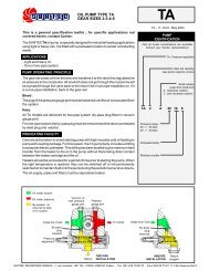
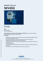
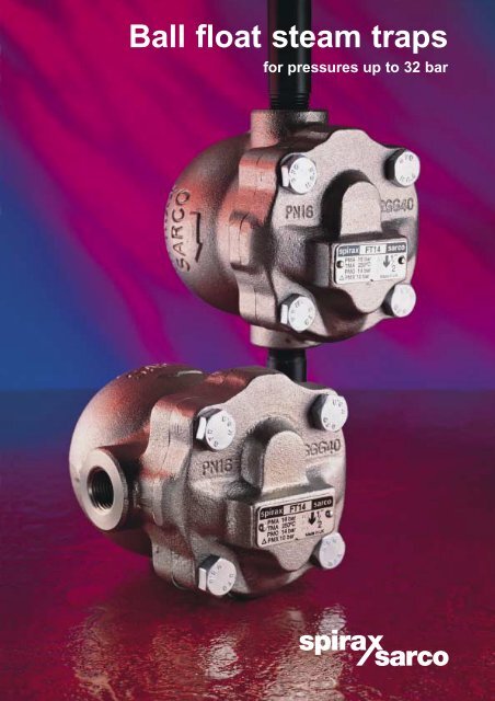
<strong>Ball</strong> float steam traps<br />
<strong>for</strong> pressures <strong>up</strong> <strong>to</strong> <strong>32</strong> <strong>bar</strong>
2<br />
The only ball float steam trap with<br />
over 50 years of experience and<br />
constant development<br />
The Spirax Sarco FT is the product of experience.<br />
First launched in the 1940's the FT has become the<br />
most advanced ball float steam trap available.<br />
Constant design improvements have made <strong>to</strong>day's<br />
FT an extremely robust steam trap, ideally suited <strong>to</strong><br />
the rigorous demands of any steam system.<br />
Unique amongst all ball float steam traps is the<br />
self-aligning main valve, waterhammer proof float<br />
assembly and corrosion resistant air vent.<br />
Such attention <strong>to</strong> detail ensures complete shut-off at<br />
all pressures and reliable operation <strong>for</strong> extended<br />
product life and minimal maintenance.<br />
Having an integral air vent and the options of a steam<br />
lock release (SLR) and drain cock tapping, the FT<br />
range is adaptable <strong>to</strong> all applications where ball float<br />
traps are recommended and instantaneous removal<br />
of condensate is required.<br />
With over three and a half million Spirax Sarco<br />
FT traps s<strong>up</strong>plied <strong>to</strong> over 100 000 cus<strong>to</strong>mers the<br />
Spirax Sarco FT has become the most widely used<br />
ball float steam trap in the world <strong>to</strong>day.<br />
Range and options<br />
Note: SLR is not available on FT43 and FT44 DN80 / DN100 and all vertical versions of FT43, FT44 and FT47.<br />
<strong>32</strong> <strong>bar</strong> versions of all float traps are only provided with a thermostatic air vent.<br />
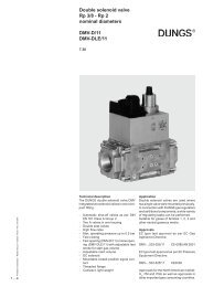
Corrosion resistant stainless steel<br />
capsule type thermostatic element<br />
<strong>for</strong> near <strong>to</strong> steam temperature<br />
air venting.<br />
Air vent increases cold<br />
condensate start-<strong>up</strong> capacity.<br />
Waterhammer proof float<br />
and lever mechanism.<br />
Asbes<strong>to</strong>s free gasket.<br />
Connections Material Universal C<br />
Trap Body design Size - DN Screwed Flanged Socket Cast SG Cast Stainless or vertical/ ENP version Drain<br />
type rating 15 20 25 <strong>32</strong> 40 50 80 100 weld iron iron steel steel horizontal with with cock<br />
flow strainer SLR tapping<br />
FT14 PN16 ● ● ● ● ● ● ● ● ● ● ● ● ● ●<br />
FT14HC PN25 ● ● ● ● ●<br />
FT43 PN16 ● ● ● ● ● ● ● ● ● ● ● ●<br />
FT47 PN40 ● ● ● ● ● ● ● ● ● ●<br />
FT450 ANSI 300 ● ● ● ● ● ● ● ● ● ● ● ●<br />
FT44 PN40 ● ● ● ● ● ● ● ● ● ● ● ●<br />
FT16 PN25 ● ● ● ● ● ●<br />
FT46 PN40 ● ● ● ● ● ● ● ● ●
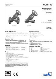
FT14-C shown<br />
1 2<br />
Cover can be rotated <strong>to</strong> suit<br />
pipework configuration (FT14 only).<br />
Others available in either<br />
horizontal or vertical orientation.<br />
<strong>Steam</strong> lock release option.<br />
Variety of seats optimises<br />
capacity at all pressures.<br />
Self-aligning main valve.<br />
Materials and pipe connections<br />
<strong>to</strong> suit every application.<br />
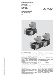
How it works<br />
On start-<strong>up</strong> a thermostatic air vent allows air <strong>to</strong><br />
by-pass the main valve (1) which would otherwise be<br />
unable <strong>to</strong> escape (a condition known as 'air-binding')<br />
As soon as condensate reaches the trap, the float is<br />
raised and the lever mechanism opens the main<br />
valve (2). Hot condensate closes the air vent but<br />
continues <strong>to</strong> flow through the main valve. When steam<br />
arrives the float drops and closes off the main valve,<br />
which remains at all times below the water level,<br />
ensuring that live steam cannot be passed.<br />
In syphon drip pipes draining rotating cylinders or<br />
long drain lines, a steam pocket may <strong>for</strong>m which can<br />
prevent condensate from reaching the trap (a condition<br />
known as 'steam locking'). If this is likely, a steam lock<br />
release (SLR) should be specified <strong>to</strong> bleed away the<br />
steam (3).<br />
User benefits<br />
● Compact and lightweight reducing installation<br />
costs.<br />
● Immediate discharge with clean tight shut-off.<br />
No back-<strong>up</strong> of condensate ensures maximum<br />
plant efficiency.<br />
● Robust construction <strong>to</strong> guarantee long life<br />
against waterhammer and vibration.<br />
● Can be installed in both horizontal and vertical<br />
positions reducing installation problems.<br />
● Large discharge capacity in relation <strong>to</strong> size.<br />
● Stainless steel internals that can <strong>to</strong>lerate<br />
corrosive condensate.<br />
● Spirax Sarco's guarantee of technical back-<strong>up</strong><br />
knowledge and service.<br />
3<br />
3
4<br />
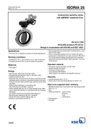
Typical applications<br />
<strong>Ball</strong> float traps are the first choice <strong>for</strong> applications where the rate of heat transfer is high <strong>for</strong> the area of heating<br />
surface available: they are able <strong>to</strong> handle heavy or light condensate loads equally well and are not disturbed by wide<br />
and sudden fluctuations of pressures. Although compact in size, their discharge capacity is high and continuous<br />
ensuring maximum heat transfer: they are the best choice <strong>for</strong> draining both batch and continuous process plant with<br />
au<strong>to</strong>matic temperature control. On all applications condensate is removed immediately it is <strong>for</strong>med.<br />
Jacketed vessels<br />
High productivity can only be achieved by fast<br />
and efficient removal of condensate<br />
and incondensible gases.<br />
Unit heaters,<br />
heater batteries and driers<br />
Since a large volume of condensate is produced<br />
from a small space, any accumulation of condensate<br />
or air causes uneven temperatures, poor control<br />
and corrosion. A float trap ensures efficient<br />
drainage when under positive differential pressure.<br />
Separa<strong>to</strong>r drainage<br />
Separa<strong>to</strong>r efficiency can only be maintained by removing condensate<br />
as it is <strong>for</strong>med which makes the float trap the ideal choice.<br />
Heat exchangers<br />
The float trap is ideal <strong>for</strong> handling a<br />
variable load normally associated with<br />
temperature controlled heat exchangers.<br />
Air and incondensible gases are also<br />
discharged efficiently <strong>to</strong> ensure rapid<br />
warm-<strong>up</strong> during start-<strong>up</strong> conditions.
FT14<br />
Iron screwed<br />
½" – 1"<br />
Sizes and pipe connections<br />
½", ¾", 1", 1¼", 1½", 2" screwed BSP or NPT<br />
DN15, 20, 25 flanged BS 4504 PN16, ANSI 150 and JIS/KS 10<br />
FT14 - ½", ¾", 1" (DN15, 20, 25) horizontal / vertical connection<br />
FT14 - 1"HC, 1¼", 1½" 2" horizontal only (<strong>for</strong>mally FT10)<br />
FT14X has an inbuilt strainer screen.<br />
1"HC – 2"<br />
(<strong>for</strong>mally FT10)<br />
Body/cover<br />
(½",¾", 1", 1"HC, 1¼") SG iron DIN 1693 GGG 40 / 40.3<br />
FT14 (1½", 2") Cast iron DIN 1691 GG25<br />
Bolting Steel BS 3692 Gr. 8.8/ASTM A193 B7<br />
Gasket Rein<strong>for</strong>ced exfoliated graphite<br />
Internals Stainless steel<br />
Limiting conditions (ISO 6552)<br />
Body design conditions PN16<br />
PMA - Maximum allowable pressure 16 <strong>bar</strong> g<br />
TMA - Maximum allowable temperature: -<br />
250°C (½",¾", 1", 1"HC) 220°C (1¼", 1½", 2")<br />
Cold hydraulic test pressure 24 <strong>bar</strong> g<br />
Maximum differential pressure (DPMX)<br />
FT14 - 4.5 (4.5 <strong>bar</strong>) FT14 - 10 (10 <strong>bar</strong>) FT14 - 14 (14 <strong>bar</strong>)<br />
A<br />
B<br />
Materials<br />
A<br />
FT14 (½"-1") FT14 (1"HC-2")<br />
D<br />
C<br />
E<br />
E<br />
D<br />
F<br />
G<br />
Condensate kg / h<br />
30 000<br />
20 000<br />
10 000<br />
8 000<br />
5 000<br />
4 000<br />
3 000<br />
2 000<br />
1 000<br />
500<br />
400<br />
300<br />
200<br />
100<br />
Differential pressure psi<br />
2 3 4 5 10 20 30 50 100 200<br />
1" FT14-10<br />
1", FT14-14<br />
Capacities<br />
2" FT14-4.5<br />
1½" FT14-4.5<br />
1½" FT14-10<br />
1" HC & 1¼" FT14-4.5<br />
1½" FT14-4.5<br />
1" HC & 1¼" FT14-14<br />
½", ¾" DN15, 20 FT14-4.5<br />
½", ¾", DN15, 20 FT14-10<br />
60 000<br />
50 000<br />
40 000<br />
30 000<br />
20 000<br />
10 000<br />
5 000<br />
4 000<br />
3 000<br />
2 000<br />
1 000<br />
500<br />
400<br />
300<br />
200<br />
50<br />
100<br />
40<br />
30 70<br />
0.1 0.2 0.3 0.5 1 2 3 4 5 1014<br />
Differential pressure <strong>bar</strong> (x 100 = kPa)<br />
Note: Capacity shown above is based on discharge at saturation<br />
temperature. When discharge sub-cooled condensate the air vent<br />
provides extra capacity.<br />
Temperature °C<br />
½", ¾", DN15, 20 FT14-14<br />
2" FT14-10<br />
2"<br />
FT14-14<br />
1½" FT14-14<br />
Operating range<br />
1" HC & 1¼"<br />
FT14-10<br />
Pressure psi g<br />
0<br />
250<br />
29 58 87 116 145 174 203 2<strong>32</strong><br />
482<br />
200<br />
150<br />
100<br />
1¼" - 2" (220°C)<br />
<strong>Steam</strong> saturation curve<br />
392<br />
302<br />
212<br />
50<br />
122<br />
0<br />
0 2 4 6 8 10 12 14<br />
<strong>32</strong><br />
16<br />
Pressure <strong>bar</strong> g<br />
The product must not be used in red area.<br />
Dimensions (approximate in millimetres)<br />
Size A A A B C D E F G Weight<br />
PN/ANSI JIS/KS kg<br />
½" 121 - - 107 67 147 105 - - 2.9<br />
¾" 121 - - 107 67 147 105 - - 2.9<br />
1" 145 - - 107 75 166 110 - - 4.0<br />
1"HC 120 - - 110 80 195 160 220 115 6.8<br />
1¼" 120 - - 110 80 195 160 220 115 6.8<br />
1½" 270 - - 130 108 238 200 270 115 17.5<br />
2" 300 - - 138 125 250 200 288 140 22.0<br />
DN15 - 150 150 107 101 152 115 - - 4.5<br />
DN20 - 150 150 107 101 156 115 - - 5.0<br />
DN25 - 160 170 117 70 170 120 - - 6.5<br />
B<br />
B<br />
C<br />
A<br />
FT14 (DN15 / DN20) FT14 (DN25)<br />
E<br />
D<br />
C<br />
D<br />
C<br />
Condensate lb / h<br />
Temperature °F<br />
E<br />
5
6<br />
FT43 Iron flanged<br />
DN80<br />
and DN100<br />
DN15 – DN50<br />
Sizes and pipe connections<br />
DN15, 20, 25, 40, 50, 80 and 100 flanged BS 4504 PN16<br />
ANSI flanges available on request<br />
DN15 - 50 horizontal / vertical connection<br />
DN80 - 100 horizontal<br />
Materials<br />
DN15 - 50<br />
Body/cover<br />
DN80 - 100<br />
Cast iron<br />
Cast iron<br />
DIN 1691 GG25<br />
DIN 1691 GG20<br />
Bolting<br />
DN15 - 50<br />
DN80 - 100<br />
Steel<br />
Steel<br />
BS 3692 Gr. 8.8<br />
BS 3692 Gr. 8.8 and<br />
BS 4439 Gr. 8.8<br />
Gasket Rein<strong>for</strong>ced exfoliated graphite<br />
Internals Stainless steel<br />
Limiting conditions (ISO 6552)<br />
Body design conditions PN16<br />
PMA - Maximum allowable pressure 16 <strong>bar</strong> g<br />
TMA - Maximum allowable temperature 220°C<br />
Cold hydraulic test pressure 24 <strong>bar</strong> g<br />
Maximum differential pressure (D PMX)<br />
FT43 - 4.5 (4.5 <strong>bar</strong>) FT43 - 10 (10 <strong>bar</strong>) FT43 - 14 (14 <strong>bar</strong>)<br />
Capacities<br />
50<br />
40<br />
30<br />
100<br />
20<br />
50<br />
0.1 0.2 0.3 0.5 1 2 3 4 5 1014<br />
Differential pressure <strong>bar</strong> (x 100 = kPa)<br />
Note: Capacity shown above is based on discharge at saturation<br />
temperature. When discharge sub-cooled condensate the air vent<br />
provides extra capacity.<br />
A<br />
FT43 (DN15 - DN50)<br />
E<br />
D<br />
F<br />
A<br />
F<br />
D<br />
Dimensions (approximate in millimetres)<br />
B<br />
C<br />
60 000<br />
50 000<br />
40 000<br />
30 000<br />
20 000<br />
Condensate kg / h<br />
10 000<br />
5 000<br />
4 000<br />
3 000<br />
2 000<br />
Temperature °C<br />
1 000<br />
500<br />
400<br />
300<br />
200<br />
100<br />
Differential pressure psi<br />
2 3 4 5 10 20 30 50 100 200<br />
Operating range<br />
Pressure psi g<br />
0 29<br />
220<br />
200 A, B<br />
58 87 116 145 174 203 2<strong>32</strong><br />
428<br />
392<br />
150<br />
302<br />
100 <strong>Steam</strong> saturation curve<br />
212<br />
50<br />
B<br />
0<br />
0 2 4 6 8 10 12 14<br />
Pressure <strong>bar</strong> g<br />
The product must not be used in red area<br />
A - A Flanged BS 4504 PN16<br />
122<br />
A<br />
<strong>32</strong><br />
16<br />
B - B Flanged ANSI 150 flat face (DN15, 20, 80 and 100),<br />
ANSI 125 (DN25 - 50)<br />
Size A B C D E F Weight (kg)<br />
DN15 150 54 54 188 110 155 5.5<br />
DN20 150 54 54 195 110 165 5.5<br />
DN25 160 110 80 245 160 215 8.3<br />
DN40 230 128 110 330 200 200 21.5<br />
DN50 230 140 126 340 200 225 21.5<br />
DN80 350 140 123 387 200 310 72.0<br />
DN100 350 140 123 387 200 310 74.0<br />
B<br />
C<br />
E<br />
DN80 & 100 FT43-4.5<br />
DN80 & 100 FT43-10<br />
DN50 FT43-4.5<br />
DN40 FT43-4.5<br />
DN40 FT43-10<br />
DN25 FT43-4.5<br />
DN25 FT43-10<br />
DN25 FT43-14<br />
DN15, 20 FT43-4.5<br />
DN15, 20 FT43-10<br />
DN15, 20 FT43-14<br />
DN50 FT43-10<br />
DN40 FT43-14<br />
DN80 &<br />
DN100<br />
FT43-14<br />
DN50<br />
FT43-14<br />
20 000<br />
10 000<br />
5 000<br />
4 000<br />
3 000<br />
2 000<br />
1 000<br />
500<br />
400<br />
300<br />
200<br />
E<br />
F<br />
D<br />
FT43 (DN80 / DN100)<br />
100 000<br />
50 000<br />
40 000<br />
30 000<br />
Condensate lb / h<br />
Temperature °F
FT47 DIN specification<br />
SG iron flanged<br />
Sizes and pipe connections<br />
DN15, 20, 25, 40 and 50 flanged BS 4504 PN40<br />
ANSI flanges available on request<br />
Materials<br />
Body/cover SG iron DIN 1693 GGG 40.3<br />
Bolting Steel DIN 17240 21 Cr Mo V57<br />
Gasket Rein<strong>for</strong>ced exfoliated graphite<br />
Internals Stainless steel<br />
Body and cover from TÜV approved foundry.<br />
Limiting conditions (ISO 6552)<br />
Body design conditions PN40<br />
PMA - Maximum allowable pressure 40 <strong>bar</strong> g<br />
TMA - Maximum allowable temperature 300°C<br />
Cold hydraulic test pressure 60 <strong>bar</strong> g<br />
Maximum differential pressure (D PMX)<br />
DN FT47-4.5 FT47-10 FT47-14 FT47-21 FT47-<strong>32</strong><br />
15,20,25 4.5 <strong>bar</strong> 10 <strong>bar</strong> 14 <strong>bar</strong> 21 <strong>bar</strong> <strong>32</strong> <strong>bar</strong><br />
40,50 4.5 <strong>bar</strong> 10 <strong>bar</strong> - 21 <strong>bar</strong> <strong>32</strong> <strong>bar</strong><br />
A<br />
E<br />
Condensate kg / h<br />
30 000<br />
20 000<br />
Size A B C D E F Weight (kg)<br />
DN15 150 80 80 215 120 155 10.8<br />
DN20 150 80 80 225 120 165 10.8<br />
DN25 160 115 85 276 170 215 15.0<br />
DN40 230 130 115 <strong>32</strong>6 200 200 33.0<br />
DN50 230 141 123 3<strong>32</strong> 200 225 43.0<br />
Capacities<br />
Differential pressure psi<br />
2 3 4 5 10 20 30 50 100 200 400<br />
60 000<br />
50 000<br />
40 000<br />
30 000<br />
10<br />
0.1 0.2 0.3 0.5 1 2 3 4 5 10 20 <strong>32</strong><br />
Differential pressure <strong>bar</strong> (x 100 = kPa)<br />
Note: Capacity shown above is based on discharge at saturation<br />
temperature. When discharge sub-cooled condensate the air vent<br />
provides extra capacity.<br />
Temperature °C<br />
10 000<br />
5 000<br />
4 000<br />
3 000<br />
2 000<br />
1 000<br />
500<br />
400<br />
300<br />
200<br />
100<br />
50<br />
40<br />
30<br />
20<br />
Dimensions (approximate in millimetres)<br />
Operating range<br />
0<br />
300<br />
A, B<br />
150<br />
Pressure psi g<br />
300 450 500<br />
572<br />
200<br />
100<br />
<strong>Steam</strong><br />
saturation curve<br />
292<br />
212<br />
0<br />
0 10<br />
B<br />
20 30<br />
A<br />
<strong>32</strong><br />
40<br />
Pressure <strong>bar</strong> g<br />
The product must not be used in red area<br />
A - A Flanged BS 4504 PN40<br />
B - B Flanged ANSI 150<br />
D<br />
F<br />
DN50 FT47-4.5<br />
DN50 FT47-10<br />
DN40 FT47-4.5<br />
DN40 FT47-10<br />
DN25 FT47-4.5<br />
DN25 FT47-10<br />
DN25 FT47-14<br />
DN15 & DN20 FT47-4.5<br />
DN15 & DN20 FT47-10<br />
DN15 & DN20 FT47-14<br />
DN15 & DN20 FT47-21<br />
DN15 & DN20 FT47-<strong>32</strong><br />
B<br />
C<br />
DN25 FT47-21<br />
DN25 FT47-<strong>32</strong><br />
DN50<br />
FT47-21-<strong>32</strong><br />
FT47-21-<strong>32</strong><br />
20 000<br />
10 000<br />
5 000<br />
4 000<br />
3 000<br />
2 000<br />
1 000<br />
500<br />
400<br />
300<br />
200<br />
100<br />
50<br />
40<br />
30<br />
Condensate lb / h<br />
Temperature °F<br />
7
8<br />
FT450 ASTM specification<br />
Steel screwed<br />
Socket weld<br />
Flanged<br />
DN20 – DN50<br />
150 000<br />
100 000<br />
50 000<br />
40 000<br />
30 000<br />
20 000<br />
10 000<br />
h / lb Condensate<br />
DN80 and DN100<br />
5 000<br />
4 000<br />
3 000<br />
10 000<br />
2 000<br />
5 000<br />
-21 4 000<br />
1 000<br />
Sizes and pipe connections<br />
DN20, 25, 40, 50, 80 and 100 screwed NPT,<br />
socket weld, flanged BS 1560 class 150, 300 or 600<br />
Materials<br />
Body/cover Steel ASTM A216 WCB<br />
Bolting Steel<br />
ASTM A193 B7 and<br />
A194 2H<br />
Gasket Rein<strong>for</strong>ced exfoliated graphite<br />
Internals Stainless steel<br />
Limiting conditions (ISO 6552)<br />
Body design conditions ANSI 300<br />
PMA - Maximum allowable pressure 50 <strong>bar</strong> g<br />
TMA - Maximum allowable temperature 400°C<br />
Cold hydraulic test pressure 75 <strong>bar</strong> g<br />
Maximum differential pressure (D PMX)<br />
FT450-4.5 (4.5 <strong>bar</strong>) FT450-10 (10 <strong>bar</strong>) FT450-14 (14 <strong>bar</strong>)<br />
FT450-21 (21 <strong>bar</strong>) FT450-<strong>32</strong> (<strong>32</strong> <strong>bar</strong>)<br />
A<br />
A1<br />
FT450 (DN20 - DN50)<br />
E<br />
D<br />
F<br />
B<br />
C<br />
Condensate kg / h<br />
500<br />
400<br />
300<br />
200<br />
Differential pressure psi<br />
2 3 4 5 10 20 30 50 100 200 400<br />
200 000<br />
150 000<br />
100 000<br />
DN40 FT450-10<br />
DN80 & 100 FT450<br />
DN50 FT450-4.5<br />
DN40 FT450-4.5<br />
DN25 FT450-4.5<br />
DN25 FT450-10<br />
DN25 FT450-14<br />
DN20 FT45-4.5<br />
DN40 FT450-14-21-<strong>32</strong><br />
50 000<br />
40 000<br />
30 000<br />
20 000<br />
3 000<br />
2 000<br />
1 000<br />
100<br />
500<br />
400<br />
300<br />
50<br />
40<br />
30<br />
200<br />
100<br />
20<br />
50<br />
30<br />
10<br />
0.1 0.2 0.3 0.5 1 2 3 4 5 10 20 <strong>32</strong><br />
Differential pressure <strong>bar</strong> (x 100 = kPa)<br />
Note: Capacity shown above is based on discharge at saturation<br />
temperature. When discharge sub-cooled condensate the air vent<br />
provides extra capacity.<br />
DN20 FT450-10<br />
DN20 FT450-14<br />
DN20 FT450-<strong>32</strong><br />
FT450-10<br />
FT450<br />
-14-21-<strong>32</strong><br />
FT450<br />
DN25 FT450-<strong>32</strong><br />
0<br />
400<br />
150 300 450 550 725<br />
752<br />
300<br />
200<br />
100<br />
A, B<br />
<strong>Steam</strong><br />
saturation curve<br />
572<br />
392<br />
212<br />
0<br />
0 10<br />
B<br />
20 30 40<br />
A<br />
<strong>32</strong><br />
50<br />
Pressure <strong>bar</strong> g<br />
Size A A1 B C D E F Weight (kg)<br />
DN20 155 255 65 65 163 120 189 10.8<br />
DN25 165 257 115 84 208 160 234 15.0<br />
DN40 250 356 130 80 250 195 282 29.0<br />
DN50 300 406 141 90 255 195 295 <strong>32</strong>.0<br />
DN80 705 988 431 171 203 813 444 220.0<br />
DN100 - 988 431 171 203 813 444 220.0<br />
Temperature °C<br />
Capacities<br />
Operating range<br />
Pressure psi g<br />
The product must not be used in red area.<br />
A - A Screwed, socket weld, flanged ANSI 300 and 600<br />
B - B Flanged ANSI 150<br />
A<br />
A1<br />
Dimensions (approximate in millimetres)<br />
E<br />
B<br />
C<br />
F<br />
D<br />
FT450 (DN80 / DN100)<br />
Temperature °F
FT44 DIN specification<br />
Steel flanged<br />
DN80 and DN100<br />
DN15 – DN50<br />
Sizes and pipe connections<br />
DN15, 20, 25, 40, 50, 80 and 100 flanged BS 4504 PN40,<br />
BS 1560 class 150 or 300<br />
DN15 - 50 horizontal / vertical connection<br />
DN80 - 100 horizontal<br />
Materials<br />
Body/cover Steel DIN 17245 GS-C25N<br />
Bolting<br />
DN15 - 50<br />
DN80 - 100<br />
Steel<br />
Steel<br />
DIN 17240 21 Cr MoV57 and<br />
24 Cr Mo5<br />
BS 4439 B7 and<br />
BS 3692 2H<br />
Gasket Rein<strong>for</strong>ced exfoliated graphite<br />
Internals Stainless steel<br />
Body and cover from TÜV approved foundry.<br />
Limiting conditions (ISO 6552)<br />
Body design conditions PN40<br />
PMA - Maximum allowable pressure 40 <strong>bar</strong> g<br />
TMA - Maximum allowable temperature 400°C<br />
Cold hydraulic test pressure 60 <strong>bar</strong> g<br />
Maximum differential pressure (D PMX)<br />
FT44-4.5 (4.5 <strong>bar</strong>) FT44-10 (10 <strong>bar</strong>) FT44-14 (14 <strong>bar</strong>)<br />
FT44-21 (21 <strong>bar</strong>) FT44-<strong>32</strong> (<strong>32</strong> <strong>bar</strong>)<br />
B<br />
C<br />
50 000<br />
40 000<br />
30 000<br />
20 000<br />
Capacities<br />
10<br />
0.1 0.2 0.3 0.5 1 2 3 4 5 10 20 <strong>32</strong><br />
Differential pressure <strong>bar</strong> (x 100 = kPa)<br />
Note: Capacity shown above is based on discharge at saturation<br />
temperature. When discharge sub-cooled condensate the air vent<br />
provides extra capacity.<br />
Operating range<br />
0<br />
400<br />
150 300 450 580<br />
752<br />
300<br />
A, B<br />
572<br />
200<br />
100<br />
0<br />
0 10<br />
<strong>Steam</strong><br />
saturation<br />
B<br />
curve<br />
20 30 <strong>32</strong><br />
Pressure <strong>bar</strong> g<br />
392<br />
212<br />
A<br />
<strong>32</strong><br />
40<br />
The product must not be used in red area<br />
A - A Flanged ANSI 300, PN40<br />
B - B Flanged ANSI 150<br />
Size A A A B C D E F Weight (kg)<br />
CI.300 CI.150 PN40<br />
DN15 209 203 150 80 80 215 120 155 10.8<br />
DN20 209 205 150 80 80 225 120 165 10.8<br />
DN25 212 208 160 115 85 282 170 215 15.0<br />
DN40 <strong>32</strong>7 <strong>32</strong>1 230 130 115 337 200 200 33.0<br />
DN50 <strong>32</strong>0 313 230 141 123 347 200 225 43.0<br />
DN80 373 373 373 140 123 340 200 310 95.0<br />
DN100 366 350 350 140 123 390 200 310 97.0<br />
Temperature °C<br />
10 000<br />
5 000<br />
4 000<br />
3 000<br />
2 000<br />
Differential pressure psi<br />
2 3 4 5 10 20 30 50 100 200 400<br />
100 000<br />
Pressure psi g<br />
A<br />
E<br />
D<br />
F<br />
A<br />
E<br />
F<br />
D<br />
F<br />
D<br />
E<br />
FT44 (DN15 - DN50) FT44 (DN80 and DN100)<br />
Dimensions (approximate in millimetres)<br />
Condensate kg / h<br />
1 000<br />
500<br />
400<br />
300<br />
200<br />
100<br />
50<br />
40<br />
30<br />
20<br />
DN40 FT44-21-<strong>32</strong><br />
DN80 & 100 FT44-4.5<br />
DN80 & 100 FT44-10<br />
DN50 FT44-4.5<br />
DN40 FT44-4.5<br />
DN25 FT44-4.5<br />
DN25 FT44-14<br />
DN15 & 20 FT44-4.5<br />
DN15 & 20 FT44-10<br />
DN15 & 20 FT44-14<br />
DN15 & 20 FT44-21<br />
DN15 & 20 FT44-<strong>32</strong><br />
B<br />
C<br />
DN80<br />
DN50 FT44-10<br />
DN40 FT44-10<br />
DN25 FT44-21<br />
& DN100 FT44-21<br />
DN25 FT44-10<br />
FT44<br />
-21-<strong>32</strong><br />
DN25<br />
FT44-<strong>32</strong><br />
60 000<br />
50 000<br />
40 000<br />
30 000<br />
20 000<br />
10 000<br />
5 000<br />
4 000<br />
3 000<br />
2 000<br />
1 000<br />
500<br />
400<br />
300<br />
200<br />
100<br />
50<br />
40<br />
30<br />
Condensate lb / h<br />
Temperature °F<br />
9
10<br />
FT16 Austenitic stainless steel<br />
Screwed<br />
Sizes and pipe connections<br />
½", ¾" and 1" screwed BSP or NPT<br />
FT16 - horizontal connection<br />
Materials<br />
Body/cover Stainless steel AISI 316L<br />
Bolting Stainless steel A2 Gr. 80<br />
Gasket Austenitic stainless steel<br />
Internals Stainless steel<br />
Limiting conditions (ISO 6552)<br />
Body design conditions PN25<br />
PMA - Maximum allowable 25 <strong>bar</strong> g<br />
TMA - Maximum allowable temperature 300°C<br />
Cold hydraulic test pressure 38 <strong>bar</strong> g<br />
Maximum differential pressure (D PMX)<br />
FT16-4.5 (4.5 <strong>bar</strong>) FT16-10 (10 <strong>bar</strong>) FT16-14 (14 <strong>bar</strong>)<br />
A<br />
E<br />
Condensate kg / h<br />
Temperature °C<br />
3 000<br />
2 000<br />
1 000<br />
500<br />
400<br />
300<br />
200<br />
100<br />
50<br />
40<br />
Size A B C D E F G Weight (kg)<br />
½" 120 54 54 148 110 169 45 4.0<br />
¾" 120 54 54 148 110 169 45 4.0<br />
1" 120 110 80 195 160 220 115 6.8<br />
Capacities<br />
Differential pressure psi<br />
2 3 4 5 10 20 30 50<br />
70<br />
30<br />
0.1 0.2 0.3 0.5 1 2 3 4 5 10 14<br />
Differential pressure <strong>bar</strong> (x 100 = kPa)<br />
Note: Capacity shown above is based on discharge at saturation<br />
temperature. When discharge sub-cooled condensate the air vent<br />
provides extra capacity.<br />
Operating range<br />
Pressure psi g<br />
0<br />
300<br />
50 150 250 350 362<br />
572<br />
200<br />
292<br />
100<br />
<strong>Steam</strong><br />
saturation curve<br />
212<br />
0<br />
0 5 10 15 16.5 20<br />
<strong>32</strong><br />
25<br />
Pressure <strong>bar</strong> g<br />
The product must not be used in red area.<br />
Dimensions (approximate in millimetres)<br />
D<br />
F<br />
G<br />
1" FT16-4.5<br />
1" FT16-10<br />
1" FT16-14<br />
½", ¾" FT16-4.5<br />
½", ¾" FT16-10<br />
½", ¾" FT16-14<br />
B<br />
C<br />
100<br />
200<br />
6 000<br />
5 000<br />
4 000<br />
3 000<br />
2 000<br />
1 000<br />
500<br />
400<br />
300<br />
200<br />
100<br />
Condensate lb / h<br />
Temperature °F
FT46 DIN specification<br />
Austenitic stainless steel<br />
Flanged<br />
Sizes and pipe connections<br />
DN15, 20, 25, 40 and 50 flanged BS 4504 PN40<br />
ANSI flanges available on request<br />
FT46 –horizontal connection<br />
Materials<br />
Body/cover Stainless steel AISI 316<br />
Bolting Stainless steel A2 Gr. 80<br />
Gasket Austenitic stainless steel<br />
Internals Stainless steel<br />
Body and cover from TÜV approved foundry.<br />
Limiting conditions (ISO 6552)<br />
Body design conditions PN40<br />
PMA - Maximum allowable pressure 40 <strong>bar</strong> g<br />
TMA - Maximum allowable temperature 400°C<br />
Cold hydraulic test pressure 60 <strong>bar</strong> g<br />
Maximum differential pressure (D PMX)<br />
FT46-4.5 (4.5 <strong>bar</strong>) FT46-10 (10 <strong>bar</strong>) FT46-14 (14 <strong>bar</strong>)<br />
FT46-21 (21 <strong>bar</strong>)<br />
A<br />
E<br />
Size A B C D E F Weight (kg)<br />
DN15 150 80 80 215 120 155 10.8<br />
DN20 150 80 80 225 120 165 10.8<br />
DN25 160 115 85 276 170 215 15.0<br />
DN40 230 130 115 <strong>32</strong>6 200 200 33.0<br />
DN50 230 141 123 3<strong>32</strong> 200 225 43.0<br />
Condensate kg / h<br />
Capacities<br />
Differential pressure psi<br />
2 345 10 20 30 50 100 200 300<br />
60 000<br />
50 000<br />
40 000<br />
30 000<br />
50<br />
40<br />
30<br />
100<br />
20<br />
0.1 0.2 0.3 0.5 1 2 3 4 5 10<br />
50<br />
20<br />
Differential pressure <strong>bar</strong> (x 100 = kPa)<br />
Note: Capacity shown above is based on discharge at saturation<br />
temperature. When discharge sub-cooled condensate the air vent<br />
provides extra capacity.<br />
Temperature °C<br />
30 000<br />
20 000<br />
10 000<br />
5 000<br />
4 000<br />
3 000<br />
2 000<br />
1 000<br />
500<br />
400<br />
300<br />
200<br />
100<br />
Dimensions (approx. in millimetres)<br />
Operating range<br />
400<br />
300<br />
200<br />
100<br />
0<br />
0 10 13.6 20 25.5 30 40 <strong>32</strong><br />
Pressure psi g<br />
0 150 300<br />
A<br />
<strong>Steam</strong> saturation curve<br />
B<br />
450 580<br />
752<br />
572<br />
392<br />
B<br />
212<br />
A<br />
Pressure <strong>bar</strong> g<br />
The product must not be used in red area<br />
A - A Flanged ANSI 300, PN40<br />
B - B Flanged ANSI 150<br />
D<br />
F<br />
DN50 FT46-4.5<br />
DN50 FT46-10<br />
DN40 FT46-4.5<br />
DN40 FT46-10<br />
DN25 FT46-4.5<br />
DN25 FT46-10<br />
DN25 FT46-14<br />
DN15 & 20 FT46-4.5<br />
DN15 & 20 FT46-10<br />
DN15 & 20 FT46-14<br />
DN15 & 20 FT46-21<br />
B<br />
C<br />
DN40 FT46-21<br />
DN50 FT46-21<br />
DN25 FT46-21<br />
20 000<br />
10 000<br />
5 000<br />
4 000<br />
3 000<br />
2 000<br />
1 000<br />
500<br />
400<br />
300<br />
200<br />
Condensate lb / h<br />
Temperature °F<br />
11
Installation<br />
<strong>Float</strong> traps should be installed as close <strong>to</strong> the drain<br />
outlet as possible, with the float arm horizontal and<br />
with the direction of flow as indicated on the body.<br />
A strainer should be fitted in front of the trap. If exposed<br />
<strong>to</strong> freezing conditions, they should always be lagged<br />
or drained.<br />
Options<br />
SLR (<strong>Steam</strong> lock release):- a manually adjustable<br />
needle valve <strong>for</strong> applications where traps are subject<br />
<strong>to</strong> steam locking.<br />
Drain cock tapping:- the cover can be drilled and<br />
screwed 3 /8" <strong>for</strong> the purpose of fitting a drain cock<br />
(½" on FT14).<br />
<strong>Steam</strong> trap leakage detection:- <strong>for</strong> au<strong>to</strong>matically<br />
moni<strong>to</strong>ring steam trap per<strong>for</strong>mance consider the use<br />
of Spiratec. Separate literature is available on request.<br />
Typical specification<br />
The steam traps shall be Spirax Sarco FT14 float<br />
and lever design having an in-built stainless steel<br />
capsule type air vent. The trap shall be manufactured<br />
in SG iron <strong>to</strong> grade GGG 40 and have connections<br />
screwed ½" BSP. The trap shall be capable of operating<br />
with a maximum differential pressure of 14 <strong>bar</strong>.<br />
Some of the products may not be available in certain markets.<br />
Spirax-Sarco Limited, Charl<strong>to</strong>n House,<br />
Cheltenham, Gloucestershire, GL53 8ER UK.<br />
Tel: +44 (0)1242 521361 Fax: +44 (0)1242 573342<br />
E-mail: Enquiries@SpiraxSarco.com<br />
Internet: www.SpiraxSarco.com<br />
© Copyright 2001 Spirax Sarco is a registered trademark of Spirax-Sarco Limited<br />
SB-S02-01 ST Issue 5<br />
FT