Gilflo ILVA flowmeters - Filter
Gilflo ILVA flowmeters - Filter
Gilflo ILVA flowmeters - Filter

Create successful ePaper yourself
Turn your PDF publications into a flip-book with our unique Google optimized e-Paper software.
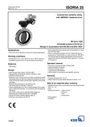
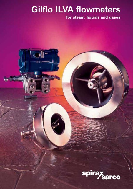
<strong>Gilflo</strong> <strong>ILVA</strong> <strong>flowmeters</strong><br />
for steam, liquids and gases
The <strong>Gilflo</strong> in-line variable area (<strong>ILVA</strong>) flowmeter ...<br />
is a revolutionary development of the well established family of <strong>Gilflo</strong> <strong>flowmeters</strong><br />
that has been used in industrial flowmetering applications for more than 30 years.<br />
Using the same unique operating principle but incorporating a number of significant<br />
design changes, the <strong>Gilflo</strong> <strong>ILVA</strong> flowmeter is perfectly suited for use with most industrial<br />
fluids including steam and gases. A comprehensive range of associated sensors and<br />
electronic instrumentation is available to compliment the <strong>Gilflo</strong> <strong>ILVA</strong> flowmeter<br />
range and make it one of the most adaptable <strong>flowmeters</strong> available.<br />
Why install <strong>flowmeters</strong>?<br />
The main justifications for installing <strong>flowmeters</strong> in any industrial plant are:<br />
n Product quality: By providing management information, they enable a plant to be operated<br />
at peak efficiency thus ensuring product quality is maintained in the most cost effective way.<br />
n Direct cost control: They can be used to cost raw materials or energy sources<br />
(such as compressed air) directly.<br />
How the <strong>Gilflo</strong> <strong>ILVA</strong> flowmeter works<br />
In common with other differential pressure <strong>flowmeters</strong> such as<br />
orifice plates and venturi meters, the <strong>Gilflo</strong> <strong>ILVA</strong> flowmeter primary<br />
element uses the theorem for the conservation of energy in fluid<br />
flow through a pipe.<br />
It operates on the well established spring loaded variable area<br />
(SLVA) principle where the area of an annular orifice is<br />
continuously varied by a moving cone. A centrally positioned cone<br />
is free to move axially against the resistance of a precision<br />
compression spring. This produces a variable differential pressure<br />
across the annular orifice which is sensed by a transmitter<br />
Dp<br />
connected to integral tappings on the flowmeter body. The<br />
pressure difference can then be used to derive an instantaneous<br />
rate of flow based on Bernoulli’s Theorem.<br />
The unique design of the <strong>Gilflo</strong> <strong>ILVA</strong> flowmeter greatly expands the capabilities of the differential pressure<br />
flow measurement. The key to the unique performance of the <strong>Gilflo</strong> <strong>ILVA</strong> flowmeter lies in the design of the<br />
orifice and cone to minimise upstream velocity profile effects and at the same time provide an exceptionally<br />
high turndown flowmeter based on practically achievable line velocities.<br />
Installation benefits<br />
The correct installation of any type of flowmeter is of prime<br />
importance if the manufacturers claims for accuracy and<br />
repeatability are to be achieved in practice. All types of flowmeter<br />
require a certain number of straight, uninterrupted lengths of meter<br />
size pipework upstream and downstream of the point of installation.<br />
Turbine<br />
Vortex<br />
Orifice plate<br />
D <strong>Gilflo</strong> <strong>ILVA</strong><br />
6 D 3 D<br />
In real life, there are often space constraints that severely restrict where and how a flowmeter can be installed. It<br />
is therefore very important to look carefully at where the flowmeter is to be fitted as early as possible. The unique<br />
wafer design of the <strong>Gilflo</strong> <strong>ILVA</strong> flowmeter means that its installed length is much shorter than almost any other<br />
flowmeter. A <strong>Gilflo</strong> <strong>ILVA</strong> flowmeter can often be fitted into lines which were never designed to accept <strong>flowmeters</strong>.<br />
<strong>Gilflo</strong> <strong>ILVA</strong> flowmeter 6 diameters<br />
up to<br />
20 diameters<br />
0<br />
10 20 30<br />
2 Number of upstream diameters of straight pipe<br />
up to<br />
30 diameters<br />
up to<br />
30 diameters
The importance of turndown<br />
DN150 <strong>Gilflo</strong> <strong>ILVA</strong> flowmeter 5 bar g saturated steam<br />
Benefit of large turndown at low flows<br />
<strong>Gilflo</strong> <strong>ILVA</strong> flowmeter<br />
0.6 1 2 2.8 3<br />
Minimum velocity m/s<br />
To ensure that the flow information gathered is accurate<br />
whatever the process conditions or demand, it is essential<br />
that a flowmeter is capable of meeting its specification over<br />
the full operating range from low standing or weekend loads,<br />
right up to the maximum demand of the process. As actual<br />
demands are often unknown or may vary widely, a flowmeter<br />
should have the largest turndown possible based on<br />
practical flow conditions. Great care should be taken that<br />
claims for turndown are based on realistic flow velocities.<br />
For instance, steam systems should be sized on a maximum<br />
flow velocity of about 35 m / s ... higher velocities will<br />
possibly cause erosion and noise problems in the system.<br />
Flowrate kg / h<br />
1 000<br />
750<br />
500<br />
250<br />
Threshold at<br />
4:1 turndown<br />
0<br />
Density<br />
compensation<br />
It is rare for the pressure in<br />
a steam system to remain<br />
absolutely constant. Unless<br />
this variation is taken into<br />
account, flow measurement<br />
errors will occur. The automatic<br />
density compensation options<br />
completely eliminate these<br />
errors and allow accurate<br />
metering whatever the steam<br />
pressure. This is shown in the<br />
adjacent diagram.<br />
Actual flowrate<br />
Turbine typically 10:1<br />
Cumulative error<br />
Cumulative error kg<br />
Vortex meter<br />
Turndown ratios with flow velocities limited to 35 m/s<br />
0<br />
Orifice 4:1<br />
Vortex up to 15:1 depending on operating conditions<br />
20 40 60 80 100<br />
Orifice plate<br />
0 1 2 3 4 5 6 7 8<br />
Hours elapsed<br />
Flowrate below minimum of 250 kg / h (i.e. 1 000 kg / h ÷ 4)<br />
Flowrate kg/ h<br />
1 000<br />
800<br />
600<br />
400<br />
200<br />
0<br />
Actual flowrate<br />
<strong>Gilflo</strong> <strong>ILVA</strong> flowmeter<br />
Actual system pressure<br />
Cumulative error<br />
0 1 2 3 4 5 6 7 8<br />
Hours elapsed<br />
100:1<br />
This graph shows a typical<br />
demand curve for a distributed<br />
steam system with a high<br />
start-up load and variable<br />
demand through the day. An<br />
orifice plate meter with a<br />
4:1 turndown is sized on the<br />
peak load of 1 000 kg / h. Any<br />
flowrates below 250 kg / h are<br />
'lost' or, at best recorded with<br />
a significant error. In this case<br />
1 700 kg have been 'lost'.<br />
The <strong>Gilflo</strong> <strong>ILVA</strong> flowmeter, with<br />
its 100:1 turndown eliminates<br />
this type or error.<br />
In the example above, a simple non-compensated flowmeter is set for 6 bar g. The actual pressure in the system varies through the<br />
day and unless this is allowed for, by the end of the day, very significant errors can arise. This is typical of many steam systems.<br />
2 000<br />
1 700<br />
1 500<br />
1 000<br />
500<br />
0<br />
10<br />
8<br />
6<br />
4<br />
2<br />
0<br />
Pressure bar g<br />
3 500<br />
3 000<br />
2 500<br />
2 000<br />
1 500<br />
1 000<br />
500<br />
0<br />
Cumulative error kg<br />
3
4<br />
<strong>Gilflo</strong> <strong>ILVA</strong> <strong>flowmeters</strong> ...<br />
proven technology in a new package.<br />
Thirty years experience and over 10 000 installations worldwide has firmly<br />
established the technology that gives <strong>Gilflo</strong> <strong>flowmeters</strong> their unequalled<br />
turndown and ultra compact installation. Now the <strong>Gilflo</strong> <strong>ILVA</strong><br />
<strong>flowmeters</strong> uses this wealth of experience in a wafer<br />
design to give even lower cost of ownership.<br />
Designed and supported by Spirax Sarco’s<br />
worldwide supported, the <strong>Gilflo</strong> <strong>ILVA</strong><br />
flowmeter is the logical choice.<br />
Range availability<br />
n Sizes DN50 (2")<br />
to DN200 (8")<br />
n All stainless steel<br />
316L body construction<br />
n Pressure rating to match<br />
flange specifications<br />
n Temperatures up to 450°C<br />
Applications<br />
n Cost metering for<br />
energy management<br />
n Custody transfer<br />
n Process and<br />
control applications<br />
n Boiler load control<br />
Commonly<br />
metered fluids<br />
n Saturated steam<br />
n Superheated steam<br />
n Condensate<br />
n Natural gas<br />
n Nitrogen<br />
n Carbon dioxide<br />
n Compressed air<br />
n Ethylene<br />
n Fuel oil<br />
Flow<br />
direction
All stainless steel<br />
construction.<br />
Alignment webs for easy<br />
installation.<br />
Precision cone.<br />
Wafer design fits between<br />
customer flanges.<br />
Over-range stop prevents<br />
damage from surges or<br />
excessive flows.<br />
Precision heavy duty<br />
nickel cobalt alloy<br />
spring operates up to<br />
450°C without creep.<br />
Pressure tappings built<br />
into the flowmeter body<br />
for easy installation.<br />
User benefits<br />
Suitable for most<br />
industrial fluids.<br />
Excellent turndown,<br />
up to 100:1.<br />
High pipeline unit accuracy,<br />
±1% of reading.<br />
Ultra compact installation,<br />
requires only six pipe<br />
diameters upstream and<br />
three downstream.<br />
Wafer design for easy<br />
installation.<br />
No expensive line size<br />
changes required to achieve<br />
low flow performance.<br />
Intrinsically safe for use in<br />
hazardous areas.<br />
Reliability proven over<br />
30 years experience.<br />
Designed and manufactured<br />
by Spirax Sarco -<br />
a ISO 9001 : 2000<br />
approved company.<br />
<strong>Gilflo</strong> calibration rig, Spirax Sarco, Cheltenham, England<br />
5
6<br />
<strong>Gilflo</strong> <strong>ILVA</strong> <strong>flowmeters</strong> ...<br />
system configurations and associated equipment<br />
EL2230 temperature transmitter<br />
EL2600<br />
pressure<br />
transmitter<br />
M750 display unit<br />
<strong>Gilflo</strong> <strong>ILVA</strong><br />
F50C isolation<br />
valves<br />
M200 series flow computer<br />
<strong>Gilflo</strong> <strong>ILVA</strong><br />
F50C isolation<br />
valves<br />
<strong>Gilflo</strong> <strong>ILVA</strong><br />
F50C isolation<br />
valves<br />
M750 display unit<br />
M640<br />
Steam mass<br />
flow transmitter<br />
M610<br />
differential<br />
pressure<br />
transmitter<br />
M610<br />
differential pressure<br />
transmitter<br />
Note:<br />
The illustrations above are schematic only.<br />
Refer to Installation and Maintenance Instructions for further details.<br />
n M240G (steam) and M250G (gas) flow computers<br />
provide complete information on flow, pressure<br />
and temperature.<br />
n Full density compensation.<br />
n Linearisation of <strong>Gilflo</strong> signal.<br />
n Wall or panel mounting.<br />
n Bright, easy to read display.<br />
n Alarm facilities for fluid flow, pressure and<br />
temperature.<br />
n 4 independent timers.<br />
n Analogue, pulse and EIA232C outputs available<br />
as standard.<br />
n M640 steam mass flow transmitter provides<br />
density compensated 4 - 20 mA output.<br />
n Linearisation of <strong>Gilflo</strong> signal.<br />
n Ideal for applications where density<br />
compensation is essential.<br />
n Suitable for use up to 74 bar g saturated steam.<br />
n HART ® 5.2 in-built.<br />
n Optional local display.<br />
n Intrinsically safe pipeline unit<br />
and mass flow transmitter.<br />
n M750 display unit provides local display of<br />
total flow and rate of flow.<br />
n Suitable for steam and<br />
most industrial fluids and gases.<br />
n Ideal for applications where<br />
fluid density is constant.<br />
n User configurable.<br />
n Linearisation of <strong>Gilflo</strong> signal.<br />
n Retransmission options of rate and / or<br />
total flow available.<br />
n Bright, easy to read display.<br />
n Panel mounting as standard.
Equivalent water flowrate Q E<br />
Mass flow units Volumetric units<br />
Liquids QE =<br />
Ö<br />
qm SG<br />
Calibration of <strong>Gilflo</strong> <strong>ILVA</strong> <strong>flowmeters</strong><br />
All <strong>Gilflo</strong> <strong>ILVA</strong> <strong>flowmeters</strong> are calibrated on a high accuracy flow facility at Spirax Sarco’s manufacturing plant<br />
in Cheltenham, England. Designed and built by Spirax Sarco engineers in conjunction with UK National<br />
Engineering Laboratories, it ensures that every flowmeter meets the highest possible standard of accuracy.<br />
Some basic features of the flow facility are:<br />
n Facility size capability: DN50 to DN300.<br />
n Reference methods: gravimetric and transfer standard electromagnetic meters.<br />
n Flow capacity: up to 19 000 litres/min water.<br />
n Pipework: all 316L stainless steel with upstream and downstream pipework straight runs in excess of recommended lengths.<br />
n Flowmeter location: clamping arrangements ensure <strong>flowmeters</strong> are concentric to pipework to ensure accurate calibration.<br />
n Fully automatic data collection: archiving of all flow data electronically for future reference / recalibration.<br />
n Calibration documentation: full calibration documentation is available with every flowmeter.<br />
Sizing and selection of a <strong>Gilflo</strong> <strong>ILVA</strong> flowmeter<br />
It is important to select the correct size of <strong>Gilflo</strong> <strong>ILVA</strong> flowmeter for a particular application. First principles can be<br />
used as follows, determine the equivalent water flowrate (litres/min) based on the maximum anticipated actual flow,<br />
then select the <strong>Gilflo</strong> <strong>ILVA</strong> best suited to the application using the tables below. Alternatively consult Spirax Sarco.<br />
Gases and<br />
steam<br />
actual flow<br />
conditions<br />
QE =<br />
1 000<br />
qm Ö DF DF<br />
QE = QFÖ 1 000<br />
Gases<br />
QE =<br />
Ö<br />
qm standard DS PF TS x x<br />
conditions 1 000 PS T F<br />
Q E = Q L<br />
Q<br />
E = Q<br />
S<br />
Ö<br />
ÖSG<br />
D S x P S x T F<br />
1 000 P F T S<br />
Using the value of Q E as determined above, select the correct <strong>Gilflo</strong> flowmeter from the table below:<br />
Table of QE Flowmeter type<br />
Maximum QE litres / minute<br />
Maximum DP<br />
Wg<br />
DN50 149 200<br />
DN80 585 200<br />
DN100 1 800 200<br />
DN150 2 900 200<br />
DN200 5 700 200<br />
From the table, it can be seen that a DN50 <strong>Gilflo</strong> <strong>ILVA</strong> flowmeter would<br />
be suitable for this application. Note: 1 m³ / h = 16.667 litres / min.<br />
Where:<br />
Q E = Equivalent water flowrate (litres/min)<br />
qm = Mass flowrate (kg/min)<br />
Q L = Maximum liquid flowrate (litres/min)<br />
Q S = Maximum gas flowrate at standard conditions (litres/min)<br />
Q F = Maximum gas flowrate at actual flow conditions (litres/min)<br />
SG = Specific gravity<br />
D S = Density of gas at standard conditions (kg /m 3 )<br />
D F = Density of gas at actual flow conditions (kg /m 3 )<br />
P S = Standard pressure = 1 . 013 bar a<br />
= 1 . 033 kg / cm 2 a<br />
= 14 . 7 psi a<br />
P F = Actual flow pressure in same absolute units as P S<br />
T S = Standard temperature (K) = °C + 273<br />
T F = Actual flow temperature (K) = °C + 273<br />
Example:<br />
Determine which <strong>Gilflo</strong> pipeline unit is required to measure the<br />
flow of compressed air when:<br />
1: Estimated maximum rate of flow = 500 s m³/h at 7 bar g and 20°C<br />
Note: Standard conditions = 1.013 bar a, 0°C giving a standard<br />
density of 1.29 kg / m³<br />
DS 2: Calculate QE from QE = QS x<br />
Ö<br />
PS x TF 1000 P F T S<br />
Q 1.29 1.013 293<br />
E = (500 x 16.667) x x x<br />
Ö 1000 8.013 273<br />
QE = 110 litres / min.<br />
Sizing the <strong>Gilflo</strong> <strong>ILVA</strong> flowmeter for saturated steam - capacities kg/h<br />
Steam pressure bar g 1 3 5 7 10 12 15 20 25 30 40<br />
DN50<br />
Maximum flow<br />
Minimum flow<br />
300<br />
3<br />
416<br />
4<br />
503<br />
5<br />
577<br />
6<br />
671<br />
7<br />
727<br />
7<br />
804<br />
8<br />
918<br />
9<br />
1 020<br />
10<br />
1 113<br />
11<br />
1 283<br />
13<br />
DN80<br />
Maximum flow<br />
Minimum flow<br />
1 179<br />
12<br />
1 632<br />
16<br />
1 976<br />
20<br />
2 264<br />
23<br />
2 635<br />
26<br />
2 855<br />
29<br />
3 156<br />
32<br />
3 603<br />
36<br />
4 003<br />
40<br />
4 371<br />
44<br />
5 039<br />
50<br />
Maximum flow<br />
DN100<br />
Minimum flow<br />
3 629<br />
36<br />
5 023<br />
50<br />
6 080<br />
61<br />
6 967<br />
70<br />
8 108<br />
81<br />
8 784<br />
88<br />
9 709<br />
97<br />
11 085<br />
111<br />
12 317<br />
123<br />
13 449<br />
134<br />
15 505<br />
155<br />
Maximum flow<br />
DN150<br />
Minimum flow<br />
5 847<br />
58<br />
8 092<br />
81<br />
9 795<br />
98<br />
11 224<br />
112<br />
13 062<br />
131<br />
14 152<br />
142<br />
15 643<br />
156<br />
17 859<br />
179<br />
19 843<br />
198<br />
21 667<br />
217<br />
24 980<br />
250<br />
Maximum flow<br />
DN200<br />
Minimum flow<br />
11 492<br />
115<br />
15 905<br />
159<br />
19 252<br />
193<br />
22 061<br />
221<br />
25 674<br />
257<br />
27 816<br />
278<br />
30 746<br />
307<br />
35 101<br />
351<br />
39 002<br />
390<br />
45 587<br />
426<br />
49 098<br />
491<br />
Note: Maximum flowrates are calculated at a differential pressure across the <strong>Gilflo</strong> <strong>ILVA</strong> pipeline unit of 498 mbar (200" H20).<br />
Minimum measurable flowrate is 1% of maximum.<br />
7
8<br />
<strong>Gilflo</strong> spring design<br />
The design and manufacture of the spring in the <strong>Gilflo</strong> <strong>ILVA</strong> flowmeter is fundamental to its accuracy and long term performance.<br />
n Made from 'aerospace' alloy Inconel X750 which is widely used in jet engine turbine components due to its exceptional high<br />
temperature performance.<br />
n During manufacture, all springs are age hardened at 650°C for 4 hours.<br />
n All springs are 'hot set' at 460°C after manufacture to eliminate any possibility of relaxation at high temperatures.<br />
n Design stress levels range from 11% to 30% UTS ... most springs are designed to stress levels of around 60%.<br />
n In service, all <strong>Gilflo</strong> <strong>ILVA</strong> <strong>flowmeters</strong> incorporate over-range stops to prevent over stressing the spring in overload conditions.<br />
n Many thousands of installations have proved the integrity of the design and manufacture of the spring.<br />
Specification<br />
Operating principle Spring loaded variable area with differential pressure output proportional to rate of flow.<br />
Limiting conditions To ANSI 600 (carbon steel) pressure / temperature envelope.<br />
Sizes available DN50, DN80, DN100, DN150 and DN200<br />
EN 1092 PN16, PN25, PN40<br />
BS 10 Table H<br />
Flange specifications ANSI B 16.5 Class 150, 300, 600<br />
JIS 20<br />
KS 20<br />
Materials of construction<br />
Body and internals: Stainless steel 316L<br />
Spring: Inconel X750<br />
Installation Normally horizontal. For vertical (flow downwards) applications, consult Spirax Sarco.<br />
When used in conjunction with an M200 series flow computer or M750 display unit or M640 steam<br />
Accuracy<br />
mass flow transmitter, pipeline unit accuracy is better than ± 1% of actual flow from 5% to 100% of<br />
maximum rated flow. For flows from 1% to 5% of maximum rated flow, the pipeline unit accuracy<br />
will be better than ± 0.1% FSD.<br />
Repeatability Better than 0.25%.<br />
Unrecovered pressure drop Less than 200 inches water gauge (498 millibar) at maximum flowrate.<br />
Dimensions / Weights (approximate in mm and kg)<br />
Size A B C D E Weight<br />
DN50 35.0 63 130 103 17.5 2.0<br />
DN80 45.0 78 160 138 22.5 3.9<br />
DN100 60.5 103 208 162 37.5 8.3<br />
DN150 75.0 134 300 218 37.5 14.2<br />
DN200 85.0 161 360 273 42.5 23.6<br />
In addition to the <strong>ILVA</strong> range, Spirax Sarco can supply<br />
<strong>Gilflo</strong> <strong>flowmeters</strong> for special requirements in sizes from DN50 to<br />
DN400. These are of flanged, pressure vessel type construction<br />
and can be manufactured to meet most international standards<br />
construction and inspection. Please consult Spirax Sarco for<br />
details.<br />
Some of the products may not be available in certain markets.<br />
D<br />
E<br />
A<br />
B<br />
C<br />
SB-P337-07<br />
Note: Pressure tappings<br />
are threaded ¼" NPT.<br />
(2 off located at 180°)<br />
Spirax-Sarco Limited, Charlton House,<br />
Cheltenham, Gloucestershire, GL53 8ER UK.<br />
Tel: +44 (0)1242 521361 Fax: +44 (0)1242 573342<br />
E-mail: Enquiries@SpiraxSarco.com<br />
Internet: www.SpiraxSarco.com<br />
© Copyright 2003 Spirax Sarco is a registered trademark of Spirax-Sarco Limited<br />
MI Issue 4