Power Plant and Process Burners - Filter
Power Plant and Process Burners - Filter
Power Plant and Process Burners - Filter

You also want an ePaper? Increase the reach of your titles
YUMPU automatically turns print PDFs into web optimized ePapers that Google loves.
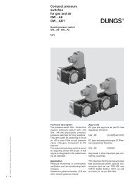
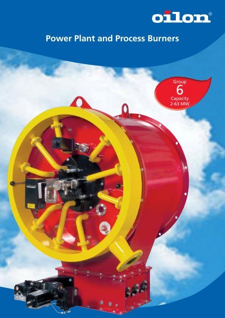
<strong>Power</strong> <strong>Plant</strong> <strong>and</strong> <strong>Process</strong> <strong>Burners</strong><br />
Group<br />
6<br />
Capacity<br />
2-63 MW
<strong>Power</strong> plants<br />
District heating<br />
plants<br />
Pulp <strong>and</strong> paper<br />
Chemical industry<br />
Metallurgic<br />
processes<br />
Municipal waste<br />
incineration<br />
Hazardous waste<br />
incineration<br />
Odorous gas<br />
incineration<br />
Fluidized bed<br />
boilers<br />
Recovery boilers<br />
Marine boilers<br />
Steam boilers<br />
Hot water boilers<br />
Thermal oil boilers<br />
<strong>Process</strong> furnaces<br />
Hot air generators<br />
Other applications
Oilon burner expertise for power plants<br />
<strong>and</strong> industrial processes<br />
Oilon Energy Oy specializes in power plant <strong>and</strong> process<br />
burners which are capable of being used in several different<br />
plants <strong>and</strong> applications. The know-how of valve units,<br />
pumping stations <strong>and</strong> burner automation enables Oilon to<br />
deliver complete combustion systems. In group 6, the atomizing<br />
of fuel is done by means of steam or compressed air.<br />
The burners are duo-block type, i.e. the combustion air is<br />
provided by a separate blower, which can also be included<br />
in the Oilon delivery.<br />
Benefi ts to plant owner<br />
Oilon’s experience of burners <strong>and</strong> auxiliary equipment dates<br />
back from 1961. The main objectives of research <strong>and</strong> development<br />
involve high effi ciency, reliable operation, environmentally<br />
friendly combustion <strong>and</strong> low emissions. The fi ne<br />
tuning of the combustion process is realized by automation<br />
system giving the right kind of controls, based also on the<br />
long experience of Oilon. This combination of expertise<br />
guarantees the optimal performance <strong>and</strong> availability of the<br />
plant.<br />
Pulp <strong>and</strong> paper<br />
Applications<br />
Oilon’s burner technology is utilized in various power plants<br />
<strong>and</strong> industrial processes, such as steam <strong>and</strong> hot water<br />
boilers, district heating plants, hazardous <strong>and</strong> municipal<br />
waste incineration, pulp <strong>and</strong> paper, metallurgic processes,<br />
aluminium production, hot air generators etc.<br />
Fuels<br />
In addition to st<strong>and</strong>ard, commercially available liquid <strong>and</strong><br />
gaseous fuels, Oilon has experience in combustion of numerous<br />
other fuels. These include a wide variety of bio <strong>and</strong><br />
process fuels as well as wastes. All Oilon burner families<br />
have a prearrangement to operate as multi-fuel burners in<br />
which liquids <strong>and</strong> gases can be combusted either separately<br />
or simultaneously.<br />
Metallurgic processes<br />
Hazardous <strong>and</strong> municipal waste incineration Aluminium production<br />
World-wide expertise<br />
Oilon has world-wide experience <strong>and</strong> equipment deliveries<br />
to every continent. Local legislation <strong>and</strong> st<strong>and</strong>ards will<br />
be observed <strong>and</strong> followed. In case of additional emission<br />
requirements coming for example from environmental<br />
permitting, the equipment <strong>and</strong> processes will be designed<br />
to meet those. The experts in Oilon know the circumstances<br />
in different plants <strong>and</strong> have competence to support in decisions<br />
concerning combustion.<br />
3
4<br />
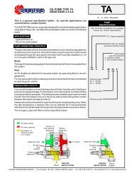
LENOX low NOx burners<br />
Lenox is designed for power plant boilers fulfi lling the stringent<br />
emission requirements. This achievement of technology<br />
is based on staged combustion. Fuel is lead into different<br />
zones of the fl ame. Combustion air is divided into individually<br />
controlled chambers in wind box <strong>and</strong> directed also in<br />
stages to the fl ame. These fuel <strong>and</strong> air fl ows cause optimal<br />
air envelopes inside <strong>and</strong> around the fl ame resulting in long<br />
residence time <strong>and</strong> low emissions. If the requirements of<br />
emission levels are very dem<strong>and</strong>ing, fl ue gas recirculation is<br />
an option to Lenox.<br />
Maximum pressure loss 2.5 kPa.<br />
KT-..L = light fuel oil burner<br />
RT-..L = heavy fuel oil burner<br />
GT-..L = gas burner<br />
GKT-..L = gas/light fuel oil burner<br />
GRT-..L = gas/heavy fuel oil burner<br />
C<br />
10<br />
øB<br />
Ei<br />
øH<br />
20∞<br />
K1 (type GT- ...L)<br />
K2 (type RT- ...L, KT- ...L)<br />
K3 (type GRT- ...L, GKT- ...L)<br />
Burner Nominal A B C Di Ei F H K1 K2 K3<br />
capacity Typical<br />
MW mm mm mm mm mm mm mm mm mm mm<br />
GT/RT/KT/GRT/GKT -5L 0.9 - 4.5 535 730 910 260 425 301 500 2400 2650 2650<br />
GT/RT/KT/GRT/GKT -8L 1.4 - 7.0 640 890 970 310 500 381 590 2500 2750 2750<br />
GT/RT/KT/GRT/GKT -12L 2.2 - 11.0 775 1090 1000 395 625 464 700 2650 2900 2900<br />
GT/RT/KT/GRT/GKT -18L 3.2 - 16.0 895 1260 1050 470 750 544 810 2900 3100 3100<br />
GT/RT/KT/GRT/GKT -25L 4.4 - 22.0 1030 1460 1500 530 900 649 940 3250 3350 3350<br />
GT/RT/KT/GRT/GKT -35L 6.2 - 31.0 1175 1680 1600 630 1025 744 1070 3450 3800 3800<br />
GT/RT/KT/GRT/GKT -50L 9.0 - 45.0 1390 2000 1700 785 1200 882 1270 3900 4200 4200<br />
GT/RT/KT/GRT/GKT -70L 12.6 - 63.0 1590 2300 1875 950 1450 999 1430 4200 4650 4650<br />
F<br />
A<br />
Di
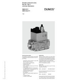
S-burners for a wide range of applications<br />
S-burner is typically used in hot water <strong>and</strong> steam boilers, but<br />
is suitable also in various further applications. The amount<br />
<strong>and</strong> ratio of primary <strong>and</strong> secondary air can be adjusted.<br />
Secondary air is guided through adjustable air vanes, which<br />
enables the formation of the desired fl ame shape <strong>and</strong> thus<br />
matching optimally to the furnace dimensions. Additionally,<br />
the adjustability contributes to achieving the required emission<br />
levels in different furnace sizes <strong>and</strong> forms. By request,<br />
S-burner is capable to be provided<br />
with single or dual-fuel liquid lance,<br />
gas lance <strong>and</strong> gas ring.<br />
Maximum pressure loss 3.5 kPa.<br />
KT-…S = light fuel oil burner<br />
RT-…S = heavy fuel oil burner<br />
GT-…S = gas burner<br />
GKT-…S = gas/light fuel oil burner<br />
GRT-…S = gas/heavy fuel oil burner<br />
<br />
<br />
<br />
<br />
<br />
<br />
<br />
<br />
Burner Nominal A B C Di Ei F H K1 K2 K3<br />
capacity Typical<br />
MW mm mm mm mm mm mm mm mm mm mm<br />
GT/RT/KT/GRT/GKT -5S 0.9 - 4.5 390 735 740 260 425 244 520 1700 2100 2700<br />
GT/RT/KT/GRT/GKT -8S 1.4 - 7.0 460 865 795 310 500 289 600 1900 2300 2900<br />
GT/RT/KT/GRT/GKT -12S 2.2 - 11.0 540 995 865 395 625 327 710 2100 2500 3300<br />
GT/RT/KT/GRT/GKT -18S 3.2 - 16.0 586 1155 980 470 750 335 820 2700 2900 3500<br />
GT/RT/KT/GRT/GKT -25S 4.4 - 22.0 739 1315 1100 530 900 454 940 2600 2900 4000<br />
GT/RT/KT/GRT/GKT -35S 6.2 - 31.0 853 1610 1250 630 1025 530 1030 2900 3500 4300<br />
GT/RT/KT/GRT/GKT -50S 9.0 - 45.0 1024 1750 1300 785 1200 610 1220 3250 3500 4650<br />
<br />
<br />
<br />
5
6<br />
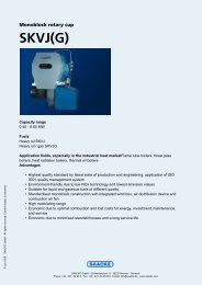
K-burners for various processes<br />
K-burner is the right choice for many different types of<br />
industrial processes, for example in hazardous waste <strong>and</strong><br />
municipal waste incineration plants. The combustion air inlet<br />
is located eccentric on one side of the burner guiding<br />
the combustion air tangentially to the wind box, which<br />
causes a strong swirl <strong>and</strong> stable fl ame. The burner<br />
construction is designed for heavy duty operation to<br />
guarantee good availability in extreme process<br />
conditions. K-burner can be equipped with several<br />
lances according to the number of different fuels.<br />
Maximum pressure loss 3.5 kPa.<br />
KT-…K = light fuel oil burner<br />
RT-…K = heavy fuel oil burner<br />
GT-…K = gas burner<br />
GKT-…K = gas/light fuel oil burner<br />
GRT-…K = gas/heavy fuel oil burner<br />
<br />
<br />
<br />
<br />
<br />
<br />
Burner Nominal A B C Di Ei Fx Fr H K1 K2 K3<br />
capacity Typical<br />
MW mm mm mm mm mm mm mm mm mm mm mm<br />
GT/RT/KT/GRT/GKT -3K 0.5 - 2.7 430 520 600 230 155 210 128 500 2050 2400 2900<br />
GT/RT/KT/GRT/GKT -5K 0.9 - 4.5 550 640 750 295 190 270 170 580 2150 2500 3100<br />
GT/RT/KT/GRT/GKT -8K 1.4 - 7.0 690 780 825 250 375 340 210 670 2400 2700 3300<br />
GT/RT/KT/GRT/GKT -12K 2.2 - 11.0 840 930 900 305 455 415 258 770 2800 2950 3550<br />
GT/RT/KT/GRT/GKT -18K 3.2 - 16.0 1020 1110 970 370 555 505 315 900 3200 3500 4300<br />
GT/RT/KT/GRT/GKT -25K 4.4 - 22.0 1200 1290 1050 450 675 595 365 1030 3700 3900 4900<br />
GT/RT/KT/GRT/GKT -35K 6.2 - 31.0 1410 1510 1150 540 820 700 430 1170 4100 4500 5500
Lance burners especially for<br />
fl uidized bed boilers<br />
Lance burner presents technology to different dem<strong>and</strong>ing<br />
industrial purposes, for example as start-up <strong>and</strong><br />
support burner in fl uidized bed boilers. It is essential,<br />
that the parts will tolerate the effects of the s<strong>and</strong> bed.<br />
This is achieved in lance burner by optimized cleaning<br />
<strong>and</strong> cooling air fl ow through the burner. When the<br />
burner is st<strong>and</strong>-by, the critical parts will be retracted<br />
automatically. The small diameter of the lance burner<br />
allows to minimize burner openings on the boiler walls.<br />
Maximum pressure loss 2.5 kPa.<br />
KL-… = light fuel oil burner<br />
RL-… = heavy fuel oil burner<br />
GL-… = gas burner<br />
GKL-… = gas/light fuel oil burner<br />
GRL-… = gas/heavy fuel oil burner<br />
øB<br />
Ei<br />
C<br />
10<br />
øH<br />
K1 (type GL-<br />
K2 ...) (type RL-... KL-...)<br />
K3 (type GRL-... GKL-...)<br />
Burner Nominal A B C Di Ei Fx H I K1 K2 K3<br />
capacity Typical<br />
MW mm mm mm mm mm mm mm mm mm mm mm<br />
GL/RL/KL -250 1.6 - 6.5 550 550 600 250 375 270 250 1603 3500 3800 N.A.<br />
GL/RL/KL/GRL/GKL-350 3.1 - 12.5 570 660 700 370 555 280 350 1623 4000 4500 4900<br />
GL/RL/KL/GRL/GKL -450 5.3 - 21.0 720 810 800 450 675 355 450 1982 4700 5100 5600<br />
GL/RL/KL/GRL/GKL -550 7.8 - 31.0 820 960 890 540 820 405 550 2082 5300 5700 6200<br />
F<br />
Di<br />
A<br />
I<br />
7
8<br />
Auxiliary equipment<br />
Correctly dimensioned <strong>and</strong> designed auxiliary equipment is<br />
essential to guarantee optimal performance of the burner.<br />
The right instruments, piping materials <strong>and</strong> process values are<br />
chosen on the basis of long experience. All the equipment is<br />
assembled <strong>and</strong> tested at factory <strong>and</strong> includes the necessary<br />
wiring <strong>and</strong> instrument piping.<br />
Valve units<br />
for process gases<br />
The nature <strong>and</strong> amount of process gases<br />
vary considerably depending on the process<br />
in question. Corrosive gases, dem<strong>and</strong>ing<br />
conditions <strong>and</strong> surroundings etc. are<br />
taken into account.<br />
Valve units for<br />
natural gas<br />
The capacity of shut-off valve units<br />
varies in a range of 200-6500 m³n/<br />
h/burner. <strong>Filter</strong>ing, measuring <strong>and</strong><br />
controlling unit can be individual for<br />
each burner. The multi-burner installations,<br />
however, can be provided<br />
with a unit common for all burners<br />
or burner groups.
Rack of three shut-off valve units.<br />
Oil pumping units<br />
The pumping units include fi ltering, pumping <strong>and</strong> pre-heating<br />
functions, according to the need. In order to reach high<br />
availability, the st<strong>and</strong>ard solution is realized with two identical<br />
lines. In case of high viscosity, the fuel will be heated<br />
up to the correct viscosity by means of steam. For the cold<br />
start-up of the plant the pumping units can be equipped<br />
with electrical heat exchanger.<br />
Valve units for oils <strong>and</strong><br />
other liquid fuels<br />
The shut-off valve unit range covers<br />
capacities 150-6000 kg/h/burner.<br />
Units can be assembled into one<br />
common rack. It is also possible to<br />
combine several different fuels.<br />
9
10<br />
Burner management systems<br />
Oilon has a long experience in designing <strong>and</strong> manufacturing<br />
Burner Management Systems (BMS) to combustion<br />
processes. BMS of Oilon utilize optimized controls ensuring<br />
the right sequence <strong>and</strong> fi ne tuned timing. Consequently,<br />
the optimized performance of the combustion means high<br />
effi ciency <strong>and</strong> low emissions.<br />
For typical solutions there are st<strong>and</strong>ard BMS packages available<br />
<strong>and</strong> for each specifi c requirement customized systems<br />
are worked out. The extent of the system is to be agreed<br />
case by case. Normally BMS will be implemented in the main<br />
control system of the <strong>Plant</strong> (DCS). BMS can be based on<br />
Programmable Logic Control (PLC) or control relay system.<br />
Safety <strong>and</strong> availability are in important role while designing<br />
<strong>and</strong> realizing an automation system. The right safety level<br />
<strong>and</strong> the need for redundant system will be determined to<br />
meet the requirements of the whole process. Every BMS is<br />
factory tested (FAT) to guarantee smooth <strong>and</strong> fast start-up<br />
of the combustion system in the plant.<br />
BMS with touch panel for four burners.<br />
BMS safety devices. Touch panel screen for combustion system.
Oilon invests in product development <strong>and</strong><br />
research. A modern product development centre<br />
meeting all European st<strong>and</strong>ards enables us to<br />
perform a wide range of combustion tests <strong>and</strong><br />
accurate oil <strong>and</strong> gas measurements.<br />
Computational fl uid dynamics (CFD) is an essential<br />
part of our research <strong>and</strong> product development.<br />
3D-design <strong>and</strong> CFD support each other in making<br />
decisions on the optimal burner structures. Flow<br />
profi les <strong>and</strong> pressure losses of combustion air,<br />
emission levels <strong>and</strong> temperature distribution in<br />
the furnace can also be determined<br />
OILON ENERGY OY<br />
Metsä-Pietilänkatu 1<br />
P.O. Box 5<br />
FI-15801 Lahti, Finl<strong>and</strong><br />
Tel. +358 3 85 761<br />
Fax +358 3 857 6277<br />
info@oilon.com<br />
www.oilon.com<br />
GB6/1.00/102006