MFP14 Automatic Pumps for Condensate and other Industrial ... - Filter
MFP14 Automatic Pumps for Condensate and other Industrial ... - Filter
MFP14 Automatic Pumps for Condensate and other Industrial ... - Filter

You also want an ePaper? Increase the reach of your titles
YUMPU automatically turns print PDFs into web optimized ePapers that Google loves.
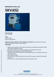
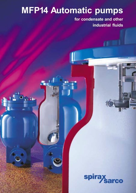
<strong>MFP14</strong> <strong>Automatic</strong> pumps<br />
<strong>for</strong> condensate <strong>and</strong> <strong>other</strong><br />
industrial fluids
2<br />
Effective condensate management ...<br />
an essential part of any steam plant<br />
If energy requirements are to be kept to a minimum, then efficient h<strong>and</strong>ling of condensate is<br />
essential to optimise plant efficiency <strong>and</strong> product quality.<br />
Spirax Sarco offers the solutions to achieve this efficiency in all areas of condensate pumping.<br />
<strong>Condensate</strong> Management covers two separate key areas:<br />
<strong>Condensate</strong> recovery<br />
When condensate leaves the steam trap it has<br />
approximately 20 % of the original heat energy<br />
contained within the steam.<br />
Recovering <strong>and</strong> returning this valuable energy source<br />
saves:<br />
Heat energy - saving fuel.<br />
Expensive water treatment chemicals.<br />
High feedwater make-up costs.<br />
All too often these problems have been neglected<br />
because no fully engineered system was readily<br />
available.<br />
Stainless steel cover bolts.<br />
High integrity trapped<br />
cover gasket.<br />
Replaceable valves <strong>and</strong> seats.<br />
Pump cycle counter available<br />
enabling the volume of<br />
pumped fluid to be calculated.<br />
Available with optional<br />
custom insulation jacket.<br />
Available with DIN PN16,<br />
ANSI 150, JIS/KS 10 or<br />
screwed boss flanges.<br />
Lifting eye.<br />
Low level drain point.<br />
<strong>Condensate</strong> removal<br />
<strong>Condensate</strong> removal from all heat exchange <strong>and</strong><br />
process equipment is necessary to provide stable<br />
operating conditions, giving improved efficiency<br />
<strong>and</strong> prolonging equipment life.<br />
Efficient condensate removal prevents:<br />
Unstable temperature control.<br />
Product quality problems.<br />
Excessive corrosion of heating surfaces.<br />
Waterhammer.<br />
Noisy operation.<br />
Equipment damage.<br />
Available with screwed BSP,<br />
NPT or socket weld motive<br />
fluid connections.<br />
The <strong>MFP14</strong> is available in a<br />
wide variety of materials:-<br />
SG iron <strong>MFP14</strong><br />
Cast steel <strong>MFP14</strong>S<br />
Cast stainless steel <strong>MFP14</strong>SS<br />
Body <strong>and</strong> cover 3.1.B<br />
certifiable <strong>and</strong> available with<br />
TÜV approval.<br />
Stainless steel<br />
internal mechanism.<br />
Robust stainless steel float.<br />
Stainless steel high capacity<br />
inlet <strong>and</strong> outlet check valves.
The total solution<br />
Spirax Sarco’s range of <strong>MFP14</strong> automatic pumps<br />
are specifically designed to remove <strong>and</strong> recover<br />
condensate under all operating conditions <strong>and</strong><br />
provide the unique opportunity to solve all<br />
condensate h<strong>and</strong>ling problems.<br />
The pumps are self-contained units using steam or<br />
<strong>other</strong> pressurised gas as their motive power.<br />
There are no electric motors or level switches,<br />
simplifying installation <strong>and</strong> making it ideal<br />
<strong>for</strong> hazardous areas.<br />
One pump design covers all applications from<br />
vacuum systems to general condensate return.<br />
<strong>MFP14</strong> automatic pumps are able to pump high<br />
temperature fluids without cavitation, reducing plant<br />
maintenance problems. They are also well suited<br />
to pump <strong>other</strong> industrial fluids including<br />
contaminated water, oils, <strong>and</strong> some<br />
hydrocarbon condensates.<br />
Size<br />
Inlet / Outlet<br />
Connections<br />
Motive fluid<br />
Connections<br />
Range <strong>and</strong> options<br />
User benefits<br />
● Removes condensate under all load<br />
conditions, even vacuum, ensuring<br />
maximum process efficiency.<br />
● Requires no electrical power -<br />
suitable <strong>for</strong> hazardous environments.<br />
● Cavitation problems eliminated<br />
reducing maintenance.<br />
● No mechanical seals or packing gl<strong>and</strong>s to leak.<br />
● Effective design provides high capacity<br />
in a rugged, compact package.<br />
● Available in a range of materials, sizes <strong>and</strong> end<br />
connections to suit a wide variety of applications.<br />
● Can be supplied with TÜV approval.<br />
● Spirax Sarco's guarantee of worldwide<br />
technical support, knowledge <strong>and</strong> service.<br />
Material SG iron Steel Stainless steel<br />
Pump type <strong>MFP14</strong> <strong>MFP14</strong>S <strong>MFP14</strong>SS<br />
Body material<br />
SG iron<br />
DIN GGG 40.3<br />
Steel<br />
DIN GSC 25N /<br />
ASTM A216 WCB<br />
Stainless steel<br />
DIN 1.4409 /<br />
ASTM A351 CF3M<br />
Body design rating PN16 PN16 PN16<br />
DN25 1" ●<br />
DN40 1½" ●<br />
DN50 2" ● ●<br />
DN80 inlet 3" inlet<br />
DN50 outlet 2" outlet ● ● ●<br />
PN16 ● ● ●<br />
Flanged ANSI 150 ● ● ●<br />
JIS / KS 10 ● ● ●<br />
Screwed BSP ● ● ●<br />
Screwed<br />
BSP<br />
NPT<br />
●<br />
●<br />
●<br />
●<br />
●<br />
●<br />
Socket weld ● ●<br />
Stainless steel internal mechanism ● ● ●<br />
Maximum operating pressure 13.8 bar g<br />
Maximum operating temperature 200°C<br />
Nominal capacity with 8 bar g operating pressure <strong>and</strong> 1 bar g back pressure<br />
DN25 DN40 DN50 DN80 inlet x DN50 outlet<br />
1" 1½" 2" 3" inlet x 2" outlet<br />
1 100 kg/h 1 800 kg/h 3 800 kg/h 5 500 kg/h<br />
3
4<br />
How the <strong>MFP14</strong> works<br />
The <strong>MFP14</strong> automatic pump operates on a positive<br />
displacement principle.<br />
Fluid enters the pump body through the inlet check valve<br />
1 causing the float to rise.<br />
Residual non-condensibles in the body escape through<br />
2 the open exhaust valve, Fig 1. As the chamber fills, the<br />
valve change over linkage is engaged opening the motive inlet<br />
valve <strong>and</strong> closing the exhaust valve, Fig 2. This snap action<br />
linkage ensures a rapid change from filling to pumping stroke.<br />
As pressure inside the pump increases above the<br />
3 total back pressure, fluid is <strong>for</strong>ced out through the outlet<br />
check valve into the return system.<br />
As the fluid level falls within the pump, the float<br />
4 re-engages the valve change over linkage causing the<br />
motive inlet valve to close <strong>and</strong> the exhaust valve to open.<br />
As the pressure inside the pump body falls, fluid<br />
5 re-enters through the inlet check valve <strong>and</strong> the cycle<br />
is repeated.<br />
Figure 1. Filling stroke<br />
Motive exhaust<br />
outlet<br />
open<br />
Lifting eye.<br />
Figure 2.<br />
Discharge<br />
stroke<br />
Motive inlet open<br />
Fluid in Fluid out<br />
Inlet check valve<br />
Outlet check valve
<strong>Condensate</strong> recovery (open system)<br />
Pumping high temperature condensate without<br />
cavitation or mechanical seal problems.<br />
Provides maximum heat energy recovery.<br />
* A soft seated check valve should be fitted<br />
to prevent ingress of air<br />
<strong>Condensate</strong> collecting receiver<br />
Pump<br />
Typical applications<br />
*<br />
Air<br />
vent<br />
Float<br />
trap<br />
<strong>Condensate</strong><br />
collecting<br />
receiver<br />
Pump<br />
Heat exchanger<br />
<strong>Condensate</strong> removal from process vessels <strong>and</strong> heat exchangers<br />
(pump/trap combination, closed system)<br />
Removal of condensate under all pressure conditions ensures stable temperatures.<br />
It also prevents bottom end tube corrosion <strong>and</strong> potential waterhammer <strong>and</strong> freezing.<br />
Float trap<br />
Vacuum heat<br />
exchanger / receiver<br />
Pump<br />
Float<br />
trap<br />
<strong>Condensate</strong> removal from<br />
vacuum equipment<br />
Simple <strong>and</strong> efficient solution to a difficult problem<br />
without the need <strong>for</strong> expensive electrical pumps<br />
<strong>and</strong> sensors.<br />
5
6<br />
How to size <strong>and</strong><br />
select the <strong>MFP14</strong><br />
Considering the inlet pressure, back pressure <strong>and</strong><br />
filling head conditions, select the pump size which<br />
meets the capacity requirements of the application.<br />
Plant<br />
1 500 kg/h<br />
0.15m<br />
Filling head<br />
Reservoir<br />
<strong>MFP14</strong><br />
P2 = 1.7barg<br />
Return main<br />
pressure <strong>and</strong><br />
pipe length<br />
Operating<br />
pressure<br />
5.2 bar g<br />
The known data<br />
<strong>Condensate</strong> load 1 500 kg/h<br />
Steam pressure available <strong>for</strong> operating pump 5.2 bar g<br />
Vertical lift from pump to the return piping 9.2 m<br />
Pressure in the return piping (piping friction negligible) 1.7 bar g<br />
Filling head on the pump available 0.15 m<br />
Selection example<br />
Final pump selection<br />
Lift = 9.2m<br />
Firstly calculate the total effective lift against which<br />
condensate must be pumped.<br />
Total effective lift is calculated by adding vertical lift from<br />
the pump to return piping (9.2 m) to the pressure in the<br />
return piping (1.7 bar g). To convert pressure in<br />
the return pipe into pressure head, divide it by the<br />
conversion factor of 0.0981:-<br />
P2 = 1.7 bar g ÷ 0.0981 = 17.3 m Pressure head (lift)<br />
The total effective lift then becomes calculable :-<br />
9.2 m + 17.3 m<br />
The total effective lift is 26.5 m.<br />
Now that the total effective lift has been calculated, a pump<br />
can be selected by plotting the known data onto the graphs<br />
opposite.<br />
1.Plot a horizontal line from 5.2 bar g (Motive pressure).<br />
2.Plot a line indicating 26.5 m lift.<br />
3.From the point where the motive pressure line crosses<br />
the m lift line, drop a vertical line to the X axis.<br />
4.Read the corresponding capacity (2 500 kg/ h).<br />
Note: As the filling head is different to 0.3 m, then the<br />
capacity calculated above must be corrected by the<br />
appropriate factor selected from the table below.<br />
Capacity multiplying factors <strong>for</strong> <strong>other</strong> filling heads<br />
Filling head Capacity multiplying factors<br />
metres (m) DN25 DN40 DN50 DN80 x DN50<br />
0.15 0.90 0.75 0.75 0.80<br />
0.30 1.00 1.00 1.00 1.00<br />
0.60 1.15 1.10 1.20 1.05<br />
0.90 1.35 1.25 1.30 1.15<br />
For motive fluids <strong>other</strong> than steam, see the relevant technical in<strong>for</strong>mation sheet<br />
The size of pump selected in this case would be DN50.<br />
This has the capability to pump:-<br />
0.75 x 2 500 kg/ h = 1 875 kg/ h<br />
easily coping with a condensate load of 1 500 kg/h.<br />
Motive pressure bar g<br />
Motive pressure bar g<br />
14<br />
12<br />
10<br />
8<br />
6<br />
4<br />
2<br />
0<br />
0 400 800 1 200 1 600 2 000<br />
DN40 (1½")<br />
Flowrate kg / h<br />
Motive pressure bar g<br />
DN50 (2")<br />
Motive pressure bar g<br />
14<br />
12<br />
10<br />
8<br />
6<br />
4<br />
2<br />
DN25 (1")<br />
14<br />
12<br />
10<br />
8<br />
6<br />
4<br />
2<br />
0<br />
14<br />
12<br />
10<br />
8<br />
6<br />
4<br />
2<br />
Capacity charts<br />
The capacity charts are based on a filling head of 0.3 meters.<br />
The lift lines represent the net effective lift<br />
(i.e. lift plus frictional resistance)<br />
0 0 200 400 600 800 1 000 1 200<br />
1 000 2 000 3 000 4 000 5 000<br />
80 m lift<br />
80 m lift<br />
50 m lift<br />
50 m lift<br />
0 1 000 2 000 3 000 4 000 5 000 6 000<br />
DN80 x DN50 (3"x 2")<br />
40 m lift<br />
40 m lift<br />
80 m lift<br />
30 m lift<br />
26.5 m lift<br />
30 m lift<br />
80 m lift<br />
50 m lift<br />
40 m lift<br />
20 m lift<br />
50 m lift<br />
40 m lift<br />
30 m lift<br />
20 m lift<br />
10 m lift<br />
30 m lift<br />
20 m lift<br />
10 m lift<br />
10 m lift<br />
4 m lift<br />
10 m lift<br />
4 m lift<br />
4 m lift 4 m lift<br />
Flowrate kg / h<br />
20 m lift<br />
Flowrate kg / h<br />
Flowrate kg / h
<strong>Condensate</strong> removal<br />
from temperature controlled equipment<br />
The operation of temperature controls on plant equipment such<br />
as heat exchangers can create a 'Stall' condition whereby the<br />
condensate cannot flow through the steam trap because of<br />
insufficient differential pressure.<br />
Under stall conditions partial or complete waterlogging may<br />
occur leading to :-<br />
Temperature fluctuation.<br />
Corrosion of heating surfaces.<br />
Waterhammer, noise <strong>and</strong> damage.<br />
By constructing a simple stall chart (as example opposite),<br />
it is possible to predict the point at which stall will occur <strong>and</strong><br />
hence determine the conditions at which waterlogging will<br />
begin.<br />
T1 represents the minimum incoming secondary fluid<br />
temperature when the plant is under 100 % load.<br />
T2 represents the controlled outgoing secondary<br />
fluid temperature.<br />
P1 represents the controlled pressure of the steam<br />
when the plant is under 100 % load (corresponding<br />
temperature on the left h<strong>and</strong> axis).<br />
P2 represents the back pressure acting on the trap.<br />
R1 is a vertical line drawn from the point at which<br />
P1-T2 intersects P2.<br />
The percentage load at which the system is predicted to<br />
stall can be determined where R1 touches the X-axis.<br />
The incoming secondary fluid temperature at which the<br />
system is predicted to stall can be determined where R1<br />
intersects T1-T2, the horizontal line R2 will give this value.<br />
Steam supply<br />
<strong>MFP14</strong><br />
Temperature control<br />
Float type steam trap<br />
Heat exchanger<br />
<strong>Condensate</strong><br />
return line<br />
Temperature °C<br />
200<br />
180<br />
160<br />
140<br />
120<br />
100<br />
80<br />
60<br />
40<br />
20<br />
P 1<br />
Normal<br />
condensate<br />
removal<br />
R 2<br />
T 1<br />
Stall chart<br />
R 1<br />
Percentage load<br />
Steam space<br />
waterlogged<br />
P2 T1 The solution<br />
Spirax Sarco’s range of <strong>MFP14</strong> automatic pump/<br />
trap combinations provide the total solution to<br />
stall conditions. By mounting the steam trap<br />
immediately downstream of the pump (between<br />
the pump outlet <strong>and</strong> the downstream check<br />
valve) condensate can be removed under all<br />
pressure conditions.<br />
When the steam space pressure is sufficient to<br />
overcome the total back pressure (including<br />
static lift) the trap will operate normally.<br />
When the steam space pressure falls below the<br />
total back pressure, the pump automatically trips<br />
into operation <strong>and</strong> <strong>for</strong>ces all the condensate out<br />
through the trap be<strong>for</strong>e waterlogging can occur.<br />
This pump/trap combination enables optimum<br />
per<strong>for</strong>mance to be achieved from all types of<br />
temperature controlled process equipment. See<br />
your local Spirax Sarco sales engineer <strong>for</strong><br />
further details on how a Spirax Sarco pump/<br />
trap combination could improve the per<strong>for</strong>mance<br />
of your process equipment.<br />
P 2<br />
0<br />
100 90 80 70 60 50 40 30 20 10 0<br />
P 1<br />
T 2<br />
T 2<br />
14.5<br />
11.6<br />
9.0<br />
7.0<br />
5.2<br />
3.8<br />
2.6<br />
1.7<br />
1.0<br />
0.4<br />
0<br />
0.7<br />
0.5<br />
0.3<br />
0.2<br />
0.1<br />
0.05<br />
Pressure bar absolute (vacuum) Pressure bar gauge<br />
7
Withdrawal distance H<br />
<strong>MFP14</strong><br />
SG iron<br />
<strong>MFP14</strong>S<br />
Steel<br />
<strong>MFP14</strong>SS<br />
Stainless<br />
steel<br />
E<br />
Dimensions (approximate in millimetres)<br />
B<br />
A<br />
G<br />
F<br />
Size A B C D E F G H Weight (kg)*<br />
DN25 1" 410 310 510 280 72 72 22 480 58<br />
DN40 1½" 440 310 530 280 85 85 22 480 63<br />
DN50 2" 557 420 627 321 104 104 22 580 82<br />
DN80 x DN50<br />
3" x 2"<br />
573 420 627 321 119 104 22 580 86<br />
Size A B C D E F G H Weight (kg)*<br />
DN50 2" 557 420 627 321 104 104 22 580 100<br />
DN80 x DN50<br />
3" x 2"<br />
573 420 627 321 119 104 22 580 105<br />
Size A B C D E F G H Weight (kg)*<br />
DN80 x DN50<br />
3" x 2"<br />
573 420 627 321 119 104 22 580 105<br />
Some of the products may not be available in certain markets.<br />
C<br />
Collar eyebolt 15 mm eye diameter<br />
D<br />
*Weights inclusive of check valves <strong>and</strong> flanges<br />
Typical specification<br />
The pump shall be a Spirax Sarco automatic pump type <strong>MFP14</strong> operated by steam, compressed air or <strong>other</strong><br />
pressurised gas to 13.8 bar g. No electrical energy shall be required.<br />
Body construction of SG iron (DIN 1693, GGG 40.3) with disc type check valves <strong>for</strong> pumping liquids of specific<br />
gravity of 0.8 <strong>and</strong> above. The pump shall contain a float operated stainless steel snap-action mechanism with no<br />
external seals or packing. When required, it should be fitted with a custom insulation jacket <strong>for</strong> maximum energy<br />
saving <strong>and</strong> a cycle counter to enable the volume of pumped liquid to be calculated.<br />
Spirax-Sarco Limited, Charlton House,<br />
Cheltenham, Gloucestershire, GL53 8ER UK.<br />
Tel: +44 (0)1242 521361 Fax: +44 (0)1242 573342<br />
E-mail: Enquiries@SpiraxSarco.com<br />
Internet: www.SpiraxSarco.com<br />
© Copyright 2000 Spirax Sarco is a registered trademark of Spirax-Sarco Limited<br />
SB-P136-01 ST Issue 6<br />
MFP