95% Gas Furnaces - 2 Stage - Fox Appliance Parts of Macon, Inc.
95% Gas Furnaces - 2 Stage - Fox Appliance Parts of Macon, Inc.
95% Gas Furnaces - 2 Stage - Fox Appliance Parts of Macon, Inc.

Create successful ePaper yourself
Turn your PDF publications into a flip-book with our unique Google optimized e-Paper software.
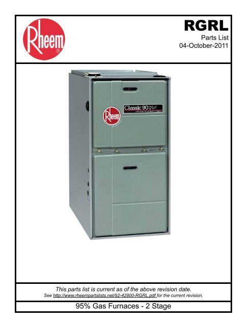
This parts list is current as <strong>of</strong> the above revision date.<br />
See http://www.rheempartslists.net/92-42800-RGRL.pdf for the current revision.<br />
<strong>95%</strong> <strong>Gas</strong> <strong>Furnaces</strong> - 2 <strong>Stage</strong><br />
RGRL<br />
<strong>Parts</strong> List<br />
04-October-2011
Table <strong>of</strong> Contents<br />
Model Explanation . . . . . . . . . . . . . . . . . . . . . . . . . . . . . . . . . . . . . . . . . . . . . . . . . . . . . . . . . . . . . . . . . . . Page 3<br />
<strong>Parts</strong> Numbers<br />
Panels - Miscellaneous. . . . . . . . . . . . . . . . . . . . . . . . . . . . . . . . . . . . . . . . . . . . . . . . . . Page 4<br />
Electrical Group . . . . . . . . . . . . . . . . . . . . . . . . . . . . . . . . . . . . . . . . . . . . . . . . . . . . . . . . . Page 5<br />
Blower Group . . . . . . . . . . . . . . . . . . . . . . . . . . . . . . . . . . . . . . . . . . . . . . . . . . . . . . . . . . . Page 5<br />
Heat Exchanger-Burner Group . . . . . . . . . . . . . . . . . . . . . . . . . . . . . . . . . . . . . . . . . . Page 6<br />
<strong>Gas</strong> Controls. . . . . . . . . . . . . . . . . . . . . . . . . . . . . . . . . . . . . . . . . . . . . . . . . . . . . . . . . . . . Page 6<br />
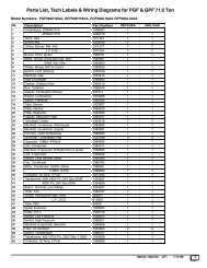
Orifice Selection Chart . . . . . . . . . . . . . . . . . . . . . . . . . . . . . . . . . . . . . . . . . . . . . . . . . . Page 7<br />
Drawings/Photographs<br />
Exploded View . . . . . . . . . . . . . . . . . . . . . . . . . . . . . . . . . . . . . . . . . . . . . . . . . . . . . . . . . . Page 8<br />
Blower Assembly. . . . . . . . . . . . . . . . . . . . . . . . . . . . . . . . . . . . . . . . . . . . . . . . . . . . . . . . Page 9<br />
Burner Assembly. . . . . . . . . . . . . . . . . . . . . . . . . . . . . . . . . . . . . . . . . . . . . . . . . . . . . . . Page 10<br />
Notes/Disclaimer . . . . . . . . . . . . . . . . . . . . . . . . . . . . . . . . . . . . . . . . . . . . . . . . . . . . . . . . . . . . . . . . . . . . Page 11<br />
Page 2 <strong>of</strong> 11<br />
04-October-2011<br />
92-42800-RGRL
MODEL NUMBER EXPLANATION<br />
R G R L - 0 4 E M A E S 278<br />
(1) (2) (3) (4) (5) (6) (7) (8) (9) (10)<br />
(1) TRADEBRAND IDENTIFICATION (7) VARIATIONS<br />
A = Standard<br />
(2) MODEL<br />
G = <strong>Gas</strong> Furnace<br />
B = Wide Cabinet<br />
(8) AIRFLOW<br />
(3) TYPE E = 1100-1300 CFM<br />
R = Upflow Condensing G = 1500-1700 CFM<br />
J = 1900-2100 CFM<br />
(4) DESIGN SERIES<br />
(9) FUEL DESIGNATION<br />
(5) HEATING INPUT DESIGNATION S = Natural <strong>Gas</strong><br />
Electric<br />
NOX Input BTU/HR<br />
Ignition<br />
04E 04N = 45,000 (10) OPTION CODE<br />
06E 06N = 60,000<br />
07E 07N = 75,000<br />
09E 09N = 90,000<br />
10E 10N = 105,000<br />
(6) BLOWER DESIGNATION<br />
M = 11 x 7<br />
R = 11 x 10<br />
Y = 12 x 7<br />
Z = 12 x 11<br />
SERIAL NUMBER EXPLANATION<br />
G T 5 D 7 0 7 F 3 1 0 3 9 9 9 9<br />
(1) (2) (3) (4) (5) (6) (7) (8) (9) (10)<br />
(1) GAS CODE (6) MOTOR HORSEPOWER<br />
(2) LIMIT CONTROL (7) PLANT<br />
F = Fort Smith, AR<br />
(3) BLOWER<br />
(8) WEEK<br />
(4) HEATING ELEMENT<br />
(9) YEAR<br />
(5) SPECIAL AREA REQUIREMENT<br />
(10) PRODUCTION NUMBER<br />
Page 3 <strong>of</strong> 11<br />
04-October-2011<br />
92-42800-RGRL
MODEL<br />
RGRL RGRL RGRL RGRL RGRL RGRL<br />
HEATING CAPACITY<br />
04<br />
06<br />
07<br />
07<br />
09<br />
10<br />
No. Notes BLOWER DESIGNATION<br />
M<br />
M<br />
M<br />
Y<br />
Z<br />
Z<br />
VARIATION<br />
A<br />
A<br />
A<br />
B<br />
A<br />
A<br />
AIRFLOW<br />
E<br />
E<br />
E<br />
G<br />
J<br />
J<br />
PANELS, SHEET METAL, MISCELLANEOUS<br />
1 Jacket AS-61824-25 AS-61824-25 AS-61824-25 AS-61824-27 AS-61824-26 AS-61824-26<br />
4 5 Outlet Air Pipe 68-24021-01 68-24021-01 68-24021-01<br />
68-24021-01<br />
(See Note 5)<br />
68-24021-01 68-24021-01<br />
5 <strong>Gas</strong>ket - Outlet Air Pipe 68-24022-02 68-24022-02 68-24022-02 68-24022-02 68-24022-02 68-24022-02<br />
6 Top Plate AS-61872-01 AS-61872-01 AS-61872-01 AS-61872-02 AS-61872-02 AS-61872-02<br />
7 Locknut - Fresh Air Damper 64-24031-01 64-24031-01 64-24031-01 64-24031-01 64-24031-01 64-24031-01<br />
8 Burner Door AS-61905-01 AS-61905-01 AS-61905-01 AS-61906-01 AS-61906-01 AS-61906-01<br />
9 Blower/Filter Door AS-61908-03 AS-61908-03 AS-61908-03 AS-61909-03 AS-61909-03 AS-61909-03<br />
10 Filter - Plastic 54-24094-01 54-24094-01 54-24094-01 54-24094-02 54-24094-02 54-24094-02<br />
Filter Retainer Rod 45-24095-01 45-24095-01 45-24095-01 45-24095-01 45-24095-01 45-24095-01<br />
Filter Rod Support Angle AE-60520-01 AE-60520-01 AE-60520-01 AE-60520-01 AE-60520-01 AE-60520-01<br />
Filter Support Angle AE-61883-01 AE-61883-01 AE-61883-01 AE-61883-01 AE-61883-01 AE-61883-01<br />
11 Solid Bottom AE-61874-02 AE-61874-02 AE-61874-02 AE-61874-03 AE-61874-03 AE-61874-03<br />
Button Plug - 1-5/8 in. opening 45-22980-02 45-22980-02 N/A N/A 45-22980-02 N/A<br />
Button Plug - 2 in. opening 45-22980-08 45-22980-08 45-22980-08 45-22980-08 45-22980-08 45-22980-08<br />
Button Plug (2) - 2-3/8 in. opening 45-22980-03 45-22980-03 45-22980-03 45-22980-03 45-22980-03 45-22980-03<br />
12 Pressure Switch Assembly See Electrical Group<br />
Silicon Tubing - Pressure Switch AE-61737-10 AE-61737-10 AE-61737-10 AE-61737-10 AE-61737-10 AE-61737-10<br />
13 Trap / Elbow Assembly 68-100651-01 68-100651-01 68-100651-01 68-100651-01 68-100651-01 68-100651-01<br />
14 Water Trap Mount Bracket AE-61841-01 AE-61841-01 AE-61841-01 AE-61841-01 AE-61841-01 AE-61841-01<br />
15 Junction Box Cover AE-61476-02 AE-61476-02 AE-61476-02 AE-61476-02 AE-61476-02 AE-61476-02<br />
16 Door Switch (Push Button) See Electrical Group<br />
17 Junction Box AE-61475-02 AE-61475-02 AE-61475-02 AE-61475-02 AE-61475-02 AE-61475-02<br />
Grommet (5/8 in. Tube) 56-22521-03 56-22521-03 56-22521-03 56-22521-03 56-22521-03 56-22521-03<br />
Grommet (1/2 in. I.D.) 56-24008-01 56-24008-01 56-24008-01 56-24008-01 56-24008-01 56-24008-01<br />
Grommet (1/4 in. I.D.) 56-24008-02 56-24008-02 56-24008-02 56-24008-02 56-24008-02 56-24008-02<br />
Grommet (1-5/8 in. opening) - Before F3906 56-22114-01 56-22114-01 N/A N/A 56-22114-01 N/A<br />
Grommet (2 in. opening) - After F3906 56-22114-06 56-22114-06 56-22114-06 56-22114-06 56-22114-06 56-22114-06<br />
28 Heat Exchanger See Heat Exchanger Group<br />
29 Limit - Main Limit (Heat Exchanger Panel) See Electrical Group<br />
30 5 Connector/Transition 68-24047-07 68-24047-07 68-103061-01 68-24047-13<br />
(See Note 5)<br />
68-24047-08 68-24047-08<br />
31 Induced Draft Blower w/<strong>Gas</strong>ket See Electrical Group<br />
Tubing (1/2 in. I.D.) - <strong>Inc</strong>ludes Two Hose Clamps (3) 79-25353-82 79-25353-82 79-25353-82 79-25353-82 79-25353-82 79-25353-82<br />
Tubing Drain Trap (Induced Draft Blower - <strong>Inc</strong>ludes two<br />
Hose Clamps)<br />
791000 791000 791000 791001 791001 791001<br />
Elbow (Induced Draft Blower - 1/2 in. barbed) 68-24013-01 68-24013-01 68-24013-01 68-24013-01 68-24013-01 68-24013-01<br />
MODEL<br />
RGRL<br />
HEATING CAPACITY<br />
ALL<br />
No. Notes BLOWER DESIGNATION<br />
ALL<br />
VARIATION<br />
ALL<br />
AIRFLOW<br />
ALL<br />
Complete <strong>Parts</strong> Bag<br />
PARTS BAG<br />
AS-100717-01<br />
2 O-Ring - Fresh Air Damper 68-24032-01<br />
3 Adapter - Fresh Air Damper and Locknut 68-24114-01<br />
1/2 in. Tee 68-21980-02<br />
1/2 in. PVC Pipe - 4 in. 68-22024-04<br />
Plug - Nylon - 7/8 in. 45-22926-01<br />
Plug - Nylon 1-1/8 in. 45-22926-02<br />
PVC Vane 68-23473-01<br />
PVC Wind Vane - 2-1/2 in. 68-24049-01<br />
Hose Clamp 64-22043-01<br />
Hose Clamp (2) 64-22043-02<br />
Page 4 <strong>of</strong> 11<br />
04-October-2011<br />
92-42800-RGRL
MODEL<br />
RGRL RGRL RGRL RGRL RGRL RGRL<br />
HEATING CAPACITY<br />
04<br />
06<br />
07<br />
07<br />
09<br />
10<br />
No. Notes BLOWER DESIGNATION<br />
M<br />
M<br />
M<br />
Y<br />
Z<br />
Z<br />
VARIATION<br />
A<br />
A<br />
A<br />
B<br />
A<br />
A<br />
AIRFLOW<br />
E<br />
E<br />
E<br />
G<br />
J<br />
J<br />
12 Stk Pressure Switch Assembly - Before F3010<br />
ELECTRICAL GROUP<br />
42-102056-01 42-102056-06 42-102056-13 42-102056-02 42-102056-03 42-103193-01<br />
12 Stk Pressure Switch Assembly - After F3010 42-102056-01 42-102056-06 42-102056-22 42-102056-02 42-102056-03 42-102056-01<br />
12 Stk Pressure Switch Assembly - Option 278 42-102056-07 42-102056-08 N/A 42-102056-07 42-102056-11 42-102056-10<br />
16 Door Switch (Push Button) 42-22692-02 42-22692-02 42-22692-02 42-22692-02 42-22692-02 42-22692-02<br />
19 Stk Transformer w/Fuse - Before F1106 46-22863-04 46-22863-04 46-22863-04 N/A 46-22863-04 46-22863-04<br />
19 Stk Transformer w/Fuse - After F1106 46-101496-01 46-101496-01 46-22863-04 46-22863-04 46-101496-01 46-22863-04<br />
Fuse - Transformer 46-22863-84 46-22863-84 46-22863-84 46-22863-84 46-22863-84 46-22863-84<br />
21 Integrated Furnace Control Board (IFC) See <strong>Gas</strong> Controls<br />
29 Stk Limit - Main Limit (Heat Exchanger Panel) 47-25350-06 47-25350-05 47-25350-09 47-25350-01 47-25350-01 47-25350-07<br />
34a Stk Limit - Manual Reset (Burner Compartment)<br />
47-22861-02<br />
(1)<br />
47-22861-02<br />
(1)<br />
47-22861-02<br />
(2)<br />
47-22861-02<br />
(2)<br />
47-22861-02<br />
(2)<br />
47-22861-02<br />
(2)<br />
31 Stk,4 Induced Draft Blower w/<strong>Gas</strong>ket 70-100612-03 70-100612-03 70-100612-03 70-100612-03 70-100612-03 70-100612-03<br />
<strong>Gas</strong>ket - Induced Draft Blower 68-24016-01 68-24016-01 68-24016-01 68-24016-01 68-24016-01 68-24016-01<br />
23<br />
Capacitor - Induced Draft Blower (Before F3010) - See<br />
Stk,4<br />
Note 4<br />
43-100496-03 43-100496-03 43-100496-03 43-100496-03 43-100496-03 43-100496-03<br />
23<br />
Capacitor - Induced Draft Blower (After F3010) - See Note<br />
Stk,4<br />
4<br />
43-25134-35 43-25134-35 43-25134-35 43-25134-35 43-25134-35 43-25134-35<br />
Twist Lock Wiring Harnesses - 15 pin to (5 pin/3 pin/6<br />
terminals), 14 wires from 15 pin (Before F3010)<br />
45-24393-06 45-24393-06 45-24393-06 45-24393-06 45-24393-06 45-24393-06<br />
Twist Lock Wiring Harnesses - 15 pin to (5 pin/3 pin/6<br />
terminals), 12 wires from 15 pin (After F3010)<br />
45-24393-08 45-24393-08 45-24393-08 45-24393-08 45-24393-08 45-24393-08<br />
Wiring Harnesses - 2 pin to 2 terminals 45-24371-23 45-24371-23 45-24371-23 45-24371-23 45-24371-23 45-24371-23<br />
Wiring Harnesses - 2 pin to (1 terminal/1 strip back) 45-24371-37 45-24371-37 45-24371-37 45-24371-37 45-24371-37 45-24371-37<br />
Wiring Harnesses - 15 pin to (12 pin/3 pin/2 flag<br />
terminals), 14 wires from 15 pin (Before F3407)<br />
45-100611-01 45-100611-01 N/A N/A 45-100611-01 N/A<br />
Wiring Harnesses - 15 pin to (12 pin/3 pin/2 flag<br />
terminals), 14 wires from 15 pin (F3407 to F3010)<br />
45-102667-01 45-102667-01 45-102667-01 45-102667-01 45-102667-01 45-102667-01<br />
Wiring Harnesses - 15 pin to (12 pin and 3 pin ), 12 wires<br />
from 15 pin (After F3010)<br />
45-102667-03 45-102667-03 45-102667-03 45-102667-03 45-102667-03 45-102667-03<br />
Wiring Harness - 6 pin to (2 pin/2 flag terminals), 4 wires<br />
from 6 pin<br />
See <strong>Gas</strong> Controls<br />
MODEL<br />
RGRL RGRL RGRL RGRL RGRL RGRL<br />
HEATING CAPACITY<br />
04<br />
06<br />
07<br />
07<br />
09<br />
10<br />
No. Notes BLOWER DESIGNATION<br />
M<br />
M<br />
M<br />
Y<br />
Z<br />
Z<br />
VARIATION<br />
A<br />
A<br />
A<br />
B<br />
A<br />
A<br />
AIRFLOW<br />
E<br />
E<br />
E<br />
G<br />
J<br />
J<br />
BLOWER GROUP<br />
18 Stk Blower Assembly (<strong>Inc</strong>ludes items 22, 24-27) AS-61697-15 AS-61697-15 AS-61697-15 AS-61697-19 AS-61697-18 AS-61697-18<br />
19 Transformer w/Fuse See Electrical Group<br />
20 Mounting Plate - Control AE-67877-01 AE-67877-01 AE-67877-01 AE-67877-01 AE-67877-01 AE-67877-01<br />
21 Integrated Furnace Control Board (IFC) See <strong>Gas</strong> Controls<br />
22 Stk Capacitor - Blower Motor 43-100509-42 43-100509-42 43-101666-42 43-100509-43 43-100509-43 43-100509-43<br />
23 Capacitor - Induced Draft Blower See Electrical Group<br />
24 Stk Blower Motor 51-26141-01 51-26141-01 51-24042-01 51-26192-01 51-26192-01 51-24043-01<br />
25 Motor Mount Leg (4) AE-61698-02 AE-61698-02 AE-61698-02 AE-61698-02 AE-61698-02 AE-61698-02<br />
26 Housing AS-61674-02 AS-61674-02 AS-61674-02 AS-61674-02 AS-61674-08 AS-61674-08<br />
27 Stk Blower Wheel 70-22688-01 70-22688-01 70-22688-01 70-24119-01 70-24041-01 70-24041-01<br />
Page 5 <strong>of</strong> 11<br />
04-October-2011<br />
92-42800-RGRL
MODEL<br />
RGRL RGRL RGRL RGRL RGRL RGRL<br />
HEATING CAPACITY<br />
04<br />
06<br />
07<br />
07<br />
09<br />
10<br />
No. Notes BLOWER DESIGNATION<br />
M<br />
M<br />
M<br />
Y<br />
Z<br />
Z<br />
VARIATION<br />
A<br />
A<br />
A<br />
B<br />
A<br />
A<br />
AIRFLOW<br />
E<br />
E<br />
E<br />
G<br />
J<br />
J<br />
HEAT EXCHANGER, BURNER / MANIFOLD<br />
28 Stk Heat Exchanger AS-61805-29 AS-61805-30 AS-61805-36 AS-61805-33 AS-61805-32 AS-103085-01<br />
29 Limit - Main Limit (Heat Exchanger Panel) See Electrical Group<br />
31 Induced Draft Blower w/<strong>Gas</strong>ket See Electrical Group<br />
32 Stk Burner Assembly AS-61984-03 AS-61984-04 AS-61984-05 AS-61984-05 AS-61984-06 AS-61984-07<br />
33 Burner Diffuser AE-61882-12 AE-61882-11 AE-61882-07 AE-61882-07 AE-61882-08 AE-61882-09<br />
34a Limit - Manual Reset (Burner Compartment) See Electrical Group<br />
34b Bracket - Limit Control AE-61913-02 AE-61913-02 AE-61913-02<br />
(2)<br />
AE-61913-02<br />
(2)<br />
AE-61913-02<br />
(2)<br />
AE-61913-02<br />
(2)<br />
35 Burner Shield AE-61807-01 AE-61807-02 AE-61807-03 AE-61807-03 AE-61807-04 AE-61807-05<br />
36 Stk Manifold (w/o Orifices) - Before F1906 81-101150-01 81-101150-02 N/A N/A 81-101150-04 N/A<br />
36 Stk Manifold (w/o Orifices) - After F1906 81-24395-01 81-24395-02 81-24395-03 81-24395-03 81-24395-04 81-24395-05<br />
NOX Burner Inserts<br />
AE-67863-01<br />
(2)<br />
AE-67863-01<br />
(3)<br />
AE-67863-01<br />
(4)<br />
AE-67863-01<br />
(4)<br />
AE-67863-01<br />
(5)<br />
AE-67863-01<br />
(6)<br />
NOX Retaining Bracket AE-67864-06 AE-67864-01 AE-67864-02 AE-67864-02 AE-67864-03 AE-67864-04<br />
37 Burner Orifice - Natural <strong>Gas</strong> See Orifice Selection Chart<br />
37 Burner Orifice - LP See Orifice Selection Chart<br />
Number <strong>of</strong> Orfices (3) (4) (5) (5) (6) (7)<br />
41 Burner Support AE-61809-11 AE-61809-12 AE-61809-13 AE-61809-13 AE-61809-14 AE-61809-15<br />
42 Burner Support Bracket (2) AE-61808-01 AE-61808-01 AE-61808-01 AE-61808-01 AE-61808-01 AE-61808-01<br />
No. Notes MODEL<br />
GAS CODE<br />
RGRL<br />
GD<br />
GAS CONTROLS<br />
RGRL<br />
GT<br />
RGRL<br />
GV<br />
RGRL<br />
HE<br />
21 Stk,2 Integrated Furnace Control Board (IFC) (See Note 2) 62-100610-01 62-100610-02 62-102636-01 62-102636-01<br />
38 Stk,2 <strong>Gas</strong> Valve - Natural <strong>Gas</strong> (See Note 2) 60-23490-12 60-101921-01 60-101921-01 60-24394-01<br />
38 Stk,1 <strong>Gas</strong> Valve - LP See Note 1 See Note 1 See Note 1 See Note 3<br />
39 Stk,2 Flame Sensor 62-23543-01 62-23543-01 62-23543-01 62-23543-01<br />
40 Stk,2 Ignitor - Direct Spark 62-24141-04 62-24141-04 62-24141-04 62-24141-04<br />
2 Bracket - Direct Spark AE-61885-02 AE-61885-02 AE-61885-02 AE-61885-02<br />
Stk,2 LP Conversion Kit - USA FP-17 FP-21 FP-21 FP-26<br />
Stk,2 LP Conversion Kit - Canada FP-19 FP-21 FP-21 FP-26<br />
2<br />
Wiring Harness - 6 pin to (2 pin/2 flag terminals), 4 wires<br />
from 6 pin<br />
45-24371-27 45-24371-27 N/A N/A<br />
Page 6 <strong>of</strong> 11<br />
04-October-2011<br />
92-42800-RGRL
90% GAS FURNACE - ORIFICE SELECTION CHART - NATURAL GAS<br />
CAUTION: Selection <strong>of</strong> the correct Natural <strong>Gas</strong> Orifice requires the following information for the specific installation:<br />
1) Altitude in <strong>of</strong> the installation (ft.).<br />
2) Average energy content <strong>of</strong> the Natural <strong>Gas</strong> fuel from the local supplier (BTU/cu. ft.).<br />
For detailed information and instructions for Orifice selection, see the <strong>Gas</strong> Furnace LP Conversion Kit Index 92-21519-59 and the latest edition <strong>of</strong> the<br />
National Fuel <strong>Gas</strong> Code Handbook, or the National Standard <strong>of</strong> Canada, Natural <strong>Gas</strong> and Propane Installation Code, CAN B149.1.<br />
CAUTION: This information is provided for replacement purposes only. Conversion for operation at High Altitude must be done using the kit specified<br />
on the product specification sheet for the unit.<br />
NOTE: This Orifice sizing chart is based on 15,000 BTU/HR per burner.<br />
NOTE: Factory installed orifices are calculated and sized based on a Natural <strong>Gas</strong> heating value <strong>of</strong> 1075 BTU/cu. ft. and an elevation <strong>of</strong> 0 - 2000 ft.<br />
Elevation (ft.)<br />
Energy Value 0 - 1999 2000 - 2999 3000 - 3999 4000 - 4999 5000 - 5999 6000 - 6999 7000 - 7999 8000 - 8999<br />
(BTU/cu. ft.)<br />
850 62-22175-47 62-22175-48 62-22175-48 62-22175-49 62-22175-49 62-22175-49 62-22175-50 62-22175-50<br />
900 62-22175-48 62-22175-49 62-22175-49 62-22175-49 62-22175-50 62-22175-50 62-22175-50 62-22175-51<br />
975 62-22175-49 62-22175-50 62-22175-50 62-22175-50 62-22175-51 62-22175-51 62-22175-51 62-22175-52<br />
1075 62-22175-50 62-22175-51 62-22175-51 62-22175-51 62-22175-51 62-22175-52 62-22175-52 62-22175-52<br />
1170 62-22175-51 62-22175-51 62-22175-52 62-22175-52 62-22175-52 62-22175-53 62-22175-53 62-22175-53<br />
90% GAS FURNACE - ORIFICE SELECTION CHART - LP<br />
CAUTION: Selection <strong>of</strong> the correct LP Orifice requires the altitude <strong>of</strong> the specific installation (ft.).<br />
For detailed information and instructions for Orifice selection, see the <strong>Gas</strong> Furnace LP Conversion Kit Index 92-21519-59 and the latest edition <strong>of</strong> the<br />
National Fuel <strong>Gas</strong> Code Handbook (NFG), or the National Standard <strong>of</strong> Canada, Natural <strong>Gas</strong> and Propane Installation Code, CAN B149.1.<br />
CAUTION: This information is provided for replacement purposes only. Conversion to LP or for operation at High Altitude should be done using the<br />
kit(s) specified on the product specification sheet for the unit.<br />
NOTE: This Orifice sizing chart is based on 15,000 BTU/HR per burner. Also, the chart is developed using the specified pressure setting <strong>of</strong> 10 in. water column<br />
instead <strong>of</strong> the 11.0 in water column used by the NFG and CANB149.1.<br />
NOTE: Orifices supplied in the LP Conversion Kit are calculated and sized based on an altitude <strong>of</strong> 0 - 2000 ft.<br />
Elevation (ft.) Orifice<br />
0 to 2000 ft. 62-22175-91<br />
2001 to 3000 62-22175-91<br />
3001 to 4000 62-22175-90<br />
4001 to 5000 62-22175-58<br />
5001 to 6000 62-22175-59<br />
6001 to 7000 62-22175-60<br />
7001 to 8000 62-22175-62<br />
8001 to 9000 62-22175-63<br />
9001 to 1000 62-22175-64<br />
Page 7 <strong>of</strong> 11<br />
04-October-2011<br />
92-42800-RGRL
Exploded View<br />
Page 8 <strong>of</strong> 11<br />
04-October-2011<br />
92-42800-RGRL
Blower Assembly<br />
Page 9 <strong>of</strong> 11<br />
04-October-2011<br />
92-42800-RGRL
Burner Assembly<br />
Page 10 <strong>of</strong> 11<br />
04-October-2011<br />
92-42800-RGRL
NOTES<br />
Stk It is recommended that stock be maintained for this part.<br />
N/A Not Applicable<br />
1 Order the specified LP Conversion Kit.<br />
2 Some units were incorrectly labeled with GL and GM <strong>Gas</strong> Codes. These units are actually <strong>Gas</strong> Code GT.<br />
3 Order <strong>Gas</strong> Valve for Natural <strong>Gas</strong> along with LP Conversion Kit<br />
4 The Induced Draft Blower utilized before F3010, used a remotely mounted Capacitor. Blowers after this date<br />
5<br />
include a Capacitor with the Induced Draft Blower.<br />
For RGRL-07EYBGS units manufactured before date code F3211, the replacement Outlet Air Pipe and<br />
Connector/Transition Assembly may be different from that originally supplied with the unit. For models<br />
manufactured before date code F3211, when replacing either <strong>of</strong> these components, both must be changed to the<br />
parts shown.<br />
DISCLAIMER: This document is intended to provide general replacement parts information to aid qualified<br />
service personnel in the repair <strong>of</strong> these models. The complete Model and Serial Number <strong>of</strong> the unit under repair<br />
should be specified when selecting and ordering replacement parts. Specifications and illustrations are subject<br />
to change without notice. Document 92-42800-RGRL supersedes all previous parts lists for these models. See<br />
http://www.rheempartslists.net/92-42800-RGRL for the latest revision <strong>of</strong> this document. The manufacturer<br />
assumes no obligation for errors or omissions. Service personnel must verify the proper and safe operation <strong>of</strong><br />
equipment after the replacement <strong>of</strong> any original components.<br />
P.O. Box 17010<br />
Fort Smith, AR 72917-7010