EM11 DIN ENG - F.wood-supply.dk
EM11 DIN ENG - F.wood-supply.dk
EM11 DIN ENG - F.wood-supply.dk

You also want an ePaper? Increase the reach of your titles
YUMPU automatically turns print PDFs into web optimized ePapers that Google loves.
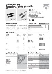
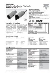
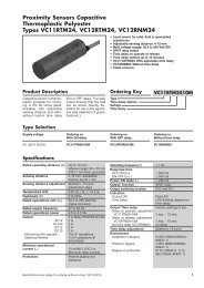
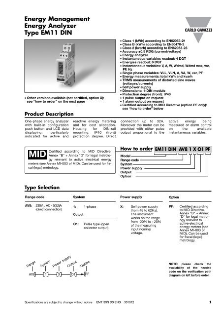
Energy Management<br />
Energy Analyzer<br />
Type <strong>EM11</strong> <strong>DIN</strong><br />
• Other versions available (not certified, option X):<br />
see “how to order” on the next page<br />
Product Description<br />
One-phase energy analyzer<br />
with built-in configuration<br />
push button and LCD data<br />
displaying; particularly<br />
indicated for active and<br />
reactive energy metering<br />
and for cost allocation.<br />
Housing for <strong>DIN</strong>-rail<br />
mounting, IP40 (front)<br />
protection degree. Direct<br />
Certified according to MID Directive,<br />
MID Annex "B" + Annex "D" for legal metrology<br />
relevant to active electrical energy<br />
meters (see Annex MI-003 of MID). Can be used for fiscal<br />
(legal) metrology.<br />
Type Selection<br />
Range code<br />
AV8: 230VLN AC - 5(32)A<br />
(direct connection)<br />
Range<br />
System<br />
Power <strong>supply</strong><br />
Output<br />
System<br />
1: 1-phase<br />
Output<br />
O1: Pulse type (open<br />
collector output)<br />
Option<br />
AV8 1 X O1 PF<br />
• Class 1 (kWh) according to EN62053-21<br />
• Class B (kWh) according to EN50470-3<br />
• Class 2 (kvarh) according to EN62053-23<br />
• Accuracy ±0.5 RDG (current/voltage)<br />
• Energy analyzer<br />
• Instantaneous variables readout: 4 DGT<br />
• Energies readout: 6 DGT<br />
• Instantaneous variables: V, A, W, Wdmd, Wdmd max, var,<br />
PF, Hz<br />
• Single phase variables: VLL, VLN, A, VA, W, var, PF<br />
• Energy measurements: total kWh and kvarh<br />
• TRMS measurements of distorted sine waves<br />
(voltages/currents)<br />
• Self power <strong>supply</strong><br />
• Dimensions: 1-<strong>DIN</strong> module<br />
• Protection degree (front): IP40<br />
• 1 pulse output on request<br />
• 1 alarm output on request<br />
• Certified according to MID Directive (option PF only):<br />
see “how to order” below<br />
connection up to 32A.<br />
Moreover the meter can be<br />
provided with either pulse<br />
output proportional to the<br />
How to order <strong>EM11</strong> <strong>DIN</strong> AV8 1 X O1 PF<br />
Model<br />
Range code<br />
System<br />
Power <strong>supply</strong><br />
Output<br />
Option<br />
Power <strong>supply</strong><br />
X: Self power <strong>supply</strong><br />
(from 48 to 62Hz).<br />
The instrument<br />
works on the range<br />
from -20% to +20%<br />
of the measuring<br />
input nominal<br />
voltage.<br />
active energy being<br />
measured or alarm control<br />
on the available<br />
instantaneous variables.<br />
Option<br />
PF: Certified according<br />
to MID Directive,<br />
Annex "B" + Annex<br />
"D" for legal metrology<br />
relevant to<br />
active electrical<br />
energy meters (see<br />
Annex MI-003 of<br />
MID). Can be used<br />
for fiscal (legal)<br />
metrology.<br />
NOTE: please check the<br />
availability of the needed<br />
code on the verification path<br />
diagram on left before order.<br />
Specifications are subject to change without notice <strong>EM11</strong><strong>DIN</strong> DS <strong>ENG</strong> 301012 1
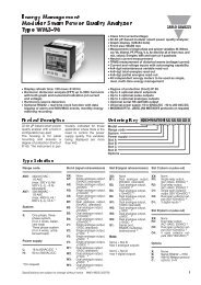
<strong>EM11</strong> <strong>DIN</strong><br />
STANDARD<br />
Not certified according to MID directive. Cannot be<br />
used for fiscal (legal) metrology.<br />
Type Selection<br />
Range code<br />
AV7: 120VLN AC - 5(32)A<br />
(direct connection)<br />
AV8: 230VLN AC - 5(32)A<br />
(direct connection)<br />
Range<br />
System<br />
Power <strong>supply</strong><br />
System<br />
1: 1-phase<br />
Output<br />
O1: Pulse type (open<br />
collector output)<br />
R1: Alarm type (relay<br />
output)<br />
Output<br />
Option<br />
AV7 1 X O1 X<br />
How to order <strong>EM11</strong> <strong>DIN</strong> AV8 1 X O1 X<br />
Model<br />
Range code<br />
System<br />
Power <strong>supply</strong><br />
Output<br />
Option<br />
Power <strong>supply</strong><br />
X: Self power <strong>supply</strong><br />
(from 48 to 62Hz).<br />
The instrument<br />
works on the range<br />
from -20% to +20%<br />
of the measuring<br />
input nominal<br />
voltage.<br />
Option<br />
X: none<br />
AV8 1 X O1<br />
R1<br />
X<br />
2 Specifications are subject to change without notice <strong>EM11</strong><strong>DIN</strong> DS <strong>ENG</strong> 301012<br />
Range<br />
System<br />
NOTE: please check the<br />
availability of the needed<br />
code on the verification path<br />
diagrams below before order.<br />
Power <strong>supply</strong><br />
Output<br />
Option
<strong>EM11</strong> <strong>DIN</strong><br />
Input specifications<br />
Rated inputs System: 1<br />
Current range (by shunt) AV7 and AV8: 5(32)A<br />
Voltage range AV7: 120 VLN AC<br />
AV8: 230 VLL AC<br />
Accuracy (Display)<br />
(@25°C ±5°C, R.H. ≤60%, 48 to 62Hz)<br />
AV7 model Ib: 5A, Imax: 32A;<br />
Un: 120VLN (-20% +20%)<br />
AV8 model Ib: 5A, Imax: 32A;<br />
Un: 230VLN (-20% +20%)<br />
Current From 0.04Ib to 0.2Ib, PF=1:<br />
±(0.5% RDG +3DGT)<br />
From 0.2Ib to Imax, PF=1:<br />
±(0.5% RDG +1DGT).<br />
Voltage In the Un range: ±(0.5%<br />
RDG +2DGT)<br />
Frequency ±0.1Hz (48 to 62Hz)<br />
Active power ±(1%RDG +2DGT)<br />
Reactive power ±(2%RDG +2DGT)<br />
Active energy Class 1 according to<br />
EN62053-21 and Class B<br />
according to EN50470-3.<br />
Reactive energy Class 2 according to<br />
EN62053-23.<br />
Reference values Ib: 5A, Imax: 32A,<br />
0.1 Ib: 0.5A<br />
Start up current: 20mA<br />
Energy additional errors<br />
Influence quantities According to EN62053-21,<br />
EN62053-23<br />
Temperature drift ≤200ppm/°C<br />
Sampling rate 4096 samples/s @ 50Hz<br />
4096 samples/s @ 60Hz<br />
Display refresh time 1 sec.<br />
Display 1 line (max: 6 DGT)<br />
Type LCD, h 7mm<br />
Output specifications<br />
Digital output<br />
Number of outputs 1, open collector<br />
X Option programmable, from 0.001<br />
to 1 kWh for each pulse.<br />
PF option Fixed, 0,001 kWh/pulse<br />
Signal VON 1.2 VDC/ max. 100 mA<br />
VOFF 30 VDC max.<br />
Pulse duration ≥100ms < 120msec (ON),<br />
≥120ms (OFF), according<br />
to EN62052-31<br />
Insulation By means of optocouplers,<br />
4000 VRMS output to<br />
measuring inputs<br />
Alarm output Not available in case of PF<br />
option.<br />
Number of outputs 1<br />
Type Relay, SPST type<br />
AC 1-5A @ 250VAC<br />
DC 12-5A @ 24VDC<br />
AC 15-1.5A @ 250VAC<br />
Instantaneous variables read-out 4 DGT (V and A)<br />
3 DGT (W, var, Wdmd,<br />
Wdmd max, Hz, PF)<br />
Min. Max. indication Max. 9 999;<br />
Min. 0 (0.0)<br />
Energies Total: 6 DGT<br />
LEDs Red LED (Energy consumption),<br />
1000 pulses/kWh<br />
(Max Frequency 16 Hz)<br />
according to EN62053-11<br />
Measurements See “Measuring variables<br />
and Min. Max. indications”<br />
Method TRMS measurements of<br />
distorted wave forms<br />
Coupling type Direct<br />
Crest factor Ib 5A ≤4 (45A max. peak)<br />
Current Overload<br />
Continuous 32A, @ 50Hz<br />
For 10ms 960A, @ 50Hz<br />
Voltage Overload<br />
Continuous 1.2 Un<br />
For 500ms 2 Un<br />
Input impedance<br />
120VL-N (AV7) >720KΩ<br />
230VL-N (AV8) >720KΩ<br />
5(32) A (AV7-AV8) < 0.5VA<br />
Frequency 48 to 62 Hz<br />
Key-pad 1 push-button for variable<br />
selection and programming<br />
of the instrument working<br />
parameters.<br />
Not available in case of<br />
“PF” option.<br />
DC 13-1.5A @ 24VDC<br />
Alarm modes Up alarm or down alarm<br />
Controlled variables kW, kWdmd, kvar, PF, A, V,<br />
Hz<br />
Set-point adjustment Programmable on all the<br />
measuring range (see<br />
“Measuring variables and<br />
Min. Max. indications”)<br />
Hysteresis programmable on all the<br />
measuring range (see<br />
“Measuring variables and<br />
Min. Max. indications”)<br />
On-time delay 0 to 9999s (166min)<br />
Off-time delay 0 to 9999s (166min)<br />
Min. response time 1s, set-point on-time delay:<br />
“0 s”<br />
Insulation 4000 VRMS output to<br />
measuring inputs<br />
Specifications are subject to change without notice <strong>EM11</strong><strong>DIN</strong> DS <strong>ENG</strong> 301012 3
<strong>EM11</strong> <strong>DIN</strong><br />
Software functions (Not available in case of PF option)<br />
Password Numeric code of max. 4<br />
digits; 2 protection levels<br />
of the programming data:<br />
1st level Password “0”, no protection;<br />
2nd level Password from 1 to 9999,<br />
all data are protected<br />
General specifications<br />
Operating temperature -25°C to +55°C (-13°F to<br />
131°F) (R.H. from 0 to 90%<br />
non-condensing @ 40°C)<br />
according to EN62053-21,<br />
EN50470-1 and EN62053-23<br />
Storage temperature -30°C to +70°C (-22°F to<br />
140°F) (R.H. < 90% noncondensing<br />
@ 40°C)<br />
according to EN62053-21,<br />
EN50470-1 and EN62053-23<br />
Installation category Cat. III (IEC60664,<br />
EN60664)<br />
Insulation (for 1 minute) 4000 VRMS between measuring<br />
inputs and digital<br />
output (O1 and R1).<br />
Dielectric strength 4000 VRMS for 1 minute<br />
CMRR Noise rejection 100 dB, 48 to 62 Hz<br />
EMC According to EN62052-11<br />
Electrostatic discharges 8kV air discharge;<br />
Immunity to irradiated<br />
electromagnetic fields Test with applied current:<br />
10V/m from 80 to 2000MHz;<br />
Test without any applied<br />
current: 30V/m from 80 to<br />
2000MHz;<br />
Burst On current and voltage<br />
measuring input circuits:<br />
4kV<br />
Immunity to conducted<br />
disturbances 10V/m from 150KHz to<br />
80MHz<br />
Power <strong>supply</strong> specifications<br />
Self supplied version 120VLN (AV7), 230 VLN<br />
(AV8) (-20% +20%)<br />
48-62Hz<br />
Displaying 1 variable per page (See<br />
«Measuring variables and<br />
Min. Max. indications»)<br />
Reset By means of the front<br />
key-pad:<br />
- W dmd max;<br />
- energies: kWh, kvarh<br />
Surge On current and voltage<br />
measuring input circuits:<br />
4kV;<br />
Radio frequency suppression According to CISPR 22<br />
Standard compliance<br />
Safety IEC60664, IEC61010-1<br />
EN60664, EN61010-1<br />
(EN62052-11) EN50470-1.<br />
Metrology EN62053-21, EN62053-23,<br />
EN50470-3.<br />
Pulse output <strong>DIN</strong>43864, IEC62053-31<br />
Approvals CE, cULus (X option)<br />
MID (PF option)<br />
Connections Screw-type<br />
Cable cross-section area Measuring inputs: min. 2.5<br />
mm 2 , max. 10 mm 2 ;<br />
Min./Max. screws tightening<br />
torque: 0.5 Nm / 1.1 Nm<br />
Other terminals: 1.5 mm 2 .<br />
Screws tightening torque:<br />
0.5 Nm<br />
<strong>DIN</strong> Housing<br />
Dimensions (WxHxD) 17.5 (+0.5 -0) x 90 x 67.5 mm<br />
Material Nylon PA66,<br />
self-extinguishing: UL 94 V-0<br />
Mounting <strong>DIN</strong>-rail<br />
Protection degree<br />
Front IP40<br />
Screw terminals IP20<br />
Weight Approx. 100 g (packing<br />
included)<br />
Power consumption ≤ 3VA<br />
4 Specifications are subject to change without notice <strong>EM11</strong><strong>DIN</strong> DS <strong>ENG</strong> 301012
<strong>EM11</strong> <strong>DIN</strong><br />
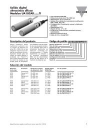
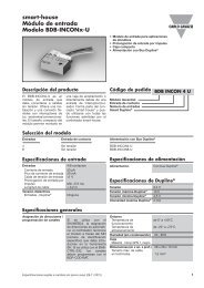
Accuracy (according to EN50470-3 and EN62053-23)<br />
kWh, accuracy (RDG) depending on the current<br />
+1.5%<br />
+1%<br />
0%<br />
-1%<br />
-1.5%<br />
PF=1<br />
PF=L0.5<br />
or C0.8<br />
Percentage error limits for class index B<br />
0.25A<br />
(0.5Iref)<br />
0.5A<br />
(0,1Iref)<br />
0.5A<br />
(0,1Iref)<br />
5A (Iref)<br />
5A (Iref)<br />
Class 1 accuracy limits (Active energy)<br />
5(32)A Start-up current: 20mA<br />
32A (Imax)<br />
32A (Imax)<br />
kvarh, accuracy (RDG) depending on the current<br />
+2.5%<br />
+2%<br />
Specifications are subject to change without notice <strong>EM11</strong><strong>DIN</strong> DS <strong>ENG</strong> 301012 5<br />
0%<br />
-2%<br />
-2.5%<br />
sinϕ=1<br />
sinϕ=0.5<br />
Error<br />
0.25A<br />
(0.05Ib)<br />
0.5A<br />
(0.1Ib)<br />
MID “Annex MI-003” compliance (PF option only)<br />
Accuracy 0.9 Un ≤ U ≤ 1.1 Un;<br />
0.98 fn ≤ f ≤ 1.02 fn;<br />
fn: 50 or 60Hz;<br />
cosϕ: 0.5 inductive to 0.8<br />
capacitive.<br />
Class B<br />
I st: 0.02A; I min: 0.25A;<br />
I tr: 0.5A; I ref: 5A;<br />
I max: 32A.<br />
Operating temperature -25°C to +55°C (-13°F to<br />
131°F) (R.H. from 0 to 90%<br />
non-condensing @ 40°C)<br />
Used calculation formulas<br />
Phase variables<br />
Instantaneous effective voltage<br />
Instantaneous active power<br />
Instantaneous power factor<br />
Instantaneous effective current<br />
Instantaneous apparent power<br />
Instantaneous reactive power<br />
Where: n= sample number<br />
Energy metering<br />
Where:<br />
P= active power;<br />
Q= reactive power;<br />
t1, t2 =starting and ending time points<br />
of consumption recording;<br />
nj= time unit;<br />
∆t= time interval between two<br />
successive power consumptions;<br />
n1, n2 = starting and ending discrete<br />
time points of consumption recording<br />
0.5A<br />
(0.1Ib)<br />
1A<br />
(0.25Ib)<br />
5A (Ib)<br />
5A (Ib)<br />
Class 2 accuracy limits (Reactive energy)<br />
5(32)A Start-up current: 20mA<br />
32A (Imax)<br />
32A (Imax)<br />
EMC compliance E2<br />
Mechanical compliance M2<br />
Protection degree in order to achieve the<br />
protection against dust and<br />
water required by the<br />
norms harmonized to MID,<br />
the meter must be used<br />
only installed in IP51 (or<br />
better) cabinets.
<strong>EM11</strong> <strong>DIN</strong><br />
Measuring variables and Min. Max. indications<br />
Page number Variable Min. Max. Indication Notes<br />
Insulation between inputs and outputs<br />
Measuring inputs Relay output<br />
Open collector<br />
output<br />
AC self-power <strong>supply</strong><br />
Measuring inputs - 4kV 4kV 0kV<br />
Relay output 4kV - 4kV 4kV<br />
Open collector<br />
output<br />
1 kWh<br />
from 0.01 to 999999,<br />
autoranging.<br />
Total (only consumed energy)<br />
2 kvarh from 0.0 to 99999.9 Total (only consumed energy)<br />
3 kW from 0.00 to 9.99<br />
4 kW dmd from 0.00 to 9.99<br />
Integration time progammable from 1 to<br />
30 minutes<br />
5 kW dmd max from 0.00 to 9.99 Max value with data storage (in EEprom)<br />
6 V from 0.0 to 999.9<br />
7 A from 0.0 to 32.00<br />
8 Hz from 48.0 to 62.0<br />
9 PF (cosϕ) from L/C. 00 to L/C. 99<br />
10 kvar from 0.00 to 9.99<br />
Note: In case of X option all the variables above can be scrolled using the front push button, in case of PF option the push<br />
button is not available and the variables are automatically scrolled.<br />
4kV 4kV - 4kV<br />
AC self-power <strong>supply</strong> 0kV 4kV 4kV -<br />
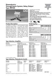
Wiring diagrams and relay output (R1)<br />
NOTE: The 3 and 4 terminals, in the instrument, are wired together<br />
1-phase connection Fig. 1 1 relay output Fig. 2<br />
6 Specifications are subject to change without notice <strong>EM11</strong><strong>DIN</strong> DS <strong>ENG</strong> 301012
<strong>EM11</strong> <strong>DIN</strong><br />
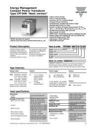
Wiring diagrams and open collector output (O1)<br />
1-phase connection Fig. 1<br />
NOTE: The 3 and 4 terminals, in the instrument, are<br />
wired together<br />
Frontal panel description<br />
3<br />
Dimensions and panel cut-out<br />
45mm<br />
2<br />
44mm<br />
67.5mm<br />
1<br />
1 open collector output Fig. 2<br />
VDC VDC<br />
VDC Reference<br />
GND Reference<br />
The load resistances (RC) must be designed so that the close<br />
contact current is lower than 100mA; the VDC voltage must be<br />
lower than or equal to 30VDC.<br />
1. Push button<br />
To program the configuration parameters and the display<br />
of the variables.<br />
Not available in case of PF option.<br />
2. LED<br />
Red LED to show the consumed energy.<br />
3. Display<br />
LCD-type with alphanumeric indication to:<br />
- display configuration parameters;<br />
- display all the measured variables.<br />
17.5 +0.5/-0mm<br />
Specifications are subject to change without notice <strong>EM11</strong><strong>DIN</strong> DS <strong>ENG</strong> 301012 7<br />
90mm<br />
45.5mm<br />
18mm