DMC-21x3 Amplifier and Accessory Manual - Galil
DMC-21x3 Amplifier and Accessory Manual - Galil
DMC-21x3 Amplifier and Accessory Manual - Galil

Create successful ePaper yourself
Turn your PDF publications into a flip-book with our unique Google optimized e-Paper software.
USER MANUAL / COMMAND REFERENCE<br />
<strong>DMC</strong>-<strong>21x3</strong><br />
<strong>Amplifier</strong>s<br />
& Accessories<br />
<strong>Manual</strong> Rev. 1.0o<br />
<strong>Galil</strong> Motion Control, Inc.<br />
270 Technology Way<br />
Rocklin, California 95765<br />
Phone: (916) 626-0101<br />
Fax: (916) 626-0102<br />
E-mail Address: support@galilmc.com<br />
URL: www.galilmc.com<br />
Rev 01/11
Using This <strong>Manual</strong><br />
This user manual provides information for proper operation of the daughter boards that connect to the<br />
<strong>DMC</strong>-<strong>21x3</strong> controllers. It also includes a small listing of comm<strong>and</strong>s that pertain to the daughter<br />
boards. This is a subset of the comm<strong>and</strong>s listed in the comm<strong>and</strong> reference you received with your<br />
motion controller.<br />
Please note that many examples are written for the <strong>DMC</strong>-2143 four-axes controller or the <strong>DMC</strong>-2183<br />
eight axes controller. Users of the <strong>DMC</strong>-2133 3-axis controller, <strong>DMC</strong>-2123 2-axes controller or<br />
<strong>DMC</strong>-2113 1-axis controller should note that the <strong>DMC</strong>-2133 uses the axes denoted as XYZ, the <strong>DMC</strong>-<br />
2123 uses the axes denoted as XY, <strong>and</strong> the <strong>DMC</strong>-2113 uses the X-axis only.<br />
Examples for the <strong>DMC</strong>-2183 denote the axes as A,B,C,D,E,F,G,H. Users of the <strong>DMC</strong>-2153 5-axes<br />
controller denotes the axes as A,B,C,D,E. <strong>DMC</strong>-2163 6-axes controller denotes the axes as<br />
A,B,C,D,E,F. <strong>DMC</strong>-2173, 7-axes controller denotes the axes as A,B,C,D,E,F,G. In other words, the<br />
axes names A,B,C,D may be used interchangeably with X, Y, Z, W.<br />
WARNING: Machinery in motion can be dangerous! It is the responsibility of the user to design<br />
effective error h<strong>and</strong>ling <strong>and</strong> safety protection as part of the machine. <strong>Galil</strong> shall not be liable or<br />
responsible for any incidental or consequential damages.
Contents<br />
CONTENTS ................................................................................................................................................................ 1<br />
CHAPTER 1 OVERVIEW ........................................................................................................................................ 5<br />
INTRODUCTION......................................................................................................................................................... 5<br />
DC TO DC OPTION ................................................................................................................................................... 5<br />
PINOUT ..................................................................................................................................................................... 5<br />
DC TO DC PASS THROUGH....................................................................................................................................... 6<br />
MODULE TYPES........................................................................................................................................................ 6<br />
Servo Drives........................................................................................................................................................ 6<br />
Stepper Drives..................................................................................................................................................... 6<br />
Non <strong>Amplifier</strong> Modules ....................................................................................................................................... 6<br />
Cables ................................................................................................................................................................. 7<br />
CHAPTER 2 SR-19900 ............................................................................................................................................ 9<br />
INTRODUCTION......................................................................................................................................................... 9<br />
LAYOUT.................................................................................................................................................................. 11<br />
PINOUT ................................................................................................................................................................... 11<br />
CONFIGURATION..................................................................................................................................................... 11<br />
CHAPTER 3 ICM-20100 ....................................................................................................................................... 13<br />
INTRODUCTION....................................................................................................................................................... 13<br />
LAYOUT.................................................................................................................................................................. 14<br />
PINOUT ................................................................................................................................................................... 15<br />
AMPLIFIER ENABLE ................................................................................................................................................ 17<br />
CHAPTER 4 ICM-20105 ....................................................................................................................................... 19<br />
INTRODUCTION....................................................................................................................................................... 19<br />
ELECTRICAL SPECIFICATIONS................................................................................................................................. 20<br />
LAYOUT.................................................................................................................................................................. 20<br />
PINOUT ................................................................................................................................................................... 21<br />
CONFIGURATIONS FOR ICM-20105 ........................................................................................................................ 23<br />
<strong>Amplifier</strong> Enable Circuit................................................................................................................................... 23<br />
Opto Isolation Settings...................................................................................................................................... 25<br />
CHAPTER 5 SDM-20240/20242............................................................................................................................ 27<br />
INTRODUCTION....................................................................................................................................................... 27<br />
ELECTRICAL SPECIFICATIONS................................................................................................................................. 28<br />
LAYOUT.................................................................................................................................................................. 28<br />
PINOUT ................................................................................................................................................................... 29<br />
Mating Connectors............................................................................................................................................ 31<br />
<strong>DMC</strong>-<strong>21x3</strong> Accessories Contents• 1
CONFIGURATIONS FOR SDM-20240 & SDM-20242............................................................................................... 31<br />
Motor Current Setting....................................................................................................................................... 31<br />
Low Current Setting (JP1) ................................................................................................................................ 32<br />
ADDITIONAL SETTINGS FOR SDM-20242 ............................................................................................................... 33<br />
Protection Circuitry <strong>and</strong> Error LED................................................................................................................. 33<br />
ELO (Emergency Lock Out).............................................................................................................................. 33<br />
Fault Output from SDM-20242......................................................................................................................... 33<br />
CHAPTER 6 AMP-20341 ...................................................................................................................................... 35<br />
INTRODUCTION....................................................................................................................................................... 35<br />
ELECTRICAL SPECIFICATIONS................................................................................................................................. 36<br />
LAYOUT.................................................................................................................................................................. 36<br />
PINOUT ................................................................................................................................................................... 37<br />
Mating Connectors............................................................................................................................................ 38<br />
CHAPTER 7 AMP-20440/20420 ........................................................................................................................... 39<br />
INTRODUCTION....................................................................................................................................................... 39<br />
ELECTRICAL SPECIFICATIONS................................................................................................................................. 40<br />
LAYOUT.................................................................................................................................................................. 40<br />
PINOUT ................................................................................................................................................................... 41<br />
OVER-VOLTAGE PROTECTION ................................................................................................................................ 43<br />
OVER-CURRENT PROTECTION ................................................................................................................................ 43<br />
ABORT INPUT OPTIONS........................................................................................................................................... 44<br />
CHAPTER 8 ICM-20500 ....................................................................................................................................... 45<br />
INTRODUCTION....................................................................................................................................................... 45<br />
ELECTRICAL SPECIFICATIONS................................................................................................................................. 46<br />
LAYOUT.................................................................................................................................................................. 46<br />
PINOUT ................................................................................................................................................................... 47<br />
CONFIGURATION..................................................................................................................................................... 48<br />
CHAPTER 9 AMP-20540/20520 ............................................................................................................................. 49<br />
INTRODUCTION....................................................................................................................................................... 49<br />
ELECTRICAL SPECIFICATIONS................................................................................................................................. 50<br />
LAYOUT.................................................................................................................................................................. 50<br />
PINOUT ................................................................................................................................................................... 51<br />
Mating Connectors............................................................................................................................................ 53<br />
OPERATION............................................................................................................................................................. 54<br />
Brushless Motor Setup ...................................................................................................................................... 54<br />
Brushless <strong>Amplifier</strong> Software Setup .................................................................................................................. 54<br />
Brush <strong>Amplifier</strong> Operation................................................................................................................................ 55<br />
Using External <strong>Amplifier</strong>s................................................................................................................................. 55<br />
Error Monitoring <strong>and</strong> Protection...................................................................................................................... 56<br />
Hall Error Protection........................................................................................................................................ 56<br />
Under-Voltage Protection................................................................................................................................. 57<br />
Over-Voltage Protection ................................................................................................................................... 57<br />
Over-Current Protection................................................................................................................................... 57<br />
Over-Temperature Protection........................................................................................................................... 57<br />
ABORT INPUT OPTIONS........................................................................................................................................... 58<br />
CHAPTER 10 AMP-20542 (OBSOLETE) ............................................................................................................. 59<br />
INTRODUCTION....................................................................................................................................................... 59<br />
ELECTRICAL SPECIFICATIONS................................................................................................................................. 60<br />
LAYOUT.................................................................................................................................................................. 60<br />
PINOUT ................................................................................................................................................................... 61<br />
Mating Connectors............................................................................................................................................ 63<br />
2 • Contents <strong>DMC</strong>-<strong>21x3</strong> Accessories
OPERATION............................................................................................................................................................. 64<br />
Brushless Motor Setup ...................................................................................................................................... 64<br />
Brushless <strong>Amplifier</strong> Software Setup .................................................................................................................. 64<br />
Brush <strong>Amplifier</strong> Operation................................................................................................................................ 65<br />
Using External <strong>Amplifier</strong>s................................................................................................................................. 65<br />
Error Monitoring <strong>and</strong> Protection...................................................................................................................... 65<br />
Hall Error Protection........................................................................................................................................ 66<br />
Under-Voltage Protection................................................................................................................................. 66<br />
Over-Voltage Protection ................................................................................................................................... 66<br />
Over-Current Protection................................................................................................................................... 66<br />
ABORT INPUT OPTIONS........................................................................................................................................... 66<br />
CHAPTER 11 SDM-20640/20620............................................................................................................................ 67<br />
INTRODUCTION....................................................................................................................................................... 67<br />
ELECTRICAL SPECIFICATIONS................................................................................................................................. 68<br />
LAYOUT.................................................................................................................................................................. 68<br />
PINOUT ................................................................................................................................................................... 68<br />
Mating Connectors............................................................................................................................................ 70<br />
CONFIGURATIONS FOR SDM-206X0....................................................................................................................... 71<br />
Current Level Setup (AG Comm<strong>and</strong>) ................................................................................................................ 71<br />
Low Current Setting (LC Comm<strong>and</strong>) ................................................................................................................ 71<br />
ABORT INPUT OPTIONS........................................................................................................................................... 71<br />
CHAPTER 12 PCM-20900 .................................................................................................................................... 73<br />
INTRODUCTION....................................................................................................................................................... 73<br />
CHAPTER 13 DB-28040........................................................................................................................................ 75<br />
INTRODUCTION....................................................................................................................................................... 75<br />
LAYOUT.................................................................................................................................................................. 76<br />
PINOUT ................................................................................................................................................................... 77<br />
Electrical Specifications3.3V I/O (St<strong>and</strong>ard).................................................................................................... 78<br />
Sink/Source 4mA per output5V I/O (-5V Option)....................................................................................... 78<br />
Analog Inputs.................................................................................................................................................... 78<br />
INTERFACING TO THE DIGITAL I/O ......................................................................................................................... 78<br />
SSI ......................................................................................................................................................................... 79<br />
DB-28040 AND AMP-205X0.................................................................................................................................. 79<br />
DB-28040 AND AMP-205X2 OR SDM-20640........................................................................................................ 79<br />
CHAPTER 14 DB-28104.......................................................................................................................................... 81<br />
INTRODUCTION....................................................................................................................................................... 81<br />
LAYOUT.................................................................................................................................................................. 83<br />
THEORY OF OPERATION.......................................................................................................................................... 83<br />
SETTING UP THE ENCODER ..................................................................................................................................... 85<br />
TUNING THE SYSTEM.............................................................................................................................................. 87<br />
EXAMPLE SIN/COS ENCODERS ................................................................................................................................ 89<br />
CHAPTER 15 CABLES FOR AMP-20XXX ....................................................................................................... 91<br />
APPENDIX A ABORT INPUT OPTIONS ........................................................................................................... 97<br />
ELO SCENARIOS..................................................................................................................................................... 97<br />
<strong>DMC</strong>-2143 with AMP-20540 ............................................................................................................................ 97<br />
<strong>DMC</strong>-2143 with SDM-20640 ............................................................................................................................ 98<br />
<strong>DMC</strong>-2183 with two AMP-20440s.................................................................................................................... 98<br />
APPENDIX B MATING D-SHELLS .................................................................................................................. 101<br />
APPENDIX C COMMAND REFERENCE ........................................................................................................ 103<br />
<strong>DMC</strong>-<strong>21x3</strong> Accessories Contents• 3
AE.................................................................................................................................................................... 104<br />
AG ................................................................................................................................................................... 105<br />
AU ................................................................................................................................................................... 106<br />
AW................................................................................................................................................................... 107<br />
BR.................................................................................................................................................................... 108<br />
BS.................................................................................................................................................................... 109<br />
CN ................................................................................................................................................................... 110<br />
CO................................................................................................................................................................... 111<br />
LC.................................................................................................................................................................... 112<br />
QH................................................................................................................................................................... 113<br />
TA.................................................................................................................................................................... 114<br />
TK.................................................................................................................................................................... 115<br />
TL (Binary 8a)................................................................................................................................................ 116<br />
4 • Contents <strong>DMC</strong>-<strong>21x3</strong> Accessories
Chapter 1 Overview<br />
________________________________________________________________________<br />
Introduction<br />
<strong>Galil</strong>’s <strong>DMC</strong>-<strong>21x3</strong> series motion controllers connect with daughterboard modules that mount directly<br />
on the motion controller. This eliminates the need for a separate cable between the motion controller<br />
<strong>and</strong> the amplifier or breakout module. This approach saves the cost of the cable <strong>and</strong> significantly<br />
reduces the real estate required for the controls within a system.<br />
The <strong>DMC</strong>-<strong>21x3</strong> uses a rugged 96 pin DIN board-to-board connector to interface the daughter boards<br />
with the motion controller. The same controller can be ordered with different modules for different<br />
system requirements. This controller series supports modules ranging from passive breakout modules<br />
to 500W-per-channel brush <strong>and</strong> brushless servo drives to stepper <strong>and</strong> microstepper drives. Each<br />
module breaks out the I/O provided by the controller <strong>and</strong> some of the boards also provide additional<br />
I/O functions such as analog inputs or optoisolation. If you do not find the exact module you are<br />
looking for, please contact <strong>Galil</strong> at 800-377-6329. We will work closely with you to create a module<br />
that will fit your needs.<br />
DC to DC Option<br />
Pinout<br />
The <strong>DMC</strong>-<strong>21x3</strong> series controllers can be ordered with an optional DC-to-DC converter so that a single DC<br />
power supply can be used to power the controller (as opposed to the st<strong>and</strong>ard 5 V <strong>and</strong> +/-12 V input). This<br />
can be ordered as either the –DC24 (18-36 VDC range) or –DC48 (36-72 VDC range). With the DC<br />
option, a 4-pin molex power connector is provided for DC supply to controller at J99.<br />
J99 4-Pin Molex<br />
1 Earth (optional)<br />
2 No connection<br />
3 Vin (18-36 or 36-72 VDC)<br />
4 GND<br />
Mating connector = AMP #770 849-4<br />
Pins = AMP #770 476-1<br />
<strong>DMC</strong>-<strong>21x3</strong> Accessories Chapter 1 Overview• 5
DC to DC Pass Through<br />
When using the DC-to-DC converter in conjunction with the <strong>Galil</strong> amplifier daughter boards described in<br />
this manual, there is an option to have the DC power supply input shared among both boards, which<br />
alleviates the need to supply power to two connectors. Power is passed through from the amp to the<br />
controller via the “Pass Through” header located at J98 (1-4 axes) or JP14 (5-8 axes) on the controller.<br />
When using the pass through on a 1-4 axis <strong>DMC</strong>-<strong>21x3</strong> controller, DC power must be applied only to the<br />
amplifier’s power connector.<br />
When using the pass through on a 5-8 axis <strong>DMC</strong>-<strong>21x3</strong> controller, DC power must be applied to both<br />
amplifier’s power connectors. Power is passed through to the controller only from the second (axes E-H)<br />
amplifier<br />
The proper DC-to-DC converter must be chosen so that the DC voltage range is compatible with the<br />
amplifier <strong>and</strong> motor voltage requirements. The J98/JP14 header comes st<strong>and</strong>ard, hence the purchaser must<br />
specify if they would not like this header present with –NOJ98.<br />
Module Types<br />
Servo Drives<br />
Part Number Description<br />
AMP-20340 4 Axis Brush Type 20 Watt Linear Servo Drives. OBSELETE<br />
AMP-20341 4 Axis Brush Type 20 Watt Linear Servo Drives (bipolar supply)<br />
AMP-20420 2 Axis Brush Type 200 Watt/Axis PWM Servo Drives<br />
AMP-20440 4 Axis Brush Type 200 Watt/Axis PWM Servo Drives<br />
AMP-20520 2 Axis Brushless/Brush 500 Watt/Axis PWM Servo Drives<br />
AMP-20540 4 Axis Brushless/Brush 500 Watt/Axis PWM Servo Drives<br />
Stepper Drives<br />
Part Number Description<br />
SDM-20240 4 Axis 2 Phase Full/Half Step Stepper Motor Drive<br />
SDM-20620 2 Axis 2 Phase Micro Stepper Motor Drive<br />
SDM-20640 4 Axis 2 Phase Micro Stepper Motor Drive<br />
Non <strong>Amplifier</strong> Modules<br />
Part Number Description<br />
ICM-20100 4 Axis Breakout to D Shell Connectors<br />
ICM-20105 4 Axis Breakout to D Shell Connectors with opto-isolated I/O<br />
DB-28040 Additional Configurable I/O <strong>and</strong> 8 Dedicated Analog Inputs<br />
DB-28104 Accepts Sin/Cos Encoder Feedback<br />
PCM-20900 Breadboard Module to Aid Design of Customer Daughter Boards<br />
SR-19900 Shunt Regulator<br />
6 • Chapter 1 Overview <strong>DMC</strong>-<strong>21x3</strong> Accessories
Cables<br />
Part Number Description<br />
CABLE-15-1m<br />
CABLE-44-1m<br />
15-pin high density D-sub cable with 1 m flying leads (AMP-204x0 <strong>and</strong><br />
AMP-205x0)<br />
44-pin high density D-sub cable with 1 m flying leads (AMP-204x0 <strong>and</strong><br />
AMP-205x0)<br />
<strong>DMC</strong>-<strong>21x3</strong> Accessories Chapter 1 Overview• 7
THIS PAGE LEFT BLANK INTENTIONALLY<br />
8 • Chapter 1 Overview <strong>DMC</strong>-<strong>21x3</strong> Accessories
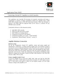
Chapter 2 SR-19900<br />
____________________________________________________________________________<br />
Introduction<br />
For applications requiring a shunt regulator, <strong>Galil</strong> offers a small mountable model that can be configured for varying<br />
voltage levels. Two fixed voltage threshold settings are available with jumpers, which can be set at either 33 or 66<br />
volts. Additionally, a user defined voltage threshold can be set by changing a simple resistor. This shunt regulator<br />
operates with hysteresis, where the regulator switches on at the set voltage threshold <strong>and</strong> switches off at 2 volts<br />
below.<br />
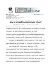
The shunt regulator should be placed in parallel with the power supply as in the figure below, <strong>and</strong> it should be<br />
mounted to a metal surface using thermal grease to aid in heat transfer. Connections are made to the unit at VS<br />
(voltage supply) <strong>and</strong> PG (power ground) using either the 4-pin Molex connector or the 8-pin Mate ‘N Lock<br />
connector (AMP# 770579-1).<br />
For a summary of shunt regulator operation, as well as details to help determine if one is required in your system,<br />
please refer to application note #5448 at: (http://www.galilmc.com/support/appnotes/miscellaneous/note5448.pdf).<br />
<strong>DMC</strong>-<strong>21x3</strong> Accessories Chapter 2 SR-19900• 9
SR-19900<br />
Shunt<br />
Regulator<br />
Controller<br />
GND<br />
MOCMDx<br />
AEN<br />
DCPower<br />
Supply<br />
+ -<br />
+ -<br />
PWM<br />
<strong>Amplifier</strong><br />
M+<br />
M-<br />
10 • Chapter 2 SR-19900 <strong>DMC</strong>-<strong>21x3</strong> Accessories<br />
Motor<br />
Encoder<br />
Figure 1 Shunt Regulator Placement in a Typical Servo System<br />
System Load<br />
(Inertia)
Layout<br />
Pinout<br />
Configuration<br />
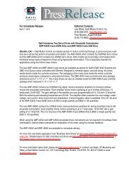
Figure 2 SR-19900 Layout<br />
J2 4-pin Molex J1 8-pin Mate ‘N Lock<br />
Power Ground 1 PG 1 Earth 5 PG<br />
Voltage Supply 2 VS 2 VS 6 PG<br />
Power Ground 3 PG 3 VS 7 PG<br />
Voltage Supply 4 VS 4 VS 8 PG<br />
SR-19900 Configuration<br />
USR - User Settable Voltage<br />
R8 = 1930 * Vs -42.2K<br />
Voltage Threshold<br />
Voltage<br />
Setting (Vs) JP1<br />
(Vs) R8 value (ohms)<br />
33 volts 33V 24 4.12 k<br />
66 volts 66V 48 50.44 k<br />
User selectable USR 72 96.76 k<br />
<strong>DMC</strong>-<strong>21x3</strong> Accessories Chapter 2 SR-19900• 11
THIS PAGE LEFT BLANK INTENTIONALLY<br />
12 • Chapter 2 SR-19900 <strong>DMC</strong>-<strong>21x3</strong> Accessories
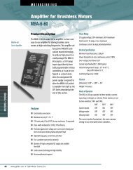
Chapter 3 ICM-20100<br />
__________________________________________________________________<br />
Introduction<br />
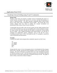
The ICM-20100 interconnect module provides D-Sub connections between the <strong>DMC</strong>-<strong>21x3</strong> series<br />
controllers <strong>and</strong> other system elements, such as amplifiers, encoders, <strong>and</strong> external switches. The<br />
ICM-20100 provides access to the signals for up to 4 axes (two required for 5 or more axes).<br />
Figure 3 ICM-20100<br />
<strong>DMC</strong>-<strong>21x3</strong> Accessories Chapter 3 ICM-20100• 13
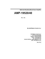
Layout<br />
Drawing Not to Scale. For Reference Only. Dimensions are inches<br />
Figure 4 ICM-20100 Layout<br />
Board Dimensions are 3.7” x 4.25”. See Application Note #1231 for Hole Locations.<br />
14 • Chapter 3 ICM-20100 <strong>DMC</strong>-<strong>21x3</strong> Accessories
Pinout<br />
J6 X-Axis 15-pin Male D-sub J5 J5 Y-Axis 15-pin Male D-sub<br />
1 Forward limit X 1 Forward limit Y<br />
2 Home X 2 Home Y<br />
3 5V 3 5V<br />
4 A- X 4 A- Y<br />
5 B- X 5 B- Y<br />
6 I- X 6 I- Y<br />
7 Amp enable X 7 Amp enable Y<br />
8 Sign/dir X 8 Sign/dir Y<br />
9 Reverse limit X 9 Reverse limit Y<br />
10 Ground 10 Ground<br />
11 A+ X 11 A+ Y<br />
12 B+ X 12 B+ Y<br />
13 I+ X 13 I+ Y<br />
14 Motor comm<strong>and</strong> X 14 Motor comm<strong>and</strong> Y<br />
15 PWM/step X 15 PWM/step Y<br />
J4 J4 Z-Axis 15-pin Male D-sub J3 W-Axis 15-pin Male D-sub<br />
1 Forward Limit Z 1 Forward Limit W<br />
2 Home Z 2 Home W<br />
3 5V 3 5V<br />
4 A- Z 4 A- W<br />
5 B- Z 5 B- W<br />
6 I- Z 6 I- W<br />
7 Amp enable Z 7 Amp enable W<br />
8 Sign/dir Z 8 Sign/dir W<br />
9 Reverse limit Z 9 Reverse limit W<br />
10 Ground 10 Ground<br />
11 A+ Z 11 A+ W<br />
12 B+ Z 12 B+ W<br />
13 I+ Z 13 I+ W<br />
14 Motor comm<strong>and</strong> Z 14 Motor comm<strong>and</strong> W<br />
15 PWM/step Z 15 PWM/step W<br />
<strong>DMC</strong>-<strong>21x3</strong> Accessories Chapter 3 ICM-20100• 15
J10 Aux Encoders 25-pin Female D-Sub J11 I/O 25-pin Male D-Sub<br />
1 Reset * 1 Ground<br />
2 AB- W 2 Latch X/Input 1<br />
3 AA- W 3 Latch Z/Input 3<br />
4 AB- Z 4 Input 5<br />
5 AA- Z 5 Input 7<br />
6 AB- Y 6 Abort *<br />
7 AA- Y 7 Output 1<br />
8 AB- X 8 Output 3<br />
9 AA- X 9 Output 5<br />
10 5V 10 Output 7<br />
11 5V 11 Ground<br />
12 +12V 12 NC<br />
13 NC 13 NC<br />
14 Error Output * 14 5V<br />
15 AB+ W 15 Latch Y/Input 2<br />
16 AA+ W 16 Latch W/Input 4<br />
17 AB+ Z 17 Input 6<br />
18 AA+ Z 18 Input 8<br />
19 AB+ Y 19 Encoder-compare output<br />
20 AA+ Y 20 Output 2<br />
21 AB+ X 21 Output 4<br />
22 AA+ X 22 Output 6<br />
23 Ground 23 Output 8<br />
24 Ground 24 5V<br />
25 -12V 25 NC<br />
* Active Low Signal<br />
16 • Chapter 3 ICM-20100 <strong>DMC</strong>-<strong>21x3</strong> Accessories
<strong>Amplifier</strong> Enable<br />
The st<strong>and</strong>ard configuration of the AMPEN signal is TTL active high. In other words, the AMPEN<br />
signal will be high when the controller expects the amplifier to be enabled. The polarity <strong>and</strong> the<br />
amplitude can be changed. To change the polarity from active high (5 volts= enable, zero volts =<br />
disable) to active low (zero volts = enable, 5 volts= disable), replace the 7407 IC with a 7406<br />
(U2). Note that many amplifiers designate the enable input as ‘inhibit’.<br />
To change the voltage level of the AMPEN signal, note the state of the resistor pack on the ICM-<br />
20100. When pin 1 of the resistor matches pin 1 of the RP1, the output voltage is 0-5 V. To<br />
change to 12 volts, pull the resistor pack <strong>and</strong> rotate it so that pin 1 is on the 12 volt side. Pin 1 of<br />
the resistor will be marked with a designator, pin 1 of location RP1 can be determined by the<br />
square through hole on the circuit board denoting pin 1. If you remove the resistor pack, the<br />
output signal is open collector, allowing the user to connect an external supply with voltages up to<br />
24V. Note that any external pull-up resistor should limit the current draw to 10 mA<br />
Figure<br />
Figure 5 ICM-20100 <strong>Amplifier</strong> Enable Circuit<br />
<strong>DMC</strong>-<strong>21x3</strong> Accessories Chapter 3 ICM-20100• 17<br />
RP1
THIS PAGE LEFT BLANK INTENTIONALLY<br />
18 • Chapter 3 ICM-20100 <strong>DMC</strong>-<strong>21x3</strong> Accessories
Chapter 4 ICM-20105<br />
__________________________________________________________________<br />
Introduction<br />
The ICM-20105 opto-isolated I/O module are used with <strong>DMC</strong>-<strong>21x3</strong> controllers. It has four 15-pin<br />
Male D-Sub connectors for individual axis signals. There is one 37-pin D-Sub for the 8 digital<br />
inputs, 8 high side drive 500 mA digital outputs, home switches, limit switches, <strong>and</strong> one 25-pin D-<br />
Sub for 4 axes of auxiliary encoders.<br />
Figure 6 ICM-20105 shown mounted to a <strong>DMC</strong>-2143<br />
<strong>DMC</strong>-<strong>21x3</strong> Accessories Chapter 4 ICM-20105• 19
Electrical Specifications<br />
Layout<br />
Input Common Max Voltage 28 VDC<br />
Output Common Max Voltage 30 VDC<br />
Max Drive Current per Output 0.5 A (not to exceed 3A for all 8 outputs)<br />
Minimum Current to turn on Inputs 1 mA<br />
Max Enable Current @24V source 25 mA<br />
Drawing Not to Scale. For Reference Only. Dimensions are inches.<br />
Figure 7 ICM-20105 Dimensions <strong>and</strong> Jumper Locations<br />
Overall Dimensions: 4.25” x 3.70”<br />
20 • Chapter 4 ICM-20105 <strong>DMC</strong>-<strong>21x3</strong> Accessories
Pinout<br />
JX X-axis 15-Pin Male D-sub JY Y-axis 15-Pin Male D-sub<br />
1 Amp enable common-1 (AECOM1) 1 Amp enable common-1 (AECOM1)<br />
2 Amp enable X 2 Amp enable Y<br />
3 5V 3 5V<br />
4 A- X 4 A- Y<br />
5 B- X 5 B- Y<br />
6 I- X 6 I- Y<br />
7 NC 7 NC<br />
8 Sign/dir X 8 Sign/dir Y<br />
9 Amp enable common-2 (AECOM2) 9 Amp enable common-2 (AECOM2)<br />
10 Ground 10 Ground<br />
11 A+ X 11 A+ Y<br />
12 B+ X 12 B+ Y<br />
13 I+ X 13 I+ Y<br />
14 Motor comm<strong>and</strong> X 14 Motor Comm<strong>and</strong> Y<br />
15 PWM/step X 15 PWM/step Y<br />
JZ Z-axis 15-Pin Male D-sub JW W-axis 15-Pin Male D-sub<br />
1 Amp enable common-1 (AECOM1) 1 Amp enable common-1 (AECOM1)<br />
2 Amp enable Z 2 Amp enable W<br />
3 5V 3 5V<br />
4 A- Z 4 A- W<br />
5 B- Z 5 B- W<br />
6 I- Z 6 I- W<br />
7 NC 7 NC<br />
8 Sign/dir Z 8 Sign/dir W<br />
9 Amp enable common-2 (AECOM2) 9 Amp enable common-2 (AECOM2)<br />
10 Ground 10 Ground<br />
11 A+ Z 11 A+ W<br />
12 B+ Z 12 B+ W<br />
13 I+ Z 13 I+ W<br />
14 Motor Comm<strong>and</strong> Z 14 Motor Comm<strong>and</strong> W<br />
15 PWM/step Z 15 PWM/step W<br />
<strong>DMC</strong>-<strong>21x3</strong> Accessories Chapter 4 ICM-20105• 21
JAUX Aux. Encoder 25-pin Female D JIO I/O 37-Pin Female D-sub<br />
1 NC 1 Input Common Voltage<br />
2 AB- W 2 Input 2<br />
3 AA- W 3 Input 4<br />
4 AB- Z 4 Input 6<br />
5 AA- Z 5 Input 8<br />
6 AB- Y 6 Output Supply Voltage<br />
7 AA- Y 7 Output 2<br />
8 AB- X 8 Output 4<br />
9 AA- X 9 Output 6<br />
10 5V 10 Output 8<br />
11 5V 11 Limit Switch Common<br />
12 +12V 12 Reverse Limit X<br />
13 NC 13 Forward Limit Y<br />
14 NC 14 Home Y<br />
15 AB+ W 15 Reverse Limit Z<br />
16 AA+ W 16 Forward Limit W<br />
17 AB+ Z 17 Home W<br />
18 AA+ Z 18 5V<br />
19 AB+ Y 19 Ground<br />
20 AA+ Y 20 Input 1<br />
21 AB+ X 21 Input 3<br />
22 AA+ X 22 Input 5<br />
23 Ground 23 Input 7<br />
24 Ground 24 Abort<br />
25 -12V 25 Output 1<br />
26 Output 3<br />
27 Output 5<br />
28 Output 7<br />
29 Output Return<br />
30 Forward Limit X<br />
31 Home X<br />
32 Reverse Limit Y<br />
33 Forward Limit Z<br />
34 Home Z<br />
35 Reverse Limit W<br />
36 5V<br />
37 Ground<br />
22 • Chapter 4 ICM-20105 <strong>DMC</strong>-<strong>21x3</strong> Accessories
Configurations for ICM-20105<br />
<strong>Amplifier</strong> Enable Circuit<br />
The ICM-20105 gives the user a broad range of options with regards to the voltage levels present on the enable<br />
signal. The user can choose between High-Amp-Enable (HAEN), Low-Amp-Enable (LAEN), 5V logic, 12V logic,<br />
external voltage supplies up to 24V, sinking, or sourcing. The tables below illustrate the settings for jumpers,<br />
RPacks, <strong>and</strong> the socketed optocoupler IC. Refer to Figure 7 for precise physical locations of all components. Note<br />
that the resistor pack located at RPAE1 may be reversed to change the active state of the amplifier enable output.<br />
The polarity of RPAE2 must not be changed; however, a different resistor value may be needed to limit the current<br />
to 6 mA . The default value for RPAE2 is 820 ohms, which works at 5V. When using 24 V, RPAE2 should be<br />
replaced with a 4.7 kΩ resistor pack.<br />
PIN 1<br />
5V or GND<br />
TTL level Amp<br />
Enable signal<br />
from controller<br />
(SH = 5V, MO = 0V)<br />
RPAE1 (470 Ohm)<br />
TTL level Amp<br />
Enable signal<br />
from controller<br />
(SH = 5V, MO = 0V)<br />
<strong>Amplifier</strong> Enable Circuit<br />
Sinking Output Configuration<br />
(Pin 1 of PS2505 in Pin 2 of Socket U1)<br />
Pin 1<br />
of socket<br />
Pin 1<br />
Socket U1<br />
RPAE2 (820 Ohm)<br />
<strong>DMC</strong>-<strong>21x3</strong> Accessories Chapter 4 ICM-20105• 23<br />
GND<br />
+5 V<br />
GND<br />
+5 V<br />
+12 V<br />
AECOM2<br />
+12 V<br />
AECOM2<br />
Figure 8 <strong>Amplifier</strong> Enable Circuit Output Configuration<br />
Sinking Configuration (pin1 of opto chip in pin2 of socket U1)<br />
JP2<br />
AEC2<br />
AECOM1<br />
+12 V<br />
+5 V<br />
JP2<br />
AEC2<br />
Amp Enable Output to Drive<br />
Logic State JP1 JP2<br />
RPAE1<br />
(square pin next to RPAE1 label is 5V)<br />
5V, HAEN (Default Configuration) 5V - AEC1 GND - AEC2 Dot on R-pack next to RPAE1 label<br />
5V, LAEN 5V - AEC1 GND - AEC2 Dot on R-pack opposite RPAE1 label<br />
12V, HAEN +12V - AEC1 GND - AEC2 Dot on R-pack next to RPAE1 label<br />
12V, LAEN +12V - AEC1 GND - AEC2 Dot on R-pack opposite RPAE1 label<br />
Isolated 24V, HAEN AECOM1 - AEC1 AECOM2 - AEC2 Dot on R-pack next to RPAE1 label<br />
Isolated 24V, LAEN AECOM1 - AEC1 AECOM2 - AEC2 Dot on R-pack opposite RPAE1 label<br />
GND<br />
JP1<br />
AEC1
For 24V isolated enable, tie +24V of external power supply to AECOM1 at any axis D-sub, tie common return to<br />
AECOM2. Replace RPAE2 with a 4.7 kΩ resistor pack. AECOM1 <strong>and</strong> AECOM2 are located on any 15-pin axis D-subs<br />
(JX, JY, JZ, or JW). All pins labeled AECOM1 are connected. All pins Labeled AECOM2 are connected.<br />
PIN 1<br />
5V or GND<br />
TTL level Amp<br />
Enable signal<br />
from controller<br />
(SH = 5V, MO = 0V)<br />
RPAE1 (470 Ohm)<br />
TTL level Amp<br />
Enable signal<br />
from controller<br />
(SH = 5V, MO = 0V)<br />
Pin 1<br />
of socket<br />
<strong>Amplifier</strong> Enable Circuit<br />
Sourcing Output Configuration<br />
(Pin 1 of PS2505 in Pin 1 of Socket U1)<br />
Pin 1<br />
Socket U1<br />
RPAE2 (820 Ohm)<br />
24 • Chapter 4 ICM-20105 <strong>DMC</strong>-<strong>21x3</strong> Accessories<br />
GND<br />
+5 V<br />
GND<br />
+5 V<br />
+12 V<br />
AECOM2<br />
+12 V<br />
AECOM2<br />
JP2<br />
AEC2<br />
AECOM1<br />
+12 V<br />
+5 V<br />
JP2<br />
AEC2<br />
Figure 9 <strong>Amplifier</strong> Enable Circuit Sourcing Output Configuration<br />
Sourcing Configuration (pin1 of opto chip in pin1 of socket U1)<br />
Amp Enable Output to Drive<br />
Logic State JP1 JP2<br />
RPAE1<br />
(square pin next to RPAE1 label is 5V)<br />
5V, HAEN GND - AEC1 5V - AEC2 Dot on R-pack opposite RPAE1 label<br />
5V, LAEN GND - AEC1 5V - AEC2 Dot on R-pack next to RPAE1 label<br />
12V, HAEN GND - AEC1 +12V - AEC2 Dot on R-pack opposite RPAE1 label<br />
12V, LAEN GND - AEC1 +12V - AEC2 Dot on R-pack next to RPAE1 label<br />
Isolated 24V, HAEN AECOM1 - AEC1 AECOM2 - AEC2 Dot on R-pack opposite RPAE1 label<br />
Isolated 24V, LAEN AECOM1 - AEC1 AECOM2 - AEC2 Dot on R-pack next to RPAE1 label<br />
For 24V isolated enable, tie +24V of external power supply to AECOM2 at any axis D-sub, tie common return to<br />
AECOM1. Replace RPAE2 with a 4.7 kΩ resistor pack. AECOM1 <strong>and</strong> AECOM2 are located on any 15-pin axis D-subs<br />
(JX, JY, JZ, or JW). All pins labeled AECOM1 are connected. All pins Labeled AECOM2 are connected.<br />
GND<br />
JP1<br />
AEC1
Limit<br />
Switch<br />
Common<br />
Input<br />
Common<br />
Voltage<br />
Opto Isolation Settings<br />
The ICM-20105 module allows for opto-isolation on all of the digital inputs <strong>and</strong> outputs. This<br />
includes the dedicated I/O including limits, homes, <strong>and</strong> abort. The limits <strong>and</strong> home are powered<br />
by Limit Switch Common. The digital inputs <strong>and</strong> the Abort Input are powered by Input Common.<br />
The digital outputs are also optically isolated <strong>and</strong> are capable of sourcing up to 0.5 A per pin with<br />
a 3 A limit for the group of 8 outputs. The outputs are configured for hi-side drive only. The<br />
supply voltage must be connected to output supply voltage, <strong>and</strong> the supply return must be<br />
connected to output return.<br />
Input Isolation<br />
Opto isolation of the general purpose inputs <strong>and</strong> the abort input is used by powering the Input<br />
Common line. The limit switch <strong>and</strong> home inputs are powered by Limit Switch Common. Shown<br />
below is the circuit diagram for the isolated inputs.<br />
RP2<br />
2.2 kΩ<br />
FLSX RLSX HOMEX FLSY RLSY HOMEY<br />
Additional Limit<br />
Switches(Dependent on<br />
Number of Axes)<br />
IN1 IN2 IN3 IN4 IN5 IN6 IN7 IN8 ABORT<br />
(XLATCH) (YLATCH) (ZLATCH) (WLATCH)<br />
RP3<br />
2.2 kΩ<br />
Figure 10 ICM-20105 Digital Input Isolation<br />
Z <strong>and</strong> W switches<br />
use RP1 2.2 kΩ<br />
<strong>DMC</strong>-<strong>21x3</strong> Accessories Chapter 4 ICM-20105• 25
RPOUT<br />
5V or GND<br />
SB n = 5V<br />
Output Isolation<br />
The high current isolated outputs available through the ICM-20105 are configured for High Side<br />
operation. The outputs are capable of 500 mA per output with a total of 3 A from the group of 8<br />
outputs. The figure below shows the manner in which the load should be connected. The output<br />
will be at the voltage that is supplied to the OUTSUP pin. Up to 30 VDC may be supplied to<br />
OUTSUP.<br />
The RPOUT resistor pack allows configuration of the active state of the outputs. For example<br />
when you issue the SB1 comm<strong>and</strong>, the polarity of the resistor will determine whether the output is<br />
turned on or off.<br />
RP Out<br />
10K<br />
ICM-20105<br />
Load<br />
Figure 11 ICM-20105 General-Purpose Digital Output Opto-Isolation<br />
Machine<br />
OUTSUP (+)<br />
OUTRET (-)<br />
26 • Chapter 4 ICM-20105 <strong>DMC</strong>-<strong>21x3</strong> Accessories
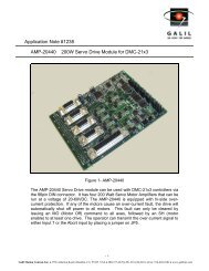
Chapter 5 SDM-20240/20242<br />
______________________________________________________________________________<br />
Introduction<br />
The SDM-20240 <strong>and</strong> SDM-20242 are stepper driver modules capable of driving up to four bipolar<br />
two-phase stepper motors. The current is selectable with options of 0.5, 0.75, 1.0, <strong>and</strong> 1.4<br />
Amps/Phase. The SDM-20242 is the replacement for the SDM-20240 as of December 2006.<br />
Note: Do not “hot swap” the motor power connections. If the amp is enabled when the motor<br />
connector is connected or disconnected, damage to the amplifier can occur. <strong>Galil</strong> recommends<br />
powering the controller <strong>and</strong> amplifier down before changing the connector.<br />
Figure 12 SDM-20240 shown mounted to a <strong>DMC</strong>-2143-DIN-DC24<br />
<strong>DMC</strong>-<strong>21x3</strong> Accessories Chapter 5 SDM-20240/20242• 27
Electrical Specifications<br />
Layout<br />
DC Supply Voltage: 12-30 VDC<br />
Max Drive Current (per axis) 1.4 Amps (jumper-settable)<br />
Max Step Frequency 3 MHz<br />
Motor Type Bipolar 2 phase<br />
Drawing Not to Scale. For Reference Only. Dimensions are in inches<br />
Figure 13 SDM-20240 Dimensions<br />
Overall Dimensions: 4.25” x 3.70”<br />
28 • Chapter 5 SDM-20240/20242 <strong>DMC</strong>-<strong>21x3</strong> Accessories
Pinout<br />
Figure 14 SDM-20242 Layout<br />
For connector dimensions, see SDM-20240 drawing above<br />
J2 - Motor Output X (4pin Molex) J3 - Motor Output Y (4pin Molex)<br />
1 XMOA+ 1 YMOA+<br />
2 XMOA- 2 YMOA-<br />
3 XMOB+ 3 YMOB+<br />
4 XMOB- 4 YMOB-<br />
J4 - Motor Output Z (4pin Molex) J5 - Motor Output W (4pin Molex)<br />
1 ZMOA+ 1 WMOA+<br />
2 ZMOA- 2 WMOA-<br />
3 ZMOB+ 3 WMOB+<br />
4 ZMOB- 4 WMOB-<br />
<strong>DMC</strong>-<strong>21x3</strong> Accessories Chapter 5 SDM-20240/20242• 29
J6 - X-axis 9-pin Male D-sub J7 Y-axis 9-pin Male D-sub<br />
1 Forward limit X 1 Forward limit Y<br />
2 Home X 2 Home Y<br />
3 5V 3 5V<br />
4 A- X 4 A- Y<br />
5 B- X 5 B- Y<br />
6 Reverse limit X 6 Reverse limit Y<br />
7 Ground 7 Ground<br />
8 A+ X 8 A+ Y<br />
9 B+ X 9 B+ Y<br />
J8 Z-axis 9-pin Male D-sub J9 W-axis 9-pin Male D-sub<br />
1 Forward limit Z 1 Forward limit W<br />
2 Home Z 2 Home W<br />
3 5V 3 5V<br />
4 A- Z 4 A- W<br />
5 B- Z 5 B- W<br />
6 Reverse limit Z 6 Reverse limit W<br />
7 Ground 7 Ground<br />
8 A+ Z 8 A+ W<br />
9 B+ Z 9 B+ W<br />
J11 I/O 25-pin Male D-sub 13 NC<br />
1 Ground 14 5V<br />
2 Latch X/Input 1 15 Latch Y/Input 2<br />
3 Latch Z/Input 3 16 Latch W/Input 4<br />
4 Input 5 17 Input 6<br />
5 Input 7 18 Input 8<br />
6 Abort 19 Encoder-compare output<br />
7 Output 1 20 Output 2<br />
8 Output 3 21 Output 4<br />
9 Output 5 22 Output 6<br />
10 Output 7 23 Output 8<br />
11 Ground 24 5V<br />
12 Reset 25 Error<br />
J1 Power<br />
1 +V (12V-30V) 3 +V (12V-30V)<br />
2 Ground 4 Ground<br />
30 • Chapter 5 SDM-20240/20242 <strong>DMC</strong>-<strong>21x3</strong> Accessories
JP8 – Servo Motor Signals<br />
1 XAEN (X Amp Enable)<br />
2 XMCM (X Motor CMD)<br />
3 YAEN (Y Amp Enable)<br />
4 YMCM (Y Motor CMD)<br />
5 ZAEN (Z Amp Enable)<br />
6 ZMCM (Z Motor CMD)<br />
7 WAEN (W Amp Enable)<br />
8 WMCM (W Motor CMD)<br />
9 GND<br />
10 GND<br />
Mating Connectors<br />
Connector Terminal Pins<br />
J1: Power Molex: 26-03-4041 Molex: 08-50-0189<br />
J2-J5: Motor Leads Molex: 22-01-3047 Molex: 08-50-0114<br />
______________________________________________________________________________<br />
Configurations for SDM-20240 & SDM-20242<br />
The SDM-20240 & 20242 have jumpers for setting different functions on the amplifier. The<br />
output current per phase can be set as noted in the table below to 0.5, 0.75, 1.0, or 1.4<br />
Amps/phase. Jumpers are also used to control the current level when the motor is holding position<br />
<strong>and</strong> the degree of microstepping. The SDM-20242 has additional jumpers for extra functionality<br />
The following paragraphs give the details of the jumper settings.<br />
Motor Current Setting<br />
Set the Current Reference jumpers for each axis to determine the maximum (peak) output current<br />
for each motor. The axes X,Y,Z, <strong>and</strong> W apply to jumpers JP3, JP4, JP5, <strong>and</strong> JP6 (SDM-20240)<br />
or JPX1, JPY1, JPZ1, <strong>and</strong> JPW1(SDM-20242) respectively. Four options are available for each<br />
axis: 0.5A, 0.75A, 1.0A, <strong>and</strong> 1.4 A. In figure below, the X-axis is configured for 0.5A, the Y axis<br />
as 0.75A, the Z-axis with 1.0 A, <strong>and</strong> the W axis for 1.4 A. (Note: when using the 1.4 A setting, a<br />
cooling fan or adequate air flow may be required.)<br />
<strong>DMC</strong>-<strong>21x3</strong> Accessories Chapter 5 SDM-20240/20242• 31
XREF YREF ZREF WREF<br />
0.5A<br />
.75A<br />
1.0A<br />
1.4A<br />
JP3 JP4 JP5<br />
SDM-20240<br />
32 • Chapter 5 SDM-20240/20242 <strong>DMC</strong>-<strong>21x3</strong> Accessories<br />
JP6<br />
Figure 15 Current Limit Jumper Configuration<br />
Low Current Setting (JP1)<br />
The LC jumper <strong>and</strong> associated “LC” comm<strong>and</strong> have three possible configurations for both the<br />
SDM-20240 <strong>and</strong> SDM-20242:<br />
LC comm<strong>and</strong> set to 1 <strong>and</strong> LC jumper ON – causes motor to use 25% (50% rev A & B) of<br />
peak current while at a “resting” state (profiler is not comm<strong>and</strong>ing motion). This is the<br />
recommended configuration to minimize heat generation <strong>and</strong> power consumption.<br />
LC comm<strong>and</strong> set to 1 <strong>and</strong> LC jumper OFF – turns amplifiers off when at “rest” (not<br />
comm<strong>and</strong>ing motion).<br />
LC jumper ON or OFF <strong>and</strong> LC comm<strong>and</strong> set to 0 (default). Full current to drive even<br />
when at rest. Proper heat dissipation is critical if using LC0.<br />
The LC comm<strong>and</strong> must be entered after MT-2,-2,-2,-2. LC should be set for each axis – so<br />
LC1,1,1,1 will cause all axes to operate in “Low Current” mode.<br />
Low Current Setting SDM-20240/20242: LC n,n,n,n,n,n,n,n<br />
n = 0 100%<br />
n = 1 25% * / 0%<br />
* LC function for SDM 20240 requires jumper<br />
installation at JP1, else 0% current occurs.<br />
SDM-20240 Half Step jumper (JP1) – determines whether pulses from the<br />
controller are interpreted by the Driver chips as whole or half step increments.<br />
Half Step Jumper On = Half step<br />
Half Step Jumper Off = Full step
______________________________________________________________________________<br />
Additional Settings for SDM-20242<br />
Micro Step jumpers (JP1)<br />
Determines whether pulses from the controller are interpreted by the Driver chips as whole, half,<br />
or micro-step increments.<br />
No Jumper = Full step 1<br />
M1 ON only = Half step<br />
M2 ON only = 1/4 th step<br />
M1 <strong>and</strong> M2 ON = 1/16 th step<br />
1<br />
When running in full step mode – the current to the motor is 70% of maximum. All micro-step<br />
settings are able to deliver full current<br />
Protection Circuitry <strong>and</strong> Error LED<br />
The SDM-20242 has short circuit protection circuitry as well as under/over voltage <strong>and</strong> over<br />
temperature protection. Here is a list of possible reasons for the Error LED to turn on <strong>and</strong> stop all<br />
motors from operating:<br />
• If the motor leads are shorted together, or shorted to ground<br />
• Power is applied to the controller before the driver board<br />
When the LED comes on, the error has to be cleared by issuing MO;SH. If the controller is in<br />
LC*=1 mode, an LC*=0;LC*=1 comm<strong>and</strong> is required to clear the error condition.<br />
ELO (Emergency Lock Out)<br />
The Emergency Lock Out jumper (ELO on JP1) is a jumper setting on the SDM-20242 which<br />
configures the driver’s behavior when the abort line goes low. With the jumper absent (default),<br />
the behavior of the motors is subject to the OE comm<strong>and</strong>. When the jumper is installed, the<br />
amplifiers will be immediately shut down at a hardware level (bypasses the controller firmware).<br />
When the ELO jumper is installed, the OE comm<strong>and</strong> should be set to 1. To recover, issue<br />
MO;SH.<br />
Fault Output from SDM-20242<br />
The fault output jumper allows the user to choose to bring out the amplifier’s error signal to either<br />
the Abort line or Input 7 of the controller. With no jumper – the fault signal is not connected to<br />
the controller at all. If a jumper is placed between the center pin <strong>and</strong> towards the side that says<br />
7_IN – then input 7 is used. Conversely, if the jumper is placed between the center pin <strong>and</strong> the<br />
side that says ABORT – the Abort line is jumpered to the fault output.<br />
JP5 FLT<br />
7_IN ABORT<br />
<strong>DMC</strong>-<strong>21x3</strong> Accessories Chapter 5 SDM-20240/20242• 33
THIS PAGE LEFT BLANK INTENTIONALLY<br />
34 • Chapter 5 SDM-20240/20242 <strong>DMC</strong>-<strong>21x3</strong> Accessories
Chapter 6 AMP-20341<br />
______________________________________________________________________________<br />
Introduction<br />
The AMP-20341 contains four linear drives for operating small brush-type servo motors. The<br />
AMP-20341 requires a ± 12–30 DC Volt input.* Output power is 20 W per amplifier or 60 W<br />
total. The gain of each transconductance linear amplifier is 0.1 A/V at 1 A maximum current.<br />
The typical current loop b<strong>and</strong>width is 4 kHz. The AMP-20341 uses 15-pin D-sub connectors for<br />
encoder <strong>and</strong> limit connections on each axis <strong>and</strong> a 25-pin D-sub connector for I/O connections.<br />
Note: Do not “hot swap” the motor power connections. If the amp is enabled when the motor<br />
connector is connected or disconnected, damage to the amplifier can occur. <strong>Galil</strong> recommends<br />
powering the controller <strong>and</strong> amplifier down before changing the connector.<br />
* The AMP-20341 replaces the AMP-20340, which accepted a single voltage supply<br />
Figure 16 ICM-20100 (left) <strong>and</strong> AMP-20341 (right) shown mounted with <strong>DMC</strong>-2183-DIN<br />
<strong>DMC</strong>-<strong>21x3</strong> Accessories Chapter 6 AMP-20341• 35
Electrical Specifications<br />
Layout<br />
DC Supply Voltage: +/-12-30 VDC (bipolar)<br />
Max Current (per axis) 1.0 Amps<br />
<strong>Amplifier</strong> gain: 0.1 A/V<br />
Power output (per channel): 20 W<br />
Total max. power output: 60 W<br />
Figure 17 AMP-20341 Hole Dimensions<br />
36 • Chapter 6 AMP-20341 <strong>DMC</strong>-<strong>21x3</strong> Accessories
Pinout<br />
Pin J3 J4 J5 J6<br />
1 Forward Limit X Forward Limit Y Forward Limit Z Forward Limit W<br />
2 Home X Home Y Home Z Home W<br />
3 5V 5V 5V 5V<br />
4 A-X A-Y A-Z A-W<br />
5 B-X B-Y B-Z B-W<br />
6 I-X I-Y I-Z I-W<br />
7 AA-X AA-Y AA-Z AA-W<br />
8 AB-X AB-Y AB-Z AB-W<br />
9 Reverse Limit X Reverse Limit Y Reverse Limit Z Reverse Limit W<br />
10 Ground Ground Ground Ground<br />
11 A+X A+Y A+Z A+W<br />
12 B+X B+Y B+Z B+W<br />
13 I+X I+Y I+Z I+W<br />
14 AA+X AA+Y AA+Z AA+W<br />
15 AB+X AB+Y AB+Z AB+W<br />
JX - Motor Output X (2pin Molex) JY - Motor Output Y (2pin Molex)<br />
JX1 XMO+ JY1 YMO+<br />
JX2 XMO- JY2 YMO-<br />
JZ - Motor Output Z (2pin Molex) JW - Motor Output W (2pin Molex)<br />
JZ1 ZMO+ JW1 WMO+<br />
JZ2 ZMO- JW2 WMO-<br />
1 Ground 8 Output 3<br />
J2 I/O (25 Pin D-sub)<br />
15 Latch Y/Input 2 22 Output 6<br />
2 Latch X/Input 1 9 Output 5 16 Latch W/Input 4 23 Output 8<br />
3 Latch Z/Input 3 10 Output 7 17 Input 6 24 5V<br />
4 Input 5 11 Ground 18 Input 8 25 Error Output *<br />
5 Input 7 12 Reset * 19 Encoder compare output<br />
6 Abort* 13 NC 20 Output 2<br />
7 Output 1 14 5V 21 Output 4 * Active Low<br />
J9 Power<br />
1 +V (12 to 30V)<br />
2 Ground<br />
3 -V (-12 to -30V)<br />
<strong>DMC</strong>-<strong>21x3</strong> Accessories Chapter 6 AMP-20341• 37
J8 External <strong>Amplifier</strong><br />
1 Amp Enable X 6 Motor Comm<strong>and</strong><br />
2 Motor Comm<strong>and</strong> X 7 Amp Enable W<br />
3 Amp Enable Y 8 Motor Comm<strong>and</strong> W<br />
4 Motor Comm<strong>and</strong> Y 9 Ground<br />
5 Amp Enable Z 10 Ground<br />
Mating Connectors<br />
Connector Terminal Pins<br />
J9: Power Molex: 26-03-4030 Molex: 08-50-0189<br />
JX - JW: Motor Leads Molex: 22-01-3027 Molex: 08-50-0114<br />
38 • Chapter 6 AMP-20341 <strong>DMC</strong>-<strong>21x3</strong> Accessories
Chapter 7 AMP-20440/20420<br />
_____________________________________________________________<br />
Introduction<br />
The AMP-20420 <strong>and</strong> AMP-20440 are brush style amplifiers with a power capacity of 200 Watts<br />
per channel. The amplifier is operational from 18-60 VDC. The amplifier is a transconductance<br />
amplifier <strong>and</strong> will supply a current proportional to a given comm<strong>and</strong> signal. The amplifier<br />
includes protection against over voltage <strong>and</strong> over current. The controller below is shown<br />
connecting with an AMP-20440.<br />
Note: Do not “hot swap” the motor power connections. If the amp is enabled when the motor<br />
connector is connected or disconnected, damage to the amplifier can occur. <strong>Galil</strong> recommends<br />
powering the controller <strong>and</strong> amplifier down before changing the connector.<br />
Figure 18 AMP-20440 shown mounted to a <strong>DMC</strong>-2143-DIN-DC24<br />
<strong>DMC</strong>-<strong>21x3</strong> Accessories Chapter 7 AMP-20440/20420• 39
Electrical Specifications<br />
Layout<br />
DC Supply Voltage: 18-60 VDC<br />
Max Current: 3.3 Amps (continuous <strong>and</strong> peak)<br />
PWM Frequency: 60 kHz<br />
Minimum Load Inductance: 0.5 mH<br />
Over-Voltage Threshold (OV): 69 volts (resets at 66 volts)<br />
Drawing Not to Scale. For Reference Only. Dimensions are inches.<br />
Figure 19 AMP-20440 Dimensions<br />
Overall Dimensions: 4.85” x 3.70”<br />
40 • Chapter 7 AMP-20440/20420 <strong>DMC</strong>-<strong>21x3</strong> Accessories
Pinout<br />
J4 X-axis 15-pin Hi-density Female D-sub<br />
1 I+ X<br />
2 B+ X<br />
3 A+ X<br />
4 AB+ X<br />
5 Ground<br />
6 I- X<br />
7 B- X<br />
8 A- X<br />
9 AA- X<br />
10 Forward Limit X<br />
11 AA+ X<br />
12 AB- X<br />
13 Home X<br />
14 Reverse Limit X<br />
15 5V<br />
J6 Z-axis 15-pin Hi-density Female D-sub<br />
1 I+ Z<br />
2 B+ Z<br />
3 A+ Z<br />
4 AB+ Z<br />
5 Ground<br />
6 I- Z<br />
7 B- Z<br />
8 A- Z<br />
9 AA- Z<br />
10 Forward Limit Z<br />
11 AA+ Z<br />
12 AB- Z<br />
13 Home Z<br />
14 Reverse Limit Z<br />
15 5V<br />
J5 Y-axis 15-pin Hi-density Female D-sub<br />
1 I+ Y<br />
2 B+ Y<br />
3 A+ Y<br />
4 AB+ Y<br />
5 Ground<br />
6 I- Y<br />
7 B- Y<br />
8 A- Y<br />
9 AA- Y<br />
10 Forward Limit Y<br />
11 AA+ Y<br />
12 AB- Y<br />
13 Home Y<br />
14 Reverse Limit Y<br />
15 5V<br />
J7 W-axis 15-pin Hi-density Female D-sub<br />
1 I+ W<br />
2 B+ W<br />
3 A+ W<br />
4 AB+ W<br />
5 Ground<br />
6 I- W<br />
7 B- W<br />
8 A- W<br />
9 AA- W<br />
10 Forward Limit W<br />
11 AA+ W<br />
12 AB- W<br />
13 Home W<br />
14 Reverse Limit W<br />
15 5V<br />
<strong>DMC</strong>-<strong>21x3</strong> Accessories Chapter 7 AMP-20440/20420• 41
J1 Power 4-pin 13 Sign/Dir Z<br />
1 VM+ 18-60 VDC 14 Sign/Dir W<br />
2 Ground 15 PWM/Step W<br />
3 VM+ 18-60 VDC 16 W-axis AmpEnable (RevD <strong>and</strong> greater)<br />
4 Ground 17 Z-axis AmpEnable (RevD <strong>and</strong> greater)<br />
Mating Connector AMP 770849-4 18 Output 7<br />
Mating Connector Pins AMP 770476-1 19 Output 4<br />
20 Output 1<br />
JX1 Motor Output 2-pin Molex 21 Output 3<br />
1 XMO- 22 Input 7<br />
2 XMO+ 23 Latch W / Input 4<br />
JY1 Motor Output 2-pin Molex 25 NC<br />
24 Latch X / Input 1<br />
1 YMO- 26 Motor Comm<strong>and</strong> X<br />
2 YMO+ 27 Motor Comm<strong>and</strong> Y<br />
28 Motor Comm<strong>and</strong> Z<br />
JZ1 Motor Output 2-pin Molex 29 Motor Comm<strong>and</strong> W<br />
1 ZMO- 30 Error Output*<br />
2 ZMO+ 31 NC<br />
42 • Chapter 7 AMP-20440/20420 <strong>DMC</strong>-<strong>21x3</strong> Accessories<br />
32 5V<br />
JW1 Motor Output 2-pin Molex 33 5V<br />
1 WMO- 34 Ground<br />
2 WMO+ 35 Ground<br />
Mating Connector Molex 26-03-4020 36 Input 8<br />
Mating Connector Pins Molex 08-50-0189 37 Input 5<br />
J3 I/0 44-pin Hi-density Female D-sub 39 NC<br />
38 Latch Y / Input 2<br />
1 NC 40 X-axis AmpEnable (RevD <strong>and</strong> greater)<br />
2 Output 6 41 PWM/Step X<br />
3 Output 8 42 PWM/Step Y<br />
4 Output 5 43 PWM/Step Z<br />
5 Output 2 44 Reset*<br />
6 Abort* (see Appendix A) *Active Low Signal<br />
7 Input 6<br />
8 Latch Z / Input 3<br />
9 Y-axis AmpEnable (RevD <strong>and</strong> greater)<br />
10 Encoder-Compare Output<br />
11 Sign/Dir X<br />
12 Sign/Dir Y
Over-Voltage Protection<br />
The AMP-204x0 is protected against over voltage. If the supply voltage to the amplifier<br />
exceeds 69 V, the over voltage protection will take effect. The yellow over voltage LED will be<br />
lit on the amplifier until the voltage drops below 66 V. It is possible to get into this condition if<br />
the power supply voltage is too high, or if the voltage level is raised due to regeneration. If you<br />
have very high inertial loads (which may cause regeneration), you may consider using a shunt<br />
regulator such as the SR-19900 supplied by <strong>Galil</strong>. Another important issue to consider is the<br />
level of the over voltage protection. You should set the shunt regulator at a voltage level which<br />
will still allow for proper operation of the power supply. Note that if you are using the -DC24<br />
option from <strong>Galil</strong>, the DC-DC converter is capable of receiving voltages up to 36 V. If you<br />
need a shunt regulator, you should set the device to limit the voltage to a value less than 36 V.<br />
If you are using the -DC48 option, the voltage should be limited to 66 V <strong>and</strong> it is recommended<br />
that you use a supply of 60V or less.<br />
Over-Current Protection<br />
The controller also has protection against over current. Over current will cause the amplifier to<br />
be disabled, <strong>and</strong> can be enabled again from the controller by issuing the MO <strong>and</strong> then SH<br />
comm<strong>and</strong>. If you see that the red over current LED is lit on the amplifier, there is a problem<br />
with either your system or the amplifier. The most likely reason is because of a short between<br />
the motor phases or between the motor phases <strong>and</strong> ground. This indicates either a wiring<br />
problem, or a faulty motor.<br />
Please review the table below to configure the options for the over current signal. If you choose<br />
the option of connecting the over current signal to the abort line, all axes in motion <strong>and</strong> the<br />
controller’s application program will be aborted. If you choose to transmit the signal to input 7,<br />
then an application program can be set to interrupt on this input, <strong>and</strong> run a user defined program.<br />
For further information on using the abort, or the input interrupt routines, refer to the user<br />
manual supplied with the motion controller.<br />
No jumper (factory default): causes the controller to<br />
take no action when an over-current condition occurs<br />
(AMP-204x0 amplifier still disables).<br />
OC-IN7: Place jumper between OC <strong>and</strong> IN7 to transmit<br />
over-current condition to the controller’s General-Purpose<br />
Digital Input 7. Use the AE comm<strong>and</strong> to allow<br />
#AMPERR to run <strong>and</strong> TA to report status<br />
OC-ABRT: Place jumper between OC <strong>and</strong> ABRT to<br />
transmit over-current condition to the controller’s Abort<br />
Input.<br />
Figure 20 AMP-204x0 Overcurrent jumper configurations<br />
<strong>DMC</strong>-<strong>21x3</strong> Accessories Chapter 7 AMP-20440/20420• 43
Abort Input Options<br />
See Appendix A.<br />
44 • Chapter 7 AMP-20440/20420 <strong>DMC</strong>-<strong>21x3</strong> Accessories
Chapter 8 ICM-20500<br />
_________________________________________________________________<br />
Introduction<br />
The ICM-20500 provides a screw terminal interface for the AMP-205x0. The unit also provides optical<br />
isolation on digital inputs <strong>and</strong> outputs to interface with up to 24V I/O. The first four outputs are high<br />
power outputs capable of providing up to 500 mA at up to 24 VDC.<br />
The ICM-20500 is also available with D-type connectors instead of screw terminals (order as ICM-<br />
20500-DTYPE). This provides optical isolation of the I/O when using an AMP-205x0. The D-type<br />
connectors include four 15-pin high density connectors <strong>and</strong> one 44-pin high-density connector. The<br />
pinout of the 15-pin connectors is the same as the AMP-205x0. The 44-pin connections are the same<br />
except for the following four signals:<br />
Pin 9 Output Supply<br />
Pin 25 Input Common (INCOM)<br />
Pin 39 Output Return<br />
Pin 40 Limit Switch Common (LSCOM)<br />
Note that the ability to connect to external amplifiers on X <strong>and</strong> Y is lost when using an<br />
ICM-20500-DTYPE.<br />
Figure 21 ICM-20500 shown mounted to a <strong>DMC</strong>-2143 <strong>and</strong> AMP-20540<br />
<strong>DMC</strong>-<strong>21x3</strong> Accessories Chapter 8 ICM-20500• 45
Electrical Specifications<br />
Layout<br />
Input Common Max Voltage 28 VDC<br />
Output Common Max Voltage 28 VDC<br />
Max Drive Current per Output 0.5 A (outputs 1-4), 25 mA (outputs 5-8)<br />
Minimum Current to turn on Inputs 1 mA<br />
Drawing Not to Scale. For Reference Only. Dimensions are inches.<br />
Figure 22 ICM-20500 Dimensions<br />
Overall Dimensions: 8.12” x 4.20”<br />
46 • Chapter 8 ICM-20500 <strong>DMC</strong>-<strong>21x3</strong> Accessories
Pinout<br />
ICM-20500 (st<strong>and</strong>ard product with screw terminals)<br />
1 W Hall Phase C 37 Y Aux Encoder A + 73 Digital Output 6 (25 mA)<br />
2 + 5 V (Power output) 38 Y Aux Encoder A - 74 Digital Output 7 (25 mA)<br />
3 GND (Power return) 39 Y Aux Encoder B + 75 Digital Output 8 (25 mA)<br />
4 W Aux Encoder B - 40 Y Main Encoder B - 76 Digital Output 3 (0.5 A)<br />
5 W Hall Phase A 41 Y Main Encoder I + 77 Digital Output 4 (0.5 A)<br />
6 W Hall Phase B 42 Y Main Encoder I - 78 Digital Output 5 (25 mA)<br />
7 W Aux Encoder A + 43 Y Main Encoder A + 79 + 5 V (Power output)<br />
8 W Aux Encoder A - 44 Y Main Encoder A - 80 Digital Output 1 (0.5 A)<br />
9 W Aux Encoder B + 45 Y Main Encoder B + 81 Digital Output 2 (0.5 A)<br />
10 W Main Encoder B - 46 X Hall Phase C 82 Digital Input 8<br />
11 W Main Encoder I + 47 + 5 V (Power output) 83 INCOM<br />
12 W Main Encoder I - 48 GND (Power return) 84 GND (Power return)<br />
13 W Main Encoder A + 49 X Aux Encoder B - 85 Digital Input 5<br />
14 W Main Encoder A - 50 X Hall Phase A 86 Digital Input 6<br />
15 W Main Encoder B + 51 X Hall Phase B 87 Digital Input 7<br />
16 Z Hall Phase C 52 X Aux Encoder A + 88 Y Latch / DI 2<br />
17 + 5 V (Power output) 53 X Aux Encoder A - 89 Z Latch / DI 3<br />
18 GND (Power return) 54 X Aux Encoder B + 90 W Latch / DI 4<br />
19 Z Aux Encoder B - 55 X Main Encoder B - 91 LSCOM<br />
20 Z Hall Phase A 56 X Main Encoder I + 92 Abort Input<br />
21 Z Hall Phase B 57 X Main Encoder I - 93 X Latch / DI 1<br />
22 Z Aux Encoder A + 58 X Main Encoder A + 94 W Home Input<br />
23 Z Aux Encoder A - 59 X Main Encoder A - 95 W Reverse Limit<br />
24 Z Aux Encoder B + 60 X Main Encoder B + 96 W Forward Limit<br />
25 Z Main Encoder B - 61 Y Motor Comm<strong>and</strong> 97 Z Home Input<br />
26 Z Main Encoder I + 62 X Amp Enable 98 Z Reverse Limit<br />
27 Z Main Encoder I - 63 X Motor Comm<strong>and</strong> 99 Z Forward Limit<br />
28 Z Main Encoder A + 64 Z Amp Enable 100 Y Home Input<br />
29 Z Main Encoder A - 65 Z Motor Comm<strong>and</strong> 101 Y Reverse Limit<br />
30 Z Main Encoder B + 66 Y Amp Enable 102 Y Forward Limit<br />
31 Y Hall Phase C 67 + 5 V (Power output) 103 X Home Input<br />
32 + 5 V (Power output) 68 W Amp Enable 104 X Reverse Limit<br />
33 GND (Power return) 69 W Motor Comm<strong>and</strong> 105 X Forward Limit<br />
34 Y Aux Encoder B - 70 Output Supply 106 Output Compare<br />
35 Y Hall Phase A 71 Output Return 107 Error (Output)<br />
36 Y Hall Phase B 72 GND (Power return) 108 Reset (Input)<br />
ICM-20500-DTYPE (D-shell connectors <strong>and</strong> no screw terminals)<br />
The pinout of 15-pin connectors is the same as the AMP-205x0. The 44-pin connections are the<br />
same except for the following four signals:<br />
Pin 9 Output Supply<br />
Pin 25 Input Common (INCOM)<br />
Pin 39 Output Return<br />
Pin 40 Limit Switch Common (LSCOM)<br />
<strong>DMC</strong>-<strong>21x3</strong> Accessories Chapter 8 ICM-20500• 47
Configuration<br />
Limit<br />
Switch<br />
Common<br />
LSCOM<br />
Input<br />
Common<br />
Voltage<br />
INCOM<br />
FLSX RLSX HOMEX FLSY RLSY HOMEY<br />
Additional Limit<br />
Switches(Dependent on<br />
Number of Axes)<br />
IN1 IN2 IN3 IN4 IN5 IN6 IN7 IN8 ABORT<br />
(XLATCH) (YLATCH) (ZLATCH) (W LATCH)<br />
Figure 23 ICM-20500 Digital Inputs<br />
The schematic above shows the digital input configuration. For digital inputs 1 to 8, INCOM<br />
connects to the positive (+) terminal of an external DC supply for a sourcing configuration. For<br />
a sinking configuration, the negative (-) supply terminal is connected instead. The same<br />
approach is applied to the Home <strong>and</strong> Limit switch inputs with LSCOM.<br />
On the digital outputs, the first<br />
ICM-20500<br />
ICM-20<br />
Machine<br />
four outputs (Outputs 1 to 4)<br />
10K<br />
OUTSUP (+) are high power outputs capable<br />
of providing up to 500 mA at<br />
up to 24 VDC. An external<br />
DC supply must be connected<br />
RP Out<br />
between Output Supply <strong>and</strong><br />
Output Return. The other four<br />
outputs (Outputs 5 to 8) are<br />
Load<br />
opto-isolated <strong>and</strong> can deliver<br />
up to 25 mA at up to 24 VDC.<br />
The diagram refers only to<br />
outputs 1 to 4. On outputs 5 to<br />
8, there is no FET on final<br />
OUTRET ( -)<br />
stage of the output, only the<br />
Figure 24 High Power Outputs<br />
opto-isolator.<br />
The polarity of outputs 1-4<br />
may be reversed by flipping RP11 180 degrees. The polarity of outputs 5-8 may be reversed by<br />
flipping RP12 180 degrees.<br />
RPOUT<br />
5V or GND<br />
SB n = 5V<br />
48 • Chapter 8 ICM-20500 <strong>DMC</strong>-<strong>21x3</strong> Accessories
Chapter 9 AMP-20540/20520<br />
____________________________________________________________________________<br />
Introduction<br />
The AMP-20540 (four-axis) <strong>and</strong> AMP-20520 (two-axis) are multi-axis brush/brushless<br />
amplifiers that are capable of h<strong>and</strong>ling 500 watts of continuous power per axis. The AMP-<br />
20540/20520 Brushless drive modules are connected to a <strong>DMC</strong>-<strong>21x3</strong> controller via the 96 pin<br />
DIN connector. The st<strong>and</strong>ard amplifier accepts DC supply voltages from 18-60 VDC. Note<br />
that the -DC48 option is only rated to 72 VDC. The 80 V option requires the user to provide +/-<br />
12 V <strong>and</strong> 5 V supplies to the controller separate from the amplifier. If higher voltages are<br />
required, please contact <strong>Galil</strong>. Like the DB-28040, the AMP-205x0 family provides for the<br />
addition of 8 analog input to the <strong>DMC</strong>-<strong>21x3</strong>. The analog inputs accept +/- 10 V input <strong>and</strong> have<br />
a resolution of 12 bits; a 16 bit option is available.<br />
Note: Do not “hot swap” the motor power connections. If the amp is enabled when the motor<br />
connector is connected or disconnected, damage to the amplifier can occur. <strong>Galil</strong> recommends<br />
powering the controller <strong>and</strong> amplifier down before changing the connector.<br />
Figure 25 AMP-20540<br />
<strong>DMC</strong>-<strong>21x3</strong> Accessories Chapter 9 AMP-20540/20520• 49
Electrical Specifications<br />
Layout<br />
The amplifier is a brush/brushless trans-conductance PWM amplifier. The amplifier operates in<br />
torque mode, <strong>and</strong> will output a motor current proportional to the comm<strong>and</strong> signal input.<br />
Supply Voltage: 18-60 VDC (Up to 80V optional)<br />
Continuous Current: 7 Amps<br />
Peak Current 10 Amps<br />
Nominal <strong>Amplifier</strong> Gain 0.4, 0.7, <strong>and</strong> 1.0 A/V<br />
Switching Frequency 60 kHz (up to 140 kHz available-contact <strong>Galil</strong>)<br />
Minimum Load Inductance: 0.5 mH (low inductance option available)<br />
Brushless Motor Commutation angle 120° (60° option available)<br />
Drawing Not to Scale. For Reference Only. Dimensions are inches.<br />
Figure 26 AMP-20540 Dimensions<br />
Overall Dimensions: 6.92” x 4.85”<br />
50 • Chapter 9 AMP-20540/20520 <strong>DMC</strong>-<strong>21x3</strong> Accessories
Pinout<br />
J4 - X-axis 15-pin HD Female D-sub J5 - Y-axis 15-pin HD Female D-sub<br />
01 I+ X 01 I+ Y<br />
02 B+ X 02 B+ Y<br />
03 A+ X 03 A+ Y<br />
04 AB+ X 04 AB+ Y<br />
05 GND 05 GND<br />
06 I- X 06 I- Y<br />
07 B- X 07 B- Y<br />
08 A- X 08 A- Y<br />
09 AA- X 09 AA- Y<br />
10 Hall X A 10 Hall Y A<br />
11 AA+ X 11 AA+ Y<br />
12 AB- X 12 AB- Y<br />
13 Hall X B 13 Hall Y B<br />
14 Hall X C 14 Hall Y C<br />
15 5V 15 5V<br />
J6 - Z-axis 15-pin HD Female D-sub J7 - W-axis 15-pin HD Female D-sub<br />
01 I+ Z 01 I+ W<br />
02 B+ Z 02 B+ W<br />
03 A+ Z 03 A+ W<br />
04 AB+ Z 04 AB+ W<br />
05 GND 05 GND<br />
06 I- Z 06 I- W<br />
07 B- Z 07 B- W<br />
08 A- Z 08 A- W<br />
09 AA- Z 09 AA- W<br />
10 Hall Z A 10 Hall W A<br />
11 AA+ Z 11 AA+ W<br />
12 AB- Z 12 AB- W<br />
13 Hall Z B 13 Hall W B<br />
14 Hall Z C 14 Hall W C<br />
15 5V 15 5V<br />
<strong>DMC</strong>-<strong>21x3</strong> Accessories Chapter 9 AMP-20540/20520• 51
JX1 - Motor Output X (4-pin ) JY1 - Motor Output Y (4-pin)<br />
NC NC<br />
2 X axis phase A 2 Y axis phase A<br />
3 X axis phase C 3 Y axis phase C<br />
4 X axis phase B 4 Y axis phase B<br />
JZ1 - Motor Output Z (4-pin) JW1 - Motor Output W (4-pin)<br />
NC NC<br />
2 Z axis phase A 2 W axis phase A<br />
3 Z axis phase C 3 W axis phase C<br />
4 Z axis phase B 4 W axis phase B<br />
J3 I/O 44-pin HD Female D-sub<br />
01 PWM/MCMD Z 23 W Latch/Input 4<br />
02 Output 6 24 X Latch/Input 1<br />
03 Output 8 25 PWM/MCMD X<br />
04 Output 5 26 X Home<br />
05 Output 2 27 Y Home<br />
06 Abort (see Appendix A) 28 Z Home<br />
07 Input 6 29 W Home<br />
08 Z Latch/Input 3 30 Error Out<br />
09 SIGN/AEN Y 31 PWM/MCMD W<br />
10 Output Compare 32 5V<br />
11 Reverse Limit X 33 5V<br />
12 Reverse Limit Y 34 Ground<br />
13 Reverse Limit Z 35 Ground<br />
14 Reverse Limit W 36 Input 8<br />
15 Forward Limit W 37 Input 5<br />
16 SIGN/AEN W 38 Y Latch/Input 2<br />
17 SIGN/AEN Z 39 PWM/MCMD Y<br />
18 Output 7 40 SIGN/AENX<br />
19 Output 4 41 Forward Limit X<br />
20 Output 1 42 Forward Limit Y<br />
21 Output 3 43 Forward Limit Z<br />
22 Input 7 44 Reset<br />
52 • Chapter 9 AMP-20540/20520 <strong>DMC</strong>-<strong>21x3</strong> Accessories
J1 Power (8-pin) J11 – Analog Input- 16 pin IDC Header<br />
1 Earth 01 GND 09 Analog Input 7<br />
2 +VDC (18V-60V) 02 GND 10 Analog Input 8<br />
3 +VDC (18V-60V) 03 Analog Input 1 11 GND<br />
4 +VDC (18V-60V) 04 Analog Input 2 12 GND<br />
5 GND 05 Analog Input 3 13 -12V<br />
6 GND 06 Analog Input 4 14 +12V<br />
7 GND 07 Analog Input 5 15 5V<br />
8 GND 08 Analog Input 6 16 GND<br />
Mating Connectors<br />
J1: DC Power<br />
Connector<br />
JX1, JY1, JZ1, <strong>and</strong><br />
JW1: 4-pin Motor<br />
Lead Connector<br />
Connector Terminal Pins<br />
8-pin Mini Universal<br />
MATE-N-LOK<br />
AMP# 770579-1 AMP# 170361-1<br />
4-pin Mini Universal<br />
MATE-N-LOK<br />
AMP# 172167-1 AMP# 170361-1<br />
<strong>DMC</strong>-<strong>21x3</strong> Accessories Chapter 9 AMP-20540/20520• 53
Operation<br />
Brushless Motor Setup<br />
Note: If you purchased a <strong>Galil</strong> motor with the amplifier, it is ready for use. No additional setup<br />
is necessary.<br />
To begin the setup of the brushless motor <strong>and</strong> amplifier, it is first necessary to have<br />
communications with the motion controller. Refer to the user manual supplied with your<br />
controller for questions regarding controller communications. It is also necessary to have the<br />
motor hardware connected <strong>and</strong> the amplifier powered to begin the setup phase. After the<br />
encoders <strong>and</strong> motor leads are connected, the controller <strong>and</strong> amplifier need to be configured<br />
correctly in software. Take all appropriate safety precautions. For example, set a small error<br />
limit (ER*=1000), a low torque limit (TL*=3), <strong>and</strong> set off on Error to 1 for all axes (OE*=1).<br />
Review the comm<strong>and</strong> reference <strong>and</strong> controller user manual for further details.<br />
There are 3 settings for the amplifier gain: 0.4 A/V, 0.7 A/V, <strong>and</strong> 1.0 A/V. If the gain is set to<br />
0.7 A/V, a torque limit of 3 (TLn=3) will allow the amplifier to output no more than 2.1 amps of<br />
current on the specified axis. The controller has been programmed to test whether the Hall<br />
commutation order is correct. To test the commutation for the X axis, issue the BS comm<strong>and</strong><br />
(BSX= n,m). The controller will attempt to move the motor through one revolution. If the<br />
motor is unable to move, the controller will return “unknown Hall transition”, check wiring, <strong>and</strong><br />
execute BS again’. It may be necessary to issue more voltage to create motion. The default for<br />
the BS comm<strong>and</strong> is BSn=0.25,1000 which will send 0.25 volts to the amplifier for 1 second.<br />
BSX=0.5,300 will issue 0.5 volts from the controller for 300 milliseconds. If the controller is<br />
able to move the motor <strong>and</strong> the Hall transitions are not correct, the controller will alert the<br />
operator <strong>and</strong> recommend which motor phases to change. For example, the controller might<br />
return “Wire A to Terminal B, Wire B to Terminal A.” If the controller finds that the<br />
commutation order is correct, but the motor would run away due to positive feedback, the<br />
controller will prompt the user to “Wire Phase B to C <strong>and</strong> C to B. Exchange Hall Sensors A <strong>and</strong><br />
B…”. After making any necessary changes to the motor phase wiring, confirm correct<br />
operation by reissuing the BS comm<strong>and</strong>. Once the axis is wired correctly, the controller is<br />
ready to perform closed-loop motion.<br />
Brushless <strong>Amplifier</strong> Software Setup<br />
Select the amplifier gain that is appropriate for the motor. The amplifier gain comm<strong>and</strong> (AG)<br />
can be set to 0, 1, or 2 corresponding to 0.4, 0.7, <strong>and</strong> 1.0 A/V. In addition to the gain, peak <strong>and</strong><br />
continuous torque limits can be set through TK <strong>and</strong> TL respectively. The TK <strong>and</strong> TL values are<br />
entered in volts on an axis by axis basis. The peak limit will set the maximum voltage that will<br />
be output from the controller to the amplifier. The continuous current will set what the<br />
maximum average current is over a one second interval. The following figure captured with<br />
WSDK is indicative of the operation of the continuous <strong>and</strong> peak operation. In this figure, the<br />
continuous limit was configured for 2 volts, <strong>and</strong> the peak limit was configured for 10 volts.<br />
54 • Chapter 9 AMP-20540/20520 <strong>DMC</strong>-<strong>21x3</strong> Accessories
Figure 27 Peak Current Operation (<strong>DMC</strong>-2143 <strong>and</strong> AMP-20540)<br />
With the AMP-20540 <strong>and</strong> 20520, the user is also given the ability to choose between normal<br />
<strong>and</strong> high current b<strong>and</strong>width (AU). In addition, the user can calculate what the b<strong>and</strong>width of the<br />
current loop is for their specific combination (AW). To select normal current loop gain for the<br />
X axis <strong>and</strong> high current loop gain for the Y axis, issue AU 0,1. The comm<strong>and</strong> AW is used to<br />
calculate the b<strong>and</strong>width of the amplifier using the basic amplifier parameters. To calculate the<br />
b<strong>and</strong>width for the X axis, issue AWX=v,l,n where v represents the DC voltage input to the card,<br />
l represents the inductance of the motor in millihenries, <strong>and</strong> n represents 0 or 1 for the AU<br />
setting.<br />
Note: For most applications, unless the motor has more than 5 mH of inductance with a 24V<br />
supply, or 10 mH of inductance with a 48 volts supply, the normal current loop b<strong>and</strong>width<br />
option should be chosen. AW will return the current loop b<strong>and</strong>width in Hertz.<br />
Brush <strong>Amplifier</strong> Operation<br />
The AMP-20540 <strong>and</strong> AMP-20520 also allow for brush operation. To configure an axis for<br />
brush-type operation, connect the 2 motor leads to Phase A <strong>and</strong> Phase B connections for the<br />
axis. Connect the encoders, homes, <strong>and</strong> limits as required. Set the controller into brush-axis<br />
operation by issuing BR n,n,n,n. By setting n=1, the controller will operate in brushed mode on<br />
that axis. For example, BR0,1,0,0 sets the Y-axis as brush-type, all others as brushless. If an<br />
axis is set to brush-type, the amplifier has no need for the Hall inputs. These inputs can<br />
subsequently be used as general-use inputs, queried with the QH comm<strong>and</strong>. The gain settings<br />
for the amplifier are identical for the brush <strong>and</strong> brushless operation. The gain settings can be set<br />
to 0.4, 0.7, or 1.0 A/V, represented by gain values of 0, 1, <strong>and</strong> 2 (e.g.. AG 0,0,2,1). The current<br />
loop gain AU can also be set to either 0 for normal, or 1 for high current loop gain.<br />
Using External <strong>Amplifier</strong>s<br />
The AMP-205x0 breaks out the step/direction or amplifier enable/motor comm<strong>and</strong> signals to<br />
control an external servo or stepper amplifier. For example, a machine might have two axes that<br />
use the AMP-20520 <strong>and</strong> two stepper axes that use external drivers. The pulse <strong>and</strong> direction<br />
signals are accessed through the high density 44-pin D-sub connector. The same connector pins<br />
are used to bring out the amplifier enable <strong>and</strong> motor comm<strong>and</strong> line. Which signals are brought<br />
<strong>DMC</strong>-<strong>21x3</strong> Accessories Chapter 9 AMP-20540/20520• 55
out is set via jumpers (see figure below). If no jumpers are installed (factory default), the<br />
corresponding pins on the 44-pin connector will be no-connects. In this example, W axis will<br />
output the motor comm<strong>and</strong> on pin 31 <strong>and</strong> amplifier enable on pin 16. The Z axis will output<br />
PWM (Step) <strong>and</strong> Sign (Direction) to the appropriate pins.<br />
Figure 28 The W-axis is configured for an external servo amplifier<br />
<strong>and</strong> Z for an external stepper amplifier<br />
Error Monitoring <strong>and</strong> Protection<br />
The amplifier is protected against over-voltage, under-voltage, over-temperature, <strong>and</strong> overcurrent<br />
for brush <strong>and</strong> brushless operation. The controller will also monitor for illegal Hall states<br />
(000 or 111 with 120° phasing). The controller will monitor the error conditions <strong>and</strong> respond as<br />
programmed in the application. The errors are monitored via the TA comm<strong>and</strong>. TA n may be<br />
used to monitor the errors with n = 0, 1, 2, or 3. The comm<strong>and</strong> will return an eight bit number<br />
representing specific conditions. TA0 will return errors with regard to under voltage, over<br />
voltage, over current, <strong>and</strong> over temperature. TA1 will return hall errors on the appropriate axes,<br />
TA2 will monitor if the amplifier current exceeds the continuous setting, <strong>and</strong> TA3 will return if<br />
the ELO has occurred as a result of a hard abort input.<br />
The user also has the option to include the special label #AMPERR in their program to h<strong>and</strong>le<br />
soft or hard errors. As long as a program is executing in thread zero, <strong>and</strong> the #AMPERR label is<br />
included, when an error is detected, the program will jump to the label <strong>and</strong> execute the user<br />
defined routine. Note that the TA comm<strong>and</strong> is a monitoring function only, <strong>and</strong> does not<br />
generate an error condition. The over voltage condition will not permanently shut down the<br />
amplifier or trigger the #AMPERR routine. The amplifier will be momentarily disabled; when<br />
the condition goes away, the amplifier will continue normal operation assuming it did not cause<br />
the position error to exceed the error limit.<br />
Hall Error Protection<br />
During normal operation, the controller should not have any Hall errors. Hall errors can be<br />
caused by a faulty Hall-effect sensor or a noisy environment. If at any time the Halls are in an<br />
invalid state, the appropriate bit of TA1 will be set. The state of the Hall inputs can also be<br />
monitored through the QH comm<strong>and</strong>. Hall errors will cause the amplifier to be disabled if OE 1<br />
is set, <strong>and</strong> will cause the controller to enter the #AMPERR subroutine if it is included in a<br />
running program.<br />
56 • Chapter 9 AMP-20540/20520 <strong>DMC</strong>-<strong>21x3</strong> Accessories
Under-Voltage Protection<br />
If the supply to the amplifier drops below 12 VDC, the amplifier will be disabled. The amplifier<br />
will return to normal operation once the supply is raised above the 12V threshold; bit 3 of the<br />
error status (TA0) will tell the user whether the supply is in the acceptable range.<br />
Over-Voltage Protection<br />
If the voltage supply to the amplifier rises above 68 VDC, then the amplifier will automatically<br />
disable. The amplifier will re-enable when the supply drops below 66 V. This error is<br />
monitored with bit 1 of the TA0 comm<strong>and</strong>. This protection is configurable to activate at 34V<br />
<strong>and</strong> re-enable at 33V by placing a jumper onto JP5.<br />
Over-Current Protection<br />
The amplifier also has circuitry to protect against over-current. If the total current from the<br />
supply exceeds 40 A, the amplifier will be disabled. The amplifier will not be re-enabled until<br />
the SH comm<strong>and</strong> has been sent or the controller is reset. Since the AMP-20540 is a transconductance<br />
amplifier, the amplifier will never go into this mode during normal operation. The<br />
amplifier will be shut down regardless of the setting of OE, or the presence of the #AMPERR<br />
routine. Bit 0 of TA0 will be set.<br />
Note: If this fault occurs, it is indicative of a problem at the system level. An over-current fault<br />
is usually due to a short across the motor leads or a short from a motor lead to ground.<br />
Over-Temperature Protection<br />
The controller is also equipped with over-temperature protection. If the average heat sink<br />
temperature rises over 110°C, then the amplifier will shut down. Bit 2 of TA0 will be set. The<br />
amplifier will re-enable when the temperature drops below 110 °C. This error will trigger the<br />
#AMPERR routine if included, <strong>and</strong> the user may decide whether to disable the amplifier.<br />
<strong>DMC</strong>-<strong>21x3</strong> Accessories Chapter 9 AMP-20540/20520• 57
Abort Input Options<br />
See Appendix A.<br />
58 • Chapter 9 AMP-20540/20520 <strong>DMC</strong>-<strong>21x3</strong> Accessories
Chapter 10 AMP-20542 (Obsolete)<br />
____________________________________________________________________________<br />
Introduction<br />
Obsolete: As of January 2011 the AMP-20542 is no longer available, it has been replaced by<br />
the AMP-20540. For low inductance motors use chopper mode with the AMP-20540 (AU 0.5<br />
or 1.5). Contact <strong>Galil</strong>, if the lower gain settings that were available with the AMP-20542 are<br />
required for a new application.<br />
The AMP-20542 is a four-axis PWM servo amplifier designed for direct plug-in to the <strong>DMC</strong>-<br />
<strong>21x3</strong> motion controller. It requires a single input DC power supply of 18-60V, is capable of<br />
h<strong>and</strong>ling up to 200 W continuous per axis, <strong>and</strong> is rated at 3.3A continuous, 5A peak. The axes<br />
are individually software configurable for brush or brushless operation, as are the axes gains of<br />
0.1, 0.25, or 0.5 A/V.<br />
There are two software-configurable modes of operation to suit low inductance motors. These<br />
modes are Inverter (for motors with 500 μH or greater inductance) <strong>and</strong> Chopper (for motors<br />
with 200-500 μH inductance), configured by the AU comm<strong>and</strong>. The amplifier cannot be used<br />
with controllers other than the <strong>DMC</strong>-<strong>21x3</strong>.<br />
Note: Do not “hot swap” the motor power connections. If the amp is enabled when the motor<br />
connector is connected or disconnected, damage to the amplifier can occur. <strong>Galil</strong> recommends<br />
powering the controller <strong>and</strong> amplifier down before changing the connector.<br />
Figure 29 AMP-20542 PWM Servo <strong>Amplifier</strong><br />
<strong>DMC</strong>-<strong>21x3</strong> Accessories Chapter 10 AMP-20542 (Obsolete)• 59
Electrical Specifications<br />
Layout<br />
The amplifier is a brush/brushless PWM amplifier. The amplifier operates in torque mode, <strong>and</strong><br />
will output a motor current proportional to the comm<strong>and</strong> signal input.<br />
Supply Voltage: 18-60 VDC<br />
Continuous Current: 3.3 Amps<br />
Peak Current 5 Amps<br />
Nominal <strong>Amplifier</strong> Gain 0.1, 0.25, <strong>and</strong> 0.5 A/V<br />
Switching Frequency 60 kHz<br />
Minimum Load Inductance: 0.2 or 0.5 mH (software-configurable)<br />
Brushless Motor Commutation angle 120°<br />
Drawing Not to Scale. For Reference Only. Dimensions are inches.<br />
Figure 30 AMP-20542 Dimensions<br />
Overall Dimensions: 6.82” x 4.90”<br />
60 • Chapter 10 AMP-20542 (Obsolete) <strong>DMC</strong>-<strong>21x3</strong> Accessories
Pinout<br />
J4 - X-axis 15-pin HD Female D-sub J5 - Y-axis 15-pin HD Female D-sub<br />
01 I+ X 01 I+ Y<br />
02 B+ X 02 B+ Y<br />
03 A+ X 03 A+ Y<br />
04 AB+ X 04 AB+ Y<br />
05 GND 05 GND<br />
06 I- X 06 I- Y<br />
07 B- X 07 B- Y<br />
08 A- X 08 A- Y<br />
09 AA- X 09 AA- Y<br />
10 Hall X A 10 Hall Y A<br />
11 AA+ X 11 AA+ Y<br />
12 AB- X 12 AB- Y<br />
13 Hall X B 13 Hall Y B<br />
14 Hall X C 14 Hall Y C<br />
15 5V 15 5V<br />
J6 - Z-axis 15-pin HD Female D-sub J7 - W-axis 15-pin HD Female D-sub<br />
01 I+ Z 01 I+ W<br />
02 B+ Z 02 B+ W<br />
03 A+ Z 03 A+ W<br />
04 AB+ Z 04 AB+ W<br />
05 GND 05 GND<br />
06 I- Z 06 I- W<br />
07 B- Z 07 B- W<br />
08 A- Z 08 A- W<br />
09 AA- Z 09 AA- W<br />
10 Hall Z A 10 Hall W A<br />
11 AA+ Z 11 AA+ W<br />
12 AB- Z 12 AB- W<br />
13 Hall Z B 13 Hall W B<br />
14 Hall Z C 14 Hall W C<br />
15 5V 15 5V<br />
<strong>DMC</strong>-<strong>21x3</strong> Accessories Chapter 10 AMP-20542 (Obsolete)• 61
JX1 - Motor Output X (4-pin ) JY1 - Motor Output Y (4-pin)<br />
1 Earth 1 Earth<br />
2 X axis phase A 2 Y axis phase A<br />
3 X axis phase C 3 Y axis phase C<br />
4 X axis phase B 4 Y axis phase B<br />
JZ1 - Motor Output Z (4-pin) JW1 - Motor Output W (4-pin)<br />
1 Earth 1 Earth<br />
2 Z axis phase A 2 W axis phase A<br />
3 Z axis phase C 3 W axis phase C<br />
4 Z axis phase B 4 W axis phase B<br />
J3 I/O 44-pin HD Female D-sub<br />
01 PWM/MCMD Z 23 W Latch/Input 4<br />
02 Output 6 24 X Latch/Input 1<br />
03 Output 8 25 PWM/MCMD X<br />
04 Output 5 26 X Home<br />
05 Output 2 27 Y Home<br />
06 Abort (see Appendix A) 28 Z Home<br />
07 Input 6 29 W Home<br />
08 Z Latch/Input 3 30 Error Out<br />
09 SIGN/AEN Y 31 PWM/MCMD W<br />
10 Output Compare 32 5V<br />
11 Reverse Limit X 33 5V<br />
12 Reverse Limit Y 34 Ground<br />
13 Reverse Limit Z 35 Ground<br />
14 Reverse Limit W 36 Input 8<br />
15 Forward Limit W 37 Input 5<br />
16 SIGN/AEN W 38 Y Latch/Input 2<br />
17 SIGN/AEN Z 39 PWM/MCMD Y<br />
18 Output 7 40 SIGN/AENX<br />
19 Output 4 41 Forward Limit X<br />
20 Output 1 42 Forward Limit Y<br />
21 Output 3 43 Forward Limit Z<br />
22 Input 7 44 Reset<br />
62 • Chapter 10 AMP-20542 (Obsolete) <strong>DMC</strong>-<strong>21x3</strong> Accessories
J1 Power (8-pin)<br />
1 Earth<br />
2 +VDC (18V-60V)<br />
3 +VDC (18V-60V)<br />
4 +VDC (18V-60V)<br />
5 GND<br />
6 GND<br />
7 GND<br />
8 GND<br />
Mating Connectors<br />
J1: DC Power<br />
Connector<br />
JX1, JY1, JZ1, <strong>and</strong><br />
JW1: 4-pin Motor<br />
Lead Connector<br />
Connector Terminal Pins<br />
8-pin Mini Universal<br />
MATE-N-LOK<br />
AMP# 770579-1 AMP# 170361-1<br />
4-pin Mini Universal<br />
MATE-N-LOK<br />
AMP# 172167-1 AMP# 170361-1<br />
<strong>DMC</strong>-<strong>21x3</strong> Accessories Chapter 10 AMP-20542 (Obsolete)• 63
Operation<br />
Brushless Motor Setup<br />
Note: If you purchased a <strong>Galil</strong> motor with the amplifier, it is ready for use. No additional setup<br />
is necessary.<br />
To begin the setup of a brushless motor, it is first necessary to have communications with the<br />
motion controller. Refer to the user manual supplied with your controller for questions<br />
regarding controller communications. Connect the encoders <strong>and</strong> motor leads to the amplifier,<br />
then configure the controller <strong>and</strong> amplifier in software. This first involves taking all appropriate<br />
safety precautions. For example, set a small error limit (ER*=1000), a low torque limit (TL*=3),<br />
<strong>and</strong> set off on Error to 1 for all axes (OE*=1). Review the comm<strong>and</strong> reference <strong>and</strong> controller<br />
user manual for further details. Now it is safe to power the amplifier.<br />
The controller has been programmed to test whether the Hall commutation order is correct. To<br />
test the commutation for the X axis, issue the BS comm<strong>and</strong>. The default for the BS comm<strong>and</strong> is<br />
BSn=0.25,1000 which will send 0.25 volts to the amplifier for 1 second. BSX=0.5,300 will<br />
issue 0.5 volts from the controller for 300 milliseconds on the X axis. It may be necessary to<br />
issue more voltage to create motion. The controller will attempt to move the motor through one<br />
revolution. If the motor is unable to move, hall transitions are not correct, or the feedback<br />
polarity is reversed, the controller will return suggestion to the terminal response window<br />
regarding the problem <strong>and</strong> solution. After making any necessary changes to the motor phase<br />
wiring, confirm correct operation by re-issuing the BS comm<strong>and</strong>. Once the axis is wired<br />
correctly, the controller is ready to perform closed-loop motion.<br />
Brushless <strong>Amplifier</strong> Software Setup<br />
Select the amplifier gain that is appropriate for the motor. The amplifier gain comm<strong>and</strong> (AG)<br />
can be set to 0, 1, or 2 corresponding to 0.1, 0.25, <strong>and</strong> 0.5 A/V. In addition to the gain, peak <strong>and</strong><br />
continuous torque limits can be set through TK <strong>and</strong> TL respectively. The TK <strong>and</strong> TL values are<br />
entered in volts per axis. The peak limit will set the maximum voltage that will be output from<br />
the controller to the amplifier. The continuous current will set what the maximum average<br />
current is over a one second interval. As an example, if the gain is set to 0.5 A/V with a torque<br />
limit of 3 (TLn=3) this will allow the amplifier to output no more than 1.5 amps of current on<br />
the specified axis.<br />
The user can choose between Inverter (AU0 or AU1) or Chopper mode (AU0.5 or AU1.5). For<br />
motors with inductance between 200 <strong>and</strong> 500 μH, use Chopper mode, for motors with<br />
inductance greater than 500 mH, use inverter mode. Note that chopper mode inherently has the<br />
potential to cause instability at rest depending on tuning <strong>and</strong> axis characteristics. The user can<br />
also select between normal (AU0 or AU0.5) or high current b<strong>and</strong>width (AU1 or AU1.5). As an<br />
example of the AU comm<strong>and</strong>, if the X axis uses normal current loop b<strong>and</strong>width <strong>and</strong> chopper<br />
mode, <strong>and</strong> the Y axis uses high current loop b<strong>and</strong>width <strong>and</strong> inverter mode, the setting would be<br />
AU 0.5,1.<br />
The b<strong>and</strong>width of the current loop for a specific combination can be determined by the AW<br />
comm<strong>and</strong> with the basic amplifier parameters. To calculate the b<strong>and</strong>width for the X axis, issue<br />
AWX=v,l,n where v represents the DC voltage input to the card, l represents the inductance of<br />
the motor in millihenries, <strong>and</strong> n represents the AU setting.<br />
Note: For most applications, unless the motor has more than 5 mH of inductance with a 24V<br />
supply, or 10 mH of inductance with a 48 V supply, the normal current loop b<strong>and</strong>width option<br />
should be chosen. AW will return the current loop b<strong>and</strong>width in Hertz.<br />
64 • Chapter 10 AMP-20542 (Obsolete) <strong>DMC</strong>-<strong>21x3</strong> Accessories
Brush <strong>Amplifier</strong> Operation<br />
The AMP-20542 also allows brush servo operation. To configure an axis for brush-type<br />
operation, connect the 2 motor leads to Phase A <strong>and</strong> Phase B connections for the axis. Connect<br />
the encoders, homes, <strong>and</strong> limits as required. Set the controller into brush-axis operation by<br />
issuing the BR comm<strong>and</strong> (BRn,n,n,n). By setting n=1, the controller will operate in brush mode<br />
on that axis. For example, BR0,1,0,0 sets the Y-axis as brush-type, all others as brushless. If an<br />
axis is set to brush-type, the amplifier has no need for the Hall inputs. These inputs can<br />
subsequently be used as general-use inputs, queried with the QH comm<strong>and</strong>. The gain settings<br />
for the amplifier are identical to the brushless operation.<br />
Using External <strong>Amplifier</strong>s<br />
The AMP-20542 breaks out the step/direction or amplifier enable/motor comm<strong>and</strong> signals to<br />
control an external servo or stepper amplifier. For example, a machine might have two axes<br />
(XY) that use the AMP-20542, one axis that uses an external stepper amplifier (Z), <strong>and</strong> another<br />
that uses an external servo amplifier (W). The pulse <strong>and</strong> direction signals for an external step<br />
drive are accessed through the high density 44-pin D-sub connector, as are the amplifier enable<br />
<strong>and</strong> motor comm<strong>and</strong> line for an external servo amplifier. To configure which signals are<br />
brought out, jumpers are used between connectors J3 <strong>and</strong> J4 (see figure below). If no jumpers<br />
are installed (factory default), the corresponding pins on the 44-pin connector will be<br />
unconnected. In the following example, the W axis will output the motor comm<strong>and</strong> on pin 31<br />
<strong>and</strong> amplifier enable on pin 16. The Z axis will output PWM (Step) on pin 1 <strong>and</strong> Sign<br />
(Direction) on pin 17 of the 44-pin connector.<br />
Figure 31 The W-axis is configured for an external servo amplifier <strong>and</strong> Z for an external stepper amplifier<br />
Error Monitoring <strong>and</strong> Protection<br />
The amplifier is protected against over-voltage, under-voltage, <strong>and</strong> over-current for brush <strong>and</strong><br />
brushless operation. The controller will also monitor for illegal Hall states (000 or 111 with<br />
120° phasing). The controller will monitor the error conditions <strong>and</strong> respond as programmed in<br />
the application. The errors are monitored via the TA comm<strong>and</strong>. TA n may be used to monitor<br />
the errors with n = 0, 1, 2, or 3. The comm<strong>and</strong> will return an eight bit number representing<br />
specific conditions. TA0 will return errors with regard to under voltage, over voltage, <strong>and</strong> over<br />
current. TA1 will return hall errors on the appropriate axes, TA2 will monitor if the amplifier<br />
<strong>DMC</strong>-<strong>21x3</strong> Accessories Chapter 10 AMP-20542 (Obsolete)• 65
current exceeds the continuous setting, <strong>and</strong> TA3 will return if the ELO has occurred as a result<br />
of a hard abort input.<br />
The user also has the option to include the special label #AMPERR in their program to h<strong>and</strong>le<br />
amplifier errors. As long as a program is executing in thread zero, <strong>and</strong> the #AMPERR label is<br />
included, the program will jump to the label <strong>and</strong> execute the user-defined routine when an error<br />
is detected. Note that the TA comm<strong>and</strong> is a monitoring function only, <strong>and</strong> does not generate an<br />
error condition. The over voltage condition will not permanently shut down the amplifier or<br />
trigger the #AMPERR routine. The amplifier will only be momentarily disabled <strong>and</strong> when the<br />
condition goes away the amplifier will continue normal operation assuming the position error<br />
has not exceed the error limit.<br />
Hall Error Protection<br />
During normal operation, the controller should not have any Hall errors. Hall errors can be<br />
caused by a faulty Hall-effect sensor or a noisy environment. If at any time the Halls are in an<br />
invalid state, the appropriate bit of TA1 will be set. The state of the Hall inputs can also be<br />
monitored through the QH comm<strong>and</strong>. Hall errors will cause the amplifier to be disabled if OE 1<br />
is set, <strong>and</strong> will cause the controller to enter the #AMPERR subroutine if it is included in a<br />
running program.<br />
Under-Voltage Protection<br />
If the supply to the amplifier drops below 8 VDC, the amplifier will be disabled. The amplifier<br />
will return to normal operation once the supply is raised above the 12V threshold. Bit 3 of the<br />
error status (TA0) will tell the user whether the supply is in the acceptable range.<br />
Over-Voltage Protection<br />
If the supply to the amplifier rises above 68 VDC, then the amplifier will automatically disable.<br />
The amplifier will re-enable when the supply drops below 66 V. This error is monitored with<br />
bit 1 of the TA0 comm<strong>and</strong>. This protection is configurable to activate at 34V <strong>and</strong> re-enable at<br />
33V by placing a jumper onto JP10.<br />
Over-Current Protection<br />
The amplifier also has circuitry to protect against over-current. If the total current from the<br />
supply exceeds 20A, the amplifier will be disabled. The amplifier will not be re-enabled until<br />
the SH comm<strong>and</strong> has been sent or the controller is reset. Since the AMP-20542 is a transconductance<br />
amplifier, the amplifier will never go into this mode during normal operation. The<br />
amplifier will be shut down regardless of the setting of OE, or the presence of the #AMPERR<br />
routine. Bit 0 of TA0 will be set.<br />
Note: If this fault occurs, it is indicative of a problem at the system level. An over-current fault<br />
is usually due to a short across the motor leads or a short from a motor lead to ground.<br />
Abort Input Options<br />
See Appendix A.<br />
66 • Chapter 10 AMP-20542 (Obsolete) <strong>DMC</strong>-<strong>21x3</strong> Accessories
Chapter 11 SDM-20640/20620<br />
____________________________________________________________________________<br />
Introduction<br />
The SDM-20640 microstepper module drives four bipolar two-phase stepper motors with 1/64<br />
microstep resolution (the SDM-20620 drives two). The current is selectable with options of 0.5,<br />
1.0, 2.0, & 3.0 Amps per axis. Like the DB-28040, the SDM-206x0 family provides for the<br />
addition of 8 analog input to the <strong>DMC</strong>-<strong>21x3</strong>. The analog inputs accept +/- 10 V input <strong>and</strong> have<br />
a resolution of 12 bits; a 16 bit option is available. MT-2 MUST BE SET WHEN USING<br />
THE SDM-206X0.<br />
Note: Do not “hot swap” the motor power connections. If the amp is enabled when the motor<br />
connector is connected or disconnected, damage to the amplifier can occur. <strong>Galil</strong> recommends<br />
powering the controller <strong>and</strong> amplifier down before changing the connector.<br />
Figure 32 SDM-20640 shown mounted to a <strong>DMC</strong>-2143-DIN<br />
<strong>DMC</strong>-<strong>21x3</strong> Accessories Chapter 11 SDM-20640/20620• 67
Electrical Specifications<br />
Layout<br />
Pinout<br />
DC Supply Voltage: 12-60 VDC<br />
Max Drive Current (per axis) 3.0 Amps (selectable with AG comm<strong>and</strong>)<br />
Max Step Frequency 3 MHz (microsteps)<br />
Motor Type Bipolar two-phase<br />
Switching Frequency 60 kHz<br />
Minimum Load Inductance: 0.5 mH<br />
MOTOR<br />
PINOUT<br />
W Z Y X<br />
Figure 33 SDM-20640 Dimensions<br />
Overall Dimensions: 6.92” x 5.11”<br />
JX1 Motor Output X (4pin Molex) JY1 Motor Output Y (4pin Molex)<br />
1 XMOB+ 1 YMOB+<br />
2 XMOA+ 2 YMOA+<br />
3 XMOB- 3 YMOB-<br />
4 XMOA- 4 YMOA-<br />
POWER PINOUT<br />
68 • Chapter 11 SDM-20640/20620 <strong>DMC</strong>-<strong>21x3</strong> Accessories
JZ1 Motor Output Z (4pin Molex) JW1 Motor Output W (4pin Molex)<br />
1 ZMOB+ 1 WMOB+<br />
2 ZMOA+ 2 WMOA+<br />
3 ZMOB- 3 WMOB-<br />
4 ZMOA- 4 WMOA-<br />
JX2 X-axis (9 pin Male D-sub) JY2 Y-axis (9 pin Male D-sub)<br />
1 Forward limit X 1 Forward limit Y<br />
2 Home X 2 Home Y<br />
3 5V 3 5V<br />
4 MA- X 4 MA- Y<br />
5 MB- X 5 MB- Y<br />
6 Reverse limit X 6 Reverse limit Y<br />
7 Ground 7 Ground<br />
8 MA+ X 8 MA+ Y<br />
9 MB+ X 9 MB+ Y<br />
JZ2 Z-axis (9 pin Male D-sub) JW2 W-axis (9 pin Male D-sub)<br />
1 Forward limit Z 1 Forward limit W<br />
2 Home Z 2 Home W<br />
3 5V 3 5V<br />
4 MA- Z 4 MA- W<br />
5 MB- Z 5 MB- W<br />
6 Reverse limit Z 6 Reverse limit W<br />
7 Ground 7 Ground<br />
8 MA+ Z 8 MA+ W<br />
9 MB+ Z 9 MB+ W<br />
J3 I/O (25 pin Male D-sub) 13 NC<br />
1 Ground 14 5V<br />
2 Latch X/Input 1 15 Latch Y/Input 2<br />
3 Latch Z/Input 3 16 Latch W/Input 4<br />
4 Input 5 17 Input 6<br />
5 Input 7 18 Input 8<br />
6 Abort (see Appendix A) 19 Encoder – Compare Output<br />
7 Output 1 20 Output 2<br />
8 Output 3 21 Output 4<br />
9 Output 5 22 Output 6<br />
10 Output 7 23 Output 8<br />
11 Ground 24 5V<br />
12 Reset 25 Error Out<br />
<strong>DMC</strong>-<strong>21x3</strong> Accessories Chapter 11 SDM-20640/20620• 69
J1 Power (8 Pin Molex)<br />
1 Earth Ground 5 Ground<br />
2 +V (12V-60V) 6 Ground<br />
3 +V (12V-60V) 7 Ground<br />
4 +V (12V-60V) 8 Ground<br />
J11 Analog (16 Pin IDC Header)<br />
1 Ground 5 Analog In 3 9 Analog In 7 13 -12V<br />
2 Ground 6 Analog In 4 10 Analog In 8 14 +12V<br />
3 Analog In 1 7 Analog In 5 11 Ground 15 +5V<br />
4 Analog In 2 8 Analog In 6 12 Ground 16 Ground<br />
JP8 External Drive Breakout (10 Pin IDC Header)<br />
1 X Amp Enable 2 X Motor Comm<strong>and</strong><br />
3 Y Amp Enable 4 Y Motor Comm<strong>and</strong><br />
5 Z Amp Enable 6 Z Motor Comm<strong>and</strong><br />
7 W Amp Enable 8 W Motor Comm<strong>and</strong><br />
9 Ground 10 Ground<br />
Mating Connectors<br />
J1: DC Power<br />
Connector<br />
JX1, JY1, JZ1, <strong>and</strong><br />
JW1: 4 pin Motor<br />
Lead Connector<br />
Connector Terminal Pins<br />
8-pin Mini Universal<br />
MATE-N-LOK<br />
AMP# 770579-1 AMP# 170361-1<br />
4-pin Mini Universal<br />
MATE-N-LOK<br />
AMP# 172167-1 AMP# 170361-1<br />
70 • Chapter 11 SDM-20640/20620 <strong>DMC</strong>-<strong>21x3</strong> Accessories
Configurations for SDM-206x0<br />
The AG comm<strong>and</strong> sets the current on each axis <strong>and</strong> the LC comm<strong>and</strong> configures each axis’s<br />
behavior when holding position. These comm<strong>and</strong>s are detailed below:<br />
Current Level Setup (AG Comm<strong>and</strong>)<br />
AG configures how much current the SDM-206x0 delivers to each motor. Four options are<br />
available: 0.5A, 1.0A, 2.0A, <strong>and</strong> 3.0Amps (Note: when using the 3.0A setting, a cooling fan or<br />
adequate air flow is recommended).<br />
Drive Current Selection per Axis: AG n,n,n,n,n,n,n,n<br />
n = 0 0.5 A<br />
n = 1 1 A (default)<br />
n = 2 2 A<br />
n = 3 3.0 A<br />
Low Current Setting (LC Comm<strong>and</strong>)<br />
LC configures each motor’s behavior when holding position (when RP is constant) <strong>and</strong> has<br />
three possible configurations:<br />
LC comm<strong>and</strong> set to 0 “Full Current Mode” - causes motor to use 100% of peak current<br />
(AG) while at a “resting” state (profiler is not comm<strong>and</strong>ing motion). This is the default<br />
setting.<br />
LC comm<strong>and</strong> set to 1 “Low Current Mode” - causes motor to use 25% of peak current<br />
while at a “resting” state. This is the recommended configuration to minimize heat<br />
generation <strong>and</strong> power consumption.<br />
LC comm<strong>and</strong> set to 2 causes motor to use zero current while at a “resting” state. This<br />
setting is for a motor-off condition at rest.<br />
Percentage of full (AG) current used while<br />
holding position with LC n,n,n,n,n,n,n,n<br />
n = 0 100%<br />
n = 1 25%<br />
n = 2 0%<br />
The LC comm<strong>and</strong> must be entered after the motor type has been selected for stepper motor<br />
operation (i.e. MT-2,-2,-2,-2). LC is axis-specific, thus LC1 will cause only the X-axis to<br />
operate in “Low Current” mode.<br />
Abort Input Options<br />
See Appendix A.<br />
<strong>DMC</strong>-<strong>21x3</strong> Accessories Chapter 11 SDM-20640/20620• 71
THIS PAGE LEFT BLANK INTENTIONALLY<br />
72 • Chapter 11 SDM-20640/20620 <strong>DMC</strong>-<strong>21x3</strong> Accessories
Chapter 12 PCM-20900<br />
____________________________________________________________________________<br />
Introduction<br />
The PCM-20900 is a module that can be used to facilitate the design of a custom daughter<br />
board. The module contains the 96 pin connector allowing it to connect to the <strong>DMC</strong>-<strong>21x3</strong>. The<br />
user can then test the operation of circuitry before committing to a daughter board design. If<br />
you need more information for designing your own daughter board, please refer to application<br />
note #1232 (http://www.galilmc.com/support/appnotes/econo/note1232.pdf).<br />
Please also note that if for some reason, the st<strong>and</strong>ard daughter boards do not provide the<br />
required options, you may contact <strong>Galil</strong> for pricing regarding <strong>Galil</strong> designed custom daughter<br />
boards.<br />
Figure 34 PCM-20900<br />
<strong>DMC</strong>-<strong>21x3</strong> Accessories Chapter 12 PCM-20900• 73
THIS PAGE LEFT BLANK INTENTIONALLY<br />
74 • Chapter 12 PCM-20900 <strong>DMC</strong>-<strong>21x3</strong> Accessories
Chapter 13 DB-28040<br />
____________________________________________________________________________<br />
Introduction<br />
The DB-28040 is an I/O daughter board for the <strong>DMC</strong>-21x2/<strong>21x3</strong> series motion controllers.<br />
NOTE: The following information will apply to all DB-28040 revision E or newer boards.<br />
For information on previous revision boards please see application note #1253.<br />
http://www.galilmc.com/support/appnotes/econo/note1253.pdf<br />
Figure 35 DB-28040 Mounted to <strong>DMC</strong>-2143-DIN<br />
<strong>DMC</strong>-<strong>21x3</strong> Accessories Chapter 13 DB-28040• 75
Layout<br />
Figure 36 DB-28040 Interconnect Mounting Dimensions<br />
Overall Dimensions: 3.075” x 2.425”<br />
76 • Chapter 13 DB-28040 <strong>DMC</strong>-<strong>21x3</strong> Accessories
Pinout<br />
J1 – 40 Digital I/O (50-Pin IDC Header)<br />
1 Bank 4 – Bit 40 2 Bank 5 – Bit 41<br />
3 Bank 4 – Bit 39 4 Bank 5 – Bit 42<br />
5 Bank 4 – Bit 38 6 Bank 5 – Bit 43<br />
7 Bank 4 – Bit 37 8 Bank 5 – Bit 44<br />
9 Bank 4 – Bit 36 10 Bank 5 – Bit 45<br />
11 Bank 4 – Bit 35 12 Bank 5 – Bit 46<br />
13 Bank 4 – Bit 34 14 Bank 5 – Bit 47<br />
15 Bank 4 – Bit 33 16 Bank 5 – Bit 48<br />
17 Bank 3 – Bit 32 18 Bank 6 – Bit 49<br />
19 Bank 3 – Bit 31 20 Bank 6 – Bit 50<br />
21 Bank 3 – Bit 30 22 Bank 6 – Bit 51<br />
23 Bank 3 – Bit 29 24 Bank 6 – Bit 52<br />
25 Bank 3 – Bit 28 26 Bank 6 – Bit 53<br />
27 Bank 3 – Bit 27 28 Bank 6 – Bit 54<br />
29 Bank 3 – Bit 26 30 Bank 6 – Bit 55<br />
31 Bank 3 – Bit 25 32 Bank 6 – Bit 56<br />
33 Bank 2 – Bit 24 34 GND<br />
35 Bank 2 – Bit 23 36 GND<br />
37 Bank 2 – Bit 22 38 GND<br />
39 Bank 2 – Bit 21 40 GND<br />
41 Bank 2 – Bit 20 42 GND<br />
43 Bank 2 – Bit 19 44 GND<br />
45 Bank 2 – Bit 18 46 GND<br />
47 Bank 2 – Bit 17 48 GND<br />
49 5 V 50 GND<br />
J3 – 8 Analog Inputs (16-Pin IDC Header)<br />
1 GND 2 GND<br />
3 Analog Input 1 4 Analog Input 2<br />
5 Analog Input 3 6 Analog Input 4<br />
7 Analog Input 5 8 Analog Input 6<br />
9 Analog Input 7 10 Analog Input 8<br />
11 GND 12 GND<br />
13 -12 Volt Supply 14 +12 Volt Supply<br />
15 5 V 16 GND<br />
<strong>DMC</strong>-<strong>21x3</strong> Accessories Chapter 13 DB-28040• 77
Electrical Specifications3.3V I/O (St<strong>and</strong>ard)<br />
Inputs<br />
Max Input Voltage 3.4 VDC<br />
Guarantee High Voltage 2.0 VDC<br />
Guarantee Low Voltage 0.8 VDC<br />
Outputs<br />
Inputs are internally pulled up to 3.3V through a 4.7kΩresistor<br />
Sink/Source 4mA per output5V I/O (-5V Option)<br />
Inputs<br />
Max Input Voltage 5.25 VDC<br />
Guarantee High Voltage 2.0 VDC<br />
Guarantee Low Voltage 0.8 VDC<br />
Inputs are internally pulled up to 5V through a 4.7kΩresistor<br />
Outputs<br />
Sink/Source 20mA<br />
Analog Inputs<br />
Input Impedance (12 <strong>and</strong> 16 bit) 42kΩ<br />
The DB-28040 comes with 12-bit analog inputs st<strong>and</strong>ard. For 16-bit analog inputs, order the<br />
DB-28040-16. When using the 16 bit hardware, the controller requires special firmware that can<br />
be downloaded from the website free of charge (if the DB-28040-16 is ordered with a controller<br />
the factory will install the proper firmware).<br />
To ensure the analog inputs function properly, don’t apply a voltage to the analog inputs until<br />
after the controller is powered. If possible, it is recommended that circuit generating the analog<br />
signal be powered by the +5 or ±12V sources available on the controller. This will ensure that<br />
the input voltage is not applied too soon.<br />
The default range of the analog inputs is +-10VDC. The hardware on board allows for different<br />
ranges of analog inputs, however currently the <strong>DMC</strong>-21x2/<strong>21x3</strong> firmware (rev 1.0p) does not<br />
support this. Future versions of the firmware will allow for this, please contact <strong>Galil</strong> if this is<br />
required for your application.<br />
Interfacing to the Digital I/O<br />
The DB-28040-5V offers 40 digital I/O points that can interface directly to Grayhill <strong>and</strong> OPTO-<br />
22 I/O mounting racks. These I/O points can be configured as inputs or outputs in 8 bit<br />
increments with the CO comm<strong>and</strong>. The I/O points accessed from the J2 header of the DB-<br />
28040-5V are connected directly to the I/O rack using a 50-pin IDC ribbon connector.<br />
Note: special considerations must be made to avoid damage when using Opto-22 G4 series<br />
racks, read application note# 5450 for details:<br />
(http://www.galilmc.com/support/appnotes/miscellaneous/note5450.pdf)<br />
78 • Chapter 13 DB-28040 <strong>DMC</strong>-<strong>21x3</strong> Accessories
SSI<br />
The DB-28040 can also be ordered to support SSI encoders.<br />
When using the SSI option for the DB-28040, note that bank 6 (bits 49 to 56) are not active.<br />
Please see Application Note 2438: <strong>Galil</strong> SSI Encoder Interface, for more details.<br />
DB-28040 <strong>and</strong> AMP-205x0<br />
The st<strong>and</strong>ard DB-28040 is not compatible with an AMP-205x0; however, the DB-28040-RA<br />
can be ordered to have a special right angle connector installed so that it can connect while the<br />
AMP-205x0 is present. This option must be ordered at the time the AMP <strong>and</strong> <strong>DMC</strong>-<strong>21x3</strong> is<br />
ordered because both the AMP <strong>and</strong> DB require modification. Order AMP-205x0-DBREADY.<br />
The eight analog inputs on the AMP become invalid in this configuration. Only the eight analog<br />
inputs on the DB may be used.<br />
Figure 37 <strong>DMC</strong>-2143-DIN with AMP-20540 <strong>and</strong> DB-28040<br />
DB-28040 <strong>and</strong> AMP-205x2 or SDM-20640<br />
To use the AMP-205x2 or SDM-20640 with the DB-28040, order AMP-205x2-DBREADY or<br />
SDM-20640-DBREADY. The st<strong>and</strong>ard DB-28040 is used, <strong>and</strong> lays flat on top of the AMP or<br />
SDM, but the AMP or SDM requires modification. The eight analog inputs on the AMP<br />
become invalid in this configuration. Only the eight analog inputs on the DB may be used.<br />
<strong>DMC</strong>-<strong>21x3</strong> Accessories Chapter 13 DB-28040• 79
THIS PAGE LEFT BLANK INTENTIONALLY<br />
80 • Chapter 13 DB-28040 <strong>DMC</strong>-<strong>21x3</strong> Accessories
Chapter 14 DB-28104<br />
____________________________________________________________________________<br />
Introduction<br />
A family of feedback devices, commonly called Sin/Cosine encoders or 1 Volt peak-peak<br />
encoders are becoming increasingly popular due to their cost, ease of use, <strong>and</strong> performance.<br />
<strong>Galil</strong> Motion Control has developed an interface board for the <strong>DMC</strong>-21x2/<strong>21x3</strong> series motion<br />
controllers that give the engineer the ability to close the servo loop around these feedback<br />
devices. Figure 1 shows the DB-28104.<br />
Figure38 DB-28104<br />
<strong>DMC</strong>-<strong>21x3</strong> Accessories Chapter 14 DB-28104• 81
The DB-28104 can be used in conjunction with any of the <strong>Galil</strong> amplifier boards. In Figure 2, a<br />
<strong>DMC</strong>-2143 is mated to the DB-28104 <strong>and</strong> an ICM-20100 breakout module.<br />
Figure 39 <strong>DMC</strong>-2143+ICM-20100+DB-28104<br />
82 •Chapter 14 DB-28104 <strong>DMC</strong>-<strong>21x3</strong> Accessories
Layout<br />
Theory of Operation<br />
Figure 40 DB-28104 Dimensions<br />
Overall Dimensions: 3.075” x 3.510”<br />
Traditional quadrature rotary encoders work by having two sets of lines inscribed radially<br />
around the circumference of an optical disk. A light is passed through each of these two sets of<br />
lines. On the other side of the gratings, photo sensors detect the presence (or absence) of these<br />
lines. These two sets of lines are offset from each other such that one leads the other by one<br />
quarter of a complete cycle as shown in Figure 3 below. These signals are commonly referred<br />
to as the Channels A <strong>and</strong> B. The direction of rotation of the encoder can be inferred by which of<br />
the A <strong>and</strong> B signals leads the other. Each rising or falling edge indicates one quadrature count.<br />
Thus for a complete cycle of the square wave there are a total of four encoder counts.<br />
<strong>DMC</strong>-<strong>21x3</strong> Accessories Chapter 14 DB-28104• 83
Channel A<br />
Channel B<br />
Figure 41 Quadrature Encoder Signals<br />
A sinusoidal encoder is similar to a quadrature encoder in that it produces two signals that are<br />
read from two sets of lines inscribed on an optical disk. The difference is that the two signals<br />
are output as analog sinusoidal waves as shown in Figure 4.<br />
Va<br />
Vb<br />
Figure 42 Sinusoidal Encoder Signals<br />
When the motion controller is mated to the DB-28104, the position is tracked on two levels.<br />
First, the number of coarse cycles is counted much like is done with a quadrature encoder. On<br />
the fine level the precise position inside the cycle is determined from the two sinusoidal signals<br />
using bit-wise interpolation. This interpolation can be set by the user in the range of 2 5 through<br />
2 12 points per sinusoidal cycle<br />
84 •Chapter 14 DB-28104 <strong>DMC</strong>-<strong>21x3</strong> Accessories
The unique position within one cycle can be read using the following equation:<br />
n<br />
2<br />
Fine = tan<br />
360<br />
-1<br />
⎛ V ⎞ b<br />
⎜<br />
⎟<br />
⎝ Va<br />
⎠<br />
The overall position can be determined using:<br />
Position = Coarse_cycles⋅<br />
2<br />
n +<br />
Fine<br />
where:<br />
n is the number of bits of resolution that were used in the conversion.<br />
Coarse_cycles is the whole number of cycles counted.<br />
Fine is the interpolated position within one cycle.<br />
Vb <strong>and</strong> Va are the two signals as indicated in Figure 4.<br />
Setting up the Encoder<br />
Each axis uses a 9-pin female connector. The pinout is described below.<br />
JX1 X-Axis (9-pin Female D-sub) JZ1 Z-Axis (9-pin Female D-sub)<br />
Pin Description Pin Description<br />
1 5 Volt encoder power 1 5 Volt encoder power<br />
2 Index - 2 Index -<br />
3 MA-X 3 MA-Z<br />
4 MB-X 4 MB-Z<br />
5 NC 5 NC<br />
6 Ground 6 Ground<br />
7 Index + 7 Index +<br />
8 MA+X 8 MA+Z<br />
9 MB+X 9 MB+Z<br />
JY1 Y-Axis (9-pin Female D-sub) JW1 W-Axis (9-pin Female D-sub)<br />
Pin Description Pin Description<br />
1 5 Volt encoder power 1 5 Volt encoder power<br />
2 Index - 2 Index -<br />
3 MA-Y 3 MA-W<br />
4 MB-Y 4 MB-W<br />
5 NC 5 NC<br />
6 Ground 6 Ground<br />
7 Index + 7 Index +<br />
8 MA+Y 8 MA+W<br />
9 MB+Y 9 MB+W<br />
<strong>DMC</strong>-<strong>21x3</strong> Accessories Chapter 14 DB-28104• 85
After wiring the encoders, it is recommended that the system is powered up with the Motor Off<br />
jumper installed, or the power to the amplifiers disabled. Connect to the controller using<br />
<strong>DMC</strong>SmartTerminal or other compatible software. Sinusoidal encoder interpolation mode is<br />
selected using the AF comm<strong>and</strong>:<br />
AFm<br />
where m=0 uses the default quadrature encoder.<br />
m=1 for st<strong>and</strong>ard Analog Feedback (DB-28040 or AMP-20540 or SDM-20640 required)<br />
m=5 to 12 indicates that the sinusoidal encoder input is to be used with 2 m interpolation counts<br />
per encoder cycle. (The DB-28104 is required.)<br />
For example, if the encoder cycle is 40 microns, AF10 results in 2 10 =1024 counts per cycle, or a<br />
resolution of 39 nanometers per count. Figure 5 shows a screen capture.<br />
Figure 43 Setting AF comm<strong>and</strong>.<br />
86 •Chapter 14 DB-28104 <strong>DMC</strong>-<strong>21x3</strong> Accessories
Once the encoder is shown to provide acceptable feedback with correct polarity, set a low<br />
torque limit (TL). Set a reasonable Error Limit (ER) <strong>and</strong> enable the Off-on-Error function (OE).<br />
This ensures that the axis will not be driven unstable once power is applied to the motors.<br />
Once an axis is controlled using a sinusoidal encoder, the maximum allowable speed to<br />
50,000,000 counts/sec <strong>and</strong> acceleration/deceleration settings are increased to 10 9 counts/s 2 .<br />
If the axis is controlled in a coordinated move with the VM or LM mode, the parameters of the<br />
coordinated move, VA, VD or VS are also increased to the exp<strong>and</strong>ed values. However, it is the<br />
responsibility of the user to assure that the speeds on the other axes involved in the coordinated<br />
move, if not in sinusoidal encoder mode, remain within the 12,000,000 counts/s limit.<br />
Tuning the System<br />
With high-resolution feedback, it is very common for the controller to require tuning gains that<br />
are numerically low. If the tuning gains are very low, consider using an amplifier that has lower<br />
gain. It is almost certain that manual tuning will be required. Set up a ‘typical’ move, <strong>and</strong><br />
capture the position data with the WSDK oscilloscope function. For this example, the X axis<br />
was set up with the following program:<br />
#SETUP<br />
AFX=10;'SET SINE ENCODER TO 10 BIT INTERPOLATION<br />
SPX=1000000;'X AXIS SLEW TO 1m COUNTS/SEC<br />
ACX=1000000;DCX=1000000;'SET ACCEL AND DECEL<br />
#MOVE<br />
PRX=1000;' MOVE X AXIS FWD 1000 COUNTS<br />
BGX;AMX;'BEGIN MOTION AND WAIT FOR COMPLETE<br />
WT500;'WAIT 500 SAMPLES<br />
PRX=0;'MOVE X AXIS TO POSITION ZERO<br />
BGX;AMX'BEGIN MOTION AND WAIT FOR COMPLETE<br />
WT500'WAIT 500 SAMPLES<br />
JP#MOVE;'LOOP<br />
After extensive manual tuning, the following parameters were determined:<br />
KDX = 22.5<br />
KPX = 6.13<br />
KIX= 4.3<br />
ILX= 9<br />
ITX= 0<br />
FAX= 0<br />
FVX= 1<br />
PLX= 0<br />
This set of tuning parameters resulted in a step response shown in Figure 6.<br />
<strong>DMC</strong>-<strong>21x3</strong> Accessories Chapter 14 DB-28104• 87
Figure 44 AFX=10 Step Response<br />
Close inspection of the step response shows that some overshoot occurred. However, any<br />
attempt to eliminate this overshoot resulted in an overdamped system.<br />
A second test was run with AFX=12. This highest interpolation requires that the system be<br />
wired in such a way that noise is nearly eliminated. Even one or two bits of noise on the analog<br />
signals can result in large disturbances in the position calculation. The same system with<br />
AFX=12 resulted in the following gains:<br />
KDX = 4.75<br />
KPX = 2.0<br />
KIX= 2.1<br />
ILX= 9<br />
ITX= 0<br />
FAX= 0<br />
FVX= 0<br />
PLX= .2<br />
Figure 7 shows the associated step response.<br />
88 •Chapter 14 DB-28104 <strong>DMC</strong>-<strong>21x3</strong> Accessories
Example sin/cos Encoders<br />
RSF Elektronik MSA 670.3<br />
20 μm pitch<br />
at AFX=12 results in 5 nm position resolution.<br />
* This encoder can be ordered from RSF with<br />
a cable that mates directly to the DB-28104.<br />
Use cable code UIE.<br />
www.rsf.net<br />
Renishaw RGH41B30F00A<br />
40 μm pitch<br />
at AFX=10 result in 40 nm position resolution<br />
Figure 45 AFX=12 step response.<br />
Renishaw RGH22B series<br />
20 μm pitch<br />
at AFX=12 result in 5 nm position resolution<br />
www.renishaw.com/client/category/UKEnglish/CAT-1079.shtml<br />
<strong>DMC</strong>-<strong>21x3</strong> Accessories Chapter 14 DB-28104• 89
THIS PAGE LEFT BLANK INTENTIONALLY<br />
90 •Chapter 14 DB-28104 <strong>DMC</strong>-<strong>21x3</strong> Accessories
Chapter 15 Cables for AMP-20xxx<br />
____________________________________________________________________________<br />
The Cable-44pin-xm is used to break-out the I/O signals on connector J3 of the AMP-205x0 or<br />
AMP-20542. This cable consists of a 44-pin High Density Male DSub connector at one end, <strong>and</strong><br />
flying leads at the other end. This cable is available in 1 meter or 2 meter lengths, designated by<br />
the ‘xm’ portion of the part number. For example, the part number for the 2 meter length is<br />
Cable-44pin-2m.<br />
There are three versions of the Cable-44, each version has different pinout color coding. The<br />
following describes the three versions <strong>and</strong> their differences.<br />
Version 1: Cables purchased before January 2004 have a slick black sheath. The part number on<br />
the sheath is 0006-0044 REV.-S1.<br />
Fig 1. Version 1 Cable-44 Part Number<br />
For pinout information of this cable, see Table 1 below.<br />
Note: This chapter refers only to the pinout of the AMP-205x0 <strong>and</strong> 20542. For the AMP-204x0,<br />
refer to Chapter 7.<br />
<strong>DMC</strong>-<strong>21x3</strong> Accessories Chapter 15 Cables for AMP-20xxx• 91
Table 1. First Version of Cable-44, Pinout Color-Code<br />
Pin Description Cable Color (Dot ) Pin Description Cable Color (Dot )<br />
1 NC/PWMZ/Motor<br />
Comm<strong>and</strong> Z 1<br />
White 23 Input4/LatchW Dark Blue<br />
2 Output 6 White(Black) 24 Input1/LatchX Dark Blue(White)<br />
3 Output 8 Black 25 NC/PWMX/Motor<br />
Comm<strong>and</strong> X 1<br />
Dark Blue(Black)<br />
4 Output 5 Black(White) 26 HOMEX Dark Blue(Brown)<br />
5 Output 2 Brown 27 HOMEY Purple<br />
6 Abort Brown(White) 28 HOMEZ Purple(White)<br />
7 Input 6 Red 29 HOMEW Silver<br />
8 Input3/LatchZ Red(White) 30 Error Silver(White)<br />
9 NC/SignY/AmpenY 1 Red(Black) 31 NC/PWMW/Motor<br />
Comm<strong>and</strong> W 1<br />
White(Brown)<br />
10 CMP Red(Purple) 32 +5V White(Orange)<br />
11 RLSX Orange 33 +5V White(Yellow)<br />
12 RLSY Orange(White) 34 GND White(Green)<br />
13 RLSZ Orange(Black) 35 GND White(Blue)<br />
14 RLSW Orange(Purple) 36 Input8 White(Purple)<br />
15 FLSW Yellow 37 Input5 Pink<br />
16 NC/SignW/AmpenW 1 Yellow(White) 38 Input2/LatchY Pink(White)<br />
17 NC/SignZ/AmpenZ 1 Yellow(Black) 39 NC/PWMY/Motor<br />
Comm<strong>and</strong> Y 1<br />
Pink(Black)<br />
18 Output1 Yellow(Purple) 40 NC/SignX/AmpenX 1 Pink(Brown)<br />
19 Output4 Green 41 FLSX Light Blue<br />
20 Output1 Green(White) 42 FLSY Light Blue(White)<br />
21 Output3 Green(Black) 43 FLSZ Light Blue(Black)<br />
22 Input7 Green(Purple) 44 Reset Light Blue(Brown)<br />
1 Refer to specific amplifier pinout information in the <strong>DMC</strong>-<strong>21x3</strong> Accessories <strong>Manual</strong>.<br />
Version 2: Cables purchased between January 2004 <strong>and</strong> March 2006 a black braided sleeve over<br />
the slick black sheath. The part number on the braided sleeve is 0006-0044 REV.-S1(same as<br />
Version 1).<br />
Fig 2. Version 2 Cable-44 Part Number<br />
92 •Chapter 15 Cables for AMP-20xxx <strong>DMC</strong>-<strong>21x3</strong> Accessories
For pinout information of this cable, see Table 2 below.<br />
Table 2. Second Version of Cable-44, Pinout Color-Code<br />
Pin Description Cable Color(Stripe) Pin Description Cable Color (Stripe)<br />
1 NC/PWMZ/Motor<br />
Comm<strong>and</strong> Z 1<br />
Black 23 Input4/LatchW Dark Blue(Black)<br />
2 Output 6 Black(White) 24 Input1/LatchX Dark Blue(Brown)<br />
3 Output 8 Brown 25 NC/PWMX/Motor<br />
Comm<strong>and</strong> X 1<br />
<strong>DMC</strong>-<strong>21x3</strong> Accessories Chapter 15 Cables for AMP-20xxx• 93<br />
Purple<br />
4 Output 5 Brown (White) 26 HOMEX Purple(White)<br />
5 Output 2 Red 27 HOMEY Light Blue<br />
6 Abort Red(White) 28 HOMEZ Light Blue(White)<br />
7 Input 6 Red(Black) 29 HOMEW Light Blue(Black)<br />
8 Input3/LatchZ Red(Purple) 30 Error Light Blue(Brown)<br />
9 NC/SignY/AmpenY 1 Orange 31 NC/PWMW/Motor<br />
Comm<strong>and</strong> W 1<br />
Silver<br />
10 CMP Orange(White) 32 +5V Silver(White)<br />
11 RLSX Orange(Black) 33 +5V Pink<br />
12 RLSY Orange(Purple) 34 GND Pink(White)<br />
13 RLSZ Yellow 35 GND Pink(Black)<br />
14 RLSW Yellow(White) 36 Input8 Pink(Purple)<br />
15 FLSW Yellow(Black) 37 Input5 White<br />
16 NC/SignW/AmpenW 1 Yellow(Brown) 38 Input2/LatchY White(Black)<br />
17 NC/SignZ/AmpenZ 1 Green 39 NC/PWMY/Motor<br />
Comm<strong>and</strong> Y 1<br />
White(Brown)<br />
18 Output7 Green(White) 40 NC/SignX/AmpenX 1 White(Red)<br />
19 Output4 Green(Black) 41 FLSX White(Yellow)<br />
20 Output1 Green(Purple) 42 FLSY White(Green)<br />
21 Output3 Dark Blue 43 FLSZ White(Blue)<br />
22 Input7 Dark Blue(White) 44 Reset White(Purple)<br />
1 Refer to specific amplifier pinout information in the <strong>DMC</strong>-<strong>21x3</strong> Accessories <strong>Manual</strong>.<br />
Version 3: Cables purchased from March 2006 onward which are RoHS-compliant, have a slick<br />
black sheath(similar to Version 1). The part number on the sheath is 89140-03044 REV.-S1.<br />
Fig 3. Version 3 Cable-44 Part Number
For pinout information of this cable, see Table 3 below.<br />
Table 3. Third Version of Cable-44, Pinout Color-Code<br />
Pin Description Cable Color (Stripe) Pin Description Cable Color (Stripe)<br />
1 NC/PWMZ/Motor<br />
Comm<strong>and</strong> Z 1<br />
Black 23 Input4/LatchW Green(Black)<br />
2 Output 6 Brown 24 Input1/LatchX Gray(Black)<br />
3 Output 8 Red<br />
25 NC/PWMX/Motor<br />
Comm<strong>and</strong> X 1<br />
Pink(Black)<br />
4 Output 5 Orange 26 HOMEX Pink(Red)<br />
5 Output 2 Yellow 27 HOMEY Pink(Blue)<br />
6 Abort Green 28 HOMEZ Pink(Green)<br />
7 Input 6 Blue 29 HOMEW Light Blue<br />
8 Input3/LatchZ Purple 30 Error Light Blue(Black)<br />
9 NC/SignY/AmpenY 1 Gray 31 NC/PWMW/Motor<br />
Comm<strong>and</strong> W 1<br />
Light Blue(Red)<br />
10 CMP White 32 +5V Light Blue(Blue)<br />
11 RLSX Pink 33 +5V Light Blue(Green)<br />
12 RLSY Light Green 34 GND Gray(Red)<br />
13 RLSZ Black(White) 35 GND Gray(Green)<br />
14 RLSW Brown(White) 36 Input8 Purple(Black)<br />
15 FLSW Red(White) 37 Input5 Blue(Black)<br />
16 NC/SignW/AmpenW 1 Orange(White) 38 Input2/LatchY Light Green(Black)<br />
17 NC/SignZ/AmpenZ 1 Green(White) 39 NC/PWMY/Motor<br />
Comm<strong>and</strong> Y 1<br />
Light Green(Red)<br />
18 Output7 Blue(White) 40 NC/SignX/AmpenX 1 Light Green(Blue)<br />
19 Output4 Purple(White) 41 FLSX Light Green(Green)<br />
20 Output1 Red(Black) 42 FLSY Light Yellow<br />
21 Output3 Orange(Black) 43 FLSZ Light Yellow(Black)<br />
22 Input7 Yellow(Black) 44 Reset Light Yellow(Red)<br />
1 Refer to specific amplifier pinout information in the <strong>DMC</strong>-<strong>21x3</strong> Accessories <strong>Manual</strong>.<br />
The Cable-15pin-xm is used to break-out the encoders <strong>and</strong> hall signals on connector J4, J5, J6, &<br />
J7 of the AMP-205x0 or AMP-20542. This cable consists of a 15-pin High Density Male DSub<br />
connector at one end, <strong>and</strong> flying leads at the other end. This cable is available in 1 meter or 2<br />
meter lengths, designated by the ‘xm’ portion of the part number. For example, the part number<br />
for the 1 meter length is Cable-15pin-1m. This cable has a slick black sheath with part number<br />
0006-0045 REV.A S1.<br />
94 •Chapter 15 Cables for AMP-20xxx <strong>DMC</strong>-<strong>21x3</strong> Accessories
Fig 4. Cable-15 Part Number<br />
For pinout color code information of this cable, see Table 4 below.<br />
Table 4. Cable-15, Pinout Color-Code<br />
Pin Description Cable Color (Stripe) Pin Description Cable Color (Stripe)<br />
1 Index + Black 9 Aux A- Green<br />
2 Main B+ Black (White) 10 Hall U Blue<br />
3 Main A+ Brown 11 Aux A+ Purple<br />
4 Aux B+ Brown (White) 12 Aux B- Silver<br />
5 GND Red 13 Hall V White<br />
6 Index - Red (White) 14 Hall W Pink<br />
7 Main B- Orange 15 5V Light Green<br />
8 Main A- Yellow<br />
<strong>DMC</strong>-<strong>21x3</strong> Accessories Chapter 15 Cables for AMP-20xxx• 95
THIS PAGE LEFT BLANK INTENTIONALLY<br />
96 •Chapter 15 Cables for AMP-20xxx <strong>DMC</strong>-<strong>21x3</strong> Accessories
Appendix A Abort Input Options<br />
The factory default behavior of a falling edge on the abort digital input causes the program to stop<br />
<strong>and</strong> all motors to servo to an instantaneous stop; however, it may be advantageous configure the<br />
shut down of the amplifiers <strong>and</strong>/or keep the program running when this occurs.<br />
CN Comm<strong>and</strong>: Program Control<br />
The 5 th field of the CN comm<strong>and</strong> configures how the program is h<strong>and</strong>led when the abort line goes<br />
low on the controller. CN ,,,,0 is the default <strong>and</strong> causes program execution to halt. CN,,,,1 will<br />
allow program to continue.<br />
OE Comm<strong>and</strong>: Firmware Disable<br />
If OE is set, the controller’s firmware will toggle all amp enable lines to turn all drives off when<br />
an abort input occurs. The SH comm<strong>and</strong> needs to be issued to comm<strong>and</strong> further motion. If OE is<br />
not set, the controller will instantaneously servo all axis to a stop.<br />
ELO Jumper: Hardware Disable (AMP-204x0, 205x0, SDM-206x0)<br />
ELO Scenarios<br />
ELO (Emergency Lock Out) is a jumper setting on the AMP-204x0, AMP-205x0, <strong>and</strong> SDM-<br />
206x0 which configures the amplifier’s behavior when the abort line goes low. With the jumper<br />
absent (default), the behavior of the motors is subject to the OE comm<strong>and</strong> above. If the jumper is<br />
installed, the amplifiers will be immediately shut down, leaving the axes in a free-spin state.<br />
Having the ELO jumper installed is similar to OE1, except that the amplifiers are disabled in<br />
hardware rather than firmware. WHEN ELO IS INSTALLED, OE SHOULD BE SET TO 1. To<br />
recover, issue MO; SH. When ELO is active, the overcurrent <strong>and</strong> overvoltage lights will turn on<br />
with the AMP-204x0 <strong>and</strong> AMP-205x0 (just the overcurrent light will blink on the SDM-206x0).<br />
The following tables show the response of the AMP-204x0, 205x0, <strong>and</strong> SDM-206x0 (with ELO<br />
jumper installed) to abort input <strong>and</strong> over current conditions.<br />
<strong>DMC</strong>-2143 with AMP-20540<br />
OE*=1; CN,,,,1; #AMPERR defined<br />
Condition input LED state Reaction #AMPERR<br />
runs<br />
TA Recovery<br />
Abort (J3 pin 6) OC + OV -disables axes A-D<br />
yes TA3 MO;SH<br />
A-D Over Current OC<br />
“<br />
returns 1<br />
<strong>DMC</strong>-<strong>21x3</strong> Accessories Appendix A Abort Input Options• 97<br />
“<br />
TA0<br />
returns 1<br />
“
<strong>DMC</strong>-2143 with SDM-20640<br />
OE*=1; CN,,,,1; #AMPERR defined<br />
Condition input LED state Reaction #AMPERR<br />
runs<br />
TA Recovery<br />
Abort (J3 pin 6) OC blinks -disables axes A-D<br />
yes TA3 MO;SH<br />
A-D Over Current OC<br />
<strong>DMC</strong>-2183 with two AMP-20440s<br />
“<br />
returns 1<br />
98 •Appendix A Abort Input Options <strong>DMC</strong>-<strong>21x3</strong> Accessories<br />
“<br />
TA0<br />
returns 1<br />
JP5: OC-IN7 (both AMP-20440s) RECOMMENDED<br />
OE*=1; AE1,1; CN,,,,1; #AMPERR defined<br />
Condition input LED state Reaction #AMPERR<br />
runs<br />
TA0 Recovery<br />
A-D Abort (J3 pin 6) OC + OV axes A-D -disables axes A-D<br />
-disables axes E-H*<br />
yes 1 MO;SH<br />
E-H Abort (J3 pin 6) OC + OV axes E-H -disables axes A-D*<br />
-disables axes E-H<br />
“<br />
“<br />
“<br />
A-D & E-H Abort OC + OV -disables axes A-D<br />
axesA-D, E-H -disables axes E-H<br />
“<br />
“<br />
“<br />
A-D Over Current OC axes A-D -disables axes A-D<br />
-disables axes E-H*<br />
E-H Over Current OC axes E-H -disables axes A-D*<br />
-disables axes E-H<br />
JP5: OC-ABRT (both AMP-20440s)<br />
OE*=1<br />
Condition input LED state Reaction #AMPERR<br />
A-D Abort (J3 pin 6) OC + OV axes A-D -disables axes A-D<br />
-disables axes E-H*<br />
E-H Abort (J3 pin 6) OC + OV axes E-H -A-D motion continues<br />
-disables axes E-H<br />
A-D & E-H Abort OC + OV -disables axes A-D<br />
axes A-D, E-H -disables axes E-H<br />
A-D Over Current OC axes A-D -disables axes A-D<br />
-disables axes E-H*<br />
E-H Over Current OC axes E-H -A-D motion continues<br />
-disables axes E-H<br />
“<br />
“<br />
runs<br />
“<br />
“<br />
TA0 Recovery<br />
NO N/A OE*=0;MO;SH;<br />
WT2;OE*=1<br />
JP5: no jumper (both AMP-20440s)<br />
OE*=1<br />
Condition input LED state Reaction #AMPERR<br />
runs<br />
TA0 Recovery<br />
A-D Abort (J3 pin 6) OC + OV axes A-D -disables axes A-D<br />
-disables axes E-H*<br />
NO N/A MO;SH<br />
E-H Abort (J3 pin 6) OC + OV axes E-H -A-D motion continues<br />
-disables axes E-H<br />
“<br />
“<br />
“<br />
A-D & E-H Abort OC + OV -disables axes A-D<br />
axes A-D, E-H<br />
-disables axes E-H<br />
A-D Over Current OC axis A-D -disables axes A-D<br />
-E-H motion continues<br />
“<br />
“<br />
“<br />
“<br />
“<br />
“<br />
“<br />
“<br />
“<br />
“<br />
“<br />
“<br />
“<br />
“<br />
“<br />
“<br />
“<br />
“<br />
“<br />
“<br />
“
E-H Over Current OC axis E-H -A-D motion continues<br />
-disables axes E-H<br />
*firmware (OE1) disable (as opposed to hardware ELO disable)<br />
<strong>DMC</strong>-<strong>21x3</strong> Accessories Appendix A Abort Input Options• 99<br />
“<br />
“<br />
“
THIS PAGE LEFT BLANK INTENTIONALLY<br />
100 •Appendix A Abort Input Options <strong>DMC</strong>-<strong>21x3</strong> Accessories
Appendix B Mating D-Shells<br />
The below table lists mating connector part numbers for all daughterboards. The gender is referenced to the mating<br />
connector.<br />
Pins Gender Density Daugtherboards Part Number<br />
9 Female low SDM-20240, SDM-206x0 AMP 747905-2<br />
15 Female low ICM-20100, ICM-20105, AMP-20340/1 AMP 747909-2<br />
25 Female low ICM-20100, AMP-20240, AMP-20340/1, SDM-206x0 AMP 747913-2<br />
25 Male low ICM-20100, ICM-20105 AMP 747912-2<br />
37 Male low ICM-20105 AMP 747916-2<br />
15 Male high AMP-204x0, AMP-205x0 Kycon K86-EA-15P<br />
44 Male high AMP-204x0, AMP-205x0 Kycon K86-BA-44P<br />
<strong>DMC</strong>-<strong>21x3</strong> Accessories Appendix B Mating D-Shells• 101
THIS PAGE LEFT BLANK INTENTIONALLY<br />
102 •Appendix B Mating D-Shells <strong>DMC</strong>-<strong>21x3</strong> Accessories
Appendix C Comm<strong>and</strong> Reference<br />
<strong>DMC</strong>-<strong>21x3</strong> Accessories Appendix C Comm<strong>and</strong> Reference• 103
AE<br />
FUNCTION: <strong>Amplifier</strong> Error.<br />
DESCRIPTION:<br />
The AE comm<strong>and</strong> is used in conjunction with an AMP-20440 or AMP-19540 to<br />
designate input 7 as the amp error status bit. A jumper must be placed on the<br />
amplifier to connect the amp error signal to the appropriate input. If enabled by AE1<br />
<strong>and</strong> input 7 is activated, or if enabled by “AE,1” <strong>and</strong> input 15 is activated, bit 0 of<br />
TA will be set. If #AMPERR has been defined <strong>and</strong> an application program is<br />
executing, program execution will call the subroutine at the #AMPERR label.<br />
ARGUMENTS: AE n,m where<br />
n = 0 Disables input 7 as amp error status bit (Axes 1-4)<br />
n = 1 Enables Input 7 as amp error status bit (Axes 1-4)<br />
n = ? Returns the value of the amplifier error (Axes 1-4)<br />
m = 0 Disables input 15 as amp error status bit (Axes 5-8)<br />
m = 1 Enables Input 15 as amp error status bit (Axes 5-8)<br />
m = ? Returns the value of the amplifier error (Axes 5-8)<br />
USAGE: DEFAULTS:<br />
While Moving Yes Default Value AE0<br />
In a Program Yes Default Format --<br />
Comm<strong>and</strong> Line Yes<br />
Controller Usage <strong>DMC</strong>-<strong>21x3</strong> with AMP-20440 or <strong>DMC</strong>-2000, 2100, or 2200<br />
with AMP-19540 with 7-IN jumper installed<br />
RELATED COMMANDS:<br />
TA Tell <strong>Amplifier</strong><br />
EXAMPLE:<br />
AE1 Enables input 7 as the AMP-20440 amp error input<br />
104 •Appendix C Comm<strong>and</strong> Reference <strong>DMC</strong>-<strong>21x3</strong> Accessories
AG<br />
FUNCTION: <strong>Amplifier</strong> Gain<br />
DESCRIPTION:<br />
The AG comm<strong>and</strong> sets the amplifier current/voltage gain for the AMP-205xx, <strong>and</strong> the<br />
current level for the AMP 206x0. 0 sets the lowest ratio or value while 2 sets the<br />
highest ratio for the 205xx, <strong>and</strong> 3 sets the highest current value for the 206x0. AG is<br />
stored in EEPROM by the BN comm<strong>and</strong>. The MT comm<strong>and</strong> must be issued prior to<br />
the AG comm<strong>and</strong> to set the proper range. The axis must be in the motor off state<br />
(MO) before new AG settings will take effect.<br />
ARGUMENTS: AG n,n,n,n,n,n,n,n where<br />
AMP 205x0:<br />
n = 0 0.4 A/V<br />
n = 1 0.7 A/V<br />
n = 2 1.0 A/V<br />
AMP 20542:<br />
n = 0 0.1 A/V<br />
n = 1 0.25 A/V<br />
n = 2 0.5 A/V<br />
AMP 206x0:<br />
n = 0 0.5 Amps/Phase<br />
n = 1 1.0 Amps/Phase<br />
n = 2 2.0 Amps/Phase<br />
n = 3 3.0 Amps/Phase<br />
n = ? Returns the value of the amplifier gain<br />
USAGE: DEFAULTS:<br />
While Moving No Default Value 1, 1, 1, 1, 1, 1, 1, 1<br />
In a Program Yes Default Format -<br />
Comm<strong>and</strong> Line Yes<br />
Controller Usage <strong>DMC</strong>-<strong>21x3</strong> with AMP-205xx or AMP 206x0<br />
RELATED COMMANDS:<br />
TA Tell <strong>Amplifier</strong><br />
AW <strong>Amplifier</strong> B<strong>and</strong>width<br />
BS Brushless Setup<br />
EXAMPLE:<br />
MO Set motor off<br />
AG 2,1 Sets the highest amplifier gain for A axis <strong>and</strong> medium gain for B axis on<br />
205x0.<br />
AG 3,2 Sets the highest drive current of 3.0A for A axis <strong>and</strong> 2.0A gain for B axis<br />
on 206x0.<br />
SH Turn motor on.<br />
BN Save AG setting to EEPROM.<br />
<strong>DMC</strong>-<strong>21x3</strong> Accessories Appendix C Comm<strong>and</strong> Reference• 105
AU<br />
FUNCTION: Set amplifier current loop<br />
DESCRIPTION:<br />
The AU comm<strong>and</strong> sets the amplifier current loop gain for the AMP-205xx. Current loop<br />
is available in one of two settings (0 is normal while 1 sets a higher current loop)<br />
Values stored in EEPROM by the BN comm<strong>and</strong>.<br />
ARGUMENTS: AU n,n,n,n,n,n,n,n where<br />
AMP-205x0:<br />
n = 0 for normal current loop gain<br />
n = 1 for higher current loop gain<br />
AMP-20542:<br />
n = 0 for normal current loop gain (Inverter)<br />
n = 1 for higher current loop gain (Inverter)<br />
n = 0.5 for normal current loop gain (Chopper)<br />
n = 1.5 for higher current loop gain (Chopper)<br />
USAGE: DEFAULTS:<br />
While Moving No Default Value 0,0,0,0,0,0,0,0<br />
In a Program Yes Default Format -<br />
Comm<strong>and</strong> Line Yes<br />
Controller Usage <strong>DMC</strong>-<strong>21x3</strong> with AMP-205xx<br />
RELATED COMMANDS:<br />
TA Tell <strong>Amplifier</strong><br />
AG <strong>Amplifier</strong> Gain<br />
BS Brushless Setup<br />
AW <strong>Amplifier</strong> B<strong>and</strong>width<br />
EXAMPLE:<br />
AU1,0 Sets X-axis to higher loop gain <strong>and</strong> Y-axis to normal loop gain<br />
AUY=? Query Y-axis current loop gain<br />
:0 Y-axis normal current loop gain<br />
106 •Appendix C Comm<strong>and</strong> Reference <strong>DMC</strong>-<strong>21x3</strong> Accessories
AW<br />
FUNCTION: <strong>Amplifier</strong> B<strong>and</strong>width<br />
DESCRIPTION:<br />
The AW comm<strong>and</strong> accepts the drive voltage (volts) <strong>and</strong> motor inductance (millihenries)<br />
<strong>and</strong> uses the current loop gain setting (AU) as the default <strong>and</strong> then reports the<br />
calculated b<strong>and</strong>width. The user can check how the amplifier b<strong>and</strong>width is affected<br />
by changing the n parameter. If the axis is identified as connected to the AMP-<br />
205xx, the calculation uses the AMP-205xx transfer function. If the axis is<br />
connected to the AMP-204x0, then the algorithm uses the AMP-204x0 transfer<br />
function.<br />
ARGUMENTS: AWx = v, l, n where<br />
x = Axis designator<br />
v = Drive voltage in Volts<br />
l = Motor inductance in millihenries<br />
n = optional current loop gain setting (1 or 0)<br />
USAGE: DEFAULTS:<br />
While Moving No Default Value 0, 0, 0<br />
In a Program Yes Default Format --<br />
Comm<strong>and</strong> Line Yes<br />
Controller Usage <strong>DMC</strong>-<strong>21x3</strong> with AMP-204x0 or AMP-205xx<br />
RELATED COMMANDS:<br />
TA Tell <strong>Amplifier</strong><br />
AG <strong>Amplifier</strong> Gain<br />
BS Brushless Setup<br />
EXAMPLE:<br />
AWY=60,5,0 Sets a 60 volt drive, motor with 5 millihenries inductance <strong>and</strong> normal<br />
current loop gain<br />
: 4525.732 Is the b<strong>and</strong>width in hertz<br />
<strong>DMC</strong>-<strong>21x3</strong> Accessories Appendix C Comm<strong>and</strong> Reference• 107
BR<br />
FUNCTION: Brush Axis<br />
DESCRIPTION:<br />
The BR comm<strong>and</strong> is used in conjunction with an AMP-205x0 to enable which axis will<br />
be set as brush-type servo. The hall error bits are not set in the TA value when an<br />
axis is configured as brush-type. The hall inputs are available for general use via the<br />
QH comm<strong>and</strong>.<br />
ARGUMENTS: BR n,n,n,n,n,n,n,n,n where<br />
n = 0 Brushless servo axis<br />
n = 1 Brush-type servo axis<br />
n = ? Returns the value of the axis<br />
USAGE: DEFAULTS:<br />
While Moving Yes Default Value 0, 0, 0, 0, 0, 0, 0, 0<br />
In a Program Yes Default Format --<br />
Comm<strong>and</strong> Line Yes<br />
Controller Usage <strong>DMC</strong>-<strong>21x3</strong> with AMP-205xx<br />
RELATED COMMANDS:<br />
TA Tell <strong>Amplifier</strong><br />
QH Hall State<br />
EXAMPLE:<br />
BR1,0,0 Sets X-axis to brush-type, Y <strong>and</strong> Z to brushless<br />
108 •Appendix C Comm<strong>and</strong> Reference <strong>DMC</strong>-<strong>21x3</strong> Accessories
BS<br />
FUNCTION: Brushless Setup<br />
DESCRIPTION:<br />
The comm<strong>and</strong> BS tests the wiring of a brushless motor. If Hall sensors are connected,<br />
this comm<strong>and</strong> also tests the wiring of the Hall sensors. This function can only be<br />
performed with one axis at a time.<br />
This comm<strong>and</strong> returns status information regarding the setup of brushless motors. The<br />
following information will be returned by the controller:<br />
1. The results of the hall sensor wiring test (If hall sensors are used).<br />
2. Correct wiring of the brushless motor phases or how to change direction.<br />
This comm<strong>and</strong> will turn the motor off when done <strong>and</strong> may be given when the motor is<br />
off.<br />
Once the brushless motor is properly setup <strong>and</strong> the motor configuration has been saved in<br />
non-volatile memory, the BS comm<strong>and</strong> does not have to be re-issued. The<br />
configuration is saved by using the burn comm<strong>and</strong>, BN.<br />
Note: In order to properly conduct the brushless setup, the motor must be allowed to<br />
move a minimum of one magnetic cycle in both directions.<br />
ARGUMENTS: BSA= v, n where<br />
v is a real number between 0 <strong>and</strong> 10. v represents the voltage level to be applied to each<br />
phase.<br />
n is a positive integer between 100 or 1000. n represents the duration in milliseconds that<br />
voltage should be applied to the motor phases.<br />
USAGE: DEFAULTS:<br />
While Moving No Default Value of n 0<br />
In a Program Yes Default Value of n 200<br />
Comm<strong>and</strong> Line Yes<br />
Controller Usage ALL CONTROLLERS / <strong>DMC</strong> <strong>21x3</strong> with AMP-205xx<br />
EXAMPLES:<br />
BSC = 2,900 Apply set up test to C axis with 2 volts for 900 millisecond on each step.<br />
Note 1: When using <strong>Galil</strong> Windows software, the timeout must be set to a minimum of 10 seconds<br />
(timeout = 10000) when executing the BS comm<strong>and</strong>. This allows the software to retrieve all<br />
messages returned from the controller.<br />
Note 2: For a <strong>DMC</strong>-<strong>21x3</strong> with an attached AMP-205x0, the BS comm<strong>and</strong> performs an algorithm<br />
that verifies the correct motor phase wiring. If incorrect, the comm<strong>and</strong> will recommend the<br />
correct motor phase wiring.<br />
Example: BSY=<br />
: Wire A to terminal B, wire B to terminal A<br />
<strong>DMC</strong>-<strong>21x3</strong> Accessories Appendix C Comm<strong>and</strong> Reference• 109
CN<br />
FUNCTION: Configure<br />
DESCRIPTION:<br />
The CN comm<strong>and</strong> configures the polarity of the limit switches, home switches, latch<br />
inputs, the selective abort function, <strong>and</strong> the program status after a hard abort.<br />
ARGUMENTS: CN m,n,o,p,q where<br />
m,n,o are integers with values 1 or -1.<br />
p,q are 0 or 1.<br />
m = 1 Limit switches active high<br />
-1 Limit switches active low<br />
n = 1 Home switch configured to drive motor in forward direction<br />
when input is high. See HM <strong>and</strong> FE comm<strong>and</strong>s.<br />
-1 Home switch configured to drive motor in reverse direction<br />
when input is high. See HM <strong>and</strong> FE comm<strong>and</strong>s<br />
o = 1 Latch input is active high<br />
-1 Latch input is active low<br />
p = 1 Configures inputs 5,6,7,8,13,14,15,16 as selective abort inputs<br />
for axes A,B,C,D,E,F,G,<strong>and</strong> H respectively<br />
0 Inputs 5,6,7,8,13,14,15,16 are configured as general use inputs<br />
q = 1 Abort input will not terminate program execution<br />
0 Abort input will terminate program execution<br />
USAGE: DEFAULTS:<br />
While Moving Yes Default Value -1,-1,-1,0,0<br />
In a Program Yes Default Format 2.0<br />
Comm<strong>and</strong> Line Yes<br />
Controller Usage ALL CONTROLLERS<br />
OPERAND USAGE:<br />
_CN0 Contains the limit switch configuration<br />
_CN1 Contains the home switch configuration<br />
_CN2 Contains the latch input configuration<br />
_CN3 Contains the state of the selective abort function (1 enabled, 0 disabled)<br />
_CN4 Contains the configuration of program execution upon hard abort input<br />
EXAMPLES:<br />
CN 1,1 Sets limit <strong>and</strong> home switches to active high<br />
CN,, -1 Sets input latch active low<br />
110 •Appendix C Comm<strong>and</strong> Reference <strong>DMC</strong>-<strong>21x3</strong> Accessories
CO<br />
FUNCTION: Configure Extended I/O<br />
DESCRIPTION:<br />
The CO comm<strong>and</strong> configures the extended I/O.<br />
The 64 extended I/O points of the controller can be configured in banks of 8. The<br />
extended I/O is denoted as bits 17-80 <strong>and</strong> banks 2-9.<br />
ARGUMENTS: CO n where<br />
n is a decimal value which represents a binary number. Each bit of the binary number<br />
represents one bank of extended I/O. When set to 1, the corresponding bank is<br />
configured as an output.<br />
The least significant bit represents bank 2 <strong>and</strong> the most significant bit represents bank 9.<br />
The decimal value can be calculated by the following formula:<br />
n = n2 + 2*n3 + 4*n4 + 8*n5 +16* n6 +32* n7 +64* n8 +128* n9<br />
where nx represents the bank.<br />
To configure a bank as an output bank, substitute a one into that nx in the formula. If the<br />
nx value is a zero, then the bank of 8 I/O points will be configured as an input. For<br />
example, if banks 3 <strong>and</strong> 4 are to be configured outputs, CO 6 is issued. Use MG_CO<br />
to verify the daughter board is capable of the desired configuration.<br />
USAGE: DEFAULTS:<br />
While Moving Yes Default Value -<br />
In a Program Yes Default Format -<br />
Comm<strong>and</strong> Line Yes<br />
Controller Usage ALL CONTROLLERS WITH I/O DAUGHTER BOARD<br />
OPERAND USAGE:<br />
_CO returns the extended I/O configuration value<br />
EXAMPLES:<br />
CO 255 Configure all points as outputs<br />
CO 0 Configure all points as inputs<br />
CO 1 Configures bank 1 to outputs on extended I/O<br />
<strong>DMC</strong>-<strong>21x3</strong> Accessories Appendix C Comm<strong>and</strong> Reference• 111
LC<br />
FUNCTION: Low Current Stepper Mode<br />
DESCRIPTION:<br />
Causes the amp enable line for the specified axes to toggle (disabling the stepper drives)<br />
when the respective axes stop (profiler holding position). Each axis is h<strong>and</strong>led<br />
individually with either full, 25%, or no current at rest. This will reduce current<br />
consumption, but there will be low or no holding torque at rest. The MT comm<strong>and</strong><br />
must be issued prior to the LC comm<strong>and</strong>.<br />
ARGUMENTS: LC n,n,n,n,n,n,n,n where<br />
n = 0 Normal (stepper drive always on)<br />
n = 1 Low current stepper mode (25% holding current)<br />
n = 2 No current stepper mode (0% holding current) (AMP 206x0 only)<br />
n = ? Returns whether the axis is in low current stepper mode<br />
Low Current Setting Current: LC n,n,n,n,n,n,n,n<br />
AMP 20240 AMP 206x0 External Drive<br />
n = 0 100% 100% 100%<br />
n = 1 25% * 25% 0%<br />
n = 2 N/A 0% 0%<br />
* LC function for SDM<br />
20240 requires jumper<br />
installation at JP1.<br />
USAGE: DEFAULTS:<br />
While Moving Yes Default Value 0<br />
In a Program Yes Default Format 1.0<br />
Comm<strong>and</strong> Line Yes<br />
Controller Usage ALL CONTROLLERS<br />
EXAMPLES:<br />
MTZ=2 Specify stepper mode for the z axis<br />
LCZ=1 Specify low current mode for the z axis<br />
112 •Appendix C Comm<strong>and</strong> Reference <strong>DMC</strong>-<strong>21x3</strong> Accessories
QH<br />
FUNCTION: Hall State<br />
DESCRIPTION:<br />
The QH comm<strong>and</strong> transmits the state of the Hall sensor inputs. The value is decimal <strong>and</strong><br />
represents an 8 bit value.<br />
Bit Status<br />
07 Undefined (set to 0)<br />
06 Undefined (set to 0)<br />
05 Undefined (set to 0)<br />
04 Undefined (set to 0)<br />
03 Undefined (set to 0)<br />
02 Hall C State<br />
01 Hall B State<br />
00 Hall A State<br />
ARGUMENTS: QHn returns the Hall sensor input byte where<br />
n=A, B, C, D, E, F, G, H<br />
USAGE: DEFAULTS:<br />
While Moving Yes Default Value 0<br />
In a Program Yes Default Format 1.0<br />
Comm<strong>and</strong> Line Yes<br />
Controller Usage <strong>DMC</strong>-<strong>21x3</strong> with AMP-205xx<br />
OPERAND USAGE:<br />
_QHn Contains the state of the Hall sensor inputs<br />
RELATED COMMANDS:<br />
BS Brushless Setup<br />
EXAMPLE:<br />
QHY<br />
:6 Hall inputs B <strong>and</strong> C active on Y axis<br />
<strong>DMC</strong>-<strong>21x3</strong> Accessories Appendix C Comm<strong>and</strong> Reference• 113
TA<br />
FUNCTION: Tell <strong>Amplifier</strong> Error Status<br />
DESCRIPTION:<br />
The comm<strong>and</strong> transmits the amplifier error status. The value is decimal <strong>and</strong> represents<br />
an 8 bit value.<br />
TA0 TA1 TA2 TA3<br />
Bit # STATUS Bit # STATUS Bit # STATUS Bit # STATUS<br />
Bit 7 Under Voltage Bit 7 Hall Error H Axis Bit 7 Peak Current H- Bit 7 0<br />
(E-H Axes)<br />
Axis<br />
Bit 6 Over Temperature<br />
(E-H Axes)<br />
Bit 5 Over Voltage<br />
(E-H Axes)<br />
Bit 4 Over Current *<br />
(E-H Axes)<br />
Bit 3 Under Voltage<br />
(A-D Axes)<br />
Bit 2 Over Temperature<br />
(A-D Axes)<br />
Bit 1 Over Voltage<br />
(A-D Axes)<br />
Bit 0 Over Current *<br />
(A-D Axes)<br />
Bit 6 Hall Error G Axis Bit 6 Peak Current G-<br />
Axis<br />
Bit 5 Hall Error F Axis Bit 5 Peak Current F-<br />
Axis<br />
Bit 4 Hall Error E Axis Bit 4 Peak Current E-<br />
Axis<br />
Bit 3 Hall Error D Axis Bit 3 Peak Current D-<br />
Axis<br />
Bit 2 Hall Error C Axis Bit 2 Peak Current C-<br />
Axis<br />
Bit 1 Hall Error B Axis Bit 1 Peak Current B-<br />
Axis<br />
Bit 0 Hall Error A Axis Bit 0 Peak Current A-<br />
Axis<br />
ARGUMENTS: TA n returns the amplifier error status where n is 0,1,2, or 3<br />
Bit 6 0<br />
Bit 5 0<br />
Bit 4 0<br />
Bit 3 0<br />
Bit 2 0<br />
Bit 1 ELO Active<br />
(E-H Axes)<br />
Bit 0 ELO Active<br />
(A-D Axes)<br />
USAGE: DEFAULTS:<br />
While Moving Yes Default Value -<br />
In a Program Yes Default Format 1.0<br />
Comm<strong>and</strong> Line Yes<br />
Controller Usage <strong>DMC</strong>-<strong>21x3</strong> with AMP-204x0, AMP-205xx, or SDM 206x0<br />
OPERAND USAGE:<br />
_TAn Contains the <strong>Amplifier</strong> error status<br />
RELATED COMMANDS:<br />
BR<br />
Brush Axis Configuration<br />
QH Hall State<br />
EXAMPLE:<br />
TA1<br />
:5 Hall Error for Axis A <strong>and</strong> C<br />
*When used with the AMP-20440, only bit 0 of TA0 will be set for all axes A-H.<br />
114 •Appendix C Comm<strong>and</strong> Reference <strong>DMC</strong>-<strong>21x3</strong> Accessories
TK<br />
FUNCTION: Peak Torque Limit<br />
DESPCRITION:<br />
The TK comm<strong>and</strong> sets the peak torque limit on the motor comm<strong>and</strong> output <strong>and</strong> TL sets<br />
the continuous torque limit. When the average torque is below TL, the motor<br />
comm<strong>and</strong> signal can go up to the TK (Peak Torque) for a short amount of time. If<br />
TK is set lower than TL, then TL is the maximum comm<strong>and</strong> output under all<br />
circumstances.<br />
ARGUMENTS: TK n,n,n,n,n,n,n,n<br />
n is an unsigned number in the range of 0 to 9.99 volts<br />
n=0 disables the peak torque limit<br />
n=? returns the value of the peak torque limit for the specified axis.<br />
USAGE:<br />
While Moving Yes Default Value 0,0,0,0,0,0,0,0<br />
In a Program Yes Default Format 1.0<br />
Comm<strong>and</strong> Line Yes<br />
Controller Usage ALL CONTROLLERS<br />
OPERAND USAGE:<br />
_TKn contains the value of the peak torque limit for the specified axis.<br />
RELATED COMMANDS:<br />
AG <strong>Amplifier</strong> Gain<br />
TL Torque Limit<br />
EXAMPLES:<br />
TLA=7 Limit A-axis to a 7 volt average torque output<br />
TKA=9.99 Limit A-axis to a 9.99 volt peak torque output<br />
<strong>DMC</strong>-<strong>21x3</strong> Accessories Appendix C Comm<strong>and</strong> Reference• 115
TL (Binary 8a)<br />
FUNCTION: Continuous Torque Limit<br />
DESCRIPTION:<br />
The TL comm<strong>and</strong> sets the continuous limit on the motor comm<strong>and</strong> output. For example,<br />
TL5 limits the motor comm<strong>and</strong> output to 5 volts. The maximum output of the motor<br />
comm<strong>and</strong> is 9.9982 volts. If the amplifier gain is set to AG2 on the AMP-205x0,<br />
then the TL will be automatically set to 6.5. The TK value will remain as set, but<br />
can be set as high as 9.9982 volts.<br />
ARGUMENTS: TL n,n,n,n,n,n,n,n or TLA=n where<br />
n is an unsigned numbers in the range 0 to 9.9982 volts with resolution of 0.0003 volts<br />
n = ? Returns the value of the torque limit for the specified axis.<br />
USAGE: DEFAULTS:<br />
While Moving Yes Default Value 9.9982<br />
In a Program Yes Default Format 1.0<br />
Comm<strong>and</strong> Line Yes<br />
Controller Usage ALL CONTROLLERS<br />
OPERAND USAGE:<br />
_TLn contains the value of the torque limit for the specified axis.<br />
RELATED COMMANDS:<br />
AG <strong>Amplifier</strong> Gain<br />
TK Peak Torque Limit<br />
EXAMPLES:<br />
TL 1,5,9,7.5 Limit A-axis to 1volt Limit B-axis to 5 volts Limit C-axis to 9 volts Limit<br />
D-axis to 7.5 volts<br />
TL ?,?,?,? Return limits<br />
1.0000,5.0000,9.0000,<br />
7.5000<br />
TL ? Return A-axis limit<br />
1.0000<br />
116 •Appendix C Comm<strong>and</strong> Reference <strong>DMC</strong>-<strong>21x3</strong> Accessories