WM14-96 - Advanced - BS Elcontrol
WM14-96 - Advanced - BS Elcontrol
WM14-96 - Advanced - BS Elcontrol

You also want an ePaper? Increase the reach of your titles
YUMPU automatically turns print PDFs into web optimized ePapers that Google loves.
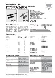
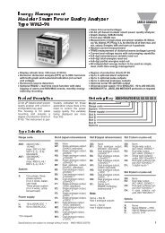
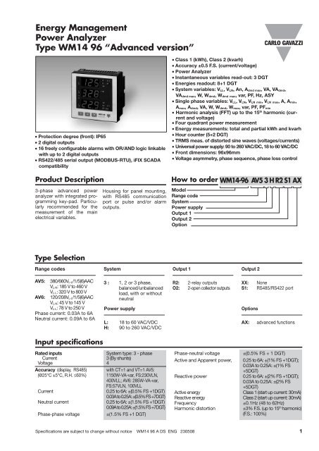
Energy Management<br />
Power Analyzer<br />
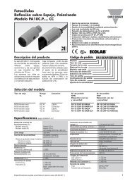
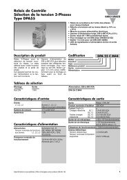
Type <strong>WM14</strong> <strong>96</strong> “<strong>Advanced</strong> version”<br />
• Protection degree (front): IP65<br />
• 2 digital outputs<br />
• 16 freely configurable alarms with OR/AND logic linkable<br />
with up to 2 digital outputs<br />
• RS422/485 serial output (MODBUS-RTU), iFIX SCADA<br />
compatibility<br />
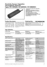
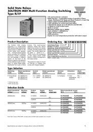
Product Description<br />
3-phase advanced power<br />
analyzer with integrated programming<br />
key-pad. Particularly<br />
recommended for the<br />
measurement of the main<br />
electrical variables.<br />
Type Selection<br />
Range codes<br />
AV5: 380/660VL-L/1/5(6)AAC<br />
VL-N: 185 V to 460 V<br />
VL-L: 320 V to 800 V<br />
AV6: 120/208VL-L/1/5(6)AAC<br />
VL-N: 45 V to 145 V<br />
VL-L: 78 V to 250 V<br />
Phase current: 0.03A to 6A<br />
Neutral current: 0.09A to 6A<br />
Input specifications<br />
Housing for panel mounting,<br />
with RS485 communication<br />
port or pulse and/or alarm<br />
outputs.<br />
System<br />
3 : 1, 2 or 3 phase,<br />
balanced/unbalanced<br />
load, with or without<br />
neutral<br />
Power supply<br />
L: 18 to 60 VAC/VDC<br />
H: 90 to 260 VAC/VDC<br />
Rated inputs System type: 3 - phase<br />
Current 3 (By shunts)<br />
Voltage 4<br />
Accuracy (display, RS485) with CT=1 and VT=1 AV5:<br />
(@25°C ±5°C, R.H. ≤60%) 1150W-VA-var, FS:230VLN,<br />
400VLL; AV6: 285W-VA-var,<br />
FS:57VLN, 100VLL<br />
Current 0.25 to 6A: ±(0.5% FS +1DGT)<br />
0.03A to 0.25A: ±(0.5% FS +7DGT)<br />
Neutral current 0.25 to 6A: ±(1.5% FS +1DGT)<br />
0.09A to 0.25A: ±(1.5% FS +7DGT)<br />
Phase-phase voltage ±(1.5% FS +1 DGT)<br />
• Class 1 (kWh), Class 2 (kvarh)<br />
• Accuracy ±0.5 F.S. (current/voltage)<br />
• Power Analyzer<br />
• Instantaneous variables read-out: 3 DGT<br />
• Energies readout: 8+1 DGT<br />
• System variables: VLL, VLN, An, Admd max, VA, VAdmd,<br />
VAdmd max, W, Wdmd, Wdmd max, var, PF, Hz, ASY<br />
• Single phase variables: VLL, VLN, VLN min, VLN max, A, Amin,<br />
Amax, Admd, VA, W, Wdmd, Wmax, var, PF, PFmin<br />
• Harmonic analysis (FFT) up to the 15 th harmonic (current<br />
and voltage)<br />
• Four quadrant power measurement<br />
• Energy measurements: total and partial kWh and kvarh<br />
• Hour counter (5+2 DGT)<br />
• TRMS meas. of distorted sine waves (voltages/currents)<br />
• Universal power supply: 90 to 260 VAC/DC, 18 to 60 VAC/DC<br />
• Front dimensions: <strong>96</strong>x<strong>96</strong>mm<br />
• Voltage asymmetry, phase sequence, phase loss control<br />
How to order <strong>WM14</strong>-<strong>96</strong> AV5 3 H R2 S1 AX<br />
Model<br />
Range code<br />
System<br />
Power supply<br />
Output 1<br />
Output 2<br />
Option<br />
Output 1<br />
R2: 2-relay outputs<br />
O2: 2-open collector outputs<br />
Output 2<br />
XX: None<br />
S1: RS485/RS422 port<br />
Options<br />
AX: advanced functions<br />
Phase-neutral voltage ±(0.5% FS + 1 DGT)<br />
Active and Apparent power, 0.25 to 6A: ±(1% FS +1DGT);<br />
0.03A to 0.25A: ±(1% FS<br />
+5DGT)<br />
Reactive power 0.25 to 6A: ±(2% FS +1DGT);<br />
0.03A to 0.25A: ±(2% FS<br />
+5DGT)<br />
Active energy Class 1 (start up current: 30mA)<br />
Reactive energy Class 2 (start up current: 30mA)<br />
Frequency ±0.1Hz (48 to 62Hz)<br />
Harmonic distortion ±3% F.S. (up to 15 th harmonic)<br />
(F.S.: 100%)<br />
Specifications are subject to change without notice <strong>WM14</strong> <strong>96</strong> A DS ENG 230508 1
<strong>WM14</strong>-<strong>96</strong><br />
Power Analyzer<br />
<strong>Advanced</strong><br />
Input specifications (cont.)<br />
Additional errors<br />
Humidity ≤0.3% FS, 60% to 90% RH<br />
Temperature drift ≤ 200ppm/°C<br />
Sampling rate 1600 samples/s @ 50Hz<br />
1900 samples/s @ 60Hz<br />
Display refresh time 200ms (FFT off)<br />
500ms (FFT on)<br />
Display<br />
Type LED, 14mm<br />
Read-out for instant. var. 3x3 DGT<br />
Read-out for energies 3+3+3 DGT (Max indication:<br />
999 999 99.9)<br />
Read-out for hour counter 1+3+3 DGT (Max. indication:<br />
9 999 9.99)<br />
Output Specifications<br />
Digital outputs<br />
Pulse type<br />
Number of outputs Up to 2<br />
Type Programmable from 0.01 to 500<br />
pulses per kWh/kvarh<br />
Pulse duration<br />
≥ 100ms < 120msec (ON),<br />
≥ 100ms (OFF)<br />
according to EN62053-31<br />
Alarm type<br />
Number of outputs Up to 2, independent<br />
Alarm modes Up alarm, down alarm, in<br />
window alarm, out window<br />
alarm. Start-up deactivation<br />
function available for<br />
all kinds of alarm. All of<br />
them connectable on all<br />
variables (see the table “List<br />
of the variables that can be<br />
connected to”)<br />
Set-point adjustment From 0 to 100% of the<br />
display scale<br />
Hysteresis From 0 to full scale<br />
On-time delay 0 to 255s<br />
Output status Selectable; normally<br />
de-energized and normally<br />
energized<br />
Min. response time ≤400ms, filters excluded,<br />
With FFT off; ≤1s, with FFT on.<br />
(With Set-point on-time<br />
delay: “0 s”)<br />
Remote control The digital outputs status<br />
can be managed by means<br />
of serial communication<br />
RS485 if programmed as<br />
“rEm”<br />
Note The 2 digital outputs<br />
can also work as pulse<br />
output and alarm<br />
output.<br />
Static outputs<br />
Purpose For pulse outputs or for<br />
alarm outputs<br />
Signal VON 1.2 VDC/ max. 100 mA<br />
Measurements Current, voltage, power,<br />
power factor, frequency<br />
Type TRMS measurement of<br />
distorted waves.<br />
Coupling type Direct<br />
Crest factor < 3, max 10A peak<br />
Input impedance<br />
380/660VL-L (AV5) 1.6 MΩ ±5%<br />
120/208VL-L (AV6) 1.6 MΩ ±5%<br />
Current ≤ 0.02Ω<br />
Frequency 48 to 62 Hz<br />
Overload protection (max values)<br />
Continuous: voltage/current AV5: 460VLN, 800VLL/6A<br />
AV6: 145VLN, 250VLL/6A<br />
For 500ms: voltage/current AV5: 800VLN, 1380VLL/36A<br />
AV6: 240VLN, 416VLL/36A<br />
VOFF 30 VDC max.<br />
Insulation By means of optocuplers,<br />
4000 VRMS output to measuring<br />
inputs,<br />
4000 VRMS output to power<br />
supply input.<br />
Relay outputs<br />
Purpose For alarm outputs or for pulse<br />
outputs<br />
Type Relay, SPST type<br />
AC 1-5A @ 250VAC<br />
DC 12-5A @ 24VDC<br />
AC 15-1.5A @ 250VAC<br />
DC 13-1.5A @ 24VDC<br />
Mecanical life ≥30x10 6 operations<br />
Electrical life ≥10 5 operations<br />
(@ 5A, 250V, PF1)<br />
Insulation 4000 VRMS output to<br />
measuring input,<br />
4000 VRMS output to<br />
supply input.<br />
RS422/RS485 (on request)<br />
Multidrop<br />
bidirectional (static and<br />
dynamic variables)<br />
Connections 2 or 4 wires, max. distance<br />
1000m, termination directly<br />
on the instrument<br />
Addresses From 1 to 255, selectable<br />
Protocol MODBUS/JBUS (RTU)<br />
Data (bidirectional)<br />
Dynamic (reading only) System and phase variables:<br />
see table “List of variables...”<br />
Static (reading and writing) All the configuration parameters.<br />
Data format 1 start bit, 8 data bit,<br />
no parity,1 stop bit<br />
Baud-rate 4800, <strong>96</strong>00,19200, 38400bits/s<br />
Insulation By means of optocouplers,<br />
2.5 K VRMS output to<br />
measuring input<br />
2.5 K VRMS output to<br />
supply input<br />
2 Specifications are subject to change without notice <strong>WM14</strong> <strong>96</strong> A DS ENG 230508
<strong>WM14</strong>-<strong>96</strong><br />
Power Analyzer<br />
<strong>Advanced</strong><br />
Software functions<br />
Password Numeric code of max. 3<br />
digits; 2 protection levels<br />
of the programming data<br />
1st level Password “0”, no<br />
protection<br />
2nd level Password from 1 to 999,<br />
all data are protected<br />
System selection<br />
System 3, unbalanced 3-phase (3-wire, 4-wire)<br />
3-phase ARON<br />
2-phase (3-wire)<br />
System 3, balanced 3-phase (3-wire, 4-wire)<br />
3-phase (4-wire) “1CT+1VT”<br />
3-phase (3-wire) “1CT+2VT”<br />
1-phase (2-wire)<br />
Transformer ratio<br />
CT 1 to 60000<br />
VT/PT 1.0 to 6000.0<br />
Filter<br />
Operating range 0 to 100% of the input<br />
display scale<br />
Filtering coefficient 1 to 32<br />
Filter action Measurements, alarms,<br />
serial output<br />
(fundamental variables: V, A,<br />
W and their derived ones).<br />
Displaying Up to 3 variables per page<br />
See table “Display pages”<br />
Alarms<br />
Working mode “OR” or “AND” or<br />
“OR+AND” functions (see<br />
“Alarm parameter and logic”<br />
page).<br />
Freely programmable on up<br />
to 16 total alarms<br />
(out1+out2). The alarms<br />
can be connected to any<br />
variables available in the<br />
table “List of the variables<br />
that can be connected to”<br />
Reset By means of keypad:<br />
The following kinds of reset<br />
are available:<br />
- all values stored as “dmd<br />
max”:<br />
Admd max, Wdmd max,<br />
VAdmd max<br />
- all values stored as<br />
“max”:<br />
A1, A2, A3, WL1,<br />
WL2, WL3, VL1, VL2, VL3,<br />
and as “Min”:<br />
PF1, PF2, PF3,<br />
A1, A2, A3, VL1, VL2, VL3 .<br />
- Only the kWh and kvarh<br />
partial counters<br />
- Both the kWh and kvarh<br />
total and partial counters<br />
- the hour counter.<br />
Specifications are subject to change without notice <strong>WM14</strong> <strong>96</strong> A DS ENG 230508 3
<strong>WM14</strong>-<strong>96</strong><br />
Power Analyzer<br />
<strong>Advanced</strong><br />
Power Supply Specifications<br />
AC/DC voltage 90 to 260VAC/DC<br />
16 to 60VAC/DC<br />
General Specifications<br />
Operating 0 to +50°C (32 to 122°F)<br />
temperature (RH < 90% non condensing)<br />
Storage -30 to +60°C (-22 to 140°F)<br />
temperature (RH < 90% non condensing)<br />
Overvoltage category Cat. III (IEC 60664, EN60664)<br />
Insulation (for 1 minute) 4kVACRMS<br />
between measuring<br />
inputs and power supply.<br />
4kVAC/DC @ I ≤3mA<br />
between measuring inputs<br />
and RS485.<br />
4kVAC RMS between<br />
power supply and<br />
RS485.<br />
Dielectric strength 4kVACRMS (for 1 min)<br />
EMC<br />
Emissions EN61000-6-3<br />
residential environment,<br />
commerce and light industry<br />
Insulation between inputs and outputs<br />
Measuring<br />
Inputs V<br />
Measuring<br />
Inputs A<br />
Relay<br />
outputs<br />
Power consumption AC: 6 VA<br />
DC: 3.5 W<br />
Immunity EN61000-6-2<br />
industrial environment.<br />
Pulse voltage (1.2/50µs) EN61000-4-5<br />
Safety standards IEC60664, IEC61010-1<br />
EN60664, EN61010-1<br />
Approvals CE<br />
Connections 5(6) A Screw-type<br />
Max cable cross sect. area 2.5 mm 2<br />
Housing<br />
Dimensions (WxHxD) <strong>96</strong> x <strong>96</strong> x 63 mm<br />
Material A<strong>BS</strong><br />
self-extinguishing: UL 94 V-0<br />
Mounting Panel<br />
Protection degree Front: IP65 (standard),<br />
NEMA4x, NEMA12<br />
Connections: IP20<br />
Weight Approx. 400 g (pack. incl.)<br />
Open collector<br />
outputs<br />
Communication<br />
Port<br />
Power Supply<br />
90-260VAC/DC<br />
Power Supply<br />
18-60VAC/DC<br />
Measuring Inputs V - - 4kV 4kV 2.5kV 4kV 4kV<br />
Measuring Inputs A - - 4kV 4kV 2.5kV 4kV 4kV<br />
Relay outputs 4kV 4kV - - 2.5kV 4kV 4kV<br />
Open col. outputs<br />
Communication<br />
Port<br />
4kV 4kV - - 2.5kV 4kV 4kV<br />
2.5kV 2.5kV - - - 4kV 4kV<br />
90-260VAC/DC 4kV 4kV 4kV 4kV 4kV - -<br />
18-60VAC/DC 4kV 4kV 4kV 4kV 4kV - -<br />
NOTE: In case of fault of first insulation the current from the measuring inputs to the ground is lower than 2 mA.<br />
4 Specifications are subject to change without notice <strong>WM14</strong> <strong>96</strong> A DS ENG 230508
<strong>WM14</strong>-<strong>96</strong><br />
Power Analyzer<br />
<strong>Advanced</strong><br />
List of the variables that can be connected to:<br />
• RS485/RS422 communication port<br />
• Alarm outputs (“max / min” variable, “energies” and “hour counter” excluded)<br />
• Pulse outputs (only “energies”)<br />
No Variable 1-phase 2-phase 3-ph. 4-wire 3-ph. 4-wire 3 ph. 3-wire 3 ph. 3-wire Notes<br />
system system balanced sys. unbal. sys. bal. sys. unbal. sys.<br />
1 V L1 x x x x o o # ∆<br />
2 V L2 o x x x o o # ∆<br />
3 V L3 o o x x o o # ∆<br />
4 V L-N sys o x x x o o Sys = system<br />
5 V L1-2 o x x x x x<br />
6 V L2-3 o x x x x x<br />
7 V L3-1 o o x x x x<br />
8 V L-L sys o x x x x x Sys = system<br />
9 A L1 x x x x x x # ∆<br />
10 A L2 o x x x x x # ∆<br />
11 A L3 o o x x x x # ∆<br />
12 An o x x x x x<br />
13 W L1 x x x x o o ◆<br />
14 W L2 o x x x o o ◆<br />
16 W L3 o o x x o o ◆<br />
17 W sys o x x x x x Sys = system<br />
18 var L1 x x x x o o<br />
19 var L2 o x x x o o<br />
20 var L3 o o x x o o<br />
21 var sys o x x x x x Sys = system<br />
22 VA L1 x x x x o o<br />
23 VA L2 o x x x o o<br />
24 VA L3 o o x x o o<br />
25 VA sys o x x x x x Sys = system<br />
26 PF L1 x x x x o o H<br />
27 PF L2 o x x x o o H<br />
28 PF L3 o o x x o o H<br />
29 PF sys o x x x x x Sys = system<br />
30 Hz x x x x x x<br />
31 Phase seq. o o x x x x<br />
32 ASY L-N o x x x x x<br />
33 ASY L-L o x x x x x<br />
34 Phase loss o x x x x x<br />
35 VA sys dmd x x x x x x Sys = system ◆❍<br />
36 W sys dmd x x x x x x Sys = system ◆❍<br />
37 A L1 dmd x x x x x x<br />
38 A L2 dmd o x x x x x<br />
39 A L3 dmd o o x x x x<br />
40 A L dmd x x x x x x ❏ ◆<br />
41 A L1 THD x x x x x x<br />
42 A L2 THD o x x x x x<br />
43 A L3 THD o o x x x x<br />
44 V L1 THD x x x x x x<br />
45 V L2 THD o x x x x x<br />
46 V L3 THD o o x x x x<br />
47 kWh x x x x x x Total and partial<br />
48 kvarh x x x x x x Total and partial<br />
49 hours x x x x x x<br />
(x) = available (o) = not available<br />
(◆) These variables are available also as MAX detection and data storage (on EEPROM at power down).<br />
(H) These variables are available also as MIN detection and data storage (on EEPROM at power down).<br />
(❏) Highest value among the 3-phase.<br />
(❍) Alarm available only on the consumed power (+).<br />
(#) These variables are available also for the MAX values, which have not been stored in the EEPROM at power down.<br />
(∆) These variables are available also for the MIN values, which have not been stored in the EEPROM at power down.<br />
Specifications are subject to change without notice <strong>WM14</strong> <strong>96</strong> A DS ENG 230508 5
<strong>WM14</strong>-<strong>96</strong><br />
Power Analyzer<br />
<strong>Advanced</strong><br />
Alarm parameters and logic<br />
OFF alarm<br />
ON alarm<br />
Up alarm<br />
On alarm > Off alarm<br />
AND/OR logical alarm examples:<br />
A: AND B: AND C: AND<br />
A: AND B: AND C: AND<br />
A: AND B: AND C: AND<br />
- Block enable.<br />
- Controlled variable (VLN, ...).<br />
- Alarm type (up, down, in window,<br />
out window).<br />
- Activation function.<br />
Off alarm<br />
On alarm<br />
Down alarm<br />
On alarm < Off alarm<br />
A: OR<br />
B: OR<br />
C: OR<br />
A: OR<br />
B: OR<br />
C: OR<br />
A: OR<br />
B: OR<br />
C: OR<br />
- ON set-point.<br />
- OFF set-point.<br />
- ON delay.<br />
- Logical function (AND, OR).<br />
- Digital output (1, 2).<br />
Note: any alarm working mode can be linked to the “Start-up deactivation” function which disables only the first alarm after<br />
power on of the instrument.<br />
6 Specifications are subject to change without notice <strong>WM14</strong> <strong>96</strong> A DS ENG 230508<br />
In alarm 1<br />
In alarm 2<br />
In window alarm<br />
AND OR OR+AND<br />
A: OR<br />
B: OR<br />
C: AND D: AND<br />
A: OR<br />
B: OR<br />
C: AND D: AND<br />
A: OR<br />
B: OR<br />
<br />
A, B, C... up to 16<br />
parameter control<br />
blocks.<br />
Out alarm 1<br />
Activation<br />
Out window alarm with<br />
start up deactivation<br />
C: AND D: AND<br />
Out alarm 2
<strong>WM14</strong>-<strong>96</strong><br />
Power Analyzer<br />
<strong>Advanced</strong><br />
Display pages<br />
Display variables in 3-phase systems (in a 3-phase system with neutral)<br />
No 1 st variable 2 nd variable 3 rd variable Note<br />
1 % “ASY” “L N” Phase to neutral asymmetry<br />
2 V L1 V L2 V L3<br />
3 V LN sys PF sys Sys = system<br />
4 V LL sys PF sys Decimal point blinking on the right<br />
of the display<br />
5 V L1 2 V L2 3 V L3 1 Decimal point blinking on the right<br />
of the display<br />
6 % “ASY” “L L” Phase to phase asymmetry<br />
7 “PH” “SEq” 1 2 3 / 1 3 2 Phase sequence<br />
8 A L1 A L2 A L3<br />
9 A dmd L1 A dmd L2 A dmd L3 dmd = demand (integration time<br />
selectable from 1 to 30 minutes)<br />
10 An “n” Hz An= neutral current<br />
11 W L1 W L2 W L3<br />
12 W dmd L1 W dmd L2 W dmd L3 dmd = demand (integration time<br />
selectable from 1 to 30 minutes)<br />
13 PF L1 PF L2 PF L3<br />
14 var L1 var L2 var L3<br />
15 VA L1 VA L2 VA L3<br />
16 VA sys W sys var sys<br />
17 VA dmd sys W dmd sys Hz dmd = demand (integration time<br />
selectable from 1 to 30 minutes)<br />
18 V max L1 V max L2 V max L3 Max value of phase to neutral voltage<br />
19 V min L1 V min L2 V min L3 Min value of phase to neutral voltage<br />
20 A max L1 A max L2 A max L3 Max value of current<br />
21 A min L1 A min L2 A min L3 Min value of current<br />
22 W max L1 W max L2 W max L3 Max value of W<br />
23 PF min L1 PF min L2 PF min L3 Min value of PF<br />
24 VA dmd sys max W dmd sys max “H” Max system dmd<br />
25 A dmd max “H” Highest value among the 3-phase<br />
26 V L1 THD V L2 THD V L3 THD<br />
27 A L1 THD A L2 THD A L3 THD<br />
28 h (MSD) h h (LSD) Hour counter<br />
29 kvarh (MSD) kvarh kvarh (LSD) Partial counter<br />
30 kWh (MSD) kWh kWh (LSD) Partial counter<br />
31 kvarh (MSD) kvarh kvarh (LSD) Total counter<br />
32 kWh (MSD) kWh kWh (LSD) Total counter<br />
MSD: most significant digit<br />
LSD: least significant digit<br />
L<br />
1<br />
L<br />
2<br />
h<br />
L<br />
3<br />
V<br />
A<br />
VA<br />
W<br />
var<br />
Hz<br />
k<br />
M<br />
al<br />
PF dmd<br />
1) Example of kWh visualization:<br />
This example is showing 15 933 453.7 kWh<br />
2) Example of kvarh visualization:<br />
This example is showing 3 553 944.9 kvarh<br />
Specifications are subject to change without notice <strong>WM14</strong> <strong>96</strong> A DS ENG 230508 7<br />
L<br />
1<br />
L<br />
2<br />
h<br />
L<br />
3<br />
V<br />
A<br />
VA<br />
W<br />
var<br />
Hz<br />
k<br />
M<br />
al<br />
PF dmd
<strong>WM14</strong>-<strong>96</strong><br />
Power Analyzer<br />
<strong>Advanced</strong><br />
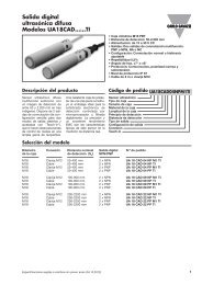
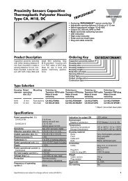
Waveform of the signals that can be measured<br />
Figure A<br />
Sine wave, undistorted<br />
Fundamental content 100%<br />
Harmonic content 0%<br />
Arms = 1.1107 | A |<br />
Accuracy<br />
Wh, accuracy (RDG) depending on the current<br />
+1,5%<br />
+1%<br />
0%<br />
-1%<br />
-1,5%<br />
PF=1<br />
PF=L0.5<br />
or C0.8<br />
Error<br />
0.25A<br />
(0.05Ib)<br />
0.5A<br />
(0.1Ib)<br />
0.5A<br />
(0.1Ib)<br />
1A<br />
(0.2Ib)<br />
5A (Ib)<br />
5A (Ib)<br />
Accuracy limits (Active energy)<br />
5(6A) Start-up current: 30mA<br />
Used calculation formulas<br />
Phase variables<br />
Instantaneous effective voltage<br />
Instantaneous active power<br />
Instantaneous power factor<br />
Instantaneous effective current<br />
Instantaneous apparent power<br />
Instantaneous reactive power<br />
Figure B<br />
Sine wave, indented<br />
Fundamental content 10...100%<br />
Harmonic content 0...90%<br />
Frequency spectrum: 3rd to 16th harmonic<br />
Additional error:
<strong>WM14</strong>-<strong>96</strong><br />
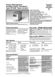
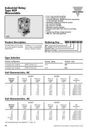
Wiring diagrams<br />
1 3 5 6 7 8 9 1011 12 13 14<br />
15 17 19 21 23 24 25 26 27 28<br />
3-ph, 3-wire, unbalanced load Fig. 3<br />
ARON connection<br />
Power Analyzer<br />
<strong>Advanced</strong><br />
Harmonic Analysis<br />
Analysis principle FFT<br />
Harmonic measurement<br />
Current Up to 15th harmonic<br />
Voltage Up to 15th harmonic<br />
Type of harmonics THD (VL1)<br />
THD (VL2)<br />
THD (VL3)<br />
THD (AL1)<br />
THD (AL2)<br />
THD (AL3)<br />
1-ph, 2-wire Fig. 1<br />
L1<br />
N<br />
17 15 24 23<br />
1-CT connection<br />
ARON and 2-VT/PT connections<br />
Display of harmonic values THD %<br />
Others The harmonic distortion<br />
can be measured in both<br />
3-wire or 4-wire systems.<br />
When the CT is connected to earth, a leakage current from 0 to 1.8mA max is generated, whose value depends on the input<br />
impedance values of the instrument, on the type of connection and on the line voltage measured by the instrument.<br />
F1= 315mA<br />
L1<br />
L2<br />
L3<br />
F1<br />
17 19 21 24 23 28 27<br />
2-ph, 3-wire Fig. 2<br />
2-CT connection<br />
3-ph, 3-wire, unbalanced load Fig. 4 3-ph, 4-wire, unbalanced load Fig. 5<br />
L1<br />
L2<br />
L3<br />
F1<br />
17 19 21 24 23 26 25<br />
3-CT connection<br />
17 19 15 24 23 26 25<br />
NOTE: the current inputs can be connected to the mains ONLY by means of current transformers.<br />
The direct connection is not allowed.<br />
Specifications are subject to change without notice <strong>WM14</strong> <strong>96</strong> A DS ENG 230508 9<br />
L1<br />
L2<br />
N<br />
L1<br />
L2<br />
L3<br />
N<br />
F1<br />
F1<br />
17 19 21 15 24 23 26 25 28 27
<strong>WM14</strong>-<strong>96</strong><br />
Power Analyzer<br />
<strong>Advanced</strong><br />
Wiring diagrams<br />
When the CT is connected to earth, a leakage current from 0 to 1.8mA max is generated, whose value depends on the input<br />
impedance values of the instrument, on the type of connection and on the line voltage measured by the instrument.<br />
1 3 5 6 7 8 9 1011 12 13 14<br />
15 17 19 21 23 24 25 26 27 28<br />
3-ph, 3-wire, unbalanced load Fig. 8<br />
L1<br />
L2<br />
L3<br />
3-CT and 2-VT/PT connections<br />
1-CT connection<br />
17 19 21 24 23 26 25 28 27<br />
3-ph, 4-wire, unbalanced load Fig. 6<br />
L1<br />
L2<br />
L3<br />
N<br />
17 19 21 15 24 23 26 25 28 27<br />
3-CT and 3-VT/PT connections<br />
1-CT connection<br />
3-ph, 3-wire, unbalanced load Fig. 7<br />
3-CT connection<br />
17 19 21 24 23 26 25 28 27<br />
3-ph, 3-wire, balanced load Fig. 9 3-ph, 4-wire balanced load Fig. 10<br />
L1<br />
L2<br />
L3<br />
17 19 21 24 23<br />
1-CT and 1-VT/PT connections<br />
3-ph, 4-wire, balanced load Fig. 11 Fig. 12<br />
L1<br />
L2<br />
L3<br />
N<br />
F1<br />
17 15 24 23<br />
F1<br />
N -<br />
L +<br />
Power supply connection<br />
NOTE: the current inputs can be connected to the mains ONLY by means of current transformers.<br />
The direct connection is not allowed.<br />
10 Specifications are subject to change without notice <strong>WM14</strong> <strong>96</strong> A DS ENG 230508<br />
L1<br />
L2<br />
L3<br />
L1<br />
L2<br />
L3<br />
N<br />
F1<br />
17 15 24 23<br />
01 03<br />
F
<strong>WM14</strong>-<strong>96</strong><br />
Power Analyzer<br />
<strong>Advanced</strong><br />
Output connections<br />
VDC<br />
Fig. 13 Fig. 14<br />
Open collector outputs: The load resistance (Rc) must be<br />
designed so that the closed contact current is lower than<br />
100mA; the VDC voltage must be lower than or equal to 30V.<br />
VDC: external power supply voltage. Out: positive output contact<br />
(open collector transistor). GND: ground output contact<br />
(open collector transistor).<br />
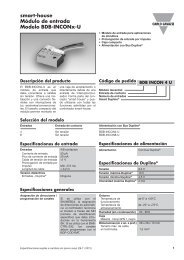
Front Panel Description<br />
L<br />
1<br />
L<br />
2<br />
h<br />
L<br />
3<br />
V<br />
A<br />
VA<br />
W<br />
var<br />
Hz<br />
M<br />
al<br />
PF dmd<br />
<strong>WM14</strong>-<strong>96</strong><br />
S Power Analyzer<br />
dvanced<br />
Dimensions and Panel Cut-out<br />
<strong>96</strong>mm<br />
Out<br />
GND<br />
RC RC<br />
<strong>96</strong>mm<br />
A<br />
VDC<br />
Out<br />
GND<br />
k<br />
RC RC<br />
12 11 13 14 12 11 13 14<br />
OC 2 OC 1 OC 2 OC 1<br />
61.4mm<br />
1<br />
2<br />
<strong>96</strong>mm<br />
15.4mm<br />
Relay out.<br />
11 12 13 14<br />
Fig. 15<br />
Specifications are subject to change without notice <strong>WM14</strong> <strong>96</strong> A DS ENG 230508 11<br />
VDC<br />
Out<br />
GND<br />
2<br />
GND<br />
T<br />
RX+<br />
RX-<br />
TX+<br />
TX-<br />
GND<br />
T<br />
RX+<br />
RX-<br />
TX+<br />
1. Display<br />
LED-type with alphanumeric indications to:<br />
- display configuration parameters;<br />
- display all the measured variables.<br />
TX-<br />
GND<br />
RS485 RS232 PC<br />
2. Key-pad<br />
To program the configuration parameters and the display of<br />
the variables.<br />
S<br />
Key to enter programming and confirm selections;<br />
▲<br />
Keys to:<br />
- programme values;<br />
- select functions;<br />
- display measuring pages.<br />
▲<br />
1<br />
RS485 port<br />
05 06 07 08 09 10<br />
GND T RX+ RX- TX+ TX-<br />
GND<br />
T<br />
RX+<br />
RX-<br />
TX+<br />
TX-<br />
05<br />
06<br />
07<br />
08<br />
09<br />
10<br />
05<br />
06<br />
07<br />
08<br />
09<br />
10<br />
Fig. 17<br />
GND 05<br />
T 06<br />
RX+ 07<br />
RX- 08<br />
TX+ 09<br />
TX- 10<br />
05<br />
06<br />
07<br />
08<br />
09<br />
10<br />
91mm<br />
Fig.16<br />
GND<br />
RS485 RS232 PC<br />
TX+<br />
TX-<br />
RX+<br />
RX-<br />
TX+<br />
TX-<br />
RX+<br />
RX-