NavNet TZtouch Installation Checklist - Furuno USA
NavNet TZtouch Installation Checklist - Furuno USA
NavNet TZtouch Installation Checklist - Furuno USA

You also want an ePaper? Increase the reach of your titles
YUMPU automatically turns print PDFs into web optimized ePapers that Google loves.
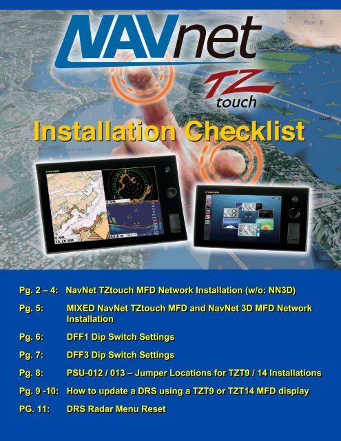
Pg. 2 – 4: <strong>NavNet</strong> <strong>TZtouch</strong> MFD Network <strong>Installation</strong> (w/o: NN3D)<br />
Pg. 5: MIXED <strong>NavNet</strong> <strong>TZtouch</strong> MFD and <strong>NavNet</strong> 3D MFD Network<br />
<strong>Installation</strong><br />
Pg. 6: DFF1 Dip Switch Settings<br />
Pg. 7: DFF3 Dip Switch Settings<br />
Pg. 8: PSU-012 / 013 – Jumper Locations for TZT9 / 14 <strong>Installation</strong>s<br />
Pg. 9 -10: How to update a DRS using a TZT9 or TZT14 MFD display<br />
PG. 11: DRS Radar Menu Reset<br />
Rev: 6
<strong>TZtouch</strong> MFD Network <strong>Installation</strong> (without NN3D):<br />
(2)<br />
FURUNO U.S.A., INC.<br />
Camas, WA<br />
(360) 834-9300<br />
<strong>NavNet</strong> <strong>TZtouch</strong> <strong>Installation</strong> <strong>Checklist</strong><br />
Denton, MD<br />
(410) 479-4420<br />
Connect all <strong>TZtouch</strong> MFDs to the Ethernet Network. If a HUB101 is used, set<br />
the internal HUB DIP switches to OFF (HUB101 DIP Switches are OFF by<br />
Default). <strong>TZtouch</strong> MFDs do not use “power-on” synchronization.<br />
Note: If you use the internal HUB of the TZT14, realize that the HUB will only be able<br />
to relay Ethernet traffic when the MFD is turned ON. For multi-station network<br />
installations, we recommend using an external HUB (such as the <strong>Furuno</strong> HUB101)<br />
allowing redundancy in case an MFD is powered OFF.<br />
Connect all <strong>TZtouch</strong> MFDs to a proper NMEA2000 backbone using drop<br />
cables (18 feet or less).<br />
Note: <strong>TZtouch</strong> MFDs are fully NMEA2000 Certified and do not have an internal<br />
terminal resistor that can be switched ON or OFF. All connections to the NMEA2000<br />
backbone must be “drop” connections (18 feet or less).<br />
Make sure the DFF1 and DFF3 are set up for “fixed IP addresses” (See<br />
appendix for more information on setting up both)<br />
Connect the Radar Ethernet and Power cable to the PSU, then connect the<br />
second Ethernet port of the PSU to the HUB or directly to the <strong>TZtouch</strong> MFD.<br />
Make sure that a jumper is inserted inside the PSU on “J7”. (This allows the<br />
PSU to start without a power synchronization signal).<br />
Note: A sticker “Optional jumper for <strong>TZtouch</strong> included” is placed on all PSU units that<br />
include a jumper for “J7” in the packaging! You MUST still open the PSU and insert it.<br />
If you are utilizing an existing PSU, just order the jumper (part # 001-183-760-00) and<br />
insert it on J7 to make the PSU compatible with a <strong>TZtouch</strong> network.<br />
Power ON the HUB, the PSU, the NMEA2000 backbone and all the sensors,<br />
then start the <strong>TZtouch</strong> MFDs.<br />
Note: During the power ON sequence, the <strong>TZtouch</strong> MFDs display a black screen for 10-<br />
15 seconds: this is normal.
<strong>TZtouch</strong> MFD Network <strong>Installation</strong> (without NN3D):<br />
(3)<br />
FURUNO U.S.A., INC.<br />
Camas, WA<br />
(360) 834-9300<br />
<strong>NavNet</strong> <strong>TZtouch</strong> <strong>Installation</strong> <strong>Checklist</strong><br />
Denton, MD<br />
(410) 479-4420<br />
Once the <strong>TZtouch</strong> MFDs have started, press the “Home” button and touch<br />
“Menu” on each MFD to confirm that you see both a Radar and Sounder menu<br />
(assuming you have both a Sounder and a Radar connected to the Ethernet<br />
Network).<br />
If you are missing the Sounder menu, make sure that the DFF1/DFF3 sounder DIP<br />
switch settings are correct and that you see good traffic (blinking green light) on the<br />
Ethernet port.<br />
If you are missing the Radar menu, make sure the PSU is ON (Green LED). If the<br />
PSU is OFF, make sure jumper “J7” is inserted. If the PSU is ON but you cannot<br />
see the Radar menu, you will have to upgrade the Radar software to v1.16.<br />
If the Radar screen shows “Power OFF” you may need to reset the DRS (follow the<br />
“<strong>TZtouch</strong> DRS Update” paragraph found on page 11 in the appendix.<br />
Note: All DRS Radar sensors shipped after 5/1/2012 are “<strong>TZtouch</strong> ready” (loaded<br />
with v1.16 software). If you have a DRS with older software, please follow the<br />
“<strong>TZtouch</strong> DRS Update” document found in the appendix.<br />
Note: There is no need to restart the <strong>TZtouch</strong> MFDs to have the Sounder and Radar<br />
appear in the menu. As soon as the Radar or Sounder are detected on the network,<br />
they will automatically update and appear in real time.<br />
Select the Radar menu and the Radar Source. Scroll down to the “Radar Initial<br />
Setup” to adjust, at minimum, the follown parameters:<br />
Heading Alignment<br />
Antenna Height<br />
Radar Optimization<br />
Note: The radar must be transmitting to press the “Radar Optimization” button.<br />
Repeat if multiple DRS antennas are installed on any network by changing the<br />
“Radar Source” at the beginning of the Radar menu.
<strong>TZtouch</strong> MFD Network <strong>Installation</strong> (without NN3D):<br />
(4)<br />
FURUNO U.S.A., INC.<br />
Camas, WA<br />
(360) 834-9300<br />
<strong>NavNet</strong> <strong>TZtouch</strong> <strong>Installation</strong> <strong>Checklist</strong><br />
Pick one <strong>TZtouch</strong> MFD as the Chart Master and select “ON” in the “Chart<br />
Master Device” setting from the “Initial Setup” menu.<br />
Proceed to the Unit adjustments from the “Units” menu.<br />
Denton, MD<br />
(410) 479-4420<br />
IMPORTANT: All <strong>NavNet</strong> <strong>TZtouch</strong> installations are REQUIRED TO HAVE<br />
AN APPROPRIATE HEADING SENSOR CONNECTED TO THE SYSTEM.<br />
Select the Sounder menu and choose the Sounder Source. Scroll down to the<br />
“Sounder Initial Setup” to adjust at a minimum, the following parameters:<br />
Draft<br />
Transducer<br />
Select the preferred data/sensor sources for the network by pressing the “Data<br />
Source” button in the “Initial Setup” menu.<br />
Select the NMEA2000 PGNs that you want to output on the NMEA2000<br />
backbone from the “PGN Output” button of the “Initial Setup” menu.<br />
Note: The PGN output configuration is a global setting to the system (the PGN<br />
output settings are shared among all the <strong>TZtouch</strong> MFDs).<br />
However, only one MFD will actually output data on the NMEA2000 bus (the one<br />
that was first powered ON). If that MFD is turned OFF, another <strong>TZtouch</strong> MFD will<br />
automatically replace it and start outputting the same PGNs onto the NMEA2000<br />
backbone.<br />
Proceed to the Time Offset adjustments using the “Time Zone” drop down of<br />
the “General” menu.<br />
If a Sirius Satellite Weather Receiver is installed in the network (BBWX1 or<br />
BBWX2), set the “Weather Data Server” to “Sirius” from the “Weather” menu.
Mixed <strong>TZtouch</strong> MFD & NN3D MFD Network <strong>Installation</strong>s:<br />
(5)<br />
FURUNO U.S.A., INC.<br />
Camas, WA<br />
(360) 834-9300<br />
<strong>NavNet</strong> <strong>TZtouch</strong> <strong>Installation</strong> <strong>Checklist</strong><br />
Denton, MD<br />
(410) 479-4420<br />
Make sure the NN3D network is fully operational. (We strongly recommend<br />
that you update any existing NN3D MFDs with the latest software before<br />
integrating a new <strong>TZtouch</strong> MFD into a NN3D Network).<br />
Connect the <strong>TZtouch</strong> to the NN3D Ethernet network.<br />
Note: Leave the HUB101 Dip Switch setting to OFF on the port(s) used to connect<br />
<strong>TZtouch</strong> MFDs.<br />
IMPORTANT: Do NOT connect any <strong>TZtouch</strong> MFDs to the NMEA2000<br />
backbone! Only the NN3D MFDs are connected to the NMEA2000<br />
backbone(s) in a mixed network!<br />
IMPORTANT: All <strong>NavNet</strong> <strong>TZtouch</strong> installations are REQUIRED TO HAVE<br />
AN APPROPRIATE HEADING SENSOR CONNECTED TO THE SYSTEM.<br />
If charts were purchased for the NN3D network, set one <strong>TZtouch</strong> MFD as Chart<br />
Master (from the “Initial Setup” menu), then communicate with <strong>NavNet</strong>3D<br />
SystemID (SI…..) and <strong>TZtouch</strong> SystemID (N4…) to <strong>Furuno</strong> <strong>USA</strong>. <strong>Furuno</strong><br />
<strong>USA</strong> will link the NN3D and <strong>TZtouch</strong> SystemIDs in our www servers. This<br />
will generate new unlock codes for the <strong>TZtouch</strong> MFDs from the existing NN3D<br />
unlock codes. This is a free service provided by <strong>Furuno</strong> <strong>USA</strong>.<br />
Proceed to the Unit adjustments from the “Units” menu.<br />
Proceed to the Time Offset adjustments using the “Time Offset” drop down of<br />
the “General” menu.<br />
If a Sirius Satellite Weather Receiver is installed in the Network (BBWX1 or<br />
BBWX2), set the “Weather Data Server” to “Sirius” from the “Weather” menu.
DFF1 MODE Switch settings<br />
FURUNO U.S.A., INC.<br />
For connection to <strong>NavNet</strong> 1, VX2, NN3D & <strong>TZtouch</strong><br />
The DFF1 comes defaulted to work with the <strong>NavNet</strong> 3D MFDs. If you are<br />
connecting the DFF1 to an original <strong>NavNet</strong>, <strong>NavNet</strong> VX2 or <strong>TZtouch</strong> only<br />
system, you need to change the MODE switches as shown below.<br />
If the DFF1 will be installed in a system comprised of a <strong>NavNet</strong> 3D MFD8,<br />
MFD12 or MFDBB AND either of the <strong>TZtouch</strong> displays, the DIP Switches must<br />
remain in the DEFAULT (<strong>NavNet</strong> 3D) position shown below.<br />
Please confirm the dip switch selection for your type of <strong>NavNet</strong> display. To access the dip<br />
switches, remove the rubber cap on the front of the DFF1 unit.<br />
DEFAULT settings<br />
(<strong>NavNet</strong> 3D)<br />
DEFAULT settings:<br />
ALTERNATE settings:<br />
Camas, WA<br />
(360) 834-9300<br />
Denton, MD<br />
(410) 479-4420<br />
ALTERNATE settings<br />
(<strong>NavNet</strong> 1, VX2 & <strong>TZtouch</strong>)<br />
This setting is used when connecting the DFF1 directly to a NN3D MFD or to a<br />
NN3D network using the HUB101.<br />
This setting is used when connecting the DFF1 to the <strong>NavNet</strong> 1, <strong>NavNet</strong> VX2<br />
and <strong>TZtouch</strong>. This setting must also be used when connecting to a NN3D<br />
network using an Ethernet Hub or Switch, other than the HUB101.<br />
If you have more than one network sounder in the system, please contact <strong>Furuno</strong><br />
Tech Support for setup information.<br />
(6)
For connection to <strong>NavNet</strong> 1, VX2, NN3D & <strong>TZtouch</strong><br />
The DFF3 comes defaulted to work with the <strong>NavNet</strong> 3D MFDs. If you are<br />
connecting the DFF3 to an original <strong>NavNet</strong>, <strong>NavNet</strong> VX2 or <strong>TZtouch</strong> only<br />
system, you need to change the MODE switches as shown below.<br />
If the DFF3 will be installed in a mixed system comprised of a <strong>NavNet</strong> 3D<br />
(MFD8, MFD12 or MFDBB) AND <strong>TZtouch</strong>, the DIP Switches must remain in<br />
the DEFAULT (<strong>NavNet</strong> 3D) position shown below.<br />
DEFAULT settings<br />
(<strong>NavNet</strong> 3D)<br />
DFF3 MODE Switch settings<br />
Only change Dip<br />
Switch settings in<br />
S2. Do not<br />
change settings<br />
for S3.<br />
FURUNO U.S.A., INC.<br />
Camas, WA<br />
(360) 834-9300<br />
Denton, MD<br />
(410) 479-4420<br />
ALTERNATE settings<br />
(<strong>NavNet</strong> 1, VX2 & <strong>TZtouch</strong>)<br />
If you have more than one network sounder in the system, please contact <strong>Furuno</strong><br />
Tech Support for setup information.<br />
(7)
PSU-012 / 013<br />
When the power supply unit PSU-012 / 013 is connected to the TZT 9 / 14, attach<br />
the shorting jumper (supplied) to J7 on the PWR Board.<br />
(PSU-012 = 03P9481) (PSU-013: 03P9483)<br />
(8)<br />
FURUNO U.S.A., INC.<br />
Camas, WA<br />
(360) 834-9300<br />
Jumper location for TZT 9 / 14 <strong>Installation</strong>s<br />
Denton, MD<br />
(410) 479-4420
1. Create the Program Update SD-Card<br />
A blank 128MB or larger SD Card is needed for the update. <strong>Furuno</strong> highly<br />
recommends using “SanDisk” SD Cards.<br />
a) Download the Zip File located under any DRS radar sensor software tab.<br />
b) Unzip the files on your computer. Open the folder you just unzipped. You will see<br />
a folder named “UPLOADER”.<br />
c) Insert an SD Card into your computer. If the SD Card folder automatically opens,<br />
close it. Click START and select “My Computer”.<br />
d) Select the folder you unzipped in step b) and then copy it by pressing (CTRL -C).<br />
e) Open the SD Card and paste the “UPLOADER” folder to the root of the SD Card by<br />
pressing (CTRL-V).<br />
2. Update Procedure<br />
a) Turn ON the MFD and make sure that power is applied to the radar PSU.<br />
b) Insert the SD Card into the right slot card reader of the MFD.<br />
c) Press the (HOME) button. Now press “Menu” and then turn the RotoKey clockwise<br />
to the select the “Initial Setup” menu.<br />
d) Scroll down to the bottom of the “Initial Setup” page using your finger and click on<br />
the “Launch” button in front of “Update Network Equipment”.<br />
e) The screen of the MFD will turn black and display “Initialize”.<br />
(9)<br />
FURUNO U.S.A., INC.<br />
Camas, WA<br />
(360) 834-9300<br />
How to Update a DRS radar sensor using a<br />
TZT9 or TZT14 MFD display<br />
Denton, MD<br />
(410) 479-4420<br />
(Continued on next page)
2. Update Procedure (continued)<br />
f) If you don’t see the DRS listed after the initialization, proceed to the following<br />
steps:<br />
a. Power the DRS OFF and then back ON. This can be done by cutting the<br />
power to the PSU or by disconnecting and then reconnecting the power cable<br />
to the DRS.<br />
b. Wait for 2 minutes.<br />
c. Click “Scan” on the MFD to refresh the list.<br />
g) Click on “START” to begin to update the DRS.<br />
h) At the end of the process, click on “OK” when the message “Ready to shut down to<br />
complete update” appears.<br />
(10)<br />
FURUNO U.S.A., INC.<br />
Camas, WA<br />
(360) 834-9300<br />
Denton, MD<br />
(410) 479-4420
DRS Radar Menu Reset<br />
After updating the software in an existing DRS Radar Sensor to version 1.16 or installing a<br />
new DRS Radar Sensor, the Radar Menu in the <strong>TZtouch</strong> MFD must be reset to default<br />
settings.<br />
Before you begin, confirm that the DRS Radar sensor and the <strong>TZtouch</strong> MFD display are<br />
properly connected, the <strong>TZtouch</strong> MFD display is powered on and there is a Radar selection<br />
option showing on the Home screen.<br />
Now you are ready to follow the steps below to reset the <strong>TZtouch</strong> Radar Menu to default<br />
settings.<br />
1. Press the (Home) key and then press the “Menu” soft key.<br />
2. Turn the (Rotokey) clockwise to “Initial Setup”.<br />
3. Scroll down to view the selections for “Data Acquisition” and press the “Select”<br />
soft key next to “Sensor List”.<br />
4. Confirm that the radar antenna is listed and that the software version is current.<br />
16:03:03:02.<br />
5. Press the “Close” soft key to return to the “Initial Setup” menu.<br />
6. Turn the (Rotokey) counter-clockwise to “Radar”.<br />
7. Scroll down to “Reset Default Settings” at the bottom of the “Radar” menu.<br />
8. Press the “Reset” soft key and then select “Yes” when asked, “Are you sure you<br />
want to reset to default settings?”<br />
9. Scroll up to “Radar Source” at the top of the menu.<br />
FURUNO U.S.A., INC.<br />
Camas, WA<br />
(360) 834-9300<br />
Denton, MD<br />
(410) 479-4420<br />
10. Press the radar model that is listed for “Radar Source” to reselect it and then click<br />
the “Close” soft key.<br />
11. If ST-BY, ON TIME and TX TIME appear at the center of the Radar screen,<br />
press the (Rotokey) and then select “TX Radar” from the (Rotokey) menu.<br />
Note: It may take a few extra seconds for the radar antenna to begin rotating the first time,<br />
but after that, the radar will begin rotating as soon as you press “TX Radar”.<br />
(11)