
Create successful ePaper yourself
Turn your PDF publications into a flip-book with our unique Google optimized e-Paper software.
<strong>F+</strong><br />
Manual Chucks
110.10.07 E 01/09<br />
2<br />
This catalogue describes the key components<br />
of a power chucking system featuring the<br />
following FORKARDT <strong>manual</strong> chuck:<br />
<strong>F+</strong><br />
Should you require further information<br />
beyond the data contained in this catalogue,<br />
please contact FORKARDT.<br />
The colleagues of our sales department will be<br />
pleased to help you.<br />
For more information visit our website at:<br />
www.forkardt.com<br />
As we are constantly striving to improve our products,<br />
the dimensions and specifications in this catalogue<br />
cannot always represent the latest state of the art;<br />
they are therefore given as an indication only and are<br />
not binding.<br />
Contents<br />
FORKARDT Seite<br />
<strong>F+</strong> <strong>manual</strong> <strong>chucks</strong><br />
Technical features<br />
Advantages at a glance 3<br />
Chuck dimensions with cylindrical<br />
spigot mounting recess 4<br />
Dimensions and Performance data 5<br />
Mounting and adaptor flange<br />
for short taper mounting 6<br />
Calculations 7<br />
Jaws 8 - 9<br />
Further <strong>manual</strong> <strong>chucks</strong> 10<br />
Some other FORKARDT products 11<br />
W O R K H O L D I N G S O L U T I O N S W O R L D W I D E
<strong>F+</strong> <strong>manual</strong> wedge block chuck<br />
with open centre<br />
The wedge block principle, invented by FORKARDT,<br />
has for decades formed the basis of diverse workholding<br />
systems, all of which are indispensable in<br />
modern production technology today.<br />
Over several generations, experts at FORKARDT<br />
have made ongoing improvements to the wedge<br />
block chuck and adapted it to advances in the machine<br />
tool construction sector.<br />
The latest addition to the successful family of<br />
FORKARDT hand–operated <strong>chucks</strong> is the <strong>F+</strong>:<br />
A new chuck with a long tradition, it combines all the<br />
advantages of the thoroughly tried and tested F chuck,<br />
and enhances them with new materials and modern<br />
production engineering expertise.<br />
Technical features:<br />
• Hardened steel chuck body for high precision<br />
and long life performance.<br />
• Internal components made of high-quality steels<br />
for maximum gripping force.<br />
• Large through bore hole for bar work.<br />
• <strong>F+</strong> <strong>manual</strong> <strong>chucks</strong> are compatible with virtually<br />
all lathes.<br />
For non-standard<br />
spindle noses, special<br />
mounting parts are<br />
available on request.<br />
• Tried and tested F jaw<br />
system in an unchanged<br />
design.<br />
• Jaw types for diverse<br />
applications.<br />
• Maximum repeat<br />
accuracy when reusing<br />
jaws.<br />
• Easy use of existing sets<br />
of jaws.<br />
• Wedge blocks moving<br />
transversely to the jaws allowing, after a short link<br />
out stroke, the jaws to be relocated, turned or<br />
changed.<br />
• Maximum operating speeds due<br />
to low jaw weight.<br />
• Single jaw locking device for safe handling.<br />
• The gripping force is transmitted over generously<br />
dimensioned surfaces (no point or linear contact).<br />
Advantages at a glance:<br />
• Backlash-free mechanism for maximum accuracy.<br />
• Maximum loadability and wear resistance.<br />
• Quick jaw change within seconds.<br />
• Suitable for use on all types of lathes.<br />
• Long service life.<br />
W O R K H O L D I N G S O L U T I O N S W O R L D W I D E<br />
110.10.07 E 01/09<br />
3
110.10.07 E 01/09<br />
4<br />
<strong>F+</strong> <strong>manual</strong> <strong>chucks</strong><br />
Base jaw <strong>F+</strong> 125<br />
Chuck dimensions with cylindrical spigot mounting recess<br />
Chuck type <strong>F+</strong> 125 160 200 250 315 400 500 630<br />
Chuck size A mm 125 161 206 255 318 400 500 630<br />
Bore B +0,1<br />
mm 35 45 55 75 100 130 180 270<br />
Centering - Ø C H6<br />
mm 115 145 185 235 300 380 460 580<br />
Jaw connection F125 F160 F200 F250 F315 F400 F400 F630<br />
Base jaw length D mm 47 74 90 110 125 160 160 230<br />
Height of centering F mm 4 5 5 6 6 6 6 6<br />
Mounting bolts G mm 3xM8 3xM10 3xM12 3xM16 3xM20 3xM24 3xM24 3xM24<br />
Eyebolt thread G1 mm - - - - M16 M16 M16 M20<br />
Chuck height H mm 46.5 63 81.3 92 111 118 119 143<br />
Clearance H1 mm - - - - 55 55 55 70<br />
Clearance H2 mm 53.1 69 88 99 119 129 130 155<br />
Thread length J mm 11 13 18 27 33 34 34 34<br />
Thread depth J1 mm - - - - 30 30 30 35<br />
Centre distance of chuck key K mm 33 43 54 67 86 111 153.5 196<br />
Hole circle - Ø L mm 100 125 160 200 250 315 235*/400 330.2*/520<br />
Lever length M mm 150 200 280 450 500 600 600 710<br />
Jaw stroke N mm 4.8 6.3 6.8 7.5 9.6 12 12 14.1<br />
Clearance O mm 22.5 31.5 43 47 59 57.5 58.5 72<br />
Distance of lever P mm 115 180 210 300 310 360 520 570<br />
Position of base jaw R min mm 9.2 12.1 13.2 14.8 18.7 24.7 41.6 33.4<br />
R max mm 23.6 31.5 42.6 51 68 93.1 135.7 169.8<br />
Dimension S mm - 2.5 3 3 3 4 4 4<br />
Width across flats SW mm 8 10 12 14 16 19 19 24<br />
Serration pitch T mm 3.6 4.8 4.8 6 7 8.5 8.5 8.5<br />
Angle a° 6°36' 6°36' 3° 4°30' 4°30' 4°30' 4°30' 4°30'<br />
Angle ß° 21°36' 21°36' 18° 19°30' 16°30' 19°30' 14°30' 69°30'<br />
Sloth width a mm 5 18 20 20 26 30 30 40<br />
Sloth depth b mm 3 5 6 6 8 9 9 9<br />
Dimension c1 mm 21 19 23 26 30 35 35 52<br />
Dimension c2 mm 7.5 7 10 10 14 15 15 21<br />
Hole spacing d mm 20 32 40 40 54 60 60 82<br />
Length e mm 47 56 67 73 86 103 103 145<br />
Thread g mm M6 M8x1 M8x1 M12x1.5 M12x1.5 M16x1.5 M16x1.5 M20<br />
Jaw width h mm 14 20 22 26 32 45 45 65<br />
Thread depth j mm 10 16 20 23 25 30 30 32<br />
Tongue k mm 14 8 10 12 12 18 18 24<br />
Chuck constant C1 daN mm/Nm 6,500 11,100 13,100 31,100 39,100 44,200 44,200 56,200<br />
* Hole circle to ASA B 5.9<br />
C2 mm 165 260 320 390 440 570 570 820<br />
W O R K H O L D I N G S O L U T I O N S W O R L D W I D E
Dimensions and Performance data<br />
Max. gripping force<br />
Fspo at maximum<br />
actuating torque<br />
Md max<br />
(maximum actuating<br />
force)<br />
Weight<br />
(with jaws)<br />
Maximum speed n max<br />
Mass moment<br />
of inertia<br />
Outside diameter<br />
Bore<br />
Spindle connection<br />
Chuck-type daN Nm 1/min kg kgm 2 mm mm Ident-No Ident-No Ident-No mm mm mm<br />
Z D164662Z00B - D164662Z00D<br />
J3 D164662J03B - D164662J03D<br />
<strong>F+</strong> 125 3,700 40 6,000 3.7 0.0075 125 35 J4 D164662J04B - D164662J04D 14 46.5 8<br />
J5 D164662J05B - D164662J05D<br />
D3 D164662D03B - D164662D03D<br />
D4 D164662D04B - D164662D04D<br />
Z D164663Z00B D164663Z00E D164663Z00D<br />
J4 D164663J04B D164663J04E D164663J04D<br />
J5 D164663J05B D164663J05E D164663J05D<br />
J6 D164663J06B D164663J06E D164663J06D<br />
<strong>F+</strong> 160 8,000 80 5,200 8.6 0.0325 161 45 D3 D164663D03B D164663D03E D164663D03D 20 63 10<br />
D4 D164663D04B D164663D04E D164663D04D<br />
D5 D164663D05B D164663D05E D164663D05D<br />
D6 D164663D06B D164663D06E D164663D06D<br />
D8 D164663D08B D164663D08E D164663D08D<br />
Z D164664Z00B D164664Z00E D164664Z00D<br />
J4 D164664J04B D164664J04E D164664J04D<br />
J5 D164664J05B D164664J05E D164664J05D<br />
J6 D164664J06B D164664J06E D164664J06D<br />
<strong>F+</strong> 200 12,000 120 4,600 18.5 0.1025 206 55 J8 D164664J08B D164664J08E D164664J08D 22 81.3 12<br />
D4 D164664D04B D164664D04E D164664D04D<br />
D5 D164664D05B D164664D05E D164664D05D<br />
D6 D164664D06B D164664D06E D164664D06D<br />
D8 D164664D08B D164664D08E D164664D08D<br />
Z D164665Z00B D164665Z00E D164665Z00D<br />
J4 D164665J04B D164665J04E D164665J04D<br />
J5 D164665J05B D164665J05E D164665J05D<br />
J6 D164665J06B D164665J06E D164665J06D<br />
J8 D164665J08B D164665J08E D164665J08D<br />
<strong>F+</strong> 250 17,500 190 4,000 32.5 0.285 255 75 J11 D164665J11B D164665J11E D164665J11D 26 92 14<br />
D4 D164665D04B D164665D04E D164665D04D<br />
D5 D164665D05B D164665D05E D164665D05D<br />
D6 D164665D06B D164665D06E D164665D06D<br />
D8 D164665D08B D164665D08E D164665D08D<br />
Z D164666Z00B D164666Z00E D164666Z00D<br />
J6 D164666J06B D164666J06E D164666J06D<br />
J8 D164666J08B D164666J08E D164666J08D<br />
<strong>F+</strong> 315 21,500 210 3,200 62 0.8125 318 100 J11 D164666J11B D164666J11E D164666J11D 32 111 16<br />
D6 D164666D06B D164666D06E D164666D06D<br />
D8 D164666D08B D164666D08E D164666D08D<br />
D11 D164666D11B D164666D11E D164666D11D<br />
Z D164667Z00B D164667Z00E D164667Z00D<br />
J6 D164667J06B D164667J06E D164667J06D<br />
J8 D164667J08B D164667J08E D164667J08D<br />
J11 D164667J11B D164667J11E D164667J11D<br />
<strong>F+</strong> 400 23,400 260 2,200 102 2.2 400 130 J15 D164667J15B D164667J15E D164667J15D 45 118 19<br />
D6 D164667D06B D164667D06E D164667D06D<br />
D8 D164667D08B D164667D08E D164667D08D<br />
D11 D164667D11B D164667D11E D164667D11D<br />
D15 D164667D15B D164667D15E D164667D15D<br />
Z D164668Z00B D164668Z00E D164668Z00D<br />
J8 D164668J08B D164668J08E D164668J08D<br />
J11 D164668J11B D164668J11E D164668J11D<br />
<strong>F+</strong> 500 23,400 260 1,500 159 5.5 500 180 J15 D164668J15B D164668J15E D164668J15D 45 119 19<br />
D8 D164668D08B D164668D08E D164668D08D<br />
D11 D164668D11B D164668D11E D164668D11D<br />
D15 D164668D15B D164668D15E D164668D15D<br />
Z - D164669Z00E D164669Z00D<br />
J11 - D164669J11E D164669J11D<br />
<strong>F+</strong> 630 28,000 315 1,000 293 17.5 630 270 J15 - D164669J15E D164669J15D 65 143 24<br />
D11 - D164669D11E D164669D11D<br />
D15 - D164669D15E D164669D15D<br />
W O R K H O L D I N G S O L U T I O N S W O R L D W I D E<br />
Chuck with<br />
undivided<br />
stepped jaws<br />
Chuck with<br />
base and hard<br />
false jaws<br />
Chuck with<br />
base jaws<br />
Jaw width<br />
Chuck height<br />
Spindle square drive<br />
110.10.07 E 01/09<br />
5
110.10.07 E 01/09<br />
6<br />
<strong>F+</strong> <strong>manual</strong> chuck with integral adaptor and mounting flange<br />
for short taper mounting<br />
Chuck with integral mounting flange for bayonet-type fastening<br />
according to DIN 55027, ISO 702/III, ASA B 5.9 B<br />
Spindle nose<br />
size<br />
Chuck<br />
size<br />
125 160 200 250 315 400 500L 630<br />
3<br />
Type<br />
C1<br />
F125-J3<br />
59.5<br />
4<br />
Type<br />
C1<br />
F125-J4<br />
59.5<br />
F160-J4<br />
75.3<br />
F200-J4<br />
93.3<br />
5<br />
Type<br />
C1<br />
F125-J5<br />
66.5<br />
F160-J5<br />
79.3<br />
F200-J5<br />
95.3<br />
F250-J5<br />
107<br />
6<br />
Type<br />
C1<br />
F160-J6<br />
85.3<br />
F200-J6<br />
97.3<br />
F250-J6<br />
108<br />
F315-J6<br />
128<br />
8<br />
Type<br />
C1<br />
F200-J8<br />
108.3<br />
F250-J8<br />
110<br />
F315-J8<br />
130<br />
F400-J8<br />
138<br />
F500L-J8<br />
138<br />
11<br />
Type<br />
C1<br />
F315-J11<br />
133<br />
F400-J11<br />
138<br />
F500L-J11<br />
138<br />
F630-J11<br />
165<br />
15<br />
Type<br />
C1<br />
F500L-J15<br />
145<br />
F630-J15<br />
167<br />
Chuck with integral mounting flange for camlock fastening<br />
according to DIN 55029, ISO 702/II, ASA B 5.9 D1<br />
Spindle nose<br />
size<br />
Chuck<br />
size<br />
125 160 200 250 315 400 500L 630<br />
3<br />
Type<br />
C1<br />
F125-D3<br />
66.5<br />
4<br />
Type<br />
C1<br />
F125-D4<br />
67.5<br />
F160-D4<br />
85.3<br />
F200-D4<br />
99.3<br />
5<br />
Type<br />
C1<br />
F160-D5<br />
87.3<br />
F200-D5<br />
101.3<br />
F250-D5<br />
112<br />
6<br />
Type<br />
C1<br />
F160-D6<br />
103.3<br />
F200-D6<br />
106.3<br />
F250-D6<br />
117<br />
F315-D6<br />
146<br />
8<br />
Type<br />
C1<br />
F250-D8<br />
122<br />
F315-D8<br />
138<br />
F400-D8<br />
143<br />
F500L-D8<br />
143<br />
11<br />
Type<br />
C1<br />
F315-D11<br />
143<br />
F400-D11<br />
148<br />
F500L-D11<br />
148<br />
F630-D11<br />
170<br />
15<br />
Type<br />
C1<br />
F500L-D15<br />
153<br />
F630-D15<br />
175<br />
Chuck with cylindrical spigot mounting recess, with adaptor flange for mounting on spindle nose<br />
according to DIN 55026, ISO 702/I, ASA B 5.9 A1 and A2<br />
Spindle nose<br />
size<br />
Chuck<br />
size<br />
125 160 200 250 315 400 500L 630<br />
Type F125-A3<br />
3<br />
C1 64.5<br />
Ident. No D1076104000<br />
Type F125-A4 F160-A4 F200-A4<br />
4<br />
C1 64.5 81.3 110<br />
Ident. No D1070764001 D1070418002 -<br />
Type F160-A5 F200-A5 F250-A5<br />
5<br />
C1 81.3 110 110<br />
Ident. No D1070419002 D1070417002 D1070352002<br />
Type F200-A6 F250-A6 F315-A6<br />
6<br />
C1 112 112 136<br />
Ident. No D1070421002 D1070353002 D1070363002<br />
Type F250-A8 F315-A8 F400-A8 F500L-A8<br />
8<br />
C1 117 136 148 154<br />
Ident. No D1070424002 D1070376002 D1070427102 D1070754002<br />
Type F315-A11 F400-A11 F500L-A11 F630-A11<br />
11<br />
C1 143 150 *)154 183<br />
Ident. No D1070375002 D1070428002 D1070431002<br />
Type F500L-A15 F630-J15<br />
15<br />
C1 159 **)167<br />
Ident. No D1070755002<br />
*) With register cover F500/700-J11 **) With register cover F630/400-J15<br />
Chuck with integral adaptor plate for mounting on spindle nose<br />
according to DIN 55026, ISO 702/I, ASA B 5.9 A1 and A2<br />
Mounting plates for mounting <strong>F+</strong> <strong>manual</strong> chuck on spindle noses<br />
according to DIN 55026 and ISO 702/I available on request!<br />
Adaptor flange ZWF<br />
Intermediate plate ZWS<br />
W O R K H O L D I N G S O L U T I O N S W O R L D W I D E<br />
Backplate J<br />
C1<br />
Backplate D<br />
C1<br />
C1<br />
C1
Calculations for<br />
<strong>manual</strong> chuck Type <strong>F+</strong><br />
Dynamic gripping force<br />
The dynamic gripping force Fsp is thus calculated as:<br />
C1<br />
Fsp = x Md ± 0.0008 x (G x Ra x i) x n 2 [daN]<br />
C2 + a 1000<br />
+ for internal chucking | - for external chucking<br />
Where the gripping force at standstill Fsp0 (at spindle speed n = 0) is:<br />
C1<br />
Fsp0 = x Md [daN]<br />
C2 + a<br />
and the loss of gripping force Δ Fsp at spindle speed n is:<br />
Please choose the maximum<br />
torque of the chuck in question<br />
for this formula.<br />
Δ Fsp = ± 0.0008 x (G x Ra x i) x n 2 [daN]<br />
1000<br />
Terms used in the formula:<br />
Fsp = dynamic gripping force [daN],<br />
the total gripping force of all the jaws<br />
in rotation<br />
+ for internal chucking<br />
- for external chucking<br />
C1, C2 = Chuck constants<br />
Md = Torque generated with chuck key [Nm]<br />
n = spindle speed [min-1 ]<br />
a = Jaw overhang [mm]<br />
(front edge of chuck to clamping position)<br />
G = Weight of the jaw set [kg]<br />
(e.g. one-piece stepped jaw FSTB)<br />
i = Number of jaws<br />
Ra = Distance of centre of gravity from<br />
chuck centreline [mm]<br />
Dsp = Gripping diameter [mm]<br />
W O R K H O L D I N G S O L U T I O N S W O R L D W I D E<br />
110.10.07 E 01/09<br />
7
110.10.07 E 01/09<br />
8<br />
Jaws<br />
<strong>F+</strong> <strong>manual</strong> <strong>chucks</strong> are available either with FGB base<br />
jaws and FHB hard top jaws, or with one-piece FSTB<br />
stepped jaws. Further jaw types and special jaws are<br />
available on request.<br />
• One-piece<br />
stepped jaws<br />
FSTB<br />
• Hard top jaws<br />
FGB + FHB<br />
• Soft top jaws<br />
FGB + FWB<br />
• Hardened, one-piece gripping jaws<br />
for universal application<br />
• Gripping jaws can be reground in the chuck.<br />
• Increased driving force due to multiple teeth<br />
• Reground in the chuck when delivered<br />
with a FORKARDT chuck<br />
• Maximum stability<br />
• Hardened top jaws for universal application<br />
• Gripping jaws can be reground in the chuck.<br />
• Increased driving force due to multiple teeth<br />
• Reground in the chuck when delivered<br />
with a FORKARDT chuck<br />
• Hardened base jaws with soft top jaws for<br />
clamping finished machined workpieces<br />
• High precision for finish-machining<br />
and precision work<br />
• Internal turning of the chucking diameter<br />
in the chuck under clamping pressure<br />
W O R K H O L D I N G S O L U T I O N S W O R L D W I D E
Jaws<br />
<strong>F+</strong> <strong>manual</strong> <strong>chucks</strong> are also available either with FMB<br />
monoblock jaws and KBKTNC + SKA rough-machining<br />
jaws, or KBKTNC + SKI rough-machining jaws.<br />
Further jaw types and special jaws are available on<br />
request.<br />
FMB<br />
• Monoblock jaws<br />
• Rough–machining<br />
jaws<br />
for external clamping<br />
KBKTNC + SKA<br />
• Rough–machining<br />
jaws<br />
for internal clamping<br />
KBKTNC + SKI<br />
• Soft monoblock jaws for finish-machining<br />
• High stability<br />
• Greater use of jaw volume<br />
(no mounting bolts)<br />
• Lower jaw centrifugal force through possible<br />
weight reduction<br />
• Work pieces can be clamped closer<br />
to the chuck<br />
• Maximum machining volume due<br />
to maximum driving force<br />
• Shorter machining time with same<br />
gripping force<br />
• High efficiency due to interchangeable<br />
claw insert<br />
• Practical, material-saving<br />
short chucking option<br />
• Suitable for all FORKARDT wedge block<br />
and quick-change jaw <strong>chucks</strong><br />
• Chucking depth adjustable via<br />
interchangeable stops.<br />
W O R K H O L D I N G S O L U T I O N S W O R L D W I D E<br />
110.10.07 E 01/09<br />
9
110.10.07 E 01/09<br />
10<br />
Further <strong>manual</strong> <strong>chucks</strong><br />
ATSC<br />
• Universal scroll chuck for conventional machines<br />
• Suitable for diverse chucking tasks in small-series production<br />
• DIN and USA types<br />
• Steel body<br />
• Patented adjusting device Ajust-Tru ®<br />
• High-precision machine spindle alignment<br />
• Good repetitive accuracy<br />
Bilsing independent <strong>chucks</strong><br />
• Four independently adjustable jaws for clamping round<br />
and irregular workpieces<br />
• Suitable for numerous medium to heavy machining tasks<br />
• Hardened die-cast steel body for long service life<br />
• Quick-change jaws, easy changing from inside<br />
to outside chucking<br />
Wescott scroll chuck system<br />
• 3 and 4-type jaw scroll chuck<br />
• Centric chucking and additional individually adjustable jaws<br />
• Suitable for virtually all turning operations and work piece shapes<br />
• Standard sizes from 160 to 1600 mm<br />
Hand operated cam-type chuck P<br />
with large bore<br />
• 3, 4 or 6-jaw chuck for virtually all turning operations<br />
• High loadability and repeat accuracy for clamping large<br />
and heavy workpieces<br />
• Chuck diameter from 700 to 1250 mm<br />
• Extremely large centre hole for machining, e.g. long tubes<br />
W O R K H O L D I N G S O L U T I O N S W O R L D W I D E
Some other products by FORKARDT<br />
Gripping force meter<br />
• Electronic/mechanical compact unit for the<br />
routine testing of clamping devices<br />
• Increases the safety of production processes<br />
• Designed in C-MOS technology<br />
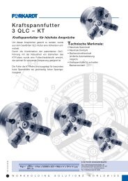
Power <strong>chucks</strong><br />
• Highly developed universal chuck<br />
• With open centre, centrifugal force<br />
compensation and integrated lubricant reserve<br />
• Precise finish-machining at maximum speeds<br />
• Chuck variants for diverse applications<br />
type QLC/KS with extremely large bore<br />
type QLC/LS with very long clamping stroke<br />
type QLC/AG for compensating clamping<br />
type QLC/KT the solid version for highest<br />
standards<br />
Special chucking systems<br />
• Specially designed and manufactured<br />
to customer requirements<br />
• Combined centering and clamping function<br />
for precise driving<br />
• Example: Axle chuck for car body parts<br />
• Sealed and oil-filled for continuous duty<br />
Precision power <strong>chucks</strong><br />
for grinding and hard turning<br />
• Hermetically sealed, with permanent<br />
lubrication for freedom from maintenance<br />
and wear<br />
• Chucking repeat accuracy < 0.0025 mm<br />
• Jaw changing without loss of accuracy<br />
Expanding mandrels/Collets<br />
• Clamping range between 12.5-178.0 mm<br />
• Double angle collet system with split sleeves<br />
• Variable range for the development of optimal<br />
clamping systems<br />
• Ground to customer requirements<br />
SKM<br />
3 QLC/K<br />
family<br />
Special <strong>chucks</strong><br />
High-precision<br />
<strong>chucks</strong><br />
W O R K H O L D I N G S O L U T I O N S W O R L D W I D E<br />
EM<br />
110.10.07 E 01/09<br />
11
BUSINESS<br />
PARTNER<br />
L O C A T I O N S W O R L D W I D E<br />
FORKARDT DEUTSCHLAND GMBH<br />
Heinrich-Hertz-Str. 7<br />
D-40699 Erkrath<br />
Phone: (+49) 211-25 06-0<br />
Fax: (+49) 211-25 06-221<br />
E-Mail: info@forkardt.com<br />
BUCK CHUCK<br />
2155 Traversefield Drive<br />
Traverse City, MI 49686<br />
USA<br />
Phone: (+1) 231-995-8312<br />
Fax: (+1) 231-941-2466<br />
E-Mail: buck.forkardt@forkardt.com<br />
FORKARDT SCHWEIZ GMBH<br />
Industriestrasse 3<br />
CH-8307 Effretikon<br />
Phone: (+41) 52-3 55 31 31<br />
Fax: (+41) 52-3 43 52 40<br />
E-Mail: info-ch@forkardt.com<br />
N.A. WOODWORTH<br />
1391 Wheaton Ave. Suite 700<br />
Troy, MI 48083<br />
USA<br />
Toll Free: 800.544.3823<br />
E-Mail: sales@itwworkholding.com<br />
Website: www.itwworkholding.com<br />
FORKARDT FRANCE S.A.R.L.<br />
28 Avenue de Bobigny<br />
F-93135 Noisy le Sec Cédex<br />
Phone: (+33) 1-41 83 12 40<br />
Fax: (+33) 1-48 40 47 59<br />
E-Mail: forkardt.france@forkardt.com<br />
FORKARDT NORTH AMERICA<br />
1391 Wheaton Ave. Suite 700<br />
Troy, MI 48083, USA<br />
Phone: 248-743-4400<br />
800-794-6190<br />
Fax: 248-743-4401<br />
E-Mail: info@forkardtusa.com<br />
© 2009 FORKARDT, Errors and omissions excepted. ITW Workholding-Group is a division of Illinois Tool Works Inc.<br />
www.forkardt.com<br />
www.itwworkholding.com<br />
110.10.07 E 01/09-0.0 FK Printed in Germany