Embedded DSP: Mini Project
Embedded DSP: Mini Project
Embedded DSP: Mini Project

Create successful ePaper yourself
Turn your PDF publications into a flip-book with our unique Google optimized e-Paper software.
Labaratory <strong>Project</strong>: Real-Time Signal Processing with SHARC 21061<br />
Objectives<br />
<strong>Embedded</strong> <strong>DSP</strong>: <strong>Mini</strong> <strong>Project</strong><br />
- Realization of a simple Digital Voice Recorder-<br />
• To become familiar with Visual <strong>DSP</strong>++ and the SHARC-EZ-KIT-Lite.<br />
• Learn to program and use a control flow.<br />
• Learn how to use interrupt driven I/O.<br />
• Learn how to use I/O by polling mode.<br />
• Learn to use Codec functions.<br />
<strong>Embedded</strong> Systems 2002/2003 (c) Daniel Kästner. 1
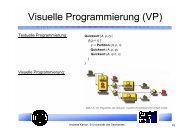
SHARC-Kit Lite<br />
A D<br />
<strong>DSP</strong><br />
Flash<br />
Eprom<br />
Interface<br />
D A<br />
A simple MCU controlled<br />
embedded system<br />
Voice Stick<br />
<strong>Embedded</strong> Systems 2002/2003 (c) Daniel Kästner. 2
<strong>Embedded</strong> <strong>DSP</strong>: <strong>Mini</strong> <strong>Project</strong><br />
• The Voice Recorder should be able to store 3 records which means that 3<br />
buffers are necessary.<br />
• Two records use a DM-data buffer with max. 5600 data samples.<br />
• One record use a data buffer in the PM-memory.<br />
• The sampling rate should be 5.512 KHz (5512 samples/second).<br />
Data recording by FLAG1:<br />
• Each record (1,2,3) automatically uses the corresponding DM-buffer or PMbuffer<br />
(1,2,3).<br />
• The record in process automatically stops when the buffer end is reached.<br />
• A record should be started with the pushbutton FLAG1, which means that FLAG1<br />
is set as an input (refer to internal SHARC register mode2).<br />
– How to modify the register mode2 by C or Assembler ?<br />
– How to read the Input switch FLAG1 by polling mode ?<br />
– How to debounce the switch by software ?<br />
• The record should be indicated by LED FLAG3, which means that FLAG3 is set<br />
as an output (refer to internal SHARC register mode2).<br />
– How to modify the register mode2 by C or Assembler ?<br />
– How to set the FLAG3 output to a certain visble time (blink...) ?<br />
<strong>Embedded</strong> Systems 2002/2003 (c) Daniel Kästner. 3
Data recording by FLAG1:<br />
<strong>Embedded</strong> <strong>DSP</strong>: <strong>Mini</strong> <strong>Project</strong><br />
Indications<br />
• Start of record should be indicated by setting the LED/FLAG3 to -ON-.<br />
• End of record should be indicated by clearing the LED/FLAG3 to -OFF-.<br />
– How to set the FLAG3 output during record ?<br />
Optical indication of a record :<br />
Record time: FLAG 3 is -ON-<br />
RECORD<br />
<strong>Embedded</strong> Systems 2002/2003 (c) Daniel Kästner. 4
<strong>Embedded</strong> <strong>DSP</strong>: <strong>Mini</strong> <strong>Project</strong><br />
Exercise: Development of a Digital Voice Recorder with the SHARC-Kit<br />
Play back by FLAG2:<br />
• Each record (1,2,3) should be started for play back by pushbutton FLAG2, which<br />
means that FLAG2 is set as an input.<br />
– How to modify the register mode2 by C or Assembler ?<br />
– How to read the Input switch FLAG2 by polling mode ?<br />
– How to debounce the switch by software ?<br />
• The start and the end of a play back should be indicated by LED FLAG3, which<br />
means that FLAG3 is set to output (refer to internal SHARC register mode2).<br />
– How to modify the register mode2 by C or Assembler ?<br />
– How to set the FLAG3 output to a certain visble time (blink...) ?<br />
• Playing back of a selected record (1,2,3) should be indicated by a blink mode of<br />
LED/FLAG3.<br />
– How to modify the register mode2 by C or Assembler ?<br />
– How to set the FLAG3 output to a certain visble time (blink...) ?<br />
<strong>Embedded</strong> Systems 2002/2003 (c) Daniel Kästner. 5
<strong>Embedded</strong> <strong>DSP</strong>: <strong>Mini</strong> <strong>Project</strong><br />
Exercise: Development of a simple Digital Voice Recorder with the SHARC-Kit<br />
Optical indication of Play back:<br />
Play back<br />
Play back time: FLAG 3 is -ON-OFF-ON-OFF.....-<br />
<strong>Embedded</strong> Systems 2002/2003 (c) Daniel Kästner. 6
<strong>Embedded</strong> <strong>DSP</strong>: <strong>Mini</strong> <strong>Project</strong><br />
Selecting a buffer for recording or play-back mode:<br />
• A consecutive record should be selected by the pushbutton IRQ1. At the start of<br />
the programm the first buffer is selected by default.<br />
• The pushbutton IRQ1 is linked to the external interrupt IRQ1 of the SHARC.<br />
• By pressing this pushbutton the next buffer should be automatically selected. By<br />
each pressing of the pushbutton the pointer for the next buffer should<br />
recirculate according to the count of the used number of records(1,2,3,1,2,3,...).<br />
– How to use the IRQ1 by C or Assembler ?<br />
– How write and implement an interrupt service routine ?<br />
Automatic record controlled by a programmed sound-level<br />
• Controlled by a software switch<br />
• If used the FLAG1 enables the record.<br />
• The record will be started by crossing over the programmed threshold-level.<br />
<strong>Embedded</strong> Systems 2002/2003 (c) Daniel Kästner. 7
Control flow for the application:<br />
<strong>Embedded</strong> <strong>DSP</strong>: <strong>Mini</strong> <strong>Project</strong><br />
• Start program<br />
• Select buffer 1,2 or 3<br />
• Select mode record or mode play-back<br />
• Do it: Record or play back<br />
• Wait for end of record or end of play-back<br />
• Continue<br />
• The program has to be embedded in the control flow of the CODEC-function.<br />
• Codec: Read/Write by IRQ2, Reset by FLAG0<br />
• The functionality of setting gain and sample rate as done in tt.c should be<br />
preseved.<br />
• Take as a basic program the file tt.c from the demonstration software.<br />
• The words from the CODEC are in 16 bit format. To increase the memory<br />
storage the data have to be packed in MSW and LSW format. Two words of the<br />
CODEC (16 Bit) are stored in one memory location (SHIFT-operation).<br />
<strong>Embedded</strong> Systems 2002/2003 (c) Daniel Kästner. 8
Used ressources:<br />
•FLAG inputs<br />
• (FLAG1, FLAG2)<br />
• FLAG output (FLAG3)<br />
•LED indication<br />
• IRQ1 interrupt input<br />
SW: FLAG2<br />
(IN)<br />
<strong>Embedded</strong> <strong>DSP</strong>: <strong>Mini</strong> <strong>Project</strong><br />
SW: FLAG1<br />
(IN)<br />
SW: IRQ1<br />
(IN)<br />
FLAG3 (OUT)<br />
<strong>Embedded</strong> Systems 2002/2003 (c) Daniel Kästner. 9
Steps of development:<br />
<strong>Embedded</strong> <strong>DSP</strong>: <strong>Mini</strong> <strong>Project</strong><br />
• Create a new folder \recorder\ in the directory \demo\.<br />
• Copy all files from \tt\ to \recorder\.<br />
• Start Visual <strong>DSP</strong>++ and update the environment settings according to the new directory.<br />
• Use the tt.c as the basic program for the new program.<br />
• Modify in the file tt.ldf the target memory definition according to the requirements of the<br />
used buffer.<br />
– C-Compiler is realized by an Runtime Header Model which is connected to the Loader-<br />
Description-File for the target hardware system.<br />
• The following default segments from tt.ldf should be used; the DM memory area has to be<br />
modified.<br />
– seg_rth (PM memory: Interrupt table/runtime header)<br />
– seg_init (PM memory: code)<br />
– seg_pmco (PM memory: data)<br />
– seg_dmda (DM memory: data) (has to be modify for <strong>Mini</strong><strong>Project</strong> !)<br />
– seg_heap (DM memory: heap space) (has to be modify for <strong>Mini</strong><strong>Project</strong> !)<br />
– seg_stack (DM memory: stack space) (has to be modify for <strong>Mini</strong><strong>Project</strong> !)<br />
– Decrease the dm memory size of stack and heap.<br />
– Increase the dm memory size for the 3 buffer !<br />
<strong>Embedded</strong> Systems 2002/2003 (c) Daniel Kästner. 10
<strong>Embedded</strong> <strong>DSP</strong>: <strong>Mini</strong> <strong>Project</strong><br />
• Build a state diagram with the states record, play back and skip buffer.<br />
• Develope the program and test the functionality on the EZ-KIT-Lite.<br />
<strong>Embedded</strong> Systems 2002/2003 (c) Daniel Kästner. 11
<strong>Embedded</strong> <strong>DSP</strong>: SHARC programming<br />
Control/Status Register of SHARC-processor<br />
• Some of the registers are located in the processor core, called system registers.<br />
• System register are a subset of the universal register.<br />
• The core system register are:<br />
– MODE1, MODE2, ASTAT, STKY, IMASK, IMASKP, USTAT1 and USTAT2<br />
• The remaining control registers are located in SHARCs I/O processor (IOP).<br />
– These includes the SYSCON and SYSTAT registers, which are memory-mapped in the<br />
internal memory.<br />
• They can be written from an intermediate field in an instruction or they can be<br />
loaded from or stored to a data memory.<br />
• They also can be transfered to or from any other universal register in one cycle.<br />
<strong>Embedded</strong> Systems 2002/2003 (c) Daniel Kästner. 12
(<strong>Project</strong>)<br />
(<strong>Project</strong>)<br />
(<strong>Project</strong>)<br />
<strong>Embedded</strong> <strong>DSP</strong>: SHARC programming<br />
System register (Core Processor)<br />
• Are a subset of the universal register set.<br />
• They can be written from an intermediate field in an instruction or they can be<br />
loaded from or stored to a data memory.<br />
• They also can be transfered to or from any other universal register in one cycle.<br />
MODE1 Mode control bits<br />
MODE2 Mode control bits<br />
IRPTL Interrupt latch<br />
IMASK Interrrupt mask<br />
IMASKP Interrupt mask pointer for<br />
nesting<br />
ASTAT Arithmetic status register<br />
STKY Sticky status flags<br />
USTAT1 User-defined status flags<br />
USTAT2 User-defines status flags<br />
• The system register bit manipulation instruction can be used to<br />
set, clear, toggle, or test specific bits in the system registers.<br />
• An immediate field in the bit manipulation instruction specifies<br />
the affected bits.<br />
• No transfer via the register file is necessary !<br />
Bit manipulation ALU/Shifter Bit manipulation<br />
BIT SET register data Rn=BSET Rx BY Ry |data<br />
BIT CLR register data Rn=BCLR Rx BY Ry |data<br />
BIT TGL regsiter data Rn=BTGL Rx BY Ry |data<br />
BIT TST register data BTST Rx BY Ry |data<br />
• Examples:<br />
– BIT SET MODE2 0x000000070;<br />
– BIT TST ASTAT 0x000002000;<br />
<strong>Embedded</strong> Systems 2002/2003 (c) Daniel Kästner. 13
MODE2:<br />
<strong>Embedded</strong> <strong>DSP</strong>: SHARC programming<br />
Bit Name Definition <strong>Mini</strong> <strong>Project</strong><br />
(M odifications)<br />
0 IRQ0E 1=edge sensitive, 0=level sensitive<br />
1 IRQ1E 1=edge sensitive, 0=level sensitive 1<br />
2 IRQ2E 1=edge sensitive, 0=level sensitive<br />
3 Reserved<br />
4 CADIS Cache disable<br />
5 TIMEN Timer enable According to<br />
the program flow<br />
6 BUSLK External bus lock (multiprocessor systems)<br />
7-14 Reserved<br />
15 FLG0O FLAG0 1=output, 0=input<br />
16 FLG1O FLAG1 1=output, 0=input 0<br />
17 FLG2O FLAG2 1=output, 0=input 0<br />
18 FLG3O FLAG3 1=output, 0=input 1<br />
19 CAFRZ Cache freeze<br />
20-27 Reserved<br />
28-29 Silicon revision<br />
30-31 Processor ID<br />
<strong>Embedded</strong> Systems 2002/2003 (c) Daniel Kästner. 14
ASTAT:<br />
<strong>Embedded</strong> <strong>DSP</strong>: SHARC programming<br />
Bit Name Definition <strong>Mini</strong> <strong>Project</strong><br />
(M odifications)<br />
0 AZ ALU result zero or floating-point<br />
underflow<br />
1 AV ALU overflow<br />
2 AN ALU result negative<br />
3 AC ALU fixed point carry<br />
4 AS ALU x input signs (ABS and MANT op.)<br />
5 AI ALU floating-point invalid operation<br />
6 MN Multiplier result negative<br />
7 MV Multiplier overflow<br />
8 MU Multiplier floating-point underflow<br />
9 MI Multiplier floating-point invalid operation<br />
10 AF ALU floating point operation<br />
11 SV Shifter overflow<br />
12 SZ Shifter result zero<br />
13 SS Shifter input sign<br />
14-17 Reserved<br />
18 BTF Bit test flag for system register<br />
19 FLAG0 FLAG0 Value<br />
20 FLAG1 FLAG1 Value Input<br />
21 FLAG2 FLAG2 Value Input<br />
22 FLAG3 FLAG3 Value Output<br />
23 Reserved<br />
24-31 CACC<br />
<strong>Embedded</strong> Systems 2002/2003 (c) Daniel Kästner. 15
<strong>Embedded</strong> <strong>DSP</strong>: SHARC programming<br />
Programming FLAGs:(#include )<br />
• File 21060.h contains basic:<br />
– definitions, functions and macros<br />
– for FLAG- and Timer functionality<br />
• In C: Output function: set_flag(flagx, mode);<br />
Output examples in C:<br />
1) set_flag(SET_FLAG3, SET_FLAG); /* Set Flag output state to 1 */<br />
2) set_flag(SET_FLAG1, TGL_FLAG); /* Toggles Flag1 (0>1 or 1>0) */<br />
3) set_flag8SET_FLAG1, CLR_FLAG); /* Clear Flag output state to 0 */<br />
• In C: Input function: poll_flag_in(flagx, mode);<br />
Input examples in C:<br />
1) poll_flag_in(READ_FLAG1, FLAG_IN_LO_TO_HIGH);<br />
2) poll_flag_in(READ_FLAG1, RETURN_FLAG_STATE);<br />
3) while(1) {<br />
size=poll_flag_in(READ_FLAG2, RETURN_FLAG_STATE);<br />
if(size==0) break;<br />
}<br />
File: 21060.h<br />
.....<br />
int set_flag(int _flag, int _mode);<br />
#define SET_FLAG 0<br />
#define CLR_FLAG 1<br />
#define TGL_FLAG 2<br />
#define TST_FLAG 3<br />
#define SET_FLAG0 0<br />
#define SET_FLAG1 1<br />
#define SET_FLAG2 2<br />
#define SET_FLAG3 3<br />
int poll_flag_in(int _flag, int _mode);<br />
#define READ_FLAG0 0<br />
#define READ_FLAG1 1<br />
#define READ_FLAG2 2<br />
#define READ_FLAG3 3<br />
#define FLAG_IN_LO_TO_HI 0<br />
#define FLAG_IN_HI_TO_LO 1<br />
#define FLAG_IN_HI 2<br />
#define FLAG_IN_LO 3<br />
#define FLAG_IN_TRANSITION 4<br />
#define RETURN_FLAG_STATE 5<br />
.....<br />
<strong>Embedded</strong> Systems 2002/2003 (c) Daniel Kästner. 16
<strong>Embedded</strong> <strong>DSP</strong>: SHARC programming<br />
Programming FLAGs as assembler inline<br />
code in C:(#include )<br />
• File def21060.h contains basic:<br />
– definitions, addresses and bit masks- and<br />
patterns<br />
– cover for all universal registers<br />
Flag output programming as assembler inline code for C<br />
environment:<br />
1)<br />
asm(„#include “);<br />
asm(„bit set mode2 FLG3O;“); /* Set FLAG3 to output */<br />
asm(„bit clr astat FLG3;“); /* FLAG3 =0 */<br />
2)<br />
asm(„bit set mode2 FLG0O|FLG2O|FLG3O|IRQ1E;“);<br />
Flag testing input as assembler inline code for C<br />
environment:<br />
1)<br />
asm(„#include “);<br />
asm(„bit tst astat 0x0008000;“); /* TF = 1 if FLG3 is ‚1‘ */<br />
if TF ........;<br />
2)<br />
if FLAG2_IN ..compute..; /* FLAG2_IN: condirtion code: (if,do) */<br />
if NOT FLAG2_IN ..compute..; /* FLAG2_IN: condirtion code: (if,do) */<br />
File: def21060.h<br />
...<br />
...<br />
/* MODE2 register */<br />
#define IRQ0E 0x00000001 /* Bit 0: IRQ0- 1=edge sens. 0=level sens. */<br />
#define IRQ1E 0x00000002 /* Bit 1: IRQ1- 1=edge sens. 0=level sens. */<br />
#define IRQ2E 0x00000004 /* Bit 2: IRQ2- 1=edge sens. 0=level sens. */<br />
#define CADIS 0x00000010 /* Bit 4: Cache disable */<br />
#define TIMEN 0x00000020 /* Bit 5: Timer enable */<br />
#define BUSLK 0x00000040 /* Bit 6: External bus lock */<br />
#define FLG0O 0x00008000 /* Bit 15: FLAG0 1=output 0=input */<br />
#define FLG1O 0x00010000 /* Bit 16: FLAG1 1=output 0=input */<br />
#define FLG2O 0x00020000 /* Bit 17: FLAG2 1=output 0=input */<br />
#define FLG3O 0x00040000 /* Bit 18: FLAG3 1=output 0=input */<br />
#define CAFRZ 0x00080000 /* Bit 19: Cache freeze */<br />
...<br />
...<br />
/* ASTAT */<br />
...<br />
# define FLG0 0x00080000<br />
# define FLG1 0x00100000<br />
# define FLG2 0x00200000<br />
# define FLG3 0x00400000<br />
...<br />
...<br />
<strong>Embedded</strong> Systems 2002/2003 (c) Daniel Kästner. 17
<strong>Embedded</strong> <strong>DSP</strong>: SHARC programming -Interrupt-<br />
What are interrupts ?<br />
• How programming interrupts ?<br />
• Using a CODEC with interrupts<br />
• Interrupts is an event that causes processor to halt what it is actually doing, and<br />
execute an interrupt service routine (ISR).<br />
• An interrupt forces a subroutine call to a predefined address, the interrupt<br />
vector.<br />
• SHARC-<strong>DSP</strong> assigns a unique vector to each type of interrupt.<br />
• Interrupts are caused by a variety of conditions, both internal and external to<br />
the processor:<br />
– Timers<br />
– External interrupts<br />
– Internal interrupts: DMA (direct memory access)<br />
• A interrupt is not recognized if it is not masked to state -ON-.<br />
• In nested mode a priorization list schedules which interrupt is actually serviced.<br />
<strong>Embedded</strong> Systems 2002/2003 (c) Daniel Kästner. 18
<strong>Embedded</strong> <strong>DSP</strong>: SHARC programming -Interrupt-<br />
SHARC core processor cannot service an interrupt unless it is executing instructions<br />
or is in the special IDLE mode. IDLE is an instruction that halts the processor core<br />
until an external interrupt or the timer interrupt occurs. Interrupt service routines<br />
end with a RTI.<br />
• To process an interrupt, the SHARC program sequencer performs the following actions:<br />
– Outputs the linked vector address.<br />
– Pushes the current PC value (return address) on the stack.<br />
– If the the interrupt source is one of the external IRQs or the VIRPT-IRQ (Multiprocessing), the<br />
sequencer pushes the current value of the ASTAT and MODE1 registers onto the status stack.<br />
– Set the appropriate bit in the interrupt latch register (IRPTL).<br />
– Achanges the interrupt mask pointer (IMASKP) to reflect the current interrupt nesting state. The<br />
nesting mode (NESTM) bit in the MODE1 register determines whether all interupts or only lower<br />
priority interrupts are masked during the servicing routine.<br />
• At the end of an interrupt service routine, the RTI instruction causes the following actions.<br />
– Returns to the address, which was stored at the top of the stack.<br />
– Pops this value off of the stack.<br />
– Pops the status stack if the ASTAT and MODE1 status registers were pushed (see above).<br />
– Clears the appropriate bit in the interrupt latch register (IRPTL) and interrupt mask pointer<br />
(IMASKP).<br />
<strong>Embedded</strong> Systems 2002/2003 (c) Daniel Kästner. 19
<strong>Embedded</strong> <strong>DSP</strong>: SHARC programming -Interrupt-<br />
Register:<br />
IRPTl&IMASK<br />
bit-position<br />
<strong>Mini</strong> <strong>Project</strong> !<br />
Interrupt Vector Table:<br />
• Each is separated by 4<br />
memory locations.<br />
• Represents an offset from a<br />
base address.<br />
• Internal memory:<br />
• base: 0x00020000<br />
• at beginning of block 0<br />
• External memory:<br />
• base: 0x00400000<br />
(def21060.h)<br />
<strong>Embedded</strong> Systems 2002/2003 (c) Daniel Kästner. 20
<strong>Embedded</strong> <strong>DSP</strong>: SHARC programming<br />
Register:<br />
IRPTl&IMASK<br />
<strong>Embedded</strong> Systems 2002/2003 (c) Daniel Kästner. 21
<strong>Embedded</strong> <strong>DSP</strong>: SHARC programming -Interrupt-<br />
Interrupt example in C environment via functions:<br />
• Enable Sport 0 transmit and receive interrupts<br />
• See also the examples from the demo software<br />
SHARC-EZKIT-Lite.<br />
• The used functions are defined in the file signal.h Visual<br />
<strong>DSP</strong>++.<br />
• Nested mode is defined in register mode1.<br />
• Example for Enabling interupt nesting:<br />
......<br />
asm(„include “);<br />
asm(„bit set mode1 NESTM“;);<br />
......<br />
/* Sport 0 Receive Interrupt Service Routine */<br />
void Sport0RcvIsr()<br />
{<br />
sport0_receive_flag = 1;<br />
}<br />
/* Sport 0 Transmit Interrupt Service Routine */<br />
void Sport0TrsIsr()<br />
{<br />
sport0_transmit_flag = 1;<br />
}<br />
...<br />
main()<br />
{<br />
..<br />
setup_sport0(); /* set sport0*/<br />
interrupt (SIG_SPR0I, Sport0RcvIsr);<br />
interrupt (SIG_SPT0I, Sport0TrsIsr);<br />
start_sport0_trs();<br />
start_sport0_rcv();<br />
...<br />
while(1) {<br />
if(sport0_transmit_flag==1) {<br />
sport0_transmit_flag=0;<br />
....<br />
}<br />
if(sport0_receive_flag==1) {<br />
sport0_transmit_flag=0;<br />
....<br />
}<br />
}<br />
}<br />
<strong>Embedded</strong> Systems 2002/2003 (c) Daniel Kästner. 22
<strong>Embedded</strong> <strong>DSP</strong>: SHARC programming -Timer-<br />
• The SHARC includes a programmable interval timer.<br />
• The timer can generate periodic interrupts.<br />
• The timer is controlled via the system register MODE2.<br />
• The two registers TCOUNT and TPERIOD control the<br />
timer interval.<br />
• The register TCOUNT contains the timer counter.<br />
• The timer decrements the TCOUNT register by<br />
each clock cycle.<br />
• When TCOUNT reaches zero, the timer generates<br />
an interrupt and asserts the TIMEXP pin on the chip.<br />
• The TPERIOD register value specifies the frequency<br />
of timer interrupts.<br />
• The number of cycles between interrupts is<br />
(TPERIOD + 1).<br />
• The maximum value is 2 32 -1, so if the clock is 25 ns,<br />
the maximum time interval is 107,375 seconds.<br />
Register Function Width<br />
TPERIOD Timer Period<br />
Register<br />
TCOUNT Timer Counter<br />
Register<br />
<strong>Embedded</strong> Systems 2002/2003 (c) Daniel Kästner. 23<br />
32 bits<br />
32 bits
<strong>Embedded</strong> <strong>DSP</strong>: SHARC programming -Timer-<br />
Timer Enable/Disable:<br />
• To start and stop the timer, the bit TIMEN bit in the register mode2 has to beset or cleared.<br />
• With the timer disabled, a new load of the TCOUNT register can be perfomred as an initial<br />
value.<br />
• The value for the time interval has to be loaded in the register TPERIOD.<br />
• Start the timer by setting the bit TIMEN.<br />
• At reset the timer is always disabled.<br />
Timer interrupts:<br />
• When the value of TCOUNT reaches zero, the timer generates two interrupts.<br />
• One with a relatively high priority<br />
• One with a low priority.<br />
• At reset both are masked out.<br />
• Interrupt priority determines which interrupt is serviced first, when two ocuur in the same<br />
cycle.<br />
• When nesting is enabled, only higher priority interrupts can interrupt a service routine in<br />
progress.<br />
<strong>Embedded</strong> Systems 2002/2003 (c) Daniel Kästner. 24
<strong>Embedded</strong> <strong>DSP</strong>: SHARC programming -Timer-<br />
See also the examples tt.c and blink.c<br />
from the demo software SHARC-EZKIT-<br />
Lite.<br />
Example in C:<br />
/* Periodic time interrupt service routine */<br />
void timer_high_priority(int sig_num)<br />
{<br />
sig_num=sig_num;<br />
set_flag(SET_FLAG3, TGL_FLAG)<br />
timer_flag = 1;<br />
}<br />
main<br />
{<br />
}<br />
....<br />
timer_off(); /* disable timer */<br />
timer_set(1000000,200000); /* program timer */<br />
Interrupt(SIG_TMH, timer_high_priority); /* enable timer IRQ */<br />
....<br />
timer_on(); /* start timer */<br />
....<br />
while(1) {<br />
if(timer_flag=1) {<br />
timer_flag=0;<br />
.....<br />
}<br />
<strong>Embedded</strong> Systems 2002/2003 (c) Daniel Kästner. 25
TT.C<br />
Discussion of the demo program tt.c<br />
by overhead projector<br />
<strong>Embedded</strong> Systems 2002/2003 (c) Daniel Kästner. 26
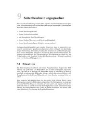
<strong>Embedded</strong> <strong>DSP</strong>: Paced Loop<br />
• The paced loop is a general purpose software structure that is suitable for a<br />
wide range of MCU/<strong>DSP</strong> applications.<br />
• The main idea is to break the complete application into a series of tasks, such<br />
as:<br />
– reading data<br />
– processing data<br />
– storing results<br />
– reading system inputs<br />
– updating system outputs<br />
• Each task is written as a function (subroutine).<br />
• A main loop is realized out of „jump to subroutine“ instruction for each of the<br />
tasks.<br />
• At the top of the loop is a software pacemaker integrated.<br />
• When the pacemaker triggers, the list of task functions is executed one time and<br />
a branch instruction leads to the top of the loop to wait for the next pacemaker<br />
trigger.<br />
<strong>Embedded</strong> Systems 2002/2003 (c) Daniel Kästner. 27
<strong>Embedded</strong> <strong>DSP</strong>: Paced Loop<br />
Pacemaker Trigger Pacemaker Trigger<br />
Function 1 Function 2 Function N<br />
Function 1<br />
Max. Process Time Max. Process Time<br />
Pacemaker Trigger: Timer controlled by software<br />
Function 2<br />
Function N<br />
<strong>Embedded</strong> Systems 2002/2003 (c) Daniel Kästner. 28
<strong>Embedded</strong> <strong>DSP</strong>: Paced Loop<br />
• The top block is a loop that waits for the pacemaker<br />
trigger TIC.<br />
• The next blocks manages a counter TICcnt.<br />
• When the counter TICcnt reachs a limit TICcnt will be<br />
cleared.<br />
• This example acts with two functions (func1 and<br />
func2).<br />
• The limitation of the number of tasks is given by the<br />
condition, that all tasks must finish quickly enough in<br />
order that no trigers are lost.<br />
• The last block in the flowchart is just a branch to the<br />
top of the loop to wait for the next pacemaker trigger.<br />
<strong>Embedded</strong> Systems 2002/2003 (c) Daniel Kästner. 29
<strong>Embedded</strong> <strong>DSP</strong>: Paced Loop<br />
• The pacemaker loop is realized on a real time interrupt, called<br />
TimerIRQ.<br />
• TimerIRQ is programmed to generate an interrupt to the CPU<br />
every K processor cycles.<br />
• The flowchart shows what acts at each TimerIRQ interrupt.<br />
• The interrupt is working asynchronously in respect to the<br />
main program.<br />
• The variable TIC is used as a flag to tell the main program<br />
when it is time to increment the variable TICcnt and to step<br />
one time through the paced loop.<br />
• In this example a variable Tcnt is used to count 4 real time<br />
interrupts before setting TIC to one.<br />
• The main program watchs TIC to see when TIC becomes set.<br />
• Every K processor cycles the timer interrupt flag will get set,<br />
trigering a timer interrupt request.<br />
• One task of the interrupt service routine is to clear the flag<br />
that is responsible for the interrupt before returning from the<br />
interrupt.<br />
• If the timer interrupt flag is not cleared before return, a new<br />
interrupt is generated immediately instead of waiting the next<br />
K time steps.<br />
<strong>Embedded</strong> Systems 2002/2003 (c) Daniel Kästner. 30
<strong>Embedded</strong> <strong>DSP</strong>: Paced Loop<br />
• The variable TICcnt is important for the pacemaker.<br />
• TICcnt counts in this example from 0 to 20.<br />
• As TICcnt increments from 19 to 20 , the program watches this and resets<br />
TICcnt within the pacemaker itself.<br />
• TICcnt appears to count ftom 0 to 19; FLAG is equal to 0 on every twenth<br />
trigger of the pacemaker.<br />
• Function#1 is the first task in the main loop and maintains a slower clock called<br />
TOC, which is incremented each time the paced loop executes and TICcnt is 0<br />
(every 20. Pass through the loop).<br />
• TOC is a software counter that counts from 0 to K.<br />
• The task function#2 can use the current values of TICcnt and TIC to decide<br />
which action needs to be done on this pass activated by the paced loop.<br />
<strong>Embedded</strong> Systems 2002/2003 (c) Daniel Kästner. 31
<strong>Embedded</strong> <strong>DSP</strong>: Paced Loop<br />
• Some restrictions on the task functions:<br />
• Each task function should do everything as quickly as possible.<br />
• The total time required to execute one pass through all of the task functions<br />
must be less than 2 pacemaker triggers.<br />
<strong>Embedded</strong> Systems 2002/2003 (c) Daniel Kästner. 32
More complicated example:<br />
<strong>Embedded</strong> <strong>DSP</strong>: Dispatcher<br />
• Interrupt driven command dispatcher<br />
• Interrupt routine: irq0_handler sets the<br />
event to 1 and reads a command from<br />
a communication channel.<br />
• The switch loop peforms the corresponding<br />
comand driven function.<br />
interrupt(SIG_IRQ0,irq0_handler);<br />
..<br />
..<br />
..<br />
while(1)<br />
{<br />
idle();<br />
if (EventPC==1)<br />
{<br />
EventPC=0;<br />
switch(buffer.msg.cmd)<br />
{<br />
case LOAD_KOEFF:<br />
...<br />
case WAVELET:<br />
...<br />
case DATAPC_<strong>DSP</strong>:<br />
...<br />
case FFT:<br />
...<br />
case EXTERN:<br />
...<br />
case EXIT:<br />
...<br />
}<br />
}<br />
<strong>Embedded</strong> Systems 2002/2003 (c) Daniel Kästner. 33
<strong>Embedded</strong> <strong>DSP</strong>: Dispatcher<br />
No Interrupt<br />
INIT<br />
IDLE<br />
PC _EVENT=0<br />
CM ND<br />
Func()<br />
EXIT<br />
Interrupt<br />
<strong>Embedded</strong> Systems 2002/2003 (c) Daniel Kästner. 34<br />
IRQ<br />
PC _EVENT=1<br />
• Reads the content of a buffer<br />
• Interprete the comand.<br />
• executes the corresponding function.
process in wait<br />
Event<br />
IR 1<br />
prozess<br />
prozess<br />
process<br />
Scheduler<br />
Event FIFO Event<br />
IR 2<br />
Data<br />
active process<br />
IR 3<br />
Process Layer<br />
Interrupt<br />
Layer<br />
<strong>Embedded</strong> Systems 2002/2003 (c) Daniel Kästner. 35
Start<br />
Init<br />
state 0<br />
wait on<br />
EVENT<br />
Scheduler<br />
EVENT<br />
determine<br />
Interrupt<br />
call<br />
process N<br />
Exit<br />
determine<br />
Interrupt<br />
check<br />
IRQ-Array and<br />
Interrupts<br />
determine<br />
highest<br />
Interrupt<br />
update<br />
IRQ-Array<br />
more IRQs<br />
or array not<br />
empty<br />
NEIN<br />
set<br />
EVENT=0<br />
<strong>Embedded</strong> Systems 2002/2003 (c) Daniel Kästner. 36<br />
Exit<br />
Y