Hier steht Ihr Text - G. Bee GmbH
Hier steht Ihr Text - G. Bee GmbH
Hier steht Ihr Text - G. Bee GmbH

Create successful ePaper yourself
Turn your PDF publications into a flip-book with our unique Google optimized e-Paper software.
G.<strong>Bee</strong> <strong>GmbH</strong><br />
Kugelhähne & Sicherheitsarmaturen<br />
Ball Valves & Safety Valves<br />
G.<strong>Bee</strong> <strong>GmbH</strong> . Postfach 1161 . 71687 Freiberg a.N. . Germany<br />
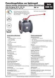
Bedienungs- und Montageanleitung für Armaturen der Baureihe KSN 75 TAS<br />
1. Anwendungsbereich<br />
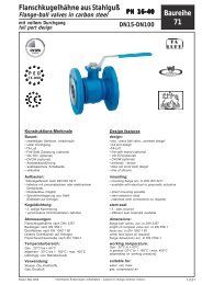
Gas-Absperrarmatur mit thermischer Armaturensicherung (TAS) für max. Betriebsdruck MOP 5.<br />
Für Betriebsdrücke von 5 bis 16bar müssen hochwarmfeste Schrauben (650°C) verwendet werden.<br />
Hinweis:<br />
Die Armatur mit Selbstauslösender thermischer Armaturensicherung (TAS) muss gem. der Anwendung mit<br />
DIN-DVGW oder CE-Ident-Nr. gekennzeichnet sein.<br />
1.1 Installationsbereich Gase nach DIN EN 437 G260/1:<br />
DIN EN 13774, DIN 3586 PED 97/23/EG CE-0085<br />
DIN-DVGW-Reg.-Nr. = DG-4341AT2765<br />
1.2 Absperrarmatur gem. der Gasgeräterichtlinie 90/396/EWG:<br />
CE-Ident.-Nr. CE-0085AU2377<br />
2. Einbau / Montage<br />
Die Kugelhahn TAS Kombination wird grundsätzlich in Offenstellung geliefert.<br />
Der Einbau soll in der Regel auch in Offenstellung erfolgen. Die Durchflussrichtung ist zu beachten. Die Montage<br />
muss fachgerecht nach Anforderungen der TRGI 2008 durchgeführt werden.<br />
Der Temperaturfühler darf keinen mechanischen Belastungen ausgesetzt werden.<br />
Armaturen mit ausgelöster TAS bzw. beschädigtem Temperaturfühler dürfen nicht montiert werden.<br />
Zur Abdichtung der Flanschverbindung ( eingangsseitig ) muss generell eine geeignete temperaturbeständige<br />
Flachdichtungen ( HTB – Dichtung ) Verwendung finden.<br />
Dies gilt für alle Flanschverbindungen des Brandabschnittes vor der TAS.<br />
Für Betriebsdrücke über MOP5 bis max. PN16 müssen alle Flanschverbindungen des zu sichernden<br />
Brandabschnittes mit hochwarmfesten Schrauben und Muttern ausgeführt werden.<br />
Die Verbindung muss fachgerecht mit folgenden Anziehmomenten verschraubt werden.<br />
M10 mit 32Nm; M16 mit 135Nm; M20 mit 280Nm. ( Siehe Montageanleitung Montage-Set ).<br />
Die Nennweite DN 150 kann nur mit offener Kugelstellung montiert werden.<br />
Armaturen sollen nicht den Spannungen des Leitungssystems ausgesetzt sein, da ansonsten die Funktion negativ<br />
beeinträchtigt werden kann. Nach dem Einbau ist ein Reinigungsvorgang des Leitungssystems erforderlich, um<br />
Installationsrückstände zu entfernen und eine eventuelle Beschädigung der integrierten TAS als auch der<br />
Kugeldichtung zu verhindern.<br />
Farbanstriche, Isolierungen, Schutzverkleidungen usw. sind unzulässig.<br />
3. Bedienung<br />
Schließen: 90° Drehung des Bedienungshebels im Uhrzeigersinn.<br />
Öffnen: 90° Drehung des Bedienungshebels gegen den Uhrzeigersinn.<br />
Die Eingefräste Kerbe der Schaltspindel zeigt die Kugelstellung - Offen / Geschlossen an.<br />
Der Kugelhahn darf nur in Offen- oder Geschlossenstellung betrieben werden.<br />
Zwischenstellungen ( Regelfunktion ) beschädigen die Kugeldichtung.<br />
Dies kann zur Undichtheit in der Absperrfunktion führen.<br />
Die Armatur ist vor Temperaturen über 60°C ( z.B. Sonneneinstrahlung ) zu schützen,<br />
da die integrierte thermische Armaturensicherung auslösen kann und somit den Durchfluss<br />
verschließt. ( Auslösetemperatur 95°C +/- 5°C )<br />
4. Wartung<br />
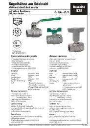
<strong>Bee</strong> Armaturen sind wartungsfrei.<br />
5. Sonstiges<br />
Bei unsachgemäßer Montage oder/und Bedienung erlischt jeglicher Gewährleistungsanspruch.<br />
Im Reparaturfall darf die Kugelhahn TAS Kombination nur im Herstellerwerk geöffnet werden.<br />
Herstellererklärung:<br />
Dieses Produkt wurde gemäß den technischen Richtlinien und DIN-Normen hergestellt.<br />
Die zur Herstellung unserer Produkte verwendeten Werkstoffe entsprechen den Vorschriften<br />
nach DIN. Wir erklären die Konformität mit der EG-Gasgeräterichtlinie (90/396/EWG)<br />
und bescheinigen, dass BEE Armaturen dem Baumustergeprüften Produkt entsprechen. Stand: 25.03.2011<br />
Hausanschrift:<br />
Robert-Bosch-Straße 14<br />
71691 Freiberg a.N.<br />
Telefon: +49 (0) 7141 -9744 -0<br />
Telefax: +49 (0) 7141-9744-155<br />
E-Mail: info@g-bee.de<br />
Germany Internet: www.g-bee.de<br />
USt-IdNr.: DE144958516<br />
Banken:<br />
Kreissparkasse Ludwigsburg (BLZ 60450050) 7008816<br />
IBAN DE52 6045 0050 0007 0088 16 . SWIFT/BIC: SOLA DE S1 LBG<br />
Volksbank Ludwigsburg (BLZ 60490150) 430076002<br />
IBAN DE30 6049 0150 0430 0760 02 . SWIFT: GENO DE S1 LBG<br />
BW-Bank (BLZ 60050101) 8183235<br />
IBAN DE88 6005 0101 0008 1832 35 . SWIFT: SOLA DE ST<br />
Postbank Stuttgart (BLZ 60010070) 4990-701<br />
IBAN DE21 6001 0070 0004 9907 01 . SWIFT/BIC: PBNK DE FF<br />
Rechtsgültige Firmierung:<br />
G.<strong>Bee</strong> <strong>GmbH</strong><br />
Sitz:<br />
Freiberg am Neckar,<br />
Robert-Bosch-Straße 14<br />
Amtsgericht Stuttgart HRB 300 631<br />
Geschäftsführer:<br />
Dipl.-Ing. Norbert Layer
G.<strong>Bee</strong> <strong>GmbH</strong><br />
Kugelhähne & Sicherheitsarmaturen<br />
Ball Valves & Safety Valves<br />
G.<strong>Bee</strong> <strong>GmbH</strong> . Postfach 1161 . 71687 Freiberg a.N. . Germany<br />
Konformitätserklärung<br />
gemäß Anhang 7 der Druckgeräterichtlinie 97/23EG<br />
Hersteller: G. <strong>Bee</strong> <strong>GmbH</strong><br />
Robert-Bosch-Straße 14<br />
D-71691 Freiberg a. N.<br />
Beschreibung:<br />
Kugelhahn mit eingangsseitig integrierter thermischer Armaturensicherung „TAS“,<br />
zur Absperrung und thermischer Absicherung Nachgeschalteter Objekte in der<br />
Gasinstallation. ( Druckhaltendes Ausrüstungsteil )<br />
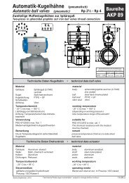
Typbezeichnung: KSN 75 – DN – TAS<br />
Angewandte Konformitätsbewertungsverfahren:<br />
Modul H ( Umfassende Qualitätssicherung ) benannte Stelle TÜV Rheinland ( CE0035 )<br />
Angewandte Regelwerke:<br />
Einteilung Regelwerke<br />
Werkstoffe AD2000 – W3/2<br />
Auslegung AD2000 – A4, DIN 3840<br />
Flanschanschluss EN-1092-1<br />
Baulänge EN-558-1<br />
Montageflansch ISO-5211<br />
Anwendungsbedingte<br />
DIN EN 13774 -DIN3586<br />
Regelwerke<br />
Prüfungen DIN EN 12266, DIN3230-5,<br />
Elastomere EN 682, (DIN3535-3)<br />
Kennzeichnung EN 19 PED 97/23/EG GAD 90/396/EWG<br />
Wir erklären, dass das Produkt mit der Richtlinie 97/23/EG übereinstimmt und oben genannten<br />
Konformitätsbewertungsverfahren unterzogen wurde.<br />
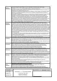
Gefahrenanalyse:<br />
Der Kugelhahn mit eingansseitig integrierter TAS ist auf Belastungen ausgelegt, die der beabsichtigten<br />
Verwendung und anderen nach vernünftigem Ermessen vorhersehbaren Betriebsbedingungen angemessen<br />
ist. Insbesondere sind folgende Faktoren zu berücksichtigen.<br />
Druckbelastung: Die Druckbelastung muss in dem angegebenen Druckbereich liegen.<br />
Gegen eine Drucküberschreitung sowie Druckschläge sind geeignete Maßnahmen zu ergreifen.<br />
Zu Prüfzwecken kann die Armatur mit 1.5xNenndruck beaufschlagt werden.<br />
Temperaturbelastung:<br />
Die Umgebungstemperatur darf 60°C nicht überschreiten, da ansonsten die thermische<br />
Armaturensicherung auslöst und den Durchfluss absperrt. Auslösetemperatur 95°±5°<br />
Ausgelöste TAS müssen erneuert werden.<br />
Beständigkeit gegenüber dem Medium: Alle Werkstoffe sind auf dem Datenblatt aufgeführt.<br />
Die chemische Verträglichkeit muss sichergestellt sein.<br />
Reaktionskräfte: Reaktionskräfte und –Momente im Zusammenhang mit Trageelementen, Rohrleitungen<br />
Befestigungen usw. dürfen die in DIN EN 13774 aufgeführten Momente nicht überschreiten.<br />
Durch Auslegung und Bau muss folgendes sichergestellt sein:<br />
Der Gefahr einer Überbeanspruchung durch unzulässige Bewegung oder übermäßige Kräfte z.B. an<br />
Armaturen ist durch Unterstützung, Befestigung, Ausrichtung in geeigneter Weise vorzubeugen.<br />
Bei gasförmigen Fluiden die Kondensflüssigkeiten bilden sind geeignete Einrichtungen zur Entwässerung zur<br />
Vermeidung von Schäden durch Wasserschlag und Korrosion vorzusehen. Die Gefahr von<br />
Ermüdungserscheinungen durch Vibration des Rohrleitungssystems ist gebührend zu berücksichtigen.<br />
Hausanschrift:<br />
Robert-Bosch-Straße 14<br />
71691 Freiberg a.N.<br />
Telefon: +49 (0) 7141 -9744 -0<br />
Telefax: +49 (0) 7141-9744-155<br />
E-Mail: info@g-bee.de<br />
Germany Internet: www.g-bee.de<br />
USt-IdNr.: DE144958516<br />
Banken:<br />
Kreissparkasse Ludwigsburg (BLZ 60450050) 7008816<br />
IBAN DE52 6045 0050 0007 0088 16 . SWIFT/BIC: SOLA DE S1 LBG<br />
Volksbank Ludwigsburg (BLZ 60490150) 430076002<br />
IBAN DE30 6049 0150 0430 0760 02 . SWIFT: GENO DE S1 LBG<br />
BW-Bank (BLZ 60050101) 8183235<br />
IBAN DE88 6005 0101 0008 1832 35 . SWIFT: SOLA DE ST<br />
Postbank Stuttgart (BLZ 60010070) 4990-701<br />
IBAN DE21 6001 0070 0004 9907 01 . SWIFT/BIC: PBNK DE FF<br />
Stand: 25.03.2011<br />
Rechtsgültige Firmierung:<br />
G.<strong>Bee</strong> <strong>GmbH</strong><br />
Sitz:<br />
Freiberg am Neckar,<br />
Robert-Bosch-Straße 14<br />
Amtsgericht Stuttgart HRB 300 631<br />
Geschäftsführer:<br />
Dipl.-Ing. Norbert Layer
G.<strong>Bee</strong> <strong>GmbH</strong><br />
Kugelhähne & Sicherheitsarmaturen<br />
Ball Valves & Safety Valves<br />
G.<strong>Bee</strong> <strong>GmbH</strong> . Postfach 1161 . 71687 Freiberg a.N. . Germany<br />
Operating and assembly instructions for valves series KSN 75 TAS<br />
1. Field of application<br />
Gas shut-off valve with thermal release (TAS) for maximum operating pressure MOP 5.<br />
For operating pressures of 5 to 16bar high-temperature resistant bolts (650°C) must be used.<br />
Note:<br />
The valve with automatic thermal release (TAS) must be marked according to its use with DIN-DVGW or CE<br />
Identification No.<br />
1.1 Installation area gases in accordance with DIN EN 437 G260-1:<br />
DIN EN 13774, DIN 3586 PED 97/23/EC CE-0085<br />
DIN-DVGW Reg. No. = DG-4341AT2765<br />
1.2 Shut-off valve in accordance with th e Gas Installations Directive 90/396/EEC:<br />
CE Identification No. CE-0085AU2377<br />
2. Installation / Assembly<br />
The ball valve TAS combination is basically supplied in the open position.<br />
As a general rule it should also be installed in the open position. The direction of flow must be heeded.<br />
Assembly must be carried out correctly according to the specifications of the TRGI 2008<br />
The temperature gauge must not be subject to any mechanical stresses.<br />
Valves with a tripped TAS or a damaged temperature gauge must not be assembled.<br />
To seal the flange connection (supply side) it is generally necessary to use a suitably heat-resistant flat gasket.<br />
(HTB seal).<br />
This applies to all flange connections of the fire section in front of the TAS.<br />
For operating pressures above MOP5 up to a maximum of PN16 all flange connections of the fire section to<br />
be protected must be executed with high-temperature resistant bolts and nuts.<br />
The connection must be bolted correctly with the following tightening moments.<br />
M10 with 32Nm; M16 with 135Nm; M20 with 280Nm. (See Assembly instructions for assembly kit).<br />
The nominal width DN 150 can only be assembled with the ball in the open position.<br />
Valves should not be subject to the stresses of the pipe system, as their function may otherwise be impaired.<br />
Following installation the pipe system must be flushed out in order to remove any residual matter and to<br />
prevent possible damage to the integrated TAS and the ball seal.<br />
Coats of paint, insulation and protective coverings etc., are not permitted.<br />
3. Operation<br />
To close: Turn the operating lever 90° clockwise.<br />
To open: Turn the operating lever 90° anti-clockwise.<br />
The notch in the switch spindle indicates the ball position - Open / Closed.<br />
The ball valve may only be operated in Open or Closed position.<br />
Intermediate positions (control function) can damage the ball seal.<br />
This can cause leakage in the shut-off function.<br />
The valve must be protected from ambient temperatures above 60°C (e.g., sun rays), since this may trip the<br />
integrated thermal release and thus shut off the flow. (Tripping temperature 95°C +/-5°C)<br />
4. Maintenance<br />
BEE fittings need no maintenance.<br />
5. Miscellaneous<br />
Incorrect assembly and/or operation will invalidate the right to make claims under the warranty.<br />
In the event of repair the ball valve TAS combination may only be opened in the manufacturer's plant.<br />
Declaration of the manufacturer:<br />
This product has been manufactured in accordance with the technical guidelines and DIN standards.<br />
The materials used to manufacture our products conform to DIN legislation. We hereby declare that they<br />
conform to the EC Gas Installations Directive (90/396/EEC) and confirm that BEE valves correspond to the<br />
design type-tested product.<br />
stand: 25.03.2011<br />
Hausanschrift:<br />
Robert-Bosch-Straße 14<br />
71691 Freiberg a.N.<br />
Telefon: +49 (0) 7141 -9744 -0<br />
Telefax: +49 (0) 7141-9744-155<br />
E-Mail: info@g-bee.de<br />
Germany Internet: www.g-bee.de<br />
USt-IdNr.: DE144958516<br />
Banken:<br />
BW-Bank (BLZ 60050101) 8183235<br />
IBAN DE88 6005 0101 0008 1832 35 . SWIFT: SOLA DE ST<br />
Postbank Stuttgart (BLZ 60010070) 4990-701<br />
IBAN DE21 6001 0070 0004 9907 01 . Kreissparkasse Ludwigsburg (BLZ 60450050) 7008816<br />
IBAN DE52 6045 0050 0007 0088 16<br />
SWIFT/BIC: PBNK DE FF<br />
. SWIFT/BIC: SOLA DE S1 LBG<br />
Volksbank Ludwigsburg (BLZ 60490150) 430076002<br />
IBAN DE30 6049 0150 0430 0760 02 . SWIFT: GENO DE S1 LBG<br />
Rechtsgültige Firmierung:<br />
G.<strong>Bee</strong> <strong>GmbH</strong><br />
Sitz:<br />
Freiberg am Neckar,<br />
Robert-Bosch-Straße 14<br />
Amtsgericht Stuttgart HRB 300 631<br />
Geschäftsführer:<br />
Dipl.-Ing. Norbert Layer
G.<strong>Bee</strong> <strong>GmbH</strong><br />
Kugelhähne & Sicherheitsarmaturen<br />
Ball Valves & Safety Valves<br />
G.<strong>Bee</strong> <strong>GmbH</strong> . Postfach 1161 . 71687 Freiberg a.N. . Germany<br />
Declaration of conformity<br />
in accordance with Appendix 7 of the Pressure Equipment Directive 97/23EC<br />
Manufacturer: G. <strong>Bee</strong> <strong>GmbH</strong><br />
Robert-Bosch-Straße 14<br />
D-71691 Freiberg a. N.<br />
Description: Ball valve with integrated "TAS" thermal release on the supply side for shut-off and thermal protection<br />
of objects connected on the load side in the gas installation. (pressure-maintaining plant component )<br />
Type description: KSN 75 – DN - TAS<br />
Applicable conformity evaluation procedure:<br />
Module H ( Quality Assurance ) notified body TÜV Rheinland ( CE0035 )<br />
Applicable rules:<br />
Classification Regulations<br />
Materials AD2000 – W3/2<br />
Construction AD2000 – A4, DIN 3840<br />
Flange connection EN -1092-1<br />
Length EN -558-1<br />
Assembly flange ISO -5211<br />
Application-specific DIN EN 13774 E-DIN3586<br />
regulations<br />
Tests DIN EN 12266, DIN3230-5,<br />
Elastomers EN 682, (DIN3535-3)<br />
Marking EN 19 PED 97/23/EC GAD 90/396/EEC<br />
We hereby declare that the product conforms to Directive 97/23/EC and has undergone the above-mentioned<br />
conformity evaluation procedure.<br />
Risk analysis:<br />
Ball valves with integrated TAS on the supply side are designed for loads which are appropriate to the intended use<br />
and other foreseeable operating conditions that are considered to be reasonable. The following factors in particular<br />
must be taken into consideration.<br />
Pressure load: The pressure load must not exceed the pressure range specified.<br />
Appropriate measures must be taken to avoid excess pressure or pressure impacts.<br />
For the purpose of testing the valve can be impacted with 1.5x nominal pressure.<br />
Temperature stress:<br />
The ambient temperature may not exceed 60°C, since otherwise the thermal release is tripped and shuts off the flow.<br />
Tripping temperature 95°±5°<br />
Once tripped, TAS's must be replaced.<br />
Resistance to the medium: All the materials are listed on the data sheet.<br />
Their chemical compatibility must be guaranteed.<br />
Reaction forces: Reaction forces and moments in connection with supporting elements, pipeline fixings, etc.,<br />
may not exceed the moments specified in DIN EN 13774.<br />
Design and construction must guarantee the following:<br />
Appropriate methods of support, fixing and alignment must be used to prevent the risk of overstressing by e.g.,<br />
inadmissible movement or excessive force on valves.<br />
In the case of gaseous fluids that form condensate, suitable dehydration facilities must be provided to prevent<br />
damage caused by water shock and corrosion. The risk of fatigue phenomena caused by vibration of the<br />
pipeline system must be given due consideration.<br />
stand: 25.03.2011<br />
Hausanschrift:<br />
Robert-Bosch-Straße 14<br />
71691 Freiberg a.N.<br />
Telefon: +49 (0) 7141 -9744 -0<br />
Telefax: +49 (0) 7141-9744-155<br />
E-Mail: info@g-bee.de<br />
Germany Internet: www.g-bee.de<br />
USt-IdNr.: DE144958516<br />
Banken:<br />
BW-Bank (BLZ 60050101) 8183235<br />
IBAN DE88 6005 0101 0008 1832 35 . SWIFT: SOLA DE ST<br />
Postbank Stuttgart (BLZ 60010070) 4990-701<br />
IBAN DE21 6001 0070 0004 9907 01 . Kreissparkasse Ludwigsburg (BLZ 60450050) 7008816<br />
IBAN DE52 6045 0050 0007 0088 16<br />
SWIFT/BIC: PBNK DE FF<br />
. SWIFT/BIC: SOLA DE S1 LBG<br />
Volksbank Ludwigsburg (BLZ 60490150) 430076002<br />
IBAN DE30 6049 0150 0430 0760 02 . SWIFT: GENO DE S1 LBG<br />
Rechtsgültige Firmierung:<br />
G.<strong>Bee</strong> <strong>GmbH</strong><br />
Sitz:<br />
Freiberg am Neckar,<br />
Robert-Bosch-Straße 14<br />
Amtsgericht Stuttgart HRB 300 631<br />
Geschäftsführer:<br />
Dipl.-Ing. Norbert Layer