You also want an ePaper? Increase the reach of your titles
YUMPU automatically turns print PDFs into web optimized ePapers that Google loves.
Dec-09<br />
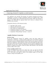
Application <strong>Note</strong> #<strong>1453</strong><br />
Description of the ICM-19540 Breakout Module<br />
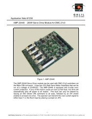
The ICM-19540 is a breakout module that attaches to the AMP-19540 for easy screw<br />
terminal connections to the signals coming from the Aux IO and axis D-sub connectors.<br />
The pin-out for the screw terminals can be seen in Fig. 1 below.<br />
Fig. 1– Image of ICM-19540 screw terminals with labeling<br />
Pinout<br />
Aux I/O<br />
01 PWM/MCMD Z 23 W Latch/Input 4<br />
02 Output 6 24 X Latch/Input 1<br />
03 Output 8 25 PWM/MCMD X<br />
04 Output 5 26 X Home<br />
05 Output 2 27 Y Home<br />
06 Abort (see Appendix A) 28 Z Home<br />
07 Input 6 29 W Home<br />
08 Z Latch/Input 3 30 Error Out<br />
09 SIGN/AEN Y 31 PWM/MCMD W<br />
10 Output Compare 32 5V<br />
11 Reverse Limit X 33 5V<br />
12 Reverse Limit Y 34 Ground<br />
13 Reverse Limit Z 35 Ground<br />
14 Reverse Limit W 36 Input 8<br />
15 Forward Limit W 37 Input 5<br />
- 1 -<br />
<strong>Galil</strong> Motion Control, Inc. • 270 Technology Way • Rocklin, CA 95765 USA • 800-377-6329 • Ph: 916-626-0101 • Fax: 916-626-0102 • www.galilmc.com
16 SIGN/AEN W 38 Y Latch/Input 2<br />
17 SIGN/AEN Z 39 PWM/MCMD Y<br />
18 Output 7 40 SIGN/AENX<br />
19 Output 4 41 Forward Limit X<br />
20 Output 1 42 Forward Limit Y<br />
21 Output 3 43 Forward Limit Z<br />
22 Input 7 44 Reset<br />
X Axis Y Axis<br />
01 I+ X 01 I+ Y<br />
02 B+ X 02 B+ Y<br />
03 A+ X 03 A+ Y<br />
04 AB+ X 04 AB+ Y<br />
05 GND 05 GND<br />
06 I- X 06 I- Y<br />
07 B- X 07 B- Y<br />
08 A- X 08 A- Y<br />
09 AA- X 09 AA- Y<br />
10 Hall X A 10 Hall Y A<br />
11 AA+ X 11 AA+ Y<br />
12 AB- X 12 AB- Y<br />
13 Hall X B 13 Hall Y B<br />
14 Hall X C 14 Hall Y C<br />
15 5V 15 5V<br />
Z Axis W Axis<br />
01 I+ Z 01 I+ W<br />
02 B+ Z 02 B+ W<br />
03 A+ Z 03 A+ W<br />
04 AB+ Z 04 AB+ W<br />
05 GND 05 GND<br />
06 I- Z 06 I- W<br />
07 B- Z 07 B- W<br />
08 A- Z 08 A- W<br />
09 AA- Z 09 AA- W<br />
10 Hall Z A 10 Hall W A<br />
11 AA+ Z 11 AA+ W<br />
12 AB- Z 12 AB- W<br />
13 Hall Z B 13 Hall W B<br />
14 Hall Z C 14 Hall W C<br />
15 5V 15 5V<br />
- 2 -<br />
<strong>Galil</strong> Motion Control, Inc. • 270 Technology Way • Rocklin, CA 95765 USA • 800-377-6329 • Ph: 916-626-0101 • Fax: 916-626-0102 • www.galilmc.com
External Amplifiers or Drives<br />
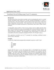
If an external drive or amplifier is to be used with the AMP-19540 and ICM-19540, the<br />
motor command and enable signals must be configured. This is accomplished by placing<br />
jumpers across the appropriate pins at locations X, Y, Z, and W on the AMP-195x0, near<br />
the J1 connector. See figure 3.<br />
Fig 3. External Drive: Configuring the Proper Amplifier Signals to the ICM<br />
There are two rows of three pins per axis. Install the jumpers on the MCM and AEN side<br />
of each row if the axis drives an external servo amplifier (other than the AMP-19520/40).<br />
That axis’s PWM and SGN digital outputs will be inaccessible.<br />
Install the jumpers on the PWM and SGN side of each row of pins if the axis drives an<br />
external stepper drive (or external PWM-input servo amplifier). That axis’s MCM and<br />
AEN outputs will be inaccessible. Additionally, the SM jumper(s) must be installed on<br />
the controller for those axes configured for PWM output.<br />
- 3 -<br />
<strong>Galil</strong> Motion Control, Inc. • 270 Technology Way • Rocklin, CA 95765 USA • 800-377-6329 • Ph: 916-626-0101 • Fax: 916-626-0102 • www.galilmc.com
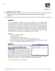
External Amplifiers or Drives: Jumper Details<br />
MCM<br />
AEN<br />
Setting for analog motor command output<br />
- 4 -<br />
Setting for step/direction output<br />
PWM<br />
SGN<br />
MCM<br />
This jumper across MCM & J3.xx brings that axis’s Motor Command analog output to<br />
the J3.xx screw terminal location.<br />
AEN<br />
This jumper across AEN & J3.xx brings that axis’s Amplifier Enable digital output to the<br />
J3.xx screw terminal location.<br />
PWM<br />
This jumper across PWM & J3.xx brings that axis’s Pulse Width Modulation digital<br />
output to the J3.xx screw terminal location.<br />
SGN<br />
This jumper across SGN & J3.xx brings that axis’s Sign(direction) digital output to the<br />
J3.xx screw terminal location.<br />
<strong>Galil</strong> Motion Control, Inc. • 270 Technology Way • Rocklin, CA 95765 USA • 800-377-6329 • Ph: 916-626-0101 • Fax: 916-626-0102 • www.galilmc.com