preprint - Gatsby Computational Neuroscience Unit - UCL
preprint - Gatsby Computational Neuroscience Unit - UCL
preprint - Gatsby Computational Neuroscience Unit - UCL

You also want an ePaper? Increase the reach of your titles
YUMPU automatically turns print PDFs into web optimized ePapers that Google loves.
Rapid Convergence to Feature Layer<br />
Correspondences<br />
Jörg Lücke 1 , Christian Keck 2 , and Christoph von der Malsburg 3<br />
1 <strong>Gatsby</strong> <strong>Computational</strong> <strong>Neuroscience</strong> <strong>Unit</strong>, <strong>UCL</strong><br />
London WC1N 3AR, UK<br />
2 Institut für Neuroinformatik, Ruhr-Universität Bochum<br />
44780 Bochum, Germany<br />
3 Frankfurt Institute for Advanced Studies, Goethe-Universität Frankfurt<br />
60438 Frankfurt am Main, Germany<br />
Abstract<br />
We describe a neural network able to rapidly establish correspondence between<br />
neural feature layers. Each of the network’s two layers consists of interconnected<br />
cortical columns and each column consists of inhibitorily coupled subpopulations<br />
of excitatory neurons. The dynamics of the system builds upon<br />
a dynamic model of a single column, which is consistent with recent experimental<br />
findings. The network realizes dynamic links between its layers with<br />
the help of specialized columns that evaluate similarities between the activity<br />
distributions of local feature cell populations, are subject to a topology constraint,<br />
and can gate the transfer of feature information between the neural layers.<br />
The system can robustly be applied to natural images and correspondences<br />
are found in time intervals estimated to be smaller than 100 ms in physiological<br />
terms.<br />
Keywords: Cortical Columns, Homomorphy, Non-linear Dynamics, Correspondence<br />
Problem, Visual Cortex, Dynamic Links<br />
1 Introduction<br />
Neural Computation, in press, 2008<br />
Aristotle described two kinds of mental association: by time and by pattern (The<br />
Complete Works of Aristotle, Barnes (ed.), 1984). It is interesting to note that standard<br />
neural network theory, which sees association by time implemented as Hebbian<br />
plasticity, has no sophisticated and direct concept of association by pattern. In standard<br />
approaches, a common way to link two patterns is to compactly represent them<br />
by cardinal cells, which can then be associated by time, but only if external events<br />
activate the patterns simultaneously. Thus, structural relations between patterns as<br />
such cannot lead to association directly.<br />
1
A mechanism that enables association by pattern requires a concept of pattern<br />
similarity and, for complex patterns, similarity is best formulated as homomorphy:<br />
A pattern is composed of elements that carry feature labels and that have neighborhood<br />
relationships. Two patterns are homomorphic if there is a mapping between<br />
them that relates elements with similar labels such that neighbors are mapped onto<br />
neighbors. The process of establishing such a mapping is often referred to as matching.<br />
In the context of vision, homomorphic pattern matching is important to find<br />
stereo correspondences (i.e. finding point-to-point relationships between the two<br />
retinal images), for motion extraction (finding correspondences between consecutive<br />
images), and for pattern recognition (finding correspondences between retinal<br />
images and patterns in memory). Systems that apply explicit pattern matching mechanisms<br />
are state-of-the-art in object and face recognition technology (Philips et al.,<br />
2000; Messer et al., 2004). More generally, pattern associations are probably fundamental<br />
for subsystem integration in the brain and for intelligence in general, where<br />
new problems are solved by homomorphy to known problems or to abstract schemas.<br />
It has repeatedly been proposed to expand standard neural networks by the introduction<br />
of a class of neural units that stand not for pattern elements but that stand for<br />
relationships between pattern elements. The general idea is formulated in (Kree and<br />
Zippelius, 1988), application to stereo matching in (Dev, 1975; Marr and Poggio,<br />
1976), and application to correspondence-based object recognition, e.g., in (Hinton,<br />
1981; Olshausen et al., 1993; Wiskott and von der Malsburg, 1995; Arathorn, 2002;<br />
Zhu and von der Malsburg, 2004). These systems are non-standard in requiring unusual<br />
interaction patterns to implement estimation of label similarity, topographic<br />
relations and for controlling the flow of signals between the matched patterns.<br />
The model we present here builds on previous neural network approaches such<br />
as (Hinton, 1981; Olshausen et al., 1993; Wiskott and von der Malsburg, 1995).<br />
The model described in (Hinton, 1981) represents an early conceptual study. The<br />
model in (Olshausen et al., 1993) represents an analytically and numerically wellinvestigated<br />
correspondence-based approach that is, however, limited to scalar features<br />
types and artificial input. The model in (Wiskott and von der Malsburg, 1995)<br />
uses more advanced features and realistic input but has problems to neurally explain<br />
feature similarity evaluation and it cannot account for the speed of human object<br />
recognition as measured by Thorpe et al. (1996).<br />
The neural network model studied in this work addresses these deficits of previous<br />
models. We use a neural dynamic approach that reflects recent results on<br />
cortical connectivity (e.g. Douglas and Martin, 2004; Yoshimura et al., 2005) and<br />
implements pattern matching using neural populations as elementary computational<br />
units. We find that the network model can (1) establish pattern correspondences in<br />
physiologically plausible times (
model of a single cortical column as formulated in (Lücke, 2005), and subsequently<br />
introduce the architecture of our network model which consists of two layers of<br />
such columns. The dynamics of the layers and their principle interaction is defined<br />
and discussed in Sec. 3. Sec. 4 describes how feature arrangements are neurally<br />
evaluated and Sec. 5 gives details of the Gabor-features used. In Sec. 6, numerical<br />
simulations show the system’s dynamic behavior and its convergence to pattern<br />
correspondences if natural images are used as input. Sec. 7 discusses the system’s<br />
properties and its relation to the literature.<br />
2 Columnar Network Model<br />
The central element of our model is the cortical column. Depending on the perspective<br />
or the cortical area a column is also often referred to as macrocolumn (Mountcastle,<br />
1997), segregate (Favorov and Diamond, 1990), or hypercolumn (Hubel and<br />
Wiesel, 1977) and in primary visual cortex comprises roughly all neurons that can<br />
be activated from one point in visual space. In recent neurophysiological experiments<br />
it was shown that columns possess a fine-structure of relatively disjunct subpopulations<br />
of excitatory neurons (Yoshimura et al., 2005). A model of a column<br />
with this structure was studied in (Lücke and von der Malsburg, 2004; Lücke, 2004)<br />
and we will base our system on an abstract dynamical formulation as suggested in<br />
(Lücke, 2005). This abstract formulation models the mean activity in populations of<br />
f(p, h)<br />
2<br />
0<br />
−2<br />
−4<br />
h = 0.2<br />
h = 0.25<br />
h = 0.3<br />
0 0.2 0.4 0.6<br />
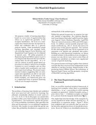
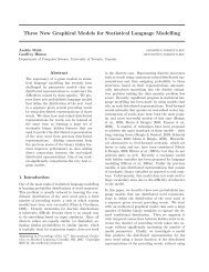
Figure 1: Plot of the function f(p,h) in (1) for three different values of h with<br />
σn = 0. The function models the behavior that is expected from a population of in-<br />
terconnected excitatory neurons with inhibitory input h. If d<br />
dt<br />
p<br />
p = f(p,h) describes<br />
the change of activity p in such a population than f results in two stable stationary<br />
points if h is small: one at zero and one with high activity. The activity is increased<br />
if f(p,h) > 0 and decreased if f(p,h) < 0. Values are plotted for a = 100 (unit<br />
omitted) but note that just the scale of the y-axis changes for other values of a.<br />
excitatory neurons. To recapitulate the approach in (Lücke, 2005), consider a single<br />
population of excitatorily interconnected neurons. Through its connections, such a<br />
3
population can be expected to increase its activity level. From a critical level of activity<br />
on, active neurons in one time interval can excite an increasingly large number<br />
of neurons in the next time interval. This positive feed-back loop continues until the<br />
self-excitation is counterbalanced by self-inhibition, e.g., through neural refraction<br />
times. If activity in the population is very low, excitatory neurons are not able to excite<br />
a larger number of other neurons. In this case we expect the activity to decay to<br />
zero. If the change in activity is described by a differential equation d<br />
dt<br />
p = f(p,h)<br />
with p denoting the population’s mean activity, we can model this expected dynamic<br />
behavior using a polynomial of order three for f:<br />
f(p,h) = a (p 2 − h p − p 3 ) + σnηt . (1)<br />
In (1), σnηt is additive Gaussian noise of variance σ 2 n, which models noisy activities<br />
that are to be expected. The linear term −hp models the influence of external<br />
inhibition h: the effect of inhibition increases the more neurons are active, for no<br />
activity inhibition is without effect. Fig. 1 depicts the function f for three different<br />
values of h and no noise. As can be observed, a population can only stabilize high<br />
levels of activity if the level of inhibition is small. For high levels, the population<br />
activity converges to zero.<br />
The column model used in this paper consists of k populations of excitatory neurons<br />
that are coupled inhibitorily. Measurements reported in (Yoshimura et al., 2005)<br />
suggest that such a model reflects the fine-scale structure within a cortical column.<br />
Pyramidal cells in layer 2/3 of the visual cortex were found to form functionally<br />
disjunct populations that receive a common inhibition from within their layer. Here,<br />
we will model this lateral inhibition to be proportional to the maximally active population<br />
in the column: h = h(p1,...,pk) = ν maxα{pα}, where pα denotes the<br />
activity in population or unit α of the column. Different types of inhibitory coupling<br />
were studied (see, e.g., Lücke et al., 2002; Lücke and von der Malsburg, 2004) but<br />
inhibition proportional to the maximal activity has been found to have a number of<br />
functional advantages (Lücke, 2005). Taken together, the dynamics of a column is<br />
described by the equation system:<br />
d<br />
dt pα = f(pα,ν max<br />
β=1,...,k {pβ}) + κ ˜ Jα , (2)<br />
where the ˜<br />
Jα’s are external inputs to the α = 1,...,k different units. κ parameterizes<br />
the coupling strength of the column dynamics to the input. As a neuron<br />
within a population is found to receive most of its input from within its own population<br />
(Yoshimura et al., 2005), κ will later (Sec. 6) be set to a value which is small<br />
compared to a in (1).<br />
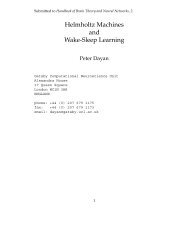
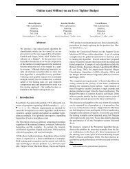
In this paper a multitude of columns of the type above constitute neural layers for<br />
the representation of input and model images. A simple model setting for the process<br />
of correspondence finding (see Fig. 2A) consists of an input layer I, left array of<br />
large shaded ellipses, and a model layer M, right array. Both layers represent images<br />
by activity distributions in local feature-sensitive populations and will therefore be<br />
referred to as feature layers. The model domain should contain many such feature<br />
4
layers to represent objects in memory, but in this work we focus on just one. Note<br />
that for visualization purposes the layers in Fig. 2A are displayed one-dimensionally.<br />
In each point of the two layers there are two columns, one to represent local features<br />
(horizontal ellipses within the shaded regions of Fig. 2A) and one (vertical ellipse) to<br />
control the connections or links between the two layers. This double column (shaded<br />
ellipse in Fig. 2A) is called a node. Feature columns represent, with their activity,<br />
the local textures of the input or model images. Different activity levels in their<br />
units encode for different local spatial frequencies and orientations of an image’s<br />
gray-level distribution, details of which will be given later in Sec. 5.<br />
As will be discussed at the end of the paper, the feature layers can be thought<br />
of as different areas in the visual cortex. They communicate through links, which<br />
connect feature columns by as many fibers as there are feature types. In a link<br />
control column each unit stands for one link entering the node and does three things.<br />
One, it compares the activity distributions of the feature columns at the two ends<br />
of the link, two, it tries to be consistent with activities of units controlling parallel<br />
links (“topology constraint”), and three, by its activity it keeps open its link. The<br />
situation is shown in more detail in Fig. 3A. As we will see later, the dynamics of<br />
the system results, per column, in the deactivation of all but one control unit, i.e.,<br />
all but one of the links into a node are switched off. The link that remains active<br />
is selected by a combination of two criteria. One is feature similarity, the other is<br />
the topology constraint. The latter is to favor those link arrangements that connect<br />
neighbors in one layer with neighbors in the other layer, and is implemented by<br />
connections between control units in neighboring nodes (see Fig. 2B). The topology<br />
constraint is important when feature similarities are ambiguous and would, on their<br />
own, lead to many wrong correspondences. For a systematic study of the influence<br />
of the topological constraint see (Wiskott, 1999).<br />
3 System Dynamics<br />
The dynamics of the system builds upon the column model given by (2). The dynamic<br />
properties of single columns and the specific connectivity outlined in the previous<br />
section define the dynamic properties of the whole network. We first introduce<br />
some notation. Let L ∈ {I, M} and L ′ ∈ {I, M}\{L} be indices for the two lay-<br />
ers, i.e., (L, L ′ ) = (I, M) or (M, I). Further, let p Li<br />
α stand for the activity of the<br />
feature unit α in node i of layer L (Fig. 3B). We assume α to run from 1 to k and i<br />
from 1 to N, where N is the number of nodes per layer. Using the column model<br />
(2), the dynamics of the feature columns is described by<br />
d<br />
dt pLi<br />
α = f(p Li<br />
α ,ν max<br />
β=1,...,k {pLi<br />
β }) + κ ˜ J Li<br />
α , (3)<br />
where ˜ J Li<br />
α is feature input to the unit α of node Li. A feature column represents<br />
a given feature vector ( ˜ J Li<br />
1 ,..., ˜ J Li<br />
k ) by activities of its k sub-populations. The<br />
feature vectors can convey information from the other layer and from an (input or<br />
model) image. The importance of input from the other layer lies in the transmission<br />
5
node M1<br />
feature column<br />
A B<br />
J I1<br />
J I2<br />
J I3<br />
p I2<br />
3<br />
W I3,M3<br />
control column<br />
W M2,I3<br />
J M1<br />
control column connections<br />
J M2<br />
J M3<br />
column W M1<br />
Figure 2: A Network of columns for correspondence finding. The network consists<br />
of an input layer and a model layer with nodes I1 to I3 and M1 to M3, respectively.<br />
Each node consists of a feature column (horizontal ellipse) with k = 4 units and of<br />
a control column (vertical ellipse) with N = 3 units. Each node in the input layer<br />
receives input from each node in the model layer, and vice versa. The inputs to<br />
a node are modulated by its control column according to the interconnectivity as<br />
displayed in Fig. 3. The control columns receive input from the units of feature<br />
columns of both layers and from neighboring control columns. B Input received<br />
by control column W M2 . <strong>Unit</strong>s that control parallel links excite each other. The<br />
interconnectivity implements cyclic boundary conditions.<br />
6<br />
T
B<br />
J I1<br />
J I2<br />
J I3<br />
link (Mi, I2)<br />
link (Mi, I3)<br />
p I2<br />
3<br />
link (Mi, I1)<br />
feature units<br />
A<br />
W Mi,I1<br />
W Mi,I2<br />
W Mi,I3<br />
control column W Mi<br />
feature column p I3<br />
J I1<br />
J I2<br />
J I3<br />
feature columns<br />
p Mi<br />
4<br />
J Mi<br />
link<br />
control units<br />
link control<br />
feature input<br />
connection between<br />
control columns<br />
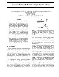
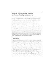
Figure 3: Detailed connectivity of one model node. The node Mi consists of a<br />
feature column and a control column. On the input side, only the feature columns of<br />
the input nodes are shown. The feature vectors J Ij (on the input side) and J Mi (on<br />
the model side) are represented by the activity distributions in their feature columns.<br />
Images A and B illustrate the connectivity of the model node at different resolutions.<br />
In A the information that converges onto the node’s control column is shown together<br />
with the controlled links. Input to each control unit is a mixture of, one, feature<br />
inputs from different layers and, two, inputs from neighboring control columns of<br />
the same layer. For details about the connections that convey the latter type of input<br />
see Fig. 4. The control column has as many units as there are nodes in the input layer,<br />
in order to control as many links. A given control unit integrates feature information<br />
from the pair of feature columns that is associated with its link and from neighboring<br />
control columns. In B the connectivity of the model node is shown in more detail and<br />
together with labels for the system’s dynamic variables as they appear in (3) to (5).<br />
Connections from other control columns are not shown. The control units evaluate<br />
the similarity between feature column activities in terms of the scalar product of<br />
their activity vectors (multiplicative interactions indicated by arrowheads touching<br />
connecting fibers). With its output a control unit gates the incoming link it stands<br />
for. Linking fibers are depicted as feature preserving. The small circle represents<br />
neurons that, by inhibition, subtract the mean from incoming feature inputs.<br />
7<br />
J Mi
of information after correspondences have been established. In that situation the<br />
information is channeled through the links between the layers that connect corresponding<br />
points, and it is the task of the control columns to select these links. In this<br />
paper we study the neural dynamics of link selection, for which the direct connections<br />
between feature columns are not required. For simplicity, the inputs in (3) will<br />
therefore convey information from the (input or model) image alone (see Lücke and<br />
von der Malsburg, 2006, for a system with about an equal mixture of image input<br />
and input from the other layer). Details of the image features will be given in Sec. 5.<br />
For the control columns we use the same dynamic model as for the feature<br />
columns. To allow for potentially all possible connection patterns between the layers,<br />
each control column must contain as many control units as there are nodes in the<br />
other layer, in order to control as many links (see Fig. 2A and Fig. 3A). The control<br />
column of node Li will be referred to as W Li and the activity in its units will be<br />
denoted by W Li,L′ j with j = 1,...,N (see Fig. 3B). A unit W Li,L ′ j controls the<br />
link from node L ′ j in layer L ′ to node Li in layer L. The link is open or active if<br />
and only if its unit is active. The activity distribution within a control column, W Li ,<br />
represents the current connectivity of node Li to nodes of the other layer. The distribution<br />
is determined by the dynamics within the control column and by its inputs<br />
I Li,L′ j :<br />
d<br />
dt W Li,L′ j = f(W Li,L ′ j ,ν max<br />
l=1,...,N {W Li,L′ l }) + κ I Li,L ′ j , (4)<br />
I Li,L′ j<br />
= CI<br />
k<br />
p<br />
α,β=1<br />
Li<br />
α R Li,L′ j<br />
αβ p L′ j<br />
β + (1 − CI) T<br />
<br />
similarity term<br />
Li,L′ j<br />
, (5)<br />
<br />
topology term<br />
where CI ∈ [0, 1] controls the relative influence of the two terms in (5). The first<br />
term evaluates feature information represented by feature columns pLi and pL′ j ,<br />
which is conveyed by the afferents (R Li,L′ j<br />
αβ ) to control unit W Li,L′ j . We use for<br />
all control units the same connectivity structure and choose R Li,L′ j<br />
αβ = δαβ − 1.<br />
In k<br />
this case the similarity term resembles a scalar product with Euclidean metric between<br />
the activity vectors of the two associated feature columns p Li and p L′ j (other<br />
choices of R Li,L′ j<br />
αβ would correspond to other metrics). The second term in (5) implements<br />
the interaction between control columns within a layer, which will be used<br />
to enforce the topological constraint (Sec. 4). The connectivity of a single control<br />
column is illustrated in Fig. 3.<br />
If equations (3) and (4) are numerically simulated, we find that the dynamics<br />
possesses, for a wide range of parameters, a number of point attractors that grows<br />
exponentially with the number of units in the system. That is, the system can stabilize<br />
any subset of active units in any column (feature or control column). The<br />
system inherits this property from the single column model (2) which can be shown<br />
to possess up to (2k − 1) stable stationary points (if k is the number of units in the<br />
column). The network state with maximal activity is the state in which all units in<br />
all columns are active. Stability in the network crucially depends on the level of inhibition<br />
within the individual columns, and this level is controlled by the parameter<br />
8
ν in (3) and (4). If ν is increased, the number of stable stationary points decreases.<br />
The transitions of the stable states to unstable states occur around ν = 0.5 which is<br />
the bifurcation point of the single column model (2) in the case of no input 1 .<br />
If ν in dynamics (3) and (4) gets larger, only activity configurations can survive<br />
in which active units sufficiently excite each other through their mutual connections.<br />
The dynamics thus selects the most stable subnets of active units from a large class<br />
of possible ones. The stability of these subnets is hereby determined by the internal<br />
connectivity of the network and by external feature input. In our system the internal<br />
connectivity allows for a comparison of activity distributions in feature columns<br />
(similarity term) and for an interaction between control columns that will be used<br />
to favor particular activation patterns (topology term). For low levels of inhibition,<br />
the system can potentially stabilize all activity configurations and we start with the<br />
state of maximal activity to allow for the selection of potentially any of them. Under<br />
the influence of noise, the state of maximal activity is, during an initial phase,<br />
automatically stabilized using zero inhibition (ν = 0). Subsequently, we increase ν<br />
from a value νmin = 0.4 that is smaller than the critical value of νc = 0.5 to a value<br />
νmax = 0.6 that is larger:<br />
ν(t) =<br />
0 if ˜t < Tinit<br />
(νmax − νmin) ˜t−Tinit<br />
T −Tinit + νmin if ˜t ≥ Tinit<br />
, (6)<br />
where ˜t = t mod T , which is t − nT , with n the greatest integer satisfying<br />
t − nT ≥ 0. That is, after ν has reached its maximal value, the system is reset<br />
to full activity at ν = 0 again, and the selection process can begin anew. Such a<br />
cyclically driven ν allows for a repeated selections as required for changing inputs<br />
in realistic situations. One selection cycle, consisting of a reset to full activity and<br />
an increase of ν from νmin to νmax, will be called a ν-cycle (see Lücke and von der<br />
Malsburg, 2004).<br />
4 Implementations of the Topology Constraint<br />
To understand the effect of the topological term let us consider one-dimensional<br />
layers first. The connectivity among control columns is displayed in Fig. 4A for the<br />
case of layers with five instead of three nodes as in Fig. 2B. For simplicity we have<br />
chosen to just connect units that control strictly parallel links. Such a connectivity<br />
is reflected by the following form of the topology term in (5):<br />
T Li,L′ j =<br />
A<br />
a=−A<br />
Ta ˜ W Li+a,L′ j+a with (Ta) = (...,u2, u1, 0, u1, u2,...), (7)<br />
where Ta is a one-dimensional kernel with ui denoting positive connectivity strengths.<br />
˜W Li,L′ j is the mean-free version of control column activity W Li,L′ j given by<br />
˜W Li,L′ j Li,L = W ′ j 1 <br />
− N l W Li,L′ l . The sum over a is taken to continue cyclically<br />
1 For ν = 0.5 + ǫ the activities pα possess stable states at pα = 0.5 + ǫ which results in a value of<br />
h = 0.25 + ǫ (compare Fig. 1).<br />
9
if the index (i + a) or (j + a) exceeds the index range (compare Fig. 2B), i.e., the<br />
neighborhood relationship between control columns has the topological structure of<br />
a ring. Note that for Fig. 2B the maximal distance between connected columns, A,<br />
equals 1, and equals 2 in Fig. 4A. The connectivity given by (7) establishes mutual<br />
excitation between control units of parallel links. The situation is displayed in<br />
Fig. 5E for columns connected as in Fig. 4A. If a given control unit is active, it helps<br />
to keep active parallel links of its neighbors. Together with local inhibition within<br />
the control columns, this implements a competition between connectivity structures<br />
of parallel links. If the parameter ν is small enough, all these connectivity structures<br />
can co-exist. But if ν is increased, control units of structures which are only weakly<br />
supported by feature similarities are deactivated.<br />
Fig. 4B illustrates connectivity that implements the topological constraint for<br />
two-dimensional layers. Only the connections for the central unit of the central<br />
column are shown. Note that for two-dimensions, the indices i and j in Eqns. (3)<br />
to (5) become two-dimensional (i → i and j → j). The topology term in (5) now<br />
reads:<br />
T Li,L ′j =<br />
(A,A)<br />
<br />
a=(−A,−A)<br />
Ta ˜ Li+a,L ′j+a<br />
W<br />
with (Ta) =<br />
⎛<br />
⎜<br />
⎝<br />
.<br />
u2<br />
u1<br />
· · · u2 u1 0 u1 u2 · · ·<br />
u1<br />
u2<br />
.<br />
⎞<br />
(8)<br />
⎟ ,<br />
⎟<br />
⎠<br />
where (Ta) is a two-dimensional kernel (empty entries are zero) in which the ui<br />
denote positive connectivity strengths (compare Eqn. 12). For a given control unit<br />
W Li,L ′j , the matrix (Ta) contains the weights of all afferents from control units<br />
of neighboring parallel links. Fig. 4B illustrates the two-dimensional connectivity<br />
given by (8) for A = 2. In this case the potentially (2A + 1) 2 = 25 neighbors could<br />
be connected. However, for the kernel in (8) just the eight neighbors that correspond<br />
to the eight non-zero entries of (Ta) are connected (black arrows in Fig. 4B) 2 .<br />
We have also tested a version of the system which includes diagonal connectivity<br />
between neighboring columns (corresponding to non-zero entries on the diagonals<br />
of Ta), but have not observed significant functional advantages. We have therefore<br />
chosen to work with the kernel as described above as numerical simulations can be<br />
made more efficient in this case. Similarly to diagonal connections, a connectivity<br />
that involves connections between approximately parallel fibers has not produced<br />
significant functional improvements for the sets of natural images considered here<br />
(see below). In a system with one-dimensional layers as described in (Lücke and<br />
von der Malsburg, 2006), also approximately parallel links are interacting. There,<br />
feature vectors were artificial and independent from node to node. In the system<br />
2 Again we assume cyclic boundary conditions in the layers, such that the neighborhood relationship<br />
amongst the nodes in a layer now has the topological structure of a torus.<br />
10
W i,j<br />
u2<br />
u1<br />
A<br />
W i+a,j+a<br />
u1<br />
-2<br />
u2<br />
-1<br />
0<br />
W i<br />
1<br />
W i+a<br />
2<br />
a2<br />
-2<br />
u2<br />
-1<br />
W i<br />
u1<br />
u2<br />
B<br />
u1<br />
0 1 2<br />
u1<br />
u2<br />
u1<br />
W i,j<br />
u2<br />
a1<br />
W i+a,j+a<br />
W i+a<br />
Figure 4: A Connectivity of control columns for one-dimensional input and model<br />
layers with five nodes each. All inputs received by the central unit of the central<br />
column are shown. Only units that control exactly parallel links are connected.<br />
Connectivity of any other unit is obtained by globally shifting the displayed connections<br />
while respecting cyclic boundary conditions (compare Fig. 2B). Note that in A<br />
and B the prefixes L and L ′ have been suppressed. W i denotes the control column<br />
of node i and W i,j denotes its control unit with index j. The connectivity associated<br />
with the non-zero entries ui of the kernel (Ta) in (7) is shown (black arrows).<br />
B Connectivity of control columns for two-dimensional input and model layers with<br />
5 × 5 nodes each. In B, i and j become vectorsi and j. All inputs received by the<br />
central control unit of the central column are shown. Again, the connectivities of<br />
any other unit can be obtained by globally shifting the displayed connections while<br />
respecting cyclic boundary conditions. Only units controlling exactly parallel links<br />
are connected. The connectivity associated with the non-zero entries ui of the kernel<br />
(Ta) in (8) is shown (black arrows).<br />
11
described here we will use Gabor-wavelet filters as basis for our feature vectors.<br />
Consequently, neighboring feature vectors and the activity in their feature columns<br />
will not be independent. Control units of parallel links will be correlated also in the<br />
case in which only exactly parallel links are connected.<br />
5 Feature Vectors<br />
Let us neglect color and binocularity of the input and let the sub-populations of a<br />
column just be sensitive to different spatial frequencies and orientations, describing<br />
their receptive fields (RFs) by the well-known Gabor wavelets. Gabor wavelets describe<br />
the response properties of neurons in primary visual cortex (Jones and Palmer,<br />
1987; Ringach, 2002) and are thought to be the basic constituents of natural images.<br />
They can be learned by a variety of algorithms, including ICA (Bell and Sejnowski,<br />
1997) and sparse coding (Olshausen and Field, 1996). Note that Gabor-wavelets,<br />
indeed, also emerge if a system based on the dynamical column model as used in<br />
this paper is applied to natural images (Lücke, 2007). However, instead of learning<br />
them, we use a predefined set of Gabor wavelets for our purposes. To model the<br />
RFs of the sub-populations of our feature columns, we use Gabor filter responses as<br />
inputs. If V is an image with V (x) denoting the gray-value of a pixel at position x,<br />
the filter responses Qα (x) are given by:<br />
Qα (x) =<br />
ψα (x) = k2 α<br />
σ 2 exp<br />
<br />
V (x ′ )ψα(x − x ′ )d 2 x ′ , (9)<br />
<br />
<br />
exp <br />
ikαx <br />
− exp <br />
−σ2 <br />
, σ = 2π , (10)<br />
2<br />
− k2 αx 2<br />
2σ 2<br />
where the wave vector is parameterized as<br />
kα =<br />
<br />
kαx<br />
kαy<br />
<br />
=<br />
<br />
kρ cos ϕµ<br />
kρ sin ϕµ<br />
<br />
ρ+2<br />
(− , kρ = 2 2 ) π, ϕµ = µ π<br />
8<br />
, (11)<br />
with ρ = 1,.., 5 and µ = 1,.., 8. That is, (Q1(x),...,Q40(x)) is a vector of Gaborfilter<br />
responses in which each entry corresponds to one of the 40 combinations of<br />
ρ and µ. As feature values we use the magnitude J Li<br />
α = |Qα(xi )|, thus ignoring<br />
Gabor phase to model complex cell responses (Hubel and Wiesel, 1977) (while appropriately<br />
sampling the spatial layer, with xi denoting the image position of node<br />
Li). As input to a feature column, (3), we use the mean-free version of J Li<br />
α given<br />
by ˜ J Li<br />
α = J Li<br />
α − 1 kβ=1 J k<br />
Li<br />
β with k = 40. Feature vectors as defined by (9) to<br />
(11) have been used in various systems including Dynamic Link Matching (DLM)<br />
(Wiskott and von der Malsburg, 1995) and highly competitive applications to face<br />
and object recognition (e.g. Okada et al., 1998). For the formulation used here see<br />
(Wiskott et al., 1995). In applications using Gabor-features it has turned out that<br />
with 40, as above, good results can be achieved. Performance increases for more<br />
wavelets, but 40 represents a good compromise between performance and computational<br />
cost.<br />
12
6 Simulations<br />
To demonstrate the functioning of the system we use natural images of 512 × 512<br />
pixels. Each input and each model image is covered by a grid of 8 × 8 nodes with<br />
cyclic boundary conditions (see Fig. 5A-D right images). Control columns are taken<br />
to be connected according to (8) with A = 3 and ui given by:<br />
<br />
ui = exp − 1<br />
2 i<br />
2 A<br />
<br />
. (12)<br />
The exact values of the ui’s are of subordinate importance for the simulation results<br />
but, in general, they should lie between 0 and 1 and should decrease with increasing<br />
i.<br />
We numerically simulate the differential equations (3) and (4) with time steps<br />
of ∆t = 1 ms. The time constant a in (1) for the columnar dynamics (3) and (4)<br />
50<br />
reflects the ability of the balanced network to rapidly stabilize new balanced states.<br />
In an earlier system with explicitly modeled spiking neurons (Lücke and von der<br />
Malsburg, 2004) the input sensitive transition from fully active columns to states<br />
with just one active unit was possible within a ν-cycle of T = 25 ms. For the<br />
abstract dynamics (3) and (4) with (1) this behavior is reproduced for time constants<br />
of roughly a = 100 ms−1 (compare Lücke and Bouecke, 2005) and same T (to reset<br />
the system we found that time intervals of about Tinit = 4 ms are sufficient). We<br />
choose the noise term in (1) to be relatively small, σn = 1 × 10⁻⁷ ms−1 , and the<br />
input is taken to just weakly couple to the column dynamics κ = 1.0 ms−1 (κ ≪ a)<br />
as in (Lücke and von der Malsburg, 2004), (Lücke, 2004) and (Lücke and Bouecke,<br />
2005).<br />
Input to a feature column potentially consists of feature vector input from its own<br />
layer and of input from feature columns of the other layer. After correspondences<br />
have been found, the direct connections between feature columns are crucial to convey<br />
image information between the layers in order to recognize or classify objects in<br />
later stages of processing (compare Olshausen et al., 1993). Fig. 3B illustrates how<br />
feature information can be transfered from one to the other layer. For the task of correspondence<br />
finding, as considered here, a direct exchange of information between<br />
feature columns is, however, not required. For simplicity, the feature layers thus<br />
solely communicate via their systems of control columns in the dynamics studied<br />
here. In a more general system, input to feature columns (see Eqn. 3) can, however,<br />
also constitute of mixtures of feature vector input and feature column input from the<br />
other layer (compare Lücke and von der Malsburg, 2006).<br />
The system of control columns integrates feature information and information<br />
about the connectivity state between the layers. That is, control columns receive<br />
input from the evaluation of feature similarities between the layers and from neighboring<br />
control columns. Both input sources we take to be mixed using CI = 0.25 in<br />
(5), i.e., the topology term is emphasized more than the similarity term.<br />
For our simulations we visualize the activities of the control columns, i.e., the<br />
dynamic variables W Mi,Ij Ii,Mj Mi,Ij Ii,Mj<br />
and W in (4). The matrices W and W<br />
represent the connectivity from input layer I to model layer M and from M to<br />
13
I, respectively. For one-dimensional layers the matrices W are two-dimensional<br />
and their visualization allows a direct interpretation of the inter-layer connectivity<br />
(compare Zhu and von der Malsburg, 2004; Lücke and von der Malsburg, 2006) 3 .<br />
For two-dimensional input, W Mi,Ij and W Ii,Mj are four-dimensional matrices<br />
and, although their entries can in principle be visualized, the connectivities they<br />
represent are difficult to grasp intuitively. For two-dimensional images it is more<br />
instructive to visualize, for each control column, the center of gravity of its activity<br />
distribution. That is, we compute the position y Li using:<br />
y Li =<br />
<br />
j W Li,L ′j<br />
xL ′j<br />
, (13)<br />
j<br />
W Li,L ′j<br />
where the index j runs over all 64 nodes of the 8 × 8 grid in L ′ (see Fig. 5) and<br />
where x L ′j denotes these nodes’ positions in the image. We will call y Li the mean<br />
link position of control column W Li . Note that the mean link position corresponds to<br />
a position in the image of the opposite layer L ′ (compare Fig. 5E). We can therefore<br />
overlay this image with the mean link positions to better interpret the connectivity<br />
states. If finally just one control unit of node Li, say the unit with indexjo, remains<br />
significantly active, Eqn. 13 results in y Li ≈ x L ′jo , i.e., the final mean position is<br />
close to the position of node L ′jo in this case. Fig. 5E illustrates this situation for<br />
one-dimensional images with one-dimensional ‘grids’ of five nodes each. Fig. 5A-D<br />
shows the time course of control column activities W Mi,Ij using the mean link positions<br />
of all control columns of the model layer for visualization. Grid points in the<br />
right column of images represent the node positions in the model image. For a given<br />
node’s feature column pMi , its grid position xMi in the image is used to compute the<br />
Gabor-filter responses in (9). As mentioned earlier, the vector J Mi consists of the<br />
magnitudes of 40 such responses and encodes the image texture in an area around<br />
x Mi . The mean link position (13) of each model node’s control column is visualized<br />
in the left-hand-side images of Fig. 5A-D. Each model node in Fig. 5 has been<br />
assigned a different color (e.g., blue in the upper right and yellow in the lower left).<br />
The color identifies the node’s grid position x Mi in the model image and its mean<br />
link position y Mi in the input image. If the system finally converges to a one-toone<br />
mapping, the active links connect points of the same color. In Fig. 5E the color<br />
coding is shown for one-dimensional images. For visualization purposes, we have<br />
connected any two mean link positions of directly neighboring control columns4 .<br />
When all neighboring nodes have neighboring mean links, the visualization results<br />
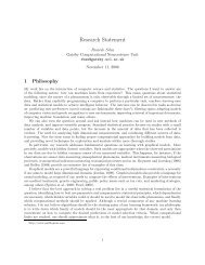
in a more or less regular grid. Initially, in Fig. 5A, each model node is linked to<br />
all input nodes. Consequently, each mean link position is centered in the middle of<br />
the image. With increasing inhibition controlled by ν in (6), control units are deactivated<br />
and the activity in a control column is restricted to an increasingly small<br />
3Final states of these systems are usually shifted diagonals which correspond to neighborhoodpreserving<br />
connectivities.<br />
4We did not visualize the cyclic neighborhood relationship (which would have resulted in all<br />
visualized positions having four edges) in order to make the translation of the grid in the input image<br />
with respect to the model grid more salient (compare Fig. 5E).<br />
14
A<br />
ν =<br />
0.40<br />
B<br />
ν =<br />
0.47<br />
C<br />
ν =<br />
0.50<br />
D<br />
ν =<br />
0.60<br />
E<br />
input<br />
u2<br />
u1<br />
u1<br />
W i<br />
active links<br />
u2<br />
W i+1<br />
model<br />
Figure 5: Time-course of map formation between the feature layers. Grid points in<br />
the right image of A-D represent the node positions in the model layer. Each model<br />
node has active links originating from potentially many nodes in the input layer and<br />
the average of all active links, the mean link position (13), is shown on the left-handside<br />
of A-D. With increasing inhibition (increasing ν) links are deactivated and the<br />
map converges from all-to-all (A) to one-to-one connectivity that links corresponding<br />
points within the limit of grid resolution (D). To illustrate the color coding, E<br />
shows a mapping that has formed between one-dimensional ‘images’ (bottom). Two<br />
of the active links together with their control columns are shown in magnification<br />
(top). The displayed connections between the active control units (small dark circles)<br />
support the parallel links of the formed mapping (compare Fig. 4).<br />
15
subset of units. In Fig. 5B this is reflected by the mean link positions starting to separate.<br />
In Fig. 5C the connectivity between the layers is already relatively sparse and,<br />
locally, neighboring control units in the model have often neighboring mean link<br />
positions in the input. In Fig. 5D the system has finally converged to a one-to-one<br />
connectivity structure in which the activities of the control columns are dominated<br />
by just one significantly active control unit each. The mean link positions, therefore,<br />
lie close to the grid-point positions of the input layer (compare Fig. 5E). The emergence<br />
of a regular grid puts in evidence that the final matrix W Mi,Ij corresponds to<br />
a neighborhood-preserving connectivity from I to M. If ν is further increased, the<br />
mean link positions are approaching the fixed grid positions more closely. By inspecting<br />
Fig. 5D we may conclude that the system has found the right neighborhood<br />
preserving correspondence map within the limits of the grid resolution. Note that<br />
the system can, depending on the input, converged to any planar translation within<br />
this resolution. More precise results could be obtained with finer grids, although at<br />
higher computational costs. The time-course for the reciprocal mapping from model<br />
to input layer (given by W Ii,Mj ) is very similar and results in the same correspondences.<br />
During the formation of the correspondence map, the feature columns represent<br />
the Gabor feature-vectors by subsets of active feature units. With increasingly strong<br />
inhibition, these subsets of active units get smaller. First, the feature units with<br />
smallest inputs are deactivated and finally only subsets of units with strong input<br />
remain active. During map formation, there are, however, always many feature units<br />
active (compare Lücke and von der Malsburg, 2006). Only for very high levels of<br />
inhibition, and after the map has formed, just one unit per feature column remains<br />
active. In simulations, both, the representation of feature vectors by subsets of active<br />
feature units, and their deactivation times have been found to be important for map<br />
formation.<br />
Figure 6: Result for the same image pair as used in Fig. 5 in the case of no topology<br />
term, i.e., CI in (5) is equal one. The figure shows the connectivity for ν = 0.6.<br />
Although the system was used with the same parameters otherwise, no correspondences<br />
were found.<br />
The resulting mean link positions for the same simulation as in Fig. 5A-D but<br />
without the influence of the topological connectivity (CI = 1) are shown in Fig. 6.<br />
16
In this case, the system has not converged to a neighborhood-preserving connectivity<br />
as is obvious from the irregular grid on the left. Its emergence is caused by ambiguities<br />
in feature vector similarities if image and model differ too much, as is the<br />
case for the image pair in Fig. 6. This influence of ambiguities, and the importance<br />
of a topology constraint, are documented in (Wiskott, 1999). For the other extreme<br />
of only topological input (CI = 0) the system converges, independent of the input<br />
image, to a neighborhood-preserving connectivity that, however, does not connect<br />
corresponding points (see Lücke and von der Malsburg, 2006, for such simulations<br />
with 1D layers). Only if feature information and the topological constraint are appropriately<br />
mixed using intermediate values for CI, the dynamics converges (in the<br />
limit of grid resolution) to the right correspondence map.<br />
A<br />
B<br />
Figure 7: An example of convergence to an imperfect map between model and feature<br />
layer. For the same system and parameters as in Fig. 5, we show connectivity<br />
matrices for ν = 0.6 for both, input to model mapping (W Mi,Ij ) in A, and<br />
model to input mapping (W Ii,Mj ) in B. In B the dynamics has converged to a global<br />
neighborhood-preserving mapping but in A the mapping is imperfect as some wrong<br />
correspondences between background and object have developed.<br />
The system has been simulated using various different image pairs. Accuracy<br />
of found correspondences can vary from image pair to image pair: highly distorted<br />
images of the same object and/or very different backgrounds can lead to the convergence<br />
to wrong correspondences. In general the network is, however, capable to find<br />
correspondences in pairs of very different images of the same object as illustrated<br />
by Fig. 5A-D or Fig. 7B.<br />
To illustrate the convergence to a mapping that is not globally neighborhood<br />
17
preserving consider Fig. 7A. The figure shows an imperfect match. Mean link positions<br />
of some control columns of the model layer show that the system has linked<br />
part of the background in the model to the object in the input. In this case, the<br />
lateral topological interaction has not been strong enough to force the system into<br />
a global neighborhood-preserving connectivity. However, correspondences of grid<br />
points on or in the vicinity of the object are found as accurately as permitted by<br />
grid resolution. Nodes at grid points on the background do actually not have correct<br />
correspondences if the backgrounds are different. In the case of Fig. 7A the feature<br />
dissimilarities between the background nodes have pushed some links out of the order<br />
of a regular mapping. If we use pairs of images that do not contain the same<br />
object, the emergence of irregular grids is the usual outcome.<br />
7 Discussion<br />
Finding homomorphic, that is, structure-preserving, mappings between neural feature<br />
layers — the correspondence problem — is a capability of fundamental importance<br />
for the brain, not only for the visual system (stereo matching, motion field<br />
extraction) or perceptual systems in general (invariant pattern recognition), but more<br />
fundamentally for the application of abstract schemas to concrete situations and analogical<br />
thinking, and thus for intelligence on all levels. By its very nature, correspondence<br />
requires for its establishment and expression neural implementation media for<br />
the formulation of structural relationships and for the expression of dynamic links.<br />
Both roles are played in our system by control columns.<br />
Our model describes neural population activities by abstract continuous variables,<br />
but as shown in previous work (Lücke, 2005) this is capturing the essential<br />
properties of a more direct modeling of a system of spiking neurons (Lücke and<br />
von der Malsburg, 2004). The essential assumption of these systems is the existence<br />
of relatively disjunct populations of interconnected excitatory neurons. In<br />
combined neuroanatomical and neurophysiological measurements such populations<br />
were found in (Yoshimura et al., 2005). The relation of these populations to the<br />
mainly anatomically investigated cortical minicolumns (which motivated the modeling<br />
of self-excitatory populations in our earlier work) has still to be investigated,<br />
however (see, e.g., Peters and Yilmaz, 1993; Peters and Sethares, 1996; Buxhoeveden<br />
and Casanova, 2002, for experimental data on minicolumns).<br />
Our model makes essential use of sigma-pi neurons, requiring sums of products<br />
of signals, cf. the first term in (5). Also the routing of information after correspondences<br />
are found has to rely on such mechanisms. Both cases involve control units,<br />
on the input side in one case, the output side in the other. The activity of control<br />
columns and of feature columns is described here by the same type of stochastic<br />
differential equations, Eqns. (3) and (4), but their connectivity patterns are markedly<br />
different. Control columns receive input from neighboring control units and, thus,<br />
form a network with lateral medium range connections. This network integrates input<br />
from afferents of inner- and extra-layer feature columns. The control column<br />
activity in this lateral network controls the inter-layer communication between fea-<br />
18
ture columns. In our system this control is modeled to be local. 5 These anatomical<br />
and neurophysiological characteristics may help to identify control units with known<br />
types of neurons 6 whose functional roles have yet to be understood (Olshausen and<br />
Field, 2005). Feature columns, on the other hand, express local structure and must<br />
be able to transmit it over distance.<br />
The facility for evaluating similarities of sets of neural signals in two feature<br />
columns makes it possible to represent whole feature spaces, instead of just single<br />
sample points as represented by sets of synaptic values in combination-coding<br />
neurons.<br />
Note that in our model, neurons of both control and feature columns, receive only<br />
weak afferent input compared to input from within their own self-excitatory population<br />
(small coupling κ in Eqns. 3 and 4). Such weak couplings are consistent with<br />
physiological and anatomical studies (e.g. Douglas and Martin, 2004; Yoshimura<br />
et al., 2005), which report that cells in excitatory neural populations are much more<br />
strongly coupled to input from within their population than to medium and longrange<br />
afferent input. Our simulations show that such a system can, nevertheless, be<br />
very sensitive to external stimuli. Excitation and inhibition are kept in balance, but<br />
with increasing inhibition, afferent input can break the initial activity symmetry.<br />
Our system solves several problems with previous models. One of them is the<br />
neural evaluation of feature similarities, which was a problem for (Zhu and von der<br />
Malsburg, 2004), (Olshausen et al., 1993) and (Wiskott and von der Malsburg, 1995).<br />
Another is excessive time requirement in (Wiskott and von der Malsburg, 1995). In<br />
the system presented, neural correspondence finding is possible in very small time<br />
intervals because of the use of a balanced network with population rates. The velocity<br />
of the system depends on the time required to deactivate neural populations.<br />
In simulations on the basis of single spiking neurons (Lücke and von der Malsburg,<br />
2004), 25 ms have been found to be sufficient for these deactivations. The time constant<br />
a in Eqn. 1 has been chosen to reproduce those deactivation times in the abstract<br />
dynamics here used (compare Lücke, 2005; Lücke and Bouecke, 2005). The exact<br />
value of the time constant is difficult to determine as it can to some extent depend<br />
on details of neural time constants and connectivity within populations. However,<br />
even if neural spike and refraction times in (Lücke and von der Malsburg, 2004)<br />
are estimated conservatively, the length of the deactivation period is on the order of<br />
just a few tens of milliseconds. Thus, although difficult to determine exactly, the<br />
required order of magnitude for a that reproduces such deactivation times allows us<br />
to infer that convergence of the dynamics here presented is possible in times well<br />
below 100 ms.<br />
In this paper we have considered pairs of images as input to our system. For<br />
each pair we have started from fully active control columns which corresponds to<br />
all-to-all connectivity between the feature layers. The cyclically changing inhibition<br />
(6) represents not only a mechanism that, by increasing inhibition, forces the system<br />
5 On the other hand, since a specific activated correspondence map constitutes valuable information<br />
in itself, as pointed out in (Arathorn, 2002), it might be advantageous for control neurons also to<br />
project over longer distances.<br />
6 For the hypothesis that control units are constituted by astrocytes see (Möller et al., 2007).<br />
19
to converge but also a mechanism to reset the system after such a convergence. In a<br />
potential extension of the system, the cyclically driven inhibition could be exploited<br />
further: e.g., if the input is moving, it seems unrealistic to operate the system by<br />
resetting it to all-to-all connectivity multiple times in a second. Instead the map between<br />
the layers can partially be reset by preventing the inhibition (6) from dipping<br />
to low values during the oscillation. In this way the system would take the previously<br />
found correspondence as a prior for the next. Similarly, local distortions of<br />
objects could be addressed more actively: e.g., if a neighborhood preserving map<br />
between two images has been found after a first ν-cycle, the map could be refined<br />
by a partial reset and a second ν-cycle with less emphasis on the topology term in<br />
(5).<br />
There are some more challenges ahead of us. Thus it is unrealistic to assume<br />
all links between the input layer and the model layer (which presumably are to be<br />
identified with primary visual cortex and infero-temporal cortex, resp.) to be direct.<br />
This would require a potentially unrealistic number of axons to converge on one<br />
unit. As proposed in (Olshausen et al., 1993), this problem is very likely solved in<br />
the brain with the help of intermediate layers to reduce the necessary fan-in and the<br />
number of required connections (Wolfrum and von der Malsburg, 2007). Further,<br />
whereas in the present system the model layer contains just one pattern that is to be<br />
compared to the image layer, the object recognition problem has to select the right<br />
model from a layer containing dozens of thousands of stored patterns. This will<br />
require a control hierarchy to load appropriate patterns into our model layer, and a<br />
bootstrap mechanism to overcome the simultaneous ambiguity of object location on<br />
the input side and object identity on the model side. Yet another important problem<br />
area is to develop a clear picture of the ontogenesis of the highly specific connectivity<br />
patterns required for our system.<br />
Acknowledgments<br />
We thank Yasser Roudi, Junmei Zhu, and Cornelius Weber for valuable comments<br />
on earlier versions of this manuscript and gratefully acknowledge funding by the<br />
<strong>Gatsby</strong> Charitable Foundation, the Hertie Foundation, and by the EU project FP6-<br />
2005-015803.<br />
References<br />
Arathorn, D. (2002). Map-Seeking circuits in Visual Cognition — A <strong>Computational</strong><br />
Mechanism for Biological and Machine Vision. Standford Univ. Press, Stanford,<br />
California.<br />
Aristotle (1984). On memory. In Barnes, J., editor, The Complete Works of Artistotle,<br />
pages 714 – 720. Princeton Univ. Press, Princeton, New Jersey.<br />
20
Bell, A. J. and Sejnowski, T. J. (1997). The ”independent components” of natural<br />
scenes are edge filters. Vision Research, 37(23):3327 – 38.<br />
Buxhoeveden, D. P. and Casanova, M. F. (2002). The minicolumn and evolution of<br />
the brain. Brain, Behavior and Evolution, 60:125–151.<br />
Dev, P. (1975). Perception of depth surfaces in random dot stereograms: a neural<br />
model. International Journal of Man-Machine Studies, 7:511–528.<br />
Douglas, R. J. and Martin, K. A. C. (2004). Neuronal circuits of the neocortex.<br />
Annual Review of <strong>Neuroscience</strong>, 27:419 – 451.<br />
Favorov, O. V. and Diamond, M. (1990). Demonstration of discrete place-defined<br />
columns, segregates, in cat SI. Journal of Comparative Neurology, 298:97 – 112.<br />
Hinton, G. E. (1981). A parallel computation that assigns canonical object-based<br />
frames of reference. In Proc. IJCAI, pages 683 – 685.<br />
Hubel, D. H. and Wiesel, T. N. (1977). Functional architecture of macaque visual<br />
cortex. Proceedings of the Royal Society of London B, 198:1 – 59.<br />
Jones, J. P. and Palmer, L. A. (1987). An evaluation of the two-dimensional Gabor<br />
filter model of simple receptive fields in cat striate cortex. Journal of Neurophysiology,<br />
58(6):1233 – 1258.<br />
Kree, R. and Zippelius, A. (1988). Recognition of topological features of graphs<br />
and images in neural networks. Journal of Physics A, 21:813 – 818.<br />
Lücke, J. (2004). Hierarchical self-organization of minicolumnar receptive fields.<br />
Neural Networks, 17/8–9:1377 – 1389.<br />
Lücke, J. (2005). Dynamics of cortical columns – sensitive decision making. In<br />
Proc. ICANN, LNCS 3696, pages 25 – 30. Springer.<br />
Lücke, J. (2007). A Dynamical Model for Receptive Field Self-Organization in V1<br />
Cortical Columns. Proc. ICANN, LNCS 4669, pages 389 – 398. Springer.<br />
Lücke, J. and Bouecke, J. D. (2005). Dynamics of cortical columns – selforganization<br />
of receptive fields. In Proc. ICANN, LNCS 3696, pages 31 – 37.<br />
Springer.<br />
Lücke, J. and von der Malsburg, C. (2004). Rapid processing and unsupervised<br />
learning in a model of the cortical macrocolumn. Neural Computation, 16:501 –<br />
533.<br />
Lücke, J. and von der Malsburg, C. (2006). Rapid correspondence finding in networks<br />
of cortical columns. In Proc. ICANN, LNCS 4131, pages 668 – 677.<br />
Springer.<br />
21
Lücke, J., von der Malsburg, C., and Würtz, R. P. (2002). Macrocolumns as decision<br />
units. In Proc. ICANN, LNCS 2415, pages 57 – 62. Springer.<br />
Marr, D. and Poggio, T. (1976). Cooperative computation of stereo disparity. Science,<br />
194:283–287.<br />
Messer, K., Kittler, J., Sadeghi, M., Hamouz, M., Kostin, et al. (2004). Face authentication<br />
test on the BANCA database. In Proc. ICPR, Cambridge, volume 4,<br />
pages 523 – 532.<br />
Möller, C., Lücke, J., Zhu, J., Faustmann, P. M., and von der Malsburg, C. (2007).<br />
Glial cells for information routing? Cognitive Systems Research, 8(1):28 – 35.<br />
Mountcastle, V. B. (1997). The columnar organization of the neocortex. Brain,<br />
120:701 – 722.<br />
Okada, K., Steffens, J., Maurer, T., Hong, H., Elagin, E., Neven, H., and von der<br />
Malsburg, C. (1998). The Bochum/USC face recognition system and how it fared<br />
in the FERET phase III test. In Wechsler, H., Phillips, P., Bruce, V., F.Fogelman-<br />
Soulie, and Huang, T., editors, Face Recognition : From Theory to Applications,<br />
pages 186 – 205. Springer-Verlag.<br />
Olshausen, B. A., Anderson, C. H., and Essen, D. C. V. (1993). A neurobiological<br />
model of visual attention and invariant pattern recognition based on dynamic<br />
routing of information. The Journal of <strong>Neuroscience</strong>, 13(11):4700 – 4719.<br />
Olshausen, B. A. and Field, D. J. (1996). Emergence of simple-cell receptive field<br />
properties by learning a sparse code for natural images. Nature, 381:607 – 609.<br />
Olshausen, B. A. and Field, D. J. (2005). 23 Problems in Systems <strong>Neuroscience</strong>,<br />
chapter What is the other 85% of V1 doing? Oxford University Press.<br />
Peters, A. and Sethares, C. (1996). Myelinated axons and the pyramidal cell modules<br />
in monkey primary visual cortex. Journal of Comparative Neurology, 365:232 –<br />
255.<br />
Peters, A. and Yilmaz, E. (1993). Neuronal organization in area 17 of cat visual<br />
cortex. Cerebral Cortex, 3:49 – 68.<br />
Philips, P. J., Moon, H., Rizvi, S. A., and Rauss, P. J. (2000). The FERET evaluation<br />
methodology for face-recognition algorithms. IEEE Transactions on Pattern<br />
Analysis and Machine Intelligence, 22(10):1090–1104.<br />
Ringach, D. L. (2002). Spatial structure and symmetry of simple-cell receptive fields<br />
in macaque primary visual cortex. Journal of Neurophysiology, 88:455 – 463.<br />
Thorpe, S., Fize, F., and Marlot, C. (1996). Speed of processing in the human visual<br />
system. Nature, 381:520 – 522.<br />
22
Wiskott, L. (1999). Role of topographical constraints in face recognition. Pattern<br />
Recognition Letters, 20(1):89–96.<br />
Wiskott, L., Fellous, J.-M., Krüger, N., and von der Malsburg, C. (1995). Face recognition<br />
and gender determination. International Workshop on Automatic Face- and<br />
Gesture-Recognition, Zürich, June 26-28, 1995.<br />
Wiskott, L. and von der Malsburg, C. (1995). Face recognition by dynamic<br />
link matching. In Sirosh, J., Miikkulainen, R., and Choe, Y., editors,<br />
Lateral Interactions in the Cortex: Structure and Function, chapter 4.<br />
www.cs.utexas.edu/users/nn/book/bwdraft.html. ISBN 0-9647060-0-8.<br />
Wolfrum, P. and von der Malsburg, C. (2007). What is the optimal architecture for<br />
visual information routing? Neural Computation, 19(12):3293 – 3309.<br />
Yoshimura, Y., Dantzker, J. L. M., and Callaway, E. M. (2005). Excitatory cortical<br />
neurons form fine-scale functional networks. Nature, 433:868 – 873.<br />
Zhu, J. and von der Malsburg, C. (2004). Maplets for correspondence-based object<br />
recognition. Neural Networks, 17/8–9:1311 – 1326.<br />
23