Major 4a - Funktronic
Major 4a - Funktronic
Major 4a - Funktronic
Create successful ePaper yourself
Turn your PDF publications into a flip-book with our unique Google optimized e-Paper software.
English 2.0<br />
<strong>Major</strong> <strong>4a</strong><br />
Kompetent für Elektroniksysteme
Contents<br />
Delivery 2<br />
Order Information 2<br />
Technical Data 2<br />
Control Elements <strong>Major</strong> <strong>4a</strong> 3<br />
General features 3<br />
Rearview <strong>Major</strong> <strong>4a</strong> 4<br />
Sockets pinout <strong>Major</strong> <strong>4a</strong> 4<br />
Connecting <strong>Major</strong> <strong>4a</strong> (5a) --> Two-Way-Radio via multiwire 5<br />
Connecting <strong>Major</strong> <strong>4a</strong> (5a) --> Line Interface LIM-AC 5<br />
Keypad layout in programming mode 6<br />
Menu structure 6<br />
Hardware confi guration 9<br />
2/4-wire confi guration 9<br />
2-wire confi guration with FT630 9<br />
Programming short call 10<br />
Software confi guration 10<br />
Individual programming of the buttons 11<br />
Permanent digits of encoder 12<br />
Transmitting 6/7/8-tone 13<br />
sequences 13<br />
Channel scanning function 13<br />
Reset to factory defaults 14<br />
Sample confi gurations <strong>Major</strong> <strong>4a</strong> (5a) 15<br />
Table of registers <strong>Major</strong> <strong>4a</strong> 16<br />
Release Notes 24<br />
Technical Data<br />
Voltage of operation 12 V<br />
Current max. 800 mA<br />
Weight 1,5 kg<br />
Dimensions (without gooseneck microphone) 245 x 220 x 95 mm<br />
Input impedance 2/4-wire 600 Ohm<br />
Output impedance 2/4-wire 600 Ohm<br />
Order Information<br />
Ord.-No. Description<br />
681000 <strong>Major</strong> <strong>4a</strong><br />
900012 Power Supply 230/12 Volt<br />
Delivery<br />
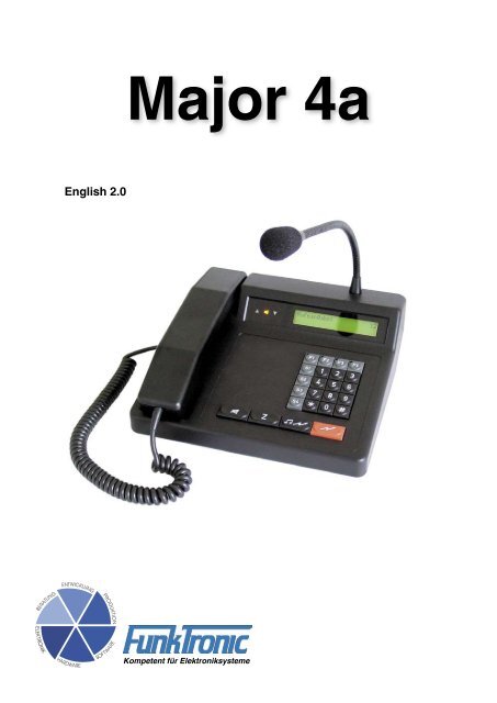
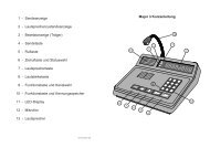
<strong>Major</strong> <strong>4a</strong> with handset and gooseneck microphone<br />
Power plug<br />
Power Supply not delivert with<br />
Kompetent für Elektroniksysteme<br />
- 2 -<br />
m<strong>4a</strong>_eng2_0 (09.11.04)
Control Elements <strong>Major</strong> <strong>4a</strong><br />
m<strong>4a</strong>_eng2_0 (09.11.04)<br />
Handset<br />
with PTT button<br />
General features<br />
Gooseneck microphone<br />
Status LED´s<br />
Short call button<br />
Call button<br />
Loudspeaker button<br />
- 3 -<br />
PTT button<br />
LC Display<br />
Function buttons<br />
Special buttons<br />
The <strong>Major</strong> <strong>4a</strong> is the newer design of the well kown <strong>Major</strong> 4. The Display was replaced by an alphanumeric<br />
LC Display with background illumination. A gooseneck microphone with high dynamics has<br />
come to it. The programming possibilities were essentially widened and strongly simplifi ed by clear<br />
text menu structure.<br />
There are two sockets for headsets. One is normaly used for a PTT foot button. The 7 digital outputs<br />
are normaly used for channel switching or also other functions. For operation a 12 volt power supply<br />
is necessary.<br />
The <strong>Major</strong> <strong>4a</strong> can be programmed via the serial interface or keypad. It is also possible to connect a<br />
printer or terminal on the serial interface. For printers with parallel interface is an optionaly interface<br />
available.<br />
Kompetent für Elektroniksysteme
Rearview <strong>Major</strong> <strong>4a</strong><br />
Sockets pinout <strong>Major</strong> <strong>4a</strong><br />
All sockets shown from rear few.<br />
Kompetent für Elektroniksysteme<br />
Pinout Radio socket ST1,<br />
rearview<br />
AF input B 1<br />
AF input A 2<br />
Squelch input 3<br />
GND 4<br />
+12 V, max. 200 mA 5<br />
Transmit active low 6<br />
AF output A 7<br />
AF output B 8<br />
All audio in/outputs equiped with transformers.<br />
PIN 5 is for supply (+12V) of external devices<br />
(LIM-AC, FT634C, FT633AC).<br />
Attention, not for supply of radio, because of<br />
only 200 mA output current.<br />
Pinout<br />
RS232 ST4<br />
NC 1<br />
NC 2<br />
TxD 3<br />
RxD 4<br />
GND 5<br />
NC 6<br />
To the RS232 socket you can connect a printer<br />
for messages.<br />
ST1 Radio socket ST = socket<br />
ST2 Headset 1<br />
ST2A Headset 2<br />
ST3 Digital outputs<br />
ST4 Serial interface RS232<br />
PWR Power supply 12V, max. 1,5 A<br />
inside positive, outside ground<br />
- 4 -<br />
Pinout headset 1 + 2,<br />
ST2 and ST2A<br />
GND 1<br />
GND ST2, AF mic. ST2A 2<br />
AF earphone 3<br />
GND earphone 4<br />
GND ST2A, AF mic. ST2 5<br />
PTT, active GND 6<br />
There are two sockets for connecting a headset.<br />
One is for connecting headset, the other for use<br />
of external PTT-Button.<br />
Pinout ST3<br />
digital in/outputs<br />
OUT0 1<br />
OUT1 2<br />
OUT2 3<br />
OUT3 4<br />
OUT4 5<br />
OUT5 6<br />
OUT6 7<br />
GND 8<br />
The digital PINs are for use as in- or outputs. Most<br />
they are used for remote control of channels.<br />
m<strong>4a</strong>_eng2_0 (09.11.04)
Connecting <strong>Major</strong> <strong>4a</strong> (5a) --> Two-Way-Radio via multiwire<br />
All audio in/outputs of <strong>Major</strong> <strong>4a</strong> (5a) are equiped with transformers. No PINs are grounded, therefore<br />
one must be connected to ground at the two-way-radio. We suggest to ground PIN 1 and 8 at the<br />
radio.<br />
PIN 5 is for supply (+12V) of external devices (LIM-AC, FT634C, FT633AC). Attention, not for<br />
supply of radio, because of only 200 mA output current.<br />
Connecting <strong>Major</strong> <strong>4a</strong> (5a) --> Line Interface LIM-AC<br />
The line interface LIM-AC is simply connected via a 8-wire patch cable (like used for ethernet) to the<br />
<strong>Major</strong> <strong>4a</strong> (5a).<br />
m<strong>4a</strong>_eng2_0 (09.11.04)<br />
- 5 -<br />
Kompetent für Elektroniksysteme
Keypad layout in programming mode<br />
The button decrements and the button increments.<br />
The buttons S1 to S4, the * button and the # button are<br />
concerned with A to F.<br />
Menu structure<br />
Simultaneous pressing of the * button and the # button you get into the menu. With the but-<br />
ton you switch to the next menu point. With the button the selected menu point is activated.<br />
select number:<br />
* simultaneously #<br />
- put in the register you want<br />
to program<br />
- with 222 the factory default<br />
values are programmed<br />
- overwrite the Code with<br />
your values<br />
= escape menu without<br />
change<br />
= store value, escape<br />
menu<br />
Kompetent für Elektroniksysteme<br />
È<br />
EEPROM programming : F4<br />
Next menu : F3<br />
Register:<br />
Register: 000<br />
Code 12345<br />
Software version : F4<br />
Next menu : F3<br />
Æ Æ<br />
È È È<br />
Software: <strong>Major</strong> <strong>4a</strong> V1.24<br />
Date : 23.09.04<br />
- displayed for 3 seconds<br />
- 6 -<br />
-<br />
¡123 45 8<br />
0 9 7<br />
*<br />
6<br />
S1<br />
A<br />
¡<br />
#<br />
E F<br />
B<br />
S2<br />
¡ C<br />
S3<br />
¡ D<br />
S4<br />
1 = Input level<br />
2 = Output level<br />
3 = Gooseneck<br />
microphone level<br />
4 = Handset microphone<br />
level<br />
5 = Headset microphone<br />
level<br />
6 = DTMF output level<br />
- the adjustment area of the<br />
Pots is 0-63<br />
- input direct via the keypad<br />
or<br />
+<br />
Level settings : F4<br />
Next menu : F3<br />
Poti-Nr. (1-6):<br />
= value increment<br />
= value decrement<br />
= escape menu without<br />
change<br />
= store value, escape<br />
menu<br />
m<strong>4a</strong>_eng2_0 (09.11.04)
Menu structure<br />
Continuation<br />
select number:<br />
* simultaneously #<br />
È<br />
0 = 200 Hz<br />
1 = 300 Hz<br />
2 = 400 Hz<br />
3 = 600 Hz<br />
4 = 800 Hz<br />
5 = 1000 Hz<br />
6 = 1600 Hz<br />
7 = 2400 Hz<br />
8 = 3400 Hz<br />
9 = 4000 Hz<br />
S1 = 2900 Hz<br />
S2 = 3000 Hz<br />
S3 = 3100 Hz<br />
S4 = 3300 Hz<br />
* = 1200 Hz<br />
# = 1800 Hz<br />
m<strong>4a</strong>_eng2_0 (09.11.04)<br />
Æ Æ Æ<br />
Transmit test tone : F4<br />
Next menu : F3<br />
È<br />
Change frequency 0.....C<br />
F3 for ESC Hz<br />
= escape menu<br />
Æ<br />
Adjust contrast : F4<br />
Next menu : F3<br />
È<br />
Displaycontrast: 90<br />
F1- F2+ F3ESC F4STORE<br />
= decrement contrast<br />
= increment contrast<br />
= escape menu without<br />
change<br />
= store value, escape<br />
menu<br />
- 7 -<br />
Æ<br />
Set date/time : F4<br />
Next menu : F3<br />
È<br />
15.10.04 22:47:01<br />
= one digit left<br />
= one digit right<br />
= escape menu without<br />
change<br />
= store value, escape<br />
menu<br />
Put in the values you want<br />
with the keypad 0 to 9.<br />
Kompetent für Elektroniksysteme
Menu structure<br />
Continuation<br />
select number:<br />
* simultaneously #<br />
È<br />
The clock is already adjusted<br />
in factory. Note down<br />
the values for digital and<br />
analog before changing.<br />
Biger values accelerate and<br />
smaller values slows down<br />
the clock.<br />
Change in digital makes<br />
more alteration then in analog.<br />
Fine adjustment should<br />
be done in analog, step by<br />
step.<br />
Kompetent für Elektroniksysteme<br />
Æ Æ Æ<br />
Æ Æ Æ<br />
Adjust clock : F4<br />
Next menu : F3<br />
È<br />
Digital (0-6) : 3<br />
Analog (00-59): 29<br />
= one digit left<br />
= one digit right<br />
= escape menu without<br />
change<br />
= store value, escape<br />
menu<br />
Æ<br />
Serial number : F4<br />
Next menu : F3<br />
È<br />
Serial number: 1111-22<br />
Mainboard : FFFF/FF<br />
- displayed for 3 seconds<br />
- 8 -<br />
m<strong>4a</strong>_eng2_0 (09.11.04)
Hardware confi guration<br />
2/4-wire confi guration<br />
The <strong>Major</strong> <strong>4a</strong> (5a) is for use on 2- or 4-wire line. For 2-wire line jumper 1 have to be set. Remove<br />
jumper 1 for 4-wire line.<br />
2-wire confi guration with FT630<br />
For remote control of radio over longer distance it is adviceable to use a 2-wire line with the FT630.<br />
The FT630 transmitts and receives the PTT and SQUELCH state via DC.<br />
If there is no DC way on the line or also remote channel control necessary, we suggest to use FT634C<br />
or FT633AC.<br />
m<strong>4a</strong>_eng2_0 (09.11.04)<br />
- 9 -<br />
Kompetent für Elektroniksysteme
Software confi guration<br />
Programming short call<br />
The example below shows the programming of<br />
short call 1 in register 001 with tone sequence<br />
12345.<br />
Kompetent für Elektroniksysteme<br />
select number:<br />
* simultaneously #<br />
È<br />
EEPROM programming : F4<br />
Next menu : F3<br />
Register:<br />
È<br />
0<br />
0<br />
1<br />
È<br />
Register: 001<br />
Code 12345<br />
The line „Code“ shows the current programming.<br />
Overwrite with your values.<br />
Key F3 escapes without any changes.<br />
Key F4 stores the displayed values.<br />
Each button of the <strong>Major</strong> <strong>4a</strong> can be programmed<br />
with any function. Register 174 and 175 has to<br />
be programmed with the appropriate values of the<br />
short call button (Z-Button).<br />
Register 174 is for the function after short<br />
activation of Z-Button and register 175 after<br />
longer activation.<br />
Register 174 is coded with 22F01 and register<br />
175 with 00000.<br />
The leading zero in register 175 disables action<br />
after long pushing Z-Button.<br />
- 10 -<br />
The digits in register 174 activates the following<br />
functions:<br />
1. digit = 2 --> function 2 - transmit call<br />
sequence<br />
2. digit = 2 --> short call<br />
3. digit = F --> input necessary<br />
4. digit = 0 --> 5 tone sequence<br />
5. digit = 1 --> not applicable<br />
Follow next steps to view or change the values in<br />
register 174 and 175.<br />
select number:<br />
* simultaneously #<br />
È<br />
EEPROM programming : F4<br />
Next menu : F3<br />
Register:<br />
È<br />
1 74<br />
È<br />
Register: 174<br />
Code 12345<br />
È<br />
Register: 174<br />
EEPROM programmed<br />
Register:<br />
È<br />
È<br />
Funk Tronic <strong>Major</strong> <strong>4a</strong><br />
select number:<br />
m<strong>4a</strong>_eng2_0 (09.11.04)
Individual programming of the buttons<br />
It is possible to program each button of the <strong>Major</strong><br />
<strong>4a</strong> with two different functions.<br />
The key down time selects one of the two. Pushing<br />
the button shorter than one second activates the<br />
function listed for „short push“ and longer pushing<br />
activates the function listed for „long push“.<br />
The action for short push is activated immediately,<br />
if nothing is programmed for long push.<br />
Each register has 5 digits. The fi rst digit selects<br />
the function. Digit 2 to 5 depends on the function<br />
programmed in fi rst digit.<br />
Sample for coding button - 1.<br />
Programming „short bush“:<br />
m<strong>4a</strong>_eng2_0 (09.11.04)<br />
select number:<br />
* simultaneously #<br />
È<br />
EEPROM programming : F4<br />
Next menu : F3<br />
Register:<br />
È<br />
1 32<br />
È<br />
Register: 132<br />
Code 71100<br />
1. digit 7 = function --> enter select number<br />
2. digit 1 = new input<br />
3. digit 1 = delete only last input<br />
4. digit 0 = not applicable<br />
5. digit 0 = not applicable<br />
- 11 -<br />
To store the inputs, follow the next steps.<br />
È<br />
È<br />
È<br />
Normally there is no programming for long push<br />
of button 1 .<br />
Register: 132<br />
EEPROM programmed<br />
Register:<br />
Funk Tronic <strong>Major</strong> <strong>4a</strong><br />
select number:<br />
Next sample shows programming level 1 loudness<br />
for the speaker.<br />
Programming „long bush“:<br />
select number:<br />
* simultaneously #<br />
È<br />
EEPROM programming : F4<br />
Next menu : F3<br />
Register:<br />
È<br />
1 33<br />
È<br />
Register: 133<br />
Code 00000<br />
Kompetent für Elektroniksysteme
The value 00000 in register 133 hase to be<br />
changed in 41100.<br />
Kompetent für Elektroniksysteme<br />
4 1 10 0<br />
È<br />
Register: 133<br />
Code 41100<br />
1. digit 4 = function --> adjust volume<br />
2. digit 1 = volume --> adjust<br />
3. digit 1 = volume level 1<br />
4. digit 0 = not applicable<br />
5. digit 0 = not applicable<br />
To store the inputs, follow the next steps.<br />
È<br />
Register: 133<br />
EEPROM programmed<br />
Register:<br />
È<br />
È<br />
Funk Tronic <strong>Major</strong> <strong>4a</strong><br />
select number:<br />
Now bush button 1 one times short and one<br />
long.<br />
After short bushing the display shows 1.<br />
Long bushing activates volume level 1 at the<br />
loudspeaker.<br />
- 12 -<br />
Permanent digits of encoder<br />
Register 010 defi nes the number of permanent<br />
coded digits of the encoder.<br />
If „FFFFF“ is coded in register 010, all 5 digits has<br />
to be entered via keypad.<br />
For example, if digit 1,2 and 4 are permanent and<br />
digit 3 and 5 entered via keypad, register 010<br />
should be coded with 34F5F.<br />
Sample, entering all 5 digits via keypad:<br />
select number:<br />
* simultaneously #<br />
È<br />
EEPROM programming : F4<br />
Next menu : F3<br />
Register:<br />
È<br />
0 10<br />
È<br />
Register: 010<br />
Code FFFFF<br />
È<br />
Register: 010<br />
EEPROM programmed<br />
Register:<br />
È<br />
È<br />
Funk Tronic <strong>Major</strong> <strong>4a</strong><br />
select number:<br />
m<strong>4a</strong>_eng2_0 (09.11.04)
Transmitting 6/7/8-tone<br />
sequences<br />
To transmit a 8-tone sequence, the following<br />
coding is necessary. The fi rst 5 digits entered<br />
via keypad and the last 3 are used from register<br />
015.<br />
Register 172:<br />
m<strong>4a</strong>_eng2_0 (09.11.04)<br />
select number:<br />
* simultaneously #<br />
È<br />
EEPROM programming : F4<br />
Next menu : F3<br />
Register:<br />
È<br />
0 15<br />
È<br />
Register: 015<br />
Code 98765<br />
Register:<br />
1 72<br />
È<br />
Register: 172<br />
Code 20050<br />
2 = transmit call sequence<br />
0 = entered call<br />
0 = not applicable<br />
5 = 8 tone sequence<br />
0 = not applicable<br />
The 8-tone sequence are conglomerated from 5<br />
entered via keypad and the last 3 from register<br />
015 (Personaly identifi cation code).<br />
- 13 -<br />
Channel scanning function<br />
The channel scanning function is activated if<br />
the waiting time (register 067/5) is different from<br />
zero.<br />
The scanner waits at least for the programmed<br />
waiting time on each channel. Just before the<br />
end of waiting time, channel is checked for a<br />
carrier. Scanning is going on if there is no carrier<br />
detected.<br />
Scanner holds on carrier if scanner stop on carrier<br />
(register 068/1) is programmed. Otherwise the<br />
scanner is stopped for additionally 100 ms. During<br />
this period it is checked if a tone is detected. If it<br />
is true, the scanner waits for scan waiting time in<br />
register 068/2+3. Detecting a tone sequence stops<br />
scanning, otherwise scanning is continued.<br />
The channels coded in register 067/1-4 are<br />
scanned or the channels in register 070-074, if<br />
register 067/1+2 is coded with E.<br />
The prematurely end of table is coded with FF.<br />
For example, if channels 1, 5 and 6 shout be<br />
scanned, register 070 is coded with 0105x and<br />
register 071 with 06FFx.<br />
The scanner is triggered with carrier and PTT<br />
and stops for loudspeaker time (050/1-3) with<br />
decoding.<br />
Scanning is going on after putting down the handset,<br />
if register 050/5 is coded accordingly.<br />
The scanner is switched off, if the loudspeaker is<br />
switched on manually.<br />
Kompetent für Elektroniksysteme
Reset to factory defaults<br />
The following steps resets the <strong>Major</strong> to factory<br />
defaults.<br />
Attention, all parameters reseted without<br />
acknowledgement.<br />
Kompetent für Elektroniksysteme<br />
select number:<br />
* simultaneously #<br />
È<br />
EEPROM programming : F4<br />
Next menu : F3<br />
Register:<br />
È<br />
2 22<br />
È<br />
program EEPROM with<br />
default values<br />
select number:<br />
- 14 -<br />
m<strong>4a</strong>_eng2_0 (09.11.04)
Sample confi gurations <strong>Major</strong> <strong>4a</strong> (5a)<br />
The next sketch shows a simple way for remote control a radio using <strong>Major</strong> <strong>4a</strong> (5a). Only a 7-wire line (Audio,<br />
squelch, PTT) is needed if no remote channel control is necessary.<br />
m<strong>4a</strong>_eng2_0 (09.11.04)<br />
FT634C<br />
FT633AC<br />
LIM-AC (only 2-wire)<br />
LIM AC<br />
LIM AC<br />
2<br />
7 Audio, Squelch, PTT<br />
max. 8 Remote channel control<br />
The next assembly is used, if there is only a 2-wire line available or for longer distance. Remote<br />
channel control and duplex mode is not possible.<br />
2<br />
Next sample shows assembly for duplex mode via 4-wire line or simplex mode via 2-wire line.<br />
Also remote channel control is possible.<br />
2 oder 4<br />
2 oder 4<br />
- 15 -<br />
FT634C (channel control possible)<br />
FT633AC (channel control possible)<br />
FT634 (channel control not possible)<br />
For assemblies not using private lines, the following confi guration is suggested (PTT certifi cated).<br />
2<br />
FT624<br />
FT630-2<br />
without remote channel control<br />
FT634C (channel control possible)<br />
FT633AC (channel control possible)<br />
FT634 (channel control not possible)<br />
<strong>Major</strong> in parallel circuit --> LIM AC has to be equiped<br />
with notch for PTT-Tone.<br />
2<br />
FT634C (channel control possible)<br />
FT633AC (channel control possible)<br />
FT634 (channel control not possible)<br />
Kompetent für Elektroniksysteme
Table of registers <strong>Major</strong> <strong>4a</strong><br />
Register Function<br />
000 Short call 0<br />
001 Short call 1<br />
002 Short call 2<br />
003 Short call 3<br />
004 Short call 4<br />
005 Short call 5<br />
006 Short call 6<br />
007 Short call 7<br />
008 Short call 8<br />
009 Short call 9<br />
010 Permanently coded positions<br />
of 5-tone encoder<br />
011 Monitor after switch on<br />
4. Digit 0 = off; 1 = on<br />
014 Intercom-Tonesquence (DCBA)<br />
5. Digit -> wake up on decoding<br />
with 1 sec. duration<br />
and act. loudness<br />
015 Personaly identification code<br />
(= ID-code)<br />
016 Key tones for decoding<br />
017 Standard acknowledgement<br />
019 Key tones for printer output<br />
020 Decoder 1<br />
021 Decoder 2<br />
022 Decoder 3<br />
023 Decoder 4<br />
024 Decoder 5<br />
025 Decoder 6<br />
026 Decoder 7<br />
027 Decoder 8<br />
028 Decoder 9<br />
029 Decoder 10<br />
Kompetent für Elektroniksysteme<br />
- 16 -<br />
Register Function<br />
030 Setting 1 for decoder 1<br />
1. Digit -> wake up tone type<br />
0 = no wake up tone<br />
1-A = wake up tone 1 to A<br />
B-F = wake up tone 1-5,<br />
10 repetitions<br />
2. Digit -> wake up tone length<br />
0 = allways<br />
1-F = n * 200 msec<br />
3. Digit -> wake up tone volume<br />
0-9 = volume 0-9<br />
A-F = offset for current volume<br />
4. Digit -> ringing volume length<br />
0 = allways<br />
1-F = n * 1 sec.<br />
5. Digit -> ringing volume<br />
0-9 = volume 0-9<br />
A-F = offset for current volume<br />
031 Setting 1 for decoder 2<br />
032 Setting 1 for decoder 3<br />
033 Setting 1 for decoder 4<br />
034 Setting 1 for decoder 5<br />
035 Setting 1 for decoder 6<br />
036 Setting 1 for decoder 7<br />
037 Setting 1 for decoder 8<br />
038 Setting 1 for decoder 9<br />
039 Setting 1 for decoder 10<br />
m<strong>4a</strong>_eng2_0 (09.11.04)
Register Function Register Function<br />
040 Setting 2 for decoder 1<br />
1. Digit -> ID mode<br />
0 = 5 tone sequence<br />
1 = call sequence -> ID-code<br />
dual sequence<br />
2 = ID-code -> call sequence<br />
dual sequence<br />
3 = 6 tone sequence<br />
4 = 7 tone sequence<br />
5 = 8 tone sequence<br />
6 = not used<br />
7 = no ID-code<br />
m<strong>4a</strong>_eng2_0 (09.11.04)<br />
2. Digit -> digital output number<br />
0 = none<br />
1-7 = digital output number<br />
3. Digit -> digital output time<br />
0 = off<br />
F = on<br />
1-E = 1-14 sec<br />
4. Digit -> acknowledgement<br />
0 = no acknowledgement<br />
1 = acknowledgement<br />
2 = single tone<br />
3 = Personaly ID-code<br />
4 = received code<br />
041 Setting 2 for decoder 2<br />
042 Setting 2 for decoder 3<br />
043 Setting 2 for decoder 4<br />
044 Setting 2 for decoder 5<br />
045 Setting 2 for decoder 6<br />
046 Setting 2 for decoder 7<br />
047 Setting 2 for decoder 8<br />
048 Setting 2 for decoder 9<br />
049 Setting 2 for decoder 10<br />
- 17 -<br />
050 Setting of loudspeaker timer<br />
1. Digit = n * 100 sec<br />
2. Digit = n * 10 sec<br />
3. Digit = n * 1 sec<br />
1.-3. Digit = 000 -> off<br />
1.-3. Digit = 000 -> open mode<br />
4. Digit -> loudspeaker at<br />
handset takeoff<br />
0 = off<br />
1 = on<br />
2 = no change<br />
5. Digit -> loudspeaker at<br />
handset touchdown<br />
0 = off<br />
1 = on<br />
2 = no change<br />
051 Transmit timeout<br />
1. Digit = n * 100 sec<br />
2. Digit = n * 10 sec<br />
3. Digit = n * 1 sec<br />
1.-3. Digit = 000 -> off<br />
4. Digit operating mode<br />
0 = simplex<br />
1 = duplex<br />
5. Digit -> loudspeaker after call<br />
0 = off<br />
1 = on<br />
Jumper 1 -> 2/4-wire line<br />
052 Display background illumination<br />
1. Digit = n * 100 sec<br />
2. Digit = n * 10 sec<br />
3. Digit = n * 1 sec<br />
1.-3. Digit = 000 -> allways off<br />
1.-3. Digit = 001 -> allways on<br />
053 Blockade PTT on carrier<br />
1. Digit<br />
0 = off<br />
1 = on<br />
Kompetent für Elektroniksysteme
Register Function Register Function<br />
054 State<br />
1. Digit<br />
0 = no state<br />
1 = state with one digit<br />
2 = state with two digit<br />
2.+3. Digit<br />
State after switch on<br />
055 General settings<br />
1.+2. Digit -> Transmitter pretime<br />
1. Digit = n * 100 msec<br />
2. Digit = n * 10 msec<br />
Kompetent für Elektroniksysteme<br />
3. Digit -> Key beep<br />
0 = off<br />
1 = on<br />
FFSK code<br />
4. Digit -> Identification code just<br />
after PTT<br />
0 = off<br />
1 = on<br />
5. Digit -> Identification code just<br />
after finish PTT<br />
0 = off<br />
1 = on<br />
056 General settings<br />
1. Digit -> Squelch mode<br />
0 = active low<br />
1 = active high<br />
2 = Audio squelch<br />
3 = aktiv low oder high<br />
057 Printer setup<br />
1. Digit -> print head<br />
0 = off<br />
1 = on<br />
2.+3. Digit<br />
Number of lines per page<br />
(without head)<br />
058 Printer setup 2<br />
1. Digit -> print transmitted call<br />
0 = off<br />
1 = on<br />
2. Digit -> print received call<br />
0 = off<br />
1 = on<br />
- 18 -<br />
063 Remote channel switching<br />
1.-3. Digit<br />
Fixed digits remote tone sequence<br />
in BCD code<br />
064 Channel register<br />
Channel after switch on<br />
1. Digit 0= Reset channel<br />
1= last channel<br />
2.+3. Digit<br />
Reset channel 00-99<br />
065 Channel range<br />
1.+2. Digit<br />
lowest channel<br />
2.+3. Digit<br />
highest channel<br />
066 Setting for channel switching<br />
1. Digit Channel select<br />
0= no<br />
1= one digit<br />
2= two digit<br />
5= one digit always<br />
6= two digit always<br />
2. Digit Channel output<br />
0= TRC<br />
1= decimal<br />
2= binary-1<br />
3= binary<br />
4= 2 x BCD<br />
Remote channel control<br />
5= with guard tone<br />
6= without guard tone<br />
7= without guard tone,<br />
without TX<br />
without DC<br />
3. Digit Channel bits<br />
0= usualy<br />
1= inverted<br />
4. Digit Number of channel bits<br />
1 to 7<br />
5. Digit Channel acknowledgement<br />
0= usualy (BCDxy)<br />
1= <strong>Major</strong> 6 (CBDxy)<br />
m<strong>4a</strong>_eng2_0 (09.11.04)
Register Function Register Function<br />
067 Setup for channel scanner<br />
1.+2. Digit=scan starts at channel<br />
EE = array reg. 070-074<br />
m<strong>4a</strong>_eng2_0 (09.11.04)<br />
3.+4. Digit=scan to channel<br />
5. Digit -> Hold on time, n*10 ms<br />
068 Setup for channel scanner<br />
1. Digit<br />
1 = scanner stops on carrier<br />
2.+3. Digit = nn * 100 ms<br />
scan stop on carrier with<br />
decoding<br />
069 Transmitter control<br />
1. Digit -> mode<br />
0 = stored keying tone<br />
1 = TRC<br />
2 = DC transmitter keying on<br />
2.-5. Digit -> keying tone frequency<br />
or TRC guard tone<br />
2. Digit = n * 1000 Hz<br />
3. Digit = n * 100 Hz<br />
4. Digit = n * 10 Hz<br />
5. Digit = n * 1 Hz<br />
Keying tone 0000 = off<br />
TRC 0000 = 2100 Hz<br />
070 Scan channel 1 + 2<br />
071 Scan channel 3 + 4<br />
072 Scan channel 5 + 6<br />
073 Scan channel 7 + 8<br />
074 Scan channel 9 + 10<br />
080 General setting for decoder<br />
1.-3. Digit -> maximum length of<br />
first tone<br />
1. Digit = n * 500 msec<br />
2. Digit = n * 50 msec<br />
3. Digit = n * 5 msec<br />
max. value = 255 --> 1,275 s<br />
4.+5. Digit -> minimum length of<br />
all tones<br />
4. Digit = n * 50 msec<br />
5. Digit = n * 5 msec<br />
- 19 -<br />
081 General setting for decoder<br />
1.-3. Digit -> maximum length of<br />
remaining tones<br />
1. Digit = n * 500 msec<br />
2. Digit = n * 50 msec<br />
3. Digit = n * 5 msec<br />
max. value = 255 --> 1,275 s<br />
4. Digit - > decoder timeoff after<br />
transmitted tone<br />
sequence<br />
= n * 100 msec<br />
5. Digit -> tone table for encoder<br />
and decoder<br />
0 = ZVEI<br />
1 = CCIR<br />
2 = ZVEI 2<br />
3 = EEA<br />
082 General setting for encoder<br />
1.+2. Digit -> length of first tone<br />
1. Digit = n * 100 msec<br />
2. Digit = n * 10 msec<br />
3. Digit -> length of remaining<br />
tones<br />
3. Digit = n * 10 msec<br />
4.+5. Digit -> time between<br />
ID-code<br />
and call sequence<br />
4. Digit = n * 100 msec<br />
5. Digit = n * 10 msec<br />
Kompetent für Elektroniksysteme
Register Function Register Function<br />
084 Group call decoder<br />
1. Digit = Group call tone<br />
F = Group call off<br />
Kompetent für Elektroniksysteme<br />
2. Digit = external alarm<br />
0 = off<br />
1-7 = external alarm<br />
8-F = special call tones (call 1/2)<br />
3. Digit = external alarm<br />
0 = off<br />
F = on<br />
1-E = ajustable time, 1-14 sec.<br />
4. Digit -> acknowledgement<br />
0 = no acknowledgement<br />
1 = acknowledgement<br />
2 = single tone<br />
3 = Personaly ID-code<br />
4 = received code<br />
086 Setting of ID-code memory<br />
1. Digit -> updating<br />
0 = off<br />
1 = on<br />
2. Digit -> FIFO<br />
0 = off<br />
1 = on<br />
3. Digit -> immediately displayed<br />
0 = off<br />
1 = on<br />
4. Digit -> display FFSK code<br />
0 = off<br />
1 = on<br />
090 Setup FSK (ZVEI)<br />
1...3. Digit -> edge number for<br />
FFSK tone sequence<br />
4. Digit -> call<br />
5. Digit -> #<br />
091 Setup FSK (ZVEI)<br />
1. Digit FFSK-Emergency call active<br />
0 = off<br />
1 = on<br />
2. Digit BAK RX<br />
- 20 -<br />
092 Setup 1 for FFSK-Emergency call<br />
(Reg. 03x)<br />
093 Setup 2 for FFSK-Emergency call<br />
(Reg. 03x)<br />
097 Master password<br />
099 General password<br />
222 Reset to factory defaults<br />
Attention,<br />
without acknowledgement<br />
m<strong>4a</strong>_eng2_0 (09.11.04)
Register Function<br />
130 Function of 0 button, short push<br />
131 Function of 0 button, long push<br />
132 Function of 1 button, short push<br />
133 Function of 1 button, long push<br />
134 Function of 2 button, short push<br />
135 Function of 2 button, long push<br />
136 Function of 3 button, short push<br />
137 Function of 3 button, long push<br />
138 Function of 4 button, short push<br />
139 Function of 4 button, long push<br />
140 Function of 5 button, short push<br />
141 Function of 5 button, long push<br />
142 Function of 6 button, short push<br />
143 Function of 6 button, long push<br />
144 Function of 7 button, short push<br />
145 Function of 7 button, long push<br />
146 Function of 8 button, short push<br />
147 Function of 8 button, long push<br />
148 Function of 9 button, short push<br />
149 Function of 9 button, long push<br />
150 Function of S1 button, short push<br />
151 Function of S1 button, long push<br />
152 Function of S2 button, short push<br />
153 Function of S2 button, long push<br />
154 Function of S3 button, short push<br />
155 Function of S3 button, long push<br />
156 Function of S4 button, short push<br />
157 Function of S4 button, long push<br />
158 Function of * button, short push<br />
159 Function of * button, long push<br />
160 Function of # button, short push<br />
161 Function of # button, long push<br />
162 Function of F1 button, short push<br />
163 Function of F1 button, long push<br />
164 Function of F2 button, short push<br />
165 Function of F2 button, long push<br />
166 Function of F3 button, short push<br />
167 Function of F3 button, long push<br />
168 Function of F4 button, short push<br />
169 Function of F4 button, long push<br />
170 Function of PTT button, short push<br />
171 Function of PTT button, long push<br />
172 Function of CALL button, short push<br />
173 Function of CALL button, long push<br />
174 Function of Z button, short push<br />
175 Function of Z button, long push<br />
176 Function of LS button, short push<br />
177 Function of LS button, long push<br />
m<strong>4a</strong>_eng2_0 (09.11.04)<br />
- 21 -<br />
Function registers 130-177<br />
1. Digit -> Function<br />
0 = none<br />
1 = transmit single tone<br />
2 = transmit call sequence<br />
3 = PTT<br />
4 = adjust volume<br />
5 = channel select<br />
6 = ID-code memory<br />
7 = enter select number<br />
8 = input state<br />
2.-5. Digit -> depends on choosen<br />
function<br />
Function 1 --> transmit single tone<br />
2. Digit -> length of tone<br />
length = n * 100 msec<br />
0 = as long as button pushed<br />
3.-5. Digit -> single tone frequency<br />
3. Digit = n * 500 Hz<br />
4. Digit = n * 50 Hz<br />
5. Digit = n * 5 Hz<br />
Kompetent für Elektroniksysteme
Function 2 --> transmit call sequence<br />
2. Digit -> type of call<br />
0 = entered call<br />
1 = call back<br />
2 = short call<br />
3 = intercom<br />
Kompetent für Elektroniksysteme<br />
3. Digit -> Short call number<br />
0-9 = short call 0-9<br />
F = input necessary<br />
3. Digit -> intercom<br />
0 = intercom off<br />
1 = intercom on<br />
E = intercom toggle<br />
F = intercom input<br />
0 = off<br />
1 = on<br />
4. Digit -> ID mode<br />
0 = 5 tone sequence<br />
1 = call sequence -> ID-code<br />
dual sequence<br />
2 = ID-code -> call sequence<br />
dual sequence<br />
ID-code from register 015<br />
3 = 6 tone sequence<br />
5 tones and last digit<br />
ID-code from register 015<br />
4 = 7 tone sequence<br />
5 tones and last two digits<br />
ID-code from register 015<br />
5 = 8 tone sequence<br />
5 tones and last three digits<br />
ID-code from register 015<br />
4. Digit -> intercom transmit tone<br />
call<br />
0 = off<br />
1 = on<br />
4. Digit -> FFSK<br />
0 = only call<br />
1 = call + ID-code<br />
5. Digit -> BAK on FFSK calls<br />
- 22 -<br />
Function 3 --> PTT<br />
2. Digit -> choose microphone<br />
0 =PTT uses gooseneck<br />
microphone<br />
1 = PTT uses headset<br />
microphone<br />
2 = PTT uses handset<br />
microphone<br />
Function 4 --> adjust volume<br />
2. Digit<br />
0 = toggle loudspeaker<br />
1 = adjust volume<br />
3. Digit -> only with volume<br />
0-9 = volume<br />
F = input<br />
3. Digit -> if state of loudspeaker<br />
changed, toggle<br />
1 = scanner on if<br />
loudspeaker off<br />
Function 5 --> channel select<br />
2.+3. Digit -> channel<br />
2. Digit n * 10<br />
3. Digit n * 1<br />
value area = 00 - 99<br />
FE = use working channel<br />
FF = input via keypad<br />
Function 6 --> ID-code memory 2. Digit<br />
0 = delete ID-code<br />
1 = display next ID-code<br />
2 = display newest ID-code<br />
Function 7 --> enter select number<br />
2. Digit<br />
0 = delete input<br />
1 = new input<br />
3. Digit -> function delete input<br />
0 = delete complete call<br />
1 = delete only last input<br />
3. Digit -> function new input<br />
0-F = input<br />
F = break<br />
m<strong>4a</strong>_eng2_0 (09.11.04)
Funtion 8 --> input state<br />
2. Digit<br />
0 = delete state<br />
1 = set state<br />
m<strong>4a</strong>_eng2_0 (09.11.04)<br />
3.+4. Digit, new state<br />
value area = 00 - 99<br />
FF = input via keypad<br />
- 23 -<br />
Kompetent für Elektroniksysteme
Release Notes<br />
Manual version 2.0 english released, 09.11.04<br />
New Hard/Software <strong>Major</strong> <strong>4a</strong> released, 16.11.04<br />
Kompetent für Elektroniksysteme<br />
- 24 -<br />
m<strong>4a</strong>_eng2_0 (09.11.04)


