LIM-AC - Funktronic
LIM-AC - Funktronic
LIM-AC - Funktronic

Create successful ePaper yourself
Turn your PDF publications into a flip-book with our unique Google optimized e-Paper software.
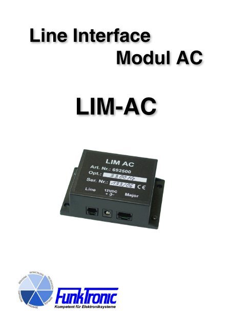
Line Interface<br />
Modul <strong>AC</strong><br />
<strong>LIM</strong>-<strong>AC</strong>
Inhaltsverzeichnis<br />
Seite<br />
Begriffe und Abkürzungen 2<br />
Technische Daten 2<br />
Allgemeine Eigenschaften 3<br />
Anschaltbeispiele Major 4a (5a), <strong>AC</strong>-gekoppelt 3<br />
Steckerbelegung <strong>LIM</strong>-<strong>AC</strong> 4<br />
Blockschaltplan 4<br />
Abgleichanweisung 5<br />
Programmieranweisung 6<br />
Registerbelegung EEPROM <strong>LIM</strong>-<strong>AC</strong> 6<br />
NF-Schwellwerte für die Register 00 und 01 7<br />
Bestellinformationen 7<br />
Allgemeine Sicherheitshinweise 8<br />
Rücknahme von Altgeräten 8<br />
Terms and Shortcuts<br />
<strong>LIM</strong>-<strong>AC</strong> Line Interface Modul <strong>AC</strong><br />
Line 2-Wire Connection<br />
Radio 2-Way Radio Base Station<br />
Z R Reference Termination Impedance,<br />
equivalent to a real 2-Wire Connection according to german TBR 15<br />
Technical Data<br />
Power Supply<br />
Voltage +12 V DC +/- 30%<br />
Current consumption 25 mA<br />
AF-Input Level<br />
Factory default 500 mV<br />
Input impedance 600 Ohm<br />
AF-Output Level<br />
Factory default 500 mV<br />
Adjustment range - 24 dBm to - 5 dBm<br />
Input Level Line<br />
Factory default - 8 dBm ( 500 mV at AF-Output)<br />
Input impedance<br />
Output Level Line<br />
Z<br />
R<br />
Factory default - 6 dBm, AF (500 mV at AF-Input) plus pilot tone<br />
Output impedance Z<br />
R<br />
Weight 77 g<br />
Dimensions (with flange) 100 x 32 x 75 mm<br />
Kompetent für Elektroniksysteme<br />
- 2 -<br />
lim-ac (01.11.2006)
Common Characteristics<br />
The <strong>LIM</strong>-<strong>AC</strong> (Line Interface Modul <strong>AC</strong>) connects a 2 way radio station to its operator device via leased<br />
line. It is certificated according to german TBR 15 and for this can be connected to private and<br />
public/leased lines.<br />
The 2 wire connection is plugged into the connector Line. The operator device is connected to the<br />
plug named Major. The connection <strong>LIM</strong>-<strong>AC</strong> to the Major operator device is established through a one<br />
-to-one cable. Standard network patch cords can be used.<br />
On the opposit side the devices FT634a, FT634aC or FT633<strong>AC</strong> can be used.<br />
All operator devices of the Major series (e.g. Major 4a, 5a, 6) can be directly connected to the <strong>LIM</strong>-<br />
<strong>AC</strong>.<br />
Exception:<br />
The Major BOS 4 and Major BOS 8 feature a busy line instead of the 12V power supply on the 8 pole<br />
plug. In this case the <strong>LIM</strong>-<strong>AC</strong> has to be powered via the separate power supply plug.<br />
Examples Major 4a (5a), <strong>AC</strong> coupled<br />
Kompetent für Elektroniksysteme<br />
<strong>LIM</strong>-<strong>AC</strong> (2 wire)<br />
2<br />
<strong>LIM</strong> <strong>AC</strong> incl.<br />
notch filter<br />
option<br />
<strong>LIM</strong> <strong>AC</strong> incl.<br />
notch filter option<br />
2<br />
- 3 -<br />
FT634aC (with channel switching) or<br />
FT633<strong>AC</strong> (with channel switching) or<br />
FT634a (without channel switchong)<br />
Parallel operation of multiple operator devices --> <strong>LIM</strong> <strong>AC</strong> requires notch filter option for pilot tone<br />
2<br />
FT624<br />
2<br />
FT634aC (with channel switching) or<br />
FT633<strong>AC</strong> (with channel switching) or<br />
FT634a (without channel switchong)<br />
lim-ac (01.11.2006)
Connector Layout <strong>LIM</strong>-<strong>AC</strong><br />
2-wire connection<br />
Pin Layout Line ST2<br />
nc 1<br />
nc 2<br />
a 3<br />
b 4<br />
nc = not connected<br />
Block Diagram<br />
Kompetent für Elektroniksysteme<br />
Power Supply<br />
12 Volt<br />
Tip Plus pole<br />
Ring Ground<br />
- 4 -<br />
Operator Device<br />
Pin Layout Radio circuit ST1,<br />
GND<br />
500 mV <br />
GND<br />
+12 V<br />
PTT, active low<br />
4<br />
5<br />
6<br />
AF-Input<br />
500 mV ==> GND<br />
7<br />
8<br />
lim-ac (01.11.2006)
Adjustment<br />
P1 (AF-TX)<br />
Kompetent für Elektroniksysteme<br />
P2<br />
AF-RX<br />
P1<br />
AF-TX<br />
Jumper<br />
Optional notch filter, plugged in on multiple<br />
operator devices in parallel operation.<br />
- 5 -<br />
ST5/Pin 1<br />
ST3/GND<br />
RS232/TTL<br />
P1 sets the level of the pilot tone. The required AF level has to be set within the operator device.<br />
The factory default of P1 is set to the max. permitted level according to TBR 15.<br />
Pilot tone without AF --> - 10 dBm on line<br />
AF Input 500 mV --> - 8 dBm on line<br />
AF plus pilot tone --> - 6 dBm on line<br />
P2 (AF-RX)<br />
Feed line / 2 wire connection with required level and set AF-Output to 500 mV.<br />
Remark:<br />
In public communication networks it is mandatory to terminate the line with the reference terminating<br />
impedance of Zr while sending or receiving. Because of this the FT624 has to be used to connect<br />
multiple <strong>LIM</strong>-<strong>AC</strong> in parallel. This causes a higher insertion loss.<br />
Please consider the programming capabilities of pilot tone and relais.<br />
TXD<br />
RXD<br />
lim-ac (01.11.2006)
Programming Guide<br />
Connect the plug ST3 of the <strong>LIM</strong>-<strong>AC</strong> to the serial interface of the PC via adapter TTL/RS232 (e.g.<br />
FunkTronic RS232AD1). Start a perminal emulation prgramm (e.g. Hyperterminal, minicom). The<br />
settings are 9600 baud, 8 data bits, no parity, one stopp bit and no flow control protocol.<br />
Hit the ENTER key and you will receive the following display message:<br />
Kompetent für Elektroniksysteme<br />
<strong>LIM</strong>_<strong>AC</strong> (C) FunkTronic 02-03<br />
Software: `<strong>LIM</strong>_<strong>AC</strong>` V1.1 vom 24.09.03<br />
Pilotton: 3300 Hz<br />
Rxx Read EEPROM Register xx<br />
Pxx yy Program yy in EEPROM Register xx<br />
X Reset<br />
If you enter R followed by a two digit register number and a final ENTER the setting of the corresponding<br />
register will be displayed.<br />
Programming a register works the same way but with the P button instead of R.<br />
Enter P followed by the two digit register number followed by the register value and the final ENTER<br />
key.<br />
Input of X resets the unit.<br />
Register description EEPROM <strong>LIM</strong>-<strong>AC</strong><br />
Register Function<br />
00 Vref for Squelch detection leveö (Factory default --> 0x0A = 280 mV)<br />
01 Vref for Squelch turn off level (Factory --> 0x06 = 140 mV)<br />
02 Number of consecutive slopes onf start of Squelch<br />
A break of 3.6 ms without slope resets the counter<br />
Fectory default --> 0x05 = 6 slopes without break longer than 3,6 ms is detected as<br />
Squelch<br />
03 Follow-up time for Squelch detection x 10 ms<br />
Factory default --> 0x50 = 50 x 10 ms = 500 ms<br />
04 Locking time past PTT for Squelch detection x 10 ms<br />
Factory default --> 0x10 = 10 x 10 ms = 100 ms<br />
05 TX-Mode Low-Nibble --> Pilotton bei TX 1 = an, 0 = aus<br />
High-Nibble --> Relais bei TX<br />
0 = TX-Relais on for TX, RX-Relais on for RX<br />
1 = TX-Relais always on, RX-Relais on for RX - default<br />
2 = TX-Relais an bei TX, RX-Relais immer an<br />
3 = TX-Relais immer an, RX-Relais immer an<br />
Factory default --> 0x11 = Relais and pilot tone on for TX<br />
- 6 -<br />
lim-ac (01.11.2006)
AF level for the registers 00 snd 01<br />
Register ca . AF level/mV<br />
Value<br />
00 1,0<br />
01 20<br />
02 45<br />
03 60<br />
04 95<br />
05 125<br />
06 140<br />
07 160<br />
08 185<br />
09 230<br />
0A 280<br />
0B 325<br />
0C 370<br />
0D 415<br />
0E 465<br />
0F no Squelch detection<br />
Ordering Information<br />
Part No. Description<br />
692500 Line Interface Module <strong>AC</strong>, <strong>LIM</strong>-<strong>AC</strong><br />
901200 Option notch filter 3300 Hz<br />
Kompetent für Elektroniksysteme<br />
- 7 -<br />
lim-ac (01.11.2006)
General Safety Instructions<br />
Please read the operating instructions carefully before installation and setup.<br />
The relevant regulations must be complied to when working with 230V line voltage, two-wirelines,<br />
four-wire-lines and ISDN-lines. It is also very important to comply to the regulations<br />
and safety instructions of working with radio installations.<br />
Please comply to the following safety rules:<br />
- All components may only be mounted and maintained when power is off.<br />
- The modules may only be activated if they are built in a housing and are<br />
scoop-proof.<br />
- Devices which are operated with external voltage - especially mains voltage -<br />
may only be opened when they have been disconnected from the voltage source<br />
or mains.<br />
- All connecting cables of the electronic devices must be checked for damage<br />
regularly and must be exchanged if damaged.<br />
- Absolutely comply to the regular inspections required by law<br />
according to VDE 0701 and 0702 for line-operated devices.<br />
- Tools must not be used near or directly at concealed or visible power lines<br />
and conductor paths and also not at and in devices using external voltage –<br />
especially mains voltage - as long as the power supply voltage has not been<br />
turned off and all capacitors have been discharged. Electrolytic capacitors<br />
can be still charged for a long time after turning off.<br />
- When using components, modules, devices or circuits and equipment the<br />
threshold values of voltage, current and power consumption specified in the<br />
technical data must absolutely be complied to. Exceeding these threshold<br />
values (even if only briefly) can lead to significant damage.<br />
- The devices, components or circuits described in this manual are only<br />
adapted for the specified usage. If you are not sure about the purpose of the<br />
product, please ask your specialized dealer.<br />
- The installation and setup have to be carried out by professional personnel.<br />
Factory returning of old equipment<br />
According to German law concerning electronic devices old devices cannot be disposed off<br />
as regular waste. Our devices are classified for commercial use only. According to § 11 of<br />
our general terms of payment and delivery, as of November 2005, the purchasers or users<br />
are obliged to return old equipment produced by us free of cost. FunkTronic GmbH will<br />
dispose of this old equipment at its own expense according to regulations.<br />
Please send old equipment for disposal to: FunkTronic GmbH<br />
Breitwiesenstraße 4<br />
36381 Schlüchtern<br />
>>> Important hint: freight forward deliveries cannot be accepted by us.<br />
February 2 nd , 2006<br />
Kompetent für Elektroniksysteme<br />
Subject to change, Errors excepted<br />
- 8 -<br />
lim-ac (01.11.2006)