Black Box Model: TZTBB - Furuno USA
Black Box Model: TZTBB - Furuno USA
Black Box Model: TZTBB - Furuno USA

Create successful ePaper yourself
Turn your PDF publications into a flip-book with our unique Google optimized e-Paper software.
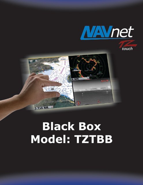
<strong>Black</strong> <strong>Box</strong><br />
<strong>Model</strong>: <strong>TZTBB</strong>
1. <strong>Model</strong>: <strong>TZTBB</strong><br />
2. Overview<br />
2.1 Outlook<br />
2.2 Specifications<br />
Index<br />
3. <strong>TZTBB</strong> Operations – User Interface<br />
3.1 Basic User Interface<br />
3.2 What Can You Do With a Mouse/Trackball with Wheel?<br />
4. About Monitors and <strong>TZTBB</strong> Supporting Resolutions<br />
4.1 Required Specifications of Multi Touch Monitors for <strong>TZTBB</strong><br />
4.2 Introducing Tested Monitors at FEC<br />
4.3 <strong>TZTBB</strong> Supporting Resolutions<br />
5. Installing <strong>TZTBB</strong><br />
5.1 Dimensions<br />
5.2 Compatible Sensors<br />
5.3 Interconnection<br />
5.4 I/O – Cabling at I/O<br />
5.5 Clone Output from Two (2) DVI-D Ports<br />
5.6 HDD Pocket<br />
5.7 USB Ports<br />
6. Software Versions – TZT9/14 and <strong>TZTBB</strong>
1. <strong>Model</strong>: <strong>TZTBB</strong><br />
The NavNet <strong>TZTBB</strong> is the <strong>Black</strong> <strong>Box</strong> (or “BB”) solution for our NavNet TZtouch series. As boat console spaces are getting<br />
wider, sometimes 14” or 15” screens are not big enough to fill the space. The new NavNet <strong>TZTBB</strong> <strong>Black</strong> <strong>Box</strong> MFD provides<br />
the scalability to meet the display requirements of any size vessel demanding larger screens, while maintaining the<br />
high-performance standards set by the TZT9 and TZT14. The <strong>TZTBB</strong> also incorporates the multi touch user-interface, as<br />
well as an increased number of I/O’s.<br />
2. Overview<br />
2-1. Outlook<br />
The <strong>TZTBB</strong> is comprised of two major components: an MPU002 processor unit and a PSD002 switch box. The processor<br />
is based on the TZT14 architecture with increased I/O’s. The switch box incorporates a power key for turning the system<br />
on/off, (2) SDXC slots for loading charts and software, an LED status indicator, and a built-in buzzer for<br />
alarm/acknowledgement sounds. By connecting a multi touch monitor (supplied separately), enhanced multi touch<br />
operation is available on much larger display sizes. Unlike conventional BB models, a dedicated control unit is not<br />
supplied or required for operation, since full control can be achieved through the use of a multi touch monitor. The <strong>TZTBB</strong><br />
MFD utilizes a modified version of the standard TZtouch software with a dedicated UI to achieve full system control.<br />
Note:<br />
Processor Unit MPU002 Switch <strong>Box</strong> PSD002<br />
(1) Multi touch monitors supplied separately. See Section 4 of this guide for product specifications and other details<br />
regarding multi touch monitors.<br />
Increased I/O’s with protection cover, cable clamp<br />
SDXC slots<br />
(2) See Section 3-2 for system control/operation using a mouse or trackball (w/clickable wheel).<br />
LED<br />
Power key<br />
3
2-2. Specifications<br />
(1) Standard Equipment/Components<br />
Comprised of <strong>Model</strong>s Remarks Carton<br />
Processor Unit MPU002 -<br />
Switch <strong>Box</strong> PSD002 -<br />
Includes: 5 m power cable<br />
MJ-A3SPF0017-050ZC<br />
3 m network cable<br />
MOD-WPAS0001-030+<br />
2 m multi cable<br />
FRUDD-18AFFM-L180<br />
10 A, same cable as TZT9/14<br />
Water proof connector, same<br />
cable as MFD8/12 and TZT9/14<br />
Same cable as MFD8/12/BB and<br />
TZT9/14<br />
Installation materials and accessories<br />
(2) Product Specifications & Side-by-Side Comparison<br />
All items are packed in one box.<br />
General <strong>TZTBB</strong> TZT14 TZT9<br />
LCD Size - 14.1-inch wide 9-inch wide<br />
Resolution(s)<br />
Supporting both wide and non-wide:<br />
1280 x 720 (Wide – 16:9)<br />
1280 x 800 (Wide – 16:10)<br />
1280 x 960 (Non-Wide – 4:3)<br />
1280 x 1024 (Non-Wide – 5:4) * (1)<br />
1280×800 (WXGA) 800×480 (WVGA)<br />
Brilliance - 900 cd/㎡<br />
Touch Screen - Available (Multi touch, up to two contact points)<br />
Chart Same as TZT9/14 MapMedia mm3d format (Same charts as NavNet 3D)<br />
Chart Storage Same as TZT9/14 * (2) SDXC Cards (SD, SDHC, or SDXC)<br />
Wireless LAN USB-type Built-in * (3), (4) Built-in<br />
Language Same as TZT9/14<br />
English (<strong>USA</strong>), English (UK), French, Spanish,<br />
Germany, Italian, Portuguese, Swedish, Danish,<br />
Norwegian, Finish, Greek, Chinese, Japanese<br />
Environment Same as TZT9/14 -15℃ to +55℃ (Built-in Wireless LAN: 0℃ to +55℃)<br />
Protection Level<br />
Processor Unit: IP22<br />
Switch <strong>Box</strong>: IP56 (front),<br />
IP22 (rear)<br />
IP56 (IP22 with connector boot)<br />
Power Consumption 38.4 W 60 W 42 W<br />
L (540)<br />
W (430)<br />
H (450)<br />
13.94 kg<br />
4
Note:<br />
(1) See Section 4-3 for detailed descriptions of resolutions.<br />
(2) Optional SD, SDHC, and/or SDXC cards for chart storage (supplied separately).<br />
(3) A USB-type Wireless LAN module (WLAN-USB-01-C) is inserted into one of the USB ports at the factory. See Section<br />
5-3 for details.<br />
(4) The built-in Wireless LAN for the <strong>TZTBB</strong> is approved for use in the US (FCC), Canada (IC), Europe (CE), Australia/New<br />
Zealand, and Japan only. Use an external router (supplied separately) for use in other areas. The Chinese version does<br />
not have Wireless LAN built-in.<br />
I/O <strong>TZTBB</strong> TZT14 TZT9<br />
LAN 3 ports<br />
(100 BASE-TX)<br />
3 ports<br />
(100 BASE-TX)<br />
CAN bus 1 port 1 port<br />
NMEA0183 No port No port<br />
USB 6 ports (USB2.0) * (1) 1 port (USB2.0)<br />
Video Input (Composite) 2 ports (RCA) 2 ports (RCA)<br />
DVI-D Output 2 ports (Clone Mode) * (2) 1 port<br />
1 port<br />
(100 BASE-TX)<br />
Power Output for DRS No port (PSU012/013 required) * (3) No port (PSU012/013 required)<br />
SD Card Slots (Front) 2 slots for SDXC (optional) * (4) 2 slots for SDXC (optional)<br />
Note:<br />
(1) Five (5) USB ports are available on the I/O board and one (1) USB port is inside the <strong>TZTBB</strong> processor unit. The<br />
internal USB port can be used to connect an optional USB-HDD. See Section 5-7 for more information.<br />
(2) Extended mode is not available as a display option. See Section 5-6 for details.<br />
(3) Radar power is supplied via an external power supply. The PSU012 is required for DRS2D/4D/4A/6A/12A and the<br />
PSU013 is required for DRS25A.<br />
(4) SD slots are available on the PSD002 switch box.<br />
Feature(s) <strong>TZTBB</strong> TZT9/14<br />
Points 30,000 points<br />
20 characters for name per point<br />
64 characters for comment per point<br />
Routes 200 routes w/500 points<br />
20 characters for name per point<br />
64 characters for comment per point<br />
Tracks 30,000 points<br />
ARPA 30 targets for display<br />
AIS 100 targets for display<br />
5
(3) Comparison with MFDBB<br />
General <strong>TZTBB</strong> MFDBB<br />
Resolution(s)<br />
Supports wide and non-wide aspects:<br />
1280 x 720 (16:9)<br />
1280 x 800 (16:10)<br />
1280 x 960 (4:3)<br />
1280 x 1024 (5:4)<br />
Supports only non-wide aspect:<br />
800 x 600 (SVGA)<br />
1024 x 768 (XGA)<br />
1280 x 1024 (SXGA)<br />
Touch Screen Capability With optional multi touch monitor -<br />
Chart MapMedia mm3d format MapMedia mm3d format<br />
Chart Storage SDXC Cards (SD, SDHC, or SDXC) Internal HDD<br />
Wireless LAN USB-type Built-in N/A<br />
Language<br />
Environment<br />
Protection Level<br />
English (<strong>USA</strong>), English (UK), French,<br />
Spanish, Germany, Italian, Portuguese,<br />
Swedish, Danish, Norwegian, Finish, Greek,<br />
Chinese, Japanese<br />
-15℃ to +55℃<br />
(Built-in Wireless LAN: 0℃ to +55℃)<br />
Processor Unit: IP22<br />
Switch <strong>Box</strong>: IP56 (front)<br />
IP22 (rear)<br />
English (<strong>USA</strong>), English (UK), French,<br />
Spanish, Germany, Italian, Portuguese,<br />
Swedish, Danish, Norwegian, Finish, Dutch,<br />
Greek, Chinese, Japanese<br />
Processor Unit: 0℃ to +45℃<br />
Control Unit: -15℃ to +55℃<br />
Processor Unit: IP20<br />
Control Unit: IP56 (front)<br />
IP20 (rear)<br />
Consumption 38.4 W 104 W (no DRS connected)<br />
I/O <strong>TZTBB</strong> MFDBB<br />
LAN 3 ports (100 BASE-TX)<br />
- All 3 ports for sensors<br />
4 ports (100 BASE-TX)<br />
- 2 ports for MCU002<br />
- 2 ports for sensors<br />
CAN bus 1 port 1 port<br />
NMEA0183 No port 3 ports<br />
USB 6 ports (USB2.0) 4 ports (USB2.0)<br />
Video Input (Composite) 2 ports (RCA) 4 ports (BNC)<br />
DVI-D Output 2 ports (Clone Mode) 2 ports (Extended Mode)<br />
Power Output for DRS No port (PSU012/013 required) 1 port (Up to DRS12A)<br />
SD Card Slots 2 slots for SDXC (in PSD002 switch box) 2 slots for SD (in MCU001 control unit)<br />
Feature(s) <strong>TZTBB</strong> MFDBB<br />
Points 30,000 points<br />
20 characters for name per point<br />
64 characters for comment per point<br />
2,000 points<br />
13 characters for name per point<br />
64 characters for comment per point<br />
6
Routes 200 routes w/500 points<br />
20 characters for name per point<br />
64 characters for comment per point<br />
200 routes w/100 points<br />
13 characters for name per point<br />
64 characters for comment per point<br />
Tracks 30,000 points 10,000 points<br />
ARPA 30 targets for display 30 targets for display<br />
AIS 100 targets for display 100 targets for display<br />
7
3. <strong>TZTBB</strong> Operations – User Interface<br />
3-1. Basic User Interface<br />
The <strong>TZTBB</strong> supports the same multi touch user interface as the TZT9 & TZT14, but it has been optimized for full-touch<br />
operations with the following unique UI changes:<br />
(1) RotoKey items and contextual menus appear at a tapped spot on the display<br />
(2) Slider bar for making adjustments<br />
(3) Virtual Home key icon added to display<br />
(1) RotoKey Items and Contextual Menus<br />
When connecting to a large monitor, it can be difficult to select RotoKey items or contextual menu items when they are<br />
only shown at the right side of the screen. The <strong>TZTBB</strong> offers the ability to view RotoKey items and contextual menus<br />
at a tapped spot on the display. The following table describes the differences between the <strong>TZTBB</strong> and TZT9/14.<br />
Items <strong>TZTBB</strong> TZT9/14<br />
RotoKey Appears as a blue menu at a tapped<br />
Contextual<br />
Menus<br />
Pop-up<br />
Window<br />
spot on the display<br />
(See examples below)<br />
Appears at a tapped spot with<br />
RotoKey items and contexts<br />
Appears at the right side of the screen in gold<br />
(after pressing the RotoKey)<br />
Appears at the right side of the screen in blue<br />
(after tapping somewhere on the screen)<br />
Appears at a tapped spot<br />
Pop-up window and contextual menus “More…” indication<br />
After tapping on the screen, three selections appear at the tapped spot in a pop-up<br />
window. Tap [More…]. To view the full contents of the RotoKey menu.<br />
After pressing [More…], additional<br />
selections become visible. (*)<br />
8
*Note: To show full items at the tapped spot after pressing<br />
[More…], it is recommended to set the RotoKey items to<br />
be fully shown as shown at right.<br />
[Menu] – [General] – [RotoKeys] – [Full]<br />
With [Base] selected in RotoKey menu, not all the items<br />
will appear even after pressing [More…]. Long press the<br />
context to show all the items.<br />
Here are some additional examples of these contextual menus in other screen modes.<br />
Pop-up window and contextual menus “More…” indication<br />
9
(2) Slider Bar<br />
In addition to Pinch-to-Zoom capability, a slider bar has been implemented for zooming capability.<br />
To show and operate the slider bar:<br />
1. Tap the number in the range box, so the slider bar appears.<br />
2. Grab the ball on the slider and shift it up and down to dynamically zoom the chart in/out.<br />
3. To zoom-in/out in smaller increments, simply tap the bar above or below the ball.<br />
Note:<br />
In the Plotter and Weather screen, the range box consists of number (range scale) and compass icon. Tap the number<br />
to show the slider bar and tap the compass icon to change the orientation between North-Up and Head-Up.<br />
1<br />
3<br />
3<br />
2<br />
Note<br />
10
Here are some additional examples of the slider bar in other screen modes.<br />
Radar Fish Finder<br />
The current range scale appears on the slider bar next to the ball.<br />
2-Split Screen 3-Split Screen<br />
The slider bar appears at the right side of each split screen window.<br />
11
(3) Virtual Home Key Icon<br />
A virtual home key icon has been added to the top-right of the screen, as shown in the following screenshots. Tap the<br />
icon to go to the Home page.<br />
Plotter Screen Menu Page<br />
3-2. What Can You Do With a Mouse/Trackball with Wheel?<br />
The NavNet <strong>TZTBB</strong> includes a pre-installed HID driver for connecting a generic HID-mouse (USB-mouse), or a trackball<br />
with a wheel. You can use this feature to operate the <strong>TZTBB</strong> from a remote place on the boat, or for installations with<br />
non-touch monitors. The below table outlines how each of these components work with the <strong>TZTBB</strong>:<br />
1<br />
2<br />
Sample: LTSX50<br />
(from NSI, Belgium)<br />
Components Functions<br />
4<br />
3<br />
1. Wheel<br />
Acts as the RotoKey of TZT9/14:<br />
(1) Rotate to zoom in/out.<br />
(2) Push to show RotoKey items in gold at the right side<br />
of the screen as shown at right.<br />
(3) Select RotoKey items or contextual menus<br />
2. Left-click Single tap, drag/scroll with trackball<br />
3. Right-click<br />
Acts as Function Gesture:<br />
Right-click to activate preset functions in [Menu] – [General] – [Function<br />
Gesture].<br />
4. Trackball Select a spot to be tapped, drag/scroll with left-click<br />
12
Limitations and Notes<br />
The NavNet <strong>TZTBB</strong> software is optimized for the multi touch user interface. Although most operations are available with<br />
a mouse/trackball and wheel, there are some limitations that should be taken into consideration:<br />
1. Limitation in 3D Mode – Pan/Tilt<br />
You can switch the display to 3D mode by selecting [3D Mode]<br />
from the context menu. However, you will not be able to<br />
pan/tilt the chart using a mouse. Sliding the screen with<br />
two fingers is the only way to pan/tilt it. The chart will be<br />
displayed at the default angle when in 3D mode, as shown at<br />
the right. If you have previously panned/tilted the chart with<br />
two fingers, the screen will remain in the previously-set<br />
angle/view. This is the only function that is inaccessible when<br />
using a mouse/trackball.<br />
2. Note on Active Window<br />
When in split screen mode, placing the cursor on a different screen will not activate the window. To activate a window,<br />
left-click on the screen or mode that you wish to activate.<br />
3. Note on “+” Cursor<br />
The “+” cursor is displayed at the tapped spot on the screen in the Plotter, Radar,<br />
Fish Finder and Weather page modes. Placing or moving the cursor does not<br />
show the “+” cursor. Left-click on the mouse to show pop-up windows in place of<br />
tapping the screen.<br />
4. Note on Menu – Second Layer<br />
The first layer of the Menu can be scrolled using the RotoKey or mouse wheel,<br />
while the RotoKey is not used for the second layer. Left-click and drag the<br />
mouse to scroll the second layer of the Menu, as you would with a single finger,<br />
or click the arrow keys at the top or bottom of the layer.<br />
5. Note on Cursor Operation and Touch Operation<br />
While a cursor is in motion, touch operations are unavailable. When you switch to touch operation, discontinue use of the<br />
mouse/trackball cursor operation.<br />
“+” Cursor<br />
2 nd Layer<br />
1 st Layer<br />
13
4. About Monitors and <strong>TZTBB</strong> Supporting Resolutions<br />
4-1. Required Specifications of Multi Touch Monitors for <strong>TZTBB</strong><br />
When selecting an optional multi touch monitor for use with the <strong>TZTBB</strong>, the specifications below should be noted:<br />
1. Must be compatible with DVI-D input<br />
* Like the TZT9 & TZT14, the <strong>TZTBB</strong> outputs images via DVI-D.<br />
2. “Capacitive” type multi touch monitors are recommended rather than “Optical” type.<br />
* Capacitive touch monitors offer a better sense of multi touch control compared to optical touch monitors. Capacitive<br />
monitors give you full control of the <strong>TZTBB</strong> at your fingertips!<br />
3. USB interface for multi touch<br />
* Multi touch commands are communicated via USB between the <strong>TZTBB</strong> and a monitor, like the TZT9 and TZT14.<br />
* Windows 7 compatible monitors are equipped with a USB interface for multi touch.<br />
4. No dedicated driver installation required for multi touch function<br />
* The TZT9, TZT14 and <strong>TZTBB</strong> will not accept an external driver to be installed. A dedicated driver cannot be installed<br />
on the TZT9/14/BB.<br />
* When selecting a multi touch monitor, be sure the multi touch interface is available without installing a<br />
dedicated driver.<br />
* Some monitors may require the installation of dedicated drivers for the multi touch interface. If you connect such a<br />
monitor to the <strong>TZTBB</strong>, images will appear; however, multi touch capabilities will not function properly.<br />
4-2. Introducing Tested Monitors at FEC<br />
Several brands and models of multi touch monitors have been thoroughly tested throughout the <strong>TZTBB</strong> development<br />
process. Some of these displays are introduced with screenshots below.<br />
Hatteland Display<br />
Series-X: HD 17T21 (17”), HD 19T21 (19”), and HD 24T21 (24” Wide)<br />
In the following example, three <strong>TZTBB</strong> processors are connected to 17”, 19” and 24” wide monitors. The <strong>TZTBB</strong> images<br />
are properly scaled on both wide and non-wide aspect ratios.<br />
http://www.hatteland-display.com/index.php<br />
14
HD 17T21 (17”) HD 19T21 (19”) HD 24T21 (24” Wide)<br />
Olorin (Sweden)<br />
VL221D (22” Wide)<br />
The “VL221D” consists of several part numbers according to<br />
specifications. The monitor shown at right is the “VL22176SPCAP,” with a<br />
sunlight readable AR film (550 cd).<br />
http://www.olorin.com/images/userfiles/products/431.pdf<br />
The Sharp “PN-L702B” is not designed for marine use, but<br />
has been used at boat shows to demonstrate the <strong>TZTBB</strong> for<br />
visitors. This monitor uses “optical” touch technology.<br />
http://www.sharp-world.com/products/professional-monit<br />
ors/products/pn-l802b_l702b_l602b/index.html<br />
Sharp<br />
PN-L702B (70” Wide)<br />
Yokohama International Boat Show 2012<br />
15
4-3. <strong>TZTBB</strong> Supporting Resolutions<br />
Boot Dusseldorf 2013 Miami International Boat Show 2013<br />
The <strong>TZTBB</strong> has the following native resolutions built-in, supporting both wide and non-wide aspect ratios.<br />
No Pixels Aspect Ratio<br />
(1) 1280 x 720 Wide – 16:9<br />
(2) 1280 x 800 Wide – 16:10<br />
(3) 1280 x 960 Non-Wide – 4:3<br />
(4) 1280 x 1024 Non-Wide – 5:4<br />
The horizontal resolution is fixed to 1280 pixels, while the vertical resolution adjusts to accommodate multiple different<br />
aspect ratios. The following illustration compares all the native resolutions for the <strong>TZTBB</strong>.<br />
Comparison – Native Resolutions<br />
(1) 1280 x 720 (Wide, 16:9)<br />
(2) 1280 x 800 (Wide, 16:10)<br />
(3) 1280 x 960 (Non-Wide, 4:3)<br />
(4) 1280 x 1024 (Non-Wide, 5:4)<br />
The <strong>TZTBB</strong> automatically selects one of the resolutions above and outputs images to the monitor by scaling according to<br />
the monitor’s resolution. Example: if the <strong>TZTBB</strong> is connected to a monitor with a resolution of 1920 x 1080 (16:9), the<br />
<strong>TZTBB</strong> automatically selects and displays 1280 x 720 pixels on the screen by scaling the native resolution.<br />
16
The following screenshots represent a comparison of wide and non-wide screen resolutions. Different aspect ratios,<br />
screen sizes and resolutions provide slightly different screen layouts.<br />
Native Wide Resolution<br />
1280 x 720 (16:9)<br />
Native Non-Wide Resolution<br />
1280 x 1024 (5:4)<br />
Displayed on 24” wide monitor (1920 x 1080) by scaling Displayed on 19” monitor (1280 x 1024)<br />
17
Tips: Non-Wide Images with NavNet Remote App<br />
When non-wide monitors are connected to the <strong>TZTBB</strong>, both edges of the NavNet Remote app will appear blank on the<br />
iOS device due to the iOS device having a different aspect ratio than the <strong>TZTBB</strong>. The following screenshots demonstrate<br />
various iPad screen layouts when connected to a <strong>TZTBB</strong> with both wide and non-wide monitors.<br />
<strong>TZTBB</strong> w/19” Non-Wide Monitor iPad – <strong>TZTBB</strong> w/Non-Wide iPad – <strong>TZTBB</strong> w/Wide<br />
19” non-wide<br />
iPad<br />
<strong>TZTBB</strong> connected to a 19” non-wide<br />
monitor (aspect ratio 5:4). <strong>TZTBB</strong><br />
screen images are shown on both iPad<br />
and iPhone<br />
iPhone<br />
The <strong>TZTBB</strong> images fit on the iPad<br />
screen. However, the NavNet Remote<br />
app’s icons overlap the screen image.<br />
When the <strong>TZTBB</strong> is connected to a<br />
wide-screen monitor, the NavNet<br />
Remote app appears as shown above.<br />
(iPad and iPhone are trademarks of Apple Inc.)<br />
18
5. Installing <strong>TZTBB</strong><br />
5-1. Dimensions<br />
(1) Processor Unit MPU002<br />
19
Note: The <strong>TZTBB</strong> is supplied with a pair of mounting knobs and two cosmetic “cover-up” stickers. The knobs can be<br />
attached to both sides of the processor unit, either for mounting or for holding and transporting the <strong>TZTBB</strong> processor<br />
unit. When the knobs are not necessary, the two “cover-up” stickers can be placed over the holes, as shown below.<br />
Knobs<br />
Stickers<br />
Cosmetic stickers placed over mounting knob<br />
holes on both sides of the processor<br />
Knobs attached to both sides of the processor:<br />
easier to hold and carry the processor unit<br />
20
5-2. Compatible Sensors<br />
(2) Switch <strong>Box</strong> PSD002<br />
The <strong>TZTBB</strong> is compatible with all of the same sensors (DFF Fish Finders, DRS Radars, GP330B, etc.) used for NavNet 3D<br />
and the TZT9/14.<br />
21
5-3. Interconnection<br />
(1) Single Station<br />
The following diagram represents a single station <strong>TZTBB</strong> installation: One processor with one monitor.<br />
DVI-IN<br />
L<br />
A<br />
N<br />
Ethernet<br />
Hub<br />
DVI-OUT “0”<br />
Station 1<br />
DVI‐D<br />
Ethernet<br />
Sensors<br />
Monitor<br />
(Local Supply)<br />
Processor Unit<br />
MPU‐002<br />
USB<br />
WLAN‐USB‐01‐C<br />
12‐24<br />
VDC<br />
DVI-D Port 1: Primary<br />
DVI-D Port 2: Secondary<br />
Switch <strong>Box</strong><br />
PSD‐002<br />
DVI-D<br />
USB<br />
Ethernet<br />
CAN bus (NMEA2000)<br />
Others<br />
CAN bus<br />
(NMEA2000)<br />
Sensors<br />
Note: The <strong>TZTBB</strong> includes four (4) DVI-D ports. The<br />
DVI-D ports on the bottom I/O board function as a DVI<br />
splitter. The DVI-D images are output from DVI-OUT “0”<br />
and provided to the DVI-IN. These images are split into<br />
both DVI-D Port 1 and Port 2. See the following<br />
examples for dual station configurations.<br />
22
(2) Dual Station – One Processor (Clone Mode)<br />
The following diagram represents a dual station <strong>TZTBB</strong> installation: One processor unit (MPU002) and switch box<br />
(PSD002) with two monitors. In this configuration, the monitors are in “clone” mode. Images displayed on Station 2 will<br />
be identical to those displayed on Station 1. Extended mode is not available on the <strong>TZTBB</strong>. For additional details on clone<br />
mode, please see Section 5-6.<br />
L<br />
A<br />
N<br />
Ethernet<br />
Hub<br />
DVI‐D<br />
Monitor<br />
(Local Supply)<br />
Processor Unit<br />
MPU‐002<br />
USB<br />
12‐24<br />
VDC<br />
Switch <strong>Box</strong><br />
PSD‐002<br />
Station 2<br />
Station 1 Station<br />
(Clone)<br />
2<br />
Ethernet<br />
Sensors<br />
WLAN‐USB‐01‐C<br />
CAN bus<br />
(NMEA2000)<br />
Sensors<br />
DVI-D<br />
USB<br />
Ethernet<br />
CAN bus (NMEA2000)<br />
Others<br />
Monitor<br />
(Local Supply)<br />
23
(3) Dual Station – Two Processors<br />
The following diagram represents a dual station <strong>TZTBB</strong> installation: Two processor units (MPU002) and switch boxes<br />
(PSD002) with two monitors. In this configuration, both monitors are independent of each other, allowing full system<br />
control on each display, simultaneously.<br />
L<br />
A<br />
N<br />
Ethernet<br />
Hub<br />
Processor Unit<br />
MPU‐002<br />
Switch <strong>Box</strong><br />
PSD‐002<br />
Station 1 Station 2<br />
DVI‐D<br />
Ethernet<br />
Sensors<br />
Monitor<br />
(Local Supply)<br />
USB<br />
WLAN‐USB‐01‐C<br />
12‐24<br />
VDC<br />
Monitor<br />
(Local Supply)<br />
CAN bus<br />
(NMEA2000)<br />
Sensors<br />
DVI-D<br />
USB<br />
Ethernet<br />
CAN bus (NMEA2000)<br />
Others<br />
12‐24<br />
VDC<br />
24
(4) Multiple Stations – <strong>TZTBB</strong> and TZT9/14<br />
The <strong>TZTBB</strong> can be networked via Ethernet and CAN bus (NMEA2000) in a multi-station network with the TZT9 and TZT14<br />
as shown in the following diagram.<br />
L<br />
A<br />
N<br />
Ethernet<br />
Hub<br />
Switch <strong>Box</strong> PSD002:<br />
Monitor<br />
(Local Supply)<br />
Processor Unit<br />
MPU‐002<br />
12‐24<br />
VDC<br />
Switch <strong>Box</strong><br />
PSD‐002<br />
Station 1 Station 2<br />
DVI‐D<br />
Ethernet<br />
Sensors<br />
USB<br />
WLAN‐USB‐01‐C<br />
Station 3<br />
TZT9/14<br />
(5) Notes<br />
Monitor<br />
(Local Supply)<br />
CAN bus<br />
(NMEA2000)<br />
Sensors<br />
DVI-D<br />
USB<br />
Ethernet<br />
CAN bus (NMEA2000)<br />
Others<br />
The PSD002 is supplied with a 5 meter cable attached to the rear panel and protected with rubber and metal plate. The<br />
5 meter cable pair consists of a USB cable for the SDXC card reader and a power cable for the on/off switch. These cables<br />
can be split at the processor end for installation purposes.<br />
12‐24<br />
VDC<br />
25
Processor Unit MPU002:<br />
PSD002 Switch box<br />
Front side<br />
5 meter cable pair<br />
(<strong>Furuno</strong> pen shown<br />
to compare cable<br />
thickness)<br />
(1) A USB-type Wireless LAN module (WLAN-USB-01-C) is inserted<br />
into one of the USB ports at the factory as shown at right. Note that<br />
the Chinese version of the <strong>TZTBB</strong> does not include a pre-installed<br />
Wireless LAN.<br />
(2) A WARNING sticker on the protection cover for the bottom I/O<br />
board outlines the correct interconnection procedures. Remember to<br />
use DVI-D cables, not RGB, when installing a <strong>TZTBB</strong>.<br />
Rear side:<br />
5 meter cable<br />
attached and<br />
protected with<br />
rubber and metal<br />
plate<br />
Wires split for<br />
connection to the<br />
<strong>TZTBB</strong> processor<br />
000-177-340<br />
WLAN-USB-01-C<br />
26
5-4. I/O – Cabling at I/O<br />
The photos below demonstrate the proper I/O cabling procedures for single station <strong>TZTBB</strong> installations.<br />
Standard DVI cable<br />
From DVI-OUT “0” to DVI-IN<br />
Protection Cover<br />
for Top I/O (*)<br />
(1) Before Cabling<br />
Protection Cover<br />
for Bottom I/O (*)<br />
Switch <strong>Box</strong> PSD002<br />
PWR line and USB line<br />
* Note: Protection covers consist of a case, sponge, metal plate, and cable clamp.<br />
WLAN-USB-01-C<br />
USB cable from a<br />
multi touch monitor<br />
DVI cable from<br />
multi touch monitor<br />
Protection Cover – Top I/O Protection Cover – Bottom I/O<br />
27
(2) After Cabling<br />
5-5. Clone Output from Two (2) DVI-D Ports<br />
All connectors and WLAN-USB-01-C are<br />
inserted into each port and protected with<br />
covers. The cables are secured into place with<br />
cable ties.<br />
Note: the two (2) DVI-D output ports support “clone” mode only: In this mode, both monitors display the same image.<br />
DVI-IN<br />
DVI-OUT “0”<br />
Cables fixed at the<br />
cable clamps<br />
WLAN-USB-01-C<br />
inside the cover<br />
DVI-D Port 1: Primary<br />
DVI-D Port 2: Secondary<br />
DVI-D Output Port 1:<br />
For Primary Monitor – Station 1 (e.g. at main bridge)<br />
DVI-D Output Port 2:<br />
For Secondary Monitor – Station 2 (e.g. at fly bridge)<br />
The aspect ratio and resolution of the monitor connected to Port 1 will also be applied to Port 2. To show images properly<br />
on both monitors, be sure the aspect ratios and resolutions of the two monitors match. The following examples<br />
demonstrate acceptable and unacceptable resolutions.<br />
28
(1) Acceptable – Two monitors (same screen size) with same resolutions and aspect ratios<br />
In this example, the same 24” wide Hatteland monitors (Series-X HD 24T21) are connected to the <strong>TZTBB</strong>. Both monitors<br />
properly scale and display the <strong>TZTBB</strong> images.<br />
(2) Acceptable – Two monitors (different screen size) with same resolutions and aspect ratios<br />
In this example, a Hatteland 17” monitor (HD 17T21) and 19” monitor (HD 19T21) are connected to the <strong>TZTBB</strong>. These<br />
monitors support the same resolution and aspect ratio, although screen sizes are different. Both monitors properly scale<br />
and display Plotter and Radar images in clone mode.<br />
(3) Unacceptable – Two monitors with different resolutions and aspect ratios<br />
When two monitors with different resolutions and/or aspect ratios are connected to the <strong>TZTBB</strong>, the secondary monitor<br />
(connected to DVI-D Port 2) will not be shown properly. In this example, a Hatteland 19” (HD 19T21, aspect ratio 5:4)<br />
and 24” wide (HD 24T21, aspect ratio 16:9) are connected to the <strong>TZTBB</strong>. The monitor connected to DVI-D Port 2 does<br />
not scale properly (Radar rings appear oval). This is because the resolution and aspect ratio of the primary monitor is<br />
also applied to the secondary monitor.<br />
Port 1 (Primary)<br />
Non-Wide<br />
Port 2 (Secondary)<br />
Wide<br />
Port 2 (Secondary)<br />
Non-Wide<br />
Port 1 (Primary)<br />
Wide<br />
29
5-6. HDD Pocket<br />
The TZT9/14/BB can read charts directly from a USB hard drive. For convenience, the<br />
<strong>TZTBB</strong> processor unit (MPU002) has a space accessible from the rear panel for<br />
connecting and storing an option HDD with all of the chart files. The following photos<br />
show a generic USB HDD (shown at right) installed inside the MPU002.<br />
Note: The HDD size should be 90 x 134 x 20 mm (W x H x D) to fit in the case.<br />
MPU002 rear side HDD installed inside MPU002<br />
The pocket is covered by a metal plate, which is attached<br />
to the processor with screws.<br />
The USB-HDD can be installed with the USB cable connected to<br />
the internal USB port.<br />
* Note: It is more convenient to use a USB-HDD with the cable running straight from the top side of the HDD than one<br />
with the cable running sideways.<br />
USB cable running straight from the top (preferred) USB able running sideways<br />
30
5-7. USB Ports<br />
There are six (6) USB ports: five (5) ports on the I/O board and one (1) port inside the case for connecting an optional<br />
USB Chart HDD. These USB ports can be used as follows:<br />
1 PSD002 (USB line) 4 Wireless LAN (USB type, inserted at factory)<br />
2 Multi touch monitor (USB line) 5 Mouse or trackball device with wheel<br />
3 Multi touch monitor (USB line), for clone 6 USB-HDD, connected to the internal USB port<br />
6. Software Versions – TZT9/14 and <strong>TZTBB</strong><br />
The <strong>TZTBB</strong> is shipped with software v2.02 from the factory. There is no difference in functionality from the TZT9/14;<br />
however, the graphics driver for the <strong>TZTBB</strong> has been updated to v2.02 to be compatible with dual monitor installations.<br />
Future software revisions will be in common with all TZtouch models (TZT9, TZT14, <strong>TZTBB</strong>).<br />
<strong>Model</strong>s Versions Future Version<br />
TZT9 and TZT14 v2.01<br />
<strong>TZTBB</strong> v2.02<br />
Common versions<br />
31