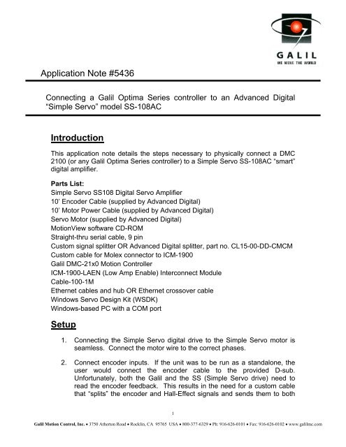
Application Note #5436 Introduction Setup - Galil
Application Note #5436 Introduction Setup - Galil
Application Note #5436 Introduction Setup - Galil

You also want an ePaper? Increase the reach of your titles
YUMPU automatically turns print PDFs into web optimized ePapers that Google loves.
<strong>Application</strong> <strong>Note</strong> <strong>#5436</strong><br />
Connecting a <strong>Galil</strong> Optima Series controller to an Advanced Digital<br />
“Simple Servo” model SS-108AC<br />
<strong>Introduction</strong><br />
This application note details the steps necessary to physically connect a DMC<br />
2100 (or any <strong>Galil</strong> Optima Series controller) to a Simple Servo SS-108AC “smart”<br />
digital amplifier.<br />
Parts List:<br />
Simple Servo SS108 Digital Servo Amplifier<br />
10’ Encoder Cable (supplied by Advanced Digital)<br />
10’ Motor Power Cable (supplied by Advanced Digital)<br />
Servo Motor (supplied by Advanced Digital)<br />
MotionView software CD-ROM<br />
Straight-thru serial cable, 9 pin<br />
Custom signal splitter OR Advanced Digital splitter, part no. CL15-00-DD-CMCM<br />
Custom cable for Molex connector to ICM-1900<br />
<strong>Galil</strong> DMC-21x0 Motion Controller<br />
ICM-1900-LAEN (Low Amp Enable) Interconnect Module<br />
Cable-100-1M<br />
Ethernet cables and hub OR Ethernet crossover cable<br />
Windows Servo Design Kit (WSDK)<br />
Windows-based PC with a COM port<br />
<strong>Setup</strong><br />
1. Connecting the Simple Servo digital drive to the Simple Servo motor is<br />
seamless. Connect the motor wire to the correct phases.<br />
2. Connect encoder inputs. If the unit was to be run as a standalone, the<br />
user would connect the encoder cable to the provided D-sub.<br />
Unfortunately, both the <strong>Galil</strong> and the SS (Simple Servo drive) need to<br />
read the encoder feedback. This results in the need for a custom cable<br />
that “splits” the encoder and Hall-Effect signals and sends them to both<br />
1<br />
<strong>Galil</strong> Motion Control, Inc. • 3750 Atherton Road • Rocklin, CA 95765 USA • 800-377-6329 • Ph: 916-626-0101 • Fax: 916-626-0102 • www.galilmc.com
devices. Figure (1) shows a picture of the cable that was built at <strong>Galil</strong>.<br />
Figure (2) shows the wire pinouts.<br />
Figure (1)- Picture of Signal Splitter<br />
Figure (2)- Signal Splitter Schematic<br />
Advanced Digital can now provide a manufactured signal splitter. This is a<br />
cleaner solution than the handmade version shown above.<br />
2<br />
<strong>Galil</strong> Motion Control, Inc. • 3750 Atherton Road • Rocklin, CA 95765 USA • 800-377-6329 • Ph: 916-626-0101 • Fax: 916-626-0102 • www.galilmc.com
Figure (3)- Manufactured Signal Splitter<br />
3. Connect Enable/Motor Command cable from ICM 1900 to SS drive. This<br />
requires a cable with a 16-pin Molex connector on one end and flying<br />
leads on the other. Figure (3) shows the Enable/Motor Command cable<br />
attached to the ICM-1900.<br />
3<br />
<strong>Galil</strong> Motion Control, Inc. • 3750 Atherton Road • Rocklin, CA 95765 USA • 800-377-6329 • Ph: 916-626-0101 • Fax: 916-626-0102 • www.galilmc.com
Figure (4)- Enable/Motor Command Connector Cable<br />
4. Connect the SS drive to the PC using the serial cable.<br />
5. Install the MotionView software as per the instructions.<br />
6. Install WSDK if not already done.<br />
7. Connect to the DMC-2100 via Ethernet if not already done.<br />
8. Make the appropriate connections from the ICM-1900 to the SS drive.<br />
Figure (4) shows a general schematic. Figure (5) shows a photo of the<br />
entire system. <strong>Note</strong> that only the bare minimum connections are shown.<br />
Specific systems may require shielding, external sensors, or shared logic<br />
circuits.<br />
4<br />
<strong>Galil</strong> Motion Control, Inc. • 3750 Atherton Road • Rocklin, CA 95765 USA • 800-377-6329 • Ph: 916-626-0101 • Fax: 916-626-0102 • www.galilmc.com
DS2<br />
DS1<br />
DS1<br />
SS108<br />
CONNECTIONS<br />
N/C1<br />
TX2<br />
RX3<br />
NC4<br />
NC5<br />
NC6<br />
NC7<br />
NC8<br />
RES<br />
ENC A+1<br />
ENC A-2<br />
ENC B+3<br />
ENC B-4<br />
ENC Z+5<br />
ENC Z-6<br />
ENC COM 7<br />
ENC SHLD 8<br />
ENC PWR (+5) 9<br />
HALL A- 10<br />
HALL A+ 11<br />
HALL B+ 12<br />
HALL C+ 13<br />
HALL B- 14<br />
HALL C- 15<br />
TB2 +10 VDC 1<br />
ANALOG COM 2<br />
-10VDC 3<br />
AN REF IN+ 4<br />
AN REF IN- 5<br />
SHIELD 6<br />
AN OUT-1 7<br />
AN OUT-2 8<br />
ENABLE IN 9<br />
+5VDC OUT 10<br />
LOGIC COM 11<br />
SPARE 12<br />
SPARE 13<br />
SPARE 14<br />
SPARE 15<br />
FAULT OUTPUT 16<br />
DIAGNOSTIC<br />
LED<br />
EARTH GROUND SCREW<br />
TB1<br />
MOTOR OUTPUT PHASE U<br />
MOTOR OUTPUT PHASE V<br />
MOTOR OUTPUT PHASE W<br />
5<br />
110V AC IN<br />
TO<br />
CONTROLLER<br />
THREE PHASE BRUSHLESS MOTOR<br />
Figure (5)- ICM Wiring Schematic<br />
TO COM PORT FOR MOTIONVIEW<br />
ICM 1900/ICM 2900<br />
GND<br />
RP1 U6<br />
<strong>Galil</strong> Motion Control, Inc. • 3750 Atherton Road • Rocklin, CA 95765 USA • 800-377-6329 • Ph: 916-626-0101 • Fax: 916-626-0102 • www.galilmc.com<br />
7406<br />
MOCMD<br />
AMPEN<br />
GND<br />
GND<br />
+MAX<br />
-MAX<br />
+MBX<br />
-MBX<br />
+INX<br />
-INX<br />
LAEN CHIP (7406)
Figure (6)- System Layout<br />
9. Connect to the controller using WSDK.<br />
10. Set appropriate error conditions, such as Off-On-Error, Error Limit,<br />
Torque Limits, and low values for PID. Turn the motor off using MO.<br />
11. Power up the SS-108.<br />
12. Check for proper encoder feedback in both directions by rotating the<br />
motor shaft back and forth while issuing ‘TP’.<br />
13. With the motor off, the Simple Servo diagnostic LED should be blinking<br />
green.<br />
14. Connect to the SS using MotionView. You need to go on-line and<br />
connect using COM1. <strong>Note</strong> that using a Simple Servo motor, the amp<br />
will automatically configure parameters.<br />
15. Return to WSDK. Issue a SH. The diagnostic LED on the SS-108<br />
should turn solid green. If it does not, or a red LED state occurs, ensure<br />
the proper Hall-Effect transitions, check for overspeed conditions, and<br />
confirm proper motor phasing.<br />
6<br />
<strong>Galil</strong> Motion Control, Inc. • 3750 Atherton Road • Rocklin, CA 95765 USA • 800-377-6329 • Ph: 916-626-0101 • Fax: 916-626-0102 • www.galilmc.com
16. Check the motor shaft for servo. WARNING: Axis is live and can run<br />
away if not properly tuned. Use caution.<br />
17. If the axis maintains position, tune the axis in either Torque or Velocity<br />
mode.<br />
Tuning<br />
Torque Mode<br />
Torque mode is used when the system motion can be best described as point-topoint.<br />
The critical aspects of the motion are fastest settling time, minimum<br />
overshoot, and/or accurate profiling. Te enable torque mode, choose Torque<br />
mode in the MotionView software. Choose an appropriate amplifier gain, and<br />
tune the axis using WSDK.<br />
Several general tests were performed in torque mode. The following data<br />
represents results from using a SS-108 amplifier with a Simple Servo 100 Watt<br />
brushless servo, part number 524-20-516. Any other system will result in<br />
significantly different gains and bandwidths.<br />
No Load Current<br />
Test procedure: Tune the PID, FA, FV, and OF to within system tolerance.<br />
Issue JG commands to a constant velocity, and measure the average torque.<br />
Data:<br />
Speed (RPM) JG (cts/sec) TT (avg)<br />
60 8,000 0.15<br />
600 80,000 0.2<br />
1200 160,000 0.27<br />
3000 400,000 0.25<br />
4500 600,000 0.5<br />
-60 -8,000 -0.15<br />
-600 -80,000 -0.12<br />
-1200 -160,000 -0.25<br />
-3000 -400,000 -0.45<br />
-4500 -600,000 -0.3<br />
Analysis: The System required equivalent torque in the positive and negative<br />
direction. The amplifier exhibited no undesirable increases in no-load current<br />
throughout the speed range.<br />
7<br />
<strong>Galil</strong> Motion Control, Inc. • 3750 Atherton Road • Rocklin, CA 95765 USA • 800-377-6329 • Ph: 916-626-0101 • Fax: 916-626-0102 • www.galilmc.com
Smooth Motion<br />
Test procedure: Vary the PID and the Jog speed and query the min/max error<br />
Data:<br />
Speed (Cts/Sec) KP KD Min Error Max Error<br />
60,000 10 100 10 22<br />
60,000 10 150 10 19<br />
60,000 10 200 8 21<br />
60,000 20 200 1 15<br />
60,000 33 150 0 9<br />
60,000 5 80 24 35<br />
160,000 5 80 37 43<br />
-160,000 5 80 -35 -40<br />
400,000 5 80 50 62<br />
200,000 5 80 37 42<br />
300,000 5 80 47 51<br />
350,000 5 80 49 55<br />
450,000 5 80 50 53<br />
600,000 5 80 57 60<br />
-600,000 5 80 -45 -49<br />
Analysis: The first five data points show the effect of increasing KP and KD on<br />
the error range. Once adequately tuned, the remaining data points show a stable<br />
error range, neither increasing nor decreasing dramatically throughout the speed<br />
range.<br />
System frequency response<br />
Test procedure: Run the ‘System Response on Closed Loop’ test in WSDK.<br />
Vary the PID values and determine system bandwidth and maximum system<br />
gain.<br />
Data:<br />
KP KD KI Bandwidth (Hz) Max Gain<br />
5 80 0 90 1.3<br />
5 150 0 120 1.44<br />
12 150 0 100 1.5<br />
Analysis: A no-load system frequency response running in torque mode results<br />
in a bandwidth of up to 120 Hertz with a maximum gain of 1.44. A loaded system<br />
will produce drastically different results.<br />
8<br />
<strong>Galil</strong> Motion Control, Inc. • 3750 Atherton Road • Rocklin, CA 95765 USA • 800-377-6329 • Ph: 916-626-0101 • Fax: 916-626-0102 • www.galilmc.com
Point-to-point settling time<br />
Test procedure: Run the Point-to-Point tuning test in WSDK, and determine best<br />
settling time.<br />
Data:<br />
KP KD KI Settling time, Samples<br />
5 50 0 18<br />
5 50 1 13<br />
5 100 2 11<br />
15 50 0 13<br />
15 50 1 10<br />
15 100 2 10<br />
25 50 0 18<br />
25 50 1 12<br />
25 100 2 8<br />
Analysis: With TM (time constant) set to the default 1000 µsec, KP 25, KD 100,<br />
KI 2 resulted in a minimum settling time of 8 milliseconds.<br />
Velocity Mode<br />
Velocity mode is most often used if the system is typically commanded to slew at<br />
a constant RPM. In this mode, the user must choose Velocity Mode from the<br />
MotionView software. Nominal P gain and I gain must be set. <strong>Note</strong> that gains<br />
are cumulative. Any proportional gains on the controller are multiplied by the<br />
amplifier gains. For the tests performed here, the P gain was set to 400 and the I<br />
gain was set to 0.<br />
No load current<br />
Test Procedure: Set KP=19, KD=0, and KI=0. Jog at various speeds and record<br />
the average torque.<br />
Data:<br />
JG (cts/sec) TT<br />
-100,000 -1.56<br />
-60,000 -1.22<br />
-30,000 -0.78<br />
-10,000 -0.34<br />
-1,000 -0.06<br />
1,000 0.10<br />
10,000 0.35<br />
30,000 0.81<br />
60,000 1.30<br />
100,000 1.60<br />
9<br />
<strong>Galil</strong> Motion Control, Inc. • 3750 Atherton Road • Rocklin, CA 95765 USA • 800-377-6329 • Ph: 916-626-0101 • Fax: 916-626-0102 • www.galilmc.com
Analysis: Applied torque is essentially linear throughout the specified velocity<br />
range.<br />
Motion smoothness<br />
Test procedure: Jog at 100,000 counts/sec and vary the amplifier P gain, and<br />
controller KP and KD. View the error range.<br />
Data:<br />
P Gain KP KD Min Error Max Error Error Range<br />
20 6 64 217 226 9<br />
100 6 25 202 209 7<br />
400 6 0 174 180 6<br />
400 8 0 174 180 7<br />
Analysis: By relying on the P Gain and minimizing the <strong>Galil</strong> velocity loop gain<br />
(KD), the range of error was reduced. <strong>Note</strong> that for constant jog moves, FV<br />
provides an open-loop voltage bias to eliminate the error caused by the back-<br />
EMF of the motor. To determine the necessary FV, jog the axis at the desired<br />
speed, and increment FV until the error range is within system specifications.<br />
Tuning<br />
Test procedure: Tune the axis using General Tuning, Point-to-Point, and Curve<br />
Follower methods in WSDK.<br />
Data:<br />
Tuning Method P Gain I Gain KP KD KI FV FA<br />
Point-Point 400 0 4 0 0.12 0 0<br />
Curve Follow 400 0 9 10 0.25 0 0<br />
General 400 0 5 10 0 0 25<br />
Analysis: A combination of high P Gain, no I Gain, and moderately low PID<br />
values coupled with modest FV and FA values, led to fast, reliable, stable system<br />
behavior. <strong>Note</strong> that any system will have any combination of values. These<br />
values are for reference only.<br />
10<br />
<strong>Galil</strong> Motion Control, Inc. • 3750 Atherton Road • Rocklin, CA 95765 USA • 800-377-6329 • Ph: 916-626-0101 • Fax: 916-626-0102 • www.galilmc.com
Conclusion<br />
The Simple Servo model SS-108 is an effective, mid-cost solution to numerous<br />
motion applications. Several strengths and weaknesses are listed below.<br />
Strengths<br />
¥ If the consumer is interfacing to a Simple Servo motor, the setup and<br />
configuration is instant. The Amplifier communicates with the motor and<br />
draws it’s parameters from a database. This database contains several<br />
other makes and models of brushless motors.<br />
¥ The MotionView software is easy to learn and navigate. Error conditions<br />
are stored in an easily accessed location.<br />
¥ Connections and pin-outs are fully labeled on the drive.<br />
¥ Customer support was courteous and well-informed.<br />
Weaknesses<br />
¥ The drive requires the user to either enter a model number held in a<br />
database or fully specify the motor/encoder/Hall Effect parameters. If<br />
these properties are not known, the drive will not function. A motor selftest<br />
would be most helpful.<br />
¥ As per the manufacturer specifications, the encoder feedback rate is<br />
limited to 3.0 MHz. <strong>Galil</strong> Optima Series controllers can handle up to 12.0<br />
MHz encoder feedback, so the consumer must choose encoder<br />
resolutions wisely.<br />
¥ The troubleshooting section of the manual is extremely limited.<br />
<strong>Setup</strong> and tuning is of average complexity. The amplifier gains appear linear<br />
throughout. The packaging and connections are well done with the exceptions<br />
mentioned above. Support from Advanced Digital was very good. In conclusion,<br />
the Simple Servo SS-108 coupled with a Simple Servo motor can provide reliable<br />
motion in both torque and velocity mode.<br />
11<br />
<strong>Galil</strong> Motion Control, Inc. • 3750 Atherton Road • Rocklin, CA 95765 USA • 800-377-6329 • Ph: 916-626-0101 • Fax: 916-626-0102 • www.galilmc.com