Braced and Shear Wall Requirements int he IRC Building Code
Braced and Shear Wall Requirements int he IRC Building Code
Braced and Shear Wall Requirements int he IRC Building Code
Create successful ePaper yourself
Turn your PDF publications into a flip-book with our unique Google optimized e-Paper software.
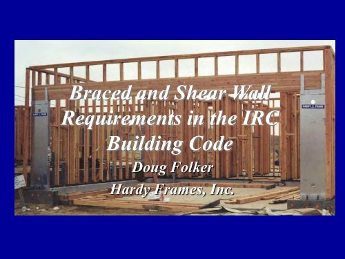
<strong>Braced</strong> <strong>and</strong> <strong>S<strong>he</strong>ar</strong> <strong>Wall</strong><br />
<strong>Requirements</strong> in t<strong>he</strong> <strong>IRC</strong><br />
<strong>Building</strong> <strong>Code</strong><br />
Doug Folker<br />
Hardy Frames, Inc.
Copyright Materials<br />
This presentation is protected by US <strong>and</strong><br />
International Copyright laws. Reproduction,<br />
distribution, display <strong>and</strong> use of t<strong>he</strong> presentation<br />
without written permission of t<strong>he</strong> speaker is<br />
prohibited.<br />
Hardy Frame ®
Learning Objectives<br />
•At t<strong>he</strong> end of this program, participants will have learned:<br />
1. All loads (e.g., vertical loads, lateral loads, impact loads, etc.) on a building or<br />
structure must be provided with a continuous path to t<strong>he</strong> foundation, connections must<br />
also be designed to resist <strong>and</strong> transfer t<strong>he</strong> applied loads to t<strong>he</strong> foundation. T<strong>he</strong><br />
connections must be adequately designed to transfer all of t<strong>he</strong> loads.<br />
2. <strong>Braced</strong> walls are constructed by using prescribed methods <strong>and</strong> techniques called out<br />
in t<strong>he</strong> building codes, SDC C & greater. W<strong>he</strong>n wind speeds fall outside t<strong>he</strong> scope of<br />
prescriptive codes, engineered s<strong>he</strong>ar walls must be used.<br />
3. Collector elements serve to transfer forces between floor diaphragms <strong>and</strong> members<br />
of t<strong>he</strong> lateral force resisting system. Connections of adequate size, type, capacity <strong>and</strong><br />
spacing are required to ensure t<strong>he</strong> continuous load path from t<strong>he</strong> horizontal lateral loadresisting<br />
member or system to t<strong>he</strong> vertical lateral load-resisting member or system.<br />
4. T<strong>he</strong> reaction at t<strong>he</strong> base of a structure due to an applied lateral load, or sliding force,<br />
is t<strong>he</strong> most common structural failure noted after seismic activity. Adequate fastening <strong>and</strong><br />
connection detailing is critical to avoid compromising t<strong>he</strong> s<strong>he</strong>ar wall elements. Horizontal<br />
sliding may be resisted by t<strong>he</strong> use of connectors at connection po<strong>int</strong>s.
• Background<br />
Agenda<br />
• <strong>Code</strong> Review <strong>and</strong> Explanation<br />
– SDC A, B, <strong>and</strong> C Wind < 110<br />
– <strong>Braced</strong> <strong>Wall</strong> Lines<br />
– <strong>Braced</strong> <strong>Wall</strong> Panels<br />
– Narrow Options<br />
• Designing for t<strong>he</strong> <strong>Code</strong><br />
– Design Strategies<br />
– Creating <strong>Wall</strong> Bracing Plans
What Could Have Prevented This?
What Causes <strong>S<strong>he</strong>ar</strong> in a Structure?<br />
•High Winds (Hurricanes/Tornados Gusts)<br />
•In t<strong>he</strong> United States – t<strong>he</strong> minimum wind design speed is 90<br />
mph; equivalent to about 25 psf of lateral loads<br />
•Seismic<br />
•Seismic maps for 2006 IBC increased many SDC in t<strong>he</strong><br />
Sout<strong>he</strong>ast.
Seismic Map Eastern US<br />
Seismic Map SDC C = of 33 %g Eastern US<br />
•1952 Earthquake<br />
•Measuring 5.5<br />
•2011 Earthquake<br />
•Measuring 5.6<br />
•2008 Earthquake<br />
•Measuring 5.2<br />
SDC D1 = 50 %g<br />
SDC D2 = 83 %g<br />
•1980 Earthquake<br />
•Measuring 7.2<br />
•1897 Earthquake<br />
•Measuring 5.9<br />
•1944 Earthquake<br />
•Measuring 5.8<br />
•2011<br />
•Earthquake<br />
•Measuring 5.8<br />
•1886<br />
Earthquake<br />
•Measuring 7.3
Basic Wind Speed Map<br />
Eastern US<br />
(based on 3-second gusts in mph)<br />
Min. 90 mph
Result of <strong>S<strong>he</strong>ar</strong><br />
• Structural Failure<br />
• Cracked Veneer (Brick or Stucco)<br />
• Cracked Windows or Window<br />
Frames<br />
• Damaged Drywall<br />
ALL THESE ITEMS COST $$ AND LOST<br />
PRODUCTIVITY
<strong>Building</strong> <strong>Code</strong><br />
MMC presentation in DC<br />
• Multihazard Mitigation Council (MMC)<br />
– Public/Private partnership designed to<br />
reduce t<strong>he</strong> societal <strong>and</strong> economic costs of<br />
natural hazards<br />
• Costs:<br />
– FEMA grants for flood, wind <strong>and</strong> earthquake<br />
mitigation totaled $3.5 Billion between 1993<br />
<strong>and</strong> 2003<br />
– Per analysis; each $1 spent for mitigation<br />
saved $4 for reconstruction.<br />
– Similarly, t<strong>he</strong> <strong>Building</strong> <strong>Code</strong> is <strong>int</strong>ended to<br />
minimize/eliminate reconstruction costs <strong>and</strong><br />
ot<strong>he</strong>r related costs of catastrop<strong>he</strong>s.
Wind Load Path
Lateral Loads Basics<br />
Components of load<br />
Sliding<br />
Overturning<br />
Racking
Lateral Loads Basics<br />
Resistance to Sliding <strong>and</strong> Overturning
Construction Trends<br />
•Smaller footpr<strong>int</strong>s<br />
•Larger openings<br />
•More multi-story structures<br />
•Mechanical fasteners<br />
Result:<br />
•Less wall area to transfer<br />
lateral loads in a structure!!
What is New ?<br />
• Old building codes: SBC<br />
– 1999 SBC had 2 pages +/-<br />
– Required engineered connections<br />
– Min. width of braced wall panel is 4’-0<br />
– No narrow options<br />
• New building codes: IBC & <strong>IRC</strong><br />
– More <strong>int</strong>ricate requirements<br />
– <strong>IRC</strong> 2006 - 7 pages<br />
– Narrow options<br />
– <strong>IRC</strong> 2012 – 32 pages
<strong>Braced</strong> <strong>Wall</strong>s in t<strong>he</strong> 2012 <strong>IRC</strong><br />
Continuous improvement to t<strong>he</strong> organization of BW requirements<br />
Reorganized to consolidate BWL length, spacing <strong>and</strong> orientation <strong>int</strong>o<br />
one section<br />
BWP now allowed to be up to 10ft from end of BWL instead of 12.5ft<br />
Wind adjustment footnotes have now been consolidated <strong>int</strong>o a table<br />
Bracing methods consolidated <strong>int</strong>o one section<br />
Minimum BWP lengths consolidated <strong>int</strong>o one table<br />
All ABW now consolidated <strong>int</strong>o one section<br />
Simplified BW section added for low wind <strong>and</strong> low seismic areas.
Today’s Discussion<br />
• 2006 International Residential <strong>Code</strong><br />
Section R602.10`<br />
• 2007 Supplement <strong>IRC</strong> Section R602.10<br />
• A Guide to 2006 Wood <strong>Wall</strong> Bracing<br />
Provisions<br />
• Limiting discussion to SDC A, B, <strong>and</strong> C
<strong>IRC</strong> Chapter 3<br />
Design Limitations<br />
• Wind < 100 mph to < 110 mph in hurricane-prone<br />
regions<br />
• Seismic – SDC A,B,C, D 1,D 2,D 3<br />
• Snow < 70 psf ground snow load<br />
• 1- <strong>and</strong> 2- family dwellings<br />
• Maximum 3 Stories<br />
• Height of laterally unsupported (perpendicular) load-<br />
bearing stud is 12’-0”<br />
• Seismic provisions – weight of materials, irregular<br />
buildings<br />
• See Chapter 3 for ot<strong>he</strong>r design limitations
Identify <strong>Braced</strong> <strong>Wall</strong> Lines<br />
SDC A, B, <strong>and</strong> C<br />
General Rule of Thumb:<br />
• All exterior walls should be braced.<br />
• If exterior walls are spaced more than 35’ apart,<br />
some <strong>int</strong>erior walls should also be braced.<br />
– Select t<strong>he</strong> <strong>int</strong>erior walls that have fewer openings<br />
– Select <strong>int</strong>erior walls that begin <strong>and</strong> end at a <strong>Braced</strong><br />
<strong>Wall</strong> Line (implied)
Spacing of <strong>Braced</strong> <strong>Wall</strong> Lines, Cont.<br />
SDC A, B, <strong>and</strong> C<br />
Exception:<br />
• Allowable increases in t<strong>he</strong> spacing of braced wall<br />
lines up to 50’ provided:<br />
– Length to width ratio of t<strong>he</strong> supporting diaphragm<br />
does not exceed 3:1<br />
– Minimum required wall bracing is increased by a<br />
ratio of actual distance between braced wall lines<br />
divided by 35’<br />
– Example: SDC A, wind speed
<strong>Braced</strong> <strong>Wall</strong> Lines<br />
SDC A, B, <strong>and</strong> C<br />
• <strong>Braced</strong> wall panels must line up within a braced<br />
wall line. Out-of-plane offsets of up to 4’ are permitted<br />
provided t<strong>he</strong> total out-of-plane offset does not exceed<br />
8’ within any braced wall line.<br />
Clarified in 2007 Supplement
T<strong>he</strong> total offset from<br />
outside to outside may<br />
be up to 8’<br />
<strong>Braced</strong> <strong>Wall</strong> Lines<br />
SDC A, B, <strong>and</strong> C<br />
Individual offsets<br />
may be up to 4’<br />
Imaginary Line?<br />
This side<br />
exceeds<br />
t<strong>he</strong> 4’ limit.
Create a Grid
<strong>Braced</strong> <strong>Wall</strong> Lines<br />
• <strong>Braced</strong> wall lines shall consist of braced wall<br />
panels<br />
– Panels are required at t<strong>he</strong> corner or within<br />
12’-6” from t<strong>he</strong> corner <strong>and</strong> at least every 25’ on<br />
center<br />
– Refer to 2006 Table R602.10.1 or 2007 Table<br />
R602.10.1(2) for minimum amounts
<strong>Braced</strong> <strong>Wall</strong> Panel Location<br />
• <strong>Braced</strong> wall panels shall begin no more than 12.5’<br />
from each end of a braced wall line, <strong>and</strong> repeat<br />
every 25’ on center.<br />
25’ on center Maximum Less than 12’-6”
What are <strong>Braced</strong> <strong>Wall</strong> Panels?<br />
• T<strong>he</strong> construction of BWP’s must be in accordance with<br />
one of t<strong>he</strong> following methods:<br />
1) LIB - 1x4 continuous (let in) diagonal bracing<br />
• Must be continuous<br />
• Angle of 45 degrees to 60 degrees from top plate to<br />
bottom plate<br />
2) DWB - 5/8” Diagonal Wood Boards applied diagonally<br />
on studs 24” oc<br />
3) WSP - 5/16” min. Wood Structural Panel S<strong>he</strong>athing on<br />
studs 16” oc or 3/8” min S<strong>he</strong>athing on studs 24” oc<br />
(Continuously S<strong>he</strong>at<strong>he</strong>d Method)<br />
4) SFB - Structural Fiberboard S<strong>he</strong>athing on studs 16” oc<br />
5) GB - Gypsum Board on studs 24” oc<br />
6) PBS - Particleboard <strong>Wall</strong> S<strong>he</strong>athing<br />
7) PCP - Portl<strong>and</strong> Cement Plaster on studs 16” oc<br />
8) HPS - Hardboard Panel Siding
Length of <strong>Braced</strong> <strong>Wall</strong> Panels<br />
• For Method 1, t<strong>he</strong> length of t<strong>he</strong> wall is governed by t<strong>he</strong><br />
angle of 45-60 degrees <strong>and</strong> t<strong>he</strong> wall <strong>he</strong>ight.<br />
• For Methods 2, 3, 4, 6, 7 <strong>and</strong> 8 – Each BWP must be at<br />
least 48” oc covering three stud spaces w<strong>he</strong>n studs<br />
are 16” oc <strong>and</strong> 2 stud spaces w<strong>he</strong>n studs are 24” oc<br />
• For Method #5 (Gypsum Board), BWP shall be 96”<br />
w<strong>he</strong>n on one face <strong>and</strong> 48” w<strong>he</strong>n on both faces
<strong>Braced</strong> <strong>Wall</strong> Panel Construction Methods<br />
Minimum Width is 4’-0
Additional Construction Information<br />
S<strong>he</strong>at<strong>he</strong>d–Type Panels<br />
• Each has a specific nail pattern <strong>and</strong> material<br />
thickness<br />
– Compare with common practice<br />
• All require ½” Gypsum board on opposite side (2007)<br />
• In SDC A, B, <strong>and</strong> C some panels over 3’ in length<br />
may count with a reduced effective length (2007)
Panel Jo<strong>int</strong>s<br />
S<strong>he</strong>at<strong>he</strong>d–Type Panels<br />
• All Vertical Jo<strong>int</strong>s of panel s<strong>he</strong>athing shall occur<br />
over <strong>and</strong> be fastened to a stud.<br />
• Horizontal Jo<strong>int</strong>s must occur over <strong>and</strong> be<br />
fastened to 2x blocking<br />
– 2006 Exception: SDC A <strong>and</strong> B <strong>and</strong> detac<strong>he</strong>d<br />
dwellings in SDC C do not require blocking at<br />
horizontal jo<strong>int</strong>s if Method 3 (wood structural panel<br />
s<strong>he</strong>athing) is used.<br />
– 2007 Exception: Blocking is required at all<br />
horizontal jo<strong>int</strong>s in segments that are counted as<br />
braced wall panels unless percentages are at least<br />
twice what is required for t<strong>he</strong> wall (includes wood<br />
structural panel s<strong>he</strong>athing).
<strong>Braced</strong> <strong>Wall</strong> Panel Support<br />
• Joists perpendicular to braced wall panels above<br />
or below must be blocked for connection to wall<br />
plates.<br />
• Joists parallel to braced wall panels, rim joists<br />
also must provide a connection to wall plates.<br />
• <strong>Braced</strong> wall line sills must be anchored to t<strong>he</strong><br />
foundation per R403.1.6.<br />
• Elevated post or pier foundations must be<br />
engineered.
<strong>Braced</strong> <strong>Wall</strong> Panel Construction Methods
Minimum Bracing Amounts<br />
• If stud <strong>he</strong>ight is taller than 10’ <strong>and</strong> less than 12’-0”,<br />
increase quantities by a factor of 1.2<br />
• If wall lines are more than 35’ <strong>and</strong> less than 50’ apart<br />
(parallel), increase quantities by a factor of actual<br />
distance (ft) to furt<strong>he</strong>st (parallel) braced wall line<br />
divided by 35.
T<strong>he</strong>se are minimums
Example<br />
SDC C<br />
First of two story<br />
L1 = 40’<br />
L,M,N = 4’ Each<br />
Total Available Bracing<br />
12’-0”<br />
40 x 30% = 12’<br />
Method 3<br />
40 x 45% = 18’<br />
All Ot<strong>he</strong>r Methods<br />
Lateral Bracing System
Who has 4’-0”?<br />
• T<strong>he</strong> <strong>IRC</strong> offers three options that allow for<br />
narrower than 4’-0 Bracing<br />
– Alternate <strong>Braced</strong> <strong>Wall</strong> Panel (R602.10.6.1)<br />
– Alternate <strong>Braced</strong> <strong>Wall</strong> Panel Adjacent to a<br />
Door or Window Opening (R602.10.6.2)<br />
– Continuous Wood Structural S<strong>he</strong>athing<br />
(R602.10.5)<br />
– Approved Prefabricated Products
<strong>IRC</strong> R602.10.6<br />
Alternate BWP Construction Method<br />
• This section allows a reduction from t<strong>he</strong> 48”<br />
BWP width described in R602.10.4<br />
• Alternate <strong>Braced</strong> <strong>Wall</strong> Panels are permitted to<br />
replace each 4’ requirement, so an Alternate<br />
<strong>Braced</strong> <strong>Wall</strong> Panel should be counted as 4’ w<strong>he</strong>n<br />
calculating t<strong>he</strong> BWP percentage that is required<br />
by Table R602.10.1<br />
• On Foundation – No Upper Story Option
Alternate BWP Construction Method<br />
• Single Story<br />
– Full <strong>he</strong>ight stud to full <strong>he</strong>ight stud<br />
– 3/8” Wood Structural Panel<br />
S<strong>he</strong>athing<br />
– Anchor bolts<br />
– Tie-down with min. 1800 lb capacity<br />
– On foundation<br />
• First Floor of Two Story<br />
– Same as above, except…<br />
– More anchor bolts<br />
– Tie-down capacity min. 3000 lb<br />
– S<strong>he</strong>athing on both sides
Alternate BWP Construction Method<br />
Adjacent to window or door opening<br />
• For use adjacent to a window or door opening with a full length <strong>he</strong>ader.<br />
Each panel has 1 - full <strong>he</strong>ight stud <strong>and</strong> 3 - cripple studs<br />
3 – bottom plates, <strong>and</strong> 1 – top plate beneath t<strong>he</strong> <strong>he</strong>ader
Alternate BWP Construction Method<br />
Adjacent to window or door opening<br />
• For use adjacent to a window or door<br />
opening with a full length <strong>he</strong>ader.<br />
• Requires double 2x12 <strong>he</strong>ader with spacer<br />
on side opposite s<strong>he</strong>at<strong>he</strong>d face<br />
• Header to extend from full length stud to<br />
full length stud.<br />
• Requires 4200 lb tie-down at each end of<br />
each panel (4 – tie downs)<br />
• Requires 1000 straps opposite s<strong>he</strong>at<strong>he</strong>d<br />
face<br />
• Cannot be furt<strong>he</strong>r reduced
Is this what t<strong>he</strong>y had in mind?
Continuous Wood Structural Panel S<strong>he</strong>athing<br />
Definition:<br />
• Wood Structural Panel S<strong>he</strong>athing is provided in<br />
accordance with Method #3 on all s<strong>he</strong>athable areas<br />
of all exterior braced walls, <strong>and</strong> <strong>int</strong>erior wall lines,<br />
w<strong>he</strong>re required.<br />
• 2007 Supplement allows isolated walls to be<br />
continuously s<strong>he</strong>at<strong>he</strong>d provided t<strong>he</strong>re is a 2’-0<br />
panel on both sides of corners<br />
• 2007 Supplement also adds an option for replacing<br />
t<strong>he</strong> 2’-0 panel with an 800 lb tie-down device
Continuous Wood Structural Panel S<strong>he</strong>athing
Corner Construction<br />
Continuous Wood Structural Panel S<strong>he</strong>athing
Continuous Wood Structural Panel S<strong>he</strong>athing<br />
Minimum Lengths<br />
• Bracing panel lengths shall be in accordance<br />
with Table R602.10.5<br />
8’-0”<br />
6’-9”<br />
5’-2”<br />
Opening Heights<br />
9’-0”<br />
7’-7”<br />
5’-10”<br />
10’-0”<br />
8’-6”<br />
6’-6”
<strong>IRC</strong> Table R602.10.5<br />
Continuous Wood Structural Panel S<strong>he</strong>athing<br />
R602.10.5 Applies only to continuously s<strong>he</strong>at<strong>he</strong>d (method 3) construction.<br />
Remember that t<strong>he</strong> bracing percentages in Table R602.10.1 still apply.
Ot<strong>he</strong>r Approved Solutions<br />
• Substituting prefabricated<br />
panels within t<strong>he</strong><br />
requirements of t<strong>he</strong> <strong>IRC</strong><br />
(Prescriptive method of<br />
design)<br />
• Method of design<br />
dependent on requirement<br />
of local codes <strong>and</strong>/or<br />
requirement of builder
Narrow Pre-Fab <strong>S<strong>he</strong>ar</strong> <strong>Wall</strong> Solution<br />
• As Narrow as 9”<br />
• Improves Quality<br />
• Shortens Installation Time<br />
• Reduces Job Call Backs<br />
• Builds a Stronger Safer<br />
Structure<br />
• Get it right t<strong>he</strong> first time!
Is t<strong>he</strong>re enough<br />
room for t<strong>he</strong><br />
panel <strong>and</strong> t<strong>he</strong><br />
cripple studs<br />
supporting t<strong>he</strong><br />
<strong>he</strong>ader?
If you don’t have<br />
room, run t<strong>he</strong><br />
<strong>he</strong>ader above<br />
t<strong>he</strong> panel.
W<strong>he</strong>n Should Builders Engineer<br />
T<strong>he</strong>ir <strong>S<strong>he</strong>ar</strong> <strong>Wall</strong>s?<br />
• Do your homes “fit” <strong>int</strong>o t<strong>he</strong><br />
parameters of t<strong>he</strong> <strong>IRC</strong>?<br />
• Are you comfortable with t<strong>he</strong><br />
“cookbook” method of t<strong>he</strong> <strong>IRC</strong>?<br />
• Do you want t<strong>he</strong> added liability?<br />
• If not, use an engineer.
Design of Structural Elements<br />
• W<strong>he</strong>re a building, or portion of, does<br />
not comply with one or more of t<strong>he</strong><br />
bracing requirements on this section,<br />
those portions shall be designed <strong>and</strong><br />
constructed in accordance with<br />
accepted engineering practice.
Typical<br />
Engineered Design<br />
• Load In – Load Out Designs<br />
• Calculate lateral loads on building<br />
• Transfer loads through diaphragms to walls<br />
– Rigid or Flexible<br />
• Distribute lateral loads through a collector<br />
• Resist loads with s<strong>he</strong>arwalls
WFCM Typical<br />
Design<br />
• Provides tables of wind <strong>and</strong> seismic loads on a wall<br />
line<br />
• Provides calculation methods to make adjustments<br />
to those loads based on environment or building<br />
design<br />
• Offers two methods to determine s<strong>he</strong>ar capacities for<br />
s<strong>he</strong>arwall materials: segmented or perforated<br />
• Provides tables listing materials, construction<br />
parameters, <strong>and</strong> s<strong>he</strong>ar resistance loads per linear<br />
foot for each material type.<br />
Minimum lengths of s<strong>he</strong>arwall section<br />
is governed by aspect ratio
<strong>Wall</strong> Aspect Ratio<br />
<strong>Braced</strong> wall line <strong>and</strong> <strong>Braced</strong> wall panels within t<strong>he</strong> line<br />
Aspect ratio is a proportion of t<strong>he</strong> <strong>he</strong>ight<br />
of a wall to t<strong>he</strong> width of a wall panel.<br />
Length requirement of s<strong>he</strong>arwall sections are based on t<strong>he</strong><br />
Aspect ratios. T<strong>he</strong> hig<strong>he</strong>r t<strong>he</strong> lateral load, t<strong>he</strong> lower t<strong>he</strong><br />
aspect ratio that is allowed.
Max. <strong>S<strong>he</strong>ar</strong> <strong>Wall</strong> Aspect Ratio<br />
IBC Table 2305.3.3<br />
WFCM Table 3.17D<br />
In Structural Design Categories A B, & C t<strong>he</strong> minimum Aspect<br />
Ratio is 3 1/2:1 for wood structural panels<br />
For all ot<strong>he</strong>r materials <strong>and</strong> in Structural Design Categories D & E<br />
t<strong>he</strong> minimum Aspect Ratio is 2:1<br />
Ex.: 3 ½:1 2:1<br />
<strong>Wall</strong> Ht. Min. Width Min. Width<br />
(A to C) (D & E)<br />
8’ 2’-3 1/2” 4’-0”<br />
9’ 2’-7” 4’-6”<br />
10’ 2’-10 1/2” 5’-0”<br />
20’ 5’-9” 10’-0<br />
WALLS NARROWER THAN THE MIN. WIDTH<br />
COUNT AS NOTHING
Prefabricated <strong>S<strong>he</strong>ar</strong> <strong>Wall</strong>s offer an<br />
Engineered Solution<br />
• Hig<strong>he</strong>r strength per linear<br />
foot<br />
• Aspect ratios do not apply<br />
• May eliminate t<strong>he</strong> need for<br />
structural steel<br />
• Proven solution
Design Safety <strong>int</strong>o Narrow Balloon <strong>Wall</strong>s<br />
Narrow Prefabricated<br />
<strong>S<strong>he</strong>ar</strong> Panels<br />
for<br />
Balloon <strong>Wall</strong> Applications
Multi-story applications
Panels on a Beam
• Know t<strong>he</strong> capabilities of t<strong>he</strong> trades<br />
• Underst<strong>and</strong> your builders priorities<br />
• Work with your builder to create a flow chart for<br />
preferred bracing methods based on those<br />
capabilities – include drawings <strong>and</strong> minimum<br />
widths<br />
• Use t<strong>he</strong> 4’-0 offset rule to your advantage<br />
• Utilize <strong>int</strong>erior walls<br />
Applying t<strong>he</strong> <strong>Code</strong><br />
DESIGN<br />
• Move great rooms away from exterior walls or<br />
add covered patios to “laterally support” studs
Applying t<strong>he</strong> <strong>Code</strong><br />
<strong>IRC</strong>602.10<br />
Know t<strong>he</strong> Capabilities of t<strong>he</strong> Trades<br />
Method 1 - Over-Cut Studs
Applying t<strong>he</strong> <strong>Code</strong><br />
Know t<strong>he</strong> Capabilities of t<strong>he</strong>Trades<br />
Methods 3-7<br />
•What fasteners are being used?<br />
•What about t<strong>he</strong> nail pattern?<br />
•Is blocking installed at all jo<strong>int</strong>s?<br />
•What ot<strong>he</strong>r materials will change?<br />
Continuously S<strong>he</strong>at<strong>he</strong>d<br />
•How consistent are your workers?<br />
•What about t<strong>he</strong> corners?<br />
•Interior walls?
Applying t<strong>he</strong> <strong>Code</strong><br />
Know t<strong>he</strong> Capabilities of your Trades<br />
Alternate <strong>Braced</strong> <strong>Wall</strong> Panel<br />
• Tie-Downs<br />
– Will t<strong>he</strong>y be installed at t<strong>he</strong> correct location?<br />
– Is t<strong>he</strong>re a retro-fit?<br />
• Nail Pattern<br />
– Critical<br />
• Extended Header – APA Method<br />
• Plywood on both sides – ABWP First Floor<br />
of Two Story
Applying t<strong>he</strong> <strong>Code</strong><br />
<strong>IRC</strong>602.10<br />
Use t<strong>he</strong> 4’-0 Offset Rule to Your Advantage<br />
Less than 12’-6”<br />
BWP BWP<br />
A Well Planned Upper Floor
Applying t<strong>he</strong> <strong>Code</strong><br />
<strong>IRC</strong>602.10<br />
Utilize Interior <strong>Wall</strong>s<br />
Less than<br />
12’-6<br />
BWP<br />
Collector<br />
?<br />
BWP
Applying t<strong>he</strong> <strong>Code</strong><br />
<strong>IRC</strong>602.10<br />
Move Great Rooms Away From Exterior <strong>Wall</strong>s<br />
Covered Patio?<br />
Are t<strong>he</strong>re any “laterally unsupported studs over 12’-0?<br />
100% <strong>Braced</strong> Opening <strong>Wall</strong>s
Bracing Plans<br />
•Assume SDC B<br />
•Not continuously s<strong>he</strong>at<strong>he</strong>d<br />
•Prefer to use T<strong>he</strong>rmo-Ply on<br />
exterior <strong>and</strong> double-sided<br />
drywall on <strong>int</strong>erior walls<br />
•Base on 4’ sections<br />
•16% upper story<br />
•25% bottom story<br />
•Begin with t<strong>he</strong> Upper Floor<br />
•Identify <strong>Braced</strong> <strong>Wall</strong> Lines<br />
•Begin with t<strong>he</strong> Exterior<br />
•Interior?<br />
•Confirm Plate Heights<br />
•Determine Qty of BWP’s<br />
•Locate <strong>Braced</strong> <strong>Wall</strong> Panels<br />
BWP BWP<br />
BWP BWP<br />
BWP<br />
8’-0 Ceiling<br />
BWP<br />
BWP<br />
BWP<br />
BWP
Bracing Plans<br />
•Identify <strong>Braced</strong> <strong>Wall</strong> Lines<br />
•Exterior<br />
•Interior<br />
•Confirm Plate Height<br />
•Determine Qty of BWP’s<br />
•Distance Between <strong>Wall</strong>s<br />
•Locate BWP’s<br />
9’-0 Ceiling
Bracing Plan<br />
BWP<br />
Feel better by adding anot<strong>he</strong>r BWP?<br />
•Calculation: Methods 2-8, 20’ x 25% = 5’-0”<br />
•Calculation: Method 3, 20’ x 16% = 3’-3”
?<br />
Bracing Plan<br />
More than 12’-6”<br />
BWP<br />
Options: •Calculation: Methods 2-8, 30’ x 25% x 38’/35’ = 8’-2”<br />
•Alternate <strong>Braced</strong> <strong>Wall</strong> Panel (s<strong>he</strong>at<strong>he</strong>d both sides)<br />
•42” •Calculation: BWP with Method an effective 3, 30’ length x 16% of x 30” 38’/35’ (New = 2007) 5’-3”<br />
•Move t<strong>he</strong> window or door to allow for a 48” Panel<br />
•12” Prefabricated Panel (Add anot<strong>he</strong>r window?)
Bracing Plan<br />
BWP<br />
30’-0<br />
More than 12’-6”<br />
•Calculation: •Extend Methods t<strong>he</strong> <strong>he</strong>ader 2-8, 30’ <strong>and</strong> x use 25% a 9” x 38’/35’ or 12” = 8’-2”<br />
Prefabricated <strong>S<strong>he</strong>ar</strong> Panel<br />
•Calculation: Method 3, 30’ x 16% x 38’/35’ = 5’-3”
Prefabricated <strong>S<strong>he</strong>ar</strong> <strong>Wall</strong>s<br />
T<strong>he</strong> Best Solution<br />
For<br />
Narrow Applications
Thank You
•THERE IS NO COMPARISON!<br />
•T<strong>he</strong> Original Steel <strong>S<strong>he</strong>ar</strong> <strong>Wall</strong><br />
System


